LED Lighting in Automotive Applications - 아이씨뱅큐 Power Constraints in Automotive 3...
27
LED Lighting in Automotive Applications
Transcript of LED Lighting in Automotive Applications - 아이씨뱅큐 Power Constraints in Automotive 3...

LED Lighting in Automotive ApplicationsApplications
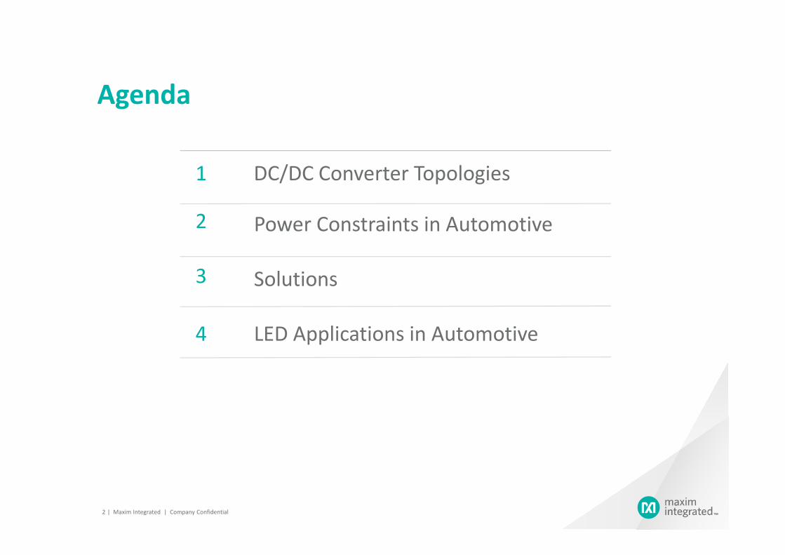
Agenda
1
Power Constraints in Automotive2
Solutions3
DC/DC Converter Topologies
Solutions3
4 LED Applications in Automotive
| Maxim Integrated | Company Confidential 2
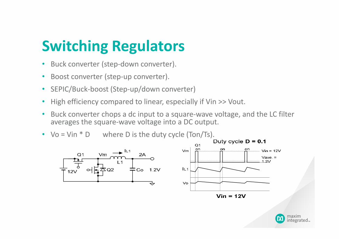
Switching Regulators• Buck converter (step-down converter).
• Boost converter (step-up converter).
• SEPIC/Buck-boost (Step-up/down converter)
• High efficiency compared to linear, especially if Vin >> Vout.
• Buck converter chops a dc input to a square-wave voltage, and the LC filter averages the square-wave voltage into a DC output.averages the square-wave voltage into a DC output.
• Vo = Vin * D where D is the duty cycle (Ton/Ts).
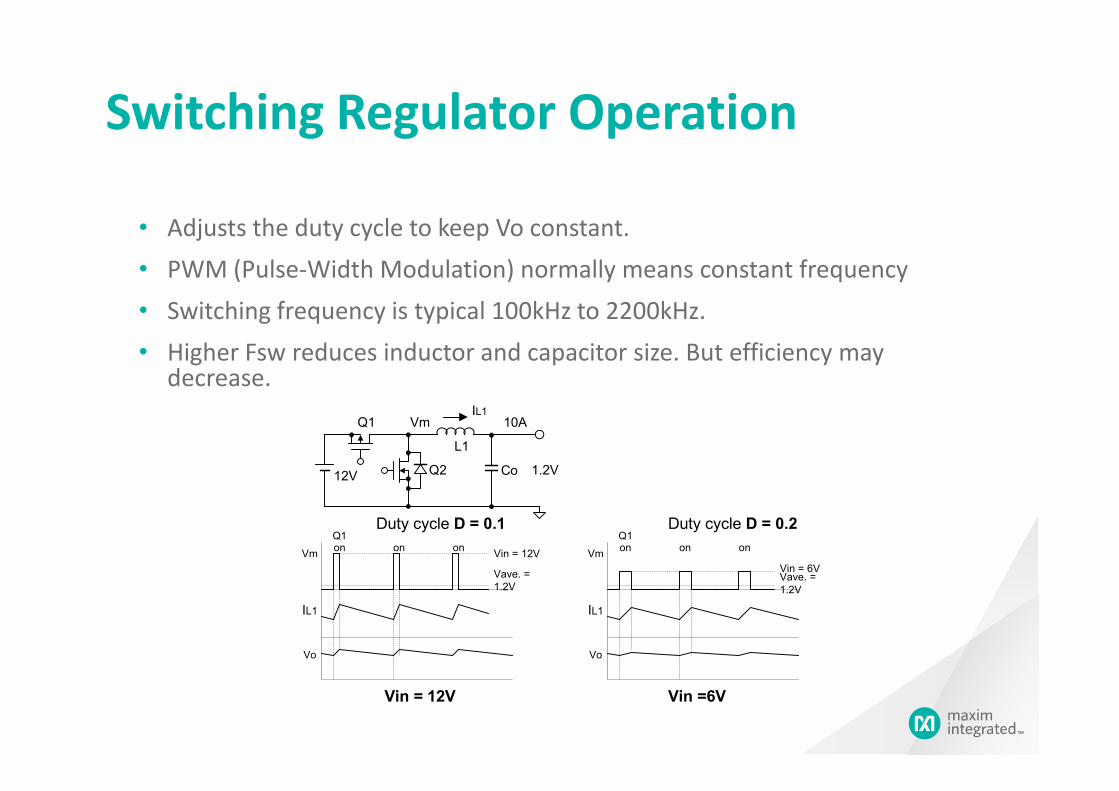
Switching Regulator Operation
• Adjusts the duty cycle to keep Vo constant.
• PWM (Pulse-Width Modulation) normally means constant frequency
• Switching frequency is typical 100kHz to 2200kHz.
• Higher Fsw reduces inductor and capacitor size. But efficiency may decrease.
Co12V Q2
L1
Q1
1.2V
10AVmIL1
Vin = 12V
Vave. =
1.2V
Vm
Q1on on on
IL1
Vin = 12V
Duty cycle D = 0.1
Vo
Vin = 6VVave. =
1.2V
Vm
Q1on on on
IL1
Vin =6V
Duty cycle D = 0.2
Vo
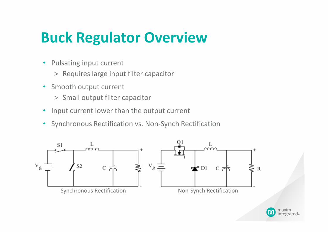
Buck Regulator Overview
• Pulsating input current
> Requires large input filter capacitor
• Smooth output current
> Small output filter capacitor
• Input current lower than the output current
• Synchronous Rectification vs. Non-Synch Rectification
Synchronous Rectification Non-Synch Rectification

Boost Regulator Overview
• Smooth input current
> The inductor filters input current spikes
• Pulsating output current
> Bigger output filter capacitor for given ripple requirement
• Input current is greater than the output current• Input current is greater than the output current
> Diode/Inductor/S1 must handle large peak currents
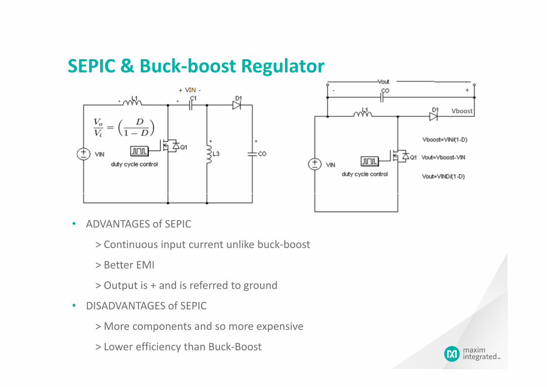
SEPIC & Buck-boost Regulator
Vboost
• ADVANTAGES of SEPIC
> Continuous input current unlike buck-boost
> Better EMI
> Output is + and is referred to ground
• DISADVANTAGES of SEPIC
> More components and so more expensive
> Lower efficiency than Buck-Boost
Agenda
1
Power Constraints in Automotive2
Solutions3
DC/DC Converter Topologies
Solutions3
4 LED Applications in Automotive
| Maxim Integrated | Company Confidential 8

Input Power Quality Overview
• Operate from 9V to 16V generally (sometimes to as low as 3V)
Crank
Maxim
Confidential
(sometimes to as low as 3V)
• Survive reverse battery & Survive 28V battery
• Survive Clamped load dump (42V)
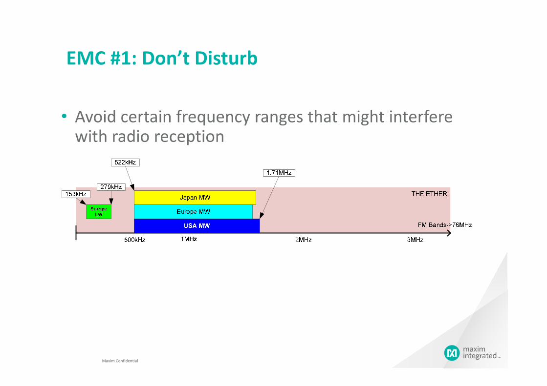
EMC #1: Don’t Disturb
• Avoid certain frequency ranges that might interfere with radio reception
Maxim Confidential

EMC #2: Don’t be disturbed
• Superimposed AC on battery, 1Vpk-pk from 50Hz to 20kHz
• Bulk current injection
Maxim
Confidential
• Bulk current injection 50mA/100mA/200mA, 1MHz to 400MHz
• RF Injection, 1MHz to 1000MHz
Agenda
1
Power Constraints in Automotive2
Solutions3
DC/DC Converter Topologies
Solutions3
4 LED Applications in Automotive
| Maxim Integrated | Company Confidential 12

Maxim Technologies to Overcome the Constraints
Solutions
42V-BCD technology
Constraints
Input power quality
| Maxim Integrated | Company Confidential 13
a)2.2MHz switching
b)Spread spectrum
c)controlled slew rates
Electromagnetic Compatibility
(don’t disturb & don’t be
disturbed)
b & don’t be disturbed)
Strange tests
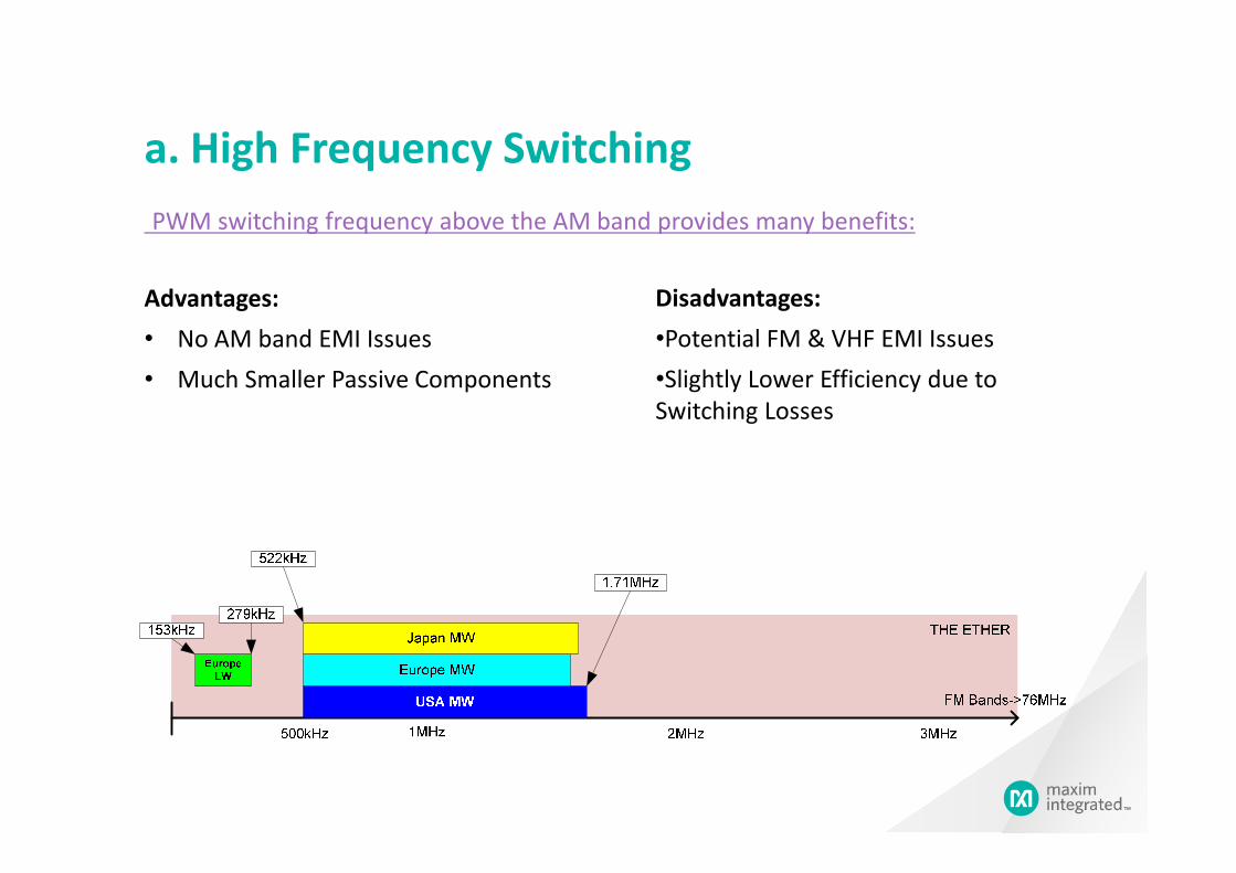
PWM switching frequency above the AM band provides many benefits:
a. High Frequency Switching
Advantages:
• No AM band EMI Issues
• Much Smaller Passive Components
Disadvantages:
•Potential FM & VHF EMI Issues
•Slightly Lower Efficiency due to
Switching Losses
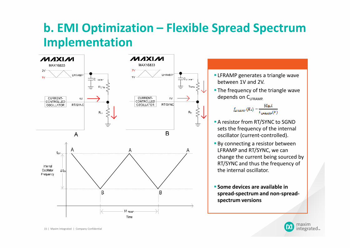
b. EMI Optimization – Flexible Spread Spectrum Implementation
LFRAMP generates a triangle wave
between 1V and 2V.
The frequency of the triangle wave
depends on CLFRAMP.
A resistor from RT/SYNC to SGND
| Maxim Integrated | Company Confidential15
A resistor from RT/SYNC to SGND
sets the frequency of the internal
oscillator (current-controlled).
By connecting a resistor between
LFRAMP and RT/SYNC, we can
change the current being sourced by
RT/SYNC and thus the frequency of
the internal oscillator.
Some devices are available in
spread-spectrum and non-spread-
spectrum versions
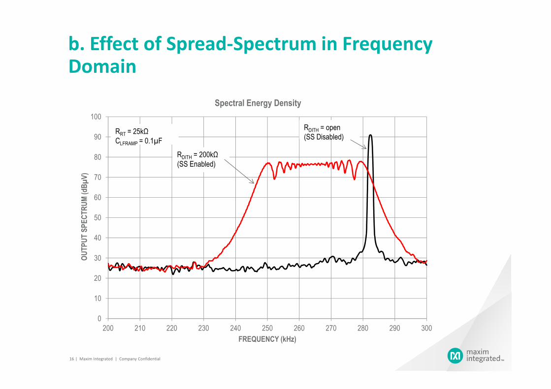
b. Effect of Spread-Spectrum in Frequency Domain
60
70
80
90
100
OUTPUT SPECTRUM (dBµV)
Spectral Energy Density
RDITH = 200kΩ
(SS Enabled)
RRT = 25kΩ
CLFRAMP = 0.1µF
RDITH = open
(SS Disabled)
| Maxim Integrated | Company Confidential16
0
10
20
30
40
50
60
200 210 220 230 240 250 260 270 280 290 300
OUTPUT SPECTRUM (dBµV)
FREQUENCY (kHz)
20−
0
Spectra Bounds vs Rise/Fall Times
Sp
ectr
al M
agnit
ud
e (d
Br)
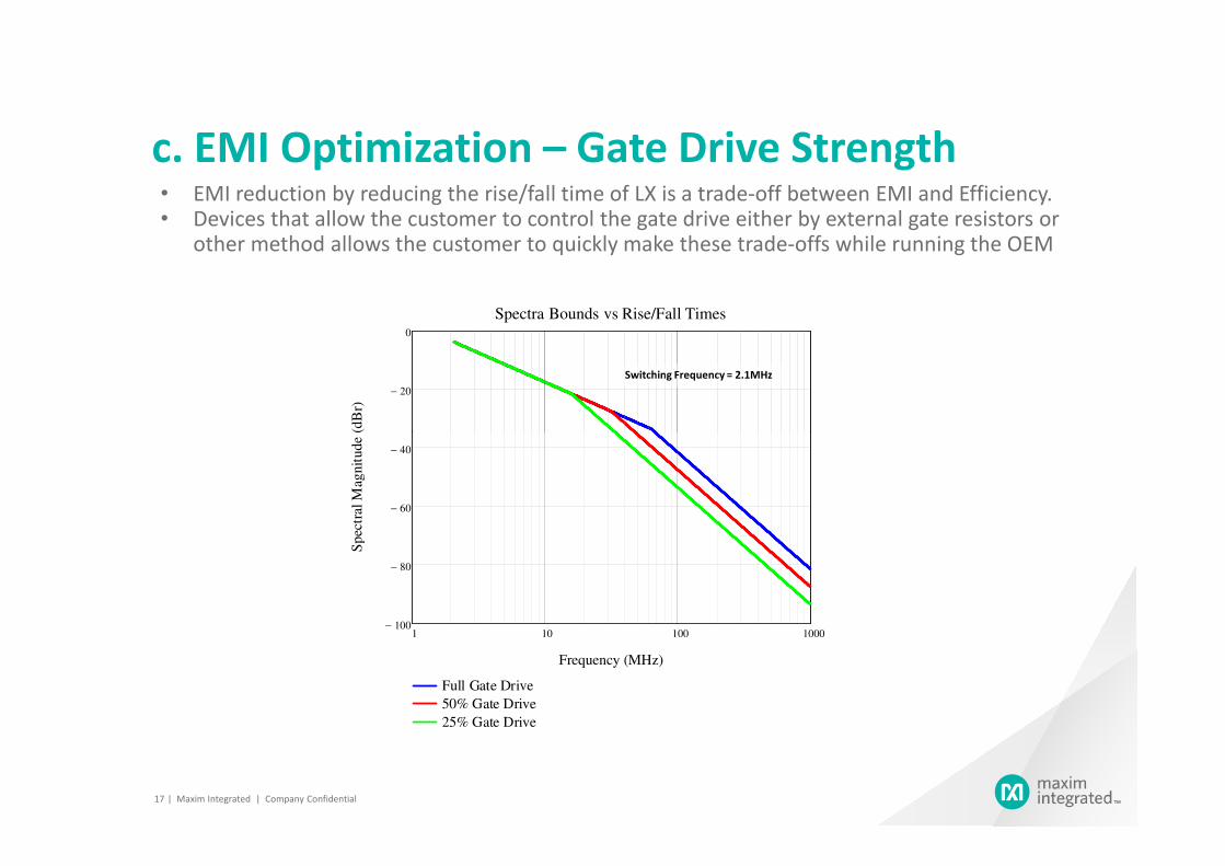
• EMI reduction by reducing the rise/fall time of LX is a trade-off between EMI and Efficiency.• Devices that allow the customer to control the gate drive either by external gate resistors or
other method allows the customer to quickly make these trade-offs while running the OEM
Switching Frequency = 2.1MHz
c. EMI Optimization – Gate Drive Strength
1 10 100 1000100−
80−
60−
40−
Full Gate Drive
50% Gate Drive
25% Gate Drive
Frequency (MHz)
Sp
ectr
al M
agnit
ud
e (d
Br)
| Maxim Integrated | Company Confidential17

Agenda
1
Power Constraints in Automotive2
Solutions3
DC/DC Converter Topologies
Solutions3
4 LED Applications in Automotive
| Maxim Integrated | Company Confidential 18
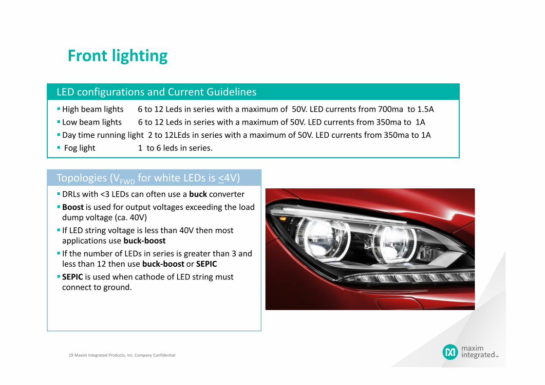
Front lighting
High beam lights 6 to 12 Leds in series with a maximum of 50V. LED currents from 700ma to 1.5A
Low beam lights 6 to 12 Leds in series with a maximum of 50V. LED currents from 350ma to 1A
Day time running light 2 to 12LEds in series with a maximum of 50V. LED currents from 350ma to 1A
Fog light 1 to 6 leds in series.
LED configurations and Current Guidelines
DRLs with <3 LEDs can often use a buck converter
Topologies (VFWD for white LEDs is <4V)
Maxim Integrated Products, Inc. Company Confidential19
DRLs with <3 LEDs can often use a buck converter
Boost is used for output voltages exceeding the load
dump voltage (ca. 40V)
If LED string voltage is less than 40V then most
applications use buck-boost
If the number of LEDs in series is greater than 3 and
less than 12 then use buck-boost or SEPIC
SEPIC is used when cathode of LED string must
connect to ground.
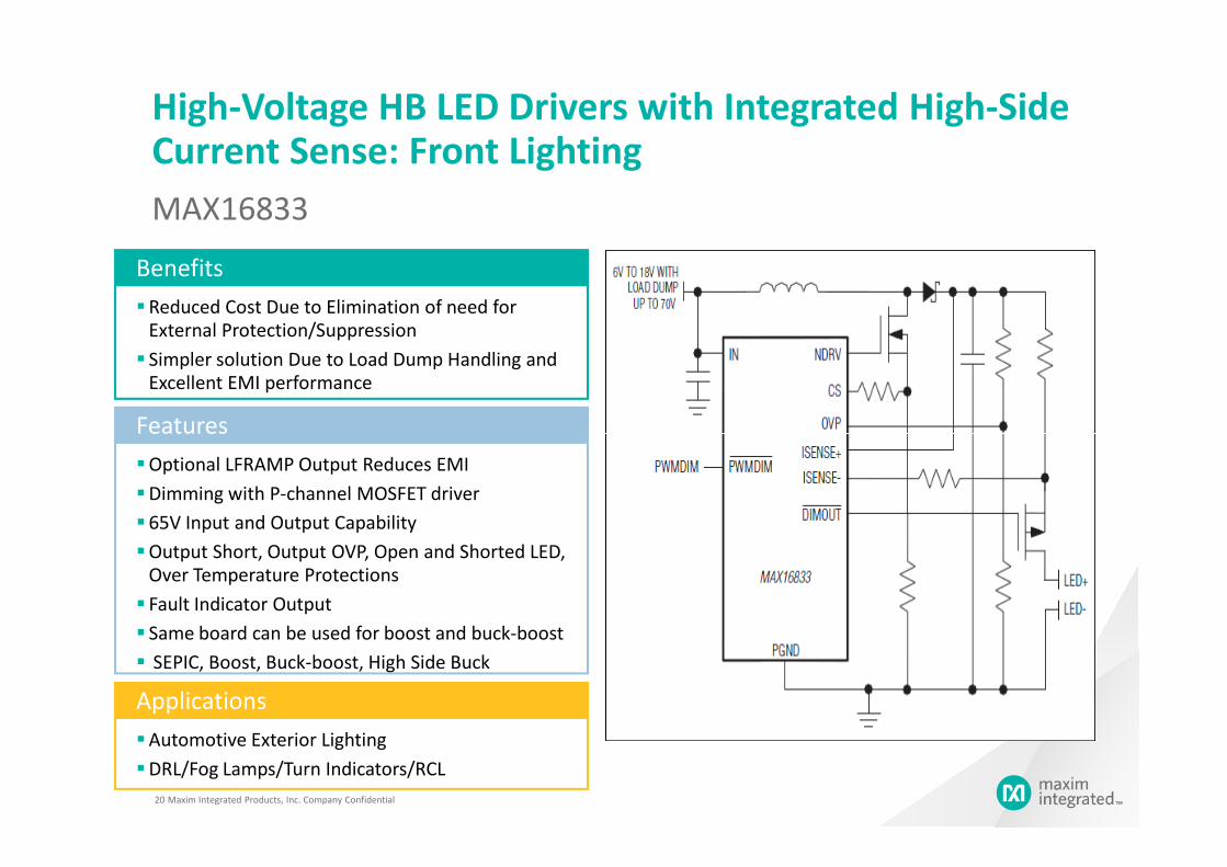
High-Voltage HB LED Drivers with Integrated High-Side Current Sense: Front Lighting
MAX16833
Reduced Cost Due to Elimination of need for
External Protection/Suppression
Simpler solution Due to Load Dump Handling and
Excellent EMI performance
Benefits
Features
Maxim Integrated Products, Inc. Company Confidential20
Optional LFRAMP Output Reduces EMI
Dimming with P-channel MOSFET driver
65V Input and Output Capability
Output Short, Output OVP, Open and Shorted LED,
Over Temperature Protections
Fault Indicator Output
Same board can be used for boost and buck-boost
SEPIC, Boost, Buck-boost, High Side Buck
Features
Automotive Exterior Lighting
DRL/Fog Lamps/Turn Indicators/RCL
Applications

Tail lightsRequirements
Multiple Linear LED drivers are required for all the
lights in the rear
Separate dimming input per channel
Brake light and tail light use the same leds with
different dimming intensities. Brake lights use 100%
dimming and tail lights use 10% dimming at
100/200Hz
When LED currents exceed 100ma then external bi-
polar is used to handle power dissipation
Maxim Integrated Products, Inc. Company Confidential21
polar is used to handle power dissipation
Turn light uses 1hz dimming at 50% duty cycle
Thermal shutdown is required
Switchers are used for currents exceeding 350ma
Parts for tail lights
MAX16839, MAX16823, MAX16836 and other linears
MAX16833, MAX16832 and MAX16834 for switchers
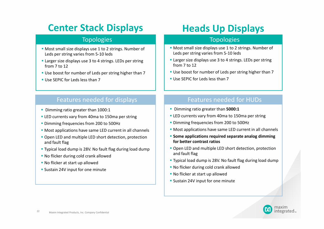
Center Stack Displays
Most small size displays use 1 to 2 strings. Number of
Leds per string varies from 5-10 leds
Larger size displays use 3 to 4 strings. LEDs per string
from 7 to 12
Use boost for number of Leds per string higher than 7
Use SEPIC for Leds less than 7
Topologies
Features needed for displays
Dimming ratio greater than 1000:1
LED currents vary from 40ma to 150ma per string
Heads Up DisplaysTopologies
Most small size displays use 1 to 2 strings. Number of
Leds per string varies from 5-10 leds
Larger size displays use 3 to 4 strings. LEDs per string
from 7 to 12
Use boost for number of Leds per string higher than 7
Use SEPIC for Leds less than 7
Dimming ratio greater than 5000:1
LED currents vary from 40ma to 150ma per string
Features needed for HUDs
Maxim Integrated Products, Inc. Company Confidential22
LED currents vary from 40ma to 150ma per string
Dimming frequencies from 200 to 500Hz
Most applications have same LED current in all channels
Open LED and multiple LED short detection, protection
and fault flag
Typical load dump is 28V. No fault flag during load dump
No flicker during cold crank allowed
No flicker at start up allowed
Sustain 24V input for one minute
LED currents vary from 40ma to 150ma per string
Dimming frequencies from 200 to 500Hz
Most applications have same LED current in all channels
Some applications required separate analog dimming
for better contrast ratios
Open LED and multiple LED short detection, protection
and fault flag
Typical load dump is 28V. No fault flag during load dump
No flicker during cold crank allowed
No flicker at start up allowed
Sustain 24V input for one minute
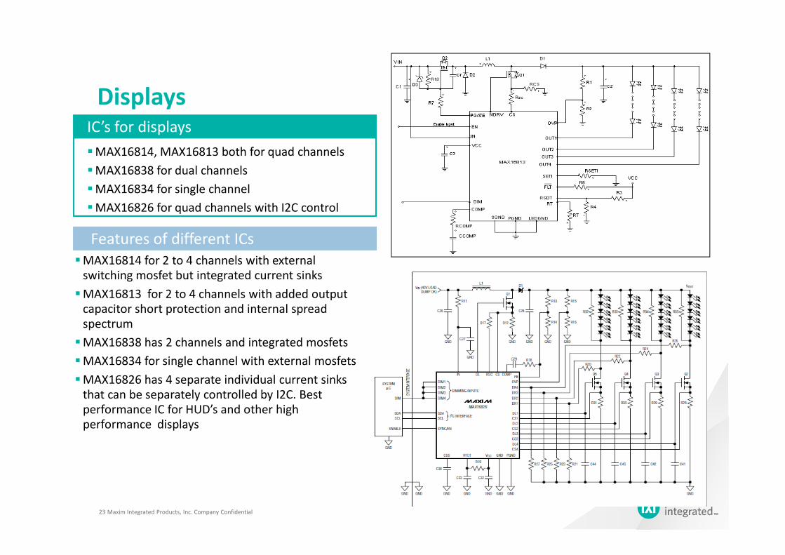
Displays
MAX16814, MAX16813 both for quad channels
MAX16838 for dual channels
MAX16834 for single channel
MAX16826 for quad channels with I2C control
IC’s for displays
Features of different ICs
MAX16814 for 2 to 4 channels with external
switching mosfet but integrated current sinks
Maxim Integrated Products, Inc. Company Confidential23
switching mosfet but integrated current sinks
MAX16813 for 2 to 4 channels with added output
capacitor short protection and internal spread
spectrum
MAX16838 has 2 channels and integrated mosfets
MAX16834 for single channel with external mosfets
MAX16826 has 4 separate individual current sinks
that can be separately controlled by I2C. Best
performance IC for HUD’s and other high
performance displays
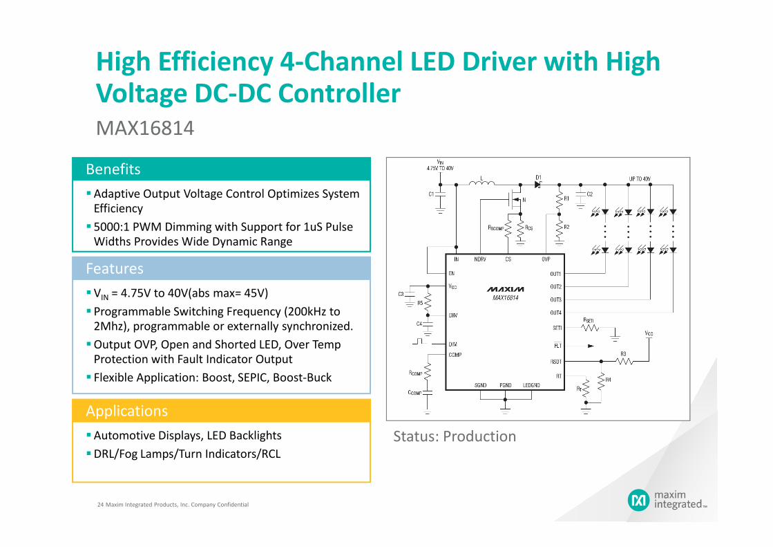
High Efficiency 4-Channel LED Driver with High Voltage DC-DC Controller
MAX16814
Adaptive Output Voltage Control Optimizes System
Efficiency
5000:1 PWM Dimming with Support for 1uS Pulse
Widths Provides Wide Dynamic Range
Benefits
Features
VIN = 4.75V to 40V(abs max= 45V)
Programmable Switching Frequency (200kHz to
2Mhz), programmable or externally synchronized.
Output OVP, Open and Shorted LED, Over Temp
Protection with Fault Indicator Output
Flexible Application: Boost, SEPIC, Boost-Buck
Features
Automotive Displays, LED Backlights
DRL/Fog Lamps/Turn Indicators/RCL
Applications
Status: Production
Maxim Integrated Products, Inc. Company Confidential24
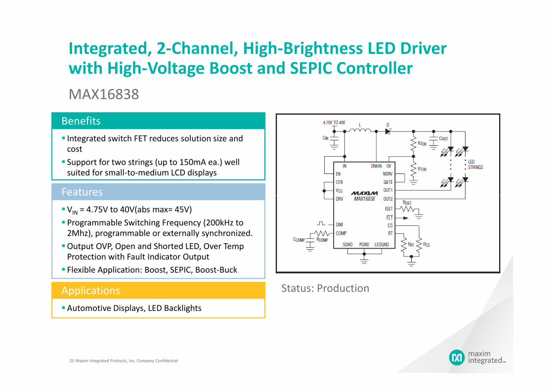
Integrated, 2-Channel, High-Brightness LED Driver with High-Voltage Boost and SEPIC Controller
MAX16838
Integrated switch FET reduces solution size and
cost
Support for two strings (up to 150mA ea.) well
suited for small-to-medium LCD displays
Benefits
Features
Maxim Integrated Products, Inc. Company Confidential25
VIN = 4.75V to 40V(abs max= 45V)
Programmable Switching Frequency (200kHz to
2Mhz), programmable or externally synchronized.
Output OVP, Open and Shorted LED, Over Temp
Protection with Fault Indicator Output
Flexible Application: Boost, SEPIC, Boost-Buck
Features
Automotive Displays, LED Backlights
Applications Status: Production

Programmable, 4-Channel LED Driver with output voltage optimization and fault detection
MAX16826
Separate individual LED current by I2C
Separate dimming control with dedicated control
pins
Benefits
Features
VIN = 4.75V to 24V(abs max = 30V)
Programmable Switching Frequency (100kHz to
1Mhz)
Output OVP, Open and Shorted LED, Over Temp
Protection with Fault Indicator Output
Flexible Application: Boost, SEPIC
Features
Automotive Displays, LCD TV LED Backlights
DRL/Fog Lamps/Turn Indicators/RCL
Applications
Status: Production
Maxim Integrated Products, Inc. Company Confidential26
Other Material
• MAXIM Automotive Product
http://www.maximintegrated.com/products/automotive/
• MAXIM Automotive HB LED Driver
http://www.maximintegrated.com/products/display/led/automotive-lighting.cfm
Maxim Integrated Products, Inc. Company Confidential27
• Website Resource
> Part selection parameter tables
> Datasheets
> Evkit datasheets
> Application notes