Lecture 10 – Finite State Recognizers and Sequence Detectors
33
Finite State Recognizers and Sequence Detectors ECE 152A – Winter 2012
Transcript of Lecture 10 – Finite State Recognizers and Sequence Detectors
Finite State Recognizers and Sequence Detectors
ECE 152A – Winter 2012
February 27, 2012 ECE 152A - Digital Design Principles 2
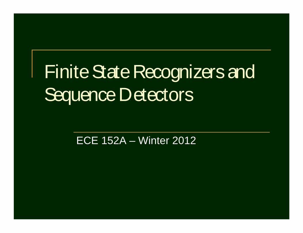
Reading Assignment
Brown and Vranesic 8 Synchronous Sequential Circuits
8.4 Design of Finite State Machines Using CAD Tools 8.4.1 Verilog Code for Moore-Type FSMs 8.4.2 Synthesis of Verilog Code 8.4.3 Simulating and Testing the Circuit 8.4.4 Alternative Styles of Verilog Code 8.4.5 Summary of Design Steps When Using CAD Tools 8.4.6 Specifying the State Assignment in Verilog Code 8.4.7 Specification of Mealy FSMs Using Verilog
February 27, 2012 ECE 152A - Digital Design Principles 3
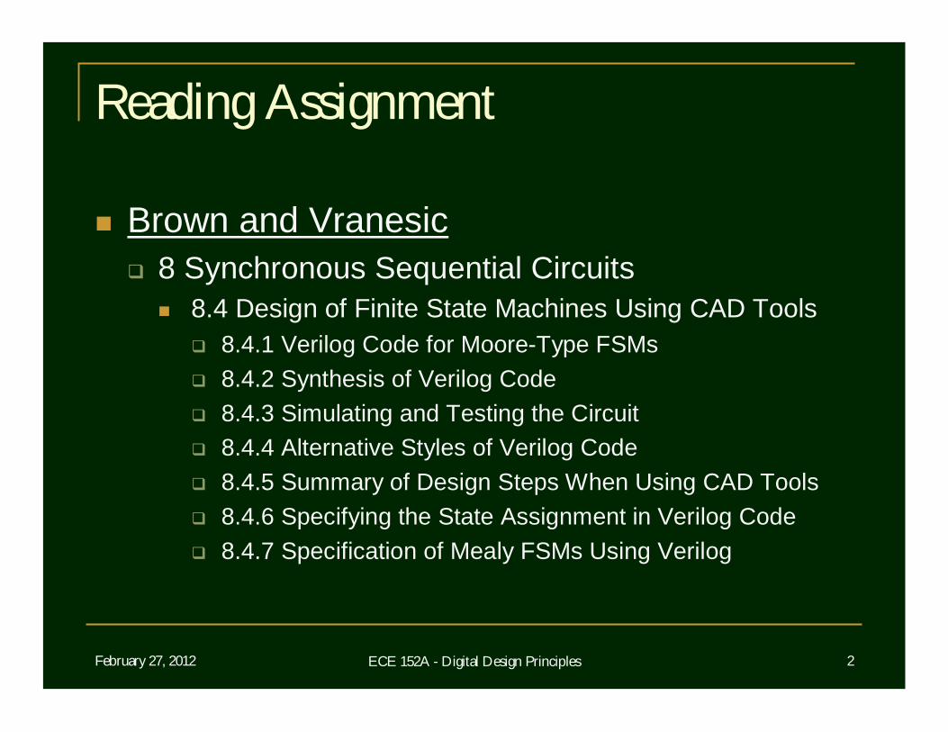
Reading Assignment
Roth 14 Derivation of State Graphs and Tables
14.1 Design of a Sequence Detector 14.2 More Complex Design Problems 14.2 Guidelines for Construction of State Graphs
February 27, 2012 ECE 152A - Digital Design Principles 4
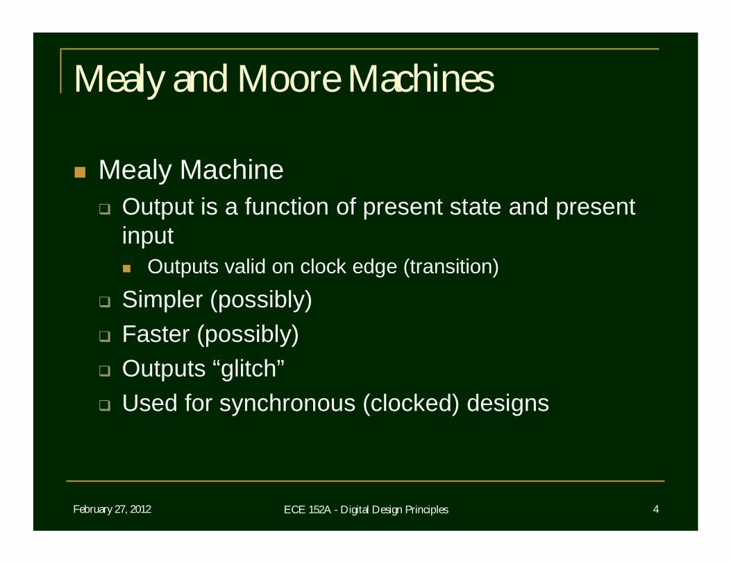
Mealy and Moore Machines
Mealy Machine Output is a function of present state and present
input Outputs valid on clock edge (transition)
Simpler (possibly) Faster (possibly) Outputs “glitch” Used for synchronous (clocked) designs
February 27, 2012 ECE 152A - Digital Design Principles 5
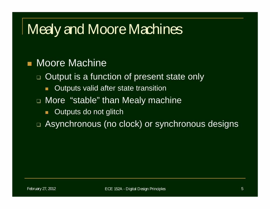
Mealy and Moore Machines
Moore Machine Output is a function of present state only
Outputs valid after state transition More “stable” than Mealy machine
Outputs do not glitch Asynchronous (no clock) or synchronous designs
February 27, 2012 ECE 152A - Digital Design Principles 6
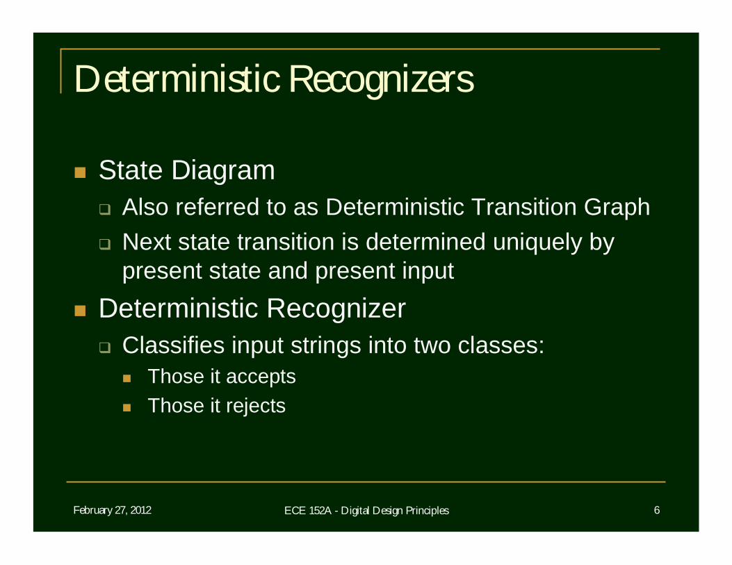
Deterministic Recognizers
State Diagram Also referred to as Deterministic Transition Graph Next state transition is determined uniquely by
present state and present input Deterministic Recognizer Classifies input strings into two classes:
Those it accepts Those it rejects
February 27, 2012 ECE 152A - Digital Design Principles 7
Deterministic Recognizers
Sequential Lock Analogy Accepted string corresponds to of the combination
of the lock Accepted string opens the lock Rejected string leaves the lock closed
Provides a basis for general purpose, finite state machine (FSM) design Controllers, peripheral interfaces, etc.
February 27, 2012 ECE 152A - Digital Design Principles 8
Deterministic Recognizers
Definition of states Starting (or initial) state must be defined The states whose assigned output is 1 are
referred to as accepting (or terminal) states The states whose assigned output is 0 are called
rejecting (or nonterminal) states Above definition of states and control implies
a Moore finite-state machine With the requirement of a defined initial state
February 27, 2012 ECE 152A - Digital Design Principles 9
Deterministic Recognizers
Definition of acceptance and recognition A string is accepted by a machine if and only if the
state that the machine enters after having read the rightmost symbol is an accepting state Otherwise, the string is rejected
The set of strings recognized by a machine thus consists of all the input strings that take the machine from its starting state to an accepting state
February 27, 2012 ECE 152A - Digital Design Principles 10
Regular Expressions
Concerned here with the characterization of sets of strings recognized by finite automata
A compact language for describing such sets of strings is known as the language of regular expressions Example 01(01)* describes the set consisting of
those strings that can be formed by concatenating one or more 01 strings 01 + 0101 + 010101 + 01010101 + ...
February 27, 2012 ECE 152A - Digital Design Principles 11
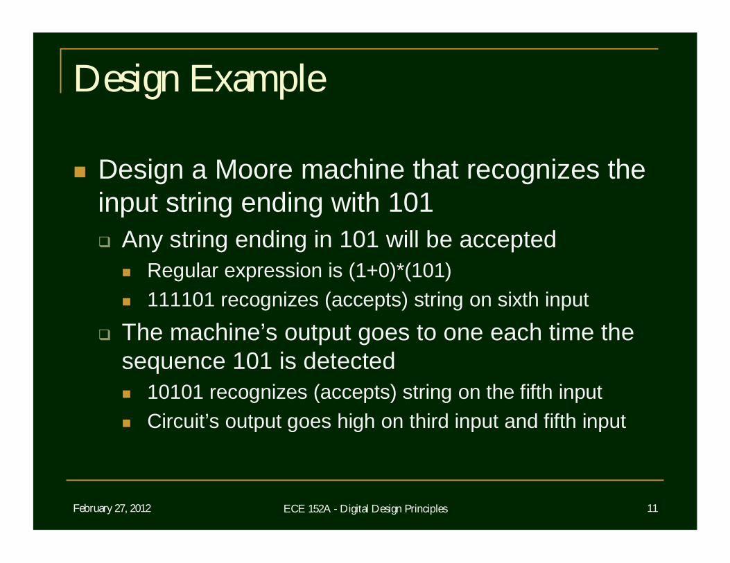
Design Example
Design a Moore machine that recognizes the input string ending with 101 Any string ending in 101 will be accepted
Regular expression is (1+0)*(101) 111101 recognizes (accepts) string on sixth input
The machine’s output goes to one each time the sequence 101 is detected 10101 recognizes (accepts) string on the fifth input Circuit’s output goes high on third input and fifth input
February 27, 2012 ECE 152A - Digital Design Principles 12
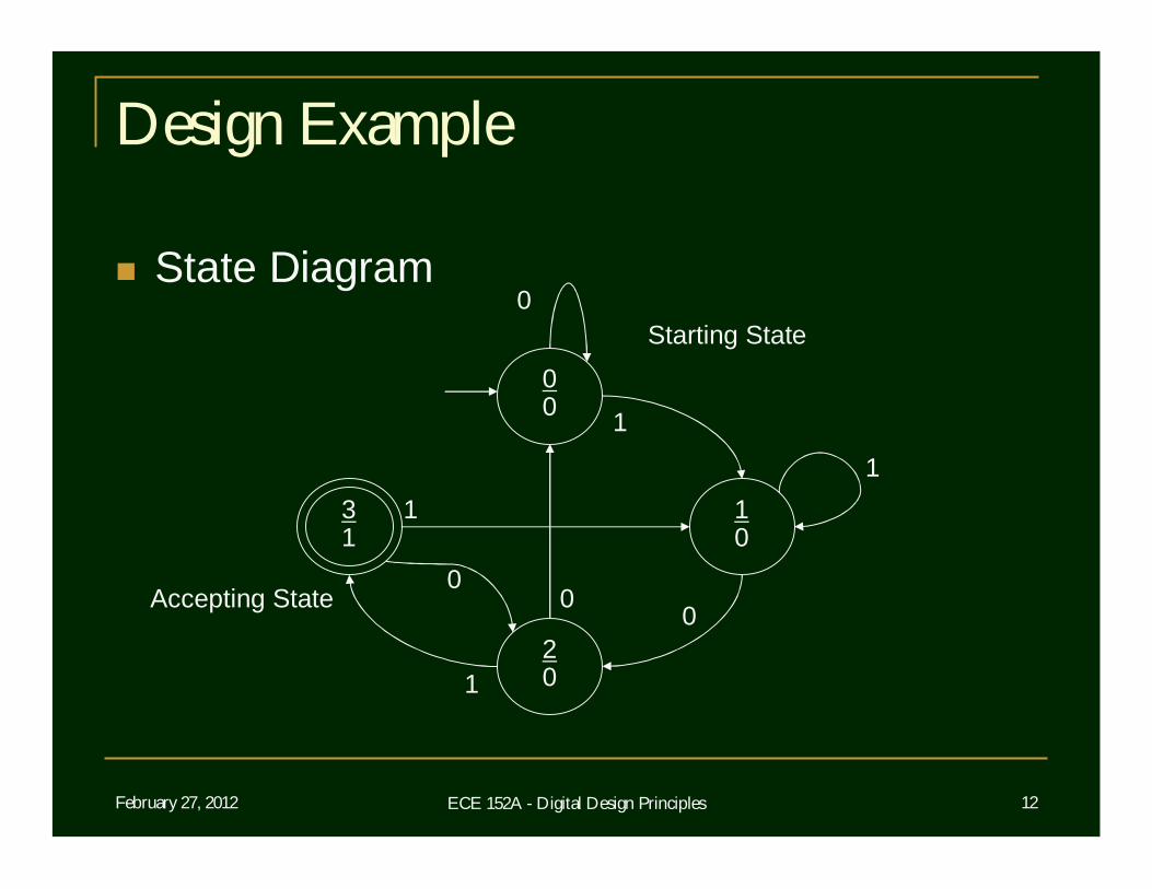
Design Example
State Diagram
00
20
10
31
0
00
0
1
1
1
1
Starting State
Accepting State
February 27, 2012 ECE 152A - Digital Design Principles 13
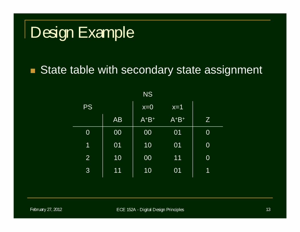
Design Example
State table with secondary state assignment
01100102
10110113
00110011
00100000
ZA+B+A+B+AB
x=1x=0PS
NS
February 27, 2012 ECE 152A - Digital Design Principles 14
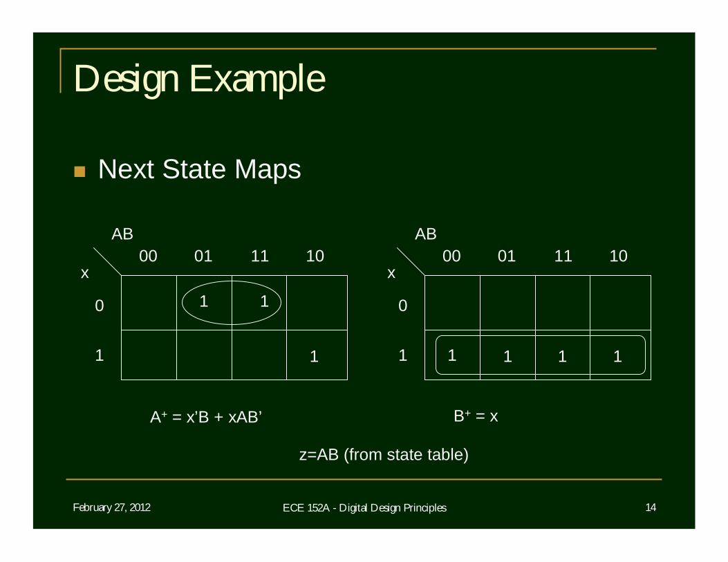
Design Example
Next State Maps
AB
x00 01
0
1
11 10AB
x00 01
0
1
11 10
1 11
A+ = x’B + xAB’ B+ = x
1 1
11
z=AB (from state table)
February 27, 2012 ECE 152A - Digital Design Principles 15
Design Example
Design can now be implemented In discrete hardware, directly from next state
maps with D flip-flops or using excitation tables for T or JK flip-flops
In Verilog directly from state table Verilog implementation follows
February 27, 2012 ECE 152A - Digital Design Principles 16
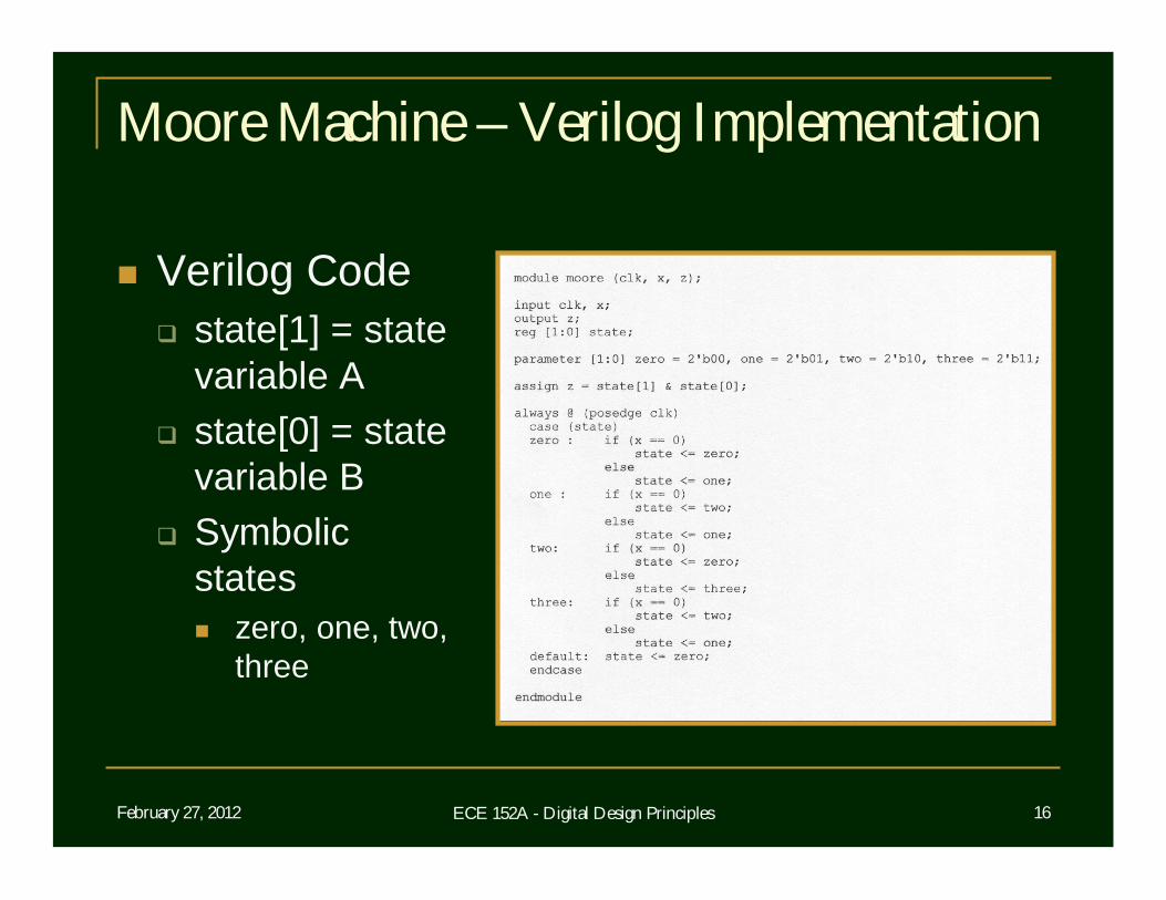
Moore Machine – Verilog Implementation
Verilog Code state[1] = state
variable A state[0] = state
variable B Symbolic
states zero, one, two,
three
February 27, 2012 ECE 152A - Digital Design Principles 17
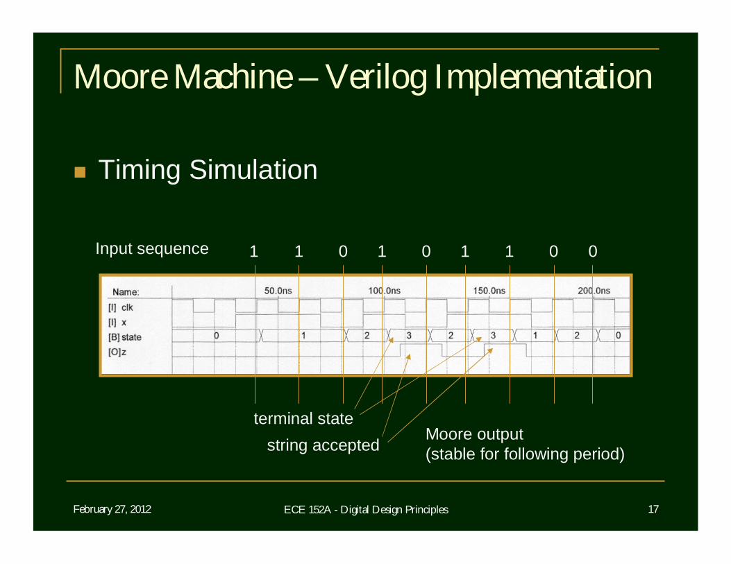
Moore Machine – Verilog Implementation
Timing Simulation
Input sequence 1 1 0 1 0 1 1 0 0
terminal statestring accepted
Moore output (stable for following period)
February 27, 2012 ECE 152A - Digital Design Principles 18
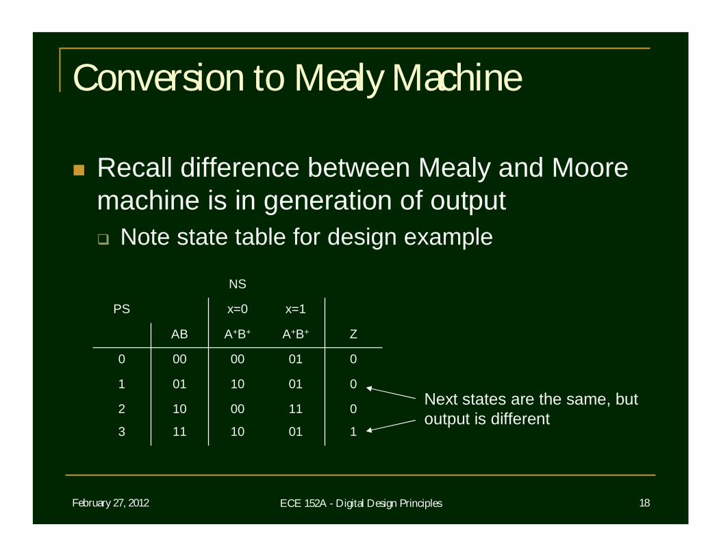
Conversion to Mealy Machine
Recall difference between Mealy and Moore machine is in generation of output Note state table for design example
01100102
10110113
00110011
00100000
ZA+B+A+B+AB
x=1x=0PS
NS
Next states are the same, butoutput is different
February 27, 2012 ECE 152A - Digital Design Principles 19
Conversion to Mealy Machine
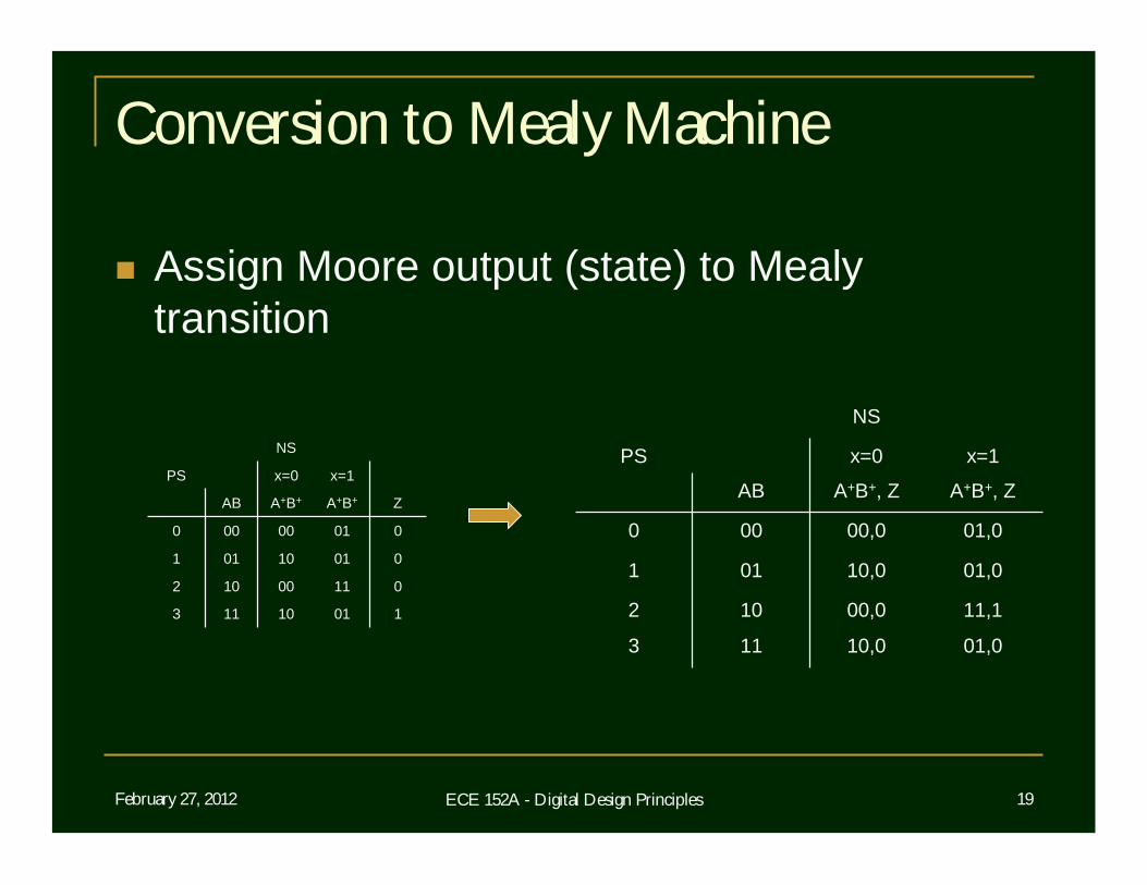
Assign Moore output (state) to Mealy transition
01100102
10110113
00110011
00100000
ZA+B+A+B+AB
x=1x=0PS
NS
11,100,0102
01,010,0113
01,010,0011
01,000,0000
A+B+, ZA+B+, ZAB
x=1x=0PS
NS
February 27, 2012 ECE 152A - Digital Design Principles 20
Conversion to Mealy Machine
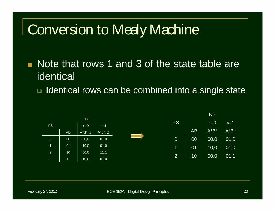
Note that rows 1 and 3 of the state table are identical Identical rows can be combined into a single state
11,100,0102
01,010,0113
01,010,0011
01,000,0000
A+B+, ZA+B+, ZAB
x=1x=0PS
NS
01,100,0102
01,010,0011
01,000,0000
A+B+A+B+AB
x=1x=0PS
NS
February 27, 2012 ECE 152A - Digital Design Principles 21
Conversion to Mealy Machine
Because outputs in a Mealy machine are associated with the transition and not the next state, states 1 and 3 can be combined Call combined state “state 1” and eliminate state 3
New state 1 entered with output of 0 from old state 1 New state 1 entered with output of 1 from unchanged
state 2 Technically, no longer a finite state recognizer
because of Mealy implementation No longer an acceptance “state”
February 27, 2012 ECE 152A - Digital Design Principles 22
Conversion to Mealy Machine
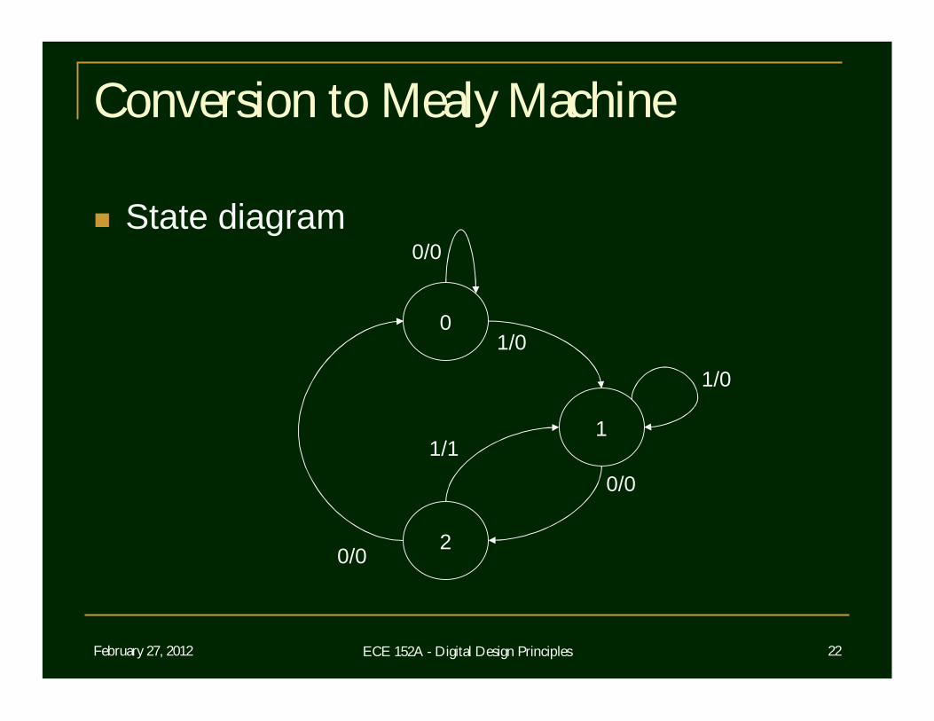
State diagram
0
2
1
0/0
0/0
0/0
1/0
1/0
1/1
February 27, 2012 ECE 152A - Digital Design Principles 23
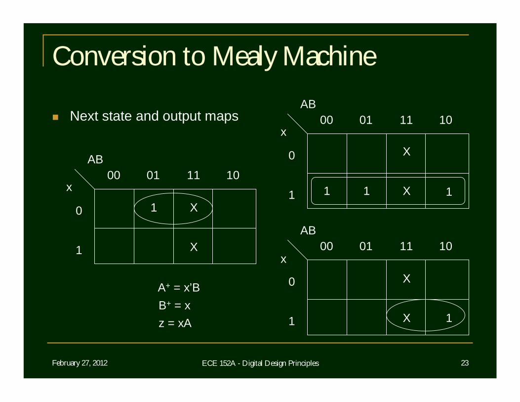
Conversion to Mealy Machine
Next state and output maps
AB
x00 01
0
1
11 10
1
AB
x00 01
0
1
11 10
AB
x00 01
0
1
11 10
11
1
A+ = x’BB+ = xz = xA
X1
X
X
X
X
X
February 27, 2012 ECE 152A - Digital Design Principles 24
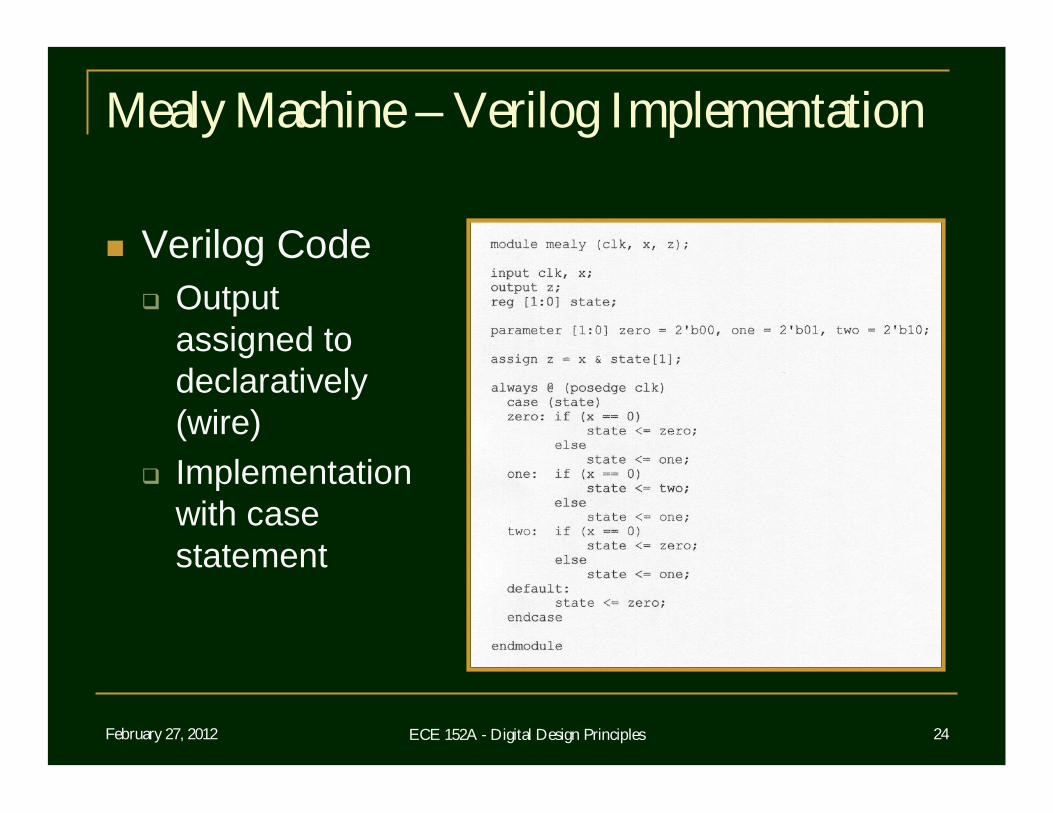
Mealy Machine – Verilog Implementation
Verilog Code Output
assigned to declaratively (wire)
Implementation with case statement
February 27, 2012 ECE 152A - Digital Design Principles 25
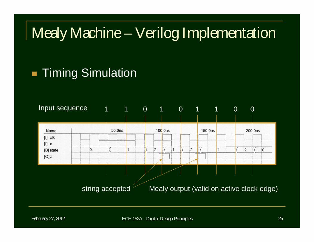
Mealy Machine – Verilog Implementation
Timing Simulation
Input sequence 1 1 0 1 0 1 1 0 0
string accepted Mealy output (valid on active clock edge)
February 27, 2012 ECE 152A - Digital Design Principles 26
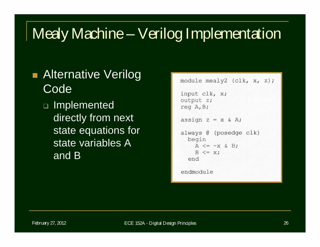
Mealy Machine – Verilog Implementation
Alternative Verilog Code Implemented
directly from next state equations for state variables A and B
February 27, 2012 ECE 152A - Digital Design Principles 27
Mealy Machine – Verilog Implementation
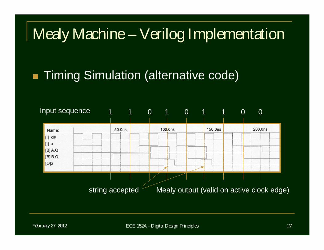
Timing Simulation (alternative code)
Input sequence 1 1 0 1 0 1 1 0 0
string accepted Mealy output (valid on active clock edge)
February 27, 2012 ECE 152A - Digital Design Principles 28
Conversion from Mealy to Moore
0
2
1
0/0
0/0
1/0
1/0
1/1
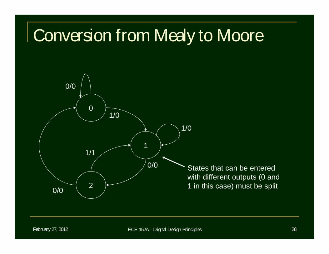
States that can be entered with different outputs (0 and1 in this case) must be split
0/0
February 27, 2012 ECE 152A - Digital Design Principles 29
Conversion from Mealy to Moore
0
2
1
0/0
0/0
1/0
1/0
1/1
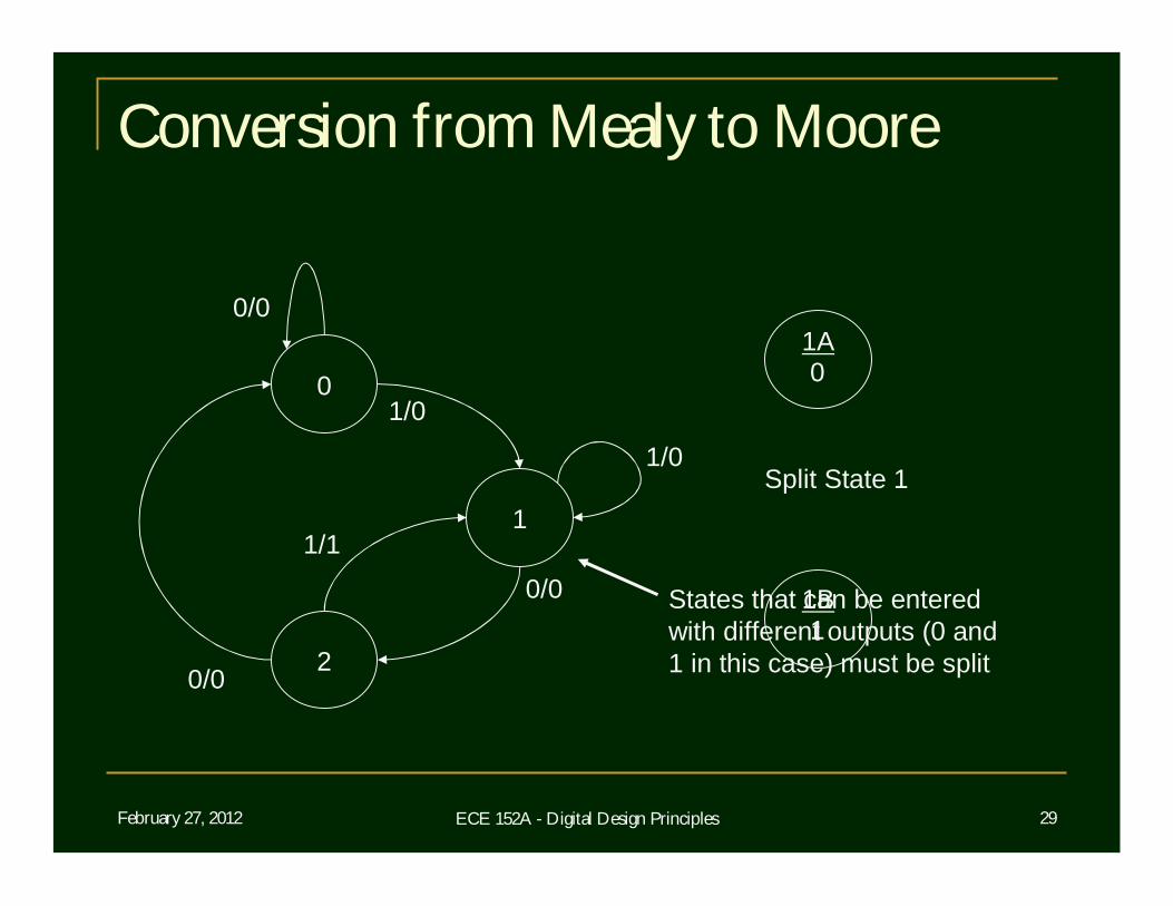
1A
1B
0
1
Split State 1
0/0
States that can be entered with different outputs (0 and1 in this case) must be split
February 27, 2012 ECE 152A - Digital Design Principles 30
Conversion from Mealy to Moore
0
2
1
0/0
0/0
1/0
1/0
1/1
1A
1B
0
1 1/0
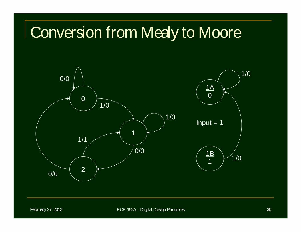
Input = 1
0/0
1/0
February 27, 2012 ECE 152A - Digital Design Principles 31
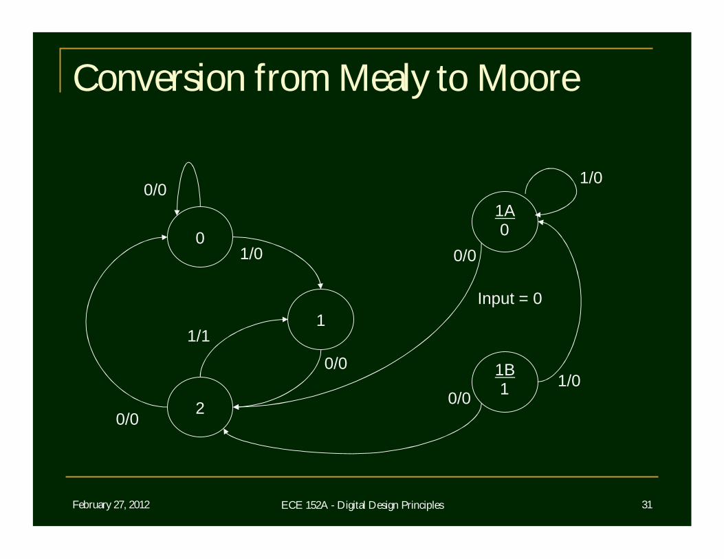
Conversion from Mealy to Moore
0
2
1
0/0
0/0
1/0
1/0
1/1
1A
1B
0
1 1/00/0
Input = 0
0/0
0/0
February 27, 2012 ECE 152A - Digital Design Principles 32
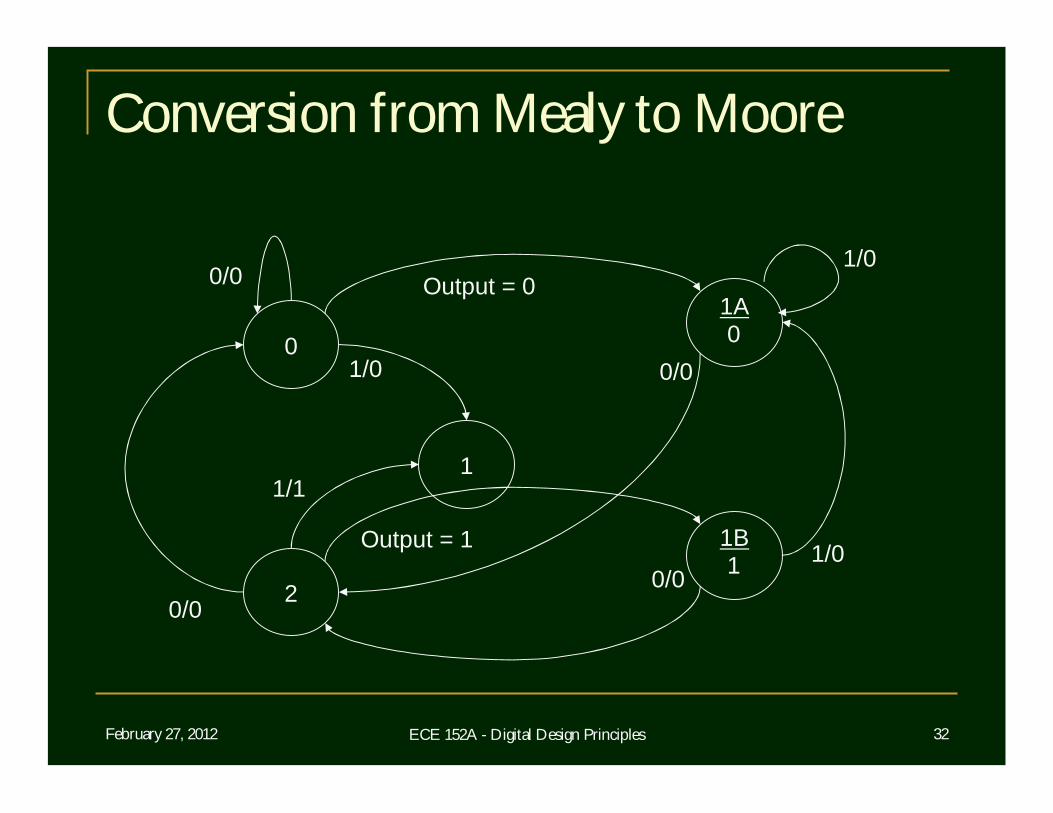
Conversion from Mealy to Moore
0
2
1
0/0
0/0
0/0
1/0
1/0
1/1
1A
1B
0
1 1/00/0
Output = 0
Output = 1
February 27, 2012 ECE 152A - Digital Design Principles 33
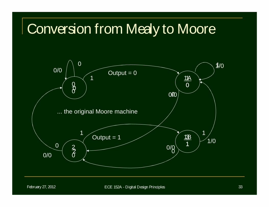
Conversion from Mealy to Moore
0
2
0
1
3
0
1
0
0
0
0
0
1
11
1
... the original Moore machine
0
2
0/0
0/0
0/0
1/0
1A
1B
0
1 1/00/0
Output = 0
Output = 1