LC2650 Level controller - stimexeng.comstimexeng.com/download/SpiraxSarco/Котельное... ·...
64
LC2650 Level controller Installation and Maintenance Instructions Printed in the UK © Copyright 2012 IM-P402-128 AB Issue 4 4028051/4 OK LC2650 100 50 0 % SP PV AL 1. Safety information 2. General product and delivery information 3. System overview 4. Mechanical installation 5. Electrical installation 6. Commissioning - Quick set-up - Full 7. Communications 8. Maintenance 9. Fault finding 10. Technical information - Default settings 11. Appendix - Summary of the Modbus protocol 12. Menu map
-
Upload
nguyendung -
Category
Documents
-
view
215 -
download
0
Transcript of LC2650 Level controller - stimexeng.comstimexeng.com/download/SpiraxSarco/Котельное... ·...

IM-P402-128 AB Issue 4 1
LC2650 Level controller
Installation and Maintenance Instructions
Printed in the UK © Copyright 2012
IM-P402-128AB Issue 4
4028051/4
OK
LC2650
100
50
0%
SP PV AL
1. Safety information
2. General product and delivery information
3. System overview
4. Mechanical installation
5. Electrical installation
6. Commissioning - Quick set-up - Full
7. Communications
8. Maintenance
9. Fault finding
10. Technical information - Default settings
11. Appendix - Summary of the Modbus protocol
12. Menu map
IM-P402-128 AB Issue 42
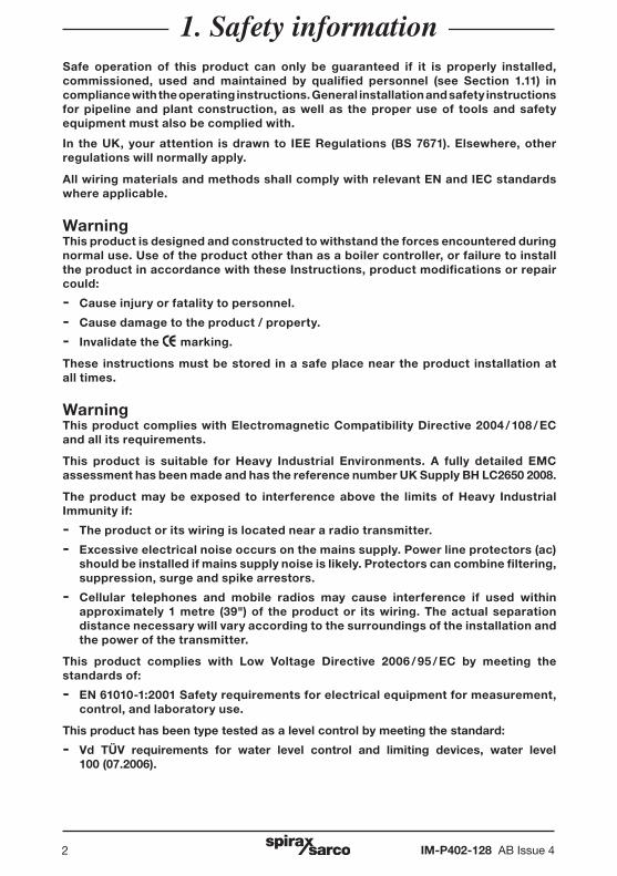
1. Safety informationSafe operation of this product can only be guaranteed if it is properly installed, commissioned, used and maintained by qualified personnel (see Section 1.11) in compliance with the operating instructions. General installation and safety instructions for pipeline and plant construction, as well as the proper use of tools and safety equipment must also be complied with.
In the UK, your attention is drawn to IEE Regulations (BS 7671). Elsewhere, other regulations will normally apply.
All wiring materials and methods shall comply with relevant EN and IEC standards where applicable.
WarningThis product is designed and constructed to withstand the forces encountered during normal use. Use of the product other than as a boiler controller, or failure to install the product in accordance with these Instructions, product modifications or repair could:
- Cause injury or fatality to personnel.
- Cause damage to the product / property.
- Invalidate the marking.
These instructions must be stored in a safe place near the product installation at all times.
WarningThis product complies with Electromagnetic Compatibility Directive 2004 / 108 / EC and all its requirements.
This product is suitable for Heavy Industrial Environments. A fully detailed EMC assessment has been made and has the reference number UK Supply BH LC2650 2008.
The product may be exposed to interference above the limits of Heavy Industrial Immunity if:
- The product or its wiring is located near a radio transmitter.
- Excessive electrical noise occurs on the mains supply. Power line protectors (ac) should be installed if mains supply noise is likely. Protectors can combine filtering, suppression, surge and spike arrestors.
- Cellular telephones and mobile radios may cause interference if used within approximately 1 metre (39") of the product or its wiring. The actual separation distance necessary will vary according to the surroundings of the installation and the power of the transmitter.
This product complies with Low Voltage Directive 2006 / 95 / EC by meeting the standards of:
- EN 61010-1:2001 Safety requirements for electrical equipment for measurement, control, and laboratory use.
This product has been type tested as a level control by meeting the standard:
- Vd TÜV requirements for water level control and limiting devices, water level 100 (07.2006).
IM-P402-128 AB Issue 4 3
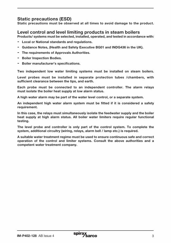
Static precautions (ESD)Static precautions must be observed at all times to avoid damage to the product.
Level control and level limiting products in steam boilersProducts/ systems must be selected, installed, operated, and tested in accordance with:
- Local or National standards and regulations.
- Guidance Notes, (Health and Safety Executive BG01 and INDG436 in the UK).
- The requirements of Approvals Authorities.
- Boiler Inspection Bodies.
- Boiler manufacturer’s specifications.
Two independent low water limiting systems must be installed on steam boilers.
Level probes must be installed in separate protection tubes /chambers, withsufficient clearance between the tips, and earth.
Each probe must be connected to an independent controller. The alarm relaysmust isolate the boiler heat supply at low alarm status.
A high water alarm may be part of the water level control, or a separate system.
An independent high water alarm system must be fitted if it is considered a safety requirement.
In this case, the relays must simultaneously isolate the feedwater supply and the boiler heat supply at high alarm status. All boiler water limiters require regular functional testing.
The level probe and controller is only part of the control system. To complete thesystem, additional circuitry (wiring, relays, alarm bell / lamp etc.) is required.
A suitable water treatment regime must be used to ensure continuous safe and correct operation of the control and limiter systems. Consult the above authorities and a competent water treatment company.

IM-P402-128 AB Issue 44
Symbols
Equipment protected throughout by double insulation or reinforced insulation.
Functional earth (ground) terminal, to enable the product to function correctly. Not used to provide electrical safety.
Clean earth / ground.
Safety earth.
Caution, risk of electric shock.
Caution, risk of danger, refer to accompanying documentation.
Optically isolated current source or sink.
Caution, Electrostatic Discharge (ESD) sensitive circuit. Do not touch or handle without proper electrostatic discharge precautions.
ac, alternating current.
IM-P402-128 AB Issue 4 5
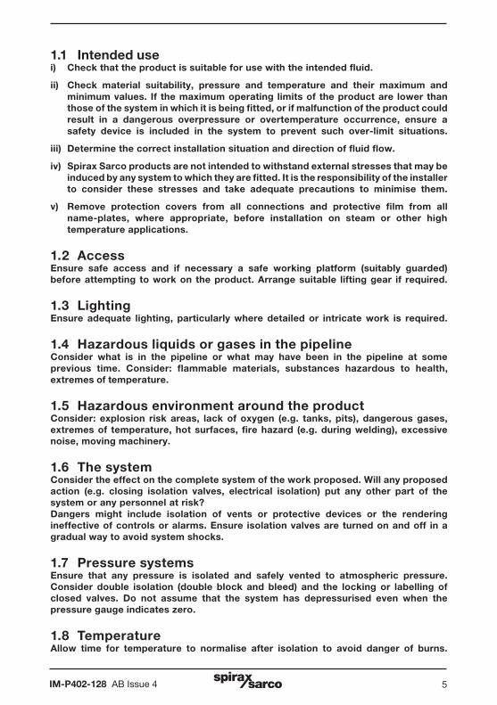
1.1 Intended usei) Check that the product is suitable for use with the intended fluid.
ii) Check material suitability, pressure and temperature and their maximum and minimum values. If the maximum operating limits of the product are lower than those of the system in which it is being fitted, or if malfunction of the product could result in a dangerous overpressure or overtemperature occurrence, ensure a safety device is included in the system to prevent such over-limit situations.
iii) Determine the correct installation situation and direction of fluid flow.
iv) Spirax Sarco products are not intended to withstand external stresses that may be induced by any system to which they are fitted. It is the responsibility of the installer to consider these stresses and take adequate precautions to minimise them.
v) Remove protection covers from all connections and protective film from all name-plates, where appropriate, before installation on steam or other high temperature applications.
1.2 AccessEnsure safe access and if necessary a safe working platform (suitably guarded) before attempting to work on the product. Arrange suitable lifting gear if required.
1.3 LightingEnsure adequate lighting, particularly where detailed or intricate work is required.
1.4 Hazardous liquids or gases in the pipelineConsider what is in the pipeline or what may have been in the pipeline at some previous time. Consider: flammable materials, substances hazardous to health, extremes of temperature.
1.5 Hazardous environment around the productConsider: explosion risk areas, lack of oxygen (e.g. tanks, pits), dangerous gases, extremes of temperature, hot surfaces, fire hazard (e.g. during welding), excessive noise, moving machinery.
1.6 The systemConsider the effect on the complete system of the work proposed. Will any proposed action (e.g. closing isolation valves, electrical isolation) put any other part of the system or any personnel at risk? Dangers might include isolation of vents or protective devices or the rendering ineffective of controls or alarms. Ensure isolation valves are turned on and off in a gradual way to avoid system shocks.
1.7 Pressure systems Ensure that any pressure is isolated and safely vented to atmospheric pressure. Consider double isolation (double block and bleed) and the locking or labelling of closed valves. Do not assume that the system has depressurised even when the pressure gauge indicates zero.
1.8 TemperatureAllow time for temperature to normalise after isolation to avoid danger of burns.
IM-P402-128 AB Issue 46
1.9 Tools and consumablesBefore starting work ensure that you have suitable tools and / or consumables available. Use only genuine Spirax Sarco replacement parts.
1.10 Protective clothingConsider whether you and / or others in the vicinity require any protective clothing to protect against the hazards of, for example, chemicals, high / low temperature, radiation, noise, falling objects, and dangers to eyes and face.
1.11 Permits to workAll work must be carried out or be supervised by a suitably competent person.Installation and operating personnel should be trained in the correct use of the product according to the Installation and Maintenance Instructions.Where a formal 'permit to work' system is in force it must be complied with. Where there is no such system, it is recommended that a responsible person should know what work is going on and, where necessary, arrange to have an assistant whose primary responsibility is safety.Post 'warning notices' if necessary.
1.12 HandlingManual handling of large and / or heavy products may present a risk of injury. Lifting, pushing, pulling, carrying or supporting a load by bodily force can cause injury particularly to the back. You are advised to assess the risks taking into account the task, the individual, the load and the working environment and use the appropriate handling method depending on the circumstances of the work being done.
1.13 Residual hazardsIn normal use the external surface of the product may be very hot. Many products are not self-draining. Take due care when dismantling or removing the product from an installation.
1.14 FreezingProvision must be made to protect products which are not self-draining against frost damage in environments where they may be exposed to temperatures below freezing point.
1.15 DisposalOn disposal of the unit or component, appropriate precautions should be taken in accordance with Local / National regulations.
Unless otherwise stated in the Installation and Maintenance Instructions this product is recyclable and no ecological hazard is anticipated with its disposal providing due care is taken.
1.16 Returning productsCustomers and stockists are reminded that under EC Health, Safety and Environment Law, when returning products to Spirax Sarco they must provide information on any hazards and the precautions to be taken due to contamination residues or mechanical damage which may present a health, safety or environmental risk. This information must be provided in writing including Health and Safety data sheets relating to any substances identified as hazardous or potentially hazardous.

IM-P402-128 AB Issue 4 7
2. General product and delivery information
2.1 General descriptionThe Spirax Sarco LC2650 is a level controller for conductive liquids. It has two alarm channels that can be independently configured high or low.
Warning: The minimum conductivity when used with the LP20 / PA20 is 5 μS/cm or 5 ppm.
The product can be panel, DIN rail, or chassis mounted and is powered by a 99 - 264 Vac mains supply.
2.2 Front panel
OK
LC2650
100
50
0%
SP PV AL
Fig. 1 Front panel and keypad definitions
Scroll down menus /sub-menus. Decrease digits.
Scroll up menus / sub-menus. Increase digits.
Enter sub-menus and shift right to the next digit when the parameter or digit is flashing.
Enters parameters when the parameter or digit is flashing. Hold down for 5 seconds to enter commissioning mode.
Exit sub-menus and shift left to the next digit when the parameter or digit is flashing.
Graphic display
2.3 Using the buttonsThe and buttons are used to:
- scroll up and down through the menus and sub-menus.
- increase or decrease digits when in a menu or sub-menu.
The and buttons are used to:
- exit and enter sub-menus.
- shift left and right to a flashing digit or parameter when in a menu or sub-menu.
The OK button is used to:
- enter your choice of digit or parameter, when the digit or parameter is flashing.
- enter the commissioning mode (press and hold for five seconds).
Commissioning sets the product parameters, and allows the user to set and test the outputs, and to change the pass code - see Section 6.
Data to be edited is always displayed on the bottom right of the screen. Pressing the OK button will enter new data. Pressing the and buttons will scroll through the available data and the previously entered selection will flash.
The front panel has an LCD graphics display and five-button keypad.
IM-P402-128 AB Issue 48
100%
50%
0%SP PV AL
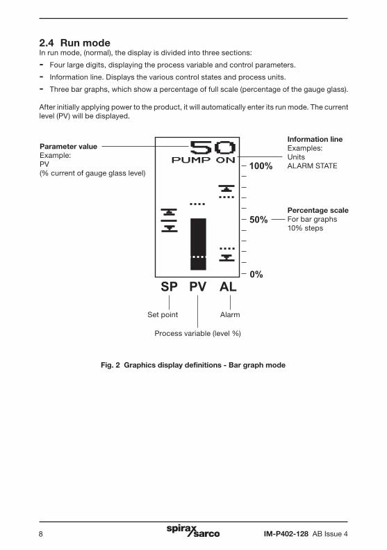
2.4 Run modeIn run mode, (normal), the display is divided into three sections:
- Four large digits, displaying the process variable and control parameters.
- Information line. Displays the various control states and process units.
- Three bar graphs, which show a percentage of full scale (percentage of the gauge glass).
After initially applying power to the product, it will automatically enter its run mode. The current level (PV) will be displayed.
Set point
Information lineExamples:UnitsALARM STATE
Percentage scaleFor bar graphs10% steps
Alarm
Process variable (level %)
Fig. 2 Graphics display definitions - Bar graph mode
Parameter valueExample:PV(% current of gauge glass level)

IM-P402-128 AB Issue 4 9
PV
AL
PV
AL
Fig. 3 PV (level %) bar graph definitions
Fig. 5 Alarms bar graph definitions
Highest process variable reachedThis can be reset by entering the commissioning mode (Pass code protected).
Lowest process variableThis can be reset by entering the commissioning mode (Pass code protected).
Current process variableGraphical representation of the process variable in terms of percentage of full scale.
High alarm level
Low alarm hysteresis
High alarm hysteresis
Low alarm level
SPSP
High limit or top of proportional band
Low limit or bottom of proportional band
Set Point
Fig. 4 Set Point bar graph definitions
IM-P402-128 AB Issue 410
64VALVE
64OPENING
64LEVEL%
ä
ä ä
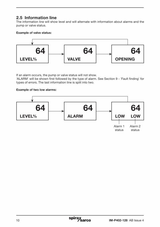
If an alarm occurs, the pump or valve status will not show.'ALARM' will be shown first followed by the type of alarm. See Section 9 - 'Fault finding' for types of errors. The last information line is split into two.
Example of two low alarms:
64ALARM
64LOW LOW
64LEVEL%
ä
ä ä
Alarm 1 status
Alarm 2 status
2.5 Information lineThe information line will show level and will alternate with information about alarms and the pump or valve status.
Example of valve status:
IM-P402-128 AB Issue 4 11
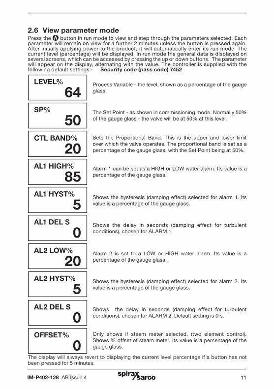
2.6 View parameter modePress the button in run mode to view and step through the parameters selected. Each parameter will remain on view for a further 2 minutes unless the button is pressed again.After initially applying power to the product, it will automatically enter its run mode. The current level (percentage) will be displayed. In run mode the general data is displayed on several screens, which can be accessed by pressing the up or down buttons. The parameter will appear on the display, alternating with the value. The controller is supplied with the following default settings:- Security code (pass code) 7452
LEVEL%
64SP%
50CTL BAND%
20AL1 HIGH%
85AL1 HYST%
5AL1 DEL S
0AL2 LOW%
20AL2 HYST%
5AL2 DEL S
0OFFSET%
0The display will always revert to displaying the current level percentage if a button has not been pressed for 5 minutes.
Process Variable - the level, shown as a percentage of the gauge glass.
The Set Point - as shown in commissioning mode. Normally 50% of the gauge glass - the valve will be at 50% at this level.
Sets the Proportional Band. This is the upper and lower limit over which the valve operates. The proportional band is set as a percentage of the gauge glass, with the Set Point being at 50%.
Alarm 1 can be set as a HIGH or LOW water alarm. Its value is a percentage of the gauge glass.
Shows the hysteresis (damping effect) selected for alarm 1. Its value is a percentage of the gauge glass.
Shows the delay in seconds (damping effect for turbulent conditions), chosen for ALARM 1.
Alarm 2 is set to a LOW or HIGH water alarm. Its value is a percentage of the gauge glass.
Shows the hysteresis (damping effect) selected for alarm 2. Its value is a percentage of the gauge glass.
Shows the delay in seconds (damping effect for turbulent conditions), chosen for ALARM 2. Default setting is 0 s.
Only shows if steam meter selected, (two element control). Shows % offset of steam meter. Its value is a percentage of the gauge glass.
IM-P402-128 AB Issue 412
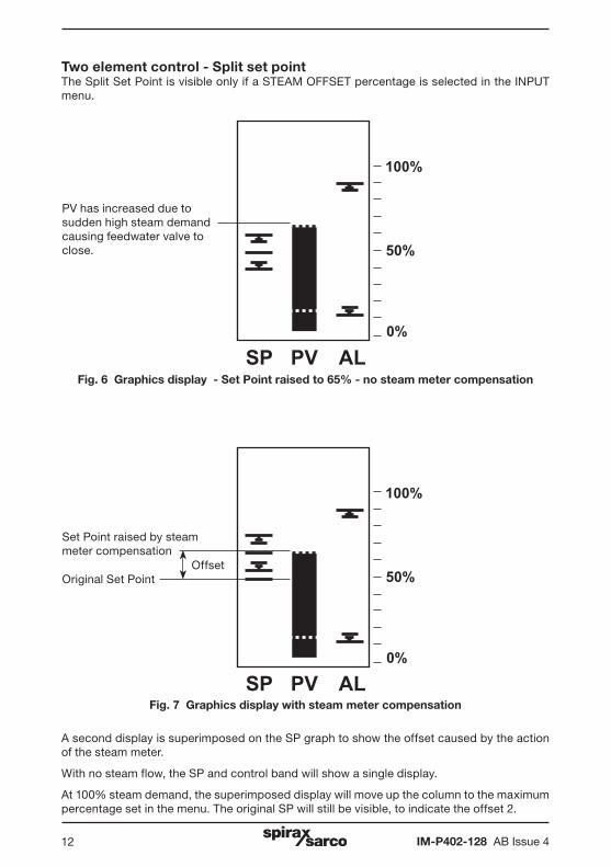
Two element control - Split set pointThe Split Set Point is visible only if a STEAM OFFSET percentage is selected in the INPUT menu.
Fig. 6 Graphics display - Set Point raised to 65% - no steam meter compensation
Fig. 7 Graphics display with steam meter compensation
100%
50%
0%
SP PV AL
100%
50%
0%
SP PV AL
A second display is superimposed on the SP graph to show the offset caused by the action of the steam meter.
With no steam flow, the SP and control band will show a single display.
At 100% steam demand, the superimposed display will move up the column to the maximum percentage set in the menu. The original SP will still be visible, to indicate the offset 2.
PV has increased due to sudden high steam demand causing feedwater valve to close.
Set Point raised by steam meter compensation
Original Set PointOffset
IM-P402-128 AB Issue 4 13
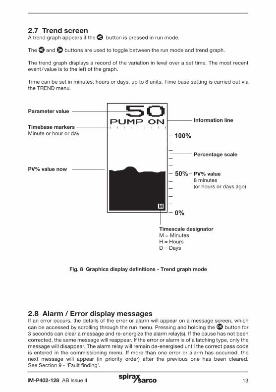
2.7 Trend screenA trend graph appears if the button is pressed in run mode.
The and buttons are used to toggle between the run mode and trend graph.
The trend graph displays a record of the variation in level over a set time. The most recent event / value is to the left of the graph.
Time can be set in minutes, hours or days, up to 8 units. Time base setting is carried out via the TREND menu.
100%
50%
0%M
Parameter value
Information line
Percentage scale
Timescale designatorM = MinutesH = HoursD = Days
Timebase markersMinute or hour or day
PV% value nowPV% value 8 minutes (or hours or days ago)
Fig. 8 Graphics display definitions - Trend graph mode
2.8 Alarm / Error display messagesIf an error occurs, the details of the error or alarm will appear on a message screen, which can be accessed by scrolling through the run menu. Pressing and holding the OK button for 3 seconds can clear a message and re-energize the alarm relay(s). If the cause has not been corrected, the same message will reappear. If the error or alarm is of a latching type, only the message will disappear. The alarm relay will remain de-energised until the correct pass code is entered in the commissioning menu. If more than one error or alarm has occurred, the next message will appear (in priority order) after the previous one has been cleared.See Section 9 - 'Fault finding'.
IM-P402-128 AB Issue 414
2.9 Equipment delivery, handling and storage
Factory shipmentPrior to shipment, the product is tested, calibrated and inspected to ensure proper operation.
Receipt of shipment.Each carton should be inspected at the time of delivery for possible external damage. Any visible damage should be recorded immediately on the carrier’s copy of the delivery slip.
Each carton should be unpacked carefully and its contents checked for damage. If it is found that some items have been damaged or are missing, notify Spirax Sarco immediately and provide full details. In addition, damage must be reported to the carrier with a request for their on-site inspection of the damaged item and its shipping carton.
StorageIf the product is to be stored for a period prior to installation, the environmental storage conditions should be at a temperature between 0°C and 65°C (32°F and 149°F), and between 10% and 90% relative humidity (non-condensing).
Before installing and connecting the power ensure there is no condensation within the unit.

IM-P402-128 AB Issue 4 15
3.1 FunctionThe product compares the input signals with the Set Point to control the water level in the boiler tank, or vessel, by operating a pump, valve, or solenoid.
On/off control- Pump control.
- Two alarm outputs.
- 4 - 20 mA level output (isolated).
Note: A solenoid valve may be used instead of a pump.
Modulating controlModulating valve control using valve motor drive (VMD) or 4 - 20 mA control signals:
- Two alarm outputs.
- 4 - 20 mA level output (isolated).
Two or three element modulating controlModulating valve control using valve motor drive or 4 - 20 mA control signals:
- Two alarm outputs.
- 4 - 20 mA level output (isolated).
- Feedback from steam meter.
- Feed forward from water meter.
3.2 InputsThe product has three inputs to accept the following signals:
- Level probe or transmitter 1-6 V or 4-20 mA outputs. Note: The level probe must be long enough to sense over the complete level range.
- Steam meter 4-20 mA output to compensate for the rise in water level due to increased steam demand (Two element control).
- A signal from a water meter to compensate for variations in feedwater flow rate (Three element control).
3.3 OutputsThe product control signal can be configured / wired to work with a pump or a modulating control valve. It also provides relay outputs for high and low level alarms and can provide an isolated 0-20 mA or 4-20 mA retransmission output.
Parameters can be remotely accessed via the RS485 / MODBUS communications.
3.4 Other featuresAn additional filter can be selected to increase the damping effect for turbulent conditions.
A test function provides the operator with a diagnostic feature. Inputs can be measured and outputs can be set from the front panel.
To prevent unwanted or inadvertent changes being made, all commissioning parameters are protected with a pass code. The operator can change this.
The LC2650 can communicate via an infra-red link between adjacent controllers - see Section 7 - 'Communications'.
3. System overview
IM-P402-128 AB Issue 416
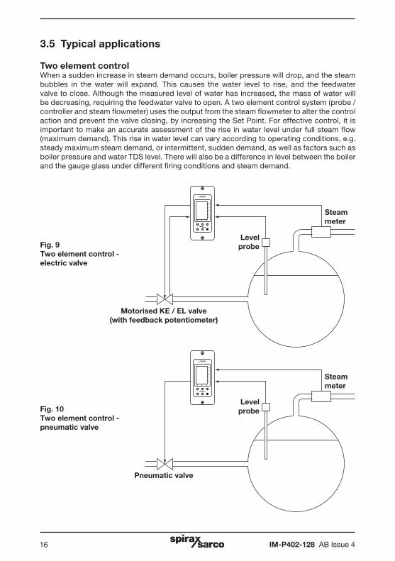
3.5 Typical applications
Two element controlWhen a sudden increase in steam demand occurs, boiler pressure will drop, and the steam bubbles in the water will expand. This causes the water level to rise, and the feedwater valve to close. Although the measured level of water has increased, the mass of water will be decreasing, requiring the feedwater valve to open. A two element control system (probe / controller and steam flowmeter) uses the output from the steam flowmeter to alter the control action and prevent the valve closing, by increasing the Set Point. For effective control, it is important to make an accurate assessment of the rise in water level under full steam flow (maximum demand). This rise in water level can vary according to operating conditions, e.g. steady maximum steam demand, or intermittent, sudden demand, as well as factors such as boiler pressure and water TDS level. There will also be a difference in level between the boiler and the gauge glass under different firing conditions and steam demand.
Fig. 9 Two element control - electric valve
Fig. 10 Two element control - pneumatic valve
OK
LC2650
100
50
0%
SP PV AL
OK
LC2650
100
50
0%
SP PV AL
Steam meter
Level probe
Motorised KE / EL valve (with feedback potentiometer)
Steam meter
Level probe
Pneumatic valve
IM-P402-128 AB Issue 4 17
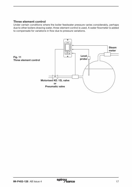
Three element controlUnder certain conditions where the boiler feedwater pressure varies considerably, perhaps due to other boilers drawing water, three-element control is used. A water flowmeter is added to compensate for variations in flow due to pressure variations.
Fig. 11 Three element control
OK
LC2650
100
50
0%
SP PV AL
Steam meter
Level probe
Motorised KE / EL valveor
Pneumatic valve
IM-P402-128 AB Issue 418
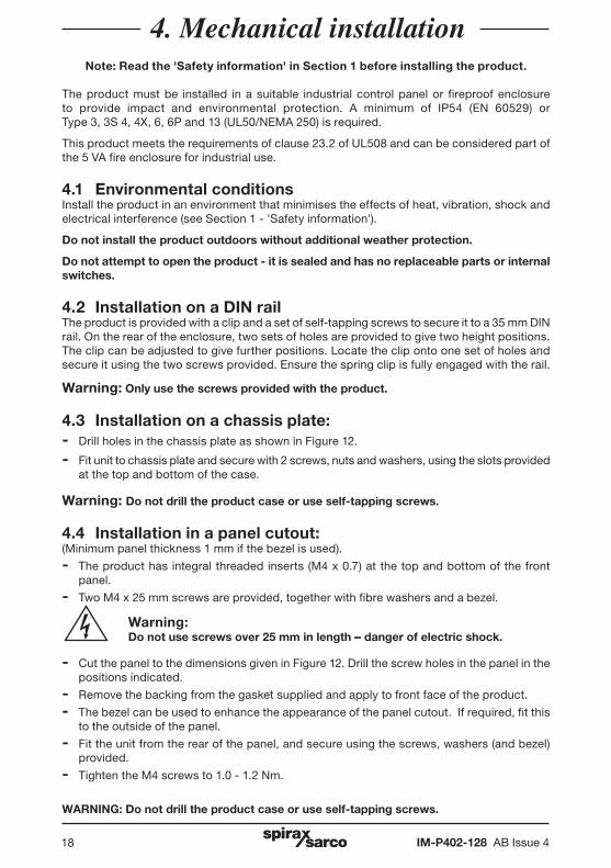
Note: Read the 'Safety information' in Section 1 before installing the product.
The product must be installed in a suitable industrial control panel or fireproof enclosure to provide impact and environmental protection. A minimum of IP54 (EN 60529) or Type 3, 3S 4, 4X, 6, 6P and 13 (UL50/NEMA 250) is required.
This product meets the requirements of clause 23.2 of UL508 and can be considered part of the 5 VA fire enclosure for industrial use.
4.1 Environmental conditionsInstall the product in an environment that minimises the effects of heat, vibration, shock and electrical interference (see Section 1 - 'Safety information').
Do not install the product outdoors without additional weather protection.
Do not attempt to open the product - it is sealed and has no replaceable parts or internal switches.
4.2 Installation on a DIN railThe product is provided with a clip and a set of self-tapping screws to secure it to a 35 mm DIN rail. On the rear of the enclosure, two sets of holes are provided to give two height positions. The clip can be adjusted to give further positions. Locate the clip onto one set of holes and secure it using the two screws provided. Ensure the spring clip is fully engaged with the rail.
Warning: Only use the screws provided with the product.
4.3 Installation on a chassis plate: - Drill holes in the chassis plate as shown in Figure 12.
- Fit unit to chassis plate and secure with 2 screws, nuts and washers, using the slots provided at the top and bottom of the case.
Warning: Do not drill the product case or use self-tapping screws.
4.4 Installation in a panel cutout: (Minimum panel thickness 1 mm if the bezel is used).
- The product has integral threaded inserts (M4 x 0.7) at the top and bottom of the front panel.
- Two M4 x 25 mm screws are provided, together with fibre washers and a bezel.
Warning: Do not use screws over 25 mm in length - danger of electric shock.
- Cut the panel to the dimensions given in Figure 12. Drill the screw holes in the panel in the positions indicated.
- Remove the backing from the gasket supplied and apply to front face of the product.
- The bezel can be used to enhance the appearance of the panel cutout. If required, fit this to the outside of the panel.
- Fit the unit from the rear of the panel, and secure using the screws, washers (and bezel) provided.
- Tighten the M4 screws to 1.0 - 1.2 Nm.
WARNING: Do not drill the product case or use self-tapping screws.
4. Mechanical installation
IM-P402-128 AB Issue 4 19
112 mm
67 mm
10 mm
45 mm
92 mm
22 mm
10 mm
22.5 mm
Ø 4.2 mm
Ø 4.2 mm
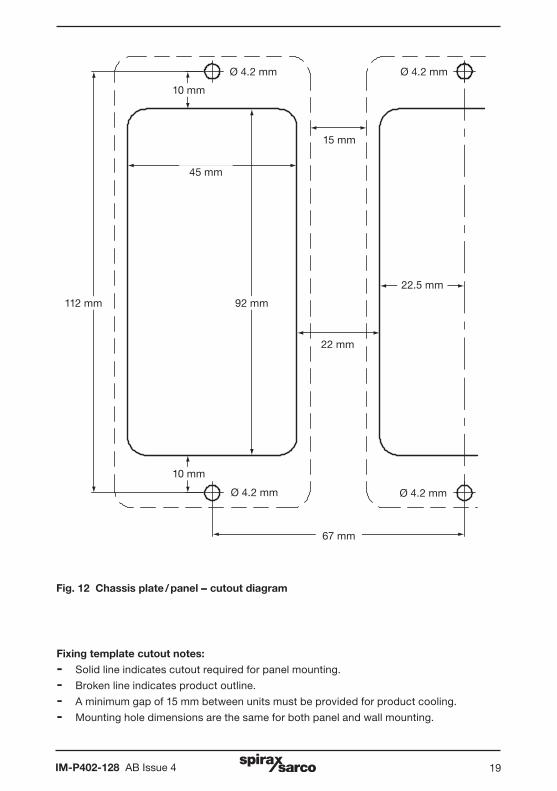
Fig. 12 Chassis plate / panel - cutout diagram
15 mm
Ø 4.2 mm
Ø 4.2 mm
Fixing template cutout notes:
- Solid line indicates cutout required for panel mounting.
- Broken line indicates product outline.
- A minimum gap of 15 mm between units must be provided for product cooling.
- Mounting hole dimensions are the same for both panel and wall mounting.
IM-P402-128 AB Issue 420
Note: Before installing read the ‘Safety Information’ in Section 1.
Warning:Isolate the mains supply before touching any of the wiring terminals as these may be wired to hazardous voltages.Use only the connectors supplied with the product, or spares obtained from Spirax Sarco Limited. Use of different connectors may compromise product safety and approvals. Ensure there is no condensation within the unit before installing and connecting the power.
Caution: Do not cover or obstruct the infrared beam between products.
5.1 General wiring notesEvery effort has been made during the design of the product to ensure the safety of the user but the following precautions must be observed:
1. Maintenance personnel must be suitably qualified to work with equipment having hazardous live voltages.
2. Ensure correct installation. Safety may be compromised if the installation of the product is not carried out as specified in this IMI.
3. The design of the product relies on the building installation for overcurrent protection and primary isolation.
4. Overcurrent protection devices rated at 3 amps must be included in all phase conductors of the installation wiring. If overcurrent protection is included in both supply wires then the operation of one must also cause the operation of the other. Refer to IEC 60364 (Electrical Installations of Buildings) or National or Local standards for full details of requirements for overcurrent protection.
5. A 3 A quick-blow overcurrent protection device must be fitted to the relay circuit(s).
6. Relay contacts must be supplied on the same phase as the mains supply.
7. The product is designed as an installation category III product.
8. Install wiring in accordance with:
- IEC 60364 - Low-voltage electrical installations.
- EN 50156 Electrical Equipment for furnaces and ancillary equipment.
- BS 6739 - Instrumentation in Process Control Systems: Installation design and practice or local equivalent.
- National and Local Electrical Code (NEC) or Canadian Electrical code (CEC) for the US and Canadian markets. Note; use NEC Class 1 wire with a temperature rating greater than 75°C. If the cable is to be exposed to a higher temperature, then a higher temperature rating needs to be selected.
5. Electrical installation
IM-P402-128 AB Issue 4 21
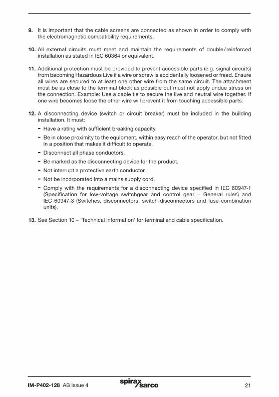
9. It is important that the cable screens are connected as shown in order to comply with the electromagnetic compatibility requirements.
10. All external circuits must meet and maintain the requirements of double / reinforced installation as stated in IEC 60364 or equivalent.
11. Additional protection must be provided to prevent accessible parts (e.g. signal circuits) from becoming Hazardous Live if a wire or screw is accidentally loosened or freed. Ensure all wires are secured to at least one other wire from the same circuit. The attachment must be as close to the terminal block as possible but must not apply undue stress on the connection. Example: Use a cable tie to secure the live and neutral wire together. If one wire becomes loose the other wire will prevent it from touching accessible parts.
12. A disconnecting device (switch or circuit breaker) must be included in the building installation. It must:
- Have a rating with sufficient breaking capacity.
- Be in close proximity to the equipment, within easy reach of the operator, but not fitted in a position that makes it difficult to operate.
- Disconnect all phase conductors.
- Be marked as the disconnecting device for the product.
- Not interrupt a protective earth conductor.
- Not be incorporated into a mains supply cord.
- Comply with the requirements for a disconnecting device specified in IEC 60947-1 (Specification for low-voltage switchgear and control gear - General rules) and
IEC 60947-3 (Switches, disconnectors, switch-disconnectors and fuse-combination units).
13. See Section 10 - 'Technical information' for terminal and cable specification.
IM-P402-128 AB Issue 422
Disconnect device conforming to IEC 60947-1 and IEC 60947-3
1
2
1
2
L
N
L1
L2
3 A fuseProduct
Product
230 / 115 Vacfrom supply
230 / 115 Vacfrom supply
3 A fuses
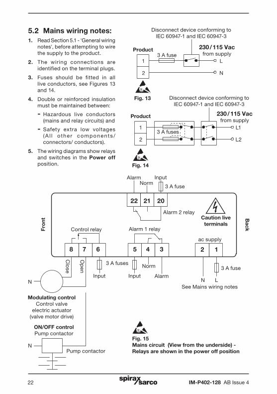
Fig. 15 Mains circuit (View from the underside) - Relays are shown in the power off position
Caution live terminals
ac supply
Control relay Alarm 1 relay
BackFr
ont
3 A fuses
Alarm
N LSee Mains wiring notes
InputNorm
2 1
3 A fuse
N
ON/OFF controlPump contactor
Modulating controlControl valve
electric actuator (valve motor drive)
Pump contactor
N
5 4 38 7 6
22 21 20
AlarmInput
Norm
Input
Op
en
Clo
seAlarm 2 relay
Fig. 13
Fig. 14
3 A fuse
Disconnect device conforming to IEC 60947-1 and IEC 60947-3
5.2 Mains wiring notes:1. Read Section 5.1 - 'General wiring
notes', before attempting to wire the supply to the product.
2. The wiring connections are identified on the terminal plugs.
3. Fuses should be fitted in all live conductors, see Figures 13 and 14.
4. Double or reinforced insulation must be maintained between:
- Hazardous live conductors (mains and relay circuits) and
- Safety extra low voltages (A l l o the r components / connectors/ conductors).
5. The wiring diagrams show relays and switches in the Power off position.

IM-P402-128 AB Issue 4 23
+-
+ -
++ - -Rin lin COM SCN
5.3 Signal wiring notesAn earth current loop is created if a wire or screen is connected between two earth points that are at different potential (voltage). If the wiring diagram is followed correctly, the screen will only be connected to the earth at one end.
The earth terminal is a functional earth rather than a protective earth.
A protective earth provides protection from electric shock under a single fault condition. This product has double insulation and therefore does not require a protective earth. A functional earth is used in order for the product to operate. In this application, the earth is used as a sink or drain for any electrical interference. The earth terminal must be connected to a local earth in order to conform to the EMC directive.
Bac
k Front
Notes:E = Functional earth - Connect these pins to a clean earth local to the panel
Connect to a clean earth local in the
panel
Fig. 16 Signal circuit (view from the top)
50 51 52 53
70 71 72 73 74
4-20 mA output
4-20 mAvalve positioner
4-20 mAwater
flowmeter
1 kohm feedback
potentiometervalve motor drive
Capacitance probe (see PA20 IMI for
sensitivity selection)
1 2
54 55 56 57 58 59 60 61 62
Feedback potentiometer / water meter
+24V Vin lin COM SCN E
Level input (s)
75 76 77 78 90 91 92 93 94 95 96 97 984-20 mA output
4-20 mA input
See RS485 / MODBUS wiring notes
Screens
4-20 mA steam meter
0-20 mA or4-20 mA output display
(0-100%)
Screens
Op
enC
lose
Connect to a clean earth local to the
panel
IM-P402-128 AB Issue 424
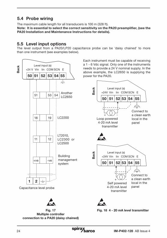
5.4 Probe wiringThe maximum cable length for all transducers is 100 m (328 ft).Note: It is essential to select the correct sensitivity on the PA20 preamplifier, (see the PA20 Installation and Maintenance Instructions for details).
5.5 Level input optionsThe level output from a PA20/LP20 capacitance probe can be 'daisy chained' to more than one instrument (see examples below).
Each instrument must be capable of receiving a 1 - 6 Vdc signal. Only one of the instruments needs to provide a 24 V nominal supply. In the above example, the LC2650 is supplying the power for the PA20.
Fig. 17 Multiple controller
connection to a PA20 (daisy chained)
Bac
k
50 51 52 53 54 55
51 53 54
18 19
11 12
+ve -ve
Another LC2650
LC2200
LT2010, LC2300 or LC2500
Building management system
+24 V Vin lin COM SCNLevel input (s)
1 2
50 51 52 53 54
+24V Vin lin COM SCNLevel input (s)
Connect to a clean earth local in the panel
Fig. 18 4 - 20 mA level transmitter
+ -Loop powered4-20 mA level
transmitter
+ -Self powered4-20 mA level
transmitter
Connect to a clean earth local in the panel
55
EBac
kB
ack
50 51 52 53 54
+24V Vin lin COM SCNLevel input (s)
55
E
E
Capacitance level probe
IM-P402-128 AB Issue 4 25
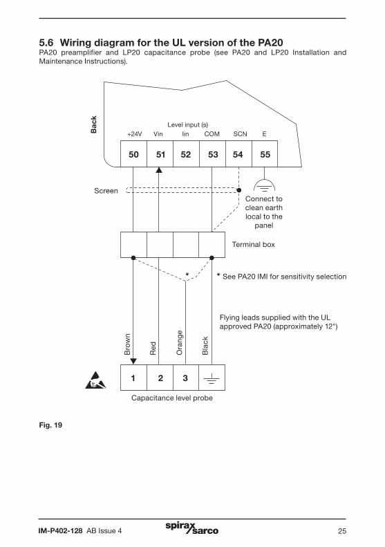
5.6 Wiring diagram for the UL version of the PA20PA20 preamplifier and LP20 capacitance probe (see PA20 and LP20 Installation and Maintenance Instructions).
Fig. 19
Capacitance level probe
Bac
k
50
+24V Vin lin COM SCNLevel input (s)
51 52 53 54 55
E
Connect to clean earth local to the
panel
Screen
Terminal box
Bro
wn
Red
Ora
nge
Bla
ck
1 2 3
* * See PA20 IMI for sensitivity selection
Flying leads supplied with the UL approved PA20 (approximately 12")
IM-P402-128 AB Issue 426
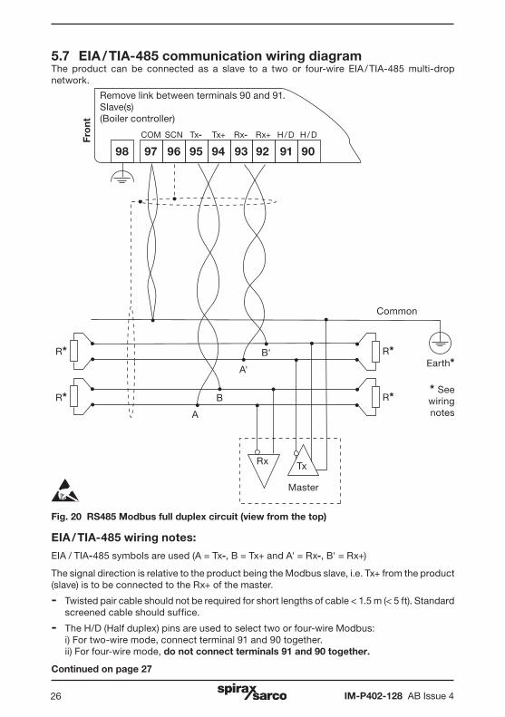
5.7 EIA / TIA-485 communication wiring diagramThe product can be connected as a slave to a two or four-wire EIA / TIA-485 multi-drop network.
EIA / TIA-485 wiring notes:
EIA / TIA-485 symbols are used (A = Tx-, B = Tx+ and A' = Rx-, B' = Rx+)
The signal direction is relative to the product being the Modbus slave, i.e. Tx+ from the product (slave) is to be connected to the Rx+ of the master.
- Twisted pair cable should not be required for short lengths of cable < 1.5 m (< 5 ft). Standard screened cable should suffice.
- The H/D (Half duplex) pins are used to select two or four-wire Modbus: i) For two-wire mode, connect terminal 91 and 90 together. ii) For four-wire mode, do not connect terminals 91 and 90 together. Continued on page 27
A
B
A'
B'
Rx Tx
Master
Common
Earth*
R* R** See wiring notes
Fro
ntRemove link between terminals 90 and 91. Slave(s) (Boiler controller)
909192939495969798
H / DH / DRx+Rx-Tx+Tx-SCNCOM
R* R*
Fig. 20 RS485 Modbus full duplex circuit (view from the top)
IM-P402-128 AB Issue 4 27
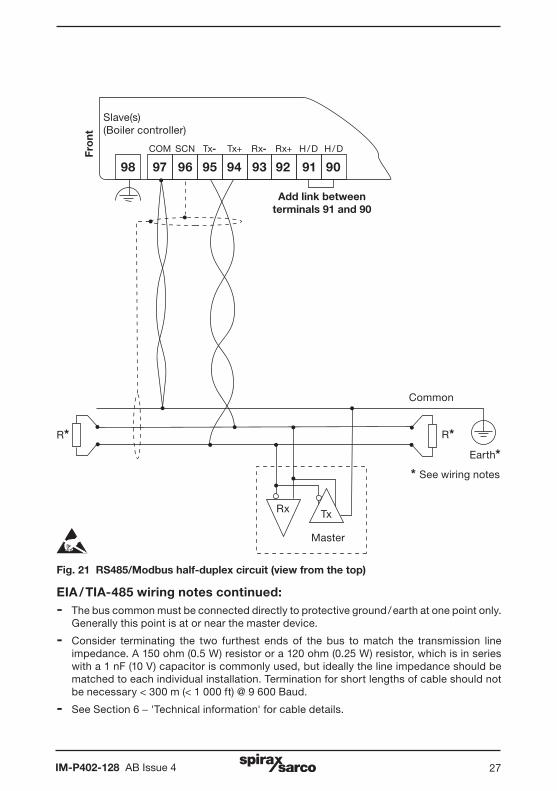
EIA / TIA-485 wiring notes continued:- The bus common must be connected directly to protective ground / earth at one point only.
Generally this point is at or near the master device.
- Consider terminating the two furthest ends of the bus to match the transmission line impedance. A 150 ohm (0.5 W) resistor or a 120 ohm (0.25 W) resistor, which is in series with a 1 nF (10 V) capacitor is commonly used, but ideally the line impedance should be matched to each individual installation. Termination for short lengths of cable should not be necessary < 300 m (< 1 000 ft) @ 9 600 Baud.
- See Section 6 - 'Technical information' for cable details.
Rx Tx
Master
Common
Earth*
R* R*
* See wiring notes
Fro
nt
Slave(s)(Boiler controller)
909192939495969798
H / DH / DRx+Rx-Tx+Tx-SCNCOM
Add link between terminals 91 and 90
Fig. 21 RS485/Modbus half-duplex circuit (view from the top)
IM-P402-128 AB Issue 428
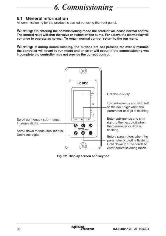
6. Commissioning6.1 General informationAll commissioning for the product is carried out using the front panel.
Warning: On entering the commissioning mode the product will cease normal control. The control relay will shut the valve or switch off the pump. For safety, the alarm relay will continue to operate as normal. To regain normal control, return to the run menu.
Warning: If during commissioning, the buttons are not pressed for over 5 minutes, the controller will revert to run mode and an error will occur. If the commissioning was incomplete the controller may not provide the correct control.
Fig. 22 Display screen and keypad
OK
LC2650
100
50
0%
SP PV AL
Scroll down menus /sub-menus. Decrease digits.
Scroll up menus / sub-menus. Increase digits.
Enter sub-menus and shift right to the next digit when the parameter or digit is flashing.
Enters parameters when the parameter or digit is flashing. Hold down for 5 seconds to enter commissioning mode.
Exit sub-menus and shift left to the next digit when the parameter or digit is flashing.
Graphic display
IM-P402-128 AB Issue 4 29
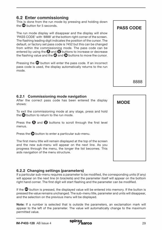
6.2 Enter commissioning This is done from the run mode by pressing and holding down the OK button for 5 seconds.
The run mode display will disappear and the display will show 'PASS CODE' with '8888' at the bottom right corner of the screen. The flashing leading digit indicates the position of the cursor. The default, or factory set pass code is 7452 but this can be changed from within the commissioning mode. The pass code can be entered by using the and buttons to increase or decrease the flashing value and the and buttons to move the cursor.
Pressing the OK button will enter the pass code. If an incorrect pass code is used, the display automatically returns to the run mode.
6.2.1 Commissioning mode navigationAfter the correct pass code has been entered the display shows:
To exit the commissioning mode at any stage, press and hold the button to return to the run mode.
Press the and buttons to scroll through the first level menus.
Press the button to enter a particular sub-menu.
The first menu title will remain displayed at the top of the screen and the new sub-menu will appear on the next line. As you progress through the menu, the longer the list becomes. This aids navigation of the menu structure.
MODE
PASS CODE
8888
6.2.2 Changing settings (parameters)If a particular sub-menu requires a parameter to be modified, the corresponding units (if any) will appear on the next line (in brackets) and the parameter itself will appear on the bottom right hand corner. The first digit will start flashing and the parameter can be modified.
If the OK button is pressed, the displayed value will be entered into memory. If the button is pressed the value remains unchanged. The sub-menu title, parameter and units will disappear, and the selection on the previous menu will be displayed.
Note: If a number is selected that is outside the parameters, an exclamation mark will appear to the left of the parameter. The value will automatically change to the maximum permitted value.
IM-P402-128 AB Issue 430
6.3 Commissioning - Quick set-up This section allows the user to carry out the minimum commissioning necessary to operate the system.
It accepts the defaults set in the factory, so will only work if the original default settings have not been altered - see Technical Information to confirm.
Settings can then be tailored to suit the individual requirements of the customer / application if required.
WarningIt is essential that you comply with National / Local regulations and Guidance notes, and the boiler manufacturers' recommendations. It is imperative that the settings you have accepted will allow the boiler to operate in a safe manner.
Calibration water level:- Lower the water level to the lowest point required (water must still be visible in the gauge glass for boiler applications) and ENTER INPUT LEVEL CAL MIN.
- Raise the water level to the highest point required, and ENTER INPUT LEVEL CAL MAX.
Note: When in the INPUT-LEVEL-CAL menu, the display will show the voltage or current being output by the level transducer.
ON/OFF control (pumping-in) using an LP20/PA20.From the menu select:
OUTPUTS DRIVE CONTROL ON-OFF
Modulating control (pumping in) using an LP20 / PA20 and EL5600 series actuator.
OUTPUTS DRIVE CONTROL PROP
Calibration feedback potentiometer on the EL5600:
Select INPUT POT CAL MIN.
- The valve will automatically close. When fully closed (voltage will stop decreasing), press OK .
Select INPUT POT CAL MAX.
- The valve will automatically open. When fully open (voltage will stop increasing), press OK .
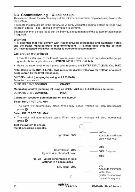
Test the system to ensure that it is working correctly.
Fig. 23 Typical percentages of level settings in a gauge glass
100%Absolute maximum safe water level
60%
40%
50% Set point
0%Absolute minimum water level(water must always be visible in glass)
High alarm 85%
Low alarm 20%
Control band 20%(symmetrical about set point)
IM-P402-128 AB Issue 4 31
60%
40%
50% Set point
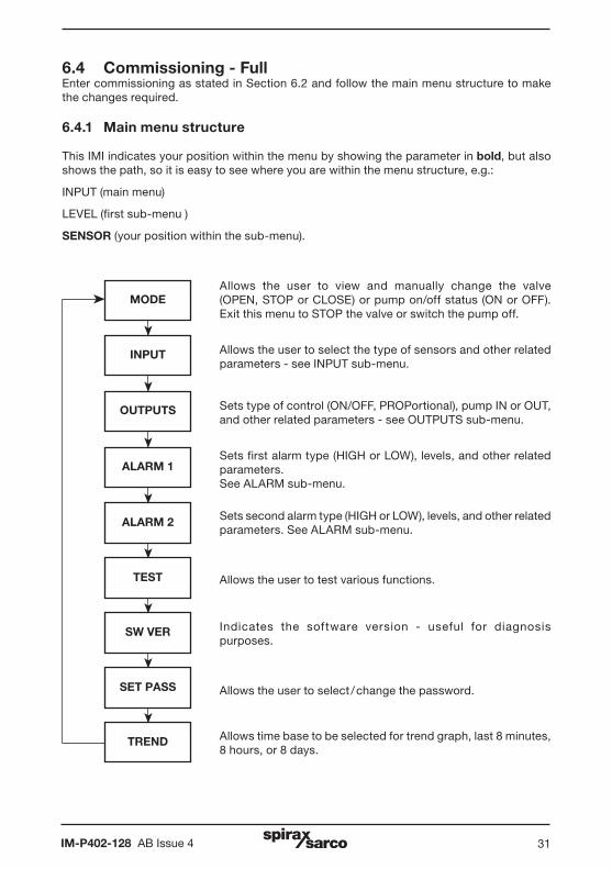
6.4 Commissioning - FullEnter commissioning as stated in Section 6.2 and follow the main menu structure to make the changes required.
6.4.1 Main menu structure
This IMI indicates your position within the menu by showing the parameter in bold, but also shows the path, so it is easy to see where you are within the menu structure, e.g.:
INPUT (main menu)
LEVEL (first sub-menu )
SENSOR (your position within the sub-menu).
MODEä
ä
OUTPUTS
ALARM 1
ALARM 2
TEST
SW VER
SET PASS
TREND
INPUT
ää
ää
ää
ä
Allows the user to view and manually change the valve (OPEN, STOP or CLOSE) or pump on/off status (ON or OFF). Exit this menu to STOP the valve or switch the pump off.
Allows the user to select the type of sensors and other related parameters - see INPUT sub-menu.
Sets type of control (ON/OFF, PROPortional), pump IN or OUT, and other related parameters - see OUTPUTS sub-menu.
Sets first alarm type (HIGH or LOW), levels, and other related parameters. See ALARM sub-menu.
Sets second alarm type (HIGH or LOW), levels, and other related parameters. See ALARM sub-menu.
Allows the user to test various functions.
Indicates the software version - useful for diagnosis purposes.
Allows the user to select / change the password.
Allows time base to be selected for trend graph, last 8 minutes, 8 hours, or 8 days.
IM-P402-128 AB Issue 432
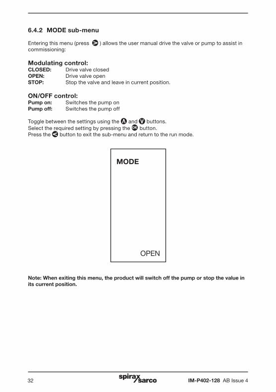
6.4.2 MODE sub-menu
Entering this menu (press ) allows the user manual drive the valve or pump to assist in commissioning:
Modulating control:CLOSED: Drive valve closedOPEN: Drive valve openSTOP: Stop the valve and leave in current position.
ON/OFF control:Pump on: Switches the pump onPump off: Switches the pump off
Toggle between the settings using the and buttons. Select the required setting by pressing the OK button. Press the button to exit the sub-menu and return to the run mode.
MODE
OPEN
Note: When exiting this menu, the product will switch off the pump or stop the value in its current position.
IM-P402-128 AB Issue 4 33
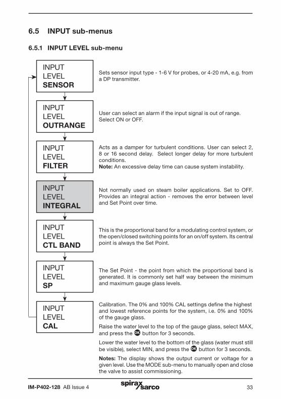
6.5 INPUT sub-menus
6.5.1 INPUT LEVEL sub-menu
ä
ä
ä
INPUTLEVELSENSOR
INPUTLEVELOUTRANGE
INPUTLEVELFILTER
ää
INPUTLEVELINTEGRAL
INPUTLEVELCTL BAND
ä
INPUTLEVELSP
Sets sensor input type - 1-6 V for probes, or 4-20 mA, e.g. from a DP transmitter.
User can select an alarm if the input signal is out of range. Select ON or OFF.
Acts as a damper for turbulent conditions. User can select 2, 8 or 16 second delay. Select longer delay for more turbulent conditions. Note: An excessive delay time can cause system instability.
Not normally used on steam boiler applications. Set to OFF. Provides an integral action - removes the error between level and Set Point over time.
This is the proportional band for a modulating control system, or the open/closed switching points for an on/off system. Its central point is always the Set Point.
The Set Point - the point from which the proportional band is generated. It is commonly set half way between the minimum and maximum gauge glass levels.
ä
INPUTLEVELCAL
Calibration. The 0% and 100% CAL settings define the highestand lowest reference points for the system, i.e. 0% and 100%of the gauge glass.
Raise the water level to the top of the gauge glass, select MAX, and press the OK button for 3 seconds.
Lower the water level to the bottom of the glass (water must still be visible), select MIN, and press the OK button for 3 seconds.
Notes: The display shows the output current or voltage for a given level. Use the MODE sub-menu to manually open and close the valve to assist commissioning.
IM-P402-128 AB Issue 434
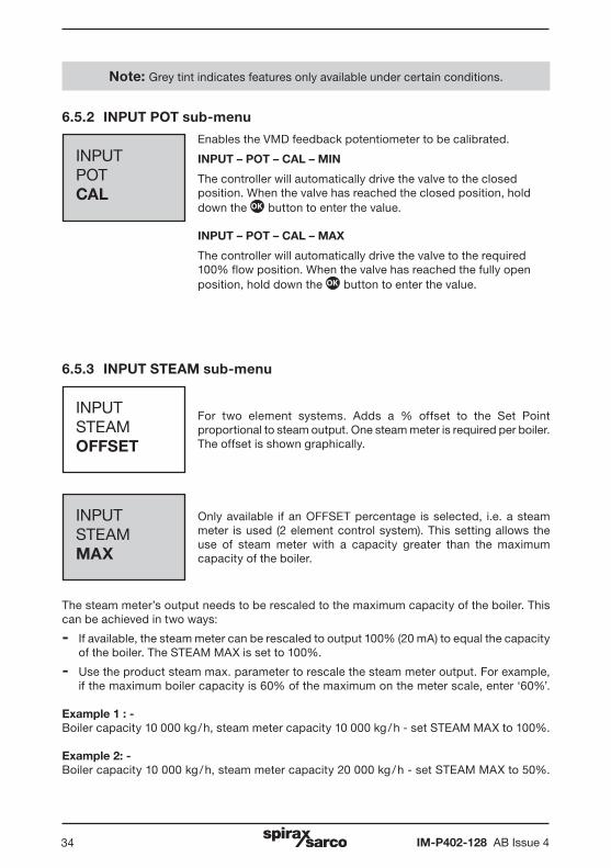
6.5.2 INPUT POT sub-menu
INPUTPOTCAL
Enables the VMD feedback potentiometer to be calibrated.
INPUT – POT – CAL – MIN
The controller will automatically drive the valve to the closed position. When the valve has reached the closed position, hold down the OK button to enter the value.
INPUT – POT – CAL – MAX
The controller will automatically drive the valve to the required 100% flow position. When the valve has reached the fully open position, hold down the OK button to enter the value.
6.5.3 INPUT STEAM sub-menu
INPUTSTEAMOFFSET
For two element systems. Adds a % offset to the Set Point proportional to steam output. One steam meter is required per boiler. The offset is shown graphically.
INPUTSTEAMMAX
Only available if an OFFSET percentage is selected, i.e. a steam meter is used (2 element control system). This setting allows the use of steam meter with a capacity greater than the maximum capacity of the boiler.
The steam meter’s output needs to be rescaled to the maximum capacity of the boiler. This can be achieved in two ways:
- If available, the steam meter can be rescaled to output 100% (20 mA) to equal the capacity of the boiler. The STEAM MAX is set to 100%.
- Use the product steam max. parameter to rescale the steam meter output. For example, if the maximum boiler capacity is 60% of the maximum on the meter scale, enter ‘60%’.
Example 1 : -Boiler capacity 10 000 kg / h, steam meter capacity 10 000 kg / h - set STEAM MAX to 100%.
Example 2: -Boiler capacity 10 000 kg / h, steam meter capacity 20 000 kg / h - set STEAM MAX to 50%.
Note: Grey tint indicates features only available under certain conditions.
IM-P402-128 AB Issue 4 35
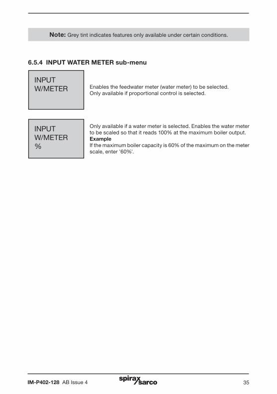
6.5.4 INPUT WATER METER sub-menu
INPUTW/METER Enables the feedwater meter (water meter) to be selected.
Only available if proportional control is selected.
INPUTW/METER%
Only available if a water meter is selected. Enables the water meter to be scaled so that it reads 100% at the maximum boiler output. ExampleIf the maximum boiler capacity is 60% of the maximum on the meter scale, enter '60%'.
Note: Grey tint indicates features only available under certain conditions.
IM-P402-128 AB Issue 436
ä
ä
ä
OUTPUTDRIVE
OUTPUTRETRANS
OUTPUTPOSITION
ä
OUTPUTCOMMS
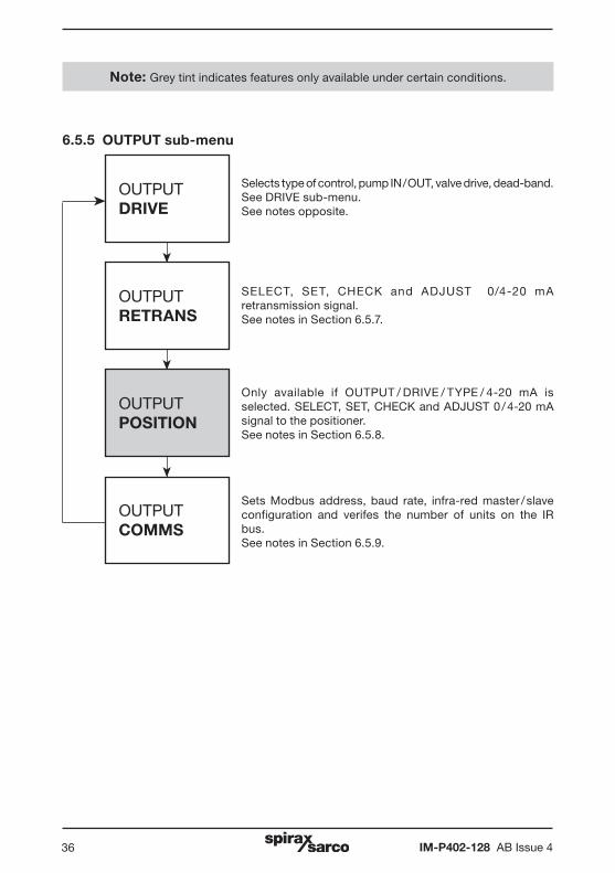
6.5.5 OUTPUT sub-menu
Selects type of control, pump IN / OUT, valve drive, dead-band.See DRIVE sub-menu. See notes opposite.
SELECT, SET, CHECK and ADJUST 0/4-20 mA retransmission signal. See notes in Section 6.5.7.
Only available if OUTPUT / DRIVE / TYPE / 4-20 mA is selected. SELECT, SET, CHECK and ADJUST 0 / 4-20 mA signal to the positioner.See notes in Section 6.5.8.
Sets Modbus address, baud rate, infra-red master / slave configuration and verifes the number of units on the IR bus.See notes in Section 6.5.9.
Note: Grey tint indicates features only available under certain conditions.

IM-P402-128 AB Issue 4 37
ä
ä
ä
OUTPUTDRIVECONTROL
OUTPUTDRIVEACTION
OUTPUTDRIVETYPE
ä
OUTPUTDRIVEDEADBAND
6.5.6 OUTPUT DRIVE sub-menu
Sets type of valve control - ON OFF or PROP (proportional).
Selects PUMP IN or PUMP OUT, i.e. fill or empty control.
Only available if proportional control is selected. Selects method of valve actuator operation - Valve Motor Drive (VMD), or 4-20 mA.
Only available if proportional control is selected. A wider DEADBAND is set for more turbulent water conditions. Set to 10% as a starting point.
Note: Grey tint indicates features only available under certain conditions.
IM-P402-128 AB Issue 438
6.5.7 OUTPUTS RETRANS
Enables the water level to be remotely sensed, recorded or displayed.
0 or 4 mAThis menu enables the user to choose between a 0 or 4 mA minimum setting. Default 4 mA. (4 mA is used so that a 0 mA signal will act as an indication of a fault).
SET4 mA and 20 mA retransmission levels are set as a percentage of the gauge glass, normally 4 mA = 0% and 20 mA = 100, though this can be changed if required. Setting a 4 mA to a percentage level higher tha the 20 mA setting will invert the transmitted. e.g. rising water level, with reducing current.
CHECKEnables the user to make adjustments to the 4 mA and 20 mA settings, to calibrate to a DVM reading, for example.
6.5.8 OUTPUTS POSITION
Outputs a signal to a 4-20 mA positioner.
0 or 4 mAThis menu enables the user to choose between a 0 or 4 mA minimum setting. Default 4 mA. (4 mA is used so that a 0 mA signal will act as an indication of a fault).
SETEnables the rescaling of the 4-20 mA signal to the positioner. Normally 4 mA = 0% and 20 mA = 100% of the required valve position. Setting 4 mA to 100% and 20 mA to 0% will invert the transmitted signal.
CHECKEnables the user to make adjustments to the 4 mA and 20 mA settings, to calibrate to a DVM reading, for example.
6.5.9 OUTPUTS COMMS
Address is set to 1 unless there are other units on the same system.
Baud rate - Set to match the Baud rate of the line or system.
IR COMMS - Infrared, select as a master or slave device. See Section 7 - 'Communications'.
IM-P402-128 AB Issue 4 39
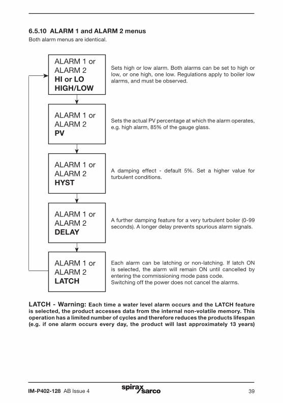
6.5.10 ALARM 1 and ALARM 2 menusBoth alarm menus are identical.
ä
ä
ä
ALARM 1 orALARM 2HI or LOHIGH/LOW
ALARM 1 orALARM 2PV
ALARM 1 orALARM 2HYST
ä
ALARM 1 orALARM 2DELAY
ä
ALARM 1 orALARM 2LATCH
Sets high or low alarm. Both alarms can be set to high or low, or one high, one low. Regulations apply to boiler low alarms, and must be observed.
Sets the actual PV percentage at which the alarm operates, e.g. high alarm, 85% of the gauge glass.
A damping effect - default 5%. Set a higher value for turbulent conditions.
A further damping feature for a very turbulent boiler (0-99 seconds). A longer delay prevents spurious alarm signals.
Each alarm can be latching or non-latching. If latch ON is selected, the alarm will remain ON until cancelled by entering the commissioning mode pass code.Switching off the power does not cancel the alarms.
LATCH - Warning: Each time a water level alarm occurs and the LATCH feature is selected, the product accesses data from the internal non-volatile memory. This operation has a limited number of cycles and therefore reduces the products lifespan (e.g. if one alarm occurs every day, the product will last approximately 13 years)

IM-P402-128 AB Issue 440
6.5.11 Test menuAllows access to the diagnostic features
ä
ä
ä
TESTDISPLAY
TESTINPUT
TESTOUTPUT
All display pixels will be activated - black background. Press down button to go to TEST INPUT. Press the left button to cancel the test and step to SW.VER.
Displays the input signal on each input. See TEST INPUT Sub-menu.
Sets the outputs to the required configuration. See TEST OUTPUT sub-menu.
IM-P402-128 AB Issue 4 41
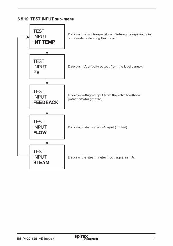
6.5.12 TEST INPUT sub-menu
ä
ä
ä
TESTINPUTINT TEMP
TESTINPUTPV
TESTINPUTFEEDBACK
ä
TESTINPUTFLOW
ä
TESTINPUTSTEAM
Displays current temperature of internal components in °C. Resets on leaving the menu.
Displays mA or Volts output from the level sensor.
Displays voltage output from the valve feedback potentiometer (if fitted).
Displays water meter mA input (if fitted).
Displays the steam meter input signal in mA.
IM-P402-128 AB Issue 442
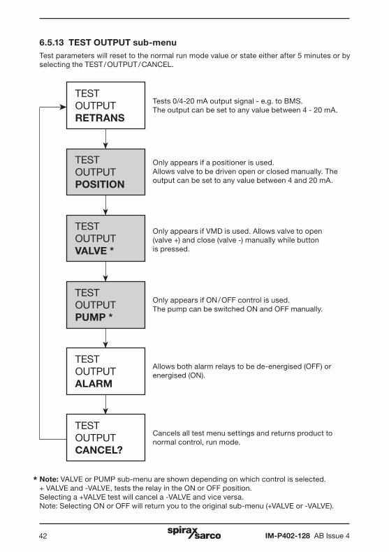
6.5.13 TEST OUTPUT sub-menuTest parameters will reset to the normal run mode value or state either after 5 minutes or by selecting the TEST / OUTPUT / CANCEL.
ä
ä
ä
TESTOUTPUTRETRANS
TESTOUTPUTPOSITION
TESTOUTPUTPUMP *
ä
TESTOUTPUTALARM
ä
TESTOUTPUTCANCEL?
Tests 0/4-20 mA output signal - e.g. to BMS.The output can be set to any value between 4 - 20 mA.
Only appears if a positioner is used.Allows valve to be driven open or closed manually. The output can be set to any value between 4 and 20 mA.
Only appears if ON / OFF control is used. The pump can be switched ON and OFF manually.
Allows both alarm relays to be de-energised (OFF) or energised (ON).
Cancels all test menu settings and returns product to normal control, run mode.
TESTOUTPUTVALVE *
Only appears if VMD is used. Allows valve to open (valve +) and close (valve -) manually while button is pressed.
ä
Note: VALVE or PUMP sub-menu are shown depending on which control is selected.+ VALVE and -VALVE, tests the relay in the ON or OFF position.Selecting a +VALVE test will cancel a -VALVE and vice versa.Note: Selecting ON or OFF will return you to the original sub-menu (+VALVE or -VALVE).
*

IM-P402-128 AB Issue 4 43
6.5.14 SOFTWARE VERSION sub-menu
SET PASS Allows the default pass code to be changed to a user-defined code. It is important that if the default pass code is changed that the new code is noted and kept safe.
6.5.15 PASS CODE sub-menu
SW VERAllows the software version to be viewed - useful for fault diagnosis.
IM-P402-128 AB Issue 444
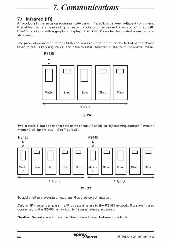
7. Communications7.1 Infrared (IR)All products in the range can communicate via an infrared bus between adjacent controllers. It enables the parameters of up to seven products to be passed to a product fitted with RS485 (products with a graphics display). The LC2650 can be designated a master or a slave unit.
The product connected to the RS485 networks must be fitted on the left of all the slaves fitted to the IR bus (Figure 24) and have ‘master’ selected in the ‘output-comms’ menu.
Master Slave
IR Bus
RS485
Fig. 24
Slave Slave Slave
Two or more IR buses can share the same enclosure or DIN rail by selecting another IR master. Master 2 will ignore bus 1. See Figure 25.
To add another slave into an existing IR bus, re-select ‘master’.
Only an IR master can pass the IR bus parameters to the RS485 network. If a slave is also connected to the RS485 network, only its parameters are passed.
Caution: Do not cover or obstruct the infrared beam between products.
Fig. 25
Master 1
IR Bus 1
RS485
IR Bus 2
RS485
Slave Slave Slave Slave Master 2
Slave Slave Slave Slave
IM-P402-128 AB Issue 4 45
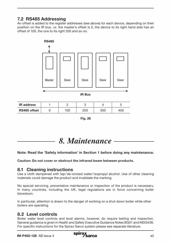
7.2 RS485 AddressingAn offset is added to the register addresses (see above) for each device, depending on their position on the IR bus, i.e. the master’s offset is 0, the device to its right hand side has an offset of 100, the one to its right 200 and so on.
Fig. 26
Master Slave
IR Bus
RS485
Slave Slave Slave
IR address 1 2 3 4 5
RS485 offset 0 100 200 300 400
8. MaintenanceNote: Read the 'Safety information' in Section 1 before doing any maintenance.
Caution: Do not cover or obstruct the infrared beam between products.
8.1 Cleaning instructionsUse a cloth dampened with tap / de-ionized water / isopropyl alcohol. Use of other cleaning materials could damage the product and invalidate the marking.
No special servicing, preventative maintenance or inspection of the product is necessary. In many countries, including the UK, legal regulations are in force concerning boiler blowdown.
In particular, attention is drawn to the danger of working on a shut-down boiler while otherboilers are operating.
8.2 Level controlsBoiler water level controls and level alarms, however, do require testing and inspection. General guidance is given in Health and Safety Executive Guidance Notes BG01 and INDG436. For specific instructions for the Spirax Sarco system please see separate literature.
IM-P402-128 AB Issue 446
9. Fault finding
WARNING:Before fault finding read the Safety information in Section 1 and the General wiring notes in Section 5.1.
Please note that there are hazardous voltages present and only suitably qualified personnel should carry out fault finding.
The product must be isolated from the mains supply before touching any of the terminals.
Safety may be compromised if the fault finding procedures are not carried out in line with this manual.
9.1 IntroductionThe most likely time for faults to occur is during installation and commissioning. The most common fault is incorrect wiring. If after applying power to the product an error message is displayed, it may be necessary to fault find. To simplify and aid in this process, the product has a Test menu (see Sections 2.8 and 6.4.1).
There are six viewable input channels. This will prove whether or not the product is functioning correctly.
9.2 System faults
Symptom Action
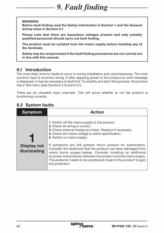
1Display not illuminating
1. Switch off the mains supply to the product.2. Check all wiring is correct.3. Check external fuse(s) are intact. Replace if necessary.4. Check the mains voltage is within specification.5. Switch on mains supply.
If symptoms are still present return product for examination. Consider the likelihood that the product has been damaged from mains borne surges / spikes. Consider installing an additional ac power line protector between the product and the mains supply. The protector needs to be positioned close to the product to gain full protection.
IM-P402-128 AB Issue 4 47
Symptom Action
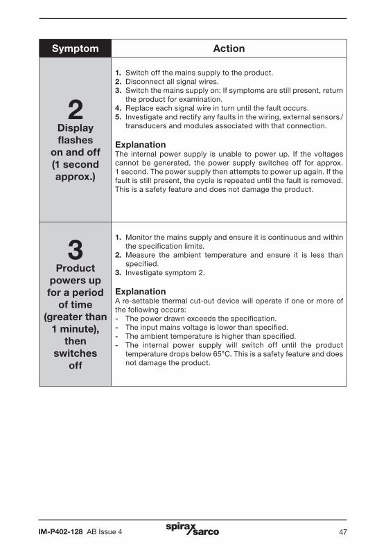
2Display flashes
on and off(1 second approx.)
1. Switch off the mains supply to the product.2. Disconnect all signal wires.3. Switch the mains supply on: If symptoms are still present, return
the product for examination.4. Replace each signal wire in turn until the fault occurs.5. Investigate and rectify any faults in the wiring, external sensors /
transducers and modules associated with that connection.
ExplanationThe internal power supply is unable to power up. If the voltages cannot be generated, the power supply switches off for approx.1 second. The power supply then attempts to power up again. If the fault is still present, the cycle is repeated until the fault is removed. This is a safety feature and does not damage the product.
3Product
powers up for a period
of time (greater than
1 minute), then
switches off
1. Monitor the mains supply and ensure it is continuous and within the specification limits.
2. Measure the ambient temperature and ensure it is less than specified.
3. Investigate symptom 2.
ExplanationA re-settable thermal cut-out device will operate if one or more of the following occurs:- The power drawn exceeds the specification.- The input mains voltage is lower than specified.- The ambient temperature is higher than specified. - The internal power supply will switch off until the product
temperature drops below 65°C. This is a safety feature and does not damage the product.
IM-P402-128 AB Issue 448
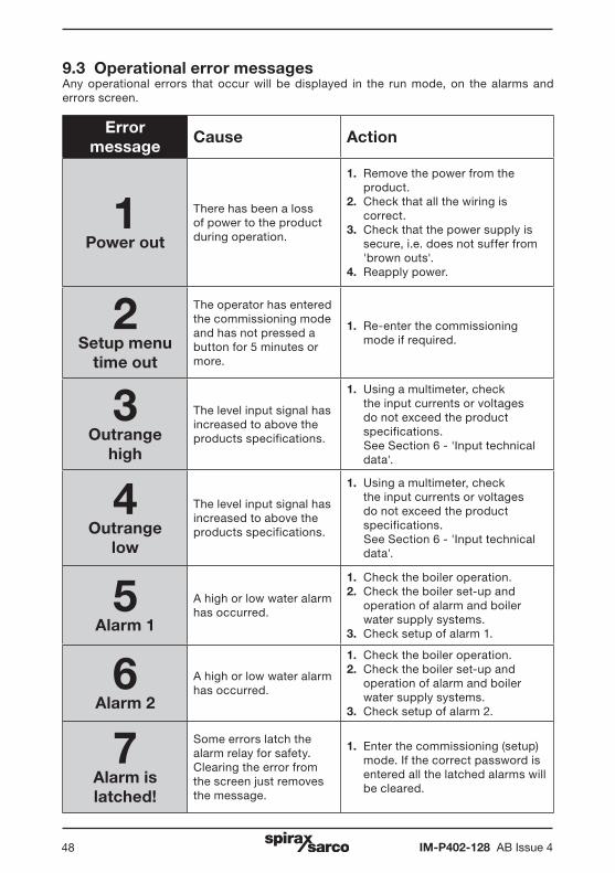
9.3 Operational error messagesAny operational errors that occur will be displayed in the run mode, on the alarms and errors screen.
Error message
Cause Action
1Power out
There has been a loss of power to the product during operation.
1. Remove the power from the product.
2. Check that all the wiring is correct.
3. Check that the power supply is secure, i.e. does not suffer from 'brown outs'.
4. Reapply power.
2Setup menu
time out
The operator has entered the commissioning mode and has not pressed a button for 5 minutes or more.
1. Re-enter the commissioning mode if required.
3Outrange
high
The level input signal has increased to above the products specifications.
1. Using a multimeter, check the input currents or voltages do not exceed the product specifications.
See Section 6 - 'Input technical data'.
4Outrange
low
The level input signal has increased to above the products specifications.
1. Using a multimeter, check the input currents or voltages do not exceed the product specifications.
See Section 6 - 'Input technical data'.
5Alarm 1
A high or low water alarm has occurred.
1. Check the boiler operation.2. Check the boiler set-up and
operation of alarm and boiler water supply systems.
3. Check setup of alarm 1.
6Alarm 2
A high or low water alarm has occurred.
1. Check the boiler operation.2. Check the boiler set-up and
operation of alarm and boiler water supply systems.
3. Check setup of alarm 2.
7Alarm is latched!
Some errors latch the alarm relay for safety. Clearing the error from the screen just removes the message.
1. Enter the commissioning (setup) mode. If the correct password is entered all the latched alarms will be cleared.
IM-P402-128 AB Issue 4 49
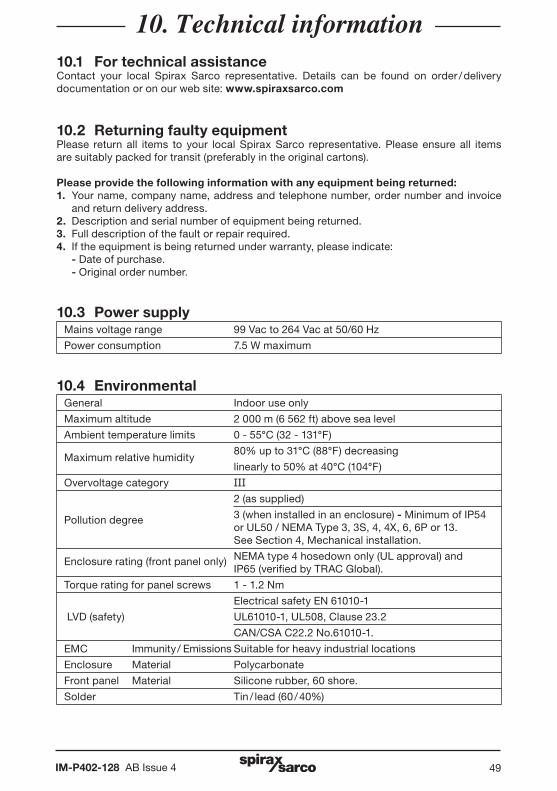
10. Technical information10.1 For technical assistanceContact your local Spirax Sarco representative. Details can be found on order / delivery documentation or on our web site: www.spiraxsarco.com
10.2 Returning faulty equipment Please return all items to your local Spirax Sarco representative. Please ensure all items are suitably packed for transit (preferably in the original cartons).
Please provide the following information with any equipment being returned:1. Your name, company name, address and telephone number, order number and invoice
and return delivery address.2. Description and serial number of equipment being returned.3. Full description of the fault or repair required.4. If the equipment is being returned under warranty, please indicate: - Date of purchase. - Original order number.
10.3 Power supply Mains voltage range 99 Vac to 264 Vac at 50/60 Hz
Power consumption 7.5 W maximum
10.4 EnvironmentalGeneral Indoor use only
Maximum altitude 2 000 m (6 562 ft) above sea level
Ambient temperature limits 0 - 55°C (32 - 131°F)
Maximum relative humidity 80% up to 31°C (88°F) decreasing
linearly to 50% at 40°C (104°F)
Overvoltage category III 2 (as supplied)
Pollution degree 3 (when installed in an enclosure) - Minimum of IP54 or UL50 / NEMA Type 3, 3S, 4, 4X, 6, 6P or 13. See Section 4, Mechanical installation.
Enclosure rating (front panel only) NEMA type 4 hosedown only (UL approval) and IP65 (verified by TRAC Global).
Torque rating for panel screws 1 - 1.2 Nm
Electrical safety EN 61010-1
LVD (safety) UL61010-1, UL508, Clause 23.2
CAN/CSA C22.2 No.61010-1.
EMC Immunity / Emissions Suitable for heavy industrial locations
Enclosure Material Polycarbonate
Front panel Material Silicone rubber, 60 shore.
Solder Tin / lead (60 / 40%)
IM-P402-128 AB Issue 450
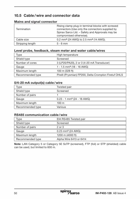
10.5 Cable / wire and connector data
Mains and signal connector
Rising clamp plug-in terminal blocks with screwedTermination connectors (Use only the connectors supplied by Spirax Sarco Ltd. – Safety and Approvals may be compromised otherwise).
Cable size 0.2 mm² (24 AWG) to 2.5 mm² (14 AWG).
Stripping length 5 - 6 mm
Level probe, feedback, steam meter and water cable/wiresType High temperature
Shield type Screened
Number of cores 3 (LP20/PA20), 2 or 3 (4-20 mA Transducer)
Gauge 1 - 1.5 mm² (18 - 16 AWG)
Maximum length 100 m (328 ft)
Recommended type Pirelli (Prysmian) FP200, Delta Crompton Firetuf OHLS
0/4-20 mA output(s) cable / wireType Twisted pair
Shield type Screened
Number of pairs 1
Gauge 0.23 - 1 mm² (24 - 18 AWG)
Maximum length 100 m
Recommended type Various
RS485 communication cable / wireType EIA RS485 Twisted pair
Shield type Screened
Number of pairs 2 or 3
Gauge 0.23 mm² (24 AWG)
Maximum length 1200 m (4000 ft)
Recommended type Alpha Wire 6413 or 6414
Note: LAN Category 5 or Category 5E ScTP (screened), FTP (foil) or STP (shielded) cable can be used, but limited to 600 m.
IM-P402-128 AB Issue 4 51
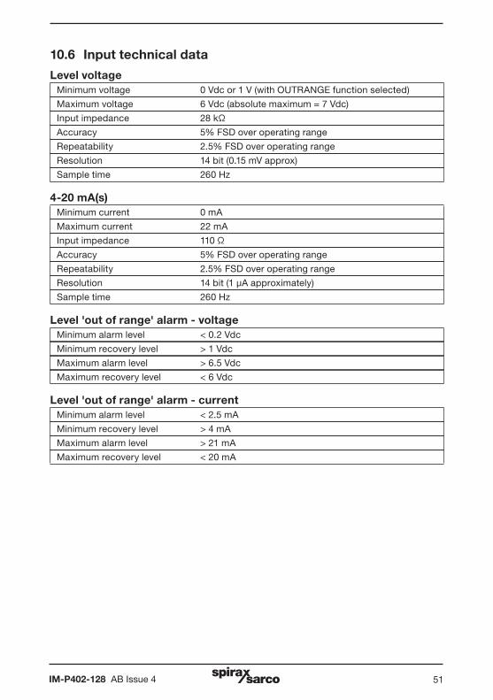
10.6 Input technical data
Level voltageMinimum voltage 0 Vdc or 1 V (with OUTRANGE function selected)
Maximum voltage 6 Vdc (absolute maximum = 7 Vdc)
Input impedance 28 kΩ
Accuracy 5% FSD over operating range
Repeatability 2.5% FSD over operating range
Resolution 14 bit (0.15 mV approx)
Sample time 260 Hz
4-20 mA(s)Minimum current 0 mA
Maximum current 22 mA
Input impedance 110 Ω
Accuracy 5% FSD over operating range
Repeatability 2.5% FSD over operating range
Resolution 14 bit (1 µA approximately)
Sample time 260 Hz
Level 'out of range' alarm - voltageMinimum alarm level < 0.2 Vdc
Minimum recovery level > 1 Vdc
Maximum alarm level > 6.5 Vdc
Maximum recovery level < 6 Vdc
Level 'out of range' alarm - currentMinimum alarm level < 2.5 mA
Minimum recovery level > 4 mA
Maximum alarm level > 21 mA
Maximum recovery level < 20 mA
IM-P402-128 AB Issue 452
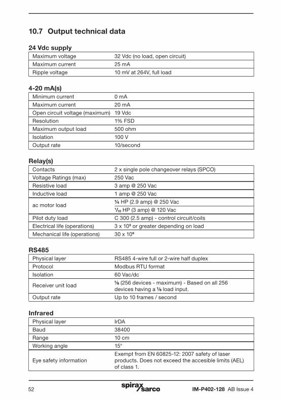
10.7 Output technical data
24 Vdc supplyMaximum voltage 32 Vdc (no load, open circuit)
Maximum current 25 mA
Ripple voltage 10 mV at 264V, full load
4-20 mA(s) Minimum current 0 mA
Maximum current 20 mA
Open circuit voltage (maximum) 19 Vdc
Resolution 1% FSD
Maximum output load 500 ohm
Isolation 100 V
Output rate 10/second
Relay(s)Contacts 2 x single pole changeover relays (SPCO)
Voltage Ratings (max) 250 Vac
Resistive load 3 amp @ 250 Vac
Inductive load 1 amp @ 250 Vac
ac motor load ¼ HP (2.9 amp) @ 250 Vac
1/10 HP (3 amp) @ 120 Vac
Pilot duty load C 300 (2.5 amp) - control circuit/coils
Electrical life (operations) 3 x 10⁵ or greater depending on load
Mechanical life (operations) 30 x 106
RS485 Physical layer RS485 4-wire full or 2-wire half duplex
Protocol Modbus RTU format
Isolation 60 Vac/dc
Receiver unit load (256 devices - maximum) - Based on all 256 devices having a load input.
Output rate Up to 10 frames / second
Infrared Physical layer IrDA
Baud 38400
Range 10 cm
Working angle 15°
Exempt from EN 60825-12: 2007 safety of laser Eye safety information products. Does not exceed the accesible limits (AEL) of class 1.
IM-P402-128 AB Issue 4 53
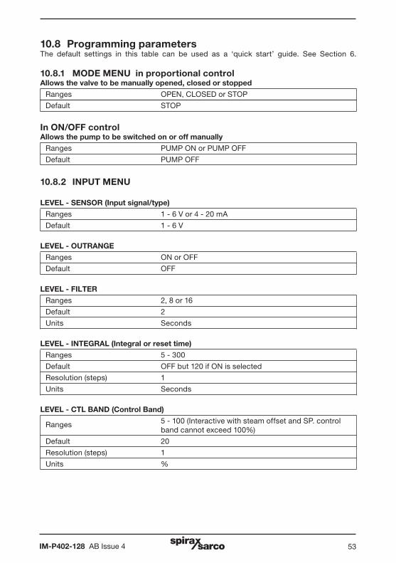
10.8 Programming parametersThe default settings in this table can be used as a ‘quick start’ guide. See Section 6.
10.8.1 MODE MENU in proportional controlAllows the valve to be manually opened, closed or stopped
Ranges OPEN, CLOSED or STOP
Default STOP
In ON/OFF controlAllows the pump to be switched on or off manually
Ranges PUMP ON or PUMP OFF
Default PUMP OFF
10.8.2 INPUT MENU
LEVEL - SENSOR (Input signal/type)
Ranges 1 - 6 V or 4 - 20 mA
Default 1 - 6 V
LEVEL - OUTRANGE
Ranges ON or OFF
Default OFF
LEVEL - FILTER
Ranges 2, 8 or 16
Default 2
Units Seconds
LEVEL - INTEGRAL (Integral or reset time)
Ranges 5 - 300
Default OFF but 120 if ON is selected
Resolution (steps) 1
Units Seconds
LEVEL - CTL BAND (Control Band)
Ranges 5 - 100 (Interactive with steam offset and SP. control band cannot exceed 100%)
Default 20
Resolution (steps) 1
Units %
IM-P402-128 AB Issue 454
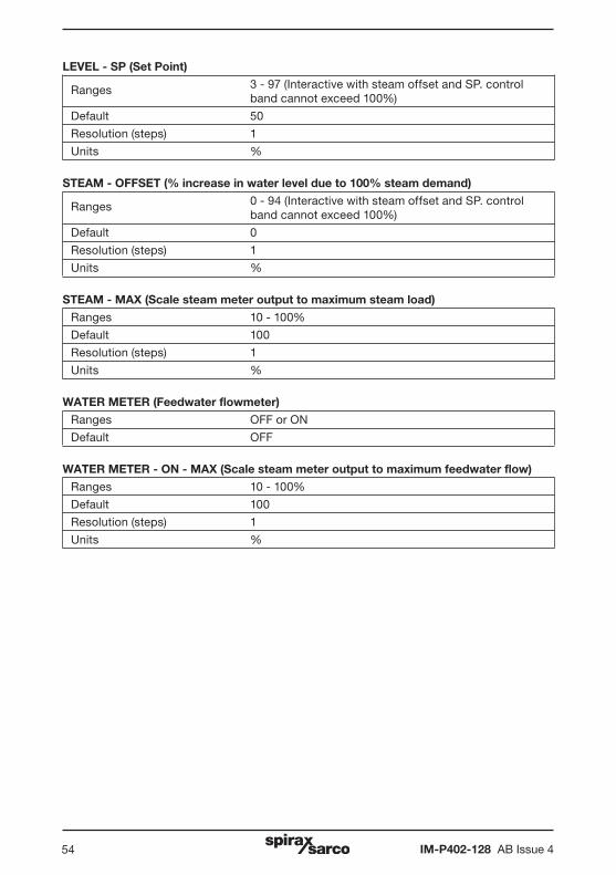
LEVEL - SP (Set Point)
Ranges 3 - 97 (Interactive with steam offset and SP. control band cannot exceed 100%)
Default 50
Resolution (steps) 1
Units %
STEAM - OFFSET (% increase in water level due to 100% steam demand)
Ranges 0 - 94 (Interactive with steam offset and SP. control band cannot exceed 100%)
Default 0
Resolution (steps) 1
Units %
STEAM - MAX (Scale steam meter output to maximum steam load)
Ranges 10 - 100%
Default 100
Resolution (steps) 1
Units %
WATER METER (Feedwater flowmeter)
Ranges OFF or ON
Default OFF
WATER METER - ON - MAX (Scale steam meter output to maximum feedwater flow)
Ranges 10 - 100%
Default 100
Resolution (steps) 1
Units %
IM-P402-128 AB Issue 4 55
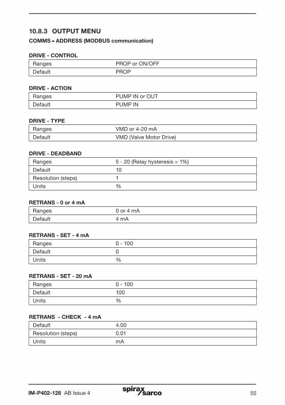
10.8.3 OUTPUT MENUCOMMS - ADDRESS (MODBUS communication)
DRIVE - CONTROL
Ranges PROP or ON/OFF
Default PROP
DRIVE - ACTION
Ranges PUMP IN or OUT
Default PUMP IN
DRIVE - TYPE
Ranges VMD or 4-20 mA
Default VMD (Valve Motor Drive)
DRIVE - DEADBAND
Ranges 5 - 20 (Relay hysteresis = 1%)
Default 10
Resolution (steps) 1
Units %
RETRANS - 0 or 4 mA
Ranges 0 or 4 mA
Default 4 mA
RETRANS - SET - 4 mA
Ranges 0 - 100
Default 0
Units %
RETRANS - SET - 20 mA
Ranges 0 - 100
Default 100
Units %
RETRANS - CHECK - 4 mA
Default 4.00
Resolution (steps) 0.01
Units mA

IM-P402-128 AB Issue 456
RETRANS - CHECK - 20 mADefault 20.00
Resolution (steps) 0.01
Units mA
POSITION (positioner) - 0 or 4 mARanges 0 or 4 mA
Default 4 mA
POSITION (positioner) - SET - 4 mARanges 0 - 100
Default 0
Units %
POSITION (positioner) - SET - 20 mARanges 0 - 100
Default 100
Units %
POSITION (positioner) - CHECK - 4 mADefault 4.00
Resolution (steps) 0.01
Units mA
POSITION (positioner) - RETRANS - CHECK - 20 mADefault 20.00
Resolution (steps) 0.01
Units mA
COMMS - ADDRESSRanges 001 - 247
Default 001
COMMS - BAUDRanges 1200, 9600 or 19200
Default 9600
Units BAUD or bits/second
COMMS - IR (Infrared)Ranges MASTER or SLAVE
Default SLAVE
COMMS - IR UNITS IN NETWORKRanges 1 - 8
IM-P402-128 AB Issue 4 57
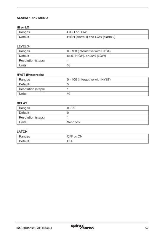
ALARM 1 or 2 MENU
HI or LO
Ranges HIGH or LOW
Default HIGH (alarm 1) and LOW (alarm 2)
LEVEL%
Ranges 0 - 100 (Interactive with HYST)
Default 85% (HIGH), or 20% (LOW)
Resolution (steps) 1
Units %
HYST (Hysteresis)
Ranges 0 - 100 (Interactive with HYST)
Default 5
Resolution (steps) 1
Units %
DELAY
Ranges 0 - 99
Default 0
Resolution (steps) 1
Units Seconds
LATCH
Ranges OFF or ON
Default OFF
IM-P402-128 AB Issue 458
TEST MENU
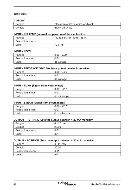
DISPLAYRanges Black-on-white or white-on-blackDefault Black-on-white
INPUT - INT TEMP (Internal temperature of the electronics)Ranges -40 to 85°C or -40 to 185°F Resolution (steps) 1Units °C or °F
INPUT - LEVELRanges 0.00 - 7.00Resolution (steps) 0.01Units dc voltage
INPUT - FEEDBACK (VMD feedback potentiometer from valve)Ranges 0.00 - 2.26Resolution (steps) 0.01Units dc voltage
INPUT - FLOW (Signal from water meter)Ranges 0.00 - 22.73Resolution (steps) 0.01Units dc milliamps
INPUT - STEAM (Signal from steam meter)Ranges 0.00 - 22.73Resolution (steps) 0.01Units dc milliamps
OUTPUT - RETRANS (Sets the output between 4-20 mA manually)Ranges 4 - 20 mADefault 20.00Resolution (steps) 0.01Units mA
OUTPUT - POSITION (Sets the output between 4-20 mA manually)Ranges 4 - 20 mADefault 20.00Resolution (steps) 0.01Units mA
IM-P402-128 AB Issue 4 59
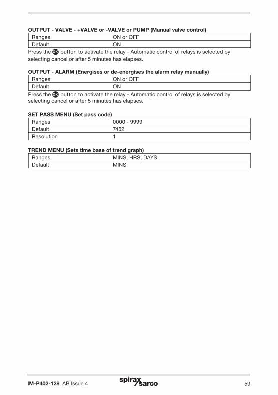
OUTPUT - VALVE - +VALVE or -VALVE or PUMP (Manual valve control)Ranges ON or OFFDefault ON
Press the OK button to activate the relay - Automatic control of relays is selected by selecting cancel or after 5 minutes has elapses.
OUTPUT - ALARM (Energises or de-energises the alarm relay manually)Ranges ON or OFFDefault ON
Press the OK button to activate the relay - Automatic control of relays is selected by selecting cancel or after 5 minutes has elapses.
SET PASS MENU (Set pass code)Ranges 0000 - 9999Default 7452Resolution 1
TREND MENU (Sets time base of trend graph)Ranges MINS, HRS, DAYSDefault MINS
IM-P402-128 AB Issue 460
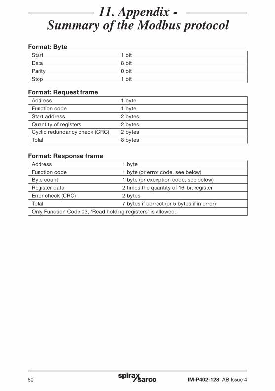
Format: ByteStart 1 bit
Data 8 bit
Parity 0 bit
Stop 1 bit
Format: Request frameAddress 1 byte
Function code 1 byte
Start address 2 bytes
Quantity of registers 2 bytes
Cyclic redundancy check (CRC) 2 bytes
Total 8 bytes
Format: Response frameAddress 1 byte
Function code 1 byte (or error code, see below)
Byte count 1 byte (or exception code, see below)
Register data 2 times the quantity of 16-bit register
Error check (CRC) 2 bytes
Total 7 bytes if correct (or 5 bytes if in error)
Only Function Code 03, 'Read holding registers' is allowed.
11. Appendix - Summary of the Modbus protocol
IM-P402-128 AB Issue 4 61
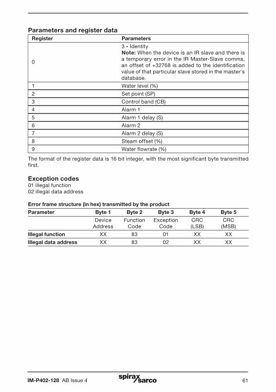
Parameters and register data Register Parameters
3 - Identity Note: When the device is an IR slave and there is a temporary error in the IR Master-Slave comms, an offset of +32768 is added to the identification value of that particular slave stored in the master's database.
1 Water level (%)
2 Set point (SP)
3 Control band (CB)
4 Alarm 1
5 Alarm 1 delay (S)
6 Alarm 2
7 Alarm 2 delay (S)
8 Steam offset (%)
9 Water flowrate (%)
The format of the register data is 16 bit integer, with the most significant byte transmitted first.
Exception codes01 illegal function02 illegal data address
Error frame structure (in hex) transmitted by the product
Parameter Byte 1 Byte 2 Byte 3 Byte 4 Byte 5
Device Function Exception CRC CRC Address Code Code (LSB) (MSB)
Illegal function XX 83 01 XX XX
Illegal data address XX 83 02 XX XX
0

IM-P402-128 AB Issue 462
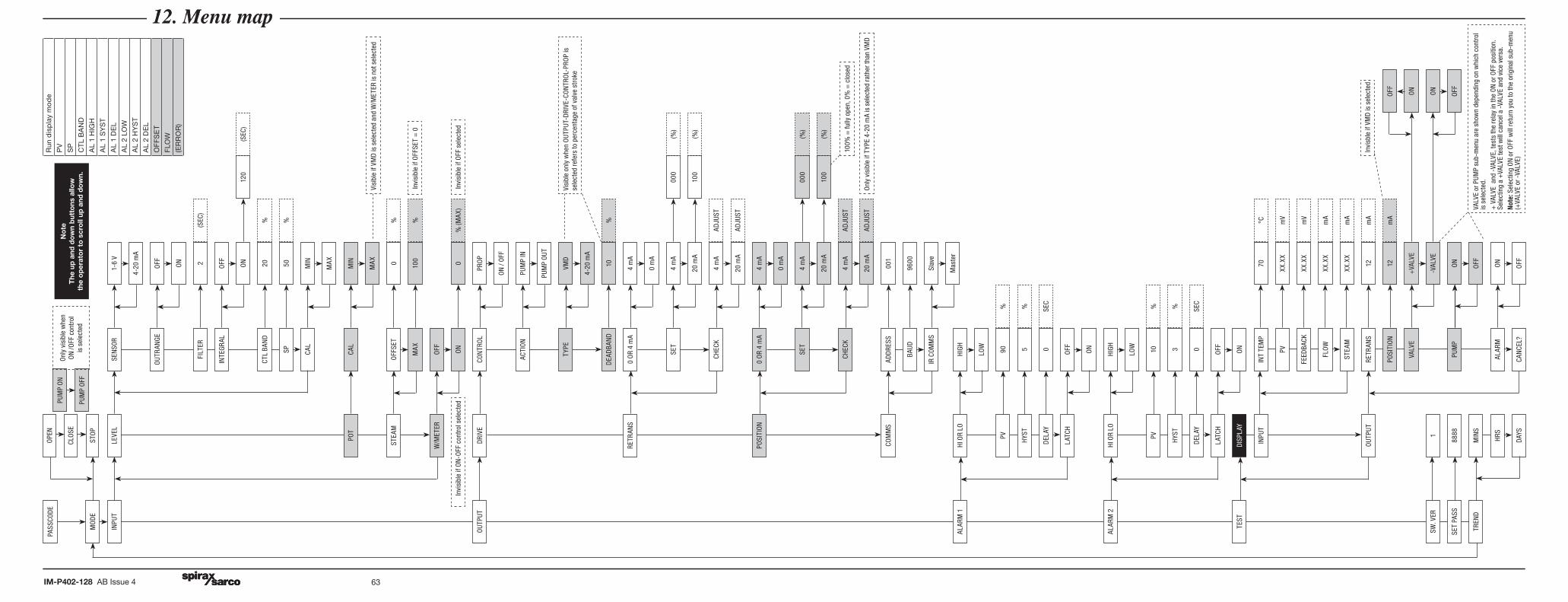
12. Menu map12. Menu map
IM-P402-128 AB Issue 4 63
STO
P
CLO
SE
OPE
N
MO
DE
PASS
COD
E
PUM
P O
FF
PUM
P O
N
LEVE
LIN
PUT
SEN
SOR
1-6
V
4-20
mA
OUT
RAN
GEO
FF ON
FILT
ER2
(SEC
)
INTE
GRAL
OFF ON
120
(SEC
)
CTL
BAN
D20
%
SP50
%
CAL
MIN
MAX
POT
CAL
MIN
MAX
STEA
MO
FFSE
T0 10
0
% %M
AX
W/M
ETER
OFF
0%
(MAX
)O
N
DRI
VECO
NTR
OL
PRO
P
ON
/ OFF
OUT
PUT
ACTI
ON
PUM
P IN
PUM
P O
UT
TYPE
VMD
4-20
mA
10%
DEA
DBA
ND
RETR
ANS
0 O
R 4
mA
4 m
A
0 m
A
000
(%)
SET
4 m
A
100
(%)
20 m
A
CHEC
K4
mA
ADJU
ST
20 m
AAD
JUST
POSI
TIO
N0
OR
4 m
A4
mA
0 m
A
000
(%)
SET
4 m
A
100
(%)
20 m
A
CHEC
K4
mA
ADJU
ST
20 m
AAD
JUST
COM
MS
ADD
RESS
001
9600
BAUD
Slav
eIR
CO
MM
S
ALAR
M 1
HI O
R LO
HIGH
LOW
PV90
%
HYS
T5
%
DEL
AY0
SEC
LATC
HO
FF ON
ALAR
M 2
HI O
R LO
HIGH
LOW
PV10
%
HYS
T3
%
DEL
AY0
SEC
LATC
HO
FF ON
TEST
DIS
PLAY
INPU
TIN
T TE
MP
70
PVXX
.XX
FEED
BACK
XX.X
X
FLO
WXX
.XX
STEA
MXX
.XX
mV
mV
mA
mA
OUT
PUT
RETR
ANS
12m
A
POSI
TIO
N12
mA
OFF
VALV
E+
VALV
EO
N
-VAL
VEO
N
OFF
SW. V
ER1
SET
PASS
8888
ON
PUM
P
OFF
ALAR
MO
N
OFF
CAN
CEL?
TREN
DM
INS
HRS
DAY
S
Run
dis
pla
y m
od
e
PV
SP
CT
L B
AN
D
AL
1 H
IGH
AL
1 S
YS
T
AL
1 D
EL
AL
2 LO
W
AL
2 H
YS
T
AL
2 D
EL
OFF
SE
T
FLO
W
(ER
RO
R)
Vis
ible
if V
MD
is s
elec
ted
and
W/M
ETER
is n
ot s
elec
ted
In
visi
ble
if O
FFSE
T =
0
In
visi
ble
if O
FF s
elec
ted
In
visi
ble
if O
N-O
FF c
ontr
ol s
elec
ted
Visi
ble
only
whe
n O
UTPU
T-D
RIVE
-CO
NTR
OL-
PRO
P is
se
lect
ed re
fers
to p
erce
ntag
e of
val
ve s
trok
e
100%
= fu
lly o
pen,
0%
= c
lose
d
Onl
y vi
sibl
e if
TYPE
4-2
0 m
A is
sel
ecte
d ra
ther
than
VM
D
Invi
sble
if V
MD
is s
elec
ted
VALV
E or
PUM
P su
b-m
enu
are
show
n de
pend
ing
on w
hich
con
trol
is
sel
ecte
d.+
VAL
VE a
nd -
VALV
E, te
sts
the
rela
y in
the
ON
or O
FF p
ositi
on.
Sele
ctin
g a
+VA
LVE
test
will
can
cel a
-VA
LVE
and
vice
ver
sa.
Not
e: S
elec
ting
ON
or O
FF w
ill re
turn
you
to th
e or
igin
al s
ub-m
enu
(+VA
LVE
or -
VALV
E)
Mas
ter
°C
Onl
y vi
sibl
e w
hen
ON
/OFF
con
trol
is
sel
ecte
d
No
te
The
up
and
do
wn
but
tons
allo
w
th
e o
per
ato
r to
scr
oll
up a
nd d
ow
n.

IM-P402-128 AB Issue 464