
Sługa Boży Ks. Franciszek Blachnicki Ks. Franciszek Blachnicki
Upload
jovanka-jadrovskaCategory
view
213download
0
7/28/2019 KS-EN030
http://slidepdf.com/reader/full/ks-en030 1/17
HYDRAULIC EXCAVATOR
ZAXIS-3 series
HYDRAULIC EXCAVATOR:
::
:
Model Code
Engine Rated PowerOperating Weight
ZX500LC-3 / ZX520LCH-3
260 kW (349 HP)ZX500LC-3 : 49 500 kgZX520LCH-3 : 51 700 kg
Backhoe Bucket SAE, PCSA Heaped :ZX500LC-3 : 1.15 - 2.65 m3
ZX520LCH-3 : 1.90 - 2.65 m3
CECE Heaped :ZX500LC-3 : 1.00 - 2.30 m3
ZX520LCH-3 : 1.70 - 2.30 m3
7/28/2019 KS-EN030
http://slidepdf.com/reader/full/ks-en030 2/17
2 3
Durability and reliability
Increased loading capacity of swing
circle
Enlarged upper and lower rollers, idlers
and sprockets
Increased traction force
Pressed master pins
Full track guard provided standard
(ZAXIS 520LCH)
5 % increase in strength with stronger
pin material
Strengthened general-purpose bucket
Strengthened H-bucket for heavy-duty
Productivity
Increased digging force
Enhanced boom recirculation system
Boom mode selector
Larger-diameter front piping
Combined operation of boom and arm
New bucket regenerative system
High power yet low fuel consumption
Common rail type fuel injection system
Cooled EGR system
Operator comfort
High visibility inside cab
Short stroke levers
Wide foot space
Comfort designed seat
Improved controlability and operator
comfort
Page 4-5
Page 6-7
Multi function monitor
Maintenance support
Attachment support system
Multi-language selection
Rear view camera (optional)
Theft deterrent system
Fuel consumption monitoring
Page 8-9
Maintenance
Parallel arrangement of the cooling
pack
Conveniently located inspection points
Automatic lubrication (optional) /
repositioned bucket lubricating points
Enlarged fuel tank
Extended hydraulic oil lter change
intervals
Page 12-13
Page 10-11
Safety measures
CRES II cab
(ZAXIS 500LC is standard equipped)
H/R cab
(ZAXIS 520LCH is standard equipped)
Cab right guard
Evacuation hammer
Pilot control shut-off lever
Environment measures
A cleaner machine
A quieter machine
A recyclable machine
Page 14
Parts & service
Page 16-17
Page 15
Specifcations
Page 18-31
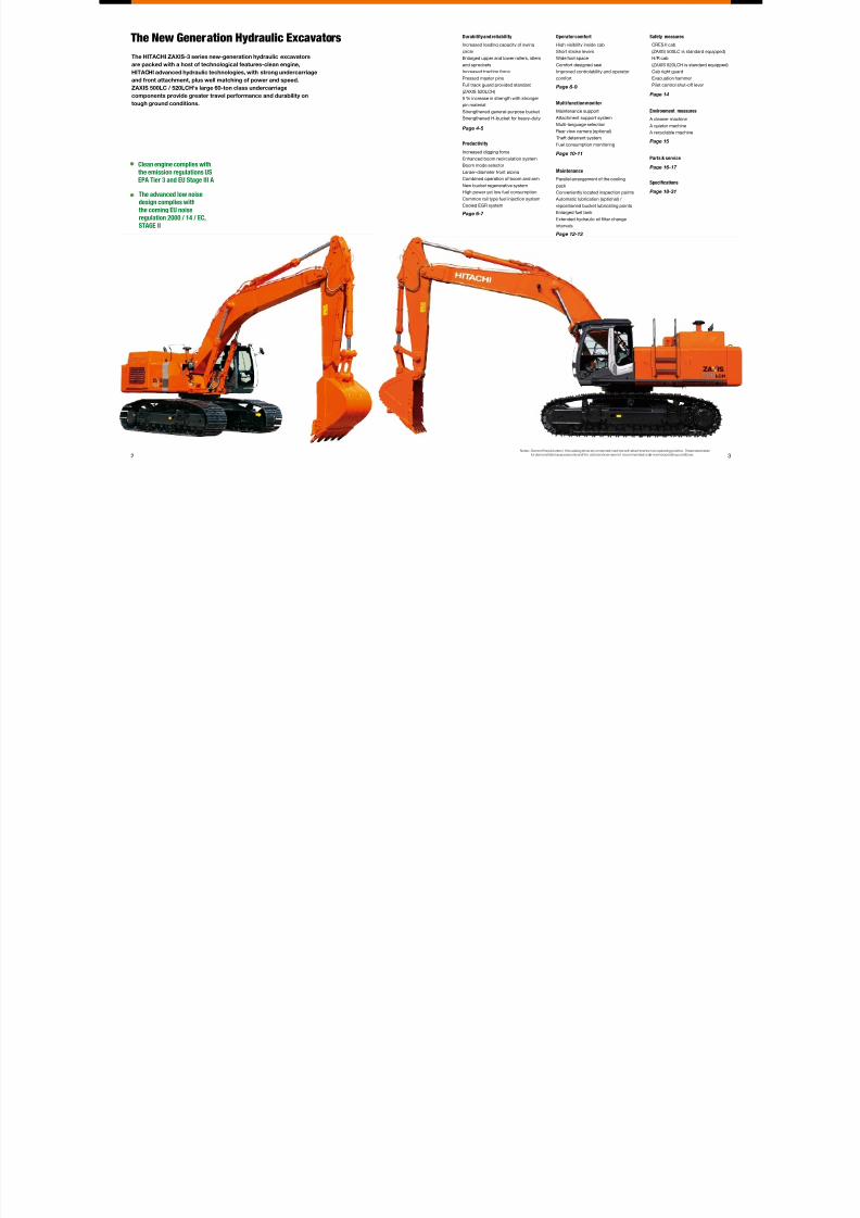
The New Generation Hydraulic Excavators
The HITACHI ZAXIS-3 series new-generation hydraulic excavators
are packed with a host of technological features-clean engine,
HITACHI advanced hydraulic technologies, with strong undercarriage
and front attachment, plus well matching of power and speed.
ZAXIS 500LC / 520LCH's large 60-ton class undercarriage
components provide greater travel performance and durability on
tough ground conditions.
Clean engine complies withthe emission regulations US
EPA Tier 3 and EU Stage III A
The advanced low noise
design complies with
the coming EU noise
regulation 2000 / 14 / EC,
STAGE II
Notes : Some of the pictures in this catalog show an unmanned machine with attachments in an operating position. These were takenfor demonstration purposes only and the actions shown are not recommended under normal operating conditions.

7/28/2019 KS-EN030
http://slidepdf.com/reader/full/ks-en030 3/17
54
Increased Loading Capacity of Swing
Circle
The number of ball bearings in the
swing circle, which sustains the
upperstructure, is increased to boost
the loading capacity of the swing circle
by approximately 6 %, allowing stable
swing even in tough operation.
(vs. Conventional ZAXIS 480MT /
480MTH)
Pressed Master Pins
Increased Traction Force
Strengthened Front Components
Strengthened Undercarriage
Strengthened undercarriage for higher durability even in
heavy-duty applications.
A Solid Base for a Long Life
Enlarged Upper and Lower Rollers,
Idlers and Sprockets
Upper and lower rollers, idlers and
sprockets, used on the ZAXIS 500LC
/ 520LCH, are larger in diameter than
those on the new ZAXIS 450LC /
470LCH. Undercarriage components
capable of bearing a 60-ton class
excavator are utilized to give sufcient
strength and durability. This feature is
suitable for worksites when the machine
travels frequently.
Full Track Guard Provided Standard
(ZAXIS 520LCH)
On the H-specication machine, full
track guards are provided standard.
Full track guards protect track links
and lower rollers from damage and
deformation.
Moreover, they also keep out stones,
preventing the overload to the
undercarriage to reduce wear and
damage.
The master pin of each track link is
pressed, instead of master pin using a
pin retention to avoid disengagement.
On the ZAXIS 500LC / 520LCH,
distance between tumblers is
shortened, compared to that of the new
ZAXIS 450LC / 470LCH, to increase
traction force by 30 %.
The feature is suitable for frequent hill
climbing and traveling on hard ground
surfaces.
5 % Increase in Strength with Stronger
Pin Material
The strength of pins, used in the arm
and boom, is increased by 5 %, using
harder steel material.
(vs. Conventional ZAXIS 480MT /
480MTH)
Strengthened General-Purpose Bucket
Bucket teeth are reshaped as Super-V
teeth for smooth penetration and higher
production. Bushings are utilized at
both ends of a bucket pin to eliminate
clearances, preventing jerky operation.
Strengthened H-Bucket for Heavy-Duty
The heavy-duty bucket is reshaped,
and bucket parts are strengthened to
increase durability.
7/28/2019 KS-EN030
http://slidepdf.com/reader/full/ks-en030 4/17
7
15% UP
Fuel Filter
Fuel Pump
Common Rail Pressure Sensor
Common Rail
Fuel Tank Control UnitInjector
ONComfortable mode
Thereis littleliftingor pullingofthebody
sothereis less vibration andshock.
OFFPowerful mode
Much liftingandpullingofthebody so
thereis morevibration andshock.
P
M
Arm Raise
Bucket Roll-Out
Swing
Boom Lower
6
Coolant
EGR Cooler
ControlUnit
Intake
EGRControl Valve
Cylinder Head
Exhaust
Development Concept of New Engine
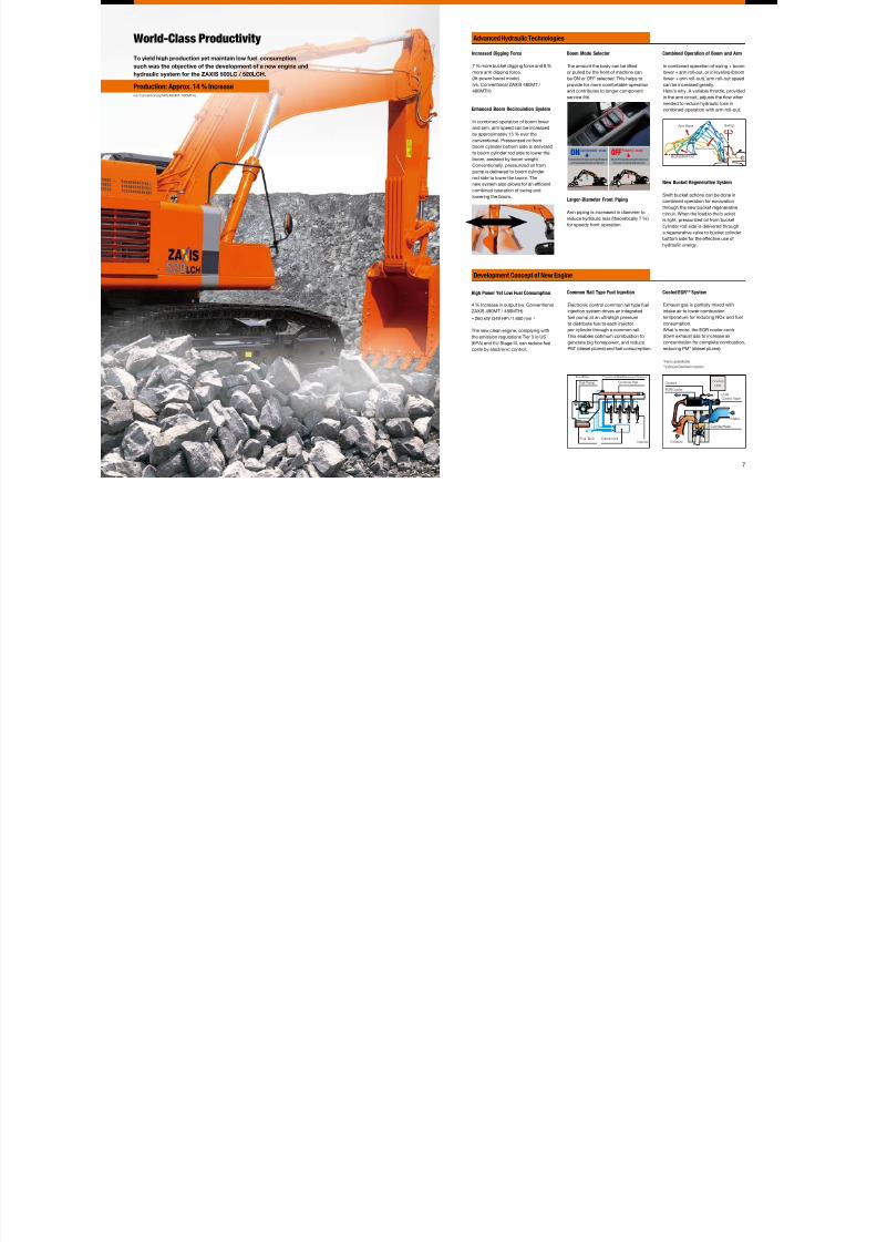
Advanced Hydraulic Technologies
To yield high production yet maintain low fuel consumption,
such was the objective of the development of a new engine and
hydraulic system for the ZAXIS 500LC / 520LCH.
World-Class Productivity Increased Digging Force
7 % more bucket digging force and 8 %
more arm digging force.
(At power boost mode)
(vs. Conventional ZAXIS 480MT /
480MTH)
Boom Mode Selector
The amount the body can be lifted
or pulled by the front of machine can
be ON or OFF selected. This helps to
provide for more comfortable operation
and contributes to longer component
service life.
Enhanced Boom Recirculation System
In combined operation of boom lower
and arm, arm speed can be increased
by approximately 15 % over the
conventional. Pressurized oil from
boom cylinder bottom side is delivered
to boom cylinder rod side to lower the
boom, assisted by boom weight.
Conventionally, pressurized oil from
pump is delivered to boom cylinder
rod side to lower the boom. The
new system also allows for an efcient
combined operation of swing and
lowering the boom.Larger-Diameter Front Piping
Arm piping is increased in diameter to
reduce hydraulic loss (theoretically 7 %)
for speedy front operation.
New Bucket Regenerative System
Swift bucket actions can be done in
combined operation for excavation
through the new bucket regenerative
circuit. When the load to the b ucket
is light, pressurized oil from bucket
cylinder rod side is delivered through
a regenerative valve to bucket cylinder
bottom side for the effective use of
hydraulic energy.
Common Rail Type Fuel Injection
Electronic control common rail type fuel
injection system drives an integrated
fuel pump at an ultrahigh pressure
to distribute fuel to each injector
per cylinder through a common rail.
This enables optimum combustion togenerate big horsepower, and reduce
PM* (diesel plume) and fuel consumption.
Cooled EGR** System
Exhaust gas is partially mixed with
intake air to lower combustion
temperature for reducing NOx and fuel
consumption.
What's more, the EGR cooler cools
down exhaust gas to increase airconcentration for complete combustion,
reducing PM* (diesel plume).
*Particulate Matter
**Exhaust Gas Recirculation
Production: Approx. 14 % Increase(vs. Conventional ZAXIS 480MT / 480MTH)
Combined Operation of Boom and Arm
In combined operation of swing + boom
lower + arm roll-out, or in leveling (boom
lower + arm roll-out), arm roll-out speed
can be increased greatly. Here's why. A variable throttle, provided
in the arm circuit, adjusts the ow when
needed to reduce hydraulic loss in
combined operation with arm roll-out.
High Power Yet Low Fuel Consumption
4 % Increase in output (vs. Conventional
ZAXIS 480MT / 480MTH)
260 kW (349 HP) /1 800 min -1
The new clean engine, complying with
the emission regulations Tier 3 in US(EPA) and EU Stage III, can reduce fuel
costs by electronic control.
7/28/2019 KS-EN030
http://slidepdf.com/reader/full/ks-en030 5/17
8 9
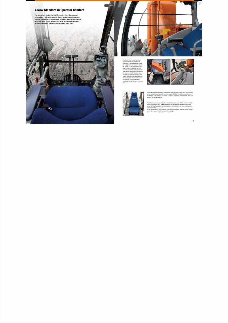
The operator's seat of the ZAXIS-3 series gives the operator
an excellent view of the jobsite. On the widescreen colour LCD
monitor the operator can see what is behind the machine. Ample
legroom, short stroke levers and a large seat ensure optimum
working conditions for the operator during long hours.
A New Standard in Operator Comfort
The ZAXIS-3 series cab has been
redesigned to meet demands of
customers. From the operator's seat
the operator has an excellent view of
the jobsite. On the widescreen color
LCD monitor the operator can see
machine conditions and with the rear
view camera (optional), what is behind
the machine. Ample legroom, short
stroke levers and a suspension seat
ensure optimum working conditions.
The seat features horizontal, vertical
adjustments and has a backrest
contoured for comfort, with a HITACHI
logo.
Wide adjustable armrests and a retractable seat belt are included. Short stroke levers
allow for continuous operation with less fatigue. The cab is pressurized to keep out
dust. Noise and vibrations are kept to a minimum due to the elastic mounts, lled with
silicone oil, the cab rests on.
Visibility is improved especially for the right downward view. Sliding windows on the
front (ZAXIS 500LC) and side enable direct communication between operator and
other workers. Foot space has increased and travel pedals have been redesigned for
easier operation.
A at oor allows for easy cleaning. Ergonomic controls and switches, fully automatic
air conditioner and a radio complete the package.

7/28/2019 KS-EN030
http://slidepdf.com/reader/full/ks-en030 6/17
10 11
Excavation: Work mode selection window
Breaker 1:Selected for small-ow breaker
Breaker 2:Selected for medium-ow breaker
Breaker 3:Selected for large-ow breaker
Embedded Information Technology
The ZAXIS-3 series is equipped with a widescreen color LCD
monitor with adjustable contrast for day and night shifts. With
the monitor the operator can check maintenance intervals,
select work modes, monitor fuel consumption, and connect
to the rear view camera (optional). A theft deterrent system and
multi-language selection is also available.
Multi Function Monitor
Attachment support system
(work mode selector)
The color LCD monitor, located in the
cab, indicates coolant temperature,
fuel level, and maintenance data. It also
allows one-touch adjustment of the
attachment. The display can also be
adjusted to day or night shift.
The work mode can be selected from
the multi-function monitor inside the
cab. Pump ow in the selected work
mode can be monitored.
Maintenance support
Replacement timing of hydraulic oil
and fuel lters is alerted to the operator
through the LCD monitor according to
the schedule preset by the user each
time when turning the key switch.The scheduled maintenance can
prevent the failure of the machine.
Multi-language Selection
Theft Deterrent system
Rear View Camera (Optional)
Fuel Consumption Monitoring
The widescreen color LCD, teamed
up with the rear view camera on the
counterweight, gives the operator
unobstructed rearward viewing.
The rear view camera automatically
works when traveling, and can also be
manually turned on with a select switch
on the monitor.
Fuel consumption per operating hour is
computed, and the result is displayed
on the LCD monitor. This information
suggests refuelling timing, and guides
energy-saving operation and efcient
job management.
The electronic immobiliser requires the
entry of an encryption code to the
multifunctional monitor each time when
starting the engine to prevent theft and
vandalism.
The menu allows selection from 12
languages.
7/28/2019 KS-EN030
http://slidepdf.com/reader/full/ks-en030 7/17
13
Easy removal of debris and dirtfrom blower, etc. Engine
Radiator Oil Cooler
Intercooler
Parallel Arrangement
12
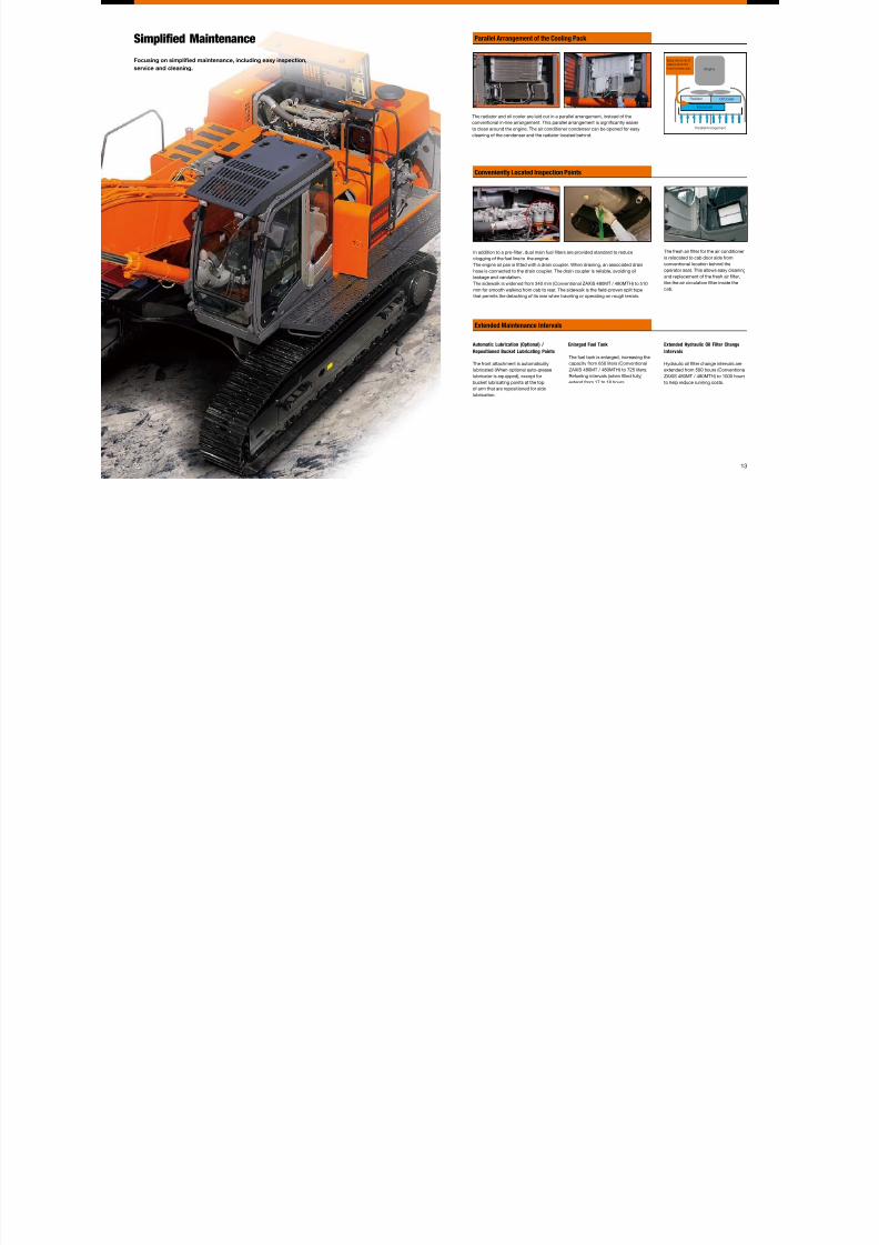
Simplifed Maintenance
Focusing on simplifed maintenance, including easy inspection,
service and cleaning.
The fresh air lter for the air conditioner
is relocated to cab door side from
conventional location behind the
operator seat. This allows easy cleaning
and replacement of the fresh air lter,
like the air circulation lter inside the
cab.
In addition to a pre-lter, dual main fuel lters are provided standard to reduce
clogging of the fuel line to the engine.
The engine oil pan is tted with a drain coupler. When draining, an associated drain
hose is connected to the drain coupler. The drain coupler is reliable, avoiding oil
leakage and vandalism.
The sidewalk is widened from 340 mm (Conventional ZAXIS 480MT / 480MTH) to 510
mm for smooth walking from cab to rear. The sidewalk is the eld-proven split type
that permits the detaching of its rear when traveling or operating on rough terrain.
The radiator and oil cooler are laid out in a parallel arrangement, instead of the
conventional in-line arrangement. This parallel arrangement is signicantly easier
to clean around the engine. The air conditioner condenser can be opened for easy
cleaning of the condenser and the radiator located behind.
Extended Hydraulic Oil Filter Change
Intervals
Hydraulic oil lter change intervals are
extended from 500 hours (Conventional
ZAXIS 480MT / 480MTH) to 1000 hours
to help reduce running costs.
Enlarged Fuel Tank
The fuel tank is enlarged, increasing the
capacity from 650 liters (Conventional
ZAXIS 480MT / 480MTH) to 725 liters.
Refueling intervals (when lled fully)
extend from 17 to 18 hours.
Automatic Lubrication (Optional) /
Repositioned Bucket Lubricating Points
The front attachment is automatically
lubricated (When optional auto-grease
lubricator is equipped), except for
bucket lubricating points at the top
of arm that are repositioned for side
lubrication.
Parallel Arrangement of the Cooling Pack
Conveniently Located Inspection Points
Extended Maintenance Intervals
7/28/2019 KS-EN030
http://slidepdf.com/reader/full/ks-en030 8/17
14 15
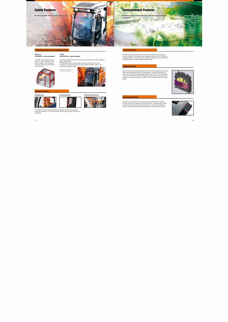
Safety Features
An array of safety devices for enhanced safety.
Cab Right Guard
Other features include a retractable seatbelt, evacuation hammer and emergency
engine shut-off switch. A shut-off lever for pilot control helps to prevent unintentional
movements.
CRES II Cab
(ZAXIS 500LC is standard equipped)
The CRES II cab is designed to help
with "just in case" protection for the
operator. Safety in case of tipping is
improved. The cab top can withstand
nine-fold loading.
H/R Cab
(ZAXIS 520LCH is standard equipped)
The H/R cab utilizes the reinforced front window and FOPS* at the roof for protection
against falling objects.
The front glass window, made of straight-laminated, is xed to shut out dirt
and debris. The cab provided with a full guard satises the OPG**( Level II ) cab
requirements stipulated by ISO.
*Falling Object Protective Structure
**Operator Protective Guards
Evacuation Hammer Pilot Control Shut-Off Lever
Environmental Features
Boarding a clean engine complying with the rigorous emission
regulations.
The ZAXIS-3 series is equipped with a clean but powerful engine to comply with
Tier 3, and Stage III A. An engine emission regulations effective in the U.S. EPA and
European Union from 2006. Exhaust gas is partly re-combusted to reduce particulate
matter (PM) output and lower nitrogen oxide (NOx) levels.
Engine noise is reduced by approximately 2 dB with the robust engine. It goes without
saying that the engine meets the EU noise regulations. The engine cooling fan is a
large 1 120 mm diameter variable-speed electro-hydraulic fan. This fan automatically
starts when temperature comes into the high temperature range, ensuring low noise
operation. A proven large mufer is provided to reduce sound and exhaust emissions
greatly.
Over 97 % of the ZAXIS-3 series can be recycled. All resin parts are marked to
facilitate recycling. The machine is completely lead-free. The radiator and oil cooler
are made from aluminium and all wires are lead-less. In addition, biodegradable
hydraulic oil is available for jobsites where special environmental care is required.
Protecting the Operator From Tipping Accident
Additional Features
A Cleaner Machine
A Quieter Machine
A Recyclable Machine
7/28/2019 KS-EN030
http://slidepdf.com/reader/full/ks-en030 9/17
17
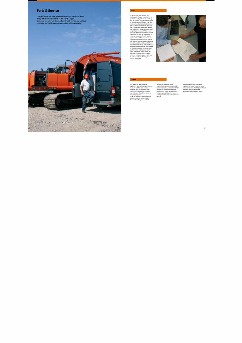
Machine includes optional equipment installed by customer.
Parts
Service
16
Parts & Service
Over the years, we have gained experience in one of the most
competitive service markets in the world - Japan.
Using our know-how in dealing directly with customers, we have
created a worldwide support system that is highly capable.
HITACHI only offers genuine high
quality parts. We guarantee that these
parts have high performance and long
life. We manage around 1 000 000 types
of parts all around the world. They are
designed and built to be the best match
for your HITACHI equipment. HITACHI
has a global parts distribution network
that makes sure you get what you need
as quickly as possible. We have more
than 150 dealers worldwide who provide
the closest support for your needs. In
most cases, your dealer will have the
replacement part that you require. If a
dealer does not have a certain part, he
can order it from four fully stocked parts
depots located across the world. These
distribution centers are all connected by
a on-line system that gives them accessto shared information on stocks, such
as the number and type of available
parts. The depots, which in turn are
stocked by a parts center in Japan,
minimize delivery time and enable you
to get your parts as efciently and
quickly as possible.
Our goal is to "keep customer
equipment at a maximum performance
level". To full this goal, we have
set more than 150 dealers all over
the world. They have highly trained
technicians, and provide a number ofsupport programs.
HITACHI provides a unique extended
warranty program called HITACHI
Extended Life Program, or HELP.
To minimize downtime during
troubleshooting, we developed a PDA
based diagnostic system called "Dr.ZX".
To keep our customers' equipment
in top running shape, good service is
indispensable. We believe personneltraining is the key to providing the best
service.
If you would like more information
regarding parts and/or service, please
ask your nearest H ITACHI dealer. Not all
programs and/or services are
available in every market or region.
7/28/2019 KS-EN030
http://slidepdf.com/reader/full/ks-en030 10/17
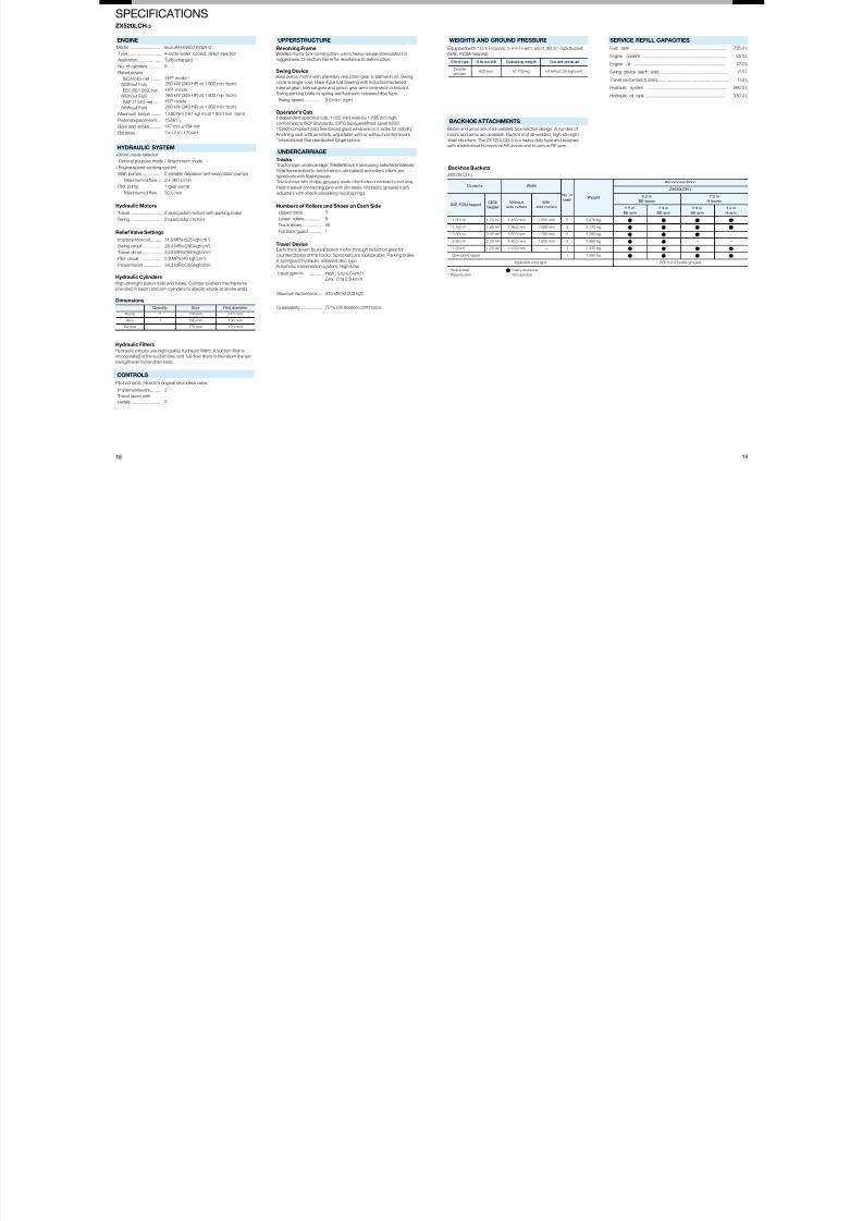
SPECIFICATIONS
8 19
X520LCH-3
ZX520LCH-3
Capacity Width
No. of
teethWeight
Recommendation
ZX520LCH-3
SAE, PCSA heapedCECE
heaped
Without
side cutters
With
side cutters
6.3 m
BE-boom
7.0 m
H-boom
2.5 m
BE-arm
2.9 m
BE-arm
2.9 m
BE-arm
3.4 m
H-arm
*1 1.90 m3 1.70 m3 1 480 mm 1 500 mm 5 2 070 kg
*1 2.10 m3 1.80 m3 1 560 mm 1 580 mm 5 2 170 kg
*1 2.30 m3 2.00 m3 1 680 mm 1 700 mm 5 2 260 kg —
*1 2.50 m3 2.20 m3 1 800 mm 1 820 mm 5 2 360 kg — —
*2 1.30 m3 1.20 m3 1 170 mm — 3 2 330 kg
One-point ripper 1 1 260 kg
Applicable shoe type 600 mm Double grouser
*1 Rock bucket Heavy-duty service*2 Ripper bucket — Not applicable
Model ...........................
Type ............................
Aspiration ....................
No. of cylinders ...........
Rated power
ISO 9249, net ........
(Without Fan)
EEC 80/1269, net ..
(Without Fan)
SAE J1349, net .....
(Without Fan)
Maximum torque .........
Piston displacement ....
Bore and stroke...........
Batteries......................
Main pumps ................
Maximum oil ow...
Pilot pump...................
Maximum oil ow...
Travel ..........................
Swing ..........................
mplement circuit .........
Swing circuit................
Travel circuit ................
Pilot circuit ..................
Power boost ...............
Quantity Bore Rod diameter
Boom 2 170 mm 115 mm
Arm 1 190 mm 130 mm
Bucket 1 170 mm 120 mm
mplement levers .........
Travel levers with
pedals .........................
Swing speed ...............
Upper rollers................
Lower rollers................
Track shoes .................
Full track guard ...........
Travel speeds ...............
Maximum traction force ....
Gradeability....................
S ho e t ype S ho e w id th O pe ra ti ng we ig ht G ro und pre ss ure
Double
grouser600 mm 51 700 kg 91 kPa (0.93 kgf/cm2)
Fuel tank ...................................................................................
Engine coolant ..........................................................................
Engine oil ..................................................................................
Swing device (each side) ...........................................................
Travel device (each side) ............................................................
Hydraulic system .......................................................................
Hydraulic oil tank .......................................................................
Isuzu AH-6WG1XYSA-01
4-cycle water-cooled, direct injection
Turbocharged
6
H/P mode :
260 kW (349 HP) at 1 800 min-1(rpm)
H/P mode :
260 kW (349 HP) at 1 800 min-1(rpm)
H/P mode :
260 kW (349 HP) at 1 800 min-1(rpm)
1 580 Nm (161 kgf m) at 1 50 0 min-1(rpm)
15.681 L
147 mm x 154 mm
2 x 12 V / 170 AH
2 variable displacement axial piston pumps
2 x 360 L/min
1 gear pump
30 L/min
HYDRAULIC SYSTEM
Work mode selector
ydraulic Motors
2 axial piston motors with parking brake
2 axial piston motors
elief Valve Settings
31.9 MPa (325 kgf/cm2)
28.4 MPa (290 kgf/cm2)
34.3 MPa (350 kgf/cm2)
3.9 MPa (40 kgf/cm2)
ydraulic Cylinders
gh-strength piston rods and tubes. Cylinder cushion mechanisms
ovided in boom and arm cylinders to absorb shock at stroke ends.
imensions
ydraulic Filters
ydraulic circuits use high-quality hydraulic lters. A suction lter is
corporated in the suction line, and full-ow lters in the return line and
wing/travel motor drain lines.
CONTROLS
2
2
lot controls. Hitachi's original shockless valve.
ENGINE
Engine speed sensing system
General purpose mode / Attachment mode
34.3 MPa (350 kgf/cm2)
UPPERSTRUCTURE
9.0 min-1 (rpm)
Revolving FrameWelded sturdy box construction, using heavy-gauge steel plates for
ruggedness. D-section frame for resistance to deformation.
Operator's CabIndependent spacious cab, 1 005 mm wide by 1 795 mm high,
conforming to ISO* Standards. (OPG top guard tted Level II (ISO
10262) compliant cab) Reinforced glass windows on 4 sides for visibility.
Reclining seat with armrests; adjustable with or without control levers.
* International Standardization Organization
Swing Device Axial piston motor with planetary reduction gear is bathed in oil. Swing
circle is single-row, shear-type ball bearing with inductionhardened
internal gear. Internal gear and pinion gear are immersed in lubricant.
Swing parking brake is spring-set/hydraulic-released disc type.
UNDERCARRIAGE
Tracks
Tractor-type undercarriage. Welded track frame using selected materials.Side frame bolted to track frame. Lubricated track rollers, idlers, and
sprockets with oating seals.
Track shoes with double grousers made of induction-hardened rolled alloy.
Heat-treated connecting pins with dirt seals. Hydraulic (grease) track
adjusters with shock-absorbing recoil springs.
Numbers of Rollers and Shoes on Each Side
3
8
49
1
Travel DeviceEach track driven by axial piston motor through reduction gear for
counterrotation of the tracks. Sprockets are replace able. Parking brake
is spring-set/hydraulic-released disc type.
Automatic transmission system: High-Low.
High : 0 to 4.0 km/h
Low : 0 to 2.9 km/h
415 kN (42 300 kgf)
70 % (35 degree) continuous
WEIGHTS AND GROUND PRESSURE
Equipped with 7.0 m H-boom, 3.4 m H-arm, and 1.90 m3 rock bucket
(SAE, PCSA heaped).
BACKHOE ATTACHMENTS
Boom and arms are of a ll-welded, box-section design. A number of
boom and arms are available. Bucket is of all-welded, high-strength
steel structure. The ZX 520LCH-3 is a heavy duty type and euipped
with a reinforced H-boom or BE-boom and H-arm or BE-arm.
SERVICE REFILL CAPACITIES
725.0 L
55.0 L
57.0 L
6.5 L
11.0 L
560.0 L
330.0 L
Backhoe Buckets
7/28/2019 KS-EN030
http://slidepdf.com/reader/full/ks-en030 11/17
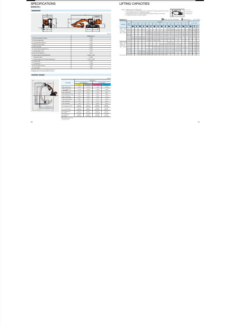
LIFTING CAPACITIESSPECIFICATIONS
0 21
WORKING RANGES
Arm length
ZX520LCH-3
6.3 m BE-boom 7.0 m H-boom
2.5 m BE-arm 2.9 m BE-arm 2.9 m BE-arm 3.4 m H-arm
A Max. digging reach 10 460 10 750 11 330 12 060
A’ Max. digging reach(on ground)
10 190 10 490 11 080 11 820
B Max. digging depth 5 720 6 050 7 130 7 690
B’ Max. digging depth (8' level) 5 540 5 890 6 920 7 550
C Max. cutting height 10 730 10 870 10 240 11 130
D Max. dumping height 7 390 7 520 7 170 7 730
E Min. swing radius 4 090 3 930 5 020 4 840
F Max. vertical wall 4 180 4 570 4 200 7 030
Bucket digging force* ISO287 kN
(29 300 kgf )287 kN
(29 300 kgf )287 kN
(29 300 kgf )288 kN
(29 400 kgf )
Arm crowd force* ISO293 kN
(29 900 kgf )256 kN
(26 100 kgf )256 kN
(26 100 kgf )218 kN
(22 200 kgf )
Bucket digging force*SAE : PCSA
258 kN(26 300 kgf )
258 kN(26 300 kgf )
258 kN(26 300 kgf )
250 kN(25 500 kgf )
Arm crowd force *SAE : PCSA
286 kN(29 200 kgf )
249 kN(25 400 kgf )
249 kN(25 400 kgf )
209 kN(21 300 kgf )
012345678910111213141516171813
12
11
10
9
8
7
6
5
4
3
2
1
0
1
2
3
4
5
6
7
8
9
10
11
12
13
meter
meter
Ground
Line
C
D
E
FB B' 8'
A
A'
Rating over-side or 360 degrees Rating over-front Unit: 1 000 kg
Conditions
Load
pointheight
Load radius
At max. reach3 m 4 m 5 m 6 m 7 m 8 m 9 m 10 m
meter
H-Boom 7.00 m
H-Arm 3.40 mRock-bucketSAE,PCSA: 2.10 m3
Shoe 600 mm
8 m *7.9 *7.9 *3.7 *3.7 10.3
6 m *9.1 *9.1 7.9 *8.7 *3.7 *3.7 11.1
4 m *16.5 *16.5 *13.5 *13.5 *11.6 *11.6 9.4 *10.3 7.6 *9.4 6.2 *8.5 *3.8 *3.8 11.6
2 m 18.3 *18.9 13.9 *16.6 10.9 *13.7 8.8 *11.7 7.2 *10.3 6.0 9.2 *4.2 *4.2 11.6
0 (Ground) 17.5 *17.7 13.2 *18.0 10.4 *14.9 8.4 *12.6 6.9 10.7 5.8 9.0 4.8 *4.8 11.2
–2 m *10.1 *10.1 *16.9 *16.9 17.5 *20.8 13.0 *17.5 10.1 *14.7 8.2 *12.5 6.8 10.6 5.5 *5.9 10.3
–4 m *21.7 *21.7 *20.3 *20.3 *17.7 *17.7 13.1 *15.2 10.2 *12.9 8.3 *10.8
–6 m *11.7 *11.7 *9.9 *9.9
H-Boom 7.00 m
BE-Arm 2.90 mRock-bucketSAE,PCSA: 2.30 m3
Shoe 600 mm
7 m *9.3 *9.3 *5.6 *5.6 10.0
6 m *10.2 *10.2 *9.5 *9.5 7.7 *8.3 *5.7 *5.7 10.4
4 m *17.8 *17.8 *14.2 *14.2 11.5 *12.1 9.1 *10.7 7.4 *9.7 5.2 *6.0 10.9
2 m 13.4 *17.0 10.6 *13.9 8.6 *11.9 7.0 *10.5 5.8 9.1 5.0 *6.7 10.9
0 (Ground) 17.3 *18.1 12.9 *17.8 10.1 *14.8 8.2 *12.6 6.8 10.6 5.3 *7.9 10.5
–2 m *20.2 *20.2 17.4 *19.5 12.8 *16.8 10.0 *14.3 8.1 *12.2 6.7 *10.3 6.2 *6.5 9.5
–4 m *17.7 *17.7 *16.0 *16.0 13.1 *14.0 10.2 *11.9 8.3 *9.8
–5 m *14.4 *14.4 *13.2 *13.2 *11.5 *11.5 *9.5 *9.5
A
B
C
DIMENSIONS
ZX520LCH-3 *2
A Dist ance between tumblers 4 250
B Undercarriage length 5 330
C Counterweight clearance 1 435
D Rear-end swing radius 3 645
D’ Rear-end length 3 560
E Overall width of upperstructure 3 530
F Overall height of cab 3 520
G Min. ground clearance 810
H Track gauge: Extenced/Retracted 2 920 / 2 420
I Track shoe width G 600
J Undercarriage width: Extended/Retracted 3 520 / 3 020
K Overall width 3 860
L Overall length 11 890
M Overall height of boom 3 500
N Track height 1 290
X520LCH-3
A: Load radius
B: Load point height
C: Lifting capacity
Unit:mm
Unit:mm
Excluding track shoe lug. G: Double grouser shoeEquipped with 7.0 m H-boom and 3.4 m H-arm
Excluding track shoe lug* At power boost
Notes: 1. Ratings are based on SAE J1097.
2. Lifting capacity of the ZAXIS Series does not exceed 75 % of tipping load with the machine
on rm, level ground or 87 % full hydraulic capacity.
3. The load point is a hook (not standard equipment) located on the back of the bucket.
4. *Indicates load limited by hydraulic capacity.
ZX520LCH-3

7/28/2019 KS-EN030
http://slidepdf.com/reader/full/ks-en030 12/17
EQUIPMENT
2 23
X520LCH-3
STANDARD EQUIPMENT Standard equipment may vary by country, so please consult your Hitachi dealer for details.
ENGINE
H/P mode control
P mode control
E mode control
50 A alternator
Dry-type air double lter with
evacuator valve (with air lter
restriction switch for monitor)
Cartridge-type engine oil lter
Cartridge-type fuel lter
Fuel pre-lter
Radiator, oil cooler and intercooler
with dust protective net
Radiator reserve tank
Fan guard
solation-mounted engine
Auto-idle system
CAB
- H/R cab
- OPG top guard tted Level II
(ISO10262) compliant cab
- All-weather sound suppressed
steel cab
- Laminated straight and xed glass
front window
- Left side window can be opened
- 6 uid-lled elastic mounts
- Intermittent windshield wipers
- Front window washer
- Adjustable reclining suspension
seat with adjustable armrests
- Footrest
- Electric double horn
- AM-FM radio with digital clock
- Auto-idle selector
- Retractable Seat belt
- Drink holder
- Cigarette lighter
- Ashtray
- Storage box
- Glove compartment
- Floor mat
- Short wrist control levers
- Pilot control shut-off lever
- Auto control air conditioner
- Pilot control shut-off lever
- Engine shut-off switch
MONITOR SYSTEM
- Display of meters: water
temperature, hour, fuel rate, clock
- Other displays: work mode, auto-
idle, glow, rear view monitor (when
optional rear view camera is
equipped), operating conditions,
etc
- Alarms: overheat, engine warning,
engine oil pressure, alternator,
minimum fuel level, hydraulic lter
restriction, air lter restriction, work
mode, overload, etc
- Alarm buzzers: overheat, engine oil
pressure, overload
UNDERCARRIAGE
- Travel parking brake
- Travel motor covers
- Hydraulic track adjuster
- Idler track guard
- Bolt-on sprocket
- Upper and lower rollers
- Reinforced track links with pin seals
- Full track guard
- 600 mm double grouser shoes
OPTIONAL EQUIPMENT Optional equipment may vary by country, so please consult your Hitachi dealer for details.
HYDRAULIC SYSTEM
Work mode selectorEngine speed sensing system
E-P control system
Power boost
Auto power lift
Boom mode selector system
Shockless valve in pilot circuit
Control valve with main relief valve
Extra port for control valve
Suction lter
Full-ow lter
Pilot lter
Drain lter
Quick warm-up system for pilot
circuit
LIGHTS
- 2 working lights
- 2 cab lights
UPPERSTRUCTURE
- 4.5 mm thickness Undercover
- 9 820 kg counterweight
- Fuel level oat
- 170 Ah batteries
- Hydraulic oil level gauge
- Tool box
- Utility space
- Rear view mirror (right & left side)
- Swing parking brake
- Ladder
FRONT ATTACHMENTS
- Flanged pin
- Monolithically cast bucket link A
- Centralized lubrication systen
- Dirt seal on all bucket pins
- 7.0 m H-boom and 3.4 m H-arm
- Damage prevention plate and
square bars
- 1.90 m3
(SAE, PCSA heaped) rock bucket (with dual type side shrouds)
MISCELLANEOUS
- Standard tool kit
- Lockable machine covers
- Lockable fuel relling cap
- Skid-resistant tapes, plates and
handrails
- Travel direction mark on track
frame
- Onboad information controller
- Theft deterrent system
- Hose rupture valves
- Electric fuel relling pump with
autostop
- Swing motion alarm device with
lamps
- Travel motion alarm device
- Biodegradable oil
- Extinguisher
- Pre cleaner
- Cab front step
- Auto-grease lubricator
- Electric grease gun
- Right side walk
- Rain guard for cab
- Attachment basic piping
- Accessories for breaker
- Accessories for breaker & crusher
- Accessories for 2 speed selector
- Sun visor
- 12 V power source
- Additional fuse box
- Overload alarm
- Rear view camera
- Front glass lower guard
- Front glass upper guard
- 6.3 m BE-boom
- 2.5 m BE-arm
- 2.9 m BE-arm

7/28/2019 KS-EN030
http://slidepdf.com/reader/full/ks-en030 13/17
SPECIFICATIONS
4 25
X500LC-3
ZX500LC-3
Capacity Width
No. ofteeth
Weight
Recommendation
ZX500LC-3
SAE, PCSA heapedCECE
heaped
Without
side cutters
With
side cutters
6.3 m BE-boom 7.0 m boom 8.2 m boom
2.5 m
BE-arm
2.9 m
BE-arm
2.9 m
arm
3.4 m
arm
3.9 m
arm
4.9 m
arm
4.9 m
arm
1.15 m3 1.00 m3 1 100 mm 1 210 mm 5 1 070 kg X X X X X
1.40 m3 1.20 m3 1 280 mm 1 410 mm 5 1 170 kg X X X X X —
1.60 m3 1.40 m3 1 220 mm 1 360 mm 5 1 480 kg — — X X
1.90 m3 1.70 m3 1 400 mm 1 540 mm 5 1 590 kg — — X X
2.10 m3 1.80 m3 1 490 mm 1 630 mm 5 1 650 kg — — X X
2.30 m3 2.00 m3 1 520 mm 1 660 mm 5 1 800 kg — X X
2.50 m3 2.20 m3 1 630 mm 1 770 mm 5 1 870 kg — — — X X
2.65 m3 2.30 m3 1 720 mm 1 860 mm 5 1 930 kg — — — X X
Applicable shoe type
600 mm Triple grouser
750 mm Triple grouser
900 mm Triple grouser
Suitable for materials with desity of 1 600 kg/m3 or less
Suitable for materials with desity of 1 800 kg/m3 or less
— Not applicable
X Can't installed
Model ...........................
Type ............................
Aspiration ....................
No. of cylinders ...........
Rated power
ISO 9249, net ........
(Without Fan)
EEC 80/1269, net ..
(Without Fan)
SAE J1349, net .....
(Without Fan)
Maximum torque .........
Piston displacement ....
Bore and stroke...........
Batteries......................
Main pumps ................
Maximum oil ow...
Pilot pump...................
Maximum oil ow...
Travel ..........................
Swing ..........................
mplement circuit .........
Swing circuit................
Travel circuit ................
Pilot circuit ..................
Power boost ...............
Quantity Bore Rod diameter
Boom 2 170 mm 115 mm
Arm 1 190 mm 130 mm
Bucket 1 170 mm 120 mm
mplement levers .........
Travel levers with
pedals .........................
Swing speed ...............
Upper rollers................
Lower rollers................
Track shoes .................
Track guard .................
Travel speeds ...............
Maximum traction force ....
Gradeability....................
S ho e ty pe S ho e wi dt h O pe ra ti ng w ei gh t G ro un d pre ss ur e
Triple
grouser
600 mm 49 500 kg 88 kPa (0.89 kgf/cm2)
750 mm 50 300 kg 71 kPa (0.72 kgf/cm2)
900 mm 51 100 kg 60 kPa (0.61 kgf/cm2)
Fuel tank ...................................................................................
Engine coolant ..........................................................................
Engine oil ..................................................................................
Swing device (each side) ...........................................................
Travel device (each side) ............................................................
Hydraulic system .......................................................................
Hydraulic oil tank .......................................................................
Isuzu AH-6WG1XYSA-01
4-cycle water-cooled, direct injection
Turbocharged
6
H/P mode :
260 kW (349 HP) at 1 800 min-1(rpm)
H/P mode :
260 kW (349 HP) at 1 800 min-1(rpm)
H/P mode :
260 kW (349 HP) at 1 800 min-1(rpm)
1 580 Nm (161 kgf m) at 1 50 0 min-1 (rpm)
15.681 L
147 mm x 154 mm
2 x 12 V / 170 AH
2 variable displacement axial piston pumps
2 x 360 L/min
1 gear pump
30 L/min
HYDRAULIC SYSTEM
Work mode selector
ydraulic Motors
2 axial piston motors with parking brake
2 axial piston motors
elief Valve Settings
31.9 MPa (325 kgf/cm2)
28.4 MPa (290 kgf/cm2)
34.3 MPa (350 kgf/cm2)
3.9 MPa (40 kgf/cm2)
ydraulic Cylinders
gh-strength piston rods and tubes. Cylinder cushion mechanisms
ovided in boom and arm cylinders to absorb shock at stroke ends.
imensions
ydraulic Filters
ydraulic circuits use high-quality hydraulic lters. A suction lter is
corporated in the suction line, and full-ow lters in the return line and
wing/travel motor drain lines.
CONTROLS
2
2
lot controls. Hitachi's original shockless valve.
ENGINE
Engine speed sensing system
General purpose mode / Attachment mode
34.3 MPa (350 kgf/cm2)
UPPERSTRUCTURE
9.0 min-1 (rpm)
Revolving FrameWelded sturdy box construction, using heavy-gauge steel plates for
ruggedness. D-section frame for resistance to deformation.
Operator's CabIndependent spacious cab, 1 005 mm wide by 1 675 mm high,
conforming to ISO* Level I Standards. Reinforced g lass windows on 4
sides for visibility. Openable front windows (upper and lower). Reclining
seat with armrests; adjustable with or without control levers.
* International Standardization Organization
Swing Device Axial piston motor with planetary reduction gear is bathed in oil. Swing
circle is single-row, shear-type ball bearing with inductionhardened
internal gear. Internal gear and pinion gear are immersed in lubricant.
Swing parking brake is spring-set/hydraulic-released disc type.
UNDERCARRIAGE
Tracks
Tractor-type undercarriage. Welded track frame using selected materials.Side frame bolted to track frame. Lubricated track rollers, idlers, and
sprockets with oating seals.
Track shoes with triple grousers made of induction-hardened rolled alloy.
Heat-treated connecting pins with dirt seals. Hydraulic (grease) track
adjusters with shock-absorbing recoil springs.
Numbers of Rollers and Shoes on Each Side
3
8
49
2
Travel DeviceEach track driven by axial piston motor through reduction gear for
counterrotation of the tracks. Sprockets are replace able. Parking brake
is spring-set/hydraulic-released disc type.
Automatic transmission system: High-Low.
High : 0 to 4.0 km/h
Low : 0 to 2.9 km/h
415 kN (42 300 kgf)
70 % (35 degree) continuous
WEIGHTS AND GROUND PRESSURE
Equipped with 7.0 m boom, 3.4 m arm, and 2.10 m3 bucket
(SAE, PCSA heaped).
BACKHOE ATTACHMENTS
Boom and arms are of a ll-welded, box-section design. A number of
booms and arms are available. Bucket is of all-welded, high-strength
steel structure.
SERVICE REFILL CAPACITIES
725.0 L
55.0 L
57.0 L
6.5 L
11.0 L
560.0 L
330.0 L
Backhoe Buckets
Note: Depending on the jobsites conditions, 750 mm grouser shoe and 900 mm grousershoe may not be recommended for rock, hard surface or forestry application.

7/28/2019 KS-EN030
http://slidepdf.com/reader/full/ks-en030 14/17
SPECIFICATIONS LIFTING CAPACITIES
6 27
Arm length
ZX500LC-3
6.3 m BE-boom 7.0 m boom 8.2 m boom
2.5 mBE-arm 2.9 mBE-arm 2.9 m arm 3.4 m arm 3.9 m arm 4.9 m arm 4.9 m arm
A Max. digging reach 10 570 10 860 11 400 12 060 12 490 13 340 14 510
A’ Max. digging reach (on ground) 10 300 10 600 11 150 11 820 12 270 13 130 14 320
B Max. digging depth 5 820 6 160 7 200 7 690 8 200 9 030 10 150
B’ Max. digging depth (8' level) 5 650 6 000 7 000 7 550 8 070 8 920 10 040
C Max. cutting height 10 820 10 960 10 330 11 130 11 240 11 810 12 310
D Max. dumping height 7 290 7 410 7 100 7 730 7 840 8 750 9 290
E Min. swing radius 4 070 3 930 5 020 4 840 4 810 4 850 5 870
F Max. vertical wall 4 550 4 950 5 190 6 510 6 900 8 340 9 330
Bucket digging force
ISO*
277 kN
(28 300 kgf)
277 kN
(28 300 kgf)
277 kN
(28 300 kgf)
278 kN
(28 400 kgf)
278 kN
(28 400 kgf)
231 kN
(23 600 kgf)
231 kN
(23 600 kgf)
Arm crowd force ISO*286 kN
(29 200 kgf)
249 kN
(25 400 kgf)
252 kN
(25 700 kgf)
216 kN
(22 000 kgf)
195 kN
(19 900 kgf)
172 kN
(17 600 kgf)
172 kN
(17 600 kgf)
Bucket digging force*
SAE : PCSA
250 kN
(25 500 kgf)
250 kN
(25 500 kgf)
247 kN
(25 200 kgf)
249 kN
(25 400 kgf)
249 kN
(25 400 kgf)
207 kN
(21 100 kgf)
207 kN
(21 100 kgf)
Arm crowd force*SAE : PCSA
277 kN(28 300 kgf)
242 kN(24 700 kgf)
245 kN(25 000 kgf)
209 kN(21 300 kgf)
190 kN(19 400 kgf)
170 kN(17 300 kgf)
170 kN(17 300 kgf)
WORKING RANGES
DIMENSIONS
ZX500LC-3 *2
A Distance between tumblers 4 250
B Undercarriage length 5 330
C Counterweight clearance 1 435
D Rear-end swing radius 3 645
D’ Rear-end length 3 560
E Overall width of upperstructure 3 530
F Overall height of cab 3 410
G Min. ground clearance 810
H Track gauge: Extenced/Retracted 2 920 / 2 420
I Track shoe width G 600 / G 750 / G 900
J Undercarriage width
G 600 3 520 / 3 020
Extended/Retracted G 750 3 670 / 3 170
G 900 3 820 / 3 590
K Overall width 3 860
L Overall length 11 890
M Overall height of boom 3 500
N Track height 1 290
012345678910111213141516171813
12
11
10
9
8
7
6
5
4
3
2
1
0
1
2
3
4
5
6
7
8
9
10
11
12
13
meter
meter
C
D
E
FB B' 8'
A
A'
Ground
Line
X500LC-3
Rating over-side or 360 degrees Rating over-front Unit: 1 000 kg
Conditions
Load
pointheight
Load radius
At max. reach2 m 3 m 4 m 5 m 6 m 7 m 8 m 9 m 10 m
meter
Boom 7.00 m
Arm 3.40 mBucketSAE,PCSA: 2.10 m3
Shoe 600 mm
8 m *8.1 *8.1 *4.2 *4.2 10.1
6 m *9.7 *9.7 8.3 *9.3 *4.2 *4.2 11.0
4 m *16.9 *16.9 *13.9 *13.9 12.1 *12.1 9.7 *10.9 8.0 *10.0 6.6 *8.7 *4.3 *4.3 11.5
2 m 18.7 *21.8 14.3 *17.1 11.3 *14.2 9.2 *12.3 7.6 *10.9 6.4 9.6 *4.7 *4.7 11.5
0 (Ground) 17.9 *18.8 13.5 *18.6 10.7 *15.5 8.8 *13.2 7.3 11.0 6.2 9.4 5.2 *5.3 11.1
–2 m *10.8 *10.8 *17.4 *17.4 17.8 *21.7 13.3 *18.2 10.5 *15.4 8.6 13.1 7.2 10.9 5.9 *6.5 10.3
–4 m *24.1 *24.1 *21.5 *21.5 18.1 *18 .6 13.5 *16.0 10.6 *13.7 8.7 *11.6 7.7 *8.1 8.8
–6 m * 12 .8 * 12 .8 * 10 .9 * 10 .9 * 8. 5 * 8. 5
Boom 7.00 m
Arm 3.90 mBucketSAE,PCSA: 1.90 m3
Shoe 600 mm
8 m *4.7 *4.7 *3.5 *3.5 10.6
6 m *8.9 *8.9 8.3 *8.6 *5.6 *5.6 *3.5 *3.5 11.5
4 m *12.8 *12.8 *11.3 *11.3 9.8 *10.2 8.0 *9.4 6.6 *8.8 *3.6 *3.6 11.9
2 m 18.9 *20.5 14.3 *16.2 11.3 *13.5 9.2 *11.7 7.6 *10.5 6.3 9.5 *3.9 *3.9 11.9
0 (Ground) *8.4 *8.4 17.8 *22.2 13.4 *18.1 10.6 *15.1 8.7 *12.9 7.2 10.9 6.1 9.2 *4.5 *4.5 11.6
–2 m *8.2 *8.2 *11.3 *11.3 *17.1 *17.1 17.5 *22.0 13.1 *18.2 10.3 *15.3 8.4 12.9 7.0 10.7 5.9 9.1 5.4 *5.4 10.8
–4 m *22.1 *22.1 *23.1 *23.1 17.7 *19.5 13.2 *16.5 10.3 *14.1 8.4 *12.0 7.1 *10.0 6.8 *7.3 9.4
–6 m *16 .7 *16 .7 *14 .5 *14 .5 *12 .4 *12 .4 *10 .3 *10 .3
A
B
C
A: Load radius
B: Load point height
C: Lifting capacity
Unit:mm
Unit:mm
Excluding track shoe lug. *2 Equipped with 7.0 m boom and 3.4 m arm
Excluding track shoe lug* At power boost
Notes: 1. Ratings are based on SAE J1097.
2. Lifting capacity of the ZAXIS Series does not exceed 75 % of tipping load with the machine
on rm, level ground or 87 % full hydraulic capacity.
3. The load point is a hook (not standard equipment) located on the back of the bucket.
4. *Indicates load limited by hydraulic capacity.
ZX500LC-3

7/28/2019 KS-EN030
http://slidepdf.com/reader/full/ks-en030 15/17
EQUIPMENT
8 29
X500LC-3
STANDARD EQUIPMENT Standard equipment may vary by country, so please consult your Hitachi dealer for details.
ENGINE
H/P mode control
P mode control
E mode control
50 A alternator
Dry-type air double lter with
evacuator valve (with air lter
restriction switch for monitor)
Cartridge-type engine oil lter
Cartridge-type fuel lter
Fuel pre-lter
Radiator, oil cooler and intercooler
with dust protective net
Radiator reserve tank
Fan guard
solation-mounted engine
Auto-idle system
CAB
- CRES II cab
- OPG top guard tted Level I
(ISO10262) compliant cab
- All-weather sound suppressed
steel cab
- Tinted (green color) glass windows
- 6 uid-lled elastic mounts
- Openable windows ; upper and
lower front, and left side
- Intermittent windshield wipers
- Front window washer
- Adjustable reclining suspension
seat with adjustable armrests
- Footrest
- Electric double horn
- AM-FM radio with digital clock
- Auto-idle selector
- Retractable Seat belt
- Drink holder
- Cigarette lighter
- Ashtray
- Storage box
- Glove compartment
- Floor mat
- Short wrist control levers
- Pilot control shut-off lever
- Auto control air conditioner
- Pilot control shut-off lever
- Engine shut-off switch
MONITOR SYSTEM
- Display of meters: water
temperature, hour, fuel rate, clock
- Other displays: work mode, auto-
idle, glow, rear view monitor (when
optional rear view camera is
equipped), operating conditions,
etc
- Alarms: overheat, engine warning,
engine oil pressure, alternator,
minimum fuel level, hydraulic lter
restriction, air lter restriction, work
mode, overload, etc
- Alarm buzzers: overheat, engine oil
pressure, overload
UNDERCARRIAGE
- Travel parking brake
- Travel motor covers
- 2 track guard (each side) and
hydraulic track adjuster
- Idler track guard
- Bolt-on sprocket
- Upper and lower rollers
- Reinforced track links with pin seals
- 600 mm triple grouser shoes
OPTIONAL EQUIPMENT Optional equipment may vary by country, so please consult your Hitachi dealer for details.
HYDRAULIC SYSTEM
Work mode selectorEngine speed sensing system
E-P control system
Power boost
Auto power lift
Boom mode selector system
Shockless valve in pilot circuit
Control valve with main relief valve
Extra port for control valve
Suction lter
Full-ow lter
Pilot lter
Drain lter
Quick warm-up system for pilot
circuit
LIGHTS
- 2 working lights
UPPERSTRUCTURE
- Undercover
- 9 820 kg counterweight
- Fuel level oat
- 170 Ah batteries
- Hydraulic oil level gauge
- Tool box
- Utility space
- Rear view mirror (right & left side)
- Swing parking brake
- Ladder
FRONT ATTACHMENTS
- Flanged pin
- Monolithically cast bucket link A
- Centralized lubrication systen
- Dust seal on all bucket pins
- 7.0 m boom and 3.4 m arm
- 2.10 m3 (SAE, PCSA heaped)
bucket
MISCELLANEOUS
- Standard tool kit
- Lockable machine covers
- Lockable fuel relling cap
- Skid-resistant tapes, plates and
handrails
- Travel direction mark on track
frame
- Onboad information controller
- Theft deterrent system
- H/R cab : OPG top guard tted
Level II (ISO10262) compliant cab
(with 2 cab lights)
- Hose rupture valves
- Electric fuel relling pump with
autostop
- Swing motion alarm device with
lamps
- Travel motion alarm device
- Biodegradable oil
- Extinguisher
- Pre cleaner
- Cab front step
- 2 cab lights (for CERS II cab)
- Auto-grease lubricator
- Electric grease gun
- Right side walk
- Rain guard for cab
- Attachment basic piping
- Accessories for 2 speed selector
- 12 V power source
- Additional fuse box
- Overload alarm
- Rear view camera
- Front glass lower guard
- Front glass upper guard
- Full track guard
- 750 mm Triple grouser shoe
- 900 mm Triple grouser shoe
- 6.3 m BE-boom
- 2.5 m BE-arm
- 2.9 m BE-arm
- 2.9 m arm
- 3.9 m arm
- 4.9 m arm
7/28/2019 KS-EN030
http://slidepdf.com/reader/full/ks-en030 16/17
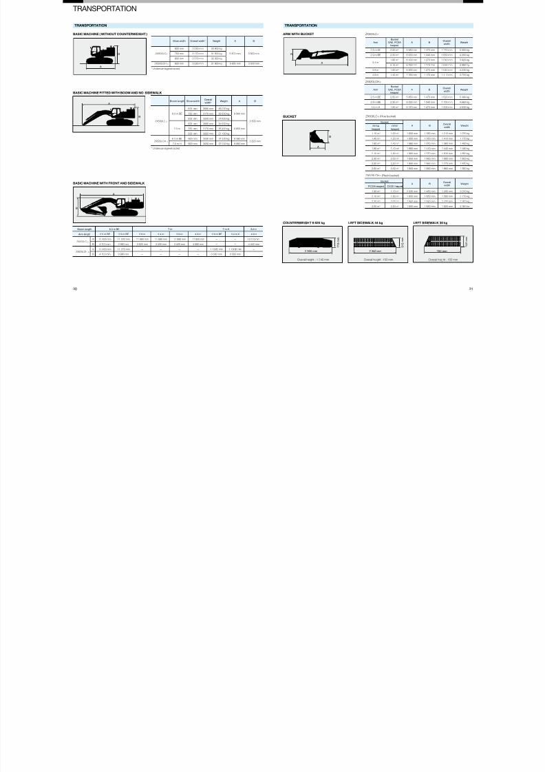
TRANSPORTATION
0 31
A
B
A
B
ASIC MACHINE WITH FRONT AND SIDEWALK
Boom length 6.3 m BE 7 m 7 m H 8.2 m
Arm length 2.5 m BE 2.9 m BE 2.9 m 3.4 m 3.9 m 4.9 m 2.9 m BE 3.4 m H 4.9 m
ZX500LC-3
A 11 400 mm 11 220 mm 11 980 mm 11 890 mm 11 890 mm 11 800 mm — — 13 110 mm
B 4 100 mm 3 980 mm 3 620 mm 3 500 mm 3 500 mm 4 680 mm — — 4 450 mm
ZX520LCH -3
A 11 400 mm 11 270 mm — — — — 1 1 9 80 mm 1 1 8 90 mm —
B 4 100 mm 3 980 mm — — — — 3 500 mm 3 500 mm —
Arm
Bucket
SAE, PCSA
heaped
A BOverall
widthWeight
2.5 m BE 2.50 m3 5 650 mm 1 470 mm 1 770 mm 5 000 kg
2.9 m BE 2.30 m3 6 030 mm 1 340 mm 1 660 mm 4 200 kg
3.4 m1.90 m3 6 430 mm 1 270 mm 1 540 mm 3 920 kg
2.10 m3 6 430 mm 1 270 mm 1 630 mm 3 980 kg
3.9 m 1.90 m3 6 930 mm 1 270 mm 1 540 mm 4 230 kg
4.9 m 1.40 m3 7 760 mm 1 170 mm 1 410 mm 3 720 kg
Arm
Bucket
SAE, PCSA
heaped
A BOverall
widthWeight
2.5 m BE 2.50 m3 5 650 mm 1 470 mm 1 820 mm 5 490 kg
2.9 m BE 2.30 m3 6 030 mm 1 340 mm 1 700 mm 4 660 kg
3.4 m H 1.90 m3 6 370 mm 1 470 mm 1 500 mm 4 630 kg
A
B
A
B
ZX500LC-3
ZX520LCH-3
Bucket
A BOverall
widthWeightPCSA
heaped
CECE
heaped
1.15 m3 1.00 m3 1 800 mm 1 350 mm 1 210 mm 1 070 kg
1.40 m3 1.20 m3 1 800 mm 1 350 mm 1 410 mm 1 170 kg
1.60 m3 1.40 m3 1 960 mm 1 570 mm 1 360 mm 1 480 kg
1.90 m3 1.70 m3 1 960 mm 1 570 mm 1 540 mm 1 590 kg
2.10 m3 1.80 m3 1 960 mm 1 570 mm 1 630 mm 1 650 kg
2.30 m3 2.00 m3 1 950 mm 1 660 mm 1 660 mm 1 800 kg
2.50 m3 2.20 m3 1 950 mm 1 660 mm 1 770 mm 1 870 kg
2.65 m3 2.30 m3 1 950 mm 1 660 mm 1 860 mm 1 930 kg
Bucket A B
Overall
widthWeight
PCSA heaped CECE heaped
1.90 m3 1.70 m3 2 030 mm 1 480 mm 1 500 mm 2 070 kg
2.10 m3 1.80 m3 1 950 mm 1 650 mm 1 580 mm 2 170 kg
2.30 m3 2.00 m3 1 950 mm 1 650 mm 1 700 mm 2 260 kg
2.50 m3 2.20 m3 1 950 mm 1 650 mm 1 820 mm 2 360 kg
A
B
2 960 mm
7 1 0 m m
2 340 mm
5 1 5 m m
700 mm
5 1 5 m m
COUNTERWEIGHT 9 820 kg LEFT SIDEWALK 44 kg LEFT SIDEWALK 30 kg
ZX520LCH-3 (Rock bucket)
ZX500LC-3 (Hoe bucket)
TRANSPORTATIONTRANSPORTATION
ASIC MACHINE ( WITHOUT COUNTERWEIGHT )
ASIC MACHINE FITTED WITH BOOM AND NO SIDEWALK
ARM WITH BUCKET
BUCKET
Shoe width Overall width* Weight A B
ZX500LC-3
600 mm 3 060 mm 30 800 kg
5 400 mm 3 500 mm750 mm 3 170 mm 31 500 kg
900 mm 3 320 mm 32 300 kg
ZX520LCH -3 600 mm 3 060 mm 31 900 kg 5 620 mm 3 520 mm
Boom length Shoe widthOverall
width*Weight A B
ZX500LC-3
6.3 m BE
600 mm 3060 mm 36 000 kg
9 060 mm
3 500 mm
750 mm 3170 mm 36 800 kg
900 mm 3320 mm 37 600 kg
7.0 m
600 mm 3060 mm 35 600 kg
9 850 mm750 mm 3170 mm 36 400 kg
900 mm 3320 mm 37 100 kg
ZX520LCH -3
6.3 m BE 600 mm 3060 mm 37 200 kg 9 060 mm3 520 mm
7.0 m H 600 mm 3060 mm 37 000 kg 9 850 mm
* Undercarriage retracted
* Undercarriage retracted
Overall height : 1 340 mm Overall height : 150 mm Overall height : 150 mm

7/28/2019 KS-EN030
http://slidepdf.com/reader/full/ks-en030 17/17
Hitachi Construction Machinery
These specications are subject to change without notice.
Illustrations and photos show the standard models, and may or may not include optional equipment,
accessories, and all standard equipment with some differences in color and features.
Before use, read and understand the Operator's Manual for proper operation.