KOBELCO WELDING TODAY - 神戸製鋼所 · KOBELCO WELDING TODAY 3 Process piping conveys fluid to...
12
Transcript of KOBELCO WELDING TODAY - 神戸製鋼所 · KOBELCO WELDING TODAY 3 Process piping conveys fluid to...
1
KO
BELC
O W
EL
DIN
G T
OD
AY
Products Spotlight
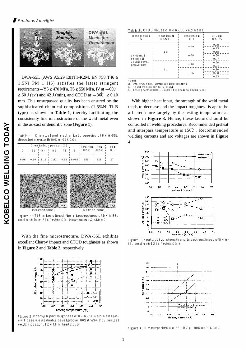
DWA-55L (AWS A5.29 E81T1-K2M, EN 758 T46 61.5Ni PM 1 H5) satisfies the latest stringentrequirements-YS ≥ 470 MPa, TS ≥ 550 MPa, IV at -60℃≥ 60 J (av.) and 42 J (min), and CTOD at -36℃ ≥ 0.10mm. This unsurpassed quality has been ensured by thesophisticated chemical compositions (1.5%Ni-Ti-Btype) as shown in Table 1, thereby facilitating theconsistently fine microstructure of the weld metal evenin the as-cast or dendritic zone (Figure 1).
With higher heat input, the strength of the weld metaltends to decrease and the impact toughness is apt to beaffected more largely by the testing temperature asshown in Figure 3. Hence, these factors should becontrolled in welding procedures. Recommended preheatand interpass temperature is 150℃. Recommendedwelding currents and arc voltages are shown in Figure4.
With the fine microstructure, DWA-55L exhibitsexcellent Charpy impact and CTOD toughness as shownin Figure 2 and Table 2, respectively.
Figure 2. Charpy impact toughness of DWA-55L weld metal (60-mmT base metal, double bevel groove, 80%Ar-20%CO2, verticalwelding position, 1.8-kJ/mm heat input)
Figure 1. Ti-B micro-alloyed fine microstructures of DWA-55Lweld metal with 80%Ar-20%CO2 (Heat input: 1.7 kJ/mm)
0.2%PS�(MPa)
TS�(MPa)
EL�(%)
Chemical composition (%)
C
0.06 0.30 1.15 1.41 0.06 0.003 558 626 27
Si Mn Ni Ti B
Table 1. Chemical and mechanical properties of DWA-55Ldeposited metal with 80%Ar-20%CO2
Base metal �(2)�
SM490A, �60 mmT,�Double bevel groove joint
Heat input�(kJ/mm)
Test temp.� (℃)
CTOD�(mm) (3)�
1.8
-40
-36
-40
-36
0.380.790.430.880.370.560.840.900.530.93
1.1
Note:�(1) 80%Ar-20%CO2, vertical welding position�(2) Rolled steel as per JIS G 3106�(3) Testing method: BSI BS7448-91 (Specimen size: W = B)
Table 2. CTOD values of DWA-55L weld metal (1)
(As-cast zone) (Refined zone)
Figure 3. Heat input vs. strength and impact toughness of DWA-55L weld metal (80%Ar-20%CO2)
Figure 4. A-V range for DWA-55L (1.2φ, 80%Ar-20%CO2)
Stormy,� Freezing� Seas...��
Tougher Materials...
DWA-55L Meets the Requirement
Preface
2
KO
BELC
O W
EL
DIN
G T
OD
AY
Contents
P1Products Spotlight:
DWA-55Lfor better CTOD
P3-7Technical Highlight:
GTAW of stainless steel piping
P8Technical Terms Explanation:
CTOD
P9Bulletin:
Fighting against...
P10Bulletin:
Beijing Essen Fair
Kobelco Welding of Europe B.V. (KWE) is situated in the
southern part of the Netherlands. At this moment KWE has a
total of 42 employees, most of whom are Dutch. During a
working-day, there are 3 shifts that make use of the
company canteen.
During lunchtime, everybody takes out their own home-
made sandwiches, because KWE is too small to have a kitchen
that can serve hot meals. However, employees can order
sandwiches at a deli-shop. The most popular sandwich is the
French bread with vegetables, ham and cheese.
In the canteen are two cold drink machines, one candy
machine and one coffee machine. Every morning we receive
the newspaper, which is read inside-out by almost everybody.
Reported by
L. Gorissen and T. Bronneberg-Wirtz
KWE
Canteen in KWE
A Happy New Year to Dear KWT Readers!!
In Japan we celebrate the New Year from the first to seventh of January, especially forthe first three days of the year. During the days from January 1 to 7, which we call“Matsu-no-Uchi”(literally,“within the days of Matsu”), we used to use pine tree branches
(the“Matsu”was thought to be a holy tree) to decorate the entrances of houses,companies and public buildings, hoping health, happiness and prosperity. Nowadays,however, I seldom see this kind of decoration in my town, though it may be different fromtown to town. I regret that many historical customs or traditions have been lost. How aboutin your countries? Anyhow I hope this year will be fruitful for all of the readers ofKobelco Welding Today.
It is also regretful to me that the supply and demand balance for welding consumableswill not noticeably improve due to the shortage of raw materials this year. Even withinKobe Steel, the tight supply of wire rods for welding consumables makes it tough for thecompany to respond to our increasing demands. As the consumption of weldingconsumables increases at the sites of most of our customers, we find we cannot fulfill alltheir demands. Furthermore, our customers experience supply-demand imbalances notonly for welding consumables but also for steel plates.
I think these circumstances will continue and even deteriorate further in the near future.What we can do is to do our best to get more raw materials to supply more weldingconsumables to respond your increasing demands. To ensure better supply of rawmaterials, we reluctantly have had to accept some price increases. This is another big issuefor us. However, I would like everybody to know that although the situation is difficult, Iwill make my best effort to maximize our supply for your demands. I am also hoping for aslow but certain favorable turn in the market situation in the near future.
Masakazu TojoGeneral Manager
International Operations Dept.Welding Company
Kobe Steel, Ltd.
KO
BELC
O W
EL
DIN
G T
OD
AY
3
Process piping conveys fluid to and from a plant’svarious pieces of equipment such as furnaces, reactors,heat exchangers, distillation towers, boilers and turbines.It also connects one process unit with another, and mayat times be assembled in long straight runs. Stainlesssteels-mainly austenitic types-are preferred for pipingused at high or cryogenic temperatures, or in highlycorrosive environments. The main grades of stainlesssteels for the process piping are shown in Table 1.
Technical Highlight
ASTM�grade
0.08�max
8.00-�11.00
18.0-�20.0 -� -� -�TP304
0.035�max
8.00-�13.00
18.0-�20.0 -� -� -�TP304L
0.08�max
19.0-�22.0�
24.0-�26.0� -� -� -�TP310S
0.08�max�
11.0-�14.0�
16.0-�18.0�
2.00-�3.00� -� -�TP316�
0.035�max�
10.0-�15.0�
16.0-�18.0�
2.00-�3.00� -� -�TP316L�
0.035�max�
11.0-�15.0�
18.0-�20.0�
3.00-�4.00� -� -�TP317L�
0.08�max�
9.00-�13.0�
17.0-�20.0�
4×C-�0.60-� -� TP347�
0.08�max�
9.00-�13.0�
17.0-�20.0�
5×C-�0.70-� -� TP321�
Main chemical composition (%)
C Ni Cr Mo Cb+Ta Ti
Table 1. The main austenitic stainless steel pipes for processpiping (ASTM A 312-99)
Type of�filler rod�
Solid
Flux-cored�
Root pass� Filler pass�
Process
GTAW�
GTAW�
GTAW
GTAW� Not required� SMAW, GMAW�
Not required GTAW with�solid filler rod
Required� SMAW, GMAW�
Required� GTAW�
Back shielding Process
Table 2. A summary of pipe welding procedures by GTAW,GTAW+SMAW and GTAW+GMAW
ASTM�grade
TP304
Solid filler rod
Brand
TGS-308 ER308 TGX-308L R308LT1-5
TP304L TGS-308L ER308L TGX-308L R308LT1-5
TP316 TGS-316 ER316 TGX-316L R316LT1-5
TP316L TGS-316L ER316L TGX-316L R316LT1-5
TP347 TGS-347 ER347 TGX-347 R347T1-5
TP321
Dissimilar metals (4)�
TGS-347
TGS-309 �TGS-309L �TGS-309MoL
ER309�ER309L�ER309LMo
TGX-309L R309LT1-5
ER347 TGX-347 R347T1-5
TP317L TGS-317L ER317L
TP310S TGS-310 ER310 -� -�
-� -�
AWS (2)� Brand AWS (3)�
Flux-cored filler rod
Note:�(1) Available diameters (mmφ): 1.0, 1.2, 1.6, 2.0, 2.4 and 3.2 for TGS-308, 308L, 309, 309L, 316, 316L and 347; 1.2, 1.6, 2.0, 2.4 and 3.2 for TGS-309MoL; 1.2, 1.6, 2.0 and 2.4 for TGS-317L; 2.2 for TGX series. Spooled filler wires are also available for TGS series for automated GTAW process.�
(2) AWS A5.9-93�(3) AWS A5.22-95�(4) Carbon or low alloy steel to austenitic stainless steel dissimilar metal joints
Table 3. A quick guide to suitable GTAW filler rods for mainaustenitic stainless steels and dissimilar metals (1)
Pipe welding procedures
Stainless steel process pipes are usually joined,depending on the diameter and wall thickness, by GTAWfor both the root and filler passes, or by GTAW for theroot pass and subsequently by shielded metal arcwelding (SMAW) or gas metal arc welding (GMAW) forthe filler passes. With solid filler rods, the root pass isusually welded from one side using argon gas as backshielding. By contrast, with flux-cored filler rods, theroot pass can be completed from one side without backshielding because the flux fuses to become slag, therebyprotecting the reverse side bead from the atmosphere.Table 2 shows a summary of pipe welding proceduresused in GTAW, GTAW+SMAW and GTAW+GMAW.KOBELCO GTAW filler rods suitable for weldingstainless steels are shown in Table 3. This articleconcentrates on GTAW root-pass welding of pipe joints.
GTAWof
StainlessSteelPiping
4
KO
BELC
O W
EL
DIN
G T
OD
AY
Technical Highlight
Conventional GTAW root pass welding with solid filler rods
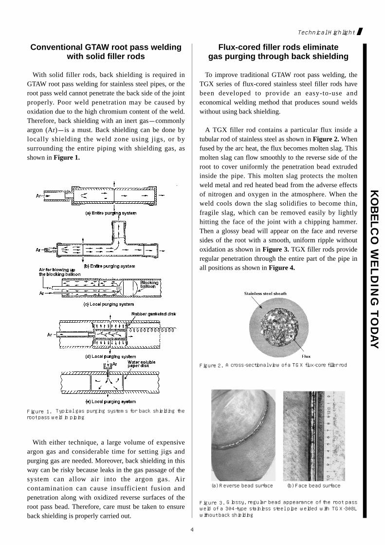
With solid filler rods, back shielding is required inGTAW root pass welding for stainless steel pipes, or theroot pass weld cannot penetrate the back side of the jointproperly. Poor weld penetration may be caused byoxidation due to the high chromium content of the weld.Therefore, back shielding with an inert gas-commonlyargon (Ar)-is a must. Back shielding can be done bylocally shielding the weld zone using jigs, or bysurrounding the entire piping with shielding gas, asshown in Figure 1.
Flux-cored filler rods eliminategas purging through back shielding
To improve traditional GTAW root pass welding, theTGX series of flux-cored stainless steel filler rods havebeen developed to provide an easy-to-use andeconomical welding method that produces sound weldswithout using back shielding.
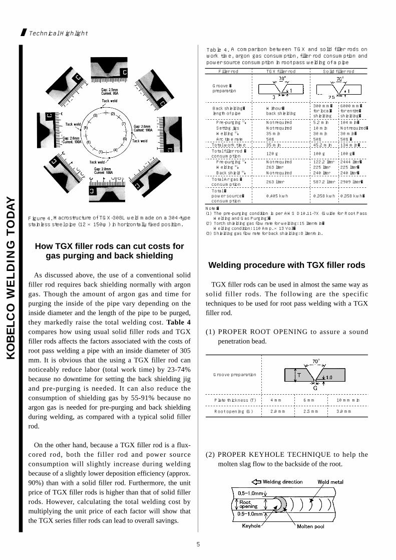
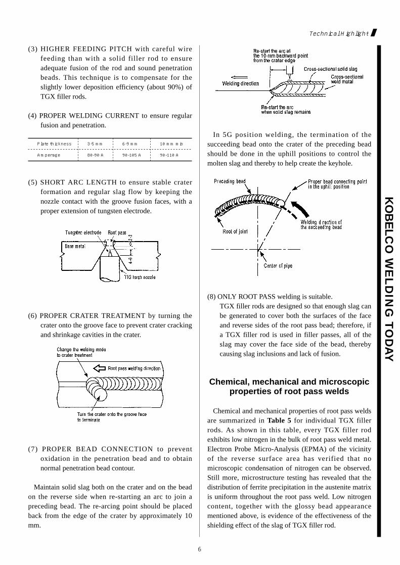
A TGX filler rod contains a particular flux inside atubular rod of stainless steel as shown in Figure 2. Whenfused by the arc heat, the flux becomes molten slag. Thismolten slag can flow smoothly to the reverse side of theroot to cover uniformly the penetration bead extrudedinside the pipe. This molten slag protects the moltenweld metal and red heated bead from the adverse effectsof nitrogen and oxygen in the atmosphere. When theweld cools down the slag solidifies to become thin,fragile slag, which can be removed easily by lightlyhitting the face of the joint with a chipping hammer.Then a glossy bead will appear on the face and reversesides of the root with a smooth, uniform ripple withoutoxidation as shown in Figure 3. TGX filler rods provideregular penetration through the entire part of the pipe inall positions as shown in Figure 4.
With either technique, a large volume of expensiveargon gas and considerable time for setting jigs andpurging gas are needed. Moreover, back shielding in thisway can be risky because leaks in the gas passage of thesystem can allow air into the argon gas. Aircontamination can cause insufficient fusion andpenetration along with oxidized reverse surfaces of theroot pass bead. Therefore, care must be taken to ensureback shielding is properly carried out.
Figure 1. Typical gas purging systems for back shielding theroot pass weld in piping
Figure 2. A cross-sectional view of a TGX flux-core filler rod
Figure 3. Glossy, regular bead appearance of the root passweld of a 304-type stainless steel pipe welded with TGX-308Lwithout back shielding
(a) Reverse bead surface (b) Face bead surface
5
KO
BELC
O W
EL
DIN
G T
OD
AY
Technical Highlight
How TGX filler rods can cut costs forgas purging and back shielding
As discussed above, the use of a conventional solidfiller rod requires back shielding normally with argongas. Though the amount of argon gas and time forpurging the inside of the pipe vary depending on theinside diameter and the length of the pipe to be purged,they markedly raise the total welding cost. Table 4compares how using usual solid filler rods and TGXfiller rods affects the factors associated with the costs ofroot pass welding a pipe with an inside diameter of 305mm. It is obvious that the using a TGX filler rod cannoticeably reduce labor (total work time) by 23-74%because no downtime for setting the back shielding jigand pre-purging is needed. It can also reduce theconsumption of shielding gas by 55-91% because noargon gas is needed for pre-purging and back shieldingduring welding, as compared with a typical solid fillerrod.
On the other hand, because a TGX filler rod is a flux-cored rod, both the filler rod and power sourceconsumption will slightly increase during weldingbecause of a slightly lower deposition efficiency (approx.90%) than with a solid filler rod. Furthermore, the unitprice of TGX filler rods is higher than that of solid fillerrods. However, calculating the total welding cost bymultiplying the unit price of each factor will show thatthe TGX series filler rods can lead to overall savings.
Welding procedure with TGX filler rods
TGX filler rods can be used in almost the same way assolid filler rods. The following are the specifictechniques to be used for root pass welding with a TGXfiller rod.
(1) PROPER ROOT OPENING to assure a soundpenetration bead.
(2) PROPER KEYHOLE TECHNIQUE to help themolten slag flow to the backside of the root.
Figure 4. Macrostructure of TGX-308L weld made on a 304-typestainless steel pipe (12 ×150φ) in horizontally fixed position.
Filler rod
Groove �preparation
Back shielding�length of pipe
Pre-purging (1)�
Pre-purging (1)� Not required 122.2 liter 2444 liter�Welding (2)� 263 liter 225 liter 225 liter�Back shield (3)� Not required 240 liter 240 liter�
Total work timeTotal filler rod �consumption
Total Ar gas �consumption
120 g 100 g 100 g�
35 min
263 liter 587.2 liter 2909 liter�
Total �power source�consumption
0.405 kwh 0.358 kwh 0.358 kwh�
45.2 min 134 min�
Not required 5.2 min 104 min�Setting jigs Not required 10 min Not required�Welding (2)� 35 min 30 min 30 min�Arc time rate 50% 50% 50%�
Without�back shielding
300 mm�for local�shielding
6000 mm�for entire�shielding�
TGX filler rod Solid filler rod
Note:�(1) The pre-purging condition is per AWS D10.11-7X (Guide for Root Pass Welding and Gas Purging)�
(2) Torch shielding gas flow rate for welding: 15 liter/min�Welding condition: 110 Amp. ×13 Volt�
(3) Shielding gas flow rate for back shielding: 8 liter/min.
Table 4. A comparison between TGX and solid filler rods onwork time, argon gas consumption, filler rod consumption andpower source consumption in root pass welding of a pipe
Groove preparation
Plate thickness (T)
Root opening (G)
4 mm 6 mm 10 mm min
2.0 mm 2.5 mm 3.0 mm
KO
BELC
O W
EL
DIN
G T
OD
AY
6
Technical Highlight
(3) HIGHER FEEDING PITCH with careful wirefeeding than with a solid filler rod to ensureadequate fusion of the rod and sound penetrationbeads. This technique is to compensate for theslightly lower deposition efficiency (about 90%) ofTGX filler rods.
(4) PROPER WELDING CURRENT to ensure regularfusion and penetration.
In 5G position welding, the termination of thesucceeding bead onto the crater of the preceding beadshould be done in the uphill positions to control themolten slag and thereby to help create the keyhole.
(8) ONLY ROOT PASS welding is suitable. TGX filler rods are designed so that enough slag canbe generated to cover both the surfaces of the faceand reverse sides of the root pass bead; therefore, ifa TGX filler rod is used in filler passes, all of theslag may cover the face side of the bead, therebycausing slag inclusions and lack of fusion.
Chemical, mechanical and microscopicproperties of root pass welds
Chemical and mechanical properties of root pass weldsare summarized in Table 5 for individual TGX fillerrods. As shown in this table, every TGX filler rodexhibits low nitrogen in the bulk of root pass weld metal.Electron Probe Micro-Analysis (EPMA) of the vicinityof the reverse surface area has verified that nomicroscopic condensation of nitrogen can be observed.Still more, microstructure testing has revealed that thedistribution of ferrite precipitation in the austenite matrixis uniform throughout the root pass weld. Low nitrogencontent, together with the glossy bead appearancementioned above, is evidence of the effectiveness of theshielding effect of the slag of TGX filler rod.
(5) SHORT ARC LENGTH to ensure stable craterformation and regular slag flow by keeping thenozzle contact with the groove fusion faces, with aproper extension of tungsten electrode.
(6) PROPER CRATER TREATMENT by turning thecrater onto the groove face to prevent crater crackingand shrinkage cavities in the crater.
(7) PROPER BEAD CONNECTION to preventoxidation in the penetration bead and to obtainnormal penetration bead contour.
Maintain solid slag both on the crater and on the beadon the reverse side when re-starting an arc to join apreceding bead. The re-arcing point should be placedback from the edge of the crater by approximately 10mm.
Plate thickness
Amperage 80-90 A 90-105 A 90-110 A
3-5 mm 6-9 mm 10 mm min
7
KO
BELC
O W
EL
DIN
G T
OD
AY
Technical Highlight
Filler rod for�root pass (1)�Filler rod and wire for�filler pass (2)�Type of base metal�(Thickness, mm)Welding positionWelding current�(DCEN for GTAW,�DCEP for GMAW)
Chemical composition and �
ferrite content of �
root pass weld metal (%) (3)�
Root pass:�105A�
Filler pass:�150-180A
Root pass:�105A�
Filler pass:�150-180A
Root pass:�105A�
Filler pass:�180A
Root pass:�105A�
Filler pass:�180A
Flat
C 0.040 0.018 0.047 0.028SiMnNiCrMoNbTiN
FS, FNSD, F%DD, FN
X-ray test per JIS 1st grade593�N/mm2�(Base�metal)
Joint tension test�(Fracture position)
2T-radius side and�root bend test No defect No defect No defect No defect
551 �N/mm2�(Base�metal)
634 �N/mm2��(Weld�metal)
-�
1st grade 1st grade 1st grade5.5 8 8 57 7.5 7 6
4.6-5.7 7.1-7.6 6.9-8.5 4.4-6.20.044 0.041 0.038 0.044-� -� -� 0.07-� -� -� 0.44-� 2.17 0.35 -�18.89 18.93 19.47 18.679.72 12.34 9.99 10.351.11 1.48 1.36 1.780.55 0.64 0.56 0.65
Flat Flat Flat
304�(9)
316L�(9)
Mild steel /�316 (19)
321�(20)
TGS-308�(2.4φ)
TGS-316L�(2.4φ)
DW-309L�(1.2φ)
DW-347�(1.2φ)
TGX-308L�(2.2φ)
TGX-316L�(2.2φ)
TGX-309L�(2.2φ)
TGX-347�(2.2φ)
Note:�(1) Torch shielding gas: Ar (without back shielding)�(2) Torch shielding gas: Ar for GTAW; CO2 for GMAW�(3) FS: Ferrite scope; SD: Schaeffler diagram;�DD: Delong diagram
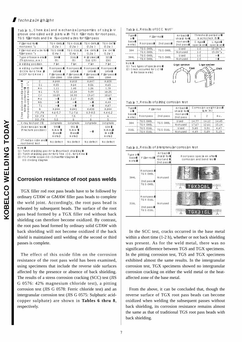
Table 5. Chemical and mechanical properties of single-Vgroove one-sided weld joints with TGX filler rods for root pass,TGS filler rods and DW flux-cored wires for filler pass
Type�of�base�metal Root pass�
304
304L TGS-308LTGX-308L Not used 1-2 -�
Used 1-2 -�TGS-308L
TGS-308LTGX-308L Not used 1-2 15-20 (2)�
Used 1-2 15-20 (2)�TGS-308L
2nd pass� C-type�specimen�
L-type�specimen�
Filler rod� Ar back�shield for�root and�2nd pass�
Threshold period of�macrocrack (h)�
Note:�(1) Two types of specimens:�(2) Crack occurred for 1-2 h�in the base metal
Table 6. Results of SCC test (1)
Type�of�base�metal Root pass 2nd pass 1 2 Av.
Filler rod Ar back�shield for�root and�2nd pass
Corrosion weight loss�(g/m2/h)
304
316L
TGS-308LTGX-308LTGS-316LTGX-316L Not used 4.49 5.89 5.19
Used 5.03 3.91 4.47TGS-316L
Not used 17.67 12.61 15.14Used 14.77 14.12 14.45TGS-308L
Table 7. Results of pitting corrosion test
Type of�base�metal�
Filler rod�
Ar back�shield for�root and �2nd pass�
Root pass specimen after�corrosion and bend test�
304L
316L Not used
Root pass:�TGX-316L
2nd pass:�TGS-316L
Not used
Root pass:�TGX-308L
2nd pass:�TGS-308L
Table 8. Results of intergranular corrosion test
Corrosion resistance of root pass welds
TGX filler rod root pass beads have to be followed byordinary GTAW or GMAW filler pass beads to completethe weld joint. Accordingly, the root pass bead isreheated by subsequent beads. The surface of the rootpass bead formed by a TGX filler rod without backshielding can therefore become oxidized. By contrast,the root pass bead formed by ordinary solid GTAW withback shielding will not become oxidized if the backshield is maintained until welding of the second or thirdpasses is complete.
The effect of this oxide film on the corrosionresistance of the root pass weld has been examined,using specimens that include the reverse side surfacesaffected by the presence or absence of back shielding.The results of a stress corrosion cracking (SCC) test (JISG 0576: 42% magnesium chloride test), a pittingcorrosion test (JIS G 0578: Ferric chloride test) and anintergranular corrosion test (JIS G 0575: Sulphuric acid-copper sulphate) are shown in Tables 6 thru 8,respectively.
In the SCC test, cracks occurred in the base metalwithin a short time (1-2 h), whether or not back shieldingwas present. As for the weld metal, there was nosignificant difference between TGS and TGX specimens.In the pitting corrosion test, TGS and TGX specimensexhibited almost the same results. In the intergranularcorrosion test, TGX specimens showed no intergranularcorrosion cracking on either the weld metal or the heat-affected zone of the base metal.
From the above, it can be concluded that, though thereverse surface of TGX root pass beads can becomeoxidized when welding the subsequent passes withoutback shielding, its corrosion resistance remains almostthe same as that of traditional TGS root pass beads withback shielding.
8
KO
BELC
O W
EL
DIN
G T
OD
AY
Technical Terms Explanation
Welded constructions can rapidly fracture in anunstable manner due to welding defects and fatiguecracks occurring in the stress-concentrated areas of aweldment under lower stresses than expected. Unstablefractures or brittle fractures can occur in unexpectedlyshort periods of time before the end of the designedservice life of the structure. This kind of fracturetherefore can cause serious damage of a weldedconstruction.
To prevent unstable fractures, the field of fracturemechanics has been established. Investigations intofracture parameters allow a construction’s fracturetoughness to be estimated in a systematic manner.
The fracture parameters include stress intensity factor(K), J-integral and Crack Tip Opening Displacement(CTOD). Today, CTOD is most widely employed instructural and component design and in assessment ofthe acceptability of crack extension and allowableapplied loads. CTOD testing has been used mainly forcarbon-manganese and low alloy steel in theductile/brittle transition temperature range, and hasfound much use in weld procedure tests for work onNorth Sea offshore structures.
CTOD testing has been specified by British Standard(BS 7448-91), Japan Welding Engineering Standard(WES 1108-95) and American ASTM standard (ASTME1290-93).
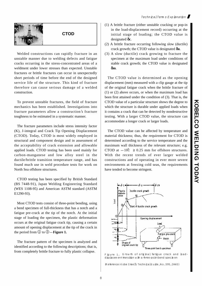
Most CTOD tests consist of three-point bending, usinga bend specimen of full-thickness that has a notch and afatigue pre-crack at the tip of the notch. At the initialstage of loading the specimen, the plastic deformationoccurs at the original fatigue crack tip, causing a certainamount of opening displacement at the tip of the crack inthe period from ① to ③-Figure 1.
The fracture pattern of the specimen is analyzed andidentified according to the following descriptions; that is,from completely brittle fracture to fully plastic collapse.
(1) A brittle fracture (either unstable cracking or pop-inin the load-displacement record) occurring at theinitial stage of loading; the CTOD value isdesignated δδc.
(2) A brittle fracture occurring following slow (ductile)crack growth; the CTOD value is designated δδu.
(3) A slow (ductile) crack growing to fracture thespecimen at the maximum load under conditions ofstable crack growth; the CTOD value is designatedδδm.
The CTOD value is determined as the openingdisplacement (mm) measured with a clip gauge at the tipof the original fatigue crack when the brittle fracture of(1) or (2) above occurs, or when the maximum load hasbeen first attained under the condition of (3). That is, theCTOD value of a particular structure shows the degree towhich the structure is durable under applied loads whenit contains a crack that can be detected by nondestructivetesting. With a larger CTOD value, the structure canaccommodate a longer crack or larger loads.
The CTOD value can be affected by temperature andmaterial thickness; thus, the requirement for CTOD isdetermined according to the service temperature and themaximum wall thickness of the relevant structure; e.g.CTOD at -10℃ ≥ 0.25 mm for offshore structures.With the recent trends of ever larger weldedconstructions and of operating in ever more severeenvironments at freezing cold seas, the requirementshave tended to become stringent.
Figure 1. Growth of original fatigue crack and load-displacement transition with a three-point bend specimen
(Reference: Kobe Steel’s Technical Guide, No. 395, 2003)
CTOD
KO
BELC
O W
EL
DIN
G T
OD
AY
9
Bulletin
Fighting against extreme climate
A happy new year to dear readers of Kobelco WeldingToday! I am greeting you from China. Tangshan City,Hebei Province, where I am working, is situated in aposition to form a triangle with the two nearby cities ofBeijing and Tienchin.
Here in Tangshan winter comes immediately aftersummer, and while the highest temperature in summerreaches 40℃, the winter lows sink to -20℃! With suchan extreme temperature difference, maintaining goodhealth is very difficult and you can never avoid catchinga cold at least once.
Yet, we, the members of the Sales Department, arebriskly developing our activities, supported by ourcustomers, and crisscrossing this vast land of China in allweather, fair or foul, windy or calm, or scorching orfreezing. For, we are a quite young company thatreached its first anniversary only last November, and thatis full of the most youthful energy among othercompanies in the Kobelco Group.
We are determined to continue our strenuous efforts,planning to run north to instruct on how to adjustwelding conditions, south to speak for high efficiencyachieved by our products, east to hold a training courseon welding skill and west to observe actual productionwelding by DREAM-KOBELCO, our sales car shown inthe photo.
Last but not least, may the year 2005 be a splendidyear for you all and for us!
Greetings from KWAI
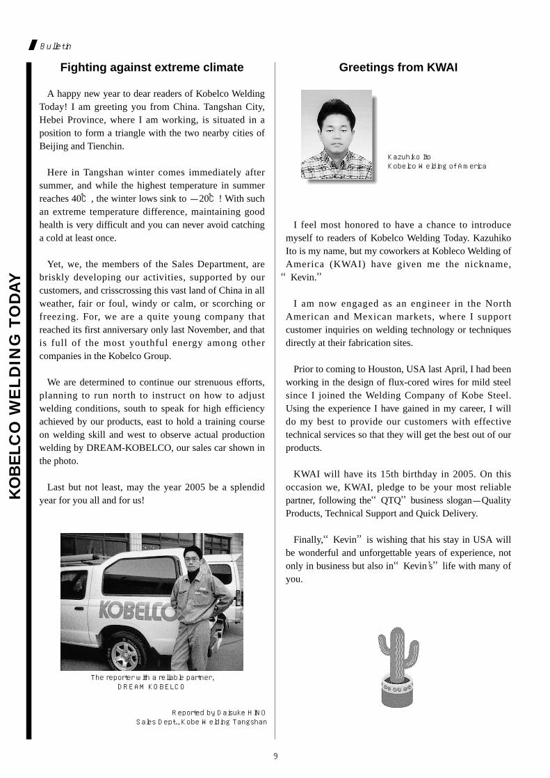
I feel most honored to have a chance to introducemyself to readers of Kobelco Welding Today. KazuhikoIto is my name, but my coworkers at Kobleco Welding ofAmerica (KWAI) have given me the nickname,“Kevin.”
I am now engaged as an engineer in the NorthAmerican and Mexican markets, where I supportcustomer inquiries on welding technology or techniquesdirectly at their fabrication sites.
Prior to coming to Houston, USA last April, I had beenworking in the design of flux-cored wires for mild steelsince I joined the Welding Company of Kobe Steel.Using the experience I have gained in my career, I willdo my best to provide our customers with effectivetechnical services so that they will get the best out of ourproducts.
KWAI will have its 15th birthday in 2005. On thisoccasion we, KWAI, pledge to be your most reliablepartner, following the“QTQ”business slogan-QualityProducts, Technical Support and Quick Delivery.
Finally,“Kevin”is wishing that his stay in USA willbe wonderful and unforgettable years of experience, notonly in business but also in“Kevin’s”life with many ofyou.
The reporter with a reliable partner, DREAM KOBELCO
Kazuhiko ItoKobelco Welding of America
Reported by Daisuke HINOSales Dept., Kobe Welding Tangshan
10
KO
BELC
O W
EL
DIN
G T
OD
AY
Bulletin
BEIJING ESSEN WELDING
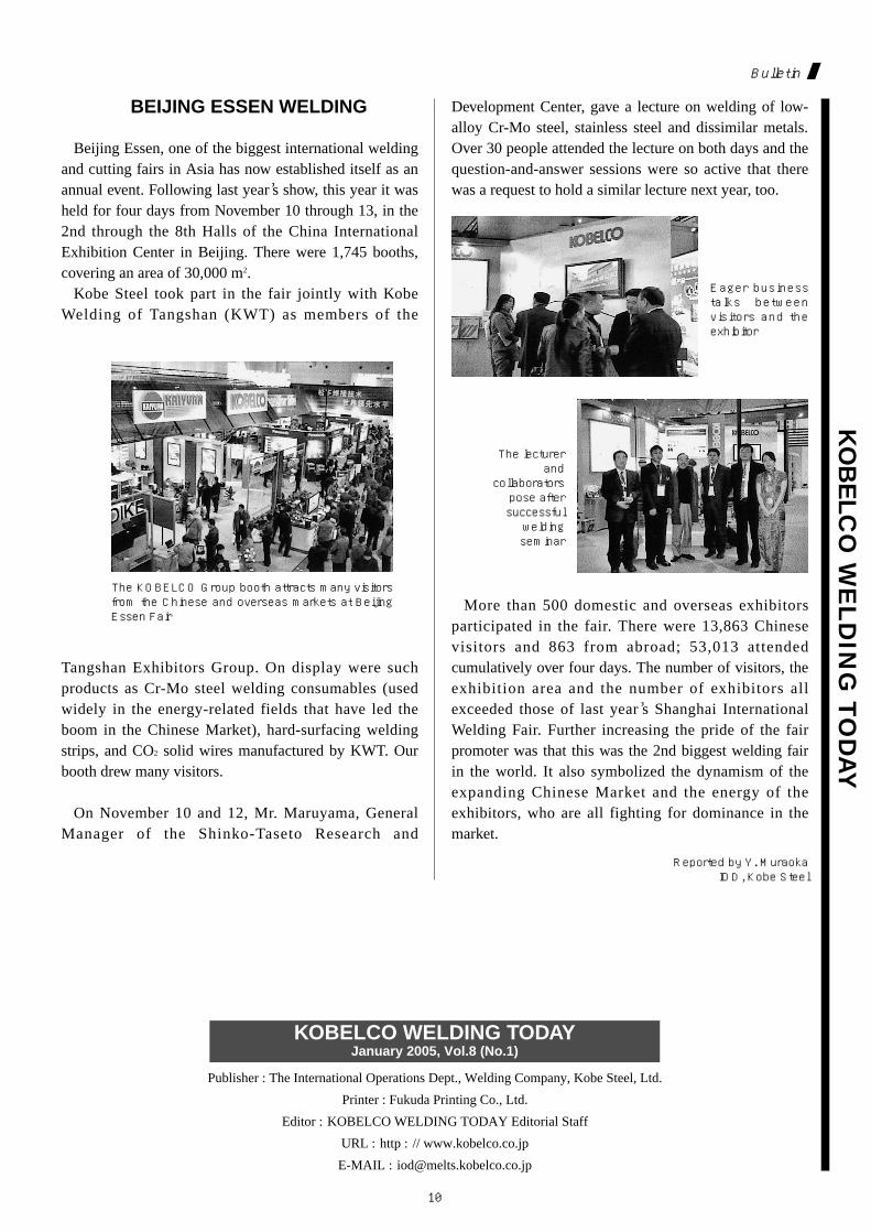
Beijing Essen, one of the biggest international weldingand cutting fairs in Asia has now established itself as anannual event. Following last year’s show, this year it washeld for four days from November 10 through 13, in the2nd through the 8th Halls of the China InternationalExhibition Center in Beijing. There were 1,745 booths,covering an area of 30,000 m2.
Kobe Steel took part in the fair jointly with KobeWelding of Tangshan (KWT) as members of the
Tangshan Exhibitors Group. On display were suchproducts as Cr-Mo steel welding consumables (usedwidely in the energy-related fields that have led theboom in the Chinese Market), hard-surfacing weldingstrips, and CO2 solid wires manufactured by KWT. Ourbooth drew many visitors.
On November 10 and 12, Mr. Maruyama, GeneralManager of the Shinko-Taseto Research and
Development Center, gave a lecture on welding of low-alloy Cr-Mo steel, stainless steel and dissimilar metals.Over 30 people attended the lecture on both days and thequestion-and-answer sessions were so active that therewas a request to hold a similar lecture next year, too.
More than 500 domestic and overseas exhibitorsparticipated in the fair. There were 13,863 Chinesevisitors and 863 from abroad; 53,013 attendedcumulatively over four days. The number of visitors, theexhibition area and the number of exhibitors allexceeded those of last year’s Shanghai InternationalWelding Fair. Further increasing the pride of the fairpromoter was that this was the 2nd biggest welding fairin the world. It also symbolized the dynamism of theexpanding Chinese Market and the energy of theexhibitors, who are all fighting for dominance in themarket.
The KOBELCO Group booth attracts many visitorsfrom the Chinese and overseas markets at BeijingEssen Fair
Eager businesstalks betweenvisitors and theexhibitor
The lecturerand
collaboratorspose aftersuccessfulweldingseminar
Reported by Y. Muraoka IOD, Kobe Steel
Publisher : The International Operations Dept., Welding Company, Kobe Steel, Ltd.
Printer : Fukuda Printing Co., Ltd.
Editor : KOBELCO WELDING TODAY Editorial Staff
URL : http : // www.kobelco.co.jp
E-MAIL : [email protected]
KOBELCO WELDING TODAYJanuary 2005, Vol.8 (No.1)