KMA36 Contactless Rotational and Linear Encoder · KMA36 Contactless Rotational and Linear Encoder...
15
KMA36 Contactless Rotational and Linear Encoder KMA36 Rev 7 www.meas-spec.com 2014-April 1/15 • Contactless Absolute 360° (180°) angle measurement • Incremental mode • Linear mode • Standard I2C Interface (100 kHz) • Programmable resolution up to 13 bit (0.04 degree) • Very low hysteresis • High accuracy mode • User programmable parameters • Low power mode • Sleep and automatic wake-up over I2C • Programmable zero position • Device address hardware configurable • Small Pb-Free package (TSSOP20) • RoHS compliant DESCRIPTION The KMA36 is a highly reliable universal magnetic position sensor for precise rotational or linear measurement with a resolution up to 0.04 degree. These digital position sensors feature a system-on-chip technology that combines a magnetoresistive element along with analog to digital converter and signal processing in a standard small package. By using Anisotropic Magneto Resistive (AMR) technology, the KMA36 is able to determine accuractly and non-contacting the magnetic angle of an external magnet over 360°, as well as the incremental position on a magnetic pole strip with 5 mm pole length. Its sleep and low power mode as well as automatic wake-up over I2C – make the KMA36 ideal for many battery applications. Position data can be transmitted using a PWM or digital two-wire (SDA, SCL) communication bus. Using the programmable parameters of this digital position sensor, the user can have access to a wide range of configuration to ensure the maximum of freedom and functionalities. Used as both a linear position sensor or a rotary position sensor, these KMA36 magnetoresistive sensors designed by MEAS (Measurement Specialties) are insensitive to magnetic drift due to mechanical tolerances, changes in temperature or thermal stress. The maintenance-free operation and high bandwidth of this universal magnetic encoder makes it a good choice for dynamic applications in harsh environments. KEY-FEATURES Resolution 13 Bit / 0.04 degree Operating power supply range of 3V to 5.5V 3.0 – 5.5V Operating temperature - 25 - +85 °C Average current 10 – 30 mA Sleep current 1.2 mA Data Update rate 24 – 720 Hz I 2 C Clockrate Up to 100 kBit/s APPLICATIONS Industrial environment Robotics Harsh environment Potentiometer Handling machine Motor motion control Machine tools
Transcript of KMA36 Contactless Rotational and Linear Encoder · KMA36 Contactless Rotational and Linear Encoder...

KMA36 Contactless Rotational and Linear Encoder
KMA36 Rev 7 www.meas-spec.com 2014-April
1/15
• Contactless Absolute 360° (180°) angle measurement • Incremental mode • Linear mode • Standard I2C Interface (100 kHz) • Programmable resolution up to 13 bit (0.04 degree) • Very low hysteresis • High accuracy mode • User programmable parameters • Low power mode • Sleep and automatic wake-up over I2C • Programmable zero position • Device address hardware configurable • Small Pb-Free package (TSSOP20) • RoHS compliant
DESCRIPTION
The KMA36 is a highly reliable universal magnetic position sensor for precise rotational or linear measurement with a resolution up to 0.04 degree. These digital position sensors feature a system-on-chip technology that combines a magnetoresistive element along with analog to digital converter and signal processing in a standard small package. By using Anisotropic Magneto Resistive (AMR) technology, the KMA36 is able to determine accuractly and non-contacting the magnetic angle of an external magnet over 360°, as well as the incremental position on a magnetic pole strip with 5 mm pole length. Its sleep and low power mode as well as automatic wake-up over I2C – make the KMA36 ideal for many battery applications. Position data can be transmitted using a PWM or digital two-wire (SDA, SCL) communication bus. Using the programmable parameters of this digital position sensor, the user can have access to a wide range of configuration to ensure the maximum of freedom and functionalities. Used as both a linear position sensor or a rotary position sensor, these KMA36 magnetoresistive sensors designed by MEAS (Measurement Specialties) are insensitive to magnetic drift due to mechanical tolerances, changes in temperature or thermal stress. The maintenance-free operation and high bandwidth of this universal magnetic encoder makes it a good choice for dynamic applications in harsh environments. KEY-FEATURES
Resolution 13 Bit / 0.04 degree Operating power supply range of 3V to 5.5V 3.0 – 5.5V Operating temperature - 25 - +85 °C Average current 10 – 30 mA Sleep current 1.2 mA Data Update rate 24 – 720 Hz I2C Clockrate Up to 100 kBit/s
APPLICATIONS
Industrial environment Robotics Harsh environment Potentiometer Handling machine Motor motion control Machine tools
KMA36 Contactless Rotational and Linear Encoder
KMT36 Rev 7 www.meas-spec.com 2014-April
2/15
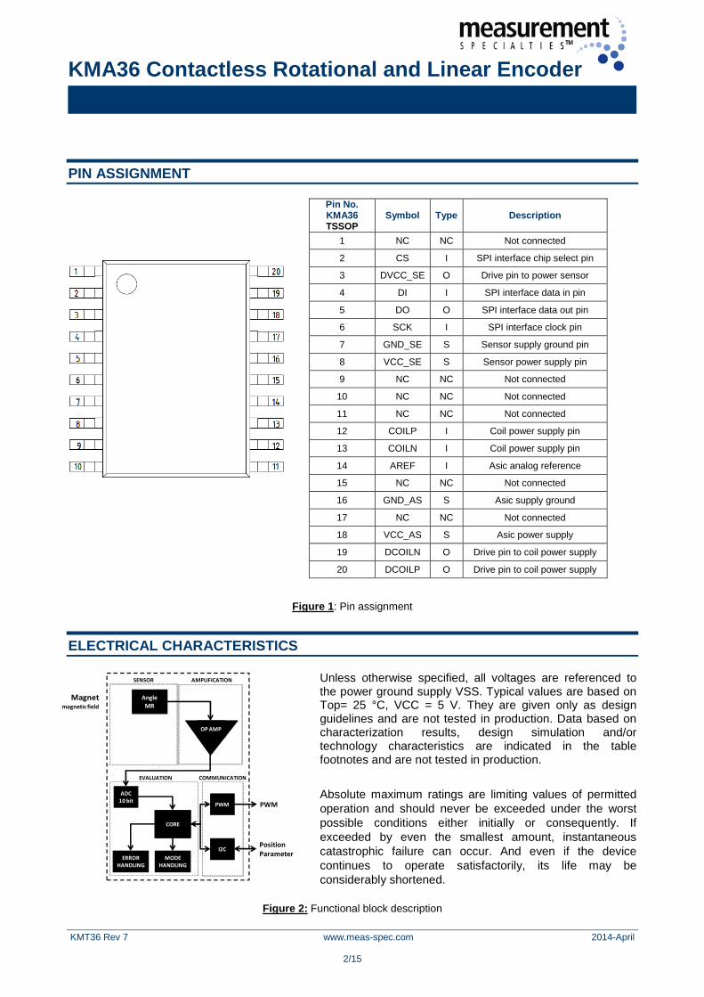
PIN ASSIGNMENT
Pin No. KMA36 TSSOP
Symbol Type Description
1 NC NC Not connected
2 CS I SPI interface chip select pin
3 DVCC_SE O Drive pin to power sensor
4 DI I SPI interface data in pin
5 DO O SPI interface data out pin
6 SCK I SPI interface clock pin
7 GND_SE S Sensor supply ground pin
8 VCC_SE S Sensor power supply pin
9 NC NC Not connected
10 NC NC Not connected
11 NC NC Not connected
12 COILP I Coil power supply pin
13 COILN I Coil power supply pin
14 AREF I Asic analog reference
15 NC NC Not connected
16 GND_AS S Asic supply ground
17 NC NC Not connected
18 VCC_AS S Asic power supply
19 DCOILN O Drive pin to coil power supply
20 DCOILP O Drive pin to coil power supply
Figure 1: Pin assignment ELECTRICAL CHARACTERISTICS
Unless otherwise specified, all voltages are referenced to the power ground supply VSS. Typical values are based on Top= 25 °C, VCC = 5 V. They are given only as design guidelines and are not tested in production. Data based on characterization results, design simulation and/or technology characteristics are indicated in the table footnotes and are not tested in production. Absolute maximum ratings are limiting values of permitted operation and should never be exceeded under the worst possible conditions either initially or consequently. If exceeded by even the smallest amount, instantaneous catastrophic failure can occur. And even if the device continues to operate satisfactorily, its life may be considerably shortened.
Figure 2: Functional block description
Angle MR
Magnet magnetic field
AMPLIFICATION
ADC10 bit
CORE
ERRORHANDLING
I2C
SENSOR
EVALUATION COMMUNICATION
OP AMP
PWM
MODEHANDLING
PositionParameter
PWM
KMA36 Contactless Rotational and Linear Encoder
KMT36 Rev 7 www.meas-spec.com 2014-April
3/15
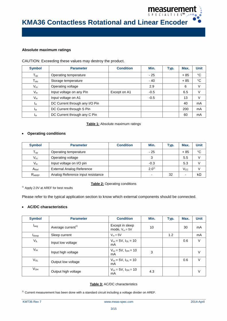
Absolute maximum ratings CAUTION: Exceeding these values may destroy the product.
Symbol Parameter Condition Min. Typ. Max. Unit
Top Operating temperature - 25 + 85 °C Tsto Storage temperature - 40 + 85 °C Vcc Operating voltage 2.9 6 V Vin Input voltage on any Pin Except on A1 -0.5 6.5 V Vin Input voltage on A1 -0.5 13 V Iin DC Current through any I/O Pin 40 mA Iin DC Current through S Pin 200 mA Iin DC Current through any C Pin 60 mA
Table 1: Absolute maximum ratings
• Operating conditions
Symbol Parameter Condition Min. Typ. Max. Unit
Top Operating temperature - 25 + 85 °C Vcc Operating voltage 3 5.5 V Vin Input voltage on I/O pin -0.3 5.3 V ARef External Analog Reference 2.01) VCC V
RAREF Analog Reference input resistance - 32 - kΩ
Table 2: Operating conditions 1) Apply 2.0V at AREF for best results Please refer to the typical application section to know which external components should be connected. • AC/DC characteristics
Symbol Parameter Condition Min. Typ. Max. Unit
Iavg Average current1) Except in sleep mode, Vcc = 5V 10 30 mA
Isleep Sleep current Vcc = 5V 1.2 mA VIL Input low voltage Vcc = 5V, IOL = 10
mA 0.6 V
VIH Input high voltage Vcc = 5V, IOH = 10
mA 3
V
VOL Output low voltage Vcc = 5V, IOL = 10 mA
0.6 V
VOH Output high voltage Vcc = 5V, IOH = 10
mA 4.3
V
Table 3: AC/DC characteristics
1) Current measurement has been done with a standard circuit including a voltage divider on AREF.

KMA36 Contactless Rotational and Linear Encoder
KMT36 Rev 7 www.meas-spec.com 2014-April
4/15
• System parameters
Symbol Parameter Condition Min. Typ. Max. Unit
fdata Update rate1) 2) 24 720 Hz tstart Starting time 5 ms αr Resolution H0=25 kA/m 3) 13 Bit ΔαL Linearity error H0=25 kA/m 3)
Top=25°C ±0.3 ±1 °
ΔαH Hysteresis error H0=25 kA/m 3)
Top=25°C ±0.1 ±0.25 °
Vbwn Brown-out reset voltage 2.7 V tbwn Brown-out reset pulse width 2 µs Hy Applied magnetic field 15 25 60 kA/m
RCOIL Internal coil resistance 75 100 150 Ω ΔPWM PWM output resolution 10 bit fPWM PWM frequency 7.8 kHz
Table 4: System parameters
1) Maximum is measured in speed mode with minimum oversampling. Minimum is measured with maximum oversampling. 2) When using the analog-output configuration then update rate is fixed at 88Hz 3) System parameters apply only for recommended measurement setup (please refer to the arrangement section)
SYSTEM OUTPUT
The system has two possible hardware output configurations: two-wire interface or analog output. • Analog Output The system has a Pulse Width Modulation unit with 10 bit resolution which can be easily coupled with a first order low-pass filter1) to generate an analog output between Vss and Vcc corresponding to 0° and 360°. In this hardware configuration, all internal registers are loaded with initial values. No digital configuration is necessary, all available configurations can be set by changing the hardware setup2) of the KMA36. 1) Please refer to the typical application section for further information. 2) Please refer to the hardware configuration section for further information. • I2C (Digital Output) The KMA36 has an I2C Interface unit (two-wire interface, standard I²C-bus specification defined by Philips Semiconductors) with an 8-bit data bus which can be easily used to retrieve measurement and configuration information. (Please refer to the two-wire interface section for details)
Update rate fdata = 1 / (1.4 msec x oversampling / const)
SPD Bit const
0 1 1 2
KMA36 Contactless Rotational and Linear Encoder
KMT36 Rev 7 www.meas-spec.com 2014-April
5/15
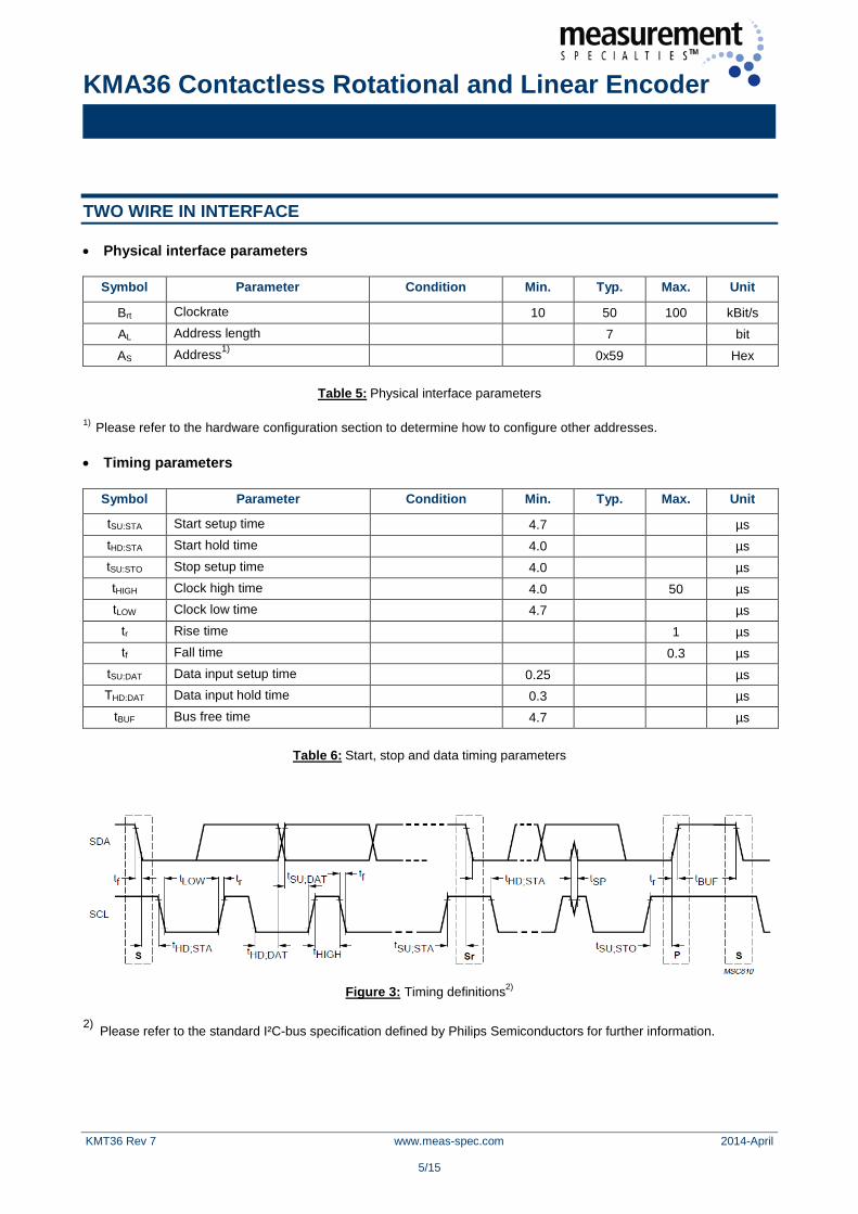
TWO WIRE IN INTERFACE
• Physical interface parameters
Symbol Parameter Condition Min. Typ. Max. Unit
Brt Clockrate 10 50 100 kBit/s AL Address length 7 bit AS Address1) 0x59 Hex
Table 5: Physical interface parameters
1) Please refer to the hardware configuration section to determine how to configure other addresses. • Timing parameters
Symbol Parameter Condition Min. Typ. Max. Unit
tSU:STA Start setup time 4.7 µs tHD:STA Start hold time 4.0 µs tSU:STO Stop setup time 4.0 µs tHIGH Clock high time 4.0 50 µs tLOW Clock low time 4.7 µs
tr Rise time 1 µs tf Fall time 0.3 µs
tSU:DAT Data input setup time 0.25 µs THD:DAT Data input hold time 0.3 µs
tBUF Bus free time 4.7 µs
Table 6: Start, stop and data timing parameters
Figure 3: Timing definitions2)
2) Please refer to the standard I²C-bus specification defined by Philips Semiconductors for further information.

KMA36 Contactless Rotational and Linear Encoder
KMT36 Rev 7 www.meas-spec.com 2014-April
6/15
• Registers (Overview) The KMA36 contains the following I/O registers:
Registers of the KMA36-SPI Register Size Read/Write Function
CONF 8 bit R/W Configuration bits RES 16 bit R/W Resolution MA 16 bit R Magnetic angle MIA 32 bit R Magnetic incremental angle
Table 7: Registers of the KMA36 • I2C Bus The KMA36 is always operating as a pure slave. • I2C Reading data It is possible to read up to seven bytes as described in the following figure. No special protocol is used by the reading-data process.
TWI - Read data
Byte 0 1 2 3 4 5 6 MA0 MA1 ILC0 ILC1 ILC2 ILC3 KCONF
Read/Write R R R R R R R Initial value 0x00 0x00 0x00 0x00 0x00 0x00 0x03
Byte 0:1 - MA1:0: Magnetic angle Unsigned integer giving the magnetic angle in degree with the configured resolution
Byte 2:5 - ILC3:0: Incremental linear counter
Signed long giving the incremental linear counter in degree with the configured resolution.
Byte 6 - KCONF: Configuration register Unsigned char giving the configuration register value.
Table 8: Read data • I2C Writing data (general) The KMA36 can be controlled using two internal registers. The configuration (KCONF) is an 8-bit register and the resolution (KRES) is a 16-bit register. To write the 16-bit register (KRES) through the two-wire interface with an 8-bit data bus, it is necessary to send the high byte first and then the low byte. In order to change the KMA configuration, four bytes should be sent through the two-wire 8-bit data bus. The first three bytes correspond to the configuration and resolution registers. The last byte contains a 8-Bit Cyclic Redundancy Check (CRC) value which can be calculated as described in the example.
KMA36 Contactless Rotational and Linear Encoder
KMT36 Rev 7 www.meas-spec.com 2014-April
7/15
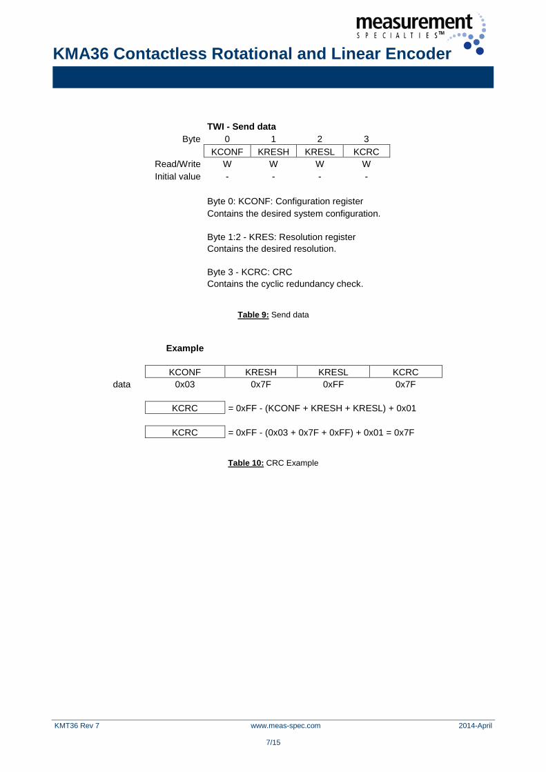
TWI - Send data Byte 0 1 2 3
KCONF KRESH KRESL KCRC Read/Write W W W W Initial value - - - -
Byte 0: KCONF: Configuration register Contains the desired system configuration. Byte 1:2 - KRES: Resolution register Contains the desired resolution. Byte 3 - KCRC: CRC Contains the cyclic redundancy check.
Table 9: Send data
Example KCONF KRESH KRESL KCRC
data 0x03 0x7F 0xFF 0x7F KCRC = 0xFF - (KCONF + KRESH + KRESL) + 0x01
KCRC = 0xFF - (0x03 + 0x7F + 0xFF) + 0x01 = 0x7F
Table 10: CRC Example

KMA36 Contactless Rotational and Linear Encoder
KMT36 Rev 7 www.meas-spec.com 2014-April
8/15
• KCONF (Configuration register) The configuration register is used to control and monitor the status and modes of the system:
KCONF - Configuration register
Bit 7 6 5 4 3 2 1 0 SLPE - LINE MIAE LPWRE SPDE OVS1 OVS0
Read/Write W R/W R/W R/W R/W R/W R/W R/W Initial value 0 0 0 0 0 0 1 0
Bit 7 - SLPE: Sleep mode enable Writing this bit to one enables the sleep mode. This bit will be always set to zero by hardware. Bit 5 - LINE: Linear mode enable Writing this bit to one disables the rotational mode and enables the linear mode.
Bit 4 - MIAE: Incremental mode enable
Writing this bit to one enables the incremental angle counter. By writing it to zero, the counter mode is turned off and the counter set to 0.
Bit 3 - LPWRE: Low power mode enable
Writing this bit to one enables the low power mode.
Bit 2 - SPDE: Speed mode enable
Writing this bit to one enables the fast speed mode. Bit 1:0 - OVS1:0: Oversampling These bits determines the accuracy of the angle evaluation.
Table 11: KCONF – Configuration Register
The system has three possible main configurations: • Rotational measurement used to measure the angle of a rotating magnet disc centered above the magnetic sensor center of the KMA36. 1) • Linear measurement used to measure the linear movement of the KMA36 along a magnetic pole strip with 5mm pole length. A lookup table is used for internal error correction 1) • Sleep mode used to power down the KMA36. Wake up is initiated by I2C communication 1) Please refer to the arrangement section. • CNT-Bit (KCONF register) In addition, there is an incremental counter implemented, which can be enabled by writing a one to the CNT-Bit in the KCONF register.
KMA36 Contactless Rotational and Linear Encoder
KMT36 Rev 7 www.meas-spec.com 2014-April
9/15
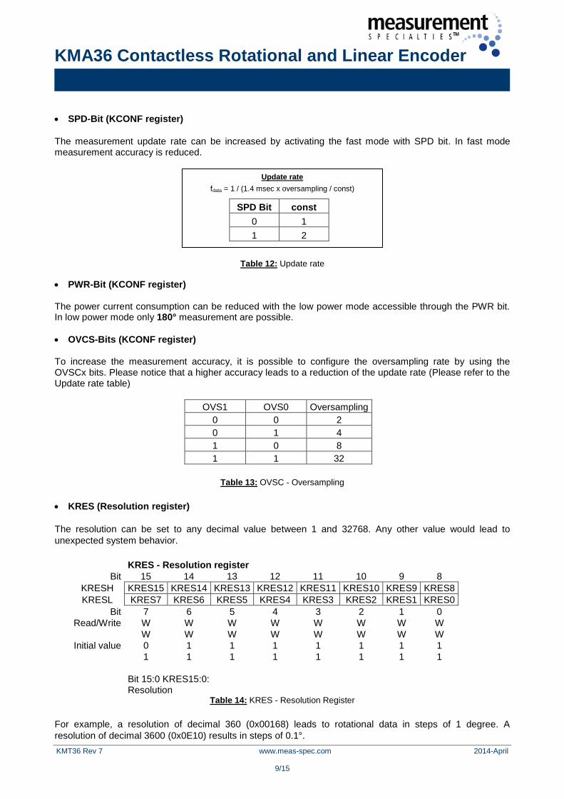
• SPD-Bit (KCONF register) The measurement update rate can be increased by activating the fast mode with SPD bit. In fast mode measurement accuracy is reduced.
Table 12: Update rate
• PWR-Bit (KCONF register) The power current consumption can be reduced with the low power mode accessible through the PWR bit. In low power mode only 180° measurement are possible. • OVCS-Bits (KCONF register) To increase the measurement accuracy, it is possible to configure the oversampling rate by using the OVSCx bits. Please notice that a higher accuracy leads to a reduction of the update rate (Please refer to the Update rate table)
OVS1 OVS0 Oversampling 0 0 2 0 1 4 1 0 8 1 1 32
Table 13: OVSC - Oversampling
• KRES (Resolution register) The resolution can be set to any decimal value between 1 and 32768. Any other value would lead to unexpected system behavior.
KRES - Resolution register
Bit 15 14 13 12 11 10 9 8 KRESH KRES15 KRES14 KRES13 KRES12 KRES11 KRES10 KRES9 KRES8 KRESL KRES7 KRES6 KRES5 KRES4 KRES3 KRES2 KRES1 KRES0
Bit 7 6 5 4 3 2 1 0 Read/Write W W W W W W W W W W W W W W W W Initial value 0 1 1 1 1 1 1 1 1 1 1 1 1 1 1 1
Bit 15:0 KRES15:0: Resolution
Table 14: KRES - Resolution Register
For example, a resolution of decimal 360 (0x00168) leads to rotational data in steps of 1 degree. A resolution of decimal 3600 (0x0E10) results in steps of 0.1°.
Update rate fdata = 1 / (1.4 msec x oversampling / const)
SPD Bit const 0 1 1 2

KMA36 Contactless Rotational and Linear Encoder
KMT36 Rev 7 www.meas-spec.com 2014-April
10/15
HARDWARE CONFIGURATION
The hardware configuration depends on the desired output: two-wire interface or analog. In two-wire interface configuration, the slave address of the system can be configured by connecting A0 and another pin as described in following table.
TWI - Slave address configuration
Address Connection 0x59 A0 GND 0x5A A0 DCOILP 0x5B A0 DCOILN 0x5C A0 DVCC_SE 0x5D A0 VCC
Table 15: TWI / I2C Slave address configuration
In analog mode, the rotation direction can be configured by connecting DVCC_SE and a power supply pin. The user zero reference angle calibration can be activated by connecting A0 and COILP. When the user zero reference angle calibration is active, the next evaluated magnetic angle will be set as the new zero reference angle. The user selectable output voltage for the zero reference angle can be configured by connecting A0 in series with a 4,7k ohm resistor and a port pin. The percentage indicated is relative to the power supply value Vcc and is defined at the zero reference angle position.
ANALOG - Rotation direction configuration Direction Connection
CW DVCC_SE VCC CCW DVCC_SE 4,7K to GND
ANALOG - User selectable output for zero reference
Percent Connection 0% A0 4,7K to VCC
10% A0 4,7K to DVCC_SE 25% A0 4,7K to DCOILN 50% A0 4,7K to GND
ANALOG - Zero reference angle user calibration
Status Connection Active A0 COILP
Inactive A0 -
Table 16: Analog-Mode configuration
KMA36 Contactless Rotational and Linear Encoder
KMT36 Rev 7 www.meas-spec.com 2014-April
11/15
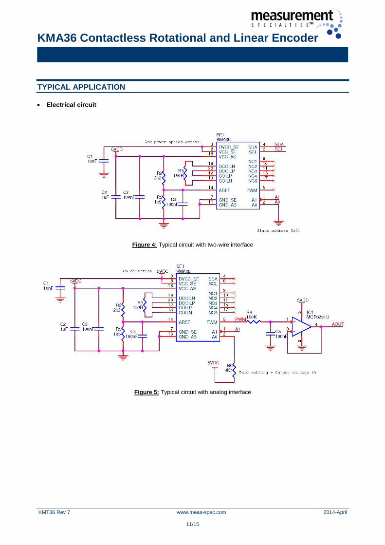
TYPICAL APPLICATION
• Electrical circuit
Figure 4: Typical circuit with two-wire interface
Figure 5: Typical circuit with analog interface
KMA36 Contactless Rotational and Linear Encoder
KMT36 Rev 7 www.meas-spec.com 2014-April
12/15
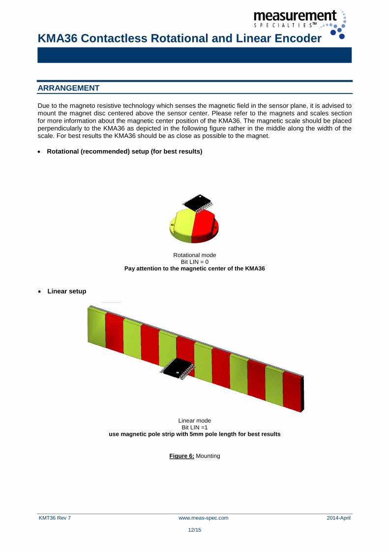
ARRANGEMENT
Due to the magneto resistive technology which senses the magnetic field in the sensor plane, it is advised to mount the magnet disc centered above the sensor center. Please refer to the magnets and scales section for more information about the magnetic center position of the KMA36. The magnetic scale should be placed perpendicularly to the KMA36 as depicted in the following figure rather in the middle along the width of the scale. For best results the KMA36 should be as close as possible to the magnet.
• Rotational (recommended) setup (for best results)
Rotational mode Bit LIN = 0
Pay attention to the magnetic center of the KMA36
• Linear setup
Linear mode
Bit LIN =1 use magnetic pole strip with 5mm pole length for best results
Figure 6: Mounting
KMA36 Contactless Rotational and Linear Encoder
KMT36 Rev 7 www.meas-spec.com 2014-April
13/15
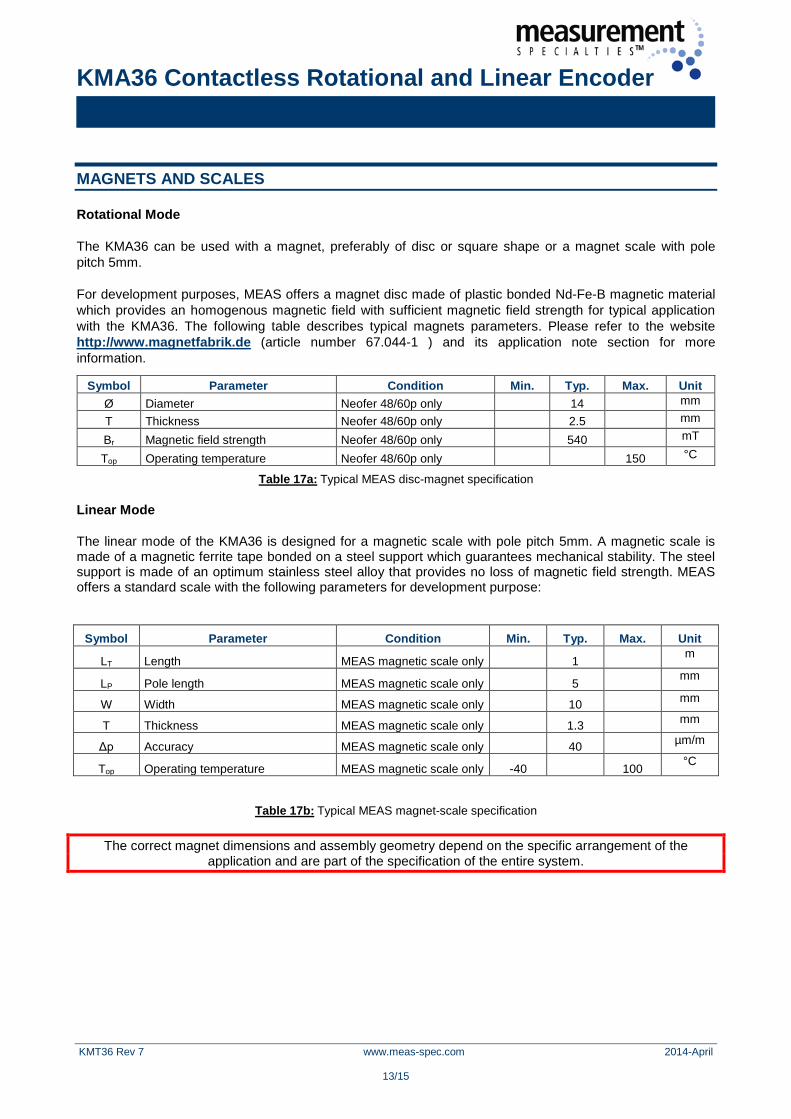
MAGNETS AND SCALES
Rotational Mode
The KMA36 can be used with a magnet, preferably of disc or square shape or a magnet scale with pole pitch 5mm.
For development purposes, MEAS offers a magnet disc made of plastic bonded Nd-Fe-B magnetic material which provides an homogenous magnetic field with sufficient magnetic field strength for typical application with the KMA36. The following table describes typical magnets parameters. Please refer to the website http://www.magnetfabrik.de (article number 67.044-1 ) and its application note section for more information.
Table 17a: Typical MEAS disc-magnet specification
Linear Mode
The linear mode of the KMA36 is designed for a magnetic scale with pole pitch 5mm. A magnetic scale is made of a magnetic ferrite tape bonded on a steel support which guarantees mechanical stability. The steel support is made of an optimum stainless steel alloy that provides no loss of magnetic field strength. MEAS offers a standard scale with the following parameters for development purpose:
Table 17b: Typical MEAS magnet-scale specification
The correct magnet dimensions and assembly geometry depend on the specific arrangement of the application and are part of the specification of the entire system.
Symbol Parameter Condition Min. Typ. Max. Unit Ø Diameter Neofer 48/60p only 14 mm
T Thickness Neofer 48/60p only 2.5 mm
Br Magnetic field strength Neofer 48/60p only 540 mT
Top Operating temperature Neofer 48/60p only 150 °C
Symbol Parameter Condition Min. Typ. Max. Unit
LT Length MEAS magnetic scale only 1 m
LP Pole length MEAS magnetic scale only 5 mm
W Width MEAS magnetic scale only 10 mm
T Thickness MEAS magnetic scale only 1.3 mm
Δp Accuracy MEAS magnetic scale only 40 µm/m
Top Operating temperature MEAS magnetic scale only -40 100 °C

KMA36 Contactless Rotational and Linear Encoder
KMT36 Rev 7 www.meas-spec.com 2014-April
14/15
PACKAGE DRAWING
Figure 7: Package drawing (Magnetic center)
Figure 8: Package drawing

KMA36 Contactless Rotational and Linear Encoder
KMT36 Rev 7 www.meas-spec.com 2014-April
15/15
COMMON DIMENSIONS (MILLIMETERS)
Symbol Min. Typ. Max.
A - - 1.20
A1 0.05 - 0.15
A2 0.80 1.00 1.05
b 0.19 - 0.30
D 6.40 6.50 6.60
E - 6.40 - E1 4.30 4.40 4.50
e - 0.65 -
L 0.45 0.60 0.75
N - 20 -
R 0.09 - -
S 0.20 - -
Table 18: common dimensions
ORDERING CODE
Product Description Article number
KMA36 KMA36 TSSOP20 G-MRMO-031
Table 19: Ordering codes
This data sheet contains data from the preliminary specification. Supplementary data will be published later. Measurement Specialties reserves the right to change the specification without notice, in order to improve the design and performance of the product. ORDERING INFORMATION
NORTH AMERICA EUROPE ASIA
Measurement Specialties, Inc. 1000 Lucas Way
Hampton, VA 23666 United States
Phone: +1-800-745-8008 Fax: +1-757-766-4297
Email: [email protected] Web: www.meas-spec.com
MEAS Deutschland GmbH Hauert 13
D-44227 Dortmund Germany
Phone: +49-(0)231-9740-0 Fax: +49-(0)231-9740-20
Email: [email protected] Web: www.meas-spec.com
Measurement Specialties China Ltd.
No. 26, Langshan Road High-tech Park (North)
Nanshan District, Shenzhen 518057 China
Phone: +86-755-33305088 Fax: +86-755-33305099
Email: [email protected] Web: www.meas-spec.com
The information in this sheet has been carefully reviewed and is believed to be accurate; however, no responsibility is assumed for inaccuracies. Furthermore, this information does not convey to the purchaser of such devices any license under the patent rights to the manufacturer. Measurement Specialties, Inc. reserves the right to make changes without further notice to any product herein. Measurement Specialties, Inc. makes no warranty, representation or guarantee regarding the suitability of its product for any particular purpose, nor does Measurement Specialties, Inc. assume any liability arising out of the application or use of any product or circuit and specifically disclaims any and all liability, including without limitation consequential or incidental damages. Typical parameters can and do vary in different applications. All operating parameters must be validated for each customer application by customer’s technical experts. Measurement Specialties, Inc. does not convey any license under its patent rights nor the rights of others.