K+ K3 K4 - steca-distribution.fr · K1 K2 K3 K4 K+ alle offen all open K+ K2 K3 K4 100% 60% 30% 0 %...
2
Einspeise-Manager StecaGrid SEM Installations- und Bedienungsanleitung Beschreibung Der CE-konforme Einspeise-Manager StecaGrid SEM (SEM) ist eine Schnitt- stelle zwischen einem Rundsteuerempfänger für EEG-konformes Einspeise- Management (RStE) und Steca-Wechselrichtern. Der SEM setzt die Kanalzu- stände K1 ... Kx des Rundsteuerempfängers auf den Steca RS485-Steuerbus um. Vier LEDs zeigen den Status des SEM an. Eine USB-Schnittstelle ermög- licht das Updaten mittels PC und Software StecaGrid User ab Version 3.0. Der SEM wird mit 230 V ~ versorgt. Sicherheit Der SEM darf nur von einer fachkundigen und geschulten Elektrofachkraft installiert werden. Montage Die Installation ist nur in Schaltschränken an einer Tragschiene 35 mm (Hut- schiene) zulässig. Gefahr Die Anschlüsse müssen im Schaltschrank abgedeckt sein. Die Abde- ckung darf nur mit Werkzeug abnehmbar sein. Anschlüsse A1 B1 G1 A2 B2 G2 K+ K1 K2 K3 K4 N L R1+ R1– S0+ S0– SEM USB Kontakt Beschreibung N Nullleiter L Phasenleiter R1+, R1– z. Zt. ohne Funktion S0+, S0– z. Zt. ohne Funktion SEM z. Zt. ohne Funktion A1, B1, G1 RS485-Bus zu den Wechselrichtern A2, B2, G2 z. Zt. ohne Funktion K+ Spannungsversorgung für die Relais-Kontakte des RStE K1 ... K4 Eingänge für Steuersignale vom RStE USB virtuelle, serielle PC-Schnittstelle Anschluss des Rundsteuerempfängers Achtung Die Spannungsversorgung für K1 ... K4 muss durch K+ erfolgen. 100 % 0 % 30 % 60 % K4 K3 K2 K1 K+ alle offen all open K4 K3 K2 K+ 100 % 0 % 30 % 60 % K+ K3 K2 100 % 0 % 30 % 60 % alle offen all open alle geschlossen all closed 70 % 1) K4 K3 K+ = Rundsteuerempfänger 1) 70 % = Festwert Wartung Der SEM ist wartungsfrei. Bei Bedarf wie folgt reinigen. Gefahr Lebensgefahr durch Stromschlag! Gerät nur im spannungslosen Zustand reinigen. Gerät mit einem trockenen oder nebelfeuchten Tuch reinigen (2%ige Kernseifelösung möglich; Seifenreste entfernen). Gewährleistung Die Garantiezeit beträgt 5 Jahre. Mehr dazu unter www.steca.com/service. Technische Daten Charakterisierung des Betriebsverhaltens Eigenverbrauch < 3 W Einsatzbedingungen Einsatzgebiet klimatisiert in Innenräumen, nicht klimatisiert in Innenräumen Schnittstelle zum Wechselrichter Steca RS485-Bus mit max. 1.000 m Kabellänge Umgebungstempe- ratur Betrieb: –15 °C ... +60 °C Lagerung: –40 °C ... +85 °C Relative Feuchte 0 % ... 95 % Geräuschemission geräuschlos Ausstattung und Ausführung Schutzart IP 20 Schutzklasse II Anschlussklemmen (fein-/einzeldrahtig) 1,5 mm 2 / 2,5 mm 2 Abmessungen 91 x 72 x 58 mm Gewicht 300 g Stromversorgung 230 V ~ / 50 Hz oder 60 Hz Schnittstellen RStE-Kanäle 1) 2, 3 oder 4 Kanäle (K1 ... K4) RS485-Bus 1) 1x, RJ45, SEM = Master für ≤ 10x Slave Steca Grid 1800 ... 4200/8000+/10000+ 1x, RJ45, SEM = Slave für Datenlogger Solar Log, MeteoControl S0 1) z. Zt. keine Funktion Relais z. Zt. keine Funktion USB 1) 1x, Typ B, Schnittstelle zu Software Ste- caGrid User (http://www.steca.com/ stecagrid_user), mitgeliefertes USB-Kabel: Typ A ↔ B, 1 m LEDs Power (grün) Ein: kein Fehler Aus: Stromversorgung fehlt Switch (grün) z. Zt. keine Funktion Limit (gelb) Ein: Wechselrichterleistung ist reduziert Aus: Volleinspeisung Error (rot) Ein: Kanalzuordnung K1 ... Kx ungültig Bus- kommunikation gestört Aus: kein Fehler Prüfbescheinigung CE-Zeichen: www.steca.com/sem 1) SELV Kontakt Europa Steca Elektronik GmbH Mammostraße 1 87700 Memmingen Germany Fon: +49 700 STECAGRID +49 (0) 700 783 224 743 Mo. bis Fr. von 8:00 bis 16:00 12 ct/Min. aus d. dt. Festnetz Fax: +49 (0) 8331 8558 132 E-Mail: [email protected] Internet: www.stecasolar.com DE 747.232 | Z01 | 2013-04-17
Transcript of K+ K3 K4 - steca-distribution.fr · K1 K2 K3 K4 K+ alle offen all open K+ K2 K3 K4 100% 60% 30% 0 %...
Einspeise-Manager StecaGrid SEMInstallations- und Bedienungsanleitung
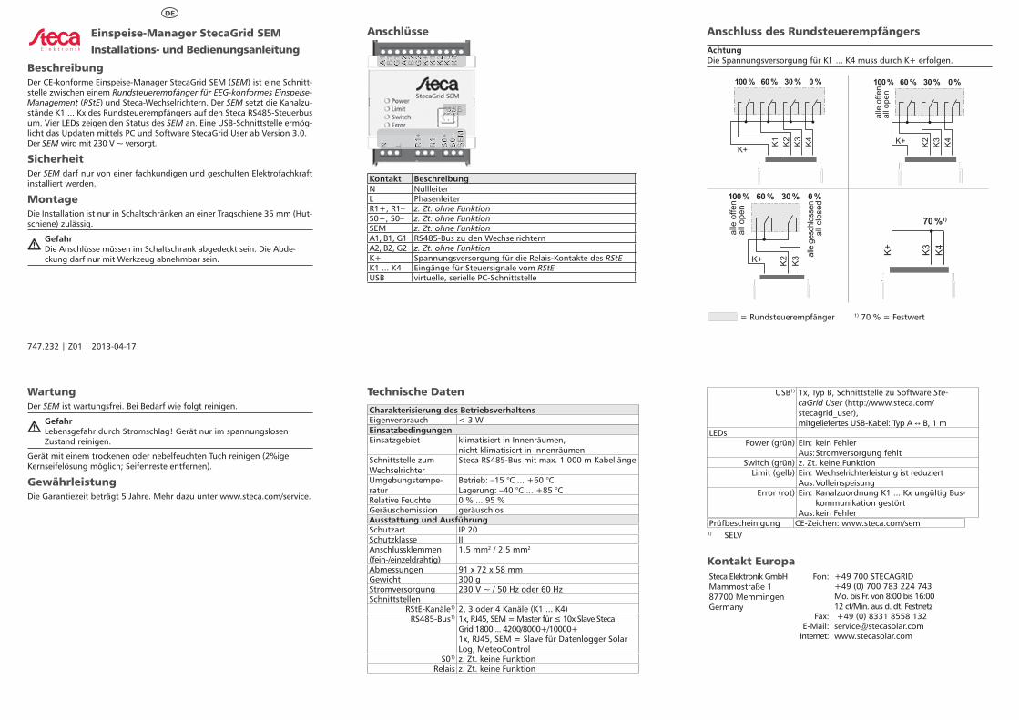
BeschreibungDer CE-konforme Einspeise-Manager StecaGrid SEM (SEM) ist eine Schnitt-stelle zwischen einem Rundsteuerempfänger für EEG-konformes Einspeise-Management (RStE) und Steca-Wechselrichtern. Der SEM setzt die Kanalzu-stände K1 ... Kx des Rundsteuerempfängers auf den Steca RS485-Steuerbus um. Vier LEDs zeigen den Status des SEM an. Eine USB-Schnittstelle ermög-licht das Updaten mittels PC und Software Steca Grid User ab Version 3.0. Der SEM wird mit 230 V ~ versorgt.
SicherheitDer SEM darf nur von einer fachkundigen und geschulten Elektrofachkraft installiert werden.
MontageDie Installation ist nur in Schaltschränken an einer Tragschiene 35 mm (Hut-schiene) zulässig.
Gefahr Die Anschlüsse müssen im Schaltschrank abgedeckt sein. Die Abde-
ckung darf nur mit Werkzeug abnehmbar sein.
Anschlüsse
A1
B1
G1
A2
B2
G2
K+ K1
K2
K3
K4
N L R1+
R1–
S0+
S0–
SEM
USB
Kontakt BeschreibungN NullleiterL PhasenleiterR1+, R1– z. Zt. ohne FunktionS0+, S0– z. Zt. ohne FunktionSEM z. Zt. ohne FunktionA1, B1, G1 RS485-Bus zu den WechselrichternA2, B2, G2 z. Zt. ohne FunktionK+ Spannungsversorgung für die Relais-Kontakte des RStEK1 ... K4 Eingänge für Steuersignale vom RStEUSB virtuelle, serielle PC-Schnittstelle
Anschluss des Rundsteuerempfängers
AchtungDie Spannungsversorgung für K1 ... K4 muss durch K+ erfolgen.
100 % 0 %30 %60 %
K4K3K2K1K+
alle
offe
nal
l ope
n
K4K3K2K+
100 % 0 %30 %60 %
K+ K3K2
100 % 0 %30 %60 %
alle
offe
nal
l ope
n
alle
gesc
hloss
enal
l clo
sed
70 %1)
K4K3K+
= Rundsteuerempfänger 1) 70 % = Festwert
WartungDer SEM ist wartungsfrei. Bei Bedarf wie folgt reinigen.
Gefahr Lebensgefahr durch Stromschlag! Gerät nur im spannungslosen
Zustand reinigen.
Gerät mit einem trockenen oder nebelfeuchten Tuch reinigen (2%ige Kernseifelösung möglich; Seifenreste entfernen).
GewährleistungDie Garantiezeit beträgt 5 Jahre. Mehr dazu unter www.steca.com/service.
Technische Daten
Charakterisierung des BetriebsverhaltensEigenverbrauch < 3 WEinsatzbedingungenEinsatzgebiet klimatisiert in Innenräumen,
nicht klimatisiert in InnenräumenSchnittstelle zum Wechselrichter
Steca RS485-Bus mit max. 1.000 m Kabellänge
Umgebungstempe-ratur
Betrieb: –15 °C ... +60 °CLagerung: –40 °C ... +85 °C
Relative Feuchte 0 % ... 95 %Geräuschemission geräuschlosAusstattung und AusführungSchutzart IP 20Schutzklasse IIAnschlussklemmen (fein-/einzeldrahtig)
1,5 mm2 / 2,5 mm2
Abmessungen 91 x 72 x 58 mmGewicht 300 gStromversorgung 230 V ~ / 50 Hz oder 60 HzSchnittstellen
RStE-Kanäle1) 2, 3 oder 4 Kanäle (K1 ... K4)RS485-Bus1) 1x, RJ45, SEM = Master für ≤ 10x Slave Steca
Grid 1800 ... 4200/8000+/10000+1x, RJ45, SEM = Slave für Datenlogger Solar Log, Meteo Control
S01) z. Zt. keine FunktionRelais z. Zt. keine Funktion
USB1) 1x, Typ B, Schnittstelle zu Software Ste-caGrid User (http:// www.steca.com/ stecagrid_user), mitgeliefertes USB-Kabel: Typ A ↔ B, 1 m
LEDsPower (grün) Ein: kein Fehler
Aus: Stromversorgung fehltSwitch (grün) z. Zt. keine Funktion
Limit (gelb) Ein: Wechselrichterleistung ist reduziertAus: Volleinspeisung
Error (rot) Ein: Kanalzuordnung K1 ... Kx ungültig Bus-kommunikation gestört
Aus: kein FehlerPrüfbescheinigung CE-Zeichen: www.steca.com/sem
1) SELV
Kontakt EuropaSteca Elektronik GmbHMammostraße 187700 MemmingenGermany
Fon: +49 700 STECAGRID+49 (0) 700 783 224 743Mo. bis Fr. von 8:00 bis 16:00 12 ct/Min. aus d. dt. Festnetz
Fax: +49 (0) 8331 8558 132E-Mail: [email protected]
Internet: www.stecasolar.com
DE
747.232 | Z01 | 2013-04-17
StecaGrid SEM feed-in managerInstallation and operating instructions
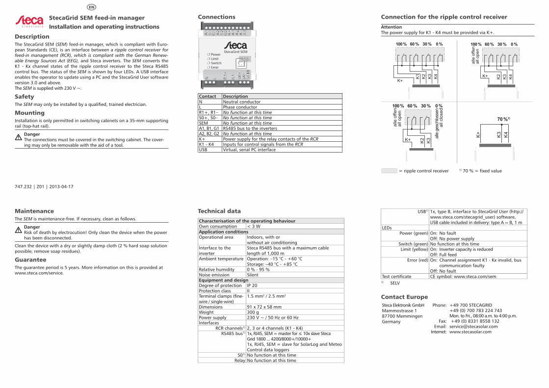
DescriptionThe StecaGrid SEM (SEM) feed-in manager, which is compliant with Euro-pean Standards (CE), is an interface between a ripple control receiver for feed-in management (RCR), which is compliant with the German Renew-able Energy Sources Act (EEG), and Steca inverters. The SEM converts the K1 - Kx channel states of the ripple control receiver to the Steca RS485 control bus. The status of the SEM is shown by four LEDs. A USB interface enables the operator to update using a PC and the StecaGrid User software version 3.0 and above.The SEM is supplied with 230 V ~.
SafetyThe SEM may only be installed by a qualified, trained electrician.
MountingInstallation is only permitted in switching cabinets on a 35-mm supporting rail (top-hat rail).
Danger The connections must be covered in the switching cabinet. The cover-
ing may only be removable with the aid of a tool.
Connections
A1
B1
G1
A2
B2
G2
K+ K1
K2
K3
K4
N L R1+
R1–
S0+
S0–
SEM
USB
Contact DescriptionN Neutral conductorL Phase conductorR1+, R1– No function at this timeS0+, S0– No function at this timeSEM No function at this timeA1, B1, G1 RS485 bus to the invertersA2, B2, G2 No function at this timeK+ Power supply for the relay contacts of the RCRK1 - K4 Inputs for control signals from the RCRUSB Virtual, serial PC interface
Connection for the ripple control receiver
AttentionThe power supply for K1 - K4 must be provided via K+.
100 % 0 %30 %60 %
K4K3K2K1K+
alle
offe
nal
l ope
n
K4K3K2K+
100 % 0 %30 %60 %
K+ K3K2
100 % 0 %30 %60 %
alle
offe
nal
l ope
n
alle
gesc
hloss
enal
l clo
sed
70 %1)
K4K3K+
= ripple control receiver 1) 70 % = fixed value
MaintenanceThe SEM is maintenance-free. If necessary, clean as follows.
Danger Risk of death by electrocution! Only clean the device when the power
has been disconnected.
Clean the device with a dry or slightly damp cloth (2 % hard soap solution possible; remove soap residues).
GuaranteeThe guarantee period is 5 years. More information on this is provided at www.steca.com/service.
Technical data
Characterisation of the operating behaviourOwn consumption < 3 WApplication conditionsOperational area Indoors, with or
without air conditioningInterface to the inverter
Steca RS485 bus with a maximum cable length of 1,000 m
Ambient temperature Operation: –15 °C - +60 °CStorage: –40 °C - +85 °C
Relative humidity 0 % - 95 %Noise emission SilentEquipment and designDegree of protection IP 20Protection class IITerminal clamps (fine-wire / single-wire)
1.5 mm2 / 2.5 mm2
Dimensions 91 x 72 x 58 mmWeight 300 gPower supply 230 V ~ / 50 Hz or 60 HzInterfaces
RCR channels1) 2, 3 or 4 channels (K1 - K4)RS485 bus1) 1x, RJ45, SEM = master for ≤ 10x slave Steca
Grid 1800 ... 4200/8000+/10000+1x, RJ45, SEM = slave for Solar Log and Meteo Control data loggers
S01) No function at this timeRelay No function at this time
USB1) 1x, type B, interface to StecaGrid User (http:// www.steca.com/ stecagrid_user) software, USB cable included in delivery: type A ↔ B, 1 m
LEDsPower (green) On: No fault
Off: No power supplySwitch (green) No function at this timeLimit (yellow) On: Inverter capacity is reduced
Off: Full feedError (red) On: Channel assignment K1 - Kx invalid, bus
communication faultyOff: No fault
Test certificate CE symbol: www.steca.com/sem1) SELV
Contact EuropeSteca Elektronik GmbHMammostrasse 187700 MemmingenGermany
Phone: +49 700 STECAGRID+49 (0) 700 783 224 743Mon. to Fri., 08:00 a.m. to 4:00 p.m.
Fax: +49 (0) 8331 8558 132Email: [email protected]
Internet: www.stecasolar.com
EN
747.232 | Z01 | 2013-04-17