July 2003© Peter Komisarczuk, VUW, 2003 Supplement 1 Ethernet LAN Technology Peter Komisarczuk...
58
July 2003 © Peter Komisarczuk, VUW, 2003 Supplement 1 Ethernet LAN Technology Peter Komisarczuk Material used here is from various sources: A Tanenbaum, Computer Networks, 4 th Edition W. Stallings, Data and Computer Communications, 6 th Edition Various web sources of information from Nortel Networks and Cisco Systems -- NTUST ( 加加 加加加加 --- 加加加 加加加加 / ) -2008Q2 ( 斜 斜斜斜 体 --- 斜斜斜斜斜斜 斜斜斜斜斜斜 , )- 04/14/2008
-
Upload
randell-matthews -
Category
Documents
-
view
214 -
download
0
Transcript of July 2003© Peter Komisarczuk, VUW, 2003 Supplement 1 Ethernet LAN Technology Peter Komisarczuk...

July 2003© Peter Komisarczuk, VUW, 2003
Supplement 1 Ethernet LAN Technology
Peter KomisarczukMaterial used here is from various sources:A Tanenbaum, Computer Networks, 4th EditionW. Stallings, Data and Computer Communications, 6th EditionVarious web sources of information from Nortel Networks and Cisco Systems-- NTUST ( 加註 紅大標題 --- 大哉問/考題型式 ) -2008Q2( 斜体的紅頁 --- 期中考暫不考,列入期末範圍 )- 04/14/2008

July 2003© Peter Komisarczuk, VUW, 2003
Corporate Overview
Corporate Local Area
NetworkHost-A
Host-B
Host-E
Host-D
Host-C
Corporate LAN
Corporate LAN
Internet Service Provider
StorageArea Network FC switch
Mainframe Storage Arrays
Storage
(Raid array/JBOD)
Servers
Tape
Router
IP based networkspredominate the LAN ……..
July 2003© Peter Komisarczuk, VUW, 2003
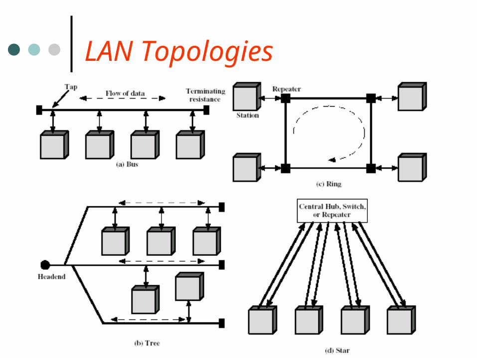
LAN Topologies
July 2003© Peter Komisarczuk, VUW, 2003
MAC Types
Defined by the topology the protocol must support LANs usually share the “medium” between a number of hosts
Most architectures could use either centralised or distributed control mechanisms Centralised:
• Good “access” control (e.g. not a recognised address)• Easy support of traffic priority, capacity and capability to override
normal operations • Simplifies the control logic (protocol) required at the controlled stations• Problem: Centralised controller is a potential single point of failure • Centralised controller is a potential bottleneck therefore reducing
throughput and increased response time Decentralised:
• Avoids single point of failure, but requires complex per node logic

July 2003© Peter Komisarczuk, VUW, 2003
MAC Types Defined by their “access” mechanism
Round Robin – one station at a time is given permission to transmit on the medium (e.g. by holding the “token”)
• This can be for an upper bound of time t or • by a defined number of frames: single or multiple frames, the time
between stations transmitting is based on maximum frame size Reservation – “time slots” are allocated to stations dependent
on • the type of source traffic (i.e. is it periodic, how much volume, time
constraints – e.g. end-to-end delay, jitter tolerance of the receiver) Contention – the access to the medium is not highly
controlled – works on statistics (e.g. CSMA/CD and various LAN and satellite variants)
(Defined by their signal – baseband or broadband)
July 2003© Peter Komisarczuk, VUW, 2003
Line Encoding
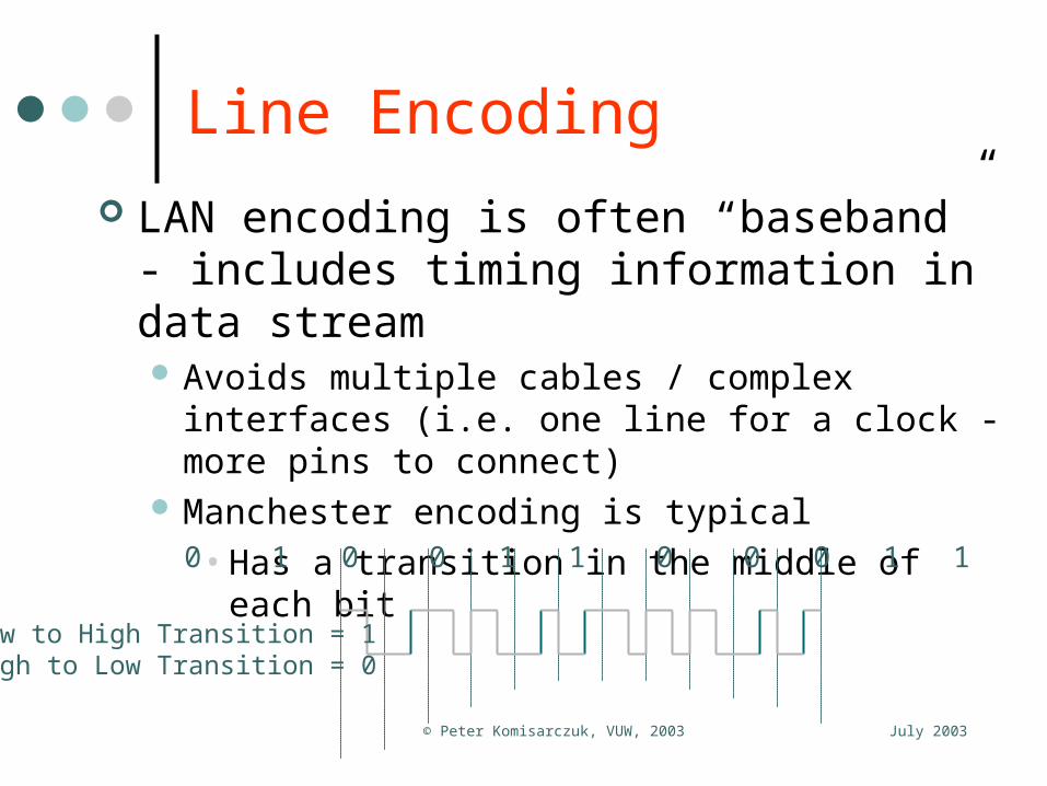
LAN encoding is often “baseband” - includes timing information in data stream Avoids multiple cables / complex interfaces (i.e. one
line for a clock - more pins to connect) Manchester encoding is typical
• Has a transition in the middle of each bit
0 1 0 0 1 1 0 0 0 1 1
Low to High Transition = 1High to Low Transition = 0

July 2003© Peter Komisarczuk, VUW, 2003
LAN Characteristics Typically a < 1 where a = Tp/Tf
Propagation delay Tp ? • For a speed of propagation = 2x10⁸ meters per seconds, what is the
Tp for a network of 1km and 2.5km? Frame transmit time, Tf ? Minimum Ethernet frame size is 72 bytes
• At 10Mbps how long does it take to transmit a minimum frame? Max Ethernet frame size is 1518 bytes (1500 bytes data)
• How long does it take to transmit a maximum sized frame? “a” is dependent on Transmission Speed (bps) so how does “a”
change for different Ethernet transmission speeds? What is the typical Tf (Transmission delay) and ratio “a” at:
• 10Mbps ? 100Mbps ? 1Gbps ? 10Gbps ?• What value of frame size did you choose?
July 2003© Peter Komisarczuk, VUW, 2003
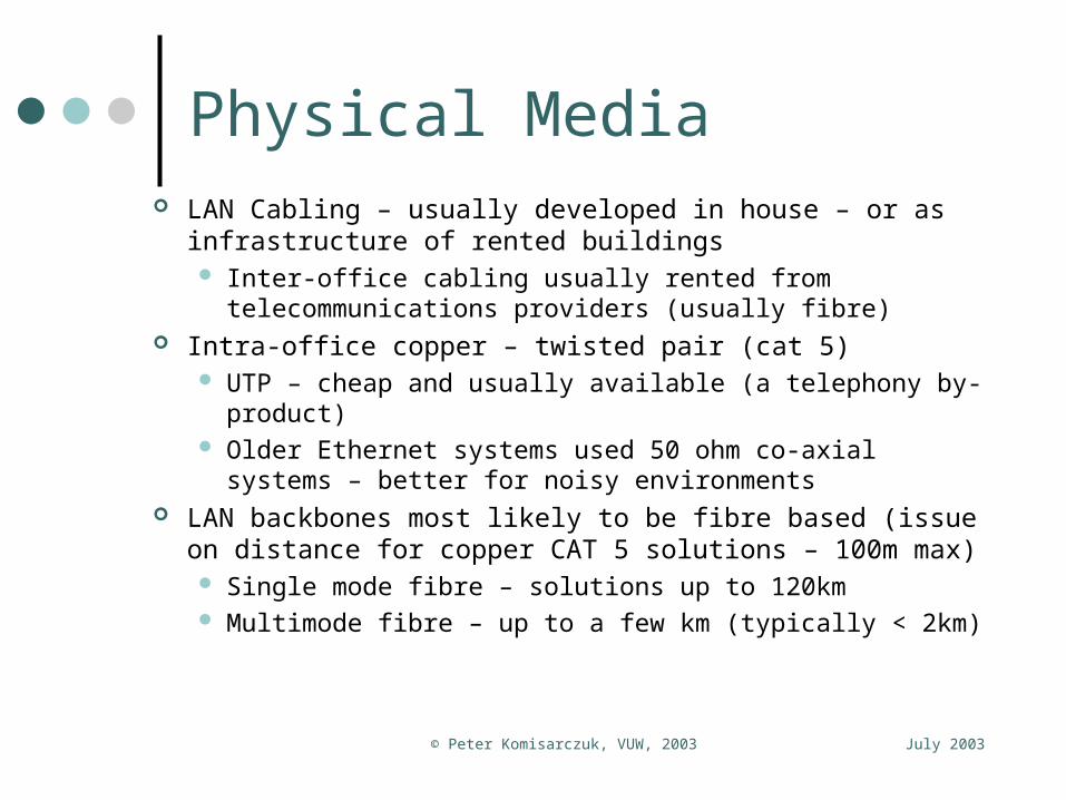
Physical Media LAN Cabling – usually developed in house – or as
infrastructure of rented buildings Inter-office cabling usually rented from telecommunications
providers (usually fibre) Intra-office copper – twisted pair (cat 5)
UTP – cheap and usually available (a telephony by-product) Older Ethernet systems used 50 ohm co-axial systems –
better for noisy environments LAN backbones most likely to be fibre based (issue on
distance for copper CAT 5 solutions – 100m max) Single mode fibre – solutions up to 120km Multimode fibre – up to a few km (typically < 2km)

July 2003© Peter Komisarczuk, VUW, 2003
Communication Reference Models
presentation
application
session
transport
network
data link
physical
OSIapplication
transport
internet
host tonetwork
TCP/IP
not present
tcp (connection) udp (connectionless)
ip (routes between networks)
smtp (email), http (web), ftp
IEEE 802.* Frame Relay, ATMFibre, copper (DSL)
HDLC

July 2003© Peter Komisarczuk, VUW, 2003
The LAN Protocol Stack IEEE produce(d) many
LAN standards Broke down link layer
into two sublayers: MAC (media/physical
and topology dependent) LLC (media and topology
independent) Followed ISO model
Our current study is limited to the LLC layer and below
July 2003© Peter Komisarczuk, VUW, 2003
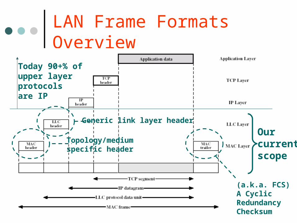
LAN Frame Formats Overview
Ourcurrentscope
Today 90+% ofupper layer protocolsare IP
(a.k.a. FCS)A CyclicRedundancyChecksum
Generic link layer header
Topology/medium specific header
July 2003© Peter Komisarczuk, VUW, 2003
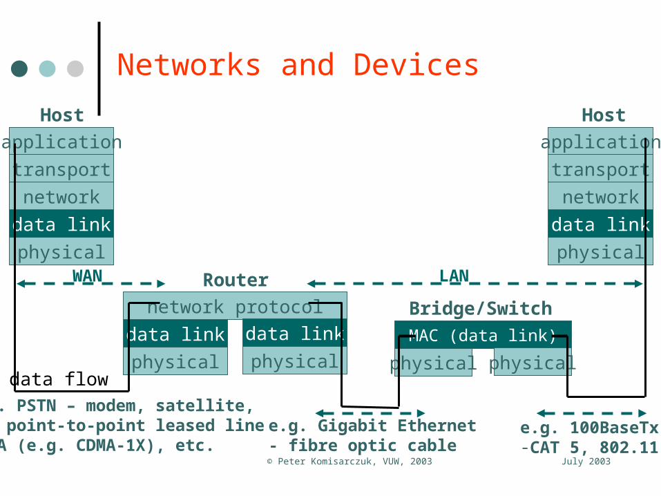
Networks and Devices
application
transport
network
data link
physical
Host
application
transport
network
data link
physical
Host
network protocol
data link
physical
Router
data link
physicaldata flow
MAC (data link)
physical
Bridge/Switch
physical
WAN LAN
e.g. Gigabit Ethernet- fibre optic cable
e.g. 100BaseTx-CAT 5, 802.11
e.g. PSTN – modem, satellite, TDM point-to-point leased lineCDMA (e.g. CDMA-1X), etc.
July 2003© Peter Komisarczuk, VUW, 2003
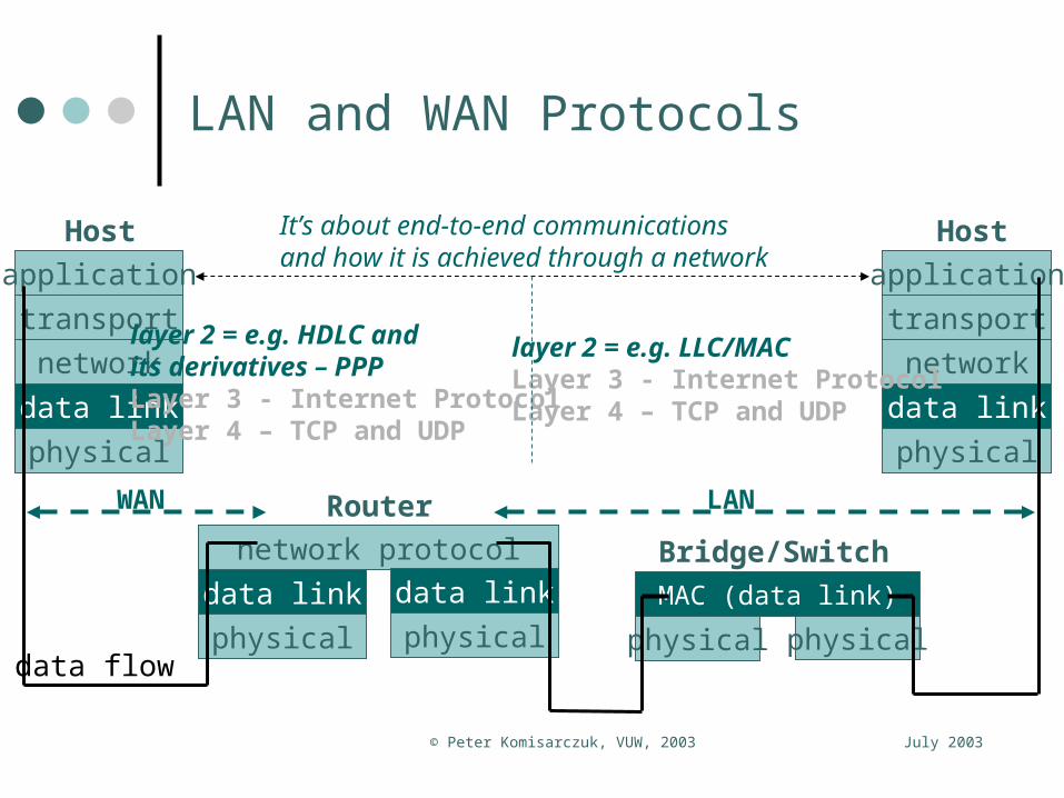
LAN and WAN Protocols
network protocol
data link
physical
Router
data link
physical
application
transport
network
data link
physical
Host
application
transport
network
data link
physical
Host
data flow
MAC (data link)
physical
Bridge/Switch
physical
WAN LAN
layer 2 = e.g. HDLC and its derivatives – PPPLayer 3 - Internet ProtocolLayer 4 – TCP and UDP
layer 2 = e.g. LLC/MACLayer 3 - Internet ProtocolLayer 4 – TCP and UDP
It’s about end-to-end communicationsand how it is achieved through a network

July 2003© Peter Komisarczuk, VUW, 2003
Ethernet Media
- options for different twisted pair types (UTP CAT 3/5, STP)- also point-to-point fibre optic connections (multimode/mono mode)
July 2003© Peter Komisarczuk, VUW, 2003
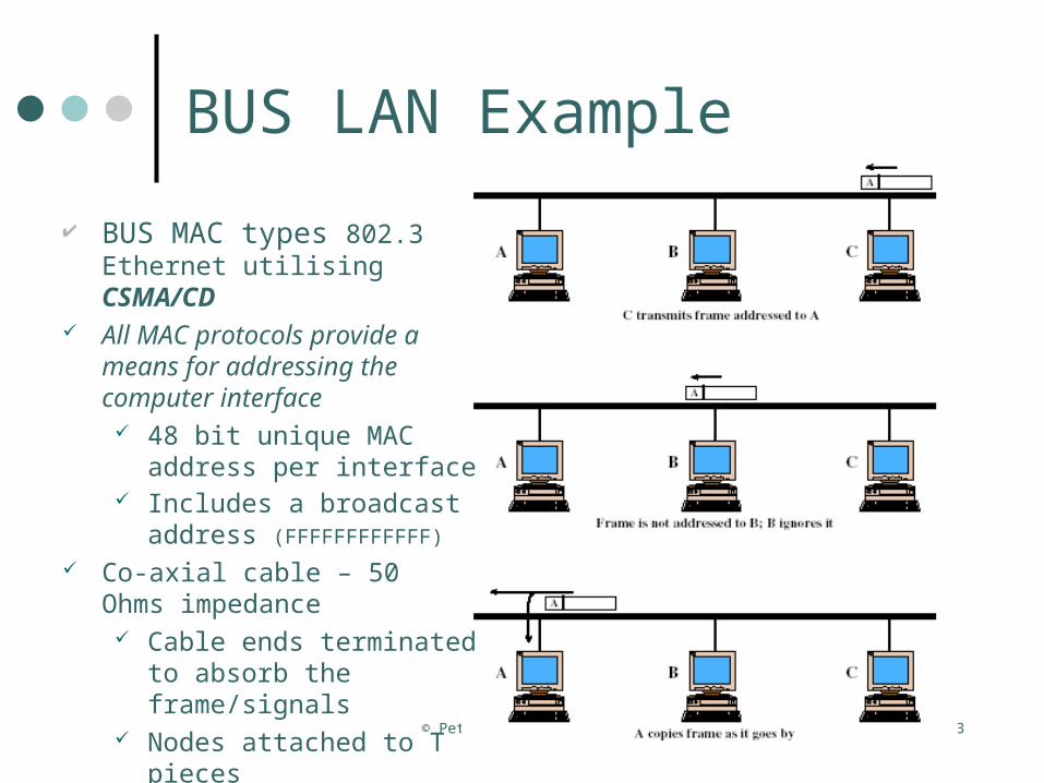
BUS LAN Example
BUS MAC types 802.3 Ethernet utilising CSMA/CD
All MAC protocols provide a means for addressing the computer interface 48 bit unique MAC address
per interface Includes a broadcast
address (FFFFFFFFFFFF)
Co-axial cable – 50 Ohms impedance Cable ends terminated to
absorb the frame/signals Nodes attached to T pieces
July 2003© Peter Komisarczuk, VUW, 2003
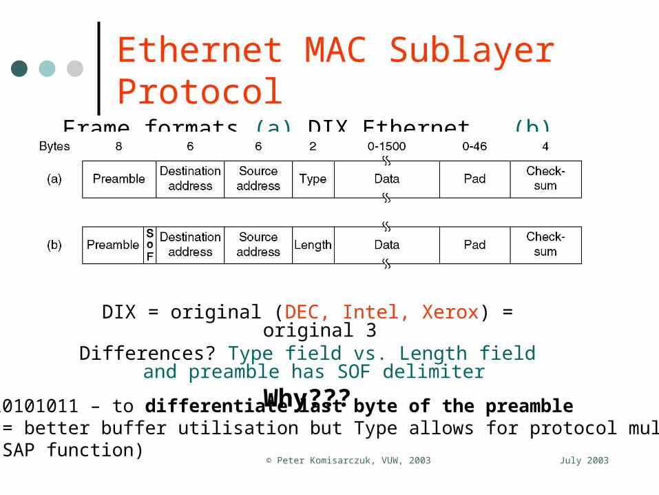
Ethernet MAC Sublayer Protocol
Frame formats (a) DIX Ethernet, (b) IEEE 802.3.
DIX = original (DEC, Intel, Xerox) = original 3Differences? Type field vs. Length field and preamble has
SOF delimiter
Why???SOF = 10101011 – to differentiate last byte of the preambleLength = better buffer utilisation but Type allows for protocol multiplexing(a LLC SAP function)

July 2003© Peter Komisarczuk, VUW, 2003
Collision Detection
Carrier SenseMultiple Accessw/ Collision Detection(CSMA/CD)
Based on radio/satelliteprotocols - aloha and slotted aloha
CSMA/CD has betterutilisation because ofsmall collision window(51.2 microseconds)

July 2003© Peter Komisarczuk, VUW, 2003
Binary Exponential Backoff!
Dynamically adapts to the number of stations trying to send Collision window based – determined by engineering of
original Ethernet as 2*max propagation delay on a max sized Ethernet network
Initial collision – backoff 0 or 1 collision windows. Each station chooses a random value “0” or “1”
If they collide again the random number is doubled and stations choose values, 0, 1 or 2
If a collision takes place again the the random variable is doubled again, and so on
The maximum backoff time is 1023*collision window If after 16 attempts the stations cannot get a packet through
they give up! The network congestion error is reported back up the protocol stack in the station(s)

July 2003© Peter Komisarczuk, VUW, 2003
Multiple LAN Segments - Repeaters
Bus segments - joined by repeaters Max thin co-axial cable run is
185m (approx 200m!) Max thick co-axial cable run
is 500m Repeater forwards a frame
from one segment to the other (is bidirectional)
Repeater regenerates clock but is otherwise transparent (small delay)
CSMA/CD operates over the whole network
Network “span” is between 1000 and 2500m => up to 5 segments can be connected
10Mbps(10Base2)
10Mbps(10Base5)
10Mbps(10Base2)

July 2003© Peter Komisarczuk, VUW, 2003
Ethernet Performance
Efficiency of Ethernet at 10 Mbps with 512-bit slot time (51.2μs).
See the discussionin W Stallings 6/eAppendix 14B“PerformanceIssues”This picture is taken from A Tanembaum 4/e, Computer Networksto emphasise characteristic

July 2003© Peter Komisarczuk, VUW, 2003
Shared Medium Hub
10 Mbps The shared busis collapsed intothe hub backplane
Shared medium hub is similar to a A collapsed bus Works at one
speed (e.g. 10Mbps)
“Same” collision characteristics
Benefits: Makes use of
CAT 5 cabling Can be made to
switch off a station that is misbehaving

July 2003© Peter Komisarczuk, VUW, 2003
Hub LAN Architecture
The driver for hub LANs – using existing unshielded twisted pair for cheapestpossible LAN solution
StandardTelephonyCat 5 UTP
Typically 4 wire,Tx pair and a Rx pair – full duplex?
Source: W Stallings, 6th Edition
Issue: we are just creating a large broadcast domain – high probability of collisions
Solutions?

July 2003© Peter Komisarczuk, VUW, 2003
Segmenting Ethernet Networks: LAN Bridging Basics
A bridge is a MAC layer device that interconnects 2 or more LAN segments (usually of the same MAC type)
Stallings gives 4 reasons for using a bridge: Reliability of a LAN network is increased – any single error no
longer affects the whole network Performance of a single large LAN is improved by clustering
related devices onto a single LAN segment such that inter-LAN traffic is minimised
• Reduces collision domain in IEEE 802.3• Minimises token rotation time in IEEE 802.5
Security – different concerns within an organisation can be physically separated by bridges and inter LAN communications limited
Geography – sites within an organisation can be linked with remote bridges to create one larger LAN

July 2003© Peter Komisarczuk, VUW, 2003
Basic Learning Bridge Operation
July 2003© Peter Komisarczuk, VUW, 2003
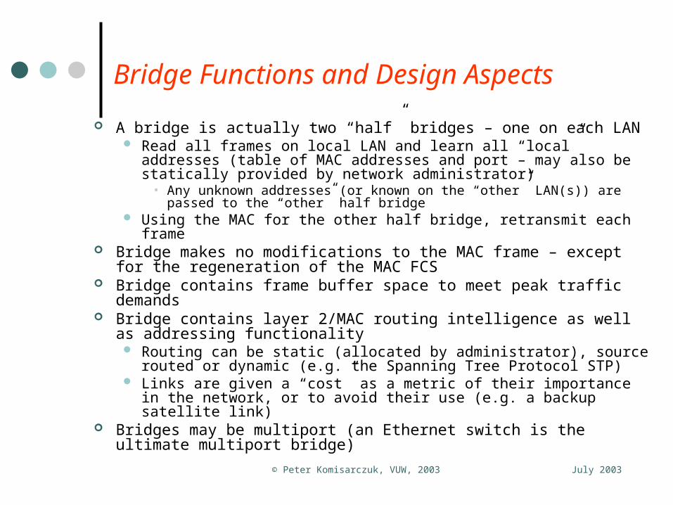
Bridge Functions and Design Aspects
A bridge is actually two “half” bridges – one on each LAN Read all frames on local LAN and learn all “local” addresses (table
of MAC addresses and port – may also be statically provided by network administrator)
• Any unknown addresses (or known on the “other” LAN(s)) are passed to the “other” half bridge
Using the MAC for the other half bridge, retransmit each frame Bridge makes no modifications to the MAC frame – except for the
regeneration of the MAC FCS Bridge contains frame buffer space to meet peak traffic demands Bridge contains layer 2/MAC routing intelligence as well as
addressing functionality Routing can be static (allocated by administrator), source routed or
dynamic (e.g. the Spanning Tree Protocol STP) Links are given a “cost” as a metric of their importance in the
network, or to avoid their use (e.g. a backup satellite link) Bridges may be multiport (an Ethernet switch is the ultimate
multiport bridge)
July 2003© Peter Komisarczuk, VUW, 2003
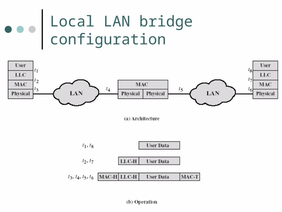
Local LAN bridge configuration

July 2003© Peter Komisarczuk, VUW, 2003
Remote LAN bridge configuration
WANMAC PPPPhy. Phy.
PPP MACPhy. Phy.
t4 t5
E.g. E1 or T1 leased line
t1 t8
t2 t7
t3 t6
t4 t5
User Data
User DataLLC-H
User DataLLC-HMAC-H MAC-T
User DataLLC-HMAC-H MAC-TPPP-H PPP-T

July 2003© Peter Komisarczuk, VUW, 2003
W Stallings example network Note LAN B and C are
just to connect bridges Look at some sample
frame routes ……… There is one network
loop in the network – where is it?
There are two mechanisms to overcome network loops
LAN Example

July 2003© Peter Komisarczuk, VUW, 2003
Without The Spanning Tree Algorithm or a Static Routing Table
Station A sends a frame to Station B Both bridges learn
A is on LAN X Both bridges Tx
frame on LAN Y Station B receives
2 copies of the frame
Both bridges see a frame from A on LAN Y and learn A is on Y
Result: station ABecomes unreachable from LAN Y
July 2003© Peter Komisarczuk, VUW, 2003
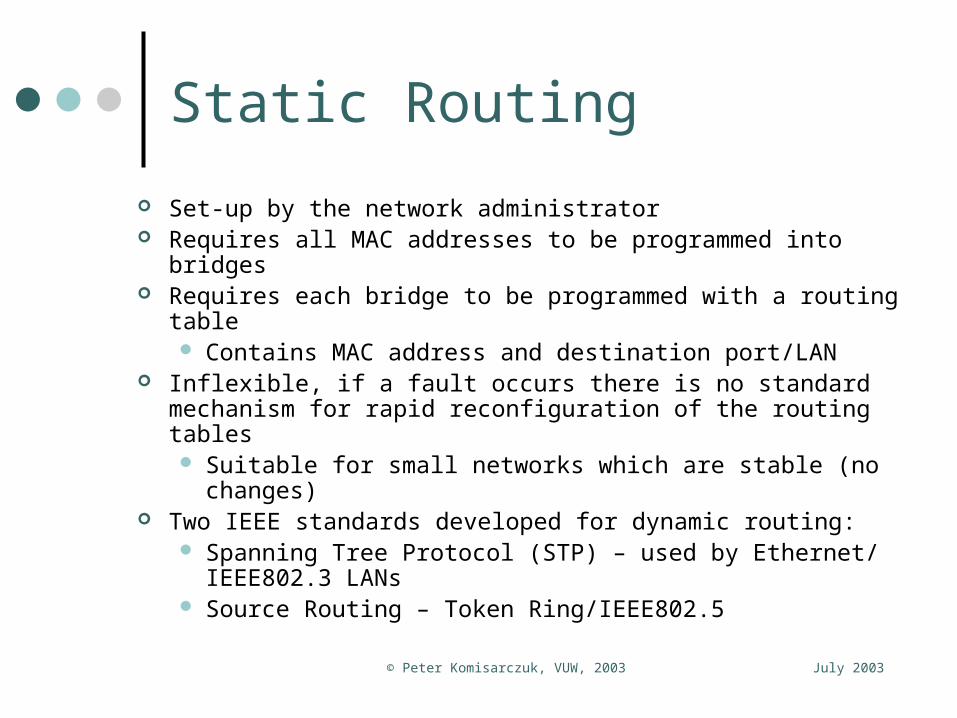
Static Routing
Set-up by the network administrator Requires all MAC addresses to be programmed into bridges Requires each bridge to be programmed with a routing table
Contains MAC address and destination port/LAN Inflexible, if a fault occurs there is no standard mechanism for
rapid reconfiguration of the routing tables Suitable for small networks which are stable (no changes)
Two IEEE standards developed for dynamic routing: Spanning Tree Protocol (STP) – used by Ethernet/
IEEE802.3 LANs Source Routing – Token Ring/IEEE802.5

July 2003© Peter Komisarczuk, VUW, 2003
Spanning Tree Protocol (STP) Algorithm consists of three mechanisms:
Address Learning• Use source MAC address field in each frame• Frame has come from the LAN on which it was received (i.e.a
port on the bridge)• To adapt to reconfiguration of the network each address has a
timer. When timer expires the address is removed from the database
Frame Forwarding• Forwarding database is created for each port attached to a LAN• A frame with matching destination address is forwarded through
the port (if port is not disabled by Spanning Tree Algorithm)• If address is unknown forward frame to all other active ports
except for the port the frame came in on Spanning Tree Algorithm ………

July 2003© Peter Komisarczuk, VUW, 2003
Spanning Tree Algorithm Based on graph theory: nodes (LANs) and edges (bridges)
For any connected graph there is a spanning tree of edges connecting pairs of nodes, that maintains the connectivity of the graph but contains no closed loops
One bridge is selected as route (can be set by network administrator, or use unique numbers burned into each bridge at manufacture) Calculate the paths to each bridge from the root Root determines the network topology based on the path
information collected The algorithm is dynamic – hello messages every t seconds
between bridges maintain topology information about the network: i.e. which bridge is down or which LAN is down After 3 consecutive missed hello’s the LAN/bridge is “down”

July 2003© Peter Komisarczuk, VUW, 2003
Questions
When would a bridge contain an instance of a LLC? Go back to the example network (5 slides back taken
from W Stallings 6th edition, figure 3.16) which bridge interface should be placed into an “administrative down state” to remove the loop from the network? Discuss the criteria you chose. Note there are two possible network configurations that
could be created What “cost” would you place on a link in a remote bridge
in a network? Discuss which network parameters would be used to
make your choice of cost.

July 2003© Peter Komisarczuk, VUW, 2003
Ethernet Switch10 Mbps, 100 Mbps, 1 Gbps Switch recognises
where traffic is going to (address table) Efficient for whole
network Up-stream LAN
connections can be faster
Collisions are avoided
No change required to station software/hardware
Throughput of the switch could be up to Σ port speed*nos ports
Two types of switches are available (a) store and forward (buffers whole frame) and (b) cut-through switch (uses early detection of MAC address to select output port – minimises buffer size and packet latency)
Multiple “trunk” linksCan be provided forhigh resiliency

July 2003© Peter Komisarczuk, VUW, 2003
Gigabit Ethernet Network Example
Typical hierarchical LAN configuration.
Local servers per workgroup
Smaller switches orhubs for each workgroup
Large switch in core with central servers GbE connections from core switch (often duplicated)

July 2003© Peter Komisarczuk, VUW, 2003
Fast Ethernet, Gigabit Ethernet
The “original” Fast Ethernet cabling.
The “original” Gigabit Ethernet cabling.
July 2003© Peter Komisarczuk, VUW, 2003
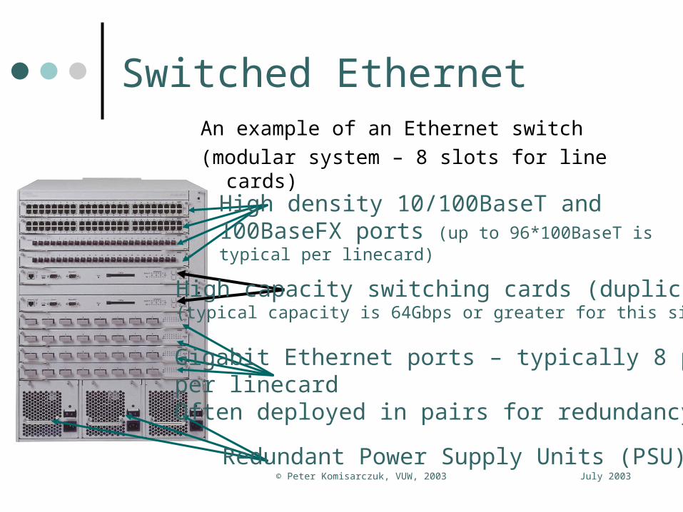
Switched EthernetAn example of an Ethernet switch
(modular system – 8 slots for line cards)
High density 10/100BaseT and 100BaseFX ports (up to 96*100BaseT is typical per linecard)
Redundant Power Supply Units (PSU)
High capacity switching cards (duplicated)(typical capacity is 64Gbps or greater for this size of box)
Gigabit Ethernet ports – typically 8 ports per linecardOften deployed in pairs for redundancy
July 2003© Peter Komisarczuk, VUW, 2003
Ethernet Trunking
If there are multiple connections between bridges the STP will turn off all but one connection to avoid circular routes within the network
If some of the connections are between the same two machines we can fool the STP into thinking multiple links are effectively a single higher capacity Ethernet connection This is good as multiple Ethernet links provide a resilient
network configuration in case fibre is cut or a port fails There are several proprietary methods and a standards
based method from the IEEE MLT (Multi-Link Trunking – Nortel Networks), PAgP
(Port Aggregation Protocol – Cisco Systems), IEEE 802.3ad LACP (Link Aggregation Control Protocol) – the standard

July 2003© Peter Komisarczuk, VUW, 2003
Ethernet Trunking Example What Cisco says:
Link Aggregation Control Protocol (LACP) is part of an IEEE specification (802.3ad) that allows you to bundle several physical ports together to form a single logical channel.
LACP allows a switch to negotiate an automatic bundle by sending LACP packets to the peer. It performs a similar function as Port Aggregation Protocol (PAgP) with Cisco EtherChannel.
• (There are two forms of EtherChannel Fast EtherChannel for bundling up 100Mbps ports and Gigabit EtherChannel for bundling up Gigabit Ethernet ports)
http://www.cisco.com/en/US/tech/tk389/tk213/tk833/tech_protocol_home.html
Hash DA/SA to a portPAgP management protocolDetects any port/fibre failureand re-computes hash to use remaining ports/fibres
July 2003© Peter Komisarczuk, VUW, 2003
Questions – switch architecture
Under what circumstance might a cut through switch need to store a whole frame? Advanced question: Where in the switch is the buffering
required? What error condition may be propagated in a cut-through
switch hub? What is the traffic capacity of a switch with 24*10Mbps ports
and 2*100Mbps ports if all ports can work at full rate? Identify the “data” that is required to be managed in the
packet forwarding table of a switch. Will it be the same for both cut-through and store-and-
forward switched hubs? What is the latency introduced by a store-and-forward
switch? Contrast that to the latency of a cut-through switch?
July 2003© Peter Komisarczuk, VUW, 2003
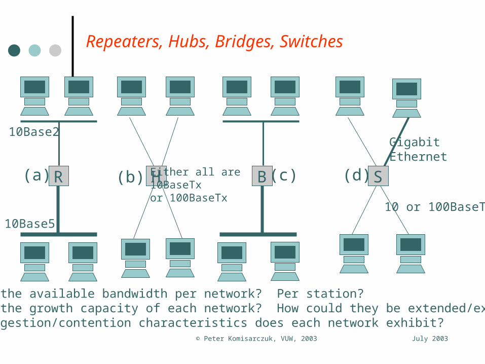
Repeaters, Hubs, Bridges, Switches
What is the available bandwidth per network? Per station?What is the growth capacity of each network? How could they be extended/expanded? What congestion/contention characteristics does each network exhibit?
R H B S
GigabitEthernet
10 or 100BaseTx
10Base5
10Base2
Either all are 10BaseTxor 100BaseTx
(a) (b) (c) (d)
July 2003© Peter Komisarczuk, VUW, 2003
Advanced Ethernet Capabilities
The following information is provided to complete a discussion of Ethernet: The IEEE developed an optional addition to the
Ethernet MAC frame• VLAN – IEEE802.1q = allows traffic to be segregated
by arbitrary allocation of stations to workgroups – as if they were on separate LANs
• Priority – IEEE802.1p = allows traffic to be prioritised at stations, bridges and switches
• E.g. time sensitive information is characterised as high priority to minimise its latency through the network
• Best effort traffic (email, file transfer, etc.) has the lowest priority
July 2003© Peter Komisarczuk, VUW, 2003
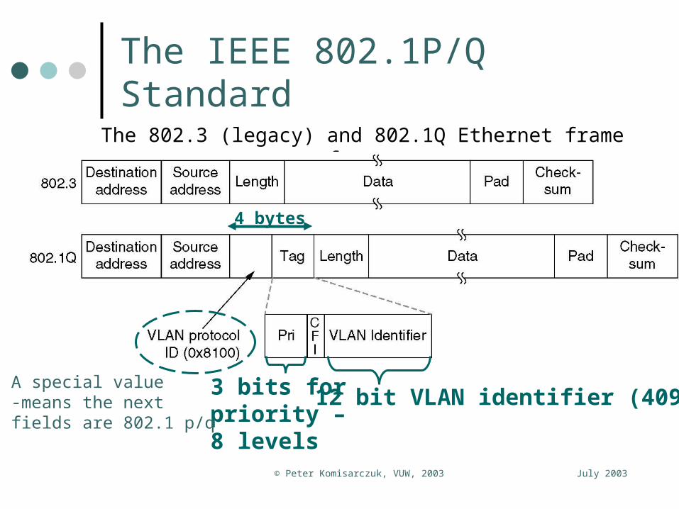
The IEEE 802.1P/Q Standard
The 802.3 (legacy) and 802.1Q Ethernet frame formats.
12 bit VLAN identifier (4095)
4 bytes
3 bits forpriority –8 levels
A special value-means the nextfields are 802.1 p/q

July 2003© Peter Komisarczuk, VUW, 2003
Virtual LANs
(a) Four physical LANs organized into two VLANs (gray and white) by two bridges.
(b) The same 15 machines organized into two VLANs by switches.

July 2003© Peter Komisarczuk, VUW, 2003
Transition to VLANs
Transition from legacy Ethernet to VLAN-aware Ethernet.
The shaded symbols (host and switch) are VLAN aware.
The white symbols (hosts) are not VLAN aware.

July 2003© Peter Komisarczuk, VUW, 2003
The 802.1P Mechanism
8 queues – one per priority type is ideal Priority 0 is reserved for network management traffic Priority 1 through 8 is user defined Priority 1 often given to voice over IP (VoIP)
Minimises the latency for voice packets as they pre-empt other packets
Priority 8 usually given to “best effort” traffic Who sets 802.1p bits?
The station can set them – latest O/S can do this based on the application/protocol (e.g. RTP)
The bridge/switch can set them – using a technique called deep packet classification

July 2003© Peter Komisarczuk, VUW, 2003
Priority Queuing – Nortel PP8600

July 2003© Peter Komisarczuk, VUW, 2003
Going Up The LAN Protocol Stack Logical Link Control User = higher layer
protocol, e.g. IP layer, mgnt Identified by SAP (Service
Access Point) at Tx and Rx – i.e. service oriented
LLC based on HDLC – flow control + error recovery
LLC is designed for Multi-access shared medium – any type of IEEE MAC
MAC layer deals with actual transmission, error detection, access to the medium etc.
LLC = IEEE802.2

July 2003© Peter Komisarczuk, VUW, 2003
LLC Service Perspective 3 LLC “service” types are defined
Unacknowledged connectionless service (type 1)• No flow or error control – errored frames are detected & dumped• Minimal logic required – used when higher layer protocols provide
error control and flow control Connection mode service (type 2)
• Extended HDLC format (address format and sequence numbers)• Logical connection is set-up between nodes, with full flow and error
control (as HDLC)• (Used in minimal systems with small connectivity requirements)
Acknowledged connectionless service (type 3)• No logical connection is set-up between stations• Each datagram is acknowledged (window size = 1)
LLC passes frames to MAC to be transmitted LLC receives non-errored frames from the MAC
July 2003© Peter Komisarczuk, VUW, 2003
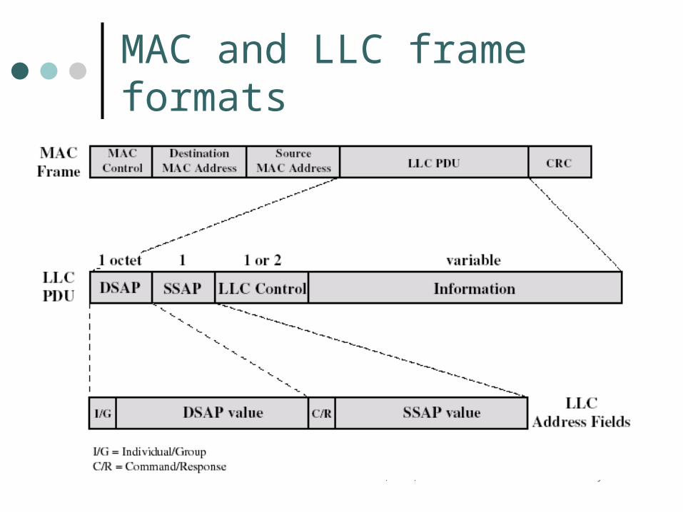
MAC and LLC frame formats

July 2003© Peter Komisarczuk, VUW, 2003
LLC frame formats DSAP and SSAP identify the network layer protocol
Just like the port number in TCP e.g. HTTP on port 80 The DSAP can be identified as a single or group
value C/R – Command/Response bit identifies frame type
LLC Control Format Based on an extended mode HDLC format with 7
bit sequence numbers:
1 2 3 4 5 6 7 8 1 2 3 4 5 6 7 80 N(S) P/F N(R)

July 2003© Peter Komisarczuk, VUW, 2003
HDLC Frames
July 2003© Peter Komisarczuk, VUW, 2003
HDLC Frames
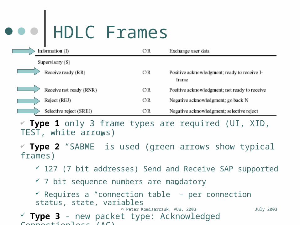
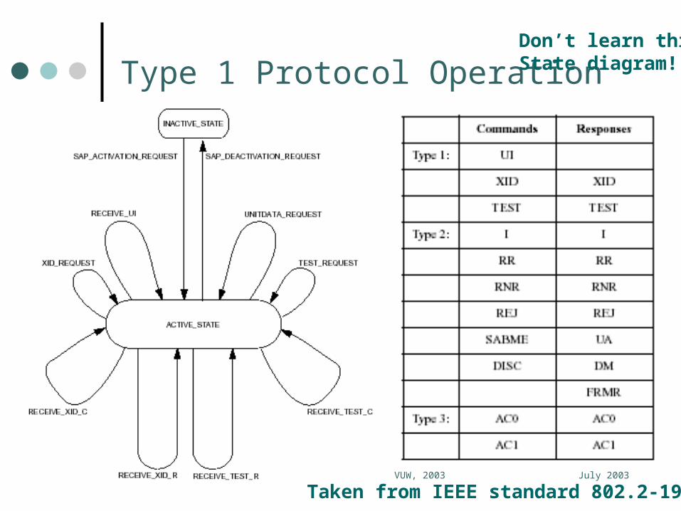
Type 1 only 3 frame types are required (UI, XID, TEST, white arrows)
Type 2 “SABME” is used (green arrows show typical frames) 127 (7 bit addresses) Send and Receive SAP supported
7 bit sequence numbers are mandatory
Requires a “connection table” – per connection status, state, variables
Type 3 - new packet type: Acknowledged Connectionless (AC) AC Information and AC response PDUs, using a 1 bit sequence number
July 2003© Peter Komisarczuk, VUW, 2003
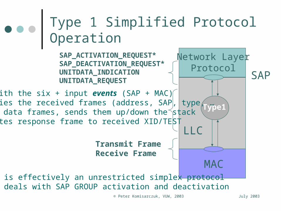
Type 1 Simplified Protocol Operation
Network LayerProtocol
Type1
SAP
MAC
LLC
SAP_ACTIVATION_REQUEST*SAP_DEACTIVATION_REQUEST*UNITDATA_INDICATIONUNITDATA_REQUEST
Transmit FrameReceive Frame
Deals with the six + input events (SAP + MAC)Classifies the received frames (address, SAP, type, …Formats data frames, sends them up/down the stackFormulates response frame to received XID/TEST
Type 1 is effectively an unrestricted simplex protocol* Also deals with SAP GROUP activation and deactivation
July 2003© Peter Komisarczuk, VUW, 2003
Type 1 Protocol Operation
Taken from IEEE standard 802.2-1998
Don’t learn thisState diagram!

July 2003© Peter Komisarczuk, VUW, 2003
Type 2 Protocol Operation (States)
Don’t learn these state transitiondiagrams Its just an example
Type 2 LLCStates and transitions as defined in the IEEE standard 802.2-1998.
Taken from IEEE standard 802.2-1998

July 2003© Peter Komisarczuk, VUW, 2003
So where does the LLC and MAC fit?
Socket App
Winsock
TCP/IP WinSock
Provider
TCP/IP Transport
Driver
NDISMiniport
NIC
UserUser
KernelKernel
NDIS = Network Driver Interface SpecificationNDIS = Network Driver Interface Specification
- allows an arbitrary interface to a number of NIC, allows an arbitrary interface to a number of NIC,
USB interfaces, etc. USB interfaces, etc.
WinSockWinSock
Traditional Microsoft ModelTraditional Microsoft Model
NICNIC
MAC and LLC (type 1) implemented in NICMAC and LLC (type 1) implemented in NIC

July 2003© Peter Komisarczuk, VUW, 2003
Questions
What “data” uniquely identifies the LLC logical connection? What is the function of the Test PDU? What is the function of the XID PDU? What is the maximum amount of data that can be
outstanding with type 3 data transfer? (e.g. in terms of the number of frames or in bytes [for Ethernet])
What is the maximum amount of data that can be outstanding with type 2 data transfer? (e.g. in terms of the number of frames or bytes [for Ethernet])
What is the amount of data outstanding with type 1 data transfer? (e.g. in frames or bytes [for Ethernet])