JOINERY SYSTEM - Lowes Holiday
12
A20465 Instruction manual 55160 77240 OMNIJIG ® JOINERY SYSTEM A24502 - 11-16-07 Rev. A Copyright © 2007 PORTER-CABLE Product may vary slightly from photo. Le produit peut être légèrement différer de la photo. El artículo puede variar levemente con relación a la foto. Product may vary slightly from picture. www.deltaportercable.com
Transcript of JOINERY SYSTEM - Lowes Holiday
A20465
Inst
ruct
ion
man
ual
55160
77240
OMNIJIG
®
JOINERY SYSTEM
A24502 -
11-1
6-0
7 R
ev.
A
Co
pyr
igh
t ©
20
07
PO
RT
ER
-CA
BL
E
Prod
uct
may
var
y sl
ight
ly f
rom
pho
to.
Le p
rodu
it p
eut
être
légè
rem
ent
diff
érer
de
la p
hoto
.
El a
rtíc
ulo
pued
e va
riar
leve
men
te c
on r
elac
ión
a la
fot
o.
Pro
duct
may
var
y sl
ight
ly
from
pic
ture
.
ww
w.d
elta
port
erca
ble.
com

PORTER-CABLE OMNIJIG® Page iii
Safe
tyGeneral safety rules
ivRouter safety
ivOMNIJIG® JOINERY SYSTEM safety
iv
Intr
oduc
tion
Joinery overview
2Standard OMNIJIG® parts
3
OMNIJIG® accessories
4
Familiarization
6Wood preparation
7Project layout
7Board lengths
8Tips for making drawers and boxes
9
Bas
ic O
pera
tions
Set
ting u
p t
he
OM
NIJ
IG®
12
Bench mounting
13
Router bit depth pod
13
Instructional DVD
13
Typic
al
omnijig
adju
stm
ents
14
Placing and sizing stops
14
Removing and replacing templates
14
Accessory templates
15
Edge guides
15
Mounting the wood
15
Variable fingers
16
Selecting bits and template guides
17
Setting router bit depth and making the cut 17
O-ring installation
17
Dov
etail s
etup g
uid
e
18
Through dovetails
Variable-spaced half-blind dovetails
Narrow pins
Single pass half-blind dovetails
Rou
ter
bit
dep
th p
od
19
User defined gauges on 24" and 16”
How to select the proper gauge
M
aki
ng c
uts
20
Safe cutting
Tip for reducing tear-out during cuts
Acc
esso
ries
20
Dust collection
20
Storage case positioning
21
Appen
dix
66-6
7
TABLE OF CONTENTS
Thro
ugh
Dov
etai
ls23 Va
riab
le-S
pace
d H
alf-B
lind
Dov
etai
ls31 Sing
le-P
ass
Hal
f-B
lind
Dov
etai
ls39
Mod
els
55160 A
ND
77240
Rab
bete
d H
alf-
Blin
d D
ovet
ails
45 Slid
ing
Tape
red
Dov
etai
ls51 Box
Joi
nts
59
Appl
icat
ions
4825 H
ighw
ay 4
5 N
orth
Ja
ckso
n, T
N 3
8305
1.8
88.8
48.5
175
del
tapor
terc
able
.com
/jig
s
A N
OTE A
BO
UT U
SIN
G T
HE O
MN
IJIG®
Though the OMNIJIG® is designed to make quality joinery from the start, we strongly suggest you practice
cutting and fitting several joints using scrap wood. This will build up your confidence in the jig and in your own
abilities. This fitting process may also require that you make adjustments to the template stops and/or router
bit depth gauges to achieve your desired joint fit for your application. At the end of each chapter there are tips
that detail these adjustments.

Page iv PORTER-CABLE OMNIJIG® Read and understand all instructions. Failure to follow all instructions listed below, may result
in electric shock, fire and/or serious personal injury.
There are certain applications for which this tool was designed. Do not modiy and/or use for
any applications other than for which it was designed. If you have any questions relative to its application DO
NOT use the tool until you have written PORTER-CABLE and we have advised you. You can write to Technical
Service Manager; PORTER-CABLE; 4825 Highway 45 North; Jackson, TN 38305.
SA
VE T
HES
E I
NS
TR
UC
TIO
NS
GEN
ER
AL S
AFETY
RU
LES
1.
KEE
P W
OR
K A
REA
CLE
AN
. Cluttered areas and benches invite injuries.
2.
AV
OID
DA
NG
ERO
US
EN
VIR
ON
MEN
T. Don’t expose power tools to rain. Don’t use power tools in damp or
wet locations. Keep area well lit. Avoid chemical or corrosive environment. Do not use tool in presence of
flammable liquids or gases.
3.
GU
AR
D A
GA
INS
T EL
ECTR
IC S
HO
CK
. Prevent body contact with grounded surfaces. For example: pipes,
radiators, ranges, refrigerator enclosures.
4.
KEE
P C
HIL
DR
EN A
WAY
. Do not let visitors contact tool or extension cord. All visitors should be kept away from
work area.
5.
STO
RE
IDLE
TO
OLS
. When not in use, tools should be stored in dry, and high or locked-up place – out of reach
of children.
6.
DO
N’T
FO
RC
E TO
OL. It will do the job better and safer at the rate for which it was intended.
7.
US
E R
IGH
T TO
OL. Don’t force small tool or attachment to do the job of a heavy duty tool. Don’t use tool for
purpose not intended – for example – do not use a circular saw for cutting tree limbs or logs.
8.
DR
ESS
PR
OP
ERLY
. Do not wear loose clothing or jewelry. Loose clothing, draw strings and jewelry can be
caught in moving parts. Rubber gloves and non-skid footwear are recommended when working outdoors.
Wear protective hair covering to contain long hair.
9.
US
E A
NS
I Z8
7.1
SA
FETY
GLA
SS
ES. Wear safety glasses or goggles while operating power tools. Also face
or dust mask if operation creates dust. All persons in the area where power tools are being operated should
also wear safety glasses and face or dust mask.
10.
WEA
R A
NS
I S
3.19
EA
R P
RO
TEC
TIO
N to safeguard against possible hearing loss.
11.
DO
N’T
AB
US
E C
OR
D. Never carry tool by cord or yank it to disconnect from receptacle. Keep cord from heat,
oil, and sharp edges. Have damaged or worn power cord and strain reliever replaced immediately. DO NOT
ATTEMPT TO REPAIR POWER CORD.
12.
SEC
UR
E W
OR
K. Use clamps or a vise to hold work. It’s safer than using your hand and it frees both hands to
operate tool.
13.
DO
N’T
OV
ERR
EAC
H. Keep proper footing and balance at all times.
14.
MA
INTA
IN T
OO
LS W
ITH
CA
RE. Keep tools sharp and clean for better and safer performance. Follow
instructions for lubricating and changing accessories. Inspect tool cords periodically and if damaged, have
repaired by authorized service facility. Inspect extension cords periodically and replace if damaged. Have all
worn, broken or lost parts replaced immediately. Keep handles dry, clean and free from oil and grease.
15.
DIS
CO
NN
ECT
TOO
LS when not in use, before servicing, and when changing accessories such as blades, bits, cutters,
etc.
16.
REM
OV
E A
DJU
STI
NG
KEY
S A
ND
WR
ENC
HES
. Form habit of checking to see that keys and adjusting
wrenches are removed from the tool before turning it on.
17.
AV
OID
UN
INTE
NTI
ON
AL
STA
RTI
NG
. Do not carry a plugged-in tool with finger on switch. Be sure switch is
off when plugging in. Keep hands, body and clothing clear of blades, bits, cutters, etc. when plugging in the
tool.
18.
STA
Y A
LER
T. Watch what you are doing. Use common sense. Do not operate tool when you are tired or while
under the influence of medication, alcohol or drugs.
19.
CH
ECK
DA
MA
GED
PA
RTS
. Before further use of the tool, a guard or other part that is damaged should
be carefully checked to determine that it will operate properly and perform its intended function. Check for
alignment of moving parts, binding of moving parts, breakage of parts, mounting, and any other conditions
that may affect its operation. A guard or other part that is damaged should be properly repaired or replaced by
an authorized service center unless otherwise indicated elsewhere in this instruction manual. Have defective
switches replaced by an authorized service center. Do not use tool if switch does not turn it on and off.
RO
UTER
SA
FETY
RU
LES
Wear appropriate hearing protection during use [ANSI S12.6 (S3.19)]. Under some conditions
and duration of use, noise from this product may contribute to hearing loss.
SAFETY RULES Some dust created by power sanding, sawing, grinding, drilling, and other construction activi-
ties contains chemicals known to cause cancer, birth defects or other reproductive harm. Some examples of
these chemicals are:
Your risk from these exposures varies, depending on how often you do this type of work. To reduce your expo-
sure to these chemicals: work in a well ventilated area, and work with approved safety equipment, such as those
dust masks that are specially designed to filter out microscopic particles.
Avoid prolonged contact with dust from power sanding, sawing, grinding, drilling, and other
construction activities. Wear protective clothing and wash exposed areas with soap and water. Allowing dust to
get into your mouth, eyes, or lay on the skin may promote absorption of harmful chemicals.
Use of this tool can generate and/or disburse dust, which may cause serious and permanent
respiratory or other injury. Always use NIOSH/OSHA approved respiratory protection appropriate for the dust
exposure. Direct particles away from face and body.
ALWAYS USE SAFETY GLASSES. Everyday eyeglasses are NOT safety glasses. Also use face
or dust mask if cutting operation is dusty. ALWAYS WEAR CERTIFIED SAFETY EQUIPMENT:
Hold tool by insulated gripping surfaces when performing an operation where the cutting tool may contact
hidden wiring or its own cord. Contact with a "live" wire will make exposed metal parts of the tool "live"
and shock the operator.
Use clamps or another practical way to secure and support the workpiece to a stable platform. Holding
the work by hand or against your body leaves it unstable and may lead to loss of control.
accumulate on interior surfaces and could create a risk of serious injury, electrical shock or death.
Never run the motor unit when it is not inserted in one of the router bases. The motor is not designed to
be handheld.
Keep handles dry, clean, and free from oil and grease. This will enable better control of the tool.
Keep hands away from cutting area. Never reach under the workpiece for any reason. Keep the router base
firmly in contact with the workpiece when cutting. Hold the router only by the handles. These precautions
will reduce the risk of personal injury.
Use sharp cutters. Dull cutters may cause the router to swerve or stall under pressure.
Never touch the bit immediately after use. It may be extremely hot.
Be sure that the motor has stopped completely before you lay the router down. If the cutter head is still
spinning when the tool is laid down, it could cause injury or damage.
Be sure that the router bit is clear of the workpiece before starting the motor. If the bit is in contact with
the workpiece when the motor starts it could make the router jump, causing damage or injury.
Do not press spindle lock button while the motor is running. Doing so can damage the spindle lock.
OM
NIJ
IG®
JO
INER
Y S
YS
TEM
SA
FETY
RU
LES
To reduce the risk of injury, when making cuts: OMNIJIG® JOINERY SYSTEM and
making your desired joint.
OMNIJIG® have been tightened following any
adjustments.
stops spinning.
wood on and off the jig.
cause sparks.
PORTER-CABLE OMNIJIG® Page 1INTRODUCTION
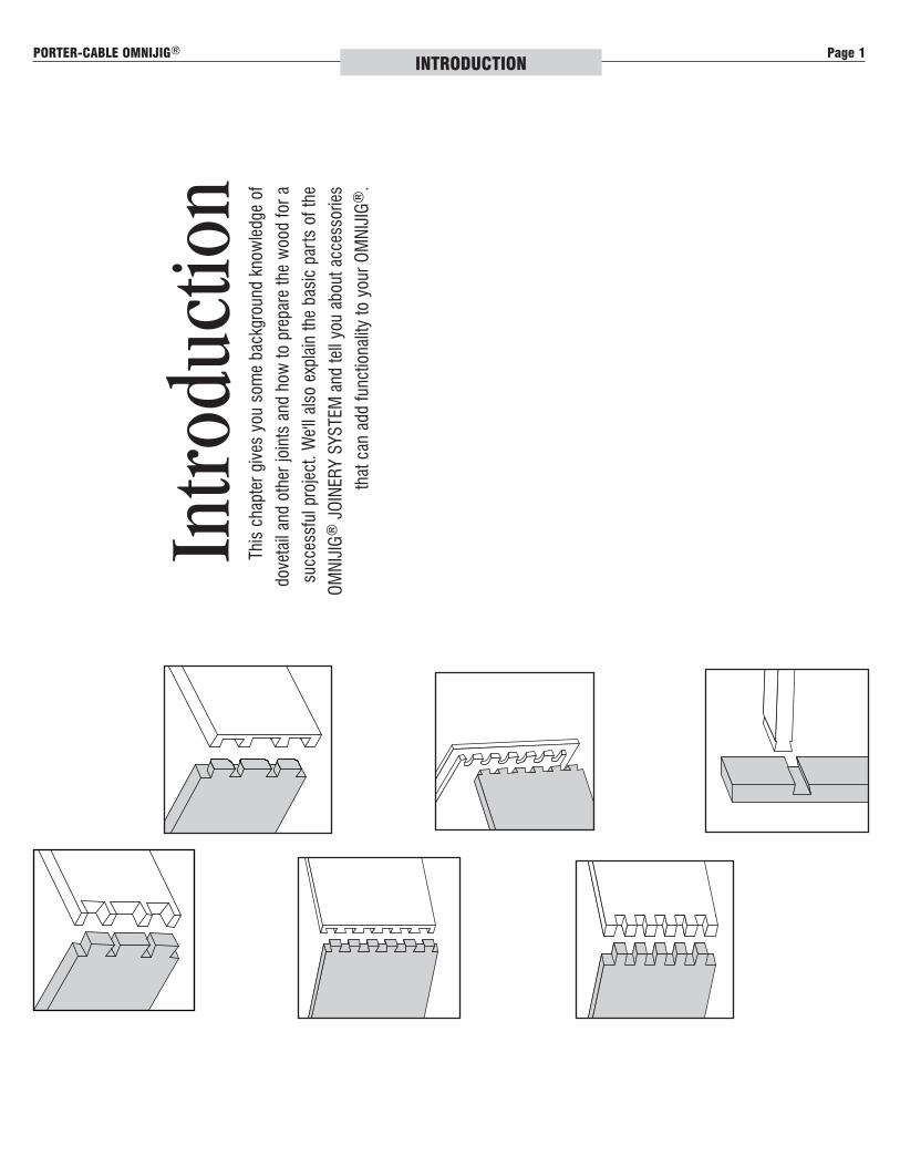
This chapter gives you some background knowledge of
dovetail and other joints and how to prepare the wood for a
successful project. We'll also explain the basic parts of the
OMNIJIG® JOINERY SYSTEM and tell you about accessories
that can add functionality to your OMNIJIG®.
Intr
oduc
tion
Page 2 PORTER-CABLE OMNIJIG®INTRODUCTION
JOIN
ER
Y O
VER
VIE
W
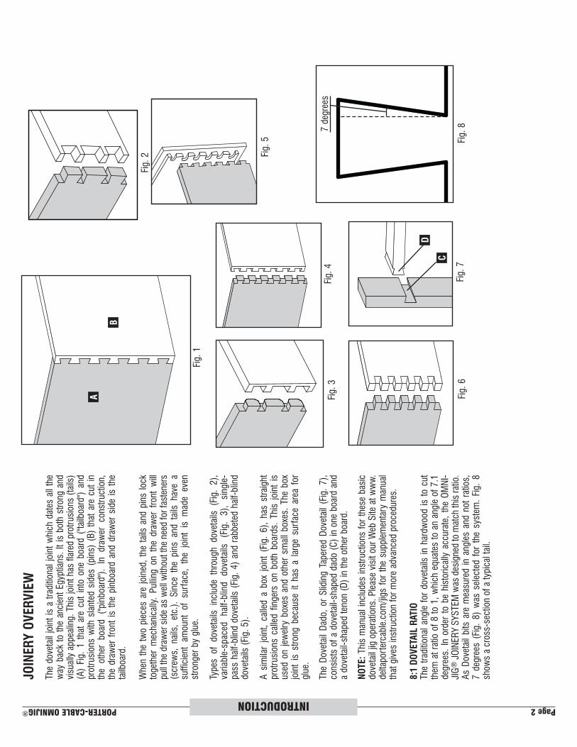
The dovetail joint is a traditional joint which dates all the
way back to the ancient Egyptians. It is both strong and
visually appealing. This joint has flared protrusions (tails)
(A) Fig. 1 that are cut into one board ("tailboard") and
protrusions with slanted sides (pins) (B) that are cut in
the other board ("pinboard"). In drawer construction,
the drawer front is the pinboard and drawer side is the
tailboard.
When the two pieces are joined, the tails and pins lock
together mechanically. Pulling on the drawer front will
pull the drawer side as well without the need for fasteners
(screws, nails, etc.). Since the pins and tails have a
sufficient amount of surface, the joint is made even
stronger by glue.
Types of dovetails include through dovetails (Fig. 2),
variable-spaced half-blind dovetails (Fig. 3), single-
pass half-blind dovetails (Fig. 4) and rabbeted half-blind
dovetails (Fig. 5).
A similar joint, called a box joint (Fig. 6), has straight
protrusions called fingers on both boards. This joint is
used on jewelry boxes and other small boxes. The box
joint is strong because it has a large surface area for
glue.
The Dovetail Dado, or Sliding Tapered Dovetail (Fig. 7),
consists of a dovetail-shaped dado (C) in one board and
a dovetail-shaped tenon (D) in the other board.
NO
TE: This manual includes instructions for these basic
dovetail jig operations. Please visit our Web Site at www.
deltaportercable.com/jigs for the supplementary manual
that gives instruction for more advanced procedures.
8:1
DO
VETA
IL R
ATIO
The traditional angle for dovetails in hardwood is to cut
them at ratio of 8 to 1, which equates to an angle of 7.1
degrees. In order to be historically accurate, the OMNI-
JIG® JOINERY SYSTEM was designed to match this ratio.
As Dovetail bits are measured in angles and not ratios,
7 degrees (Fig. 8) was selected for the system. Fig. 8
shows a cross-section of a typical tail.
Fig. 1
Fig. 2
Fig. 3
Fig. 4
Fig. 5
Fig. 6
B
A
Fig. 7
C
D
Fig. 87 degrees

PORTER-CABLE OMNIJIG® Page 3INTRODUCTION
STA
ND
AR
D O
MIN
JIG®
PA
RTS
The OMNIJIG® comes standard with various
bits, template guides, stops and a template.
The
24"
OM
NIJ
IG® comes standard with a
variable finger template that is used to cut through
dovetails and half-blind dovetails (variable and
s ingle-pass).
The
16"
OM
NIJ
IG® comes standard with a
single-pass half-blind/sliding tapered dovetail
template that is used to cut single-pass half-blind
joints and the sliding tapered dovetail dado.
Standard equipment for each is shown here.
77240:
24"
OM
NIJ
IG S
YS
TEM
1. Jig base
2. 24" variable finger template
3. Instructional DVD
4. Left and right stops (labeled A4, B1, C1)
5. Dovetail bit (labeled D4)
6. Straight bit (labeled S2)
7. Square screwdriver
8. Wrench
9. Template guides, G0 (85/128"), G1 (5/8"),
G2 (39/64"), G3 (19/32"), G4 (37/64"), G5
(9/16") and G6 (15/32")
10. Lock nuts (for all template guides)
11. Router bit depth pod
12. Stabilizer bar
13. Two rubber O-rings
14. Dovetail setup guide (not shown)
55160:
16"
OM
NIJ
IG S
YS
TEM
1. Jig base
2. 16" single-pass half-blind/sliding tapered
dovetail template
3. Instructional DVD
4. Left and right stops (labeled C2)
5. Dovetail bit (labeled D4)
6. Square screwdriver
7. Wrench
8. Template guides, labeled G2 (39/64"), G3
(19/32"), G4 (37/64") and G5 (9/16")
9. Lock nut (for all template guides)
10. Stabilizer bar
11. Router bit depth pod
12. Two rubber O-rings
55160
77240
1 2
3
44
56
7
8 9
4
1 2
3
4
56
87
9 10
11
12
10
11
13
12
Page 4 PORTER-CABLE OMNIJIG®INTRODUCTION
OM
NIJ
IG® A
CC
ES
SO
RIE
S
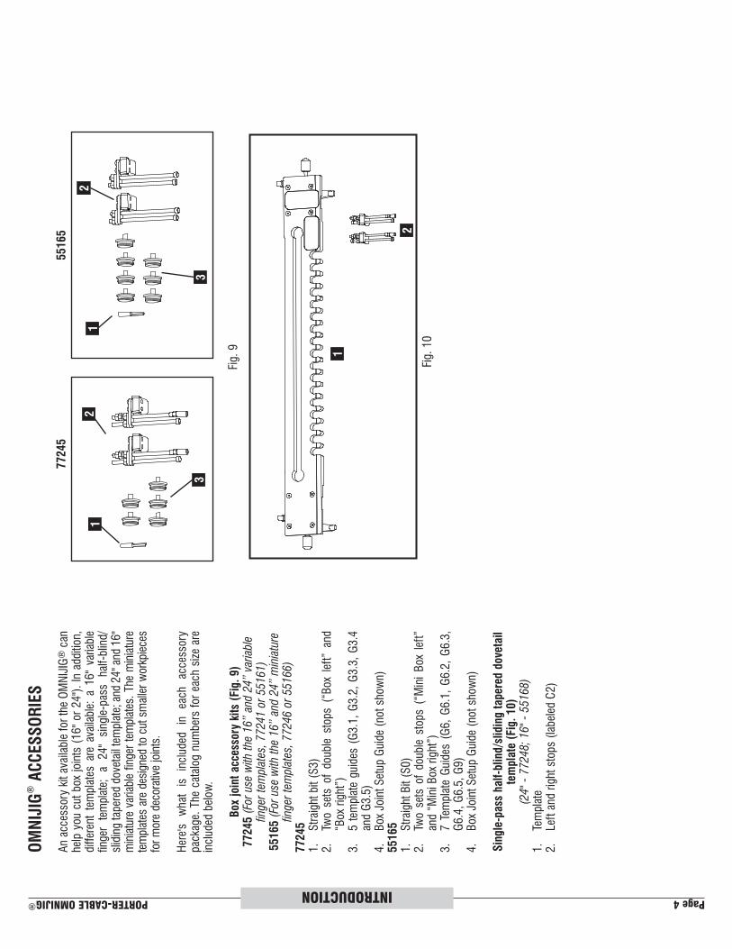
An accessory kit available for the OMNIJIG® can
help you cut box joints (16" or 24"). In addition,
different templates are available: a 16" variable
finger template; a 24" single-pass half-blind/
sliding tapered dovetail template; and 24" and 16"
miniature variable finger templates. The miniature
templates are designed to cut smaller workpieces
for more decorative joints.
Here's what is included in each accessory
package. The catalog numbers for each size are
included below.
Box
joi
nt
acc
esso
ry k
its
(Fig
. 9)
77245 (
For
use
with
the
16”
and 2
4”
vari
able
fin
ger
tem
pla
tes,
77241 o
r 55161)
55165
(Fo
r us
e w
ith t
he 1
6”
and 2
4”
min
iatu
re
finger
tem
pla
tes,
77246 o
r 55166)
77245
1. Straight bit (S3)
2. Two sets of double stops (“Box left” and
“Box right”)
3. 5 template guides (G3.1, G3.2, G3.3, G3.4
and G3.5)
4. Box Joint Setup Guide (not shown)
55165
1. Straight Bit (S0)
2. Two sets of double stops (“Mini Box left”
and “Mini Box right”)
3. 7 Template Guides (G6, G6.1, G6.2, G6.3,
G6.4, G6.5, G9)
4. Box Joint Setup Guide (not shown)
Sin
gle
-pass
half
-blind/s
lidin
g t
aper
ed d
ovet
ail
tem
pla
te (
Fig
. 10)
(24"
- 77248;
16"
- 55168)
1. Template
2. Left and right stops (labeled C2)
Fig. 9
Fig. 10
12
3
2
1
12
3
77245
55165

PORTER-CABLE OMNIJIG® Page 5INTRODUCTION
Fig. 11
Fig. 12
Vari
able
fin
ger
tem
pla
te (
Fig
. 11)
(24"
- 77241;
16"
- 55161)
1. Template
2. Router bit depth gauges
3. Left and right stops (labeled A4, B1 and C1)
(FO
R 5
5161 O
NLY
:)4. Template guides, one labeled G1 (5/8"), one labeled G6
(15/32") and one labeled G0 (85/128")
5. Lock nut for template guides
6. Straight bit (labeled S2)
7. One rubber O-ring
8. Dovetail setup guide (not shown)
Min
iatu
re v
ari
able
fin
ger
tem
pla
te (
Fig
. 12)
(24"
- 77246;
16"
- 55166)
1. Template
2. Dovetail bit (labeled D1)
3. Straight bit (labeled S1)
4. Template guides, one labeled G7 (3/8") and one labeled
G8 (23/64")
5. Lock nut for template guides
6. Left and right stops (labeled A8 and B2)
7. Router bit depth gauge
8. One rubber O-ring
9. Dovetail setup guide (not shown)
SP
EC
IFIC
ATIO
NS
OF R
OU
TER
BIT
S I
NC
LUD
ED
IN
VA
RIO
US
BA
SE U
NIT
S A
ND
AC
CES
SO
RIE
S:
Router
Bits
Cutting
Diameter
Flute
Length
Shank
Length
D0
1/4"
13/32"
1/4"
D1
9/32"
17/32"
1/4"
D2
5/16"
21/32"
1/4"
D3
3/8"
25/32"
1/2"
D4
1/2"
25/32"
1/2"
D5
9/16"
1-1/32"
1/2"
D6
3/4"
1-17/32"
1/2"
S0
9/32"
25/32"
1/4"
S1
1/4"
21/32"
1/4"
S2
3/8"
1-17/32"
1/2"
S3
31/64"
1-17/32"
1/2"
1
24
56
1
23
5
6
7
4
7
8
3
NO
TE: Other router bits and other accessories (dust collection adapter, storage box for tools, etc.) are
available to expand the capabilities of your OMNIJIG®. Contact your nearest PORTER-CABLE dealer for
more information.
Page 6 PORTER-CABLE OMNIJIG®INTRODUCTION
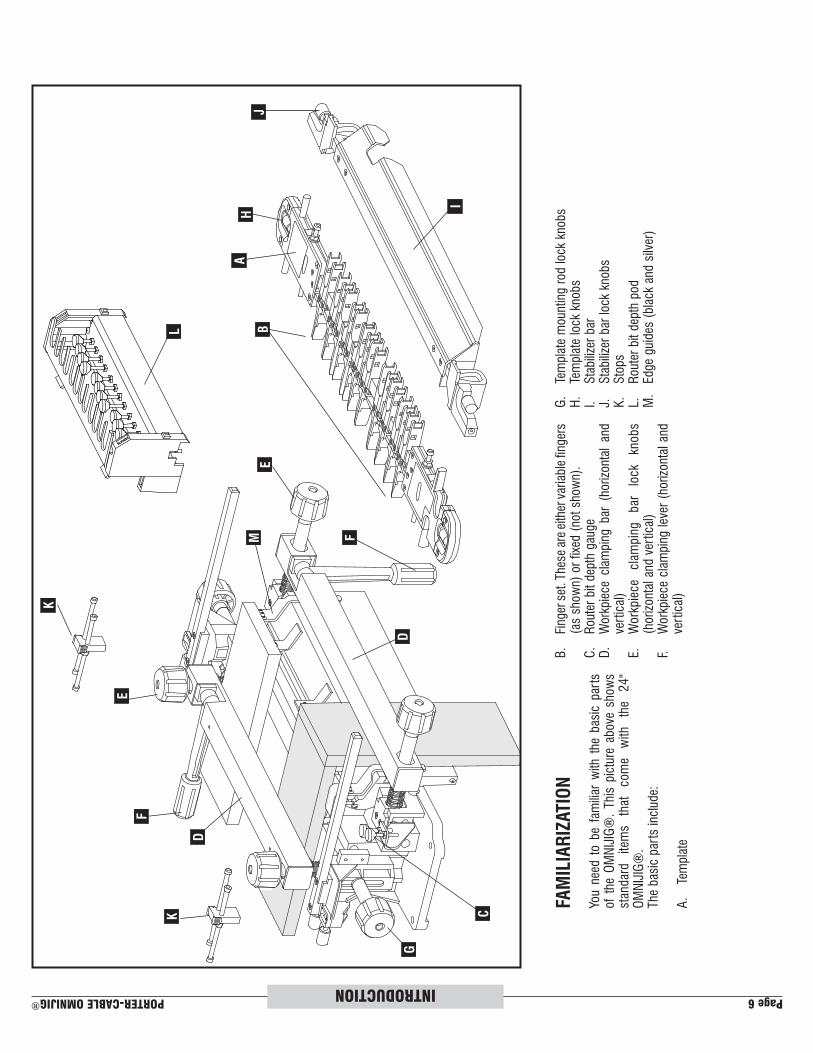
FAM
ILIA
RIZ
ATIO
N
You need to be familiar with the basic parts
of the OMNIJIG®. This picture above shows
standard items that come with the 24"
OMNIJIG®.
The basic parts include:
A. Template
B. Finger set. These are either variable fingers
(as shown) or fixed (not shown).
C. Router bit depth gauge
D. Workpiece clamping bar (horizontal and
vertical)
E. Workpiece clamping bar lock knobs
(horizontal and vertical)
F. Workpiece clamping lever (horizontal and
vertical)
G. Template mounting rod lock knobs
H. Template lock knobs
I. Stabilizer bar
J. Stabilizer bar lock knobs
K. Stops
L. Router bit depth pod
M. Edge guides (black and silver)
A
D
C
D
B
E
F
G
H
I
J
K
L
M
K
E
F

PORTER-CABLE OMNIJIG® Page 7INTRODUCTION
WO
OD
PR
EPA
RATIO
NProperly preparing the materials for your project is the key to
good-looking and tight-fitting joints. You must cut your wood
at perfect right angles (Fig. 13). Cuts that are off even one
degree will not align correctly (Fig. 14).
Also, your workpieces must be flat and not cupped. Orient
your wood so that end grain is joined to end grain (Fig. 15)
to make the joint strong. Using the long grain (Fig. 16) in the
workpiece will result in a weak joint.
INSPECT MATERIALS FOR DEFECTS. Knots
and splinters can be thrown with great force. Make sure
defective materials are not used on the OMNIJIG®.
PR
OJE
CT L
AY
OU
TKeeping track of the outer and inner face of each workpiece
and how the different parts mate with each other is very
important.
STEP 1: Lay out the workpieces face down and label the
inside faces with an “I" (Fig. 17). Label the other
side "O" for "outside surface."
STEP 2: Label the corners “A", “B", “C", and “D" (Fig. 18).
STEP 3: Label the tail boards (drawer sides) with a “T"
(Fig. 19).
STEP 4: Label the pin boards (drawer front and back) with
a “P" (Fig. 20)
Fig. 13
Fig. 14
Fig. 15
Fig. 16
Fig. 17
Fig. 19
Fig. 18
Fig. 20
I
II
I
BB
D
DA
A
CC
TT
P
P
long grain
Page 8 PORTER-CABLE OMNIJIG®INTRODUCTION
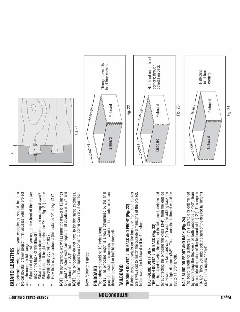
BO
AR
D L
EN
GTH
STo determine what length your workpieces should be in a
typical dovetail drawer project, first visualize your final project
and determine the following:
* What kind of joints will you use on the front of the drawer
and on the back of the drawer?
* What are the outside dimensions of the resulting drawer?
* What is the tail height (the distance "Y" in Fig. 21) on the
dovetail joints you will make?
* How thick is your pinboard (the distance "X" in Fig. 21)?
NO
TE: For our example, we will assume the drawer is 12 inches
long and 10 inches wide; tail height for all dovetails is 3/8"; and
the pinboards are 3/4" thick
NO
TE: The pinboards do not have to be the same thickness.
Also, the tail height from corner to corner can vary if desired.
Now, follow this guide:
PIN
BO
AR
DThe pinboard should be 10 inches long.
NO
TE: The pinboard length is always determined by the final
project outside dimensions - whether the joints used are
through dovetail or half-blind dovetail.
TAIL
BO
AR
D
TH
RO
UG
H D
OV
ETA
IL O
N B
AC
K A
ND
FR
ON
T (
Fig
. 22)
If doing through dovetails on the back and front, both boards
are always cut to match the outside dimensions of the project.
In this case, the tailboard will be 12 inches.
HA
LF-B
LIN
D O
N F
RO
NT/
TH
RO
UG
H D
OV
ETA
IL O
N B
AC
K (
Fig
. 23)
For a half-blind dovetail, the length of the tailboard is determined
by subtracting the pinboard thickness (3/4") from the outside
dimension of the tailboard side (12") and then adding back the
tail height distance (3/8"). This means the tailboard would be
cut to 11 5/8" length.
HA
LF-B
LIN
D O
N F
RO
NT A
ND
BA
CK
(Fig
. 24)
The board length for tailboards in this example is determined
by subtracting the thickness of both pinboards (1-1/2") from
the outside dimension of the tailboard side (12"). This equals
10-1/2". Then, you add back the sum of the desired tail heights
(3/4"). This equals 11-1/4".
Through dovetails
in all four corners
Half-blind on the front
corners; through
dovetail on back
Half-blind
in all four
corners
X
Y
Fig. 21
Pinboard
Tailboard
Pinboard
Tailboard
Fig. 22
Fig. 23
Fig. 24
10 INCHES
12 INCHES
10 INCHES
12 INCHES
10 INCHES
12 INCHES
Pinboard
Tailboard

PORTER-CABLE OMNIJIG® Page 9INTRODUCTION
Fig. 25
Fig. 26
Fig. 27
Fig. 28
VISIBLE
HIDDEN
VISIBLE
A
BGROOVE IN HALF-BLIND DOVETAIL
PINBOARD ALIGNED WITH TAIL
TIP
S F
OR
MA
KIN
G
DR
AW
ER
S A
ND
BO
XES
Tails (A) Fig. 25 are cut into the sides of the drawers, while
pins (B) are cut into the fronts and backs of drawers.
You can use either solid wood or plywood for the drawer
bottoms. Insert the bottoms in a groove along the bottom of
the inside fronts and sides. Allow the drawer bottom to be
free-floating (without glue) to allow for seasonal expansion
and contraction.
The grooves can go all the way to the ends of the boards
if the joints are half-blind dovetails. To accomplish this,
position the groove so that it runs through one of the tails on
the side (Fig. 26).
You will have to stop the grooves on through dovetails or box
joints before they reach the end of the board to prevent them
from being seen, as shown in Fig. 27.
Fig. 28 shows what the groove looks like in the board when it
is hidden or visible in the through dovetail or box joints.