
JL-Spring-2012-9 (1)
16
Spring 2012 | PCI Journal 48 P recast, prestressed concrete side-by-side box beams are widely used in short- and medium-span highway bridges because of their simple design, low life- cycle costs, quick and easy construction, and low depth-to- span ratio. Side-by-side box-beam bridges are strong, du- rable, and attractive. 1 The superstructure is constructed by placing precast, prestressed concrete box beams adjacent to each other with gaps between beams of a width ranging from 1.5 in. to 3.0 in. (38 mm to 76 mm); grouting full- depth shear keys between the box beams with a nonshrink grout, applying transverse post-tensioning (TPT) through transverse diaphragms, and casting a 3-in.- to 6-in.-thick (75 mm to 150 mm) reinforced concrete deck slab. Suc- cessful integration of the box beams, shear keys, TPT, and deck slab enables the bridge to behave monolithically. The development of longitudinal cracks in the deck slab between the box beams is a major concern and is frequent- ly reported by inspectors. 1,2 The longitudinal cracks allow water and deicing chemicals to penetrate into the sides of the box beams and cause corrosion of the steel reinforce- ment with associated concrete spalling. Over time, this deterioration requires costly repairs ranging from patching to deck and beam replacement. Different mechanisms have been proposed as the primary cause of longitudinal deck cracking. Some researchers attribute it to long-term neglect of preventive maintenance, improper handling during construction, and inadequate ■ Side-by-side box-beam bridges can exhibit longitudinal deck cracking over the shear keys as early as a few years after initial construction. ■ This paper reports on experimental investigations, numerical modeling, and field observations regarding transverse post- tensioning to mitigate this cracking. ■ Transverse post-tensioning can be determined as a function of bridge geometry such that deck cracking due to temperature changes and traffic loads is mitigated. ■ The recommended transverse post-tensioning system is defined by the number of diaphragms and the force applied at each diaphragm. Transverse post-tensioning arrangement for side-by-side box-beam bridges Nabil F. Grace, Elin A. Jensen, and Mena R. Bebawy
description
CFCC CFRP rods, tendonsstructural engineeringPCI JOURNAL
Transcript of JL-Spring-2012-9 (1)
Spr ing 2012 | PCI Journal48
Precast, prestressed concrete side-by-side box beams are widely used in short- and medium-span highway bridges because of their simple design, low life-
cycle costs, quick and easy construction, and low depth-to-span ratio. Side-by-side box-beam bridges are strong, du-rable, and attractive.1 The superstructure is constructed by placing precast, prestressed concrete box beams adjacent to each other with gaps between beams of a width ranging from 1.5 in. to 3.0 in. (38 mm to 76 mm); grouting full-depth shear keys between the box beams with a nonshrink grout, applying transverse post-tensioning (TPT) through transverse diaphragms, and casting a 3-in.- to 6-in.-thick (75 mm to 150 mm) reinforced concrete deck slab. Suc-cessful integration of the box beams, shear keys, TPT, and deck slab enables the bridge to behave monolithically.
The development of longitudinal cracks in the deck slab between the box beams is a major concern and is frequent-ly reported by inspectors.1,2 The longitudinal cracks allow water and deicing chemicals to penetrate into the sides of the box beams and cause corrosion of the steel reinforce-ment with associated concrete spalling. Over time, this deterioration requires costly repairs ranging from patching to deck and beam replacement.
Different mechanisms have been proposed as the primary cause of longitudinal deck cracking. Some researchers attribute it to long-term neglect of preventive maintenance, improper handling during construction, and inadequate
■ Side-by-side box-beam bridges can exhibit longitudinal deck cracking over the shear keys as early as a few years after initial construction.
■ This paper reports on experimental investigations, numerical modeling, and field observations regarding transverse post-tensioning to mitigate this cracking.
■ Transverse post-tensioning can be determined as a function of bridge geometry such that deck cracking due to temperature changes and traffic loads is mitigated.
■ The recommended transverse post-tensioning system is defined by the number of diaphragms and the force applied at each diaphragm.
Transverse post-tensioning arrangement for side-by-side box-beam bridges
Nabil F. Grace, Elin A. Jensen, and Mena R. Bebawy
49PCI Journal | Spr ing 2012
shear-key performance.3 Others attribute it to excessive relative vertical displacement between adjacent box beams, which leads to the failure of the shear key as well.4
To mitigate longitudinal deck cracking, different methods have been developed to analyze and design the connec-tion between the box beams. For example, Bakht et al.5 assumed that the load transfer from one beam to another was primarily through transverse shear, while transverse flexural rigidity was neglected. El-Remaily et al.6 based their calculation for the required TPT force on the flexural rigidity and the lateral moment induced in the bridge due to moving traffic. Many agencies, such as the Michigan Department of Transportation (MDOT), use field experi-ence to establish the number of diaphragms for each bridge span.7 According to MDOT Bridge Design Guides,7 four, five, six, or seven diaphragms are used for bridges with spans up to 50 ft (15 m), from 50 ft to 62 ft (19 m), from 62 ft to 100 ft (30.5 m), or over 100 ft, respectively. The level of TPT force per diaphragm is determined based on the design truck load. For example, a TPT force of 82.5 kip or 104.5 kip (367 kN or 464.8 kN) is required if the design truck is HS-20 or HS-25, respectively.
The methods used for analyzing the shear-key joint are based on the assumption that traffic loads are the key load action causing the initiation and propagation of longitu-dinal cracks in side-by-side box-beam bridges. However, some experimental investigations indicate that stresses as-sociated with thermal gradients are the main cause of crack initiation, while crack propagation is controlled by traffic loads.8,9
Research significance
Longitudinal deck cracking continues to be the primary cause of premature deterioration in side-by-side box-beam bridges. This comprehensive study combines the load ac-tions from temperature gradient and traffic in determining the required TPT arrangement to mitigate crack initiation in the bridge deck. The findings are presented in design charts to enable design engineers to establish the adequate number of diaphragms and the proper TPT force per dia-phragm based on the bridge span and width, respectively.
Objectives and scope
The goal of this study is to demonstrate that longitudinal deck cracking can be mitigated in side-by-side box-beam bridges by optimizing the TPT arrangement. The optimized TPT arrangement is established by analyzing and design-ing the bridge superstructure considering the combined ac-tions from both traffic and temperature gradient. To achieve this goal, the following was done:
• Information and observations from the field were gath-ered and analyzed.
• A half-scale, experimental box-beam bridge model was constructed. The experimental bridge model was subjected to various loading arrangements to deter-mine the influence of the traffic loads on the initiation of longitudinal deck cracking.
• A numerical study was generated and validated, using the data collected from the field and from the ex-perimental bridge model, to study in detail the stress distribution and the development of the cracks in box-beam bridges due to temperature gradient and traffic loads.
• The numerical study was extended to simulate box-beam bridges with various spans and widths. The numerical bridge models were generated and analyzed to determine the number of diaphragms and TPT force required to mitigate longitudinal deck cracking due to the combined effect of temperature gradient and traffic loads.
Field observations
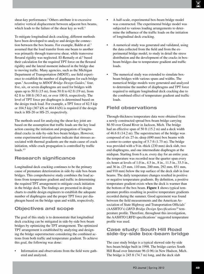
Through-thickness temperature data were obtained from a newly constructed spread box-beam bridge carrying M-50 over Grand River in Jackson, Mich. The bridge had an effective span of 50 ft (15.2 m) and a deck width of 46.6 ft (14.2 m). The superstructure of the bridge was composed of six 27-in.-deep (690 mm) box beams with a center-to-center spacing of 5.7 ft (1.75 m). The bridge was provided with a 9-in.-thick (230 mm) deck slab, two end diaphragms, and one intermediate diaphragm at the midspan. Starting from 6 a.m. every day for an entire year, the temperature was recorded near the quarter span every six hours at levels of 1.0 in., 4.5 in., 8 in., 11.5 in., 33.5 in., and 36 in. (25 mm, 110 mm, 200 mm, 292 mm, 851 mm, and 910 mm) below the top surface of the deck slab in four beams. The daily temperature changes resulted in positive or negative temperature gradients. By definition, a positive temperature gradient exists when the deck is warmer than the bottom of the box beam. Figure 1 shows typical tem-perature profiles resulting in positive temperature gradients recorded during the summer. Good agreement was found between the field measurements and the American As-sociation of State Highway and Transportation Officials’ (AASHTO’s) LRFD Bridge Design Specifications10 tem-perature profile. Therefore, throughout this investigation, the AASHTO LRFD specifications’ suggested temperature profile was used.
Case study: South Hill Road side-by-side box-beam bridge
The case study bridge is a typical skewed side-by-side box-beam bridge built in 1998. The bridge carries South Hill Road over Interstate 96 (I-96) in New Hudson, Mich. The bridge is 245 ft (74.7 m) long, and the deck slab
Spr ing 2012 | PCI Journal50
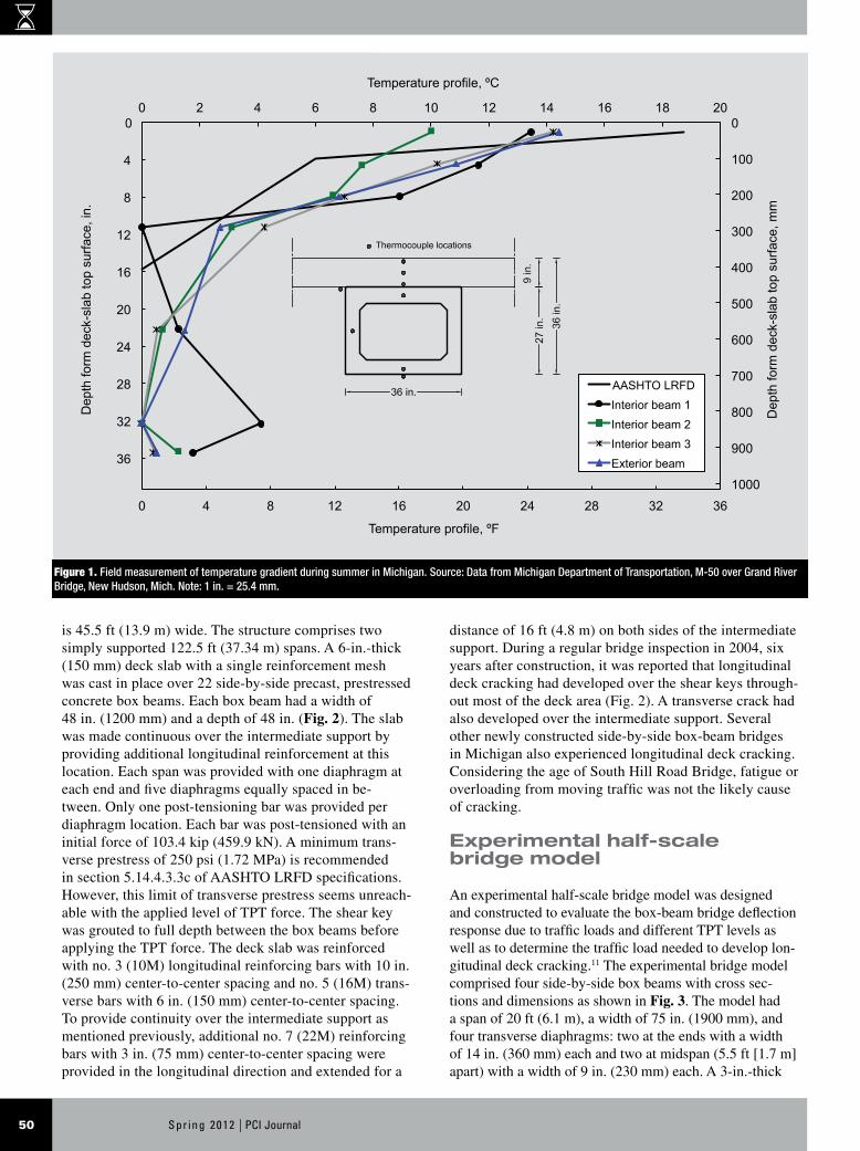
is 45.5 ft (13.9 m) wide. The structure comprises two simply supported 122.5 ft (37.34 m) spans. A 6-in.-thick (150 mm) deck slab with a single reinforcement mesh was cast in place over 22 side-by-side precast, prestressed concrete box beams. Each box beam had a width of 48 in. (1200 mm) and a depth of 48 in. (Fig. 2). The slab was made continuous over the intermediate support by providing additional longitudinal reinforcement at this location. Each span was provided with one diaphragm at each end and five diaphragms equally spaced in be-tween. Only one post-tensioning bar was provided per diaphragm location. Each bar was post-tensioned with an initial force of 103.4 kip (459.9 kN). A minimum trans-verse prestress of 250 psi (1.72 MPa) is recommended in section 5.14.4.3.3c of AASHTO LRFD specifications. However, this limit of transverse prestress seems unreach-able with the applied level of TPT force. The shear key was grouted to full depth between the box beams before applying the TPT force. The deck slab was reinforced with no. 3 (10M) longitudinal reinforcing bars with 10 in. (250 mm) center-to-center spacing and no. 5 (16M) trans-verse bars with 6 in. (150 mm) center-to-center spacing. To provide continuity over the intermediate support as mentioned previously, additional no. 7 (22M) reinforcing bars with 3 in. (75 mm) center-to-center spacing were provided in the longitudinal direction and extended for a
distance of 16 ft (4.8 m) on both sides of the intermediate support. During a regular bridge inspection in 2004, six years after construction, it was reported that longitudinal deck cracking had developed over the shear keys through-out most of the deck area (Fig. 2). A transverse crack had also developed over the intermediate support. Several other newly constructed side-by-side box-beam bridges in Michigan also experienced longitudinal deck cracking. Considering the age of South Hill Road Bridge, fatigue or overloading from moving traffic was not the likely cause of cracking.
Experimental half-scale bridge model
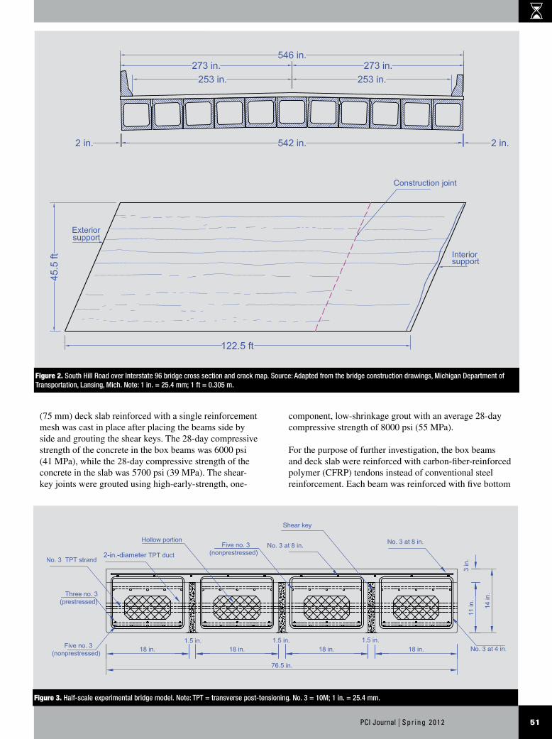
An experimental half-scale bridge model was designed and constructed to evaluate the box-beam bridge deflection response due to traffic loads and different TPT levels as well as to determine the traffic load needed to develop lon-gitudinal deck cracking.11 The experimental bridge model comprised four side-by-side box beams with cross sec-tions and dimensions as shown in Fig. 3. The model had a span of 20 ft (6.1 m), a width of 75 in. (1900 mm), and four transverse diaphragms: two at the ends with a width of 14 in. (360 mm) each and two at midspan (5.5 ft [1.7 m] apart) with a width of 9 in. (230 mm) each. A 3-in.-thick
Figure 1. Field measurement of temperature gradient during summer in Michigan. Source: Data from Michigan Department of Transportation, M-50 over Grand River Bridge, New Hudson, Mich. Note: 1 in. = 25.4 mm.
0 0
100
200
300
400
500
600
700
800
900
1000
0 2 4 6 8 8 10 12 14 16 18 20 0
4
8
12
16
20
24
28
32
36
0 4 8 12 16 20 24 28 32 36
Dep
th fo
rm d
eck-
slab
top
surfa
ce, m
m
Temperature profile, ºC D
epth
form
dec
k-sl
ab to
p su
rface
, in.
Temperature profile, ºF
AASHTO LRFD Interior beam 1 Interior beam 2 Interior beam 3 Exterior beam
51PCI Journal | Spr ing 2012
component, low-shrinkage grout with an average 28-day compressive strength of 8000 psi (55 MPa).
For the purpose of further investigation, the box beams and deck slab were reinforced with carbon-fiber-reinforced polymer (CFRP) tendons instead of conventional steel reinforcement. Each beam was reinforced with five bottom
(75 mm) deck slab reinforced with a single reinforcement mesh was cast in place after placing the beams side by side and grouting the shear keys. The 28-day compressive strength of the concrete in the box beams was 6000 psi (41 MPa), while the 28-day compressive strength of the concrete in the slab was 5700 psi (39 MPa). The shear-key joints were grouted using high-early-strength, one-
Figure 2. South Hill Road over Interstate 96 bridge cross section and crack map. Source: Adapted from the bridge construction drawings, Michigan Department of Transportation, Lansing, Mich. Note: 1 in. = 25.4 mm; 1 ft = 0.305 m.
Figure 3. Half-scale experimental bridge model. Note: TPT = transverse post-tensioning. No. 3 = 10M; 1 in. = 25.4 mm.
Spr ing 2012 | PCI Journal52
and 0 kip (90 kN, 45 kN, and 0 kN). Applying the service load did not yield any longitudinal deck cracking in these load cases.
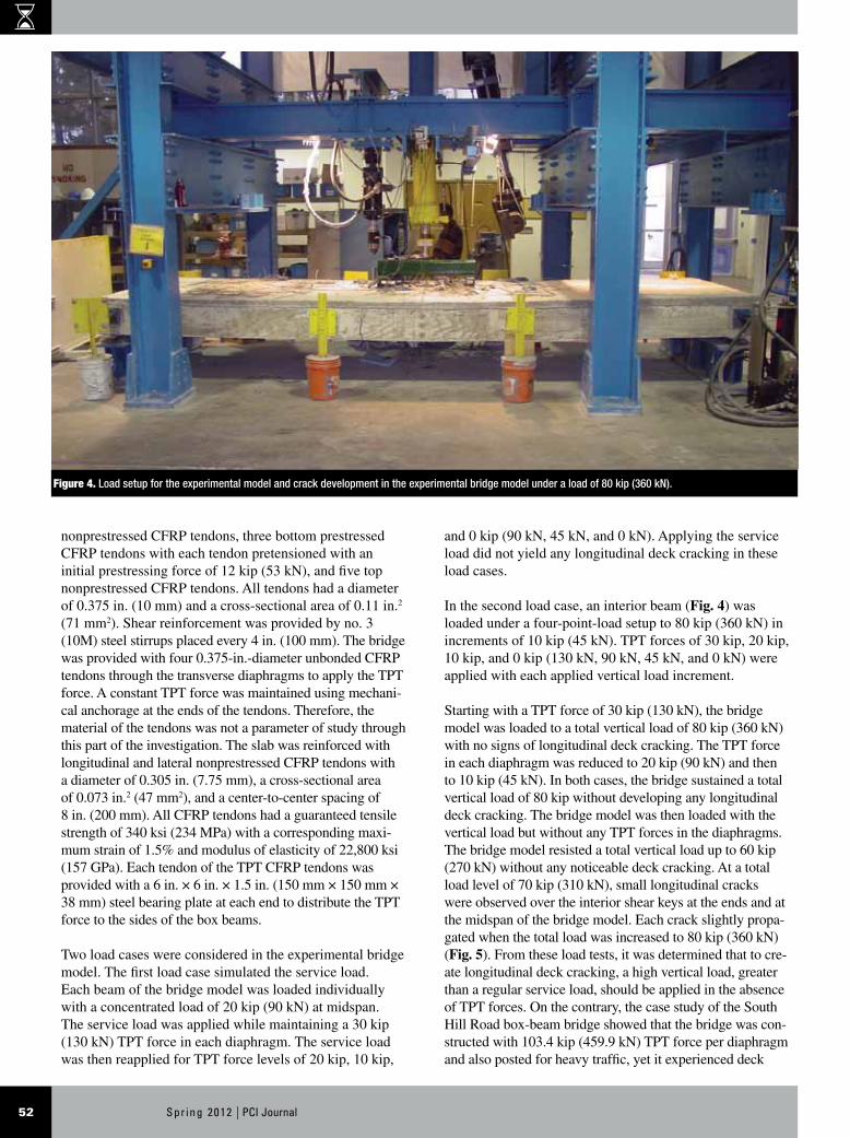
In the second load case, an interior beam (Fig. 4) was loaded under a four-point-load setup to 80 kip (360 kN) in increments of 10 kip (45 kN). TPT forces of 30 kip, 20 kip, 10 kip, and 0 kip (130 kN, 90 kN, 45 kN, and 0 kN) were applied with each applied vertical load increment.
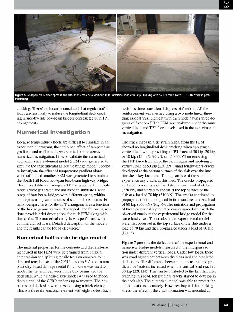
Starting with a TPT force of 30 kip (130 kN), the bridge model was loaded to a total vertical load of 80 kip (360 kN) with no signs of longitudinal deck cracking. The TPT force in each diaphragm was reduced to 20 kip (90 kN) and then to 10 kip (45 kN). In both cases, the bridge sustained a total vertical load of 80 kip without developing any longitudinal deck cracking. The bridge model was then loaded with the vertical load but without any TPT forces in the diaphragms. The bridge model resisted a total vertical load up to 60 kip (270 kN) without any noticeable deck cracking. At a total load level of 70 kip (310 kN), small longitudinal cracks were observed over the interior shear keys at the ends and at the midspan of the bridge model. Each crack slightly propa-gated when the total load was increased to 80 kip (360 kN) (Fig. 5). From these load tests, it was determined that to cre-ate longitudinal deck cracking, a high vertical load, greater than a regular service load, should be applied in the absence of TPT forces. On the contrary, the case study of the South Hill Road box-beam bridge showed that the bridge was con-structed with 103.4 kip (459.9 kN) TPT force per diaphragm and also posted for heavy traffic, yet it experienced deck
nonprestressed CFRP tendons, three bottom prestressed CFRP tendons with each tendon pretensioned with an initial prestressing force of 12 kip (53 kN), and five top nonprestressed CFRP tendons. All tendons had a diameter of 0.375 in. (10 mm) and a cross-sectional area of 0.11 in.2
(71 mm2). Shear reinforcement was provided by no. 3 (10M) steel stirrups placed every 4 in. (100 mm). The bridge was provided with four 0.375-in.-diameter unbonded CFRP tendons through the transverse diaphragms to apply the TPT force. A constant TPT force was maintained using mechani-cal anchorage at the ends of the tendons. Therefore, the material of the tendons was not a parameter of study through this part of the investigation. The slab was reinforced with longitudinal and lateral nonprestressed CFRP tendons with a diameter of 0.305 in. (7.75 mm), a cross-sectional area of 0.073 in.2 (47 mm2), and a center-to-center spacing of 8 in. (200 mm). All CFRP tendons had a guaranteed tensile strength of 340 ksi (234 MPa) with a corresponding maxi-mum strain of 1.5% and modulus of elasticity of 22,800 ksi (157 GPa). Each tendon of the TPT CFRP tendons was provided with a 6 in. × 6 in. × 1.5 in. (150 mm × 150 mm × 38 mm) steel bearing plate at each end to distribute the TPT force to the sides of the box beams.
Two load cases were considered in the experimental bridge model. The first load case simulated the service load. Each beam of the bridge model was loaded individually with a concentrated load of 20 kip (90 kN) at midspan. The service load was applied while maintaining a 30 kip (130 kN) TPT force in each diaphragm. The service load was then reapplied for TPT force levels of 20 kip, 10 kip,
Figure 4. Load setup for the experimental model and crack development in the experimental bridge model under a load of 80 kip (360 kN).
53PCI Journal | Spr ing 2012
cracking. Therefore, it can be concluded that regular traffic loads are less likely to induce the longitudinal deck crack-ing in side-by-side box-beam bridges constructed with TPT arrangements.
Numerical investigation
Because temperature effects are difficult to simulate in an experimental program, the combined effect of temperature gradients and traffic loads was studied in an extensive numerical investigation. First, to validate the numerical approach, a finite element model (FEM) was generated to simulate the experimental half-scale bridge model. Second, to investigate the effect of temperature gradient along with traffic load, another FEM was generated to simulate the South Hill Road two-span box-beam highway bridge. Third, to establish an adequate TPT arrangement, multiple models were generated and analyzed to simulate a wide range of box-beam bridges with different spans, widths, and depths using various sizes of standard box beams. Fi-nally, design charts for the TPT arrangement as a function of the bridge geometry were developed. The following sec-tions provide brief descriptions for each FEM along with the results. The numerical analysis was performed with commercial software. Detailed description of the models and the results can be found elsewhere.12
Numerical half-scale bridge model
The material properties for the concrete and the reinforce-ment used in the FEM were determined from uniaxial compression and splitting tensile tests on concrete cylin-ders and tensile tests of the CFRP tendons.11 A continuum, plasticity-based damage model for concrete was used to model the material behavior in the box beams and the deck slab, while a linear-elastic model was used to model the material of the CFRP tendons up to fracture. The box beams and deck slab were meshed using a brick element. This is a three dimensional element with eight nodes. Each
node has three transitional degrees of freedom. All the reinforcement was meshed using a two-node linear three-dimensional truss element with each node having three de-grees of freedom.13 The FEM was analyzed under the same vertical load and TPT force levels used in the experimental investigation.
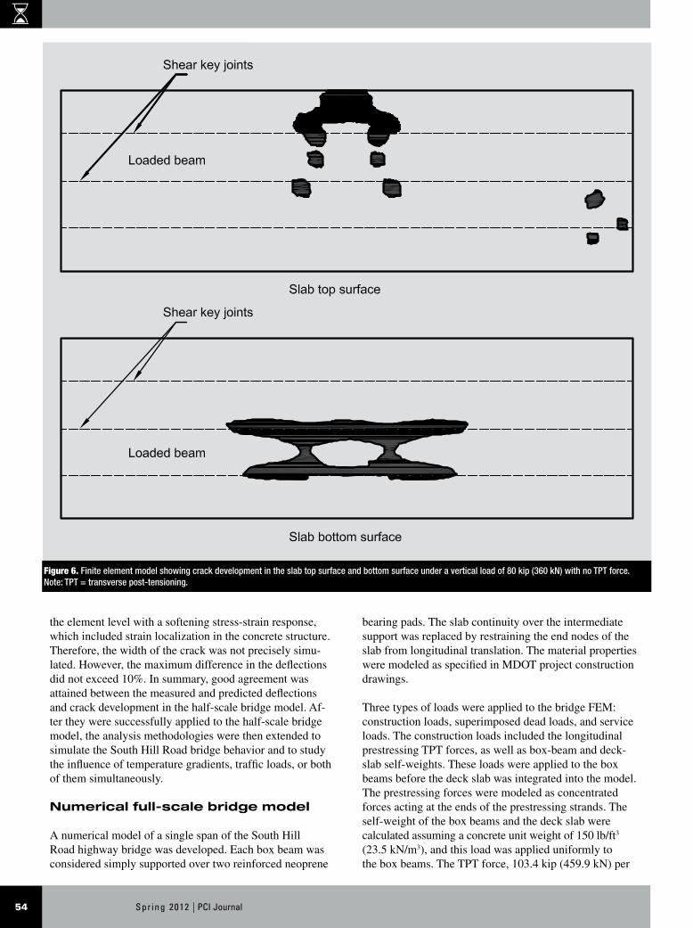
The crack maps (plastic strain maps) from the FEM showed no longitudinal deck cracking when applying a vertical load while providing a TPT force of 30 kip, 20 kip, or 10 kip (130 kN, 90 kN, or 45 kN). When removing the TPT force from all of the diaphragms and applying a vertical load of 50 kip (220 kN), small longitudinal cracks developed at the bottom surface of the slab over the inte-rior shear-key locations. The top surface of the slab did not experience any cracks at this load. The cracks propagated at the bottom surface of the slab at a load level of 60 kip (270 kN) and started to appear at the top surface of the slab at a load of 70 kip (310 kN). The cracks continued to propagate at both the top and bottom surfaces under a load of 80 kip (360 kN) (Fig. 6). The initiation and propagation of these numerically predicted cracks agreed well with the observed cracks in the experimental bridge model for the same load cases. The cracks in the experimental model were first observed at the top surface of the slab under a load of 70 kip and then propagated under a load of 80 kip (Fig. 5).
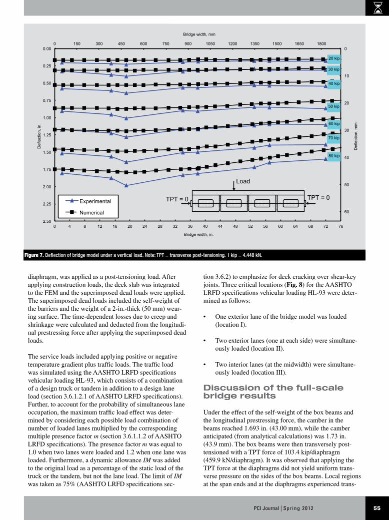
Figure 7 presents the deflections of the experimental and numerical bridge models measured at the midspan sec-tion under different vertical loads. Under low loads, there was good agreement between the measured and predicted deflections. The difference between the measured and pre-dicted deflections increased when the vertical load reached 50 kip (220 kN). This can be attributed to the fact that after reaching this load, longitudinal cracks started to develop in the deck slab. The numerical model was able to predict the crack locations accurately. However, beyond the cracking stress, the effect of the crack formation was modeled at
Figure 5. Midspan crack development and end-span crack development under a vertical load of 80 kip (360 kN) with no TPT force. Note: TPT = transverse post-tensioning.
Spr ing 2012 | PCI Journal54
the element level with a softening stress-strain response, which included strain localization in the concrete structure. Therefore, the width of the crack was not precisely simu-lated. However, the maximum difference in the deflections did not exceed 10%. In summary, good agreement was attained between the measured and predicted deflections and crack development in the half-scale bridge model. Af-ter they were successfully applied to the half-scale bridge model, the analysis methodologies were then extended to simulate the South Hill Road bridge behavior and to study the influence of temperature gradients, traffic loads, or both of them simultaneously.
Numerical full-scale bridge model
A numerical model of a single span of the South Hill Road highway bridge was developed. Each box beam was considered simply supported over two reinforced neoprene
bearing pads. The slab continuity over the intermediate support was replaced by restraining the end nodes of the slab from longitudinal translation. The material properties were modeled as specified in MDOT project construction drawings.
Three types of loads were applied to the bridge FEM: construction loads, superimposed dead loads, and service loads. The construction loads included the longitudinal prestressing TPT forces, as well as box-beam and deck-slab self-weights. These loads were applied to the box beams before the deck slab was integrated into the model. The prestressing forces were modeled as concentrated forces acting at the ends of the prestressing strands. The self-weight of the box beams and the deck slab were calculated assuming a concrete unit weight of 150 lb/ft3 (23.5 kN/m3), and this load was applied uniformly to the box beams. The TPT force, 103.4 kip (459.9 kN) per
Figure 6. Finite element model showing crack development in the slab top surface and bottom surface under a vertical load of 80 kip (360 kN) with no TPT force. Note: TPT = transverse post-tensioning.
55PCI Journal | Spr ing 2012
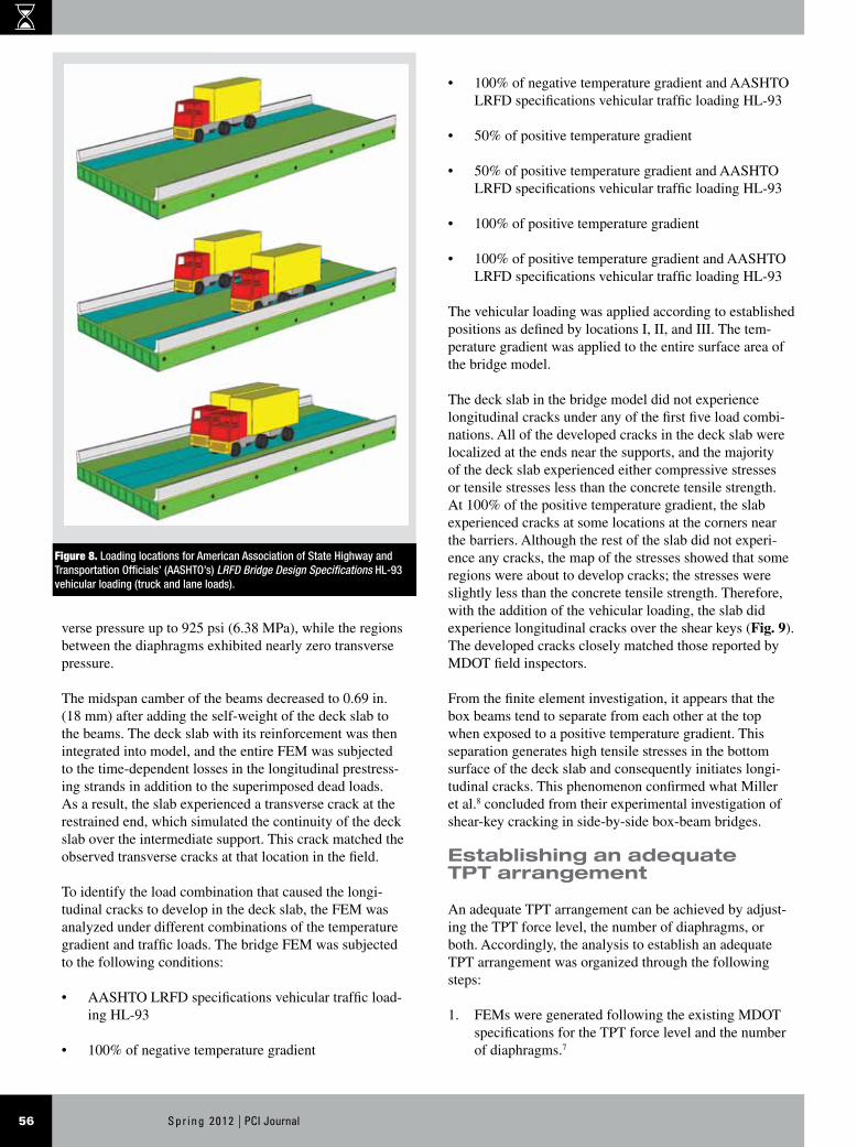
tion 3.6.2) to emphasize for deck cracking over shear-key joints. Three critical locations (Fig. 8) for the AASHTO LRFD specifications vehicular loading HL-93 were deter-mined as follows:
• One exterior lane of the bridge model was loaded (location I).
• Two exterior lanes (one at each side) were simultane-ously loaded (location II).
• Two interior lanes (at the midwidth) were simultane-ously loaded (location III).
Discussion of the full-scale bridge results
Under the effect of the self-weight of the box beams and the longitudinal prestressing force, the camber in the beams reached 1.693 in. (43.00 mm), while the camber anticipated (from analytical calculations) was 1.73 in. (43.9 mm). The box beams were then transversely post-tensioned with a TPT force of 103.4 kip/diaphragm (459.9 kN/diaphragm). It was observed that applying the TPT force at the diaphragms did not yield uniform trans-verse pressure on the sides of the box beams. Local regions at the span ends and at the diaphragms experienced trans-
diaphragm, was applied as a post-tensioning load. After applying construction loads, the deck slab was integrated to the FEM and the superimposed dead loads were applied. The superimposed dead loads included the self-weight of the barriers and the weight of a 2-in.-thick (50 mm) wear-ing surface. The time-dependent losses due to creep and shrinkage were calculated and deducted from the longitudi-nal prestressing force after applying the superimposed dead loads.
The service loads included applying positive or negative temperature gradient plus traffic loads. The traffic load was simulated using the AASHTO LRFD specifications vehicular loading HL-93, which consists of a combination of a design truck or tandem in addition to a design lane load (section 3.6.1.2.1 of AASHTO LRFD specifications). Further, to account for the probability of simultaneous lane occupation, the maximum traffic load effect was deter-mined by considering each possible load combination of number of loaded lanes multiplied by the corresponding multiple presence factor m (section 3.6.1.1.2 of AASHTO LRFD specifications). The presence factor m was equal to 1.0 when two lanes were loaded and 1.2 when one lane was loaded. Furthermore, a dynamic allowance IM was added to the original load as a percentage of the static load of the truck or the tandem, but not the lane load. The limit of IM was taken as 75% (AASHTO LRFD specifications sec-
Figure 7. Deflection of bridge model under a vertical load. Note: TPT = transverse post-tensioning. 1 kip = 4.448 kN.
0
10
20
30
40
50
60
0 150 300 450 600 750 900 1050 1200 1350 1500 1650 1800 0.00
0.25
0.50
0.75
1.00
1.25
1.50
1.75
2.00
2.25
2.50 0 4 8 12 16 20 24 28 32 36 40 44 48 52 56 60 64 68 72 76
Def
lect
ion,
mm
Bridge width, mm D
efle
ctio
n, in
.
Bridge width, in.
Experimental
Numerical
30 kip
40 kip
50 kip
60 kip
70 kip
80 kip
20 kip
Spr ing 2012 | PCI Journal56
• 100% of negative temperature gradient and AASHTO LRFD specifications vehicular traffic loading HL-93
• 50% of positive temperature gradient
• 50% of positive temperature gradient and AASHTO LRFD specifications vehicular traffic loading HL-93
• 100% of positive temperature gradient
• 100% of positive temperature gradient and AASHTO LRFD specifications vehicular traffic loading HL-93
The vehicular loading was applied according to established positions as defined by locations I, II, and III. The tem-perature gradient was applied to the entire surface area of the bridge model.
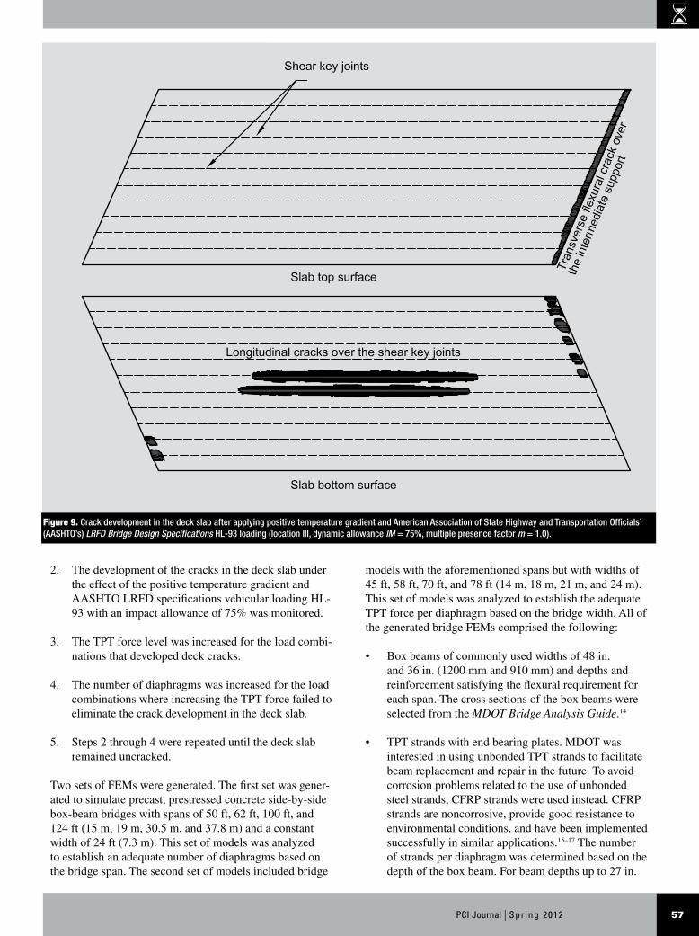
The deck slab in the bridge model did not experience longitudinal cracks under any of the first five load combi-nations. All of the developed cracks in the deck slab were localized at the ends near the supports, and the majority of the deck slab experienced either compressive stresses or tensile stresses less than the concrete tensile strength. At 100% of the positive temperature gradient, the slab experienced cracks at some locations at the corners near the barriers. Although the rest of the slab did not experi-ence any cracks, the map of the stresses showed that some regions were about to develop cracks; the stresses were slightly less than the concrete tensile strength. Therefore, with the addition of the vehicular loading, the slab did experience longitudinal cracks over the shear keys (Fig. 9). The developed cracks closely matched those reported by MDOT field inspectors.
From the finite element investigation, it appears that the box beams tend to separate from each other at the top when exposed to a positive temperature gradient. This separation generates high tensile stresses in the bottom surface of the deck slab and consequently initiates longi-tudinal cracks. This phenomenon confirmed what Miller et al.8 concluded from their experimental investigation of shear-key cracking in side-by-side box-beam bridges.
Establishing an adequate TPT arrangement
An adequate TPT arrangement can be achieved by adjust-ing the TPT force level, the number of diaphragms, or both. Accordingly, the analysis to establish an adequate TPT arrangement was organized through the following steps:
1. FEMs were generated following the existing MDOT specifications for the TPT force level and the number of diaphragms.7
verse pressure up to 925 psi (6.38 MPa), while the regions between the diaphragms exhibited nearly zero transverse pressure.
The midspan camber of the beams decreased to 0.69 in. (18 mm) after adding the self-weight of the deck slab to the beams. The deck slab with its reinforcement was then integrated into model, and the entire FEM was subjected to the time-dependent losses in the longitudinal prestress-ing strands in addition to the superimposed dead loads. As a result, the slab experienced a transverse crack at the restrained end, which simulated the continuity of the deck slab over the intermediate support. This crack matched the observed transverse cracks at that location in the field.
To identify the load combination that caused the longi-tudinal cracks to develop in the deck slab, the FEM was analyzed under different combinations of the temperature gradient and traffic loads. The bridge FEM was subjected to the following conditions:
• AASHTO LRFD specifications vehicular traffic load-ing HL-93
• 100% of negative temperature gradient
Figure 8. Loading locations for American Association of State Highway and Transportation Officials’ (AASHTO’s) LRFD Bridge Design Specifications HL-93 vehicular loading (truck and lane loads).
57PCI Journal | Spr ing 2012
2. The development of the cracks in the deck slab under the effect of the positive temperature gradient and AASHTO LRFD specifications vehicular loading HL-93 with an impact allowance of 75% was monitored.
3. The TPT force level was increased for the load combi-nations that developed deck cracks.
4. The number of diaphragms was increased for the load combinations where increasing the TPT force failed to eliminate the crack development in the deck slab.
5. Steps 2 through 4 were repeated until the deck slab remained uncracked.
Two sets of FEMs were generated. The first set was gener-ated to simulate precast, prestressed concrete side-by-side box-beam bridges with spans of 50 ft, 62 ft, 100 ft, and 124 ft (15 m, 19 m, 30.5 m, and 37.8 m) and a constant width of 24 ft (7.3 m). This set of models was analyzed to establish an adequate number of diaphragms based on the bridge span. The second set of models included bridge
models with the aforementioned spans but with widths of 45 ft, 58 ft, 70 ft, and 78 ft (14 m, 18 m, 21 m, and 24 m). This set of models was analyzed to establish the adequate TPT force per diaphragm based on the bridge width. All of the generated bridge FEMs comprised the following:
• Box beams of commonly used widths of 48 in. and 36 in. (1200 mm and 910 mm) and depths and reinforcement satisfying the flexural requirement for each span. The cross sections of the box beams were selected from the MDOT Bridge Analysis Guide.14
• TPT strands with end bearing plates. MDOT was interested in using unbonded TPT strands to facilitate beam replacement and repair in the future. To avoid corrosion problems related to the use of unbonded steel strands, CFRP strands were used instead. CFRP strands are noncorrosive, provide good resistance to environmental conditions, and have been implemented successfully in similar applications.15–17 The number of strands per diaphragm was determined based on the depth of the box beam. For beam depths up to 27 in.
Figure 9. Crack development in the deck slab after applying positive temperature gradient and American Association of State Highway and Transportation Officials’ (AASHTO’s) LRFD Bridge Design Specifications HL-93 loading (location III, dynamic allowance IM = 75%, multiple presence factor m = 1.0).
Spr ing 2012 | PCI Journal58
(690 mm), one strand was placed at the middepth of the beam. For beam depths of 33 in. (840 mm) and over, two strands were placed at the third points of the beam depth.
• Six-in.-thick (150 mm) deck slab reinforced with single mesh of reinforcement at middepth of the deck slab. Based on earlier investigations,18 a strength of 3000 psi (21 MPa) was considered a fair estimation for the concrete ultimate strength in the deck slab toward the end of service life. In addition, concrete with com-pressive strengths of 4000 psi and 5000 psi (28 MPa and 34 MPa) were also considered. Material properties for each class of concrete were calculated according to AASHTO LRFD specifications section 5.4.2.
• Elastomeric bearing pads for simply supported condi-tions.
• Nonshrink grout material in the shear keys connecting the adjacent box beams. The grout material was mod-eled as a friction interface element between the sides of the box beams.
Analysis, results, and discussion of TPT arrangements
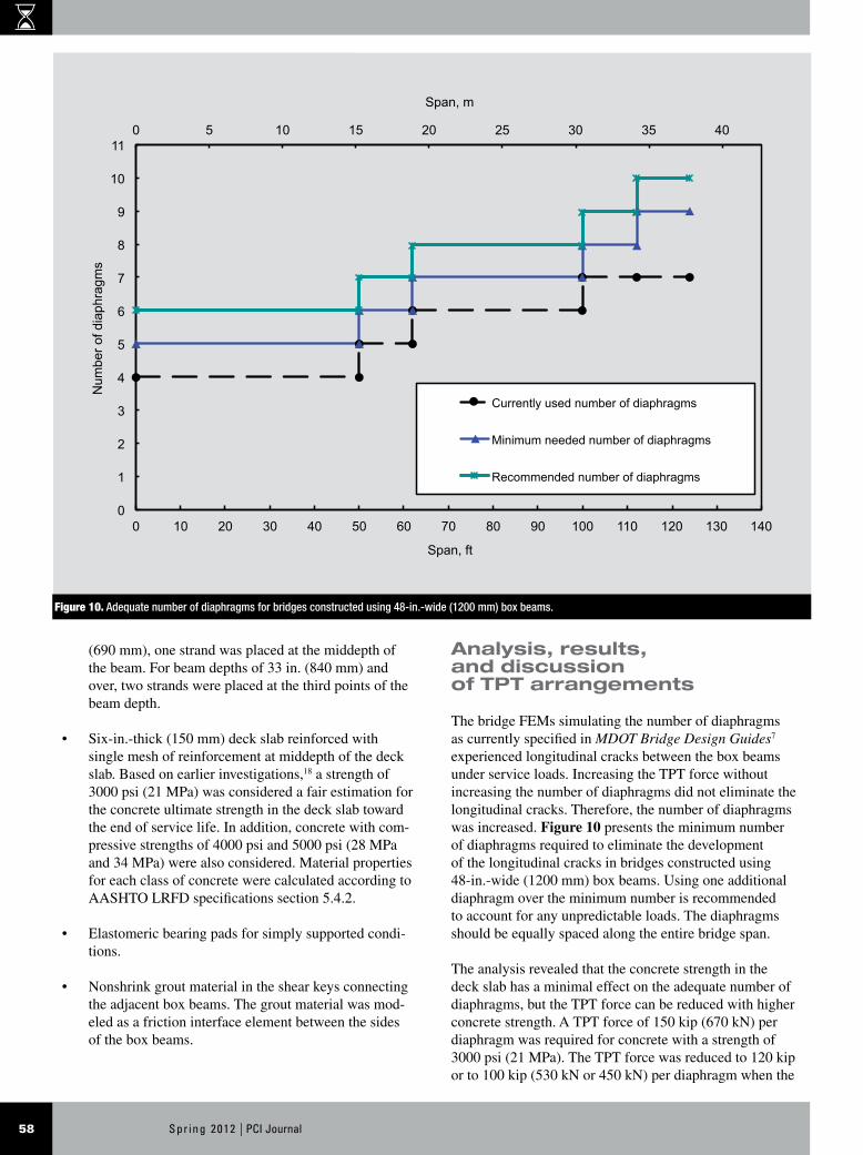
The bridge FEMs simulating the number of diaphragms as currently specified in MDOT Bridge Design Guides7 experienced longitudinal cracks between the box beams under service loads. Increasing the TPT force without increasing the number of diaphragms did not eliminate the longitudinal cracks. Therefore, the number of diaphragms was increased. Figure 10 presents the minimum number of diaphragms required to eliminate the development of the longitudinal cracks in bridges constructed using 48-in.-wide (1200 mm) box beams. Using one additional diaphragm over the minimum number is recommended to account for any unpredictable loads. The diaphragms should be equally spaced along the entire bridge span.
The analysis revealed that the concrete strength in the deck slab has a minimal effect on the adequate number of diaphragms, but the TPT force can be reduced with higher concrete strength. A TPT force of 150 kip (670 kN) per diaphragm was required for concrete with a strength of 3000 psi (21 MPa). The TPT force was reduced to 120 kip or to 100 kip (530 kN or 450 kN) per diaphragm when the
Figure 10. Adequate number of diaphragms for bridges constructed using 48-in.-wide (1200 mm) box beams.
0 5 10 15 20 25 30 35 40
0
1
2
3
4
5
6
7
8
9
10
11
0 10 20 30 40 50 60 70 80 90 100 110 120 130 140
Span, m N
umbe
r of d
iaph
ragm
s
Span, ft
Currently used number of diaphragms
Minimum needed number of diaphragms
Recommended number of diaphragms
59PCI Journal | Spr ing 2012
Conclusion
This investigation was conducted with the main objec-tive of understanding the problem of longitudinal deck cracking in side-by-side box-beam bridges. Field observa-tions combined with experimental data were employed to identify the performance of box-beam bridges under the combined effects of thermal and traffic loads. In addition, a numerical investigation was conducted to simulate the be-havior of box-beam bridges subjected to different realistic load combinations and to evaluate the relationship between the bridge geometry and the minimum TPT arrangement required to eliminate longitudinal deck cracking. Fur-thermore, and as a practical application for the findings, an adequate number of diaphragms and an appropriate TPT force per diaphragm were established for box-beam bridges constructed in Michigan and other regions with similar thermal and traffic conditions. The findings of this study support the following conclusions:
• Traffic loads do not appear to be the major factor in developing longitudinal cracks in the slab. The posi-tive temperature gradient is the major contributing fac-tor in the initiation of the longitudinal deck cracks in
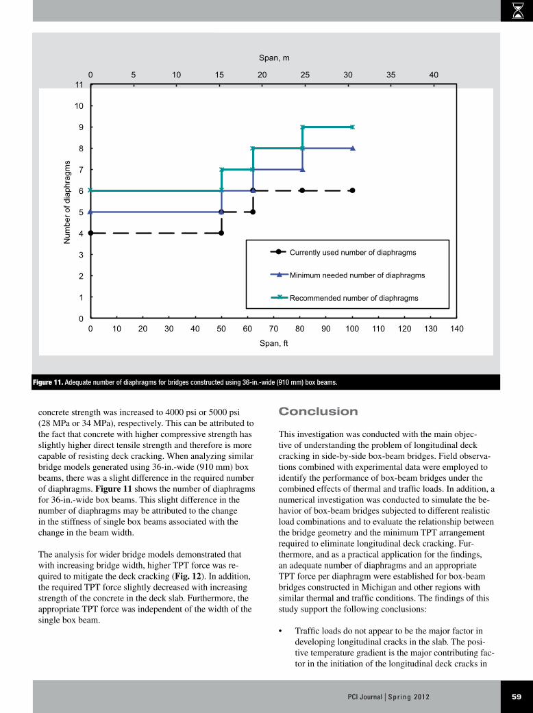
concrete strength was increased to 4000 psi or 5000 psi (28 MPa or 34 MPa), respectively. This can be attributed to the fact that concrete with higher compressive strength has slightly higher direct tensile strength and therefore is more capable of resisting deck cracking. When analyzing similar bridge models generated using 36-in.-wide (910 mm) box beams, there was a slight difference in the required number of diaphragms. Figure 11 shows the number of diaphragms for 36-in.-wide box beams. This slight difference in the number of diaphragms may be attributed to the change in the stiffness of single box beams associated with the change in the beam width.
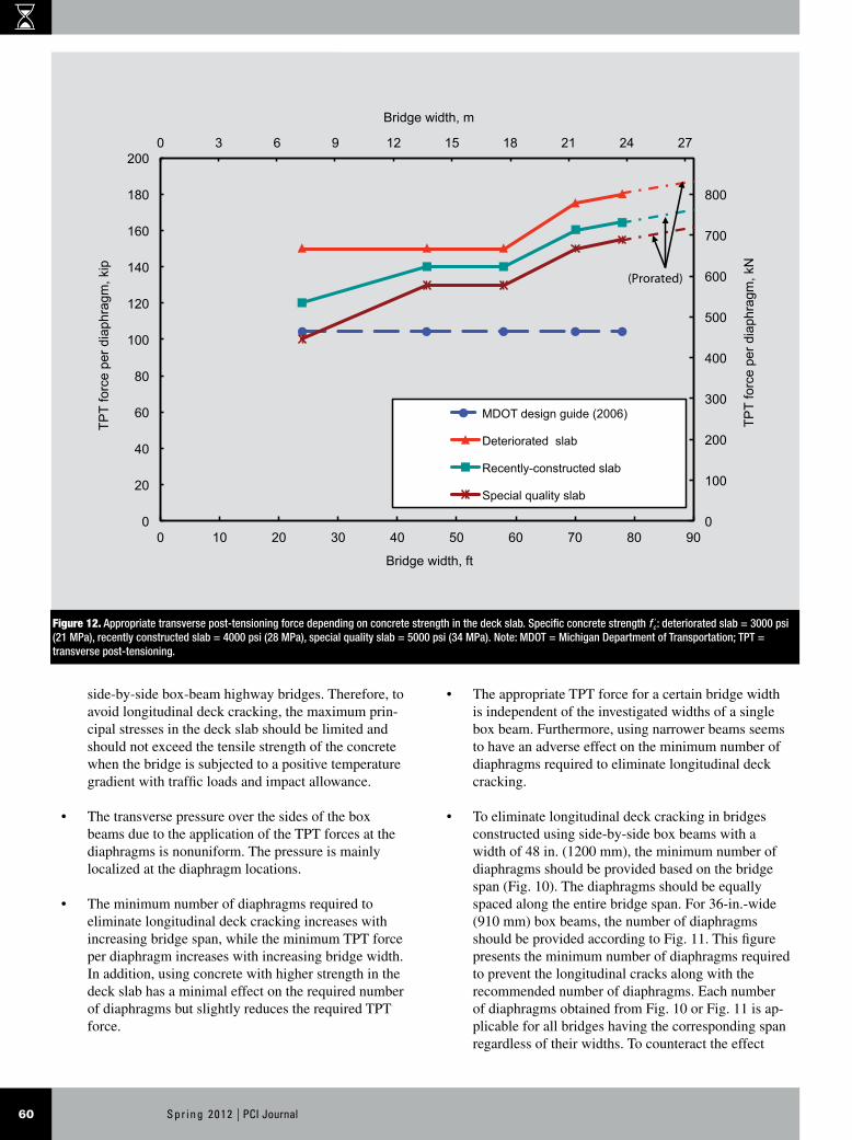
The analysis for wider bridge models demonstrated that with increasing bridge width, higher TPT force was re-quired to mitigate the deck cracking (Fig. 12). In addition, the required TPT force slightly decreased with increasing strength of the concrete in the deck slab. Furthermore, the appropriate TPT force was independent of the width of the single box beam.
Figure 11. Adequate number of diaphragms for bridges constructed using 36-in.-wide (910 mm) box beams.
0 5 10 15 20 25 30 35 40
0
1
2
3
4
5
6
7
8
9
10
11
0 10 20 30 40 50 60 70 80 90 100 110 120 130 140
Span, m N
umbe
r of d
iaph
ragm
s
Span, ft
Currently used number of diaphragms
Minimum needed number of diaphragms
Recommended number of diaphragms
Spr ing 2012 | PCI Journal60
• The appropriate TPT force for a certain bridge width is independent of the investigated widths of a single box beam. Furthermore, using narrower beams seems to have an adverse effect on the minimum number of diaphragms required to eliminate longitudinal deck cracking.
• To eliminate longitudinal deck cracking in bridges constructed using side-by-side box beams with a width of 48 in. (1200 mm), the minimum number of diaphragms should be provided based on the bridge span (Fig. 10). The diaphragms should be equally spaced along the entire bridge span. For 36-in.-wide (910 mm) box beams, the number of diaphragms should be provided according to Fig. 11. This figure presents the minimum number of diaphragms required to prevent the longitudinal cracks along with the recommended number of diaphragms. Each number of diaphragms obtained from Fig. 10 or Fig. 11 is ap-plicable for all bridges having the corresponding span regardless of their widths. To counteract the effect
side-by-side box-beam highway bridges. Therefore, to avoid longitudinal deck cracking, the maximum prin-cipal stresses in the deck slab should be limited and should not exceed the tensile strength of the concrete when the bridge is subjected to a positive temperature gradient with traffic loads and impact allowance.
• The transverse pressure over the sides of the box beams due to the application of the TPT forces at the diaphragms is nonuniform. The pressure is mainly localized at the diaphragm locations.
• The minimum number of diaphragms required to eliminate longitudinal deck cracking increases with increasing bridge span, while the minimum TPT force per diaphragm increases with increasing bridge width. In addition, using concrete with higher strength in the deck slab has a minimal effect on the required number of diaphragms but slightly reduces the required TPT force.
Figure 12. Appropriate transverse post-tensioning force depending on concrete strength in the deck slab. Specific concrete strength f 'c : deteriorated slab = 3000 psi (21 MPa), recently constructed slab = 4000 psi (28 MPa), special quality slab = 5000 psi (34 MPa). Note: MDOT = Michigan Department of Transportation; TPT = transverse post-tensioning.
0
100
200
300
400
500
600
700
800
0 3 6 9 12 15 18 21 24 27
0
20
40
60
80
100
120
140
160
180
200
0 10 20 30 40 50 60 70 80 90
TPT
forc
e pe
r dia
phra
gm, k
N
Bridge width, m TP
T fo
rce
per d
iaph
ragm
, kip
Bridge width, ft
MDOT design guide (2006)
Deteriorated slab
Recently-constructed slab
Special quality slab
(Prorated)
61PCI Journal | Spr ing 2012
6. El-Remaily, A., M. K. Tadros, T. Yamane, and G. Krause. 1996. Transverse Design of Adjacent Precast Prestressed Concrete Box Girder Bridges. PCI Jour-nal, V. 41, No. 4 (July–August): pp. 96–112.
7. Michigan Department of Transportation (MDOT) Construction and Technology Support Area. 2006. MDOT Bridge Design Guides. Lansing, MI: MDOT.
8. Miller, R. A., G. M. Hlavacs, T. Long, and A. Greuel. 1999. Full-Scale Testing of Shear Keys for Adjacent Box Girder Bridges. PCI Journal, V. 44, No. 6 (No-vember–December): pp. 80–90.
9. Hlavacs, G., T. Long, R. Miller, and T. Baseheart. 1997. Nondestructive Determination of Response of Shear Keys to Environmental and Structural Cyclic Loading. Transportation Research Record, V. 1574: pp. 18–24.
10. American Association of State Highway and Trans-portation Officials (AASHTO). 2004. AASHTO LRFD Bridge Design Specifications. 3rd ed. Washington, DC: AASHTO.
11. Labib, M. 2007. Effect of Transverse Post-tensioning on Load Distribution in Side-by-Side CFRP Pre-stressed Concrete Box Beam Bridges. Master’s thesis, Civil Engineering Department, Lawrence Technologi-cal University, Southfield, MI.
12. Bebawy, M. 2007. Optimum Transverse Post-tension-ing Arrangement for Side-by-side Box Beam Bridges. Master’s thesis, Civil Engineering Department, Law-rence Technological University, Southfield, MI.
13. Hibbitt, Karlsson & Sorensen Inc. 2006. ABAQUS 6.6 User’s Manual. Pawtucket, RI: Hibbitt, Karlsson & Sorensen Inc.
14. Michigan Department of Transportation Construction and Technology Support Area. 2005. MDOT Bridge Analysis Guide. Lansing, MI: MDOT.
15. Grace, N. F., and G. Abdel-Sayed. 2000. Behavior of Carbon Fiber Reinforced Prestressed Concrete Skew Bridge. ACI Structural Journal, V. 97, No. 1 (January–February): pp. 26–34.
16. Grace, N. F., F. C. Navarre, R. B. Nacey, W. Bo-nus, and L. Collavino. 2002. Design-Construction of Bridge Street Bridge—First CFRP Bridge in the United States. PCI Journal, V. 47, No. 5 (September–October): pp. 20–35.
of increasing the bridge width on the lateral tensile stresses, the TPT force should be adjusted according to Fig. 12.
• Charts shown in Fig. 10, 11, and 12 are valid for the design of the TPT arrangement in side-by-side box-beam bridges constructed in Michigan and regions with similar or less harsh thermal and traffic condi-tions. These charts need to be evaluated for other re-gions with significant difference in thermal and traffic conditions.
Acknowledgments
This investigation was sponsored by the Michigan Depart-ment of Transportation (MDOT) (contract 2004-0105), the Michigan Economic Development Corp. (contract 085P7200156), the National Science Foundation (award CMS0408593), and the U.S. Department of Transportation (contract DTOS59-06-G00030). The authors gratefully acknowledge their support. The results and recommenda-tions of this investigation are being deployed in the design and construction of three box-beam bridges over Southfield Freeway, M-39, under the supervision of the MDOT Metro Region Office and the research team at Lawrence Techno-logical University. The experimental work in the study was performed by Moheb Labib at Lawrence Technological University. The authors appreciate and acknowledge his assistance.
References
1. Michigan Department of Transportation Construction and Technology Division. 2005. Box-Beam Concerns Found under the Bridge. C & T Research Record, No. 102 (September): pp. 1–4.
2. Lall, J., S. Alampalli, and E. F. Di Cocco. 1998. Performance of Full-Depth Shear Keys in Adjacent Prestressed Box Beam Bridges. PCI Journal, V. 43, No. 2 (March–April): pp. 72–79.
3. Gilberston, C., U. Attanayake, T. Ahlborn, and H. Aktan. 2006. Prestressed Concrete Box-Beam Bridge Performance: Condition Assessment and Design Analysis. 06-2432. Washington, DC: Transportation Research Board.
4. Huckelbridge, A., H. El-Esnawi, and F. Moses. 1995. Shear Key Performance in Multi Beam Box Girder Bridges. Journal of Performance of Constructed Fa-cilities, V. 9, No. 4 (November): pp. 271–285.
5. Bakht, B., L. G. Jaeger, and M. S. Cheung. 1983. Transverse Shear in Multi Beam Bridges. Journal of Structural Engineering, V. 109, No. 4 (April): pp. 936–949.
Spr ing 2012 | PCI Journal62
17. Grace, N. F., T. Enomoto, and K. Yagi. 2002. Behavior of CFCC and CFRP Leadline Prestressing Systems in Bridge Construction. PCI Journal, V. 47, No. 3 (May–June): pp. 90–103.
18. Kwasniewski, L., M. M. Szerszen, and A. S. Nowak. 2000. Sensitivity Analysis for Slab-on-Girder Bridges. Paper PMC2000-316. In Proceedings of the 8th ASCE Joint Specialty Conference on Probabilistic Mechanics and Structural Reliability. Kareem, Haldar, Spencer, and Johnson, eds. Notre Dame, IN: University of Notre Dame. CD-ROM.
Notation
fcl = specific concrete strength
IM = dynamic allowance
m = multiple presence factor

63PCI Journal | Spr ing 2012
About the authors
Nabil F. Grace, PhD, P.E., is the dean of the College of Engineer-ing and a University Distin-guished Professor at Lawrence Technological University in Southfield, Mich. He is also the director of the Center for Innova-
tive Materials Research in Southfield.
Elin A. Jensen, PhD, is the associate dean of Graduate Studies and Research for the College of Engineering at Lawrence Technological University.
Mena R. Bebawy, PhD, is a postdoctoral research fellow for the Department of Civil Engineer-ing at Lawrence Technological University.
Abstract
While side-by-side box-beam bridges have numerous structural advantages, a serious drawback for this type of bridge is the longitudinal deck cracking over the shear keys. These cracks are observed as early as a few years after initial construction, even where transverse post-tensioning is applied. Associated distresses are
well documented in the literature. Two hypotheses were established: longitudinal deck cracking in side-by-side box-beam bridges may be mitigated through an optimized transverse post-tensioning arrangement and traffic is not the sole load factor controlling longi-tudinal deck cracking. This broad study, encompassing field observations as well as experimental and numeri-cal investigations, demonstrates that a transverse post-tensioning system can be determined as a function of bridge geometry such that deck cracking due to temperature and traffic loads is mitigated. The recom-mended transverse post-tensioning system is defined by the number of diaphragms and the force applied at each diaphragm.
Keywords
Box beam, bridge, cracking, deck, diaphragm, post-tensioning, shear key.
Review policy
This paper was reviewed in accordance with the Precast/Prestressed Concrete Institute’s peer-review process.
Reader comments
Please address any reader comments to journal@pci .org or Precast/Prestressed Concrete Institute, c/o PCI Journal 200 W. Adams St., Suite 2100, Chicago, IL 60606. J