
ISO 10816-5 E - blueym.comblueym.com/uploads/2016/06/211001586031.pdf · ISO 10816-5:2000(E) © ISO...
26
Reference number ISO 10816-5:2000(E) © ISO 2000 INTERNATIONAL STANDARD ISO 10816-5 First edition 2000-04-01 Mechanical vibration — Evaluation of machine vibration by measurements on non-rotating parts — Part 5: Machine sets in hydraulic power generating and pumping plants Vibrations mécaniques — Évaluation des vibrations des machines par mesurages sur les parties non tournantes — Partie 5: Groupes générateurs de puissance et installations de pompage hydrauliques Normen-Download-Beuth-Alstom Power Generation AG-KdNr.5281078-LfNr.2488512001-2004-08-09 15:10
Transcript of ISO 10816-5 E - blueym.comblueym.com/uploads/2016/06/211001586031.pdf · ISO 10816-5:2000(E) © ISO...
Reference numberISO 10816-5:2000(E)
© ISO 2000
INTERNATIONALSTANDARD
ISO10816-5
First edition2000-04-01
Mechanical vibration — Evaluationof machine vibration by measurementson non-rotating parts —
Part 5:Machine sets in hydraulic power generatingand pumping plants
Vibrations mécaniques — Évaluation des vibrations des machines parmesurages sur les parties non tournantes —
Partie 5: Groupes générateurs de puissance et installations de pompagehydrauliques
B55EB1B3C7662F79D1B59483A53B9F2F82C98BEEB793928A78C467B382C61E866DE10E2F87F34E8D91B869B14603ECBBAD0B89D103BC2D07EB7876E5628240DE1A26F7E8117640E54B2D000E0CA0206AF0BD6437BCB1BF9FF7746AD35C9469
No
rmen
-Do
wn
load
-Beu
th-A
lsto
m P
ow
er G
ener
atio
n A
G-K
dN
r.52
8107
8-L
fNr.
2488
5120
01-2
004-
08-0
9 15
:10
ISO 10816-5:2000(E)
PDF disclaimer
This PDF file may contain embedded typefaces. In accordance with Adobe's licensing policy, this file may be printed or viewed but shall notbe edited unless the typefaces which are embedded are licensed to and installed on the computer performing the editing. In downloading thisfile, parties accept therein the responsibility of not infringing Adobe's licensing policy. The ISO Central Secretariat accepts no liability in thisarea.
Adobe is a trademark of Adobe Systems Incorporated.
Details of the software products used to create this PDF file can be found in the General Info relative to the file; the PDF-creation parameterswere optimized for printing. Every care has been taken to ensure that the file is suitable for use by ISO member bodies. In the unlikely eventthat a problem relating to it is found, please inform the Central Secretariat at the address given below.
© ISO 2000
All rights reserved. Unless otherwise specified, no part of this publication may be reproduced or utilized in any form or by any means, electronicor mechanical, including photocopying and microfilm, without permission in writing from either ISO at the address below or ISO's member bodyin the country of the requester.
ISO copyright officeCase postale 56 � CH-1211 Geneva 20Tel. + 41 22 749 01 11Fax + 41 22 734 10 79E-mail [email protected] www.iso.ch
Printed in Switzerland
ii © ISO 2000 – All rights reserved
B55EB1B3C7662F79D1B59483A53B9F2F82C98BEEB793928A78C467B382C61E866DE10E2F87F34E8D91B869B14603ECBBAD0B89D103BC2D07EB7876E5628240DE1A26F7E8117640E54B2D000E0CA0206AF0BD6437BCB1BF9FF7746AD35C9469
No
rmen
-Do
wn
load
-Beu
th-A
lsto
m P
ow
er G
ener
atio
n A
G-K
dN
r.52
8107
8-L
fNr.
2488
5120
01-2
004-
08-0
9 15
:10
ISO 10816-5:2000(E)
© ISO 2000 – All rights reserved iii
Contents Page
Foreword....................................................................................................................... ..............................................iv
Introduction ................................................................................................................... ..............................................v
1 Scope ......................................................................................................................... .....................................1
2 Normative references ........................................................................................................... .........................2
3 Machine arrangements........................................................................................................... .......................2
4 Measurement procedures and conditions ............................................................................................ ......74.1 General..................................................................................................................... .......................................74.2 Measurement type ............................................................................................................. ............................84.3 Measurement locations and directions ........................................................................................... ............84.4 Measurement equipment ........................................................................................................ ......................94.5 Operational conditions....................................................................................................... .........................10
5 Evaluation.................................................................................................................... .................................105.1 General..................................................................................................................... .....................................105.2 Criterion I: Vibration magnitude............................................................................................... ..................105.3 Evaluation zone limits ........................................................................................................ .........................105.3.1 Turbine operating conditions ................................................................................................ .....................105.3.2 Pump operating conditions ................................................................................................... .....................115.3.3 Special operating conditions................................................................................................ ......................115.3.4 Axial vibration ............................................................................................................ ..................................115.4 Criterion II: Change in vibration magnitude...................................................................................... ........125.5 Operational limits........................................................................................................... ..............................125.5.1 General................................................................................................................... .......................................125.5.2 Setting of ALARMS........................................................................................................... ...........................125.5.3 Setting of TRIPS............................................................................................................ ...............................135.5.4 Special operating conditions................................................................................................ ......................135.6 Supplementary procedures/criteria ............................................................................................ ...............135.7 Evaluation based on vibration vector information................................................................................. ..13
Annex A (normative) Evaluation zone boundaries ................................................................................................14
Annex B (informative) Special features of bearing housing vibration of hydraulic machine sets ...................16
Annex C (informative) Analysis procedure and applied regression technique..................................................18
Bibliography ................................................................................................................... ...........................................19
B55EB1B3C7662F79D1B59483A53B9F2F82C98BEEB793928A78C467B382C61E866DE10E2F87F34E8D91B869B14603ECBBAD0B89D103BC2D07EB7876E5628240DE1A26F7E8117640E54B2D000E0CA0206AF0BD6437BCB1BF9FF7746AD35C9469
No
rmen
-Do
wn
load
-Beu
th-A
lsto
m P
ow
er G
ener
atio
n A
G-K
dN
r.52
8107
8-L
fNr.
2488
5120
01-2
004-
08-0
9 15
:10
ISO 10816-5:2000(E)
iv © ISO 2000 – All rights reserved
Foreword
ISO (the International Organization for Standardization) is a worldwide federation of national standards bodies (ISOmember bodies). The work of preparing International Standards is normally carried out through ISO technicalcommittees. Each member body interested in a subject for which a technical committee has been established hasthe right to be represented on that committee. International organizations, governmental and non-governmental, inliaison with ISO, also take part in the work. ISO collaborates closely with the International ElectrotechnicalCommission (IEC) on all matters of electrotechnical standardization.
International Standards are drafted in accordance with the rules given in the ISO/IEC Directives, Part 3.
Draft International Standards adopted by the technical committees are circulated to the member bodies for voting.Publication as an International Standard requires approval by at least 75 % of the member bodies casting a vote.
Attention is drawn to the possibility that some of the elements of this part of ISO 10816 may be the subject ofpatent rights. ISO shall not be held responsible for identifying any or all such patent rights.
International Standard ISO 10816-5 was prepared by Technical Committee ISO/TC 108, Mechanical vibration andshock, Subcommittee SC 2, Measurement and evaluation of mechanical vibration and shock as applied tomachines, vehicles and structures.
ISO 10816 consists of the following parts, under the general title Mechanical vibration — Evaluation of machinevibration by measurements on non-rotating parts:
� Part 1: General guidelines
� Part 2: Large land-based steam turbine generator sets in excess of 50 MW
� Part 3: Industrial machines with nominal power above 15 kW and nominal speeds between 120 r/min and15 000 r/min when measured in situ
� Part 4: Gas turbine driven sets excluding aircraft derivatives
� Part 5: Machine sets in hydraulic power generating and pumping plants
� Part 6: Reciprocating machines with power ratings above 100 kW
Annex A forms a normative part of this part of ISO 10816. Annexes B and C are for information only.
B55EB1B3C7662F79D1B59483A53B9F2F82C98BEEB793928A78C467B382C61E866DE10E2F87F34E8D91B869B14603ECBBAD0B89D103BC2D07EB7876E5628240DE1A26F7E8117640E54B2D000E0CA0206AF0BD6437BCB1BF9FF7746AD35C9469
No
rmen
-Do
wn
load
-Beu
th-A
lsto
m P
ow
er G
ener
atio
n A
G-K
dN
r.52
8107
8-L
fNr.
2488
5120
01-2
004-
08-0
9 15
:10
ISO 10816-5:2000(E)
© ISO 2000 – All rights reserved v
Introduction
ISO 10816-1 is the basic document which describes the general requirements for evaluating vibration of variousmachine types when the vibration measurements are made on non-rotating parts. This part of ISO 10816 providesspecific guidance for assessing the severity of vibration measured at the bearings, bearing pedestals or bearinghousings of machine sets in hydraulic power generating and pumping plants when measurements are made in situ.
Two criteria are provided for assessing the machine vibration. One criterion considers the magnitude of observedvibration; the second considers changes in the magnitudes. It must be recognized, however, that these two criteria donot form the only basis for judging the severity of vibration. For most machine types it is also common to judge thevibration based on measurements taken on the rotating shaft. Shaft vibration measurement requirements and criteriaare addressed in separate documents, ISO 7919-1 and ISO 7919-5.
B55EB1B3C7662F79D1B59483A53B9F2F82C98BEEB793928A78C467B382C61E866DE10E2F87F34E8D91B869B14603ECBBAD0B89D103BC2D07EB7876E5628240DE1A26F7E8117640E54B2D000E0CA0206AF0BD6437BCB1BF9FF7746AD35C9469
No
rmen
-Do
wn
load
-Beu
th-A
lsto
m P
ow
er G
ener
atio
n A
G-K
dN
r.52
8107
8-L
fNr.
2488
5120
01-2
004-
08-0
9 15
:10
INTERNATIONAL STANDARD ISO 10816-5:2000(E)
© ISO 2000 – All rights reserved 1
Mechanical vibration — Evaluation of machine vibration bymeasurements on non-rotating parts —
Part 5:Machine sets in hydraulic power generating and pumping plants
1 Scope
This part of ISO 10816 gives guidelines for applying bearing housing vibration evaluation criteria measured undernormal operating conditions at the bearings, bearing pedestals or bearing housings of the main machine sets inhydraulic power generating and pumping plants. These guidelines are presented in terms of both steady-state runningvibration and any amplitude changes which may occur in these steady values. The numerical values specified are notintended to serve as the only basis for vibration evaluation, since, in general, the vibratory condition of a machine isassessed by consideration of both the bearing housing vibration and the associated shaft vibration (see introduction ofISO 10816-1 and ISO 7919-1).
This part of ISO 10816 is applicable to machine sets in hydraulic power generating and pumping plants where thehydraulic machines have speeds from 60 r/min to 1800 r/min, shell or shoe type sleeve bearings and a main enginepower of 1 MW and more. The position of the shaft line may be vertical, horizontal or at an arbitrary angle betweenthese two directions.
Machine sets covered by this part of ISO 10816 may be combined from
� hydraulic turbines and generators,
� pumps and electrical machines operating as motors, or
� pump-turbines and motor-generators.
Auxiliary equipment (e.g. starting turbines or exciters lying in the shaft line) is included. Evaluation criteria are atpresent only given for the main bearings of the machine set.
This part of ISO 10816 is applicable also to single turbines or pumps connected to generators or electrical motorsover gears or/and radially flexible couplings. However, electrical machines of this type should in principal be evaluatedaccording to the criteria specified in ISO 10816-3.
This part of ISO 10816 is not applicable to the following:
� pumps in thermal power plants or industrial installations (for these machines, see ISO 10816-3);
� hydraulic machines or machine sets having rolling element bearings.
Consistent with clause 1 of ISO 10816-1:1995, bearing housing vibration of machine sets in hydraulic powergenerating and pumping plants may be determined with regard to following tasks:
� task A: monitoring changes in vibrational behaviour;
� task B: prevention of excessive kinetic load.
B55EB1B3C7662F79D1B59483A53B9F2F82C98BEEB793928A78C467B382C61E866DE10E2F87F34E8D91B869B14603ECBBAD0B89D103BC2D07EB7876E5628240DE1A26F7E8117640E54B2D000E0CA0206AF0BD6437BCB1BF9FF7746AD35C9469
No
rmen
-Do
wn
load
-Beu
th-A
lsto
m P
ow
er G
ener
atio
n A
G-K
dN
r.52
8107
8-L
fNr.
2488
5120
01-2
004-
08-0
9 15
:10
ISO 10816-5:2000(E)
2 © ISO 2000 – All rights reserved
The criteria are applicable mainly for the vibration produced by the machine set itself. Special considerations shouldbe made when necessary for vibration transmitted to the machine set from external sources.
2 Normative references
The following normative documents contain provisions which, through reference in this text, constitute provisions ofthis part of ISO 10816. For dated references, subsequent amendments to, or revisions of, any of these publicationsdo not apply. However, parties to agreements based on this part of ISO 10816 are encouraged to investigate thepossibility of applying the most recent editions of the normative documents indicated below. For undatedreferences, the latest edition of the normative document referred to applies. Members of ISO and IEC maintainregisters of currently valid International Standards.
ISO 10816-1:1995, Mechanical vibration — Evaluation of machine vibration by measurements on non-rotatingparts — Part 1: General guidelines.
IEC 60994, Guide for field measurement of vibrations and pulsations in hydraulic machines (turbines, storagepumps and pump-turbines).
3 Machine arrangements
Significant differences in design and arrangement of hydraulic machine sets require a separation into four principalgroups with regard to the radial bearing stiffness, as follows.
Group 1 : Horizontal machine sets with pedestal or end-shield bearings mounted on a rigid foundation, usually withoperational speeds of above 300 r/min.
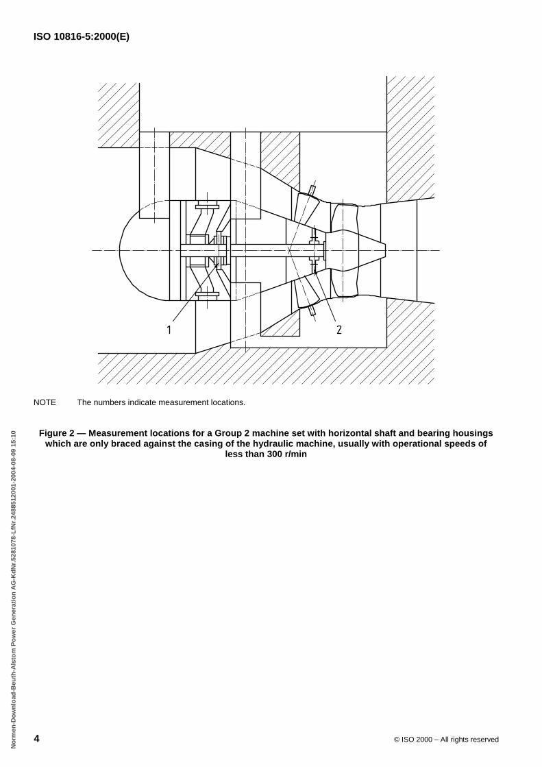
Group 2 : Horizontal machine sets with bearing housings which are only braced against the casing of the hydraulicmachine, usually with operational speeds of less than 300 r/min.
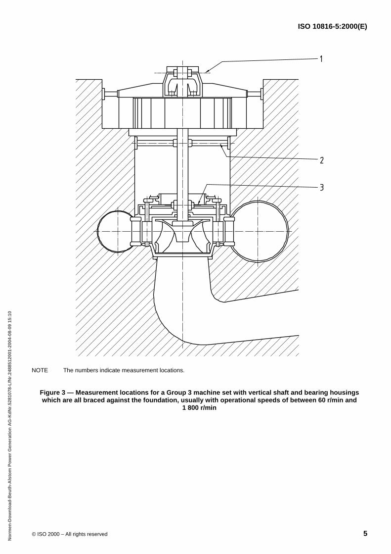
Group 3 : Vertical machine sets with bearing housings which are all braced against the foundation, usually withoperational speeds of between 60 r/min and 1 800 r/min.
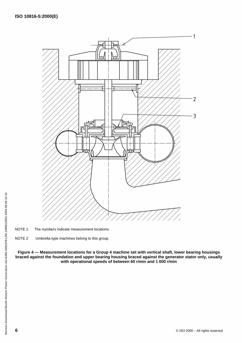
Group 4 : Vertical machine sets with lower bearing housings braced against the foundation and upper bearinghousings braced against the generator stator only, usually with operational speeds of between 60 r/min and1 000 r/min.
NOTE Umbrella-type machines belong to Group 4.
Figures 1 to 4 show examples for each group.
B55EB1B3C7662F79D1B59483A53B9F2F82C98BEEB793928A78C467B382C61E866DE10E2F87F34E8D91B869B14603ECBBAD0B89D103BC2D07EB7876E5628240DE1A26F7E8117640E54B2D000E0CA0206AF0BD6437BCB1BF9FF7746AD35C9469
No
rmen
-Do
wn
load
-Beu
th-A
lsto
m P
ow
er G
ener
atio
n A
G-K
dN
r.52
8107
8-L
fNr.
2488
5120
01-2
004-
08-0
9 15
:10
ISO 10816-5:2000(E)
© ISO 2000 – All rights reserved 3
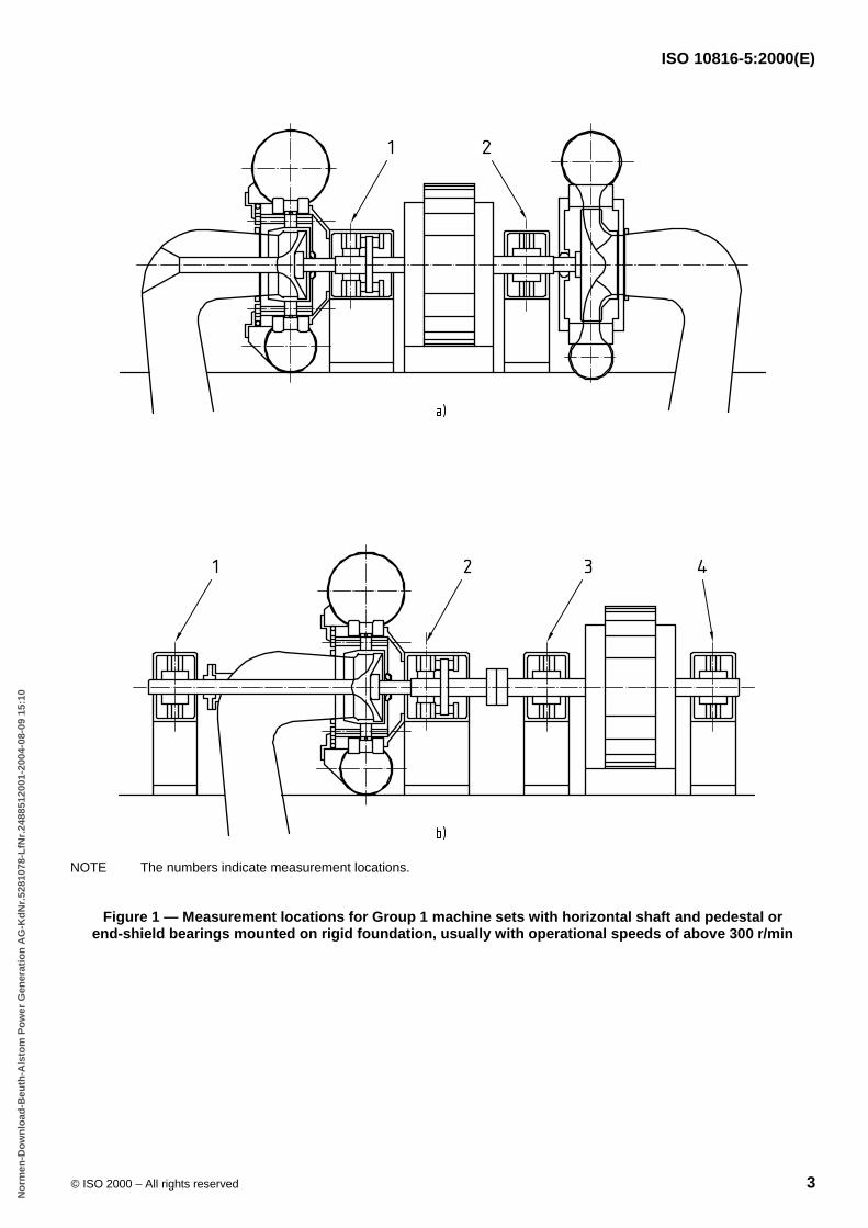
NOTE The numbers indicate measurement locations.
Figure 1 — Measurement locations for Group 1 machine sets with horizontal shaft and pedestal orend-shield bearings mounted on rigid foundation, usually with operational speeds of above 300 r/min
B55EB1B3C7662F79D1B59483A53B9F2F82C98BEEB793928A78C467B382C61E866DE10E2F87F34E8D91B869B14603ECBBAD0B89D103BC2D07EB7876E5628240DE1A26F7E8117640E54B2D000E0CA0206AF0BD6437BCB1BF9FF7746AD35C9469
No
rmen
-Do
wn
load
-Beu
th-A
lsto
m P
ow
er G
ener
atio
n A
G-K
dN
r.52
8107
8-L
fNr.
2488
5120
01-2
004-
08-0
9 15
:10
ISO 10816-5:2000(E)
4 © ISO 2000 – All rights reserved
NOTE The numbers indicate measurement locations.
Figure 2 — Measurement locations for a Group 2 machine set with horizontal shaft and bearing housingswhich are only braced against the casing of the hydraulic machine, usually with operational speeds of
less than 300 r/min
B55EB1B3C7662F79D1B59483A53B9F2F82C98BEEB793928A78C467B382C61E866DE10E2F87F34E8D91B869B14603ECBBAD0B89D103BC2D07EB7876E5628240DE1A26F7E8117640E54B2D000E0CA0206AF0BD6437BCB1BF9FF7746AD35C9469
No
rmen
-Do
wn
load
-Beu
th-A
lsto
m P
ow
er G
ener
atio
n A
G-K
dN
r.52
8107
8-L
fNr.
2488
5120
01-2
004-
08-0
9 15
:10
ISO 10816-5:2000(E)
© ISO 2000 – All rights reserved 5
NOTE The numbers indicate measurement locations.
Figure 3 — Measurement locations for a Group 3 machine set with vertical shaft and bearing housingswhich are all braced against the foundation, usually with operational speeds of between 60 r/min and
1 800 r/min
B55EB1B3C7662F79D1B59483A53B9F2F82C98BEEB793928A78C467B382C61E866DE10E2F87F34E8D91B869B14603ECBBAD0B89D103BC2D07EB7876E5628240DE1A26F7E8117640E54B2D000E0CA0206AF0BD6437BCB1BF9FF7746AD35C9469
No
rmen
-Do
wn
load
-Beu
th-A
lsto
m P
ow
er G
ener
atio
n A
G-K
dN
r.52
8107
8-L
fNr.
2488
5120
01-2
004-
08-0
9 15
:10
ISO 10816-5:2000(E)
6 © ISO 2000 – All rights reserved
NOTE 1 The numbers indicate measurement locations.
NOTE 2 Umbrella-type machines belong to this group.
Figure 4 — Measurement locations for a Group 4 machine set with vertical shaft, lower bearing housingsbraced against the foundation and upper bearing housing braced against the generator stator only, usually
with operational speeds of between 60 r/min and 1 000 r/min
B55EB1B3C7662F79D1B59483A53B9F2F82C98BEEB793928A78C467B382C61E866DE10E2F87F34E8D91B869B14603ECBBAD0B89D103BC2D07EB7876E5628240DE1A26F7E8117640E54B2D000E0CA0206AF0BD6437BCB1BF9FF7746AD35C9469
No
rmen
-Do
wn
load
-Beu
th-A
lsto
m P
ow
er G
ener
atio
n A
G-K
dN
r.52
8107
8-L
fNr.
2488
5120
01-2
004-
08-0
9 15
:10
ISO 10816-5:2000(E)
© ISO 2000 – All rights reserved 7
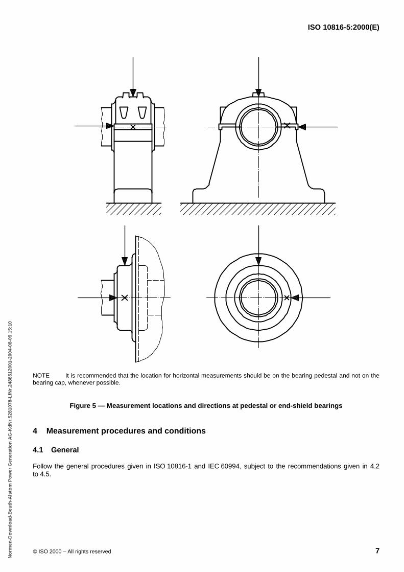
NOTE It is recommended that the location for horizontal measurements should be on the bearing pedestal and not on thebearing cap, whenever possible.
Figure 5 — Measurement locations and directions at pedestal or end-shield bearings
4 Measurement procedures and conditions
4.1 General
Follow the general procedures given in ISO 10816-1 and IEC 60994, subject to the recommendations given in 4.2to 4.5.
B55EB1B3C7662F79D1B59483A53B9F2F82C98BEEB793928A78C467B382C61E866DE10E2F87F34E8D91B869B14603ECBBAD0B89D103BC2D07EB7876E5628240DE1A26F7E8117640E54B2D000E0CA0206AF0BD6437BCB1BF9FF7746AD35C9469
No
rmen
-Do
wn
load
-Beu
th-A
lsto
m P
ow
er G
ener
atio
n A
G-K
dN
r.52
8107
8-L
fNr.
2488
5120
01-2
004-
08-0
9 15
:10
ISO 10816-5:2000(E)
8 © ISO 2000 – All rights reserved
4.2 Measurement type
Absolute bearing housing vibration measurements are commonly made on hydraulic machine sets using seismictransducers measuring the vibration velocity vrms in millimetres per second or, after electronic integration, the vibrationdisplacement sp–p in micrometres. The vibration displacement sp–p can also be measured directly as a relativequantity using displacement transducers in the case where a rigid non-vibrating support can be found.
Because of the special nature of the vibratory behaviour of hydraulic machines and their different speed ranges, thesequantities have favoured ranges of application as follows:
a) For low-speed machines (below 300 r/min), the preferred measurement quantity is the vibration displacementsp–p. If the spectrum is expected to contain high-frequency components, the evaluation should normally bebased on broad-band measurements of both displacement and velocity.
b) For medium- and high-speed machines (300 r/min to 1 800 r/min), the preferred measurement quantity is thevibration velocity vrms. If the spectrum is expected to contain low-frequency components, the evaluation shouldnormally be based on broad-band measurements of both velocity and displacement.
4.3 Measurement locations and directions
Measurement tasks A and B (see clause 1) require measurements to be taken on exposed parts of the machine thatare normally accessible and are representative locations for the so-called force flow in the supporting structure, forexample on all main bearings of the machine set. Typical examples of measurement locations for hydraulic machinesare shown in Figures 1 to 5.
Care shall be taken in this context to ensure that measurements reasonably represent the vibration of the bearinghousings and do not include any local resonance or amplification. The locations and directions for vibrationmeasurements shall be such that they provide adequate sensitivity to the dynamic forces of the machine undervarious operating conditions. Typically, this will often require two orthogonal radial measurement directions on eachbearing cap, pedestal or housing. For low-speed machines with a horizontal shaft axis, such as bulb-turbines asshown in Figure 2, the measurement locations and directions shall be determined with great care.
CAUTION: The vibration measured at the lower guide bearings of vertical machines may sometimes bemisinterpreted; the vibration level measured at such bearings and their surrounding supports which are rigidlyembedded in the buildings is sometimes produced by hydraulic forces, directly transmitted from the hydraulicmachine via the foundation. Such vibrations do not necessarily give a correct image of the vibration of the rotatingshaft system.
For horizontal machines when using portable measuring instrumentation, take measurements in the vertical andhorizontal directions 90� apart (perpendicular to the shaft axis) and, if possible, in the axial direction (parallel to theshaft axis) as shown in Figure 5.
A single transducer may be used on a bearing cap or pedestal in place of the more typical pair of orthogonaltransducers if it is known to provide adequate information about the magnitude of the machine vibration. However,caution should be observed in evaluating vibration from a single transducer at a measurement location, because itmay not be oriented to provide a reasonable approximation to the maximum value at that location.
In the case of vertical or inclined machine sets, the locations and directions that give maximum vibration readingsshall be used, for example the stiff and the elastic axis (this is important for cases with spider arm supportconstructions), and the specific location and direction shall be recorded with the measurement. If possible, the settingof the transducers at different bearings should be in line. For vertical machines, the preferred measurement directionsare upstream and 90� to that.
For monitoring purposes (task A) only, in some cases measurement locations may be reduced to the most importantones, mainly at machine sets with four or more bearings. The selection should be based on vibration performanceanalyses, simulating all types of faults or disturbing effects. Preferred measuring locations should be those wherepossible disturbing events produce significant bearing housing amplitudes (velocity or displacement).
B55EB1B3C7662F79D1B59483A53B9F2F82C98BEEB793928A78C467B382C61E866DE10E2F87F34E8D91B869B14603ECBBAD0B89D103BC2D07EB7876E5628240DE1A26F7E8117640E54B2D000E0CA0206AF0BD6437BCB1BF9FF7746AD35C9469
No
rmen
-Do
wn
load
-Beu
th-A
lsto
m P
ow
er G
ener
atio
n A
G-K
dN
r.52
8107
8-L
fNr.
2488
5120
01-2
004-
08-0
9 15
:10
ISO 10816-5:2000(E)
© ISO 2000 – All rights reserved 9
The installation of one single transducer at the bearing pedestal or housing in horizontal or slightly inclined position iscommonly considered adequate for continuous monitoring of Group 1 or 2 machine sets. For monitoring axialvibration of the machine, one transducer mounted on the thrust bearing is often sufficient.
4.4 Measurement equipment
The measurement equipment shall be capable of broad-band measurement of vibration with flat response within thefollowing frequency ranges:
� from at least a quarter of the nominal rotational frequency up to the product of three times the rotationalfrequency times the number of buckets or blades, if the measurement quantity is the vibration displacementsp-p;
� from 2 Hz to 1 000 Hz if the measurement quantity is the vibration velocity vrms.
NOTE If the measurement equipment is also to be used for diagnostic purposes, an upper frequency limit higher than thatspecified may be necessary (e.g. higher than 1 000 Hz in the case of vibration velocity measurements).
Vibration displacement can be measured as an absolute quantity with special seismic transducers or accelerometers.If standard equipment is applied, particular attention should be taken to ensure that the measuring instrumentation isfitted with specific electronic compensation to obtain a flat response over the specified frequency range.
For machines with nominal speeds lower than or equal to 300 r/min, vibration displacement is often measured asrelative quantity (relative to the foundation) using contact or non-contact displacement transducers. Thesetransducers shall be installed on rigid bars or frames fixed to rigid parts of the foundation. It is necessary to ensurethat the natural frequencies of these elements are at least higher than ten times the nominal rotational frequency, andalso they should not be a multiple of this frequency.
Vibration velocity shall be measured as an absolute quantity with seismic transducers or accelerometers. If seismictransducers are used, attention should be taken to ensure that the measuring instrumentation is fitted with specificelectronic compensation to obtain a flat response over the total frequency range from 2 Hz to 1 000 Hz.
Transducers for absolute vibration measurements shall be mounted on rigid parts of the bearing housing or adjacentsurrounding structures which can be classified to give a representative vibration response of the machine. Particularattention shall be given to ensure that transducer mounting complies with specifications from the transducermanufacturer. If additional elements for mounting such transducers are necessary, it shall be ensured that the naturalfrequencies of those elements are at least higher than ten times the nominal rotational frequency, and also theyshould not be a multiple of this frequency.
The characteristics of the measuring system shall be known with regard to the effects of the environment, includingthe following:
� temperature variations;
� magnetic fields;
� sound fields;
� power source variation;
� transducer cable length;
� transducer orientation.
Particular attention shall be given to ensuring that the vibration sensing transducers are correctly mounted and do notaffect the vibration response characteristics of the machine.
B55EB1B3C7662F79D1B59483A53B9F2F82C98BEEB793928A78C467B382C61E866DE10E2F87F34E8D91B869B14603ECBBAD0B89D103BC2D07EB7876E5628240DE1A26F7E8117640E54B2D000E0CA0206AF0BD6437BCB1BF9FF7746AD35C9469
No
rmen
-Do
wn
load
-Beu
th-A
lsto
m P
ow
er G
ener
atio
n A
G-K
dN
r.52
8107
8-L
fNr.
2488
5120
01-2
004-
08-0
9 15
:10
ISO 10816-5:2000(E)
10 © ISO 2000 – All rights reserved
4.5 Operational conditions
Measurements shall be carried out when the rotor and the main bearings have reached their normal steady-stateoperating temperatures and with the machine running under steady-state conditions.
5 Evaluation
5.1 General
ISO 10816-1 provides a general description of the two evaluation criteria used to assess vibration severity on variousclasses of machines. One criterion considers the magnitude of vibration observed by broad-band measurement; thesecond considers changes in magnitude, irrespective of whether they are increases or decreases.
5.2 Criterion I: Vibration magnitude
The reliable and safe running of a machine under normal operating conditions requires that the vibration magnitudeshould remain below certain limits consistent with, for example, acceptable kinetic loads and acceptable vibrationtransmission into the support structure and foundation. Generally, this criterion will be taken as the basis for theevaluation of machines in the absence of any other established knowledge of the satisfactory running characteristicsfor machines of that type (e.g. for new machine types).
The maximum vibration magnitude observed at each bearing pedestal or housing is assessed against the evaluationzones defined below.
Zone A : The vibration of newly commissioned machines would normally fall within this zone.
Zone B : Machines with vibration within this zone are normally considered acceptable for unrestricted long-termoperation.
Zone C : Machines with vibration within this zone are normally considered unsatisfactory for long-term continuousoperation. Generally, the machine may be operated for a limited period in this condition until a suitable opportunityarises for remedial action.
Zone D : Vibration values within this zone are normally considered to be of sufficient severity to cause damage to themachine.
Numerical values assigned to the zone boundaries are not intended to serve as acceptance specification, which shallbe subject to agreement between the machine manufacturer and the customer. However, the zone boundariesprovide guidelines for ensuring that gross deficiencies or unrealistic requirements are avoided. In certain cases, theremay be specific features associated with a particular machine which would require different zone boundary values(higher or lower) to be used. In such cases, it is normally the responsibility of the machine manufacturer to explain thereason for this and, in particular, to confirm that the machine would not be endangered by operating with highervibration values.
NOTE Vibration magnitudes for recommissioned units with increased output, usually characterized as "uprated", may be locatedin zone A or B. The choice of zone A or B depends, however, on the relation between the new excitation forces and the capacity ofthe new and re-used components to withstand long-term dynamic exposure.
5.3 Evaluation zone limits
5.3.1 Turbine operating conditions
Recommended values for the zone boundaries are given in Tables A.1 to A.4 for the four machine groups covered bythis part of ISO 10816. Application of these criteria is valid for measurements in a radial direction on bearing pedestalsor housings of machine sets with nominal speeds between 60 r/min and 1 800 r/min operating within the contractuallypermissible steady-state range, as well as at other load conditions if the machine has been made suitable for theseparticular conditions. Higher values of vibration may be permitted under the conditions specified in annex B.
B55EB1B3C7662F79D1B59483A53B9F2F82C98BEEB793928A78C467B382C61E866DE10E2F87F34E8D91B869B14603ECBBAD0B89D103BC2D07EB7876E5628240DE1A26F7E8117640E54B2D000E0CA0206AF0BD6437BCB1BF9FF7746AD35C9469
No
rmen
-Do
wn
load
-Beu
th-A
lsto
m P
ow
er G
ener
atio
n A
G-K
dN
r.52
8107
8-L
fNr.
2488
5120
01-2
004-
08-0
9 15
:10
ISO 10816-5:2000(E)
© ISO 2000 – All rights reserved 11
Zone boundary values are specified for both measurement quantities. If both quantities, vibration velocity anddisplacement, are measured and compared to the corresponding values in Tables A.1, A.3 and A.4, the evaluationwhich is most restrictive shall apply.
The limiting values are applicable for all types of machine sets belonging to one group, independent of head andpower, except for the restrictions given in clause 1. For hydrodynamically smoother running machines, normally lowerbearing housing vibration may be expected.
In the case of pump-turbines, increased bearing housing vibration amplitudes may occur because of the runnerdesign criteria, which are a compromise between the optimal design for a turbine and a pump runner.
The values in Tables A.1 to A.4 are based on statistical analyses of collected measurement data from more than1 400 samples, collected worldwide from machine sets with different powers and speeds within all four groups. A briefdescription of the analysis procedure and the applied regression technique is given in annex C.
NOTE 1 In general, an overall judgement of the vibratory state of the machine is made on the basis of both the bearing housingvibration as defined above and the measurements performed on the shaft (see ISO 7919-5).
NOTE 2 As explained in annex C, the given limiting values are based on a statistical procedure and the defining of predictivelimits; this was necessary due to the wide spread of the measured data. Therefore it should not be assumed that a correctcorrelation between zone boundaries and possible faults or troubles at the observed machine will exist in all cases.
5.3.2 Pump operating conditions
At present, sufficient data are not available to prepare criteria for machine sets in pump operating conditions. They willbe incorporated in a future edition of this part of ISO 10816 when available.
5.3.3 Special operating conditions
Attention should be paid to the following operating conditions:
� steady-state operating conditions at low partial load, at overload, and the frequent transient operatingconditions during start-up and shut-down;
� rare transient operating conditions such as emergency shut-down, no-discharge operation, and runningthrough the brake quadrant with pumps and pump-turbines.
The evaluation of such processes is much more difficult than that of operation in the specified load range. At presentthere are insufficient data and experience available to establish limiting curves for these operating conditions. Theless the operating condition corresponds to the nominal conditions, the more the flow within the hydraulic machine isdisturbed; disturbances such as separation and swirl generate violent stochastic excitation. Due to the density ofwater, the forces caused by the stochastic excitation are much greater than in thermal turbo machines. Thereforeduring operation outside the specified load range, the bearing or structure vibrations caused by mass unbalance are,as a rule, totally masked by the stochastic components. Because of these large stochastic components under extra-ordinary operating conditions, less reliance should be given to the instantaneous value and more to the mean valueover a representative measurement period.
5.3.4 Axial vibration
It is not common practice to measure axial vibration on main radial load-carrying bearings during continuousoperational monitoring. Such measurements are primarily used during periodic vibration surveys or for diagnosticpurposes. At thrust bearings, axial vibration in general correlates with axial pulsations which could cause damage tothe axial load-carrying surfaces. Criteria for axial vibration of bearings cannot be given at present because of the lackof measured data.
B55EB1B3C7662F79D1B59483A53B9F2F82C98BEEB793928A78C467B382C61E866DE10E2F87F34E8D91B869B14603ECBBAD0B89D103BC2D07EB7876E5628240DE1A26F7E8117640E54B2D000E0CA0206AF0BD6437BCB1BF9FF7746AD35C9469
No
rmen
-Do
wn
load
-Beu
th-A
lsto
m P
ow
er G
ener
atio
n A
G-K
dN
r.52
8107
8-L
fNr.
2488
5120
01-2
004-
08-0
9 15
:10
ISO 10816-5:2000(E)
12 © ISO 2000 – All rights reserved
5.4 Criterion II: Change in vibration magnitude
This criterion provides an assessment of a change in vibration magnitude from a previously established referencevalue when operating under steady-state conditions. A significant change in broad-band vibration magnitude mayoccur which requires some action even though the alarm zone C of Criterion I has not been reached. Such changescan be instantaneous or progressive with time and may indicate that damage has occurred or be a warning of animpending failure or some other irregularity. Criterion II is specified on the basis of change in broad-band vibrationmagnitude occurring under steady operating conditions. Steady operating conditions should be interpreted to includesmall changes in the machine power or operational conditions.
When Criterion II is applied, the vibration measurements being compared shall be taken at the same transducerlocation and orientation, and under approximately the same machine operating conditions. Obvious changes in thenormal vibration magnitudes, regardless of their total amount, should be investigated, because a dangerous situationcould then be avoided. When changes in vibration magnitude exceed 25 % of the upper boundary value of zone B(defined as B/C in Tables A.1 to A.4), such changes should be considered significant, particularly if they are sudden.Diagnostic investigations should be initiated to ascertain the reason for the change and to determine what furtheractions are appropriate.
NOTE The 25 % value is considered significant regardless of whether it is an increase or decrease in vibration. The 25 % value isprovided as a guideline, but other values may be used based on experience with a specific machine.
5.5 Operational limits
5.5.1 General
For long-term operation, it is common practice to establish operational vibration limits. These limits take the form ofALARMS and TRIPS.
ALARMS : To provide a warning that a defined value of vibration has been reached or a significant change hasoccurred, at which remedial action may be necessary. In general, if an ALARM situation occurs, operation cancontinue for a period whilst investigations are carried out to identify the reason for the change in vibration and defineany remedial action.
TRIPS: To specify the magnitude of vibration beyond which further operation of the machine may cause damage. Ifthe TRIP value is exceeded, immediate action should be taken to reduce the vibration or the machine should be shutdown.
Different operational limits, reflecting differences in dynamic loading and support stiffness, may be specified fordifferent measurement positions and directions.
5.5.2 Setting of ALARMS
The ALARM values may vary considerably, up or down, for different machines. The values chosen will normally beset relative to a baseline value determined from experience for the measurement position or direction for thatparticular machine.
It is recommended that the ALARM value should be set higher than the baseline by an amount equal to 25 % of theupper limit of zone B. If the baseline is low, the ALARM may be below zone C.
Where there is no established baseline (for example with a new machine) the initial ALARM setting should be basedeither on experience with other similar machines or relative to agreed acceptance values. After a period of time, thesteady-state baseline value will be established and the ALARM setting should be adjusted accordingly.
In either case it is recommended that the ALARM value should not normally exceed 1,25 times the upper limit ofzone B (this limit is defined as B/C in Tables A.1 to A.4).
B55EB1B3C7662F79D1B59483A53B9F2F82C98BEEB793928A78C467B382C61E866DE10E2F87F34E8D91B869B14603ECBBAD0B89D103BC2D07EB7876E5628240DE1A26F7E8117640E54B2D000E0CA0206AF0BD6437BCB1BF9FF7746AD35C9469
No
rmen
-Do
wn
load
-Beu
th-A
lsto
m P
ow
er G
ener
atio
n A
G-K
dN
r.52
8107
8-L
fNr.
2488
5120
01-2
004-
08-0
9 15
:10
ISO 10816-5:2000(E)
© ISO 2000 – All rights reserved 13
If the steady-state baseline changes (for example after a machine overhaul), the ALARM setting should be revisedaccordingly. Different ALARM settings, reflecting differences in dynamic loading and support stiffness, may exist fordifferent measurement locations and directions.
5.5.3 Setting of TRIPS
The TRIP values will generally relate to the mechanical integrity of the machine and be dependent on any specificdesign features which have been introduced to enable the machine to withstand abnormal dynamic forces. Thevalues used will, therefore, generally be the same for all machines of similar design and would not normally be relatedto the steady-state baseline value used for setting ALARMS.
There may, however, be differences for machines of different design and it is not possible to give clear guidelines forabsolute TRIP values. In general, the TRIP value will be within zone C or D, but it is recommended that the TRIPvalue should not exceed 1,25 times the upper limit of zone C (this limit is defined as C/D in Tables A.1 to A.4).
5.5.4 Special operating conditions
When the machine is operating outside the normal load range and during all transient operating conditions, ALARMand possibly TRIP contacts shall be blocked for these conditions. If the machine should be monitored during theseoperating conditions too, a second set of ALARM and TRIP values shall be selected according to the maximumvibration values accepted during commissioning of the machine.
5.6 Supplementary procedures/criteria
The measurement and evaluation of machine vibration given in this part of ISO 10816 may be supplemented by shaftvibration measurements and the applicable criteria given in ISO 7919-5. It is important to recognize that there is nosimple way to relate bearing housing vibration to shaft vibration, or vice versa. Thus, when the criteria of this part ofISO 10816 and those of ISO 7919-5 are both applied in vibration-severity assessment, independent shaft and bearingpedestal or housing vibration measurement shall be made. If application of the different criteria leads to differentassessments of the machine vibration severity, the more restrictive zone classification is considered to apply.
5.7 Evaluation based on vibration vector information
The evaluation considered in this part of ISO 10816 is limited to broad-band vibration without reference to frequencycomponents or phase. This will, in most cases, be adequate for acceptance testing and operational monitoringpurposes. However, for long-term condition monitoring purposes and for diagnostics, the use of vibration vectorinformation is particularly useful for detecting and defining changes in the dynamic state of the machine. In somecases, these changes would go undetected when using only broad-band vibration measurements (see, for example,ISO 10816-1). The specification of criteria for this, however, is beyond the scope of this part of ISO 10816.
B55EB1B3C7662F79D1B59483A53B9F2F82C98BEEB793928A78C467B382C61E866DE10E2F87F34E8D91B869B14603ECBBAD0B89D103BC2D07EB7876E5628240DE1A26F7E8117640E54B2D000E0CA0206AF0BD6437BCB1BF9FF7746AD35C9469
No
rmen
-Do
wn
load
-Beu
th-A
lsto
m P
ow
er G
ener
atio
n A
G-K
dN
r.52
8107
8-L
fNr.
2488
5120
01-2
004-
08-0
9 15
:10
ISO 10816-5:2000(E)
14 © ISO 2000 – All rights reserved
Annex A(normative)
Evaluation zone boundaries
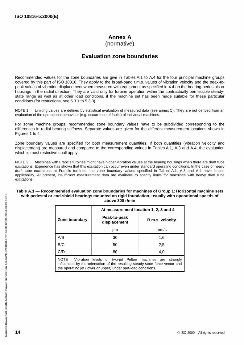
Recommended values for the zone boundaries are give in Tables A.1 to A.4 for the four principal machine groupscovered by this part of ISO 10816. They apply to the broad-band r.m.s. values of vibration velocity and the peak-to-peak values of vibration displacement when measured with equipment as specified in 4.4 on the bearing pedestals orhousings in the radial direction. They are valid only for turbine operation within the contractually permissible steady-state range as well as at other load conditions, if the machine set has been made suitable for these particularconditions (for restrictions, see 5.3.1 to 5.3.3).
NOTE 1 Limiting values are defined by statistical evaluation of measured data (see annex C). They are not derived from anevaluation of the operational behaviour (e.g. occurrence of faults) of individual machines.
For some machine groups, recommended zone boundary values have to be subdivided corresponding to thedifferences in radial bearing stiffness. Separate values are given for the different measurement locations shown inFigures 1 to 4.
Zone boundary values are specified for both measurement quantities. If both quantities (vibration velocity anddisplacement) are measured and compared to the corresponding values in Tables A.1, A.3 and A.4, the evaluationwhich is most restrictive shall apply.
NOTE 2 Machines with Francis turbines might have higher vibration values at the bearing housings when there are draft tubeexcitations. Experience has shown that this excitation can occur even under standard operating conditions. In the case of heavydraft tube excitations at Francis turbines, the zone boundary values specified in Tables A.1, A.3 and A.4 have limitedapplicability. At present, insufficient measurement data are available to specify limits for machines with heavy draft tubeexcitations.
Table A.1 — Recommended evaluation zone boundaries for machines of Group 1 : Horizontal machine setswith pedestal or end-shield bearings mounted on rigid foundation, usually with operational speeds of
above 300 r/min
At measurement location 1, 2, 3 and 4
Zone boundary Peak-to-peakdisplacement
�m
R.m.s. velocity
mm/s
A/B 30 1,6
B/C 50 2,5
C/D 80 4,0
NOTE Vibration levels of two-jet Pelton machines are stronglyinfluenced by the orientation of the resulting steady-state force vector andthe operating jet (lower or upper) under part-load conditions.
B55EB1B3C7662F79D1B59483A53B9F2F82C98BEEB793928A78C467B382C61E866DE10E2F87F34E8D91B869B14603ECBBAD0B89D103BC2D07EB7876E5628240DE1A26F7E8117640E54B2D000E0CA0206AF0BD6437BCB1BF9FF7746AD35C9469
No
rmen
-Do
wn
load
-Beu
th-A
lsto
m P
ow
er G
ener
atio
n A
G-K
dN
r.52
8107
8-L
fNr.
2488
5120
01-2
004-
08-0
9 15
:10
ISO 10816-5:2000(E)
© ISO 2000 – All rights reserved 15
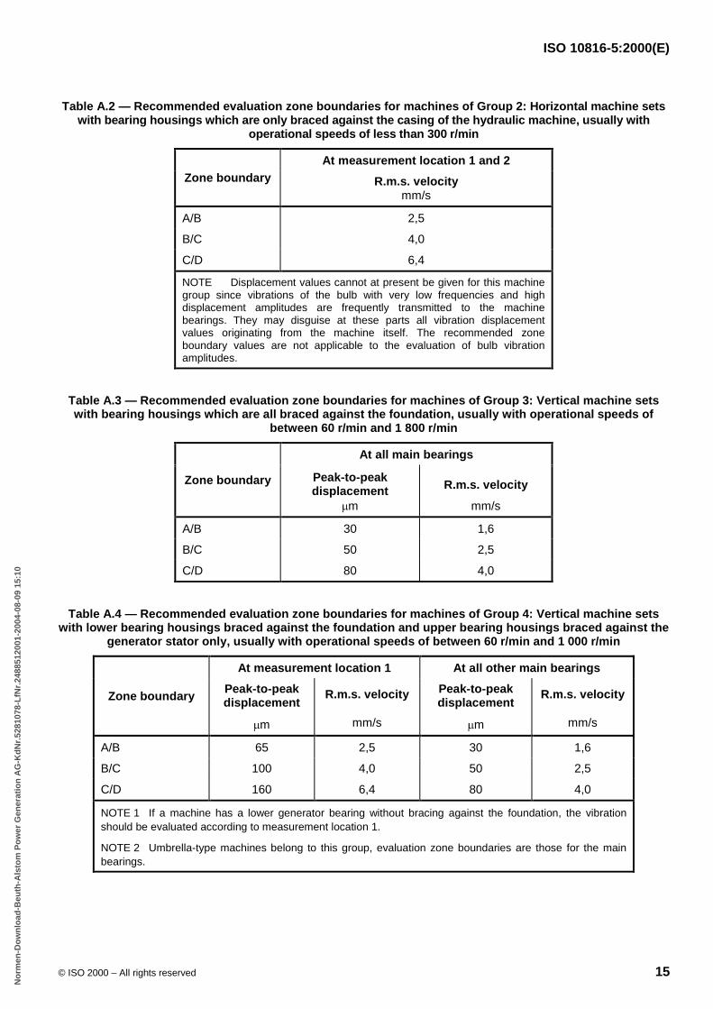
Table A.2 — Recommended evaluation zone boundaries for machines of Group 2: Horizontal machine setswith bearing housings which are only braced against the casing of the hydraulic machine, usually with
operational speeds of less than 300 r/min
At measurement location 1 and 2Zone boundary R.m.s. velocity
mm/s
A/B 2,5
B/C 4,0
C/D 6,4
NOTE Displacement values cannot at present be given for this machinegroup since vibrations of the bulb with very low frequencies and highdisplacement amplitudes are frequently transmitted to the machinebearings. They may disguise at these parts all vibration displacementvalues originating from the machine itself. The recommended zoneboundary values are not applicable to the evaluation of bulb vibrationamplitudes.
Table A.3 — Recommended evaluation zone boundaries for machines of Group 3: Vertical machine setswith bearing housings which are all braced against the foundation, usually with operational speeds of
between 60 r/min and 1 800 r/min
At all main bearings
Zone boundary Peak-to-peakdisplacement
�m
R.m.s. velocity
mm/s
A/B 30 1,6
B/C 50 2,5
C/D 80 4,0
Table A.4 — Recommended evaluation zone boundaries for machines of Group 4: Vertical machine setswith lower bearing housings braced against the foundation and upper bearing housings braced against the
generator stator only, usually with operational speeds of between 60 r/min and 1 000 r/min
At measurement location 1 At all other main bearings
Zone boundaryPeak-to-peakdisplacement
�m
R.m.s. velocity
mm/s
Peak-to-peakdisplacement
�m
R.m.s. velocity
mm/s
A/B 65 2,5 30 1,6
B/C 100 4,0 50 2,5
C/D 160 6,4 80 4,0
NOTE 1 If a machine has a lower generator bearing without bracing against the foundation, the vibrationshould be evaluated according to measurement location 1.
NOTE 2 Umbrella-type machines belong to this group, evaluation zone boundaries are those for the mainbearings.
B55EB1B3C7662F79D1B59483A53B9F2F82C98BEEB793928A78C467B382C61E866DE10E2F87F34E8D91B869B14603ECBBAD0B89D103BC2D07EB7876E5628240DE1A26F7E8117640E54B2D000E0CA0206AF0BD6437BCB1BF9FF7746AD35C9469
No
rmen
-Do
wn
load
-Beu
th-A
lsto
m P
ow
er G
ener
atio
n A
G-K
dN
r.52
8107
8-L
fNr.
2488
5120
01-2
004-
08-0
9 15
:10
ISO 10816-5:2000(E)
16 © ISO 2000 – All rights reserved
Annex B(informative)
Special features of bearing housing vibration of hydraulic machine sets
B.1 General
The principles of the mechanics of bearing housing vibration are explained in ISO 10816-1. They are based mainly ona broad spectrum of theoretical and experimental investigations on horizontal shaft machines. Until now, not as muchattention has been paid to machines with vertical shafts which are more common for hydraulic machine sets.
For hydraulic machines, bearing housing vibration may occur over a wide range of frequencies. Possible causes ofvibration are given in B.2 to B.4.
B.2 Mechanical causes
These are incorrect shaft alignment, bearing anisotropy, loose assemblies in rotating or stationary parts, and residualunbalance in the runner or impeller, the generator or the exciter rotor.
Frequencies to be expected are the frequency of rotation and its harmonics.
B.3 Electrical causes
These are inadequately equalized magnetic pull in the rotor of the coupled electrical machines.
Frequencies to be expected are the frequency of rotation and its harmonics.
B.4 Hydraulic causes
B.4.1 Flow through the waterways
Frequencies to be expected are the frequency of rotation, frequency of the blade or bucket passing, or variouscombinations of these.
B.4.2 Draft tube flow instabilities
These occur in Francis turbines even during steady-state operation outside the optimum efficiency range.
Frequencies to be expected are those below the frequency of rotation, often down to one-third to one-quarter of it.Resonance with hydraulic structures or with the grid might occur, aggravating the phenomenon.
B.4.3 Cavitation
This is due to incorrect flow conditions around the runner or impeller blade profiles, and occurs mostly within thehigher load ranges. Another important reason for cavitation is a change in tail water level.
Frequencies to be expected are usually high ones, as for bursts.
B55EB1B3C7662F79D1B59483A53B9F2F82C98BEEB793928A78C467B382C61E866DE10E2F87F34E8D91B869B14603ECBBAD0B89D103BC2D07EB7876E5628240DE1A26F7E8117640E54B2D000E0CA0206AF0BD6437BCB1BF9FF7746AD35C9469
No
rmen
-Do
wn
load
-Beu
th-A
lsto
m P
ow
er G
ener
atio
n A
G-K
dN
r.52
8107
8-L
fNr.
2488
5120
01-2
004-
08-0
9 15
:10
ISO 10816-5:2000(E)
© ISO 2000 – All rights reserved 17
B.4.4 Hydroelastic vibration
This can be due to incorrectly shaped discharge edges of hydraulic profiles (blades, buckets, stayvanes, etc.).
Frequencies to be expected are from below 100 Hz to several kilohertz (depending on profile dimensions and flowvelocities). Often a pronounced beat character is observed.
B.4.5 Self-excited vibrations
These occur where the movement of mechanical parts (seals, clearances) influences the flow around or throughthem.
Frequencies to be expected are those slightly above the frequency of rotation, often coinciding with the bendingnatural frequencies of the rotating system.
In machines of type Group 3 and 4 at part-load or overload, higher vibration may occur due to hydraulic vortices.Provided that such machine conditions with restricted operational periods do not effect fatigue of main structuralmembers (even with higher vibration levels but lying below the recommended limiting zones), the machine set may bemade suitable also for these particular operating conditions.
B.5 Additional excitations
During regular transient operating conditions such as start-up and shut-down, additional excitation forces interact withthe runner, inducing a wider spectrum and higher amplitudes. During load rejections, even Kaplan turbines can besubjected to draft tube instabilities (see B.4.2) with considerable subsynchronous bearing vibration amplitudes. Undersimilar conditions (especially for rotor arrangements with only two radial bearings) resonance phenomena can beobserved at certain speeds while decelerating, with bearing vibration amplitudes containing one or more of the rotor'snatural frequencies corresponding to the instantaneous speed.
At frequent transient operating conditions, such as start-up and shut-down, random excitations with broad-bandspectra are dominant. In the case of extreme transients, occurring for example at a failure of a shut-off valve, theintensity of this broad-band excitation spectrum increases even more.
In contrast to thermal machines, hydraulic machines can normally be started-up and shut-down or power can bechanged rapidly and frequently. Hydraulic machines are therefore often used for peak-load supply or for frequencyand power control. Since such operations also involve frequent starts and stops, and often rapid changeover from oneoperational state to the other, these machines are exposed to enhanced vibration and stress. For peak-load or pump-storage equipment, transient operating conditions can become so frequent that the sum of the time intervals ofincreased vibration amounts to more than 1 ‰ of the overall operating time. These frequent transient operatingconditions should then be evaluated separately with respect to the additional stress and fatigue on the bearings andother involved parts of the machine.
B55EB1B3C7662F79D1B59483A53B9F2F82C98BEEB793928A78C467B382C61E866DE10E2F87F34E8D91B869B14603ECBBAD0B89D103BC2D07EB7876E5628240DE1A26F7E8117640E54B2D000E0CA0206AF0BD6437BCB1BF9FF7746AD35C9469
No
rmen
-Do
wn
load
-Beu
th-A
lsto
m P
ow
er G
ener
atio
n A
G-K
dN
r.52
8107
8-L
fNr.
2488
5120
01-2
004-
08-0
9 15
:10
ISO 10816-5:2000(E)
18 © ISO 2000 – All rights reserved
Annex C(informative)
Analysis procedure and applied regression technique
Using data (measured quantities on bearing housings or pedestals) collected from 11 countries, two databaseswere established (data from different machine types with vertical or horizontal shaft orientation and differentspeeds). The databases were structured as follows:
� measured bearing housing displacement sp–p versus rotational speed of the machine;
� measured bearing housing velocity vrms versus rotational speed of the machine.
On some of the submitted rough data, modifications were necessary because of incompatibility. With the improveddata sets the following steps in the described procedure (using a software package for statistical analysis) wereperformed (see reference [5]):
a) proof of data distribution within the specified speed range;
b) regression analysis using a "Multiplicative model" Y = aXb with transformed data in a log-log scaled databasewith the dependent variable displacement or velocity and the independent variable rotational speed;
c) computation and plot of
� analysis of variance,
� lack of fit and pure error test,
� mean value regression curve with a defined 98 % probability limit and prediction limits (between 60 % and95 % in steps of 5 %),
� residuals,
� normal plot of cumulative residuals,
� F-test (for significance of regression model);
d) linearization of computed prediction curves (mainly near the boundaries, in the low- and high-speed range) in adouble logarithmic scale;
e) definition of the prediction limit curve 85 % as zone boundary B/C, which implies that 92,5 % of all collectedmeasurement data are below this evaluated prediction curve;
f) the ratios between the zone boundaries A/B, B/C and C/D were found through intensive discussions within theworking group and with experts in other working groups about safety margins and trip or alarm settings.
B55EB1B3C7662F79D1B59483A53B9F2F82C98BEEB793928A78C467B382C61E866DE10E2F87F34E8D91B869B14603ECBBAD0B89D103BC2D07EB7876E5628240DE1A26F7E8117640E54B2D000E0CA0206AF0BD6437BCB1BF9FF7746AD35C9469
No
rmen
-Do
wn
load
-Beu
th-A
lsto
m P
ow
er G
ener
atio
n A
G-K
dN
r.52
8107
8-L
fNr.
2488
5120
01-2
004-
08-0
9 15
:10
ISO 10816-5:2000(E)
© ISO 2000 – All rights reserved 19
Bibliography
[1] ISO 2954, Mechanical vibration of rotating and reciprocating machinery — Requirements for instruments formeasuring vibration severity.
[2] ISO 7919-1, Mechanical vibration of non-reciprocating machines — Measurements on rotating shafts andevaluation criteria — Part 1: General guidelines.
[3] ISO 7919-5, Mechanical vibration of non-reciprocating machines — Measurements on rotating shafts andevaluation criteria — Part 5: Machines sets in hydraulic power generating and pumping plants.
[4] ISO 10816-3, Mechanical vibration — Evaluation of machine vibration by measurements on non-rotatingparts — Part 3: Industrial machines with nominal power above 15 kW and nominal speeds between120 r/min and 15000 r/min when measured in situ.
[5] Schmid; Guetl and Posch. Statistical analyses for the evaluation of limiting curves — Bearing housingvibration. Technical Report, Tiroler Wasserkraftenwerke, Innsbruck, August 1993.
B55EB1B3C7662F79D1B59483A53B9F2F82C98BEEB793928A78C467B382C61E866DE10E2F87F34E8D91B869B14603ECBBAD0B89D103BC2D07EB7876E5628240DE1A26F7E8117640E54B2D000E0CA0206AF0BD6437BCB1BF9FF7746AD35C9469
No
rmen
-Do
wn
load
-Beu
th-A
lsto
m P
ow
er G
ener
atio
n A
G-K
dN
r.52
8107
8-L
fNr.
2488
5120
01-2
004-
08-0
9 15
:10

ISO 10816-5:2000(E)
ICS 17.160; 27.140Price based on 19 pages
© ISO 2000 – All rights reserved
B55EB1B3C7662F79D1B59483A53B9F2F82C98BEEB793928A78C467B382C61E866DE10E2F87F34E8D91B869B14603ECBBAD0B89D103BC2D07EB7876E5628240DE1A26F7E8117640E54B2D000E0CA0206AF0BD6437BCB1BF9FF7746AD35C9469
No
rmen
-Do
wn
load
-Beu
th-A
lsto
m P
ow
er G
ener
atio
n A
G-K
dN
r.52
8107
8-L
fNr.
2488
5120
01-2
004-
08-0
9 15
:10