Introduction of Pneumatics -...
45
Introduction of Pneumatics 유공압설계 및 실습 (25273) Fall 2007
Transcript of Introduction of Pneumatics -...
Introduction of Pneumatics
유공압설계및실습 (25273)Fall 2007
Fluid Power Control & Design Laboratory
2
Contents
1. Introduction2. Fundamentals3. Air generation4. Pneumatic actuators5. Pneumatic valves6. Vacuum technology7. Typical circuit
Fluid Power Control & Design Laboratory
3
Contents
1. Introduction2. Fundamentals3. Air generation4. Pneumatic actuators5. Pneumatic valves6. Vacuum technology7. Typical circuit
Fluid Power Control & Design Laboratory
4
Concept
Pneumatics — use compressed air as a working medium to implement transfer, transition, distribution, and control of energy.Industrial applications:
Automobile manufacture, automatic industry, food industry…General methods of material handling
clamping, shifting, positioning, orienting…General applications
packaging, filling, locking, sorting of parts…Machining and working operations
drilling, turning, milling, sawing…
Fluid Power Control & Design Laboratory
5
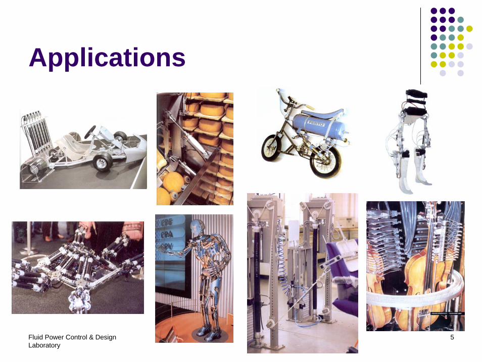
Applications
Fluid Power Control & Design Laboratory
6
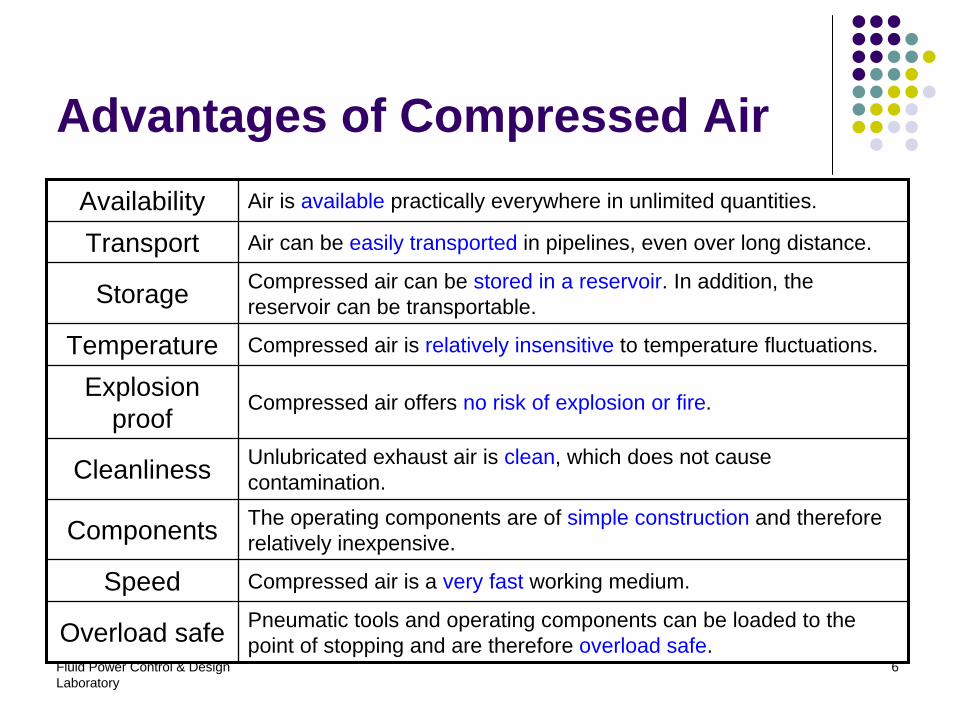
Advantages of Compressed AirAvailability Air is available practically everywhere in unlimited quantities.
Transport Air can be easily transported in pipelines, even over long distance.
Storage Compressed air can be stored in a reservoir. In addition, the reservoir can be transportable.
Temperature Compressed air is relatively insensitive to temperature fluctuations.
Explosion proof
Compressed air offers no risk of explosion or fire.
Cleanliness Unlubricated exhaust air is clean, which does not cause contamination.
Components The operating components are of simple construction and therefore relatively inexpensive.
Speed Compressed air is a very fast working medium.
Overload safe Pneumatic tools and operating components can be loaded to the point of stopping and are therefore overload safe.
Fluid Power Control & Design Laboratory
7
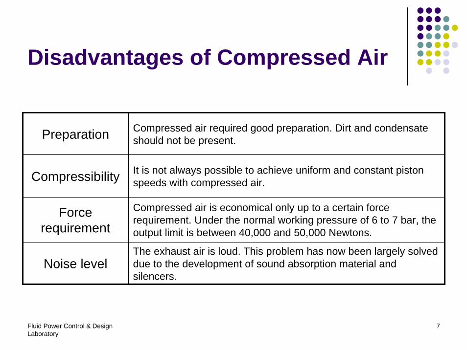
Disadvantages of Compressed Air
Preparation Compressed air required good preparation. Dirt and condensate should not be present.
Compressibility It is not always possible to achieve uniform and constant pistonspeeds with compressed air.
Force requirement
Compressed air is economical only up to a certain force requirement. Under the normal working pressure of 6 to 7 bar, the output limit is between 40,000 and 50,000 Newtons.
Noise levelThe exhaust air is loud. This problem has now been largely solved due to the development of sound absorption material and silencers.
Fluid Power Control & Design Laboratory
8
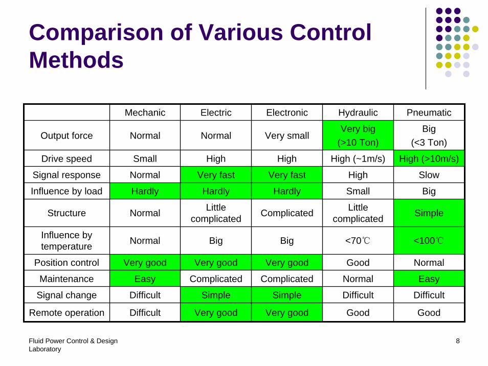
Comparison of Various Control Methods
Mechanic Electric Electronic Hydraulic Pneumatic
Output force Normal Normal Very smallVery big
(>10 Ton)Big
(<3 Ton)
Drive speed Small High High High (~1m/s) High (>10m/s)
Signal response Normal Very fast Very fast High Slow
Influence by load Hardly Hardly Hardly Small Big
Structure Normal Little complicated Complicated Little
complicated Simple
Influence by temperature Normal Big Big <70℃ <100℃
Position control Very good Very good Very good Good Normal
Maintenance Easy Complicated Complicated Normal Easy
Signal change Difficult Simple Simple Difficult Difficult
Remote operation Difficult Very good Very good Good Good
Fluid Power Control & Design Laboratory
9
Contents
1. Introduction2. Fundamentals3. Air generation4. Pneumatic actuators5. Pneumatic valves6. Vacuum technology7. Typical circuit
Fluid Power Control & Design Laboratory
10
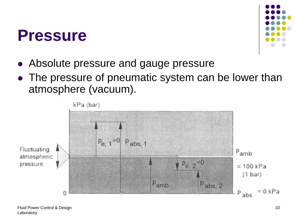
PressureAbsolute pressure and gauge pressureThe pressure of pneumatic system can be lower than atmosphere (vacuum).
Fluid Power Control & Design Laboratory
11
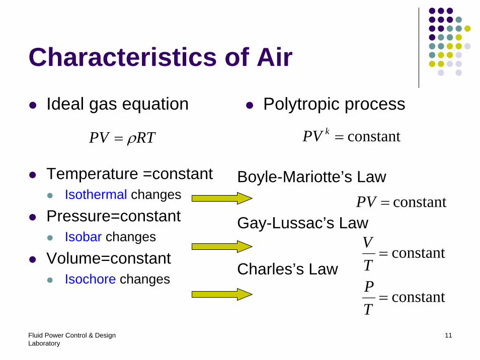
Characteristics of AirIdeal gas equation
Temperature =constantIsothermal changes
Pressure=constantIsobar changes
Volume=constantIsochore changes
Boyle-Mariotte’s Law
Gay-Lussac’s Law
Charles’s Law
constant=PV
constant=TV
constant=TP
RTPV ρ=
Polytropic process
constant=kPV
Fluid Power Control & Design Laboratory
12
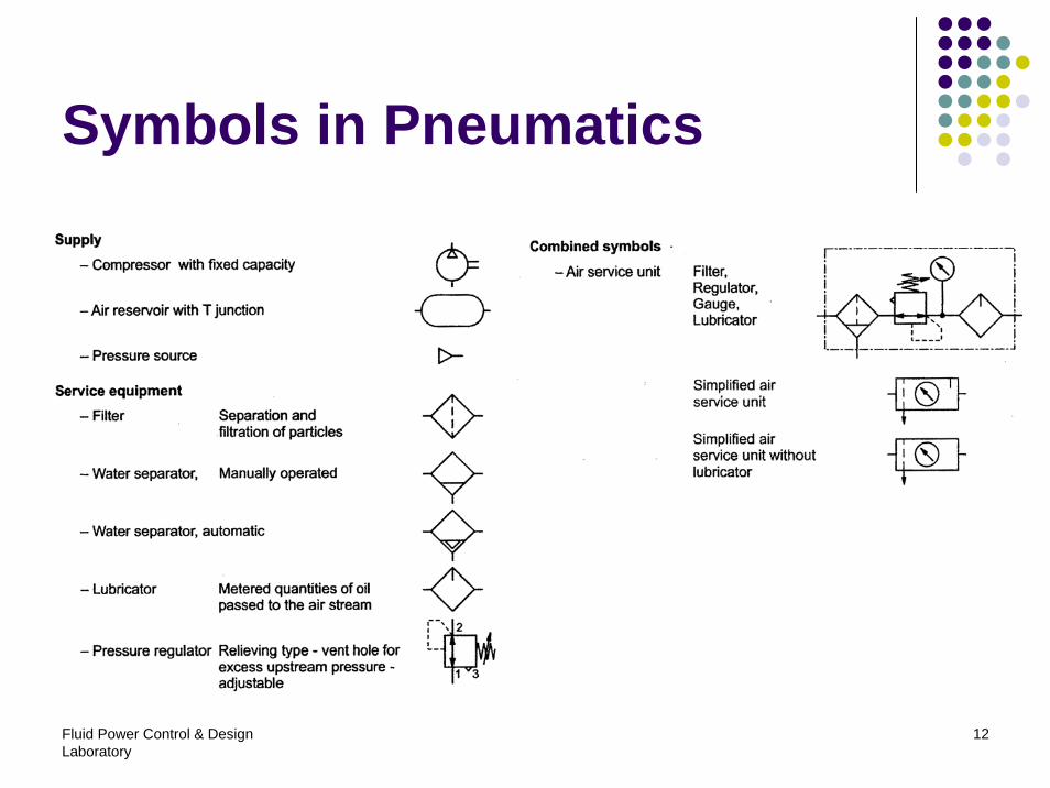
Symbols in Pneumatics
Fluid Power Control & Design Laboratory
13
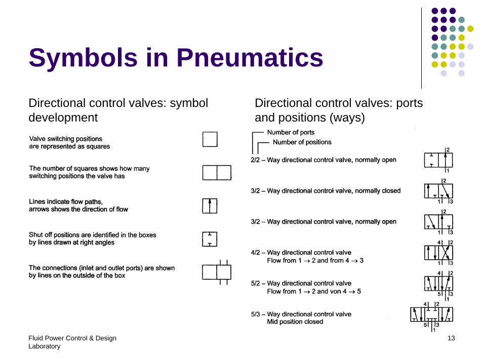
Symbols in PneumaticsDirectional control valves: symbol development
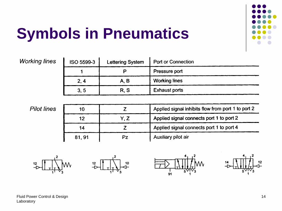
Directional control valves: ports and positions (ways)
Fluid Power Control & Design Laboratory
14
Symbols in Pneumatics
Fluid Power Control & Design Laboratory
15
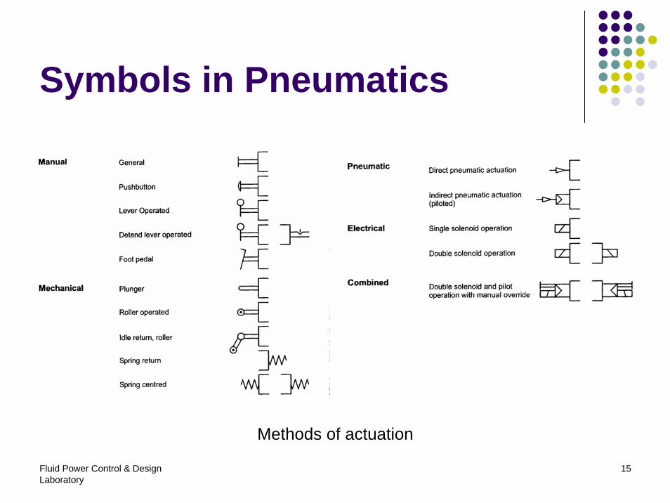
Symbols in Pneumatics
Methods of actuation
Fluid Power Control & Design Laboratory
16
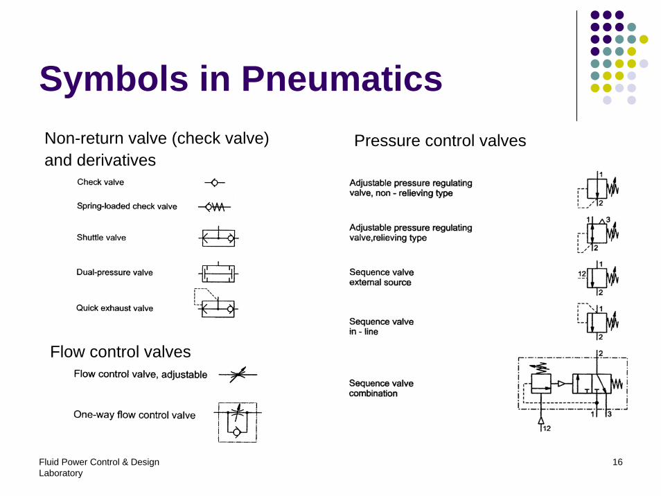
Symbols in PneumaticsNon-return valve (check valve)and derivatives
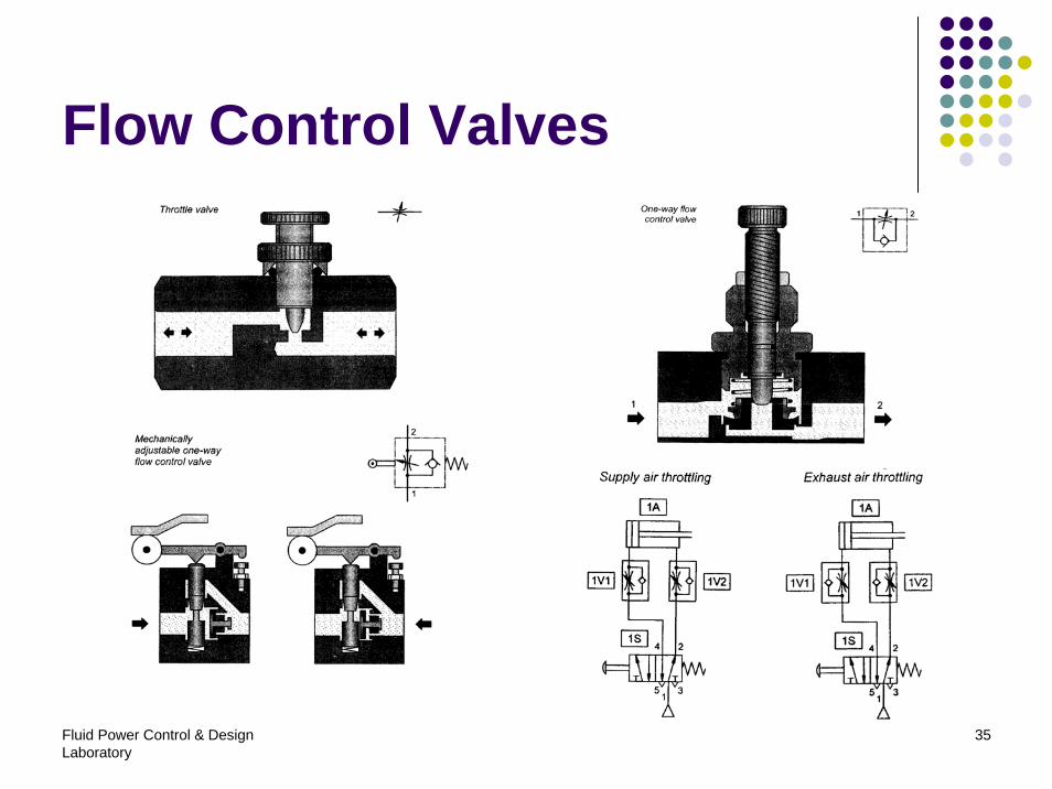
Flow control valves
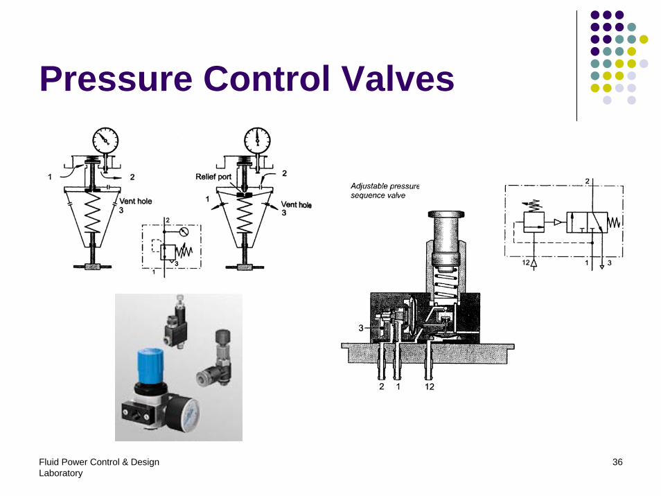
Pressure control valves
Fluid Power Control & Design Laboratory
17
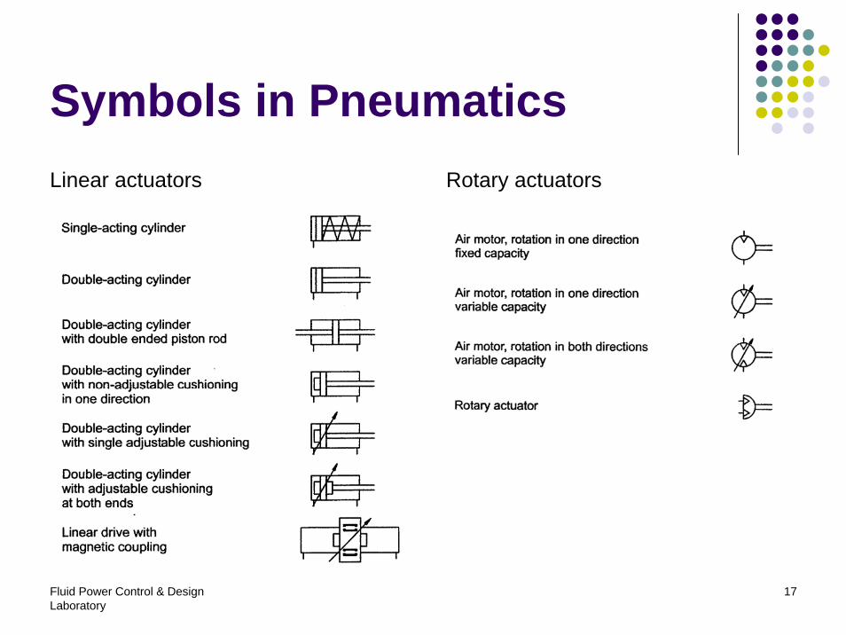
Symbols in PneumaticsLinear actuators Rotary actuators
Fluid Power Control & Design Laboratory
18
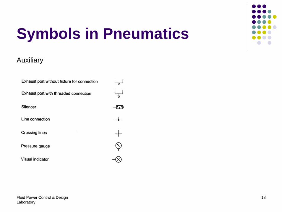
Symbols in PneumaticsAuxiliary
Fluid Power Control & Design Laboratory
19
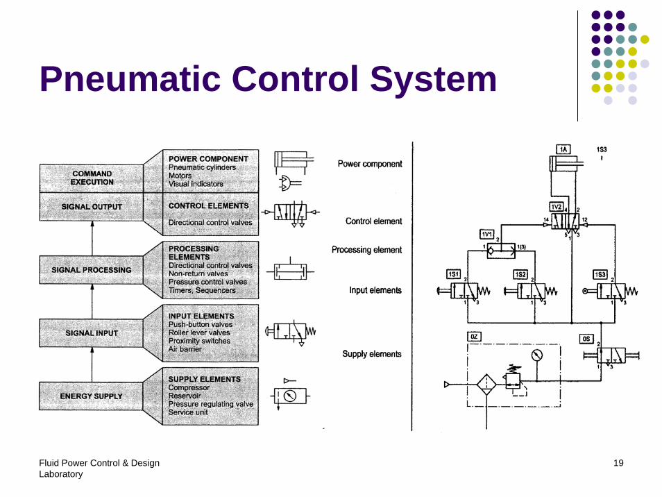
Pneumatic Control System
Fluid Power Control & Design Laboratory
20
Contents
1. Introduction2. Fundamentals3. Air generation4. Pneumatic actuators5. Pneumatic valves6. Vacuum technology7. Typical circuit
Fluid Power Control & Design Laboratory
21
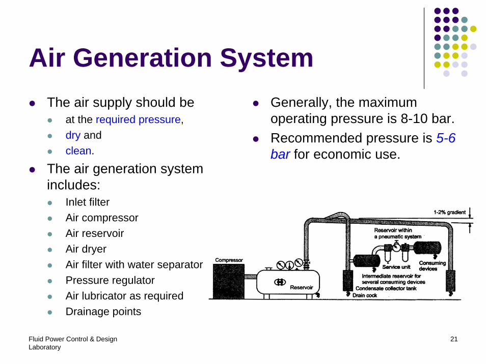
Air Generation SystemThe air supply should be
at the required pressure,dry andclean.
The air generation system includes:
Inlet filterAir compressorAir reservoirAir dryerAir filter with water separatorPressure regulatorAir lubricator as requiredDrainage points
Generally, the maximum operating pressure is 8-10 bar.Recommended pressure is 5-6 bar for economic use.
Fluid Power Control & Design Laboratory
22
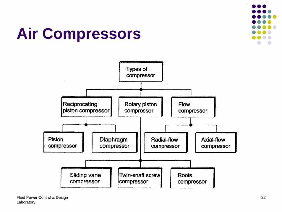
Air Compressors
Fluid Power Control & Design Laboratory
23
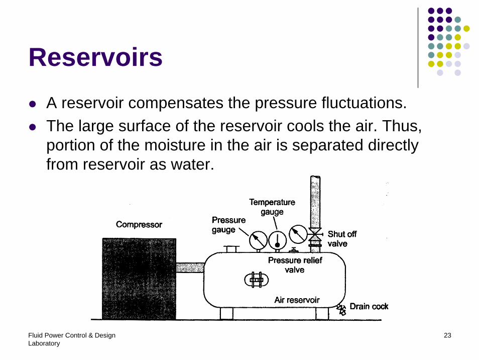
ReservoirsA reservoir compensates the pressure fluctuations.The large surface of the reservoir cools the air. Thus, portion of the moisture in the air is separated directly from reservoir as water.
Fluid Power Control & Design Laboratory
24
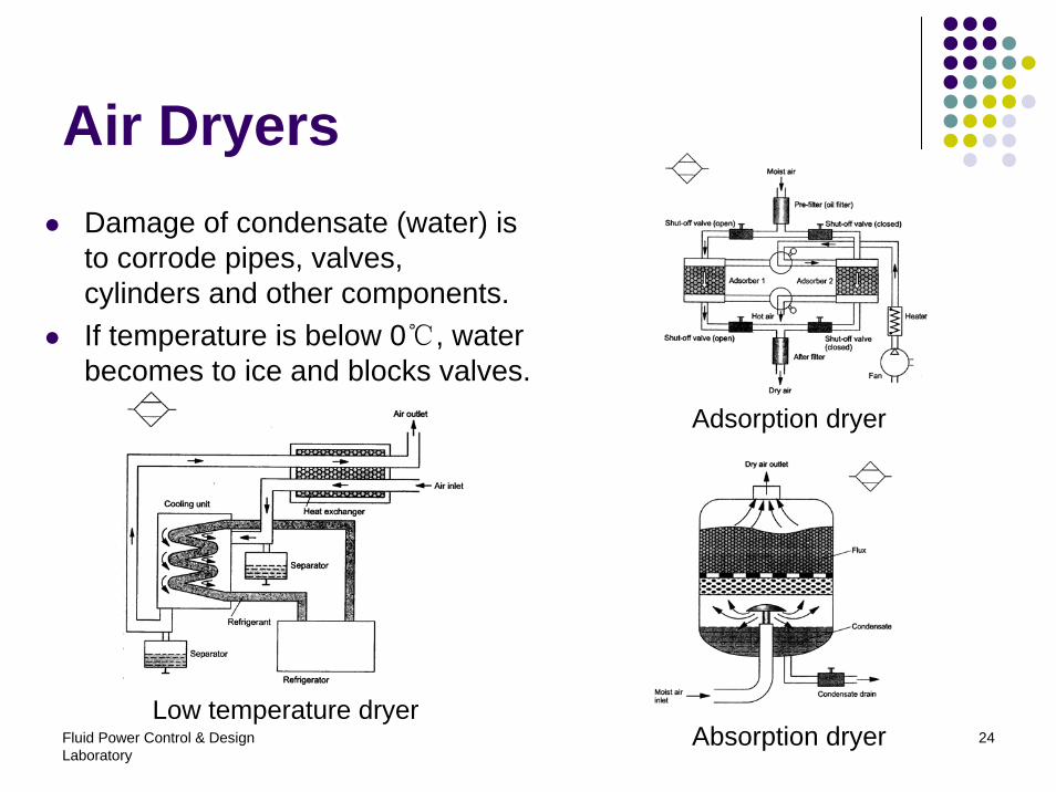
Air DryersDamage of condensate (water) is to corrode pipes, valves, cylinders and other components.If temperature is below 0℃, water becomes to ice and blocks valves.
Low temperature dryer
Adsorption dryer
Absorption dryer
Fluid Power Control & Design Laboratory
25
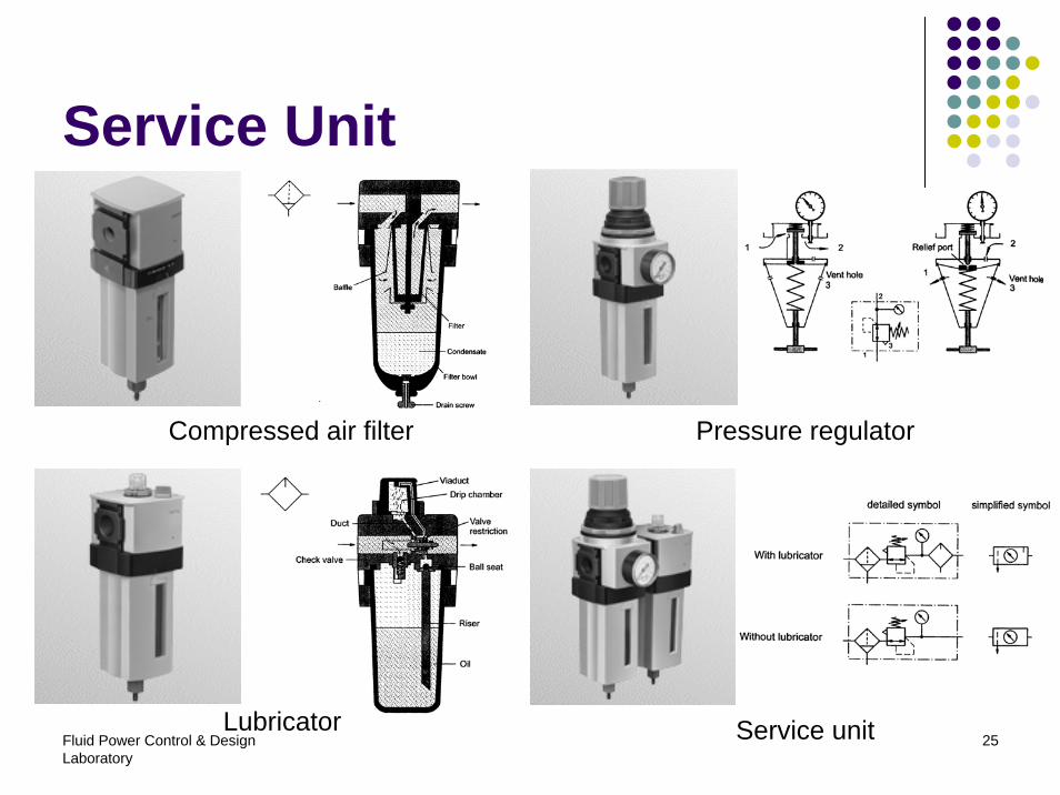
Service Unit
Compressed air filter
Lubricator
Pressure regulator
Service unit
Fluid Power Control & Design Laboratory
26
Contents
1. Introduction2. Fundamentals3. Air generation4. Pneumatic actuators5. Pneumatic valves6. Vacuum technology7. Typical circuit

Fluid Power Control & Design Laboratory
27
Single-acting Cylinders
Fluid Power Control & Design Laboratory
28
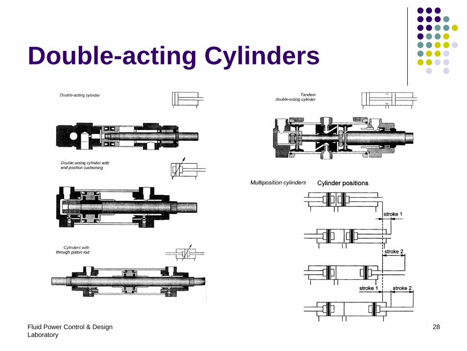
Double-acting Cylinders
Fluid Power Control & Design Laboratory
29
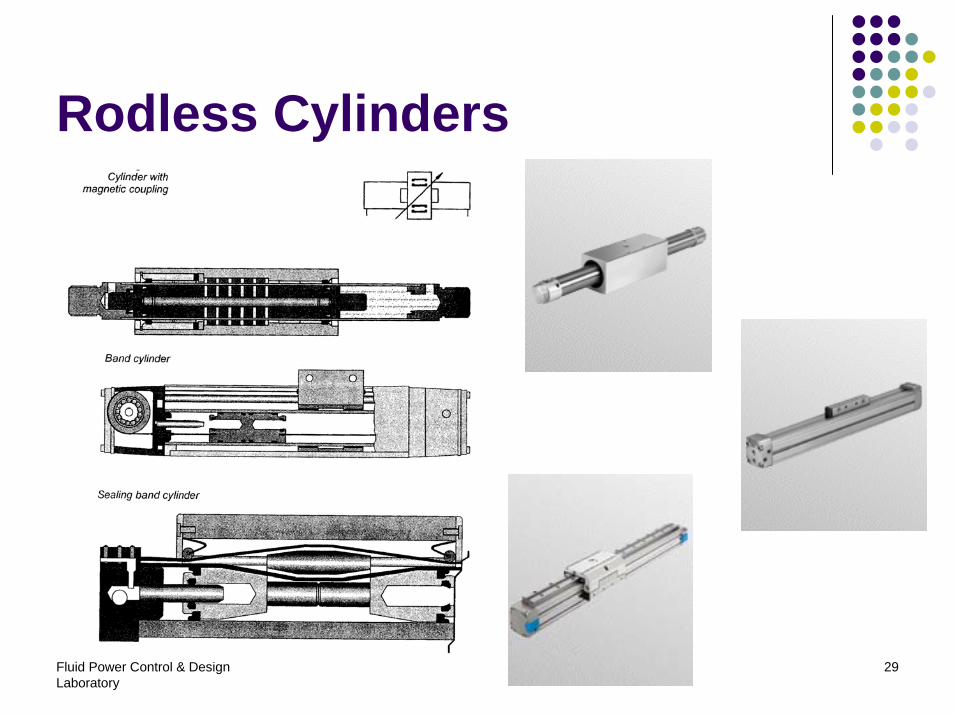
Rodless Cylinders
Fluid Power Control & Design Laboratory
30
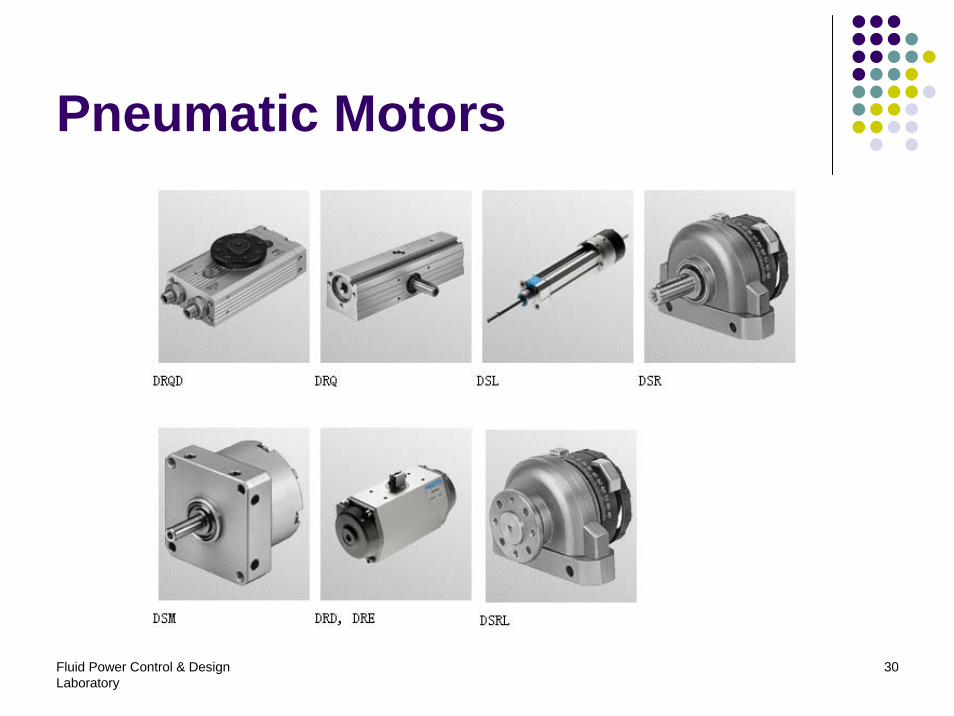
Pneumatic Motors
Fluid Power Control & Design Laboratory
31
Contents
1. Introduction2. Fundamentals3. Air generation4. Pneumatic actuators5. Pneumatic valves6. Vacuum technology7. Typical circuit
Fluid Power Control & Design Laboratory
32
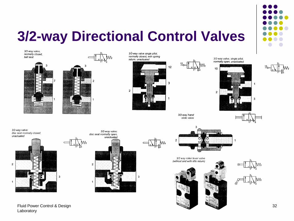
3/2-way Directional Control Valves
Fluid Power Control & Design Laboratory
33
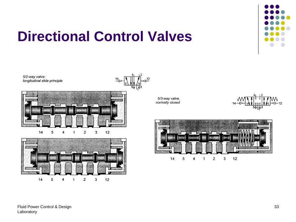
Directional Control Valves
Fluid Power Control & Design Laboratory
34
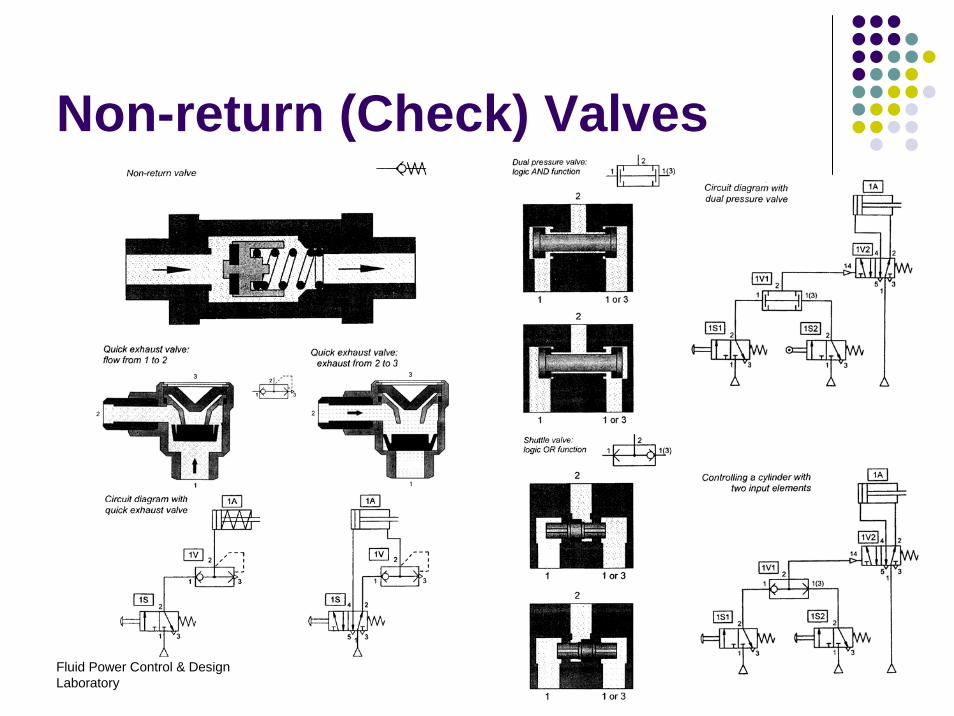
Non-return (Check) Valves
Fluid Power Control & Design Laboratory
35
Flow Control Valves
Fluid Power Control & Design Laboratory
36
Pressure Control Valves
Fluid Power Control & Design Laboratory
37
Contents
1. Introduction2. Fundamentals3. Air generation4. Pneumatic actuators5. Pneumatic valves6. Vacuum technology7. Typical circuit
Fluid Power Control & Design Laboratory
38
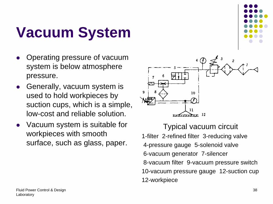
Vacuum SystemOperating pressure of vacuum system is below atmosphere pressure.Generally, vacuum system is used to hold workpieces by suction cups, which is a simple, low-cost and reliable solution.Vacuum system is suitable for workpieces with smooth surface, such as glass, paper.
Typical vacuum circuit1-filter 2-refined filter 3-reducing valve4-pressure gauge 5-solenoid valve6-vacuum generator 7-silencer8-vacuum filter 9-vacuum pressure switch10-vacuum pressure gauge 12-suction cup12-workpiece
Fluid Power Control & Design Laboratory
39
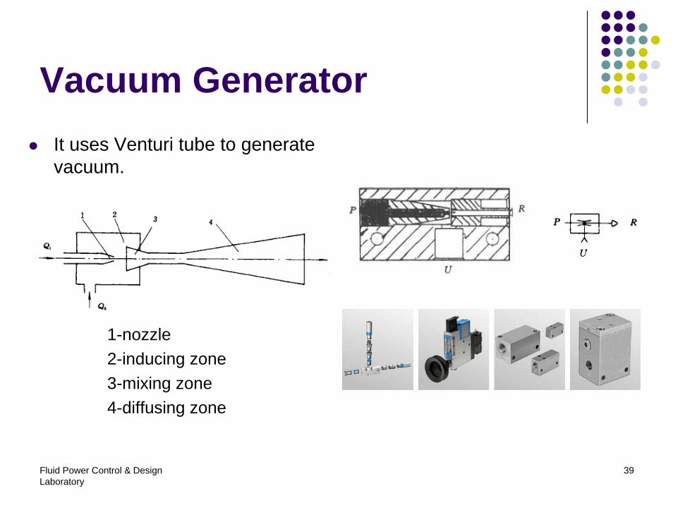
Vacuum GeneratorIt uses Venturi tube to generate vacuum.
1-nozzle2-inducing zone3-mixing zone4-diffusing zone
Fluid Power Control & Design Laboratory
40
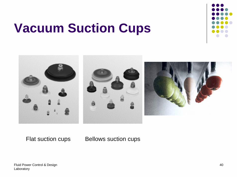
Vacuum Suction Cups
Flat suction cups Bellows suction cups
Fluid Power Control & Design Laboratory
41
Contents
1. Introduction2. Fundamentals3. Air generation4. Pneumatic actuators5. Pneumatic valves6. Vacuum technology7. Typical circuit
Fluid Power Control & Design Laboratory
42
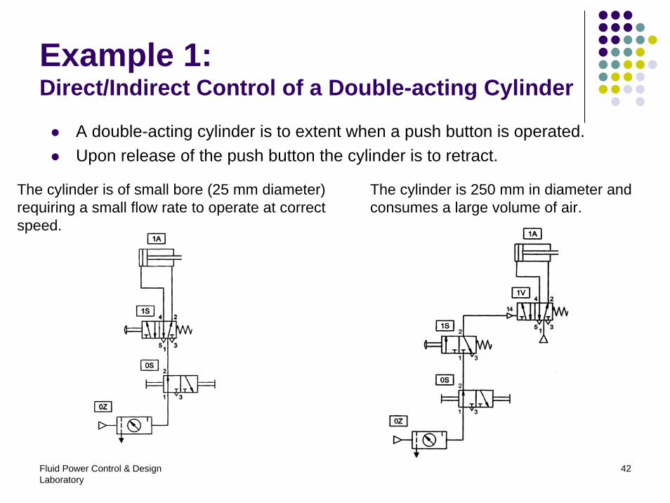
Example 1:Direct/Indirect Control of a Double-acting Cylinder
A double-acting cylinder is to extent when a push button is operated.Upon release of the push button the cylinder is to retract.
The cylinder is of small bore (25 mm diameter) requiring a small flow rate to operate at correct speed.
The cylinder is 250 mm in diameter and consumes a large volume of air.
Fluid Power Control & Design Laboratory
43
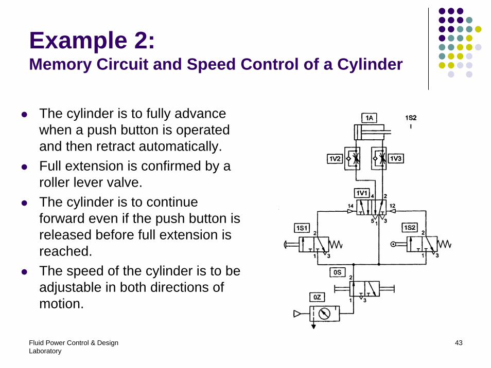
Example 2:Memory Circuit and Speed Control of a Cylinder
The cylinder is to fully advance when a push button is operated and then retract automatically.Full extension is confirmed by a roller lever valve.The cylinder is to continue forward even if the push button is released before full extension is reached.The speed of the cylinder is to be adjustable in both directions of motion.
Fluid Power Control & Design Laboratory
44
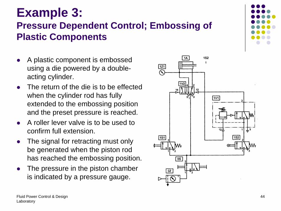
Example 3:Pressure Dependent Control; Embossing of Plastic Components
A plastic component is embossed using a die powered by a double-acting cylinder.The return of the die is to be effected when the cylinder rod has fully extended to the embossing position and the preset pressure is reached.A roller lever valve is to be used to confirm full extension.The signal for retracting must only be generated when the piston rod has reached the embossing position.The pressure in the piston chamber is indicated by a pressure gauge.
Fluid Power Control & Design Laboratory
45
References
1. Peter Croser, Frank Ebel, Pneumatics (Basic Level), Festo Didactic, 2002
2. Festo catalog, 2003/2004