Interaction Regions Working Group (T1) Final Report T.Markiewicz, F.Pilat Plenary Session Snowmass,...
27
Interaction Regions Working Group (T1) Final Report T.Markiewicz, F.Pilat Plenary Session Snowmass, July 19
-
Upload
pamela-samford -
Category
Documents
-
view
217 -
download
3
Transcript of Interaction Regions Working Group (T1) Final Report T.Markiewicz, F.Pilat Plenary Session Snowmass,...
Interaction Regions Working Group (T1)
Final ReportT.Markiewicz, F.Pilat
Plenary SessionSnowmass, July 19
Overview
IntroductionHadron collidersLepton-hadron e+e- linear colliderse+e- ring colliders collidersConclusions
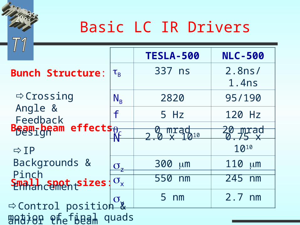
Basic LC IR Drivers
Bunch Structure:
Beam-beam effects
Small spot sizes:
TESLA-500 NLC-500
B 337 ns 2.8ns/1.4ns
NB 2820 95/190
f 5 Hz 120 Hz
C 0 mrad 20 mrad
x550 nm 245 nm
y5 nm 2.7 nm
N 2.0 x 10¹⁰ 0.75 x 10¹⁰
z300 m 110 m
Crossing Angle & Feedback Design
IP Backgrounds & Pinch Enhancement
Control position & motion of final quads and/or the beam
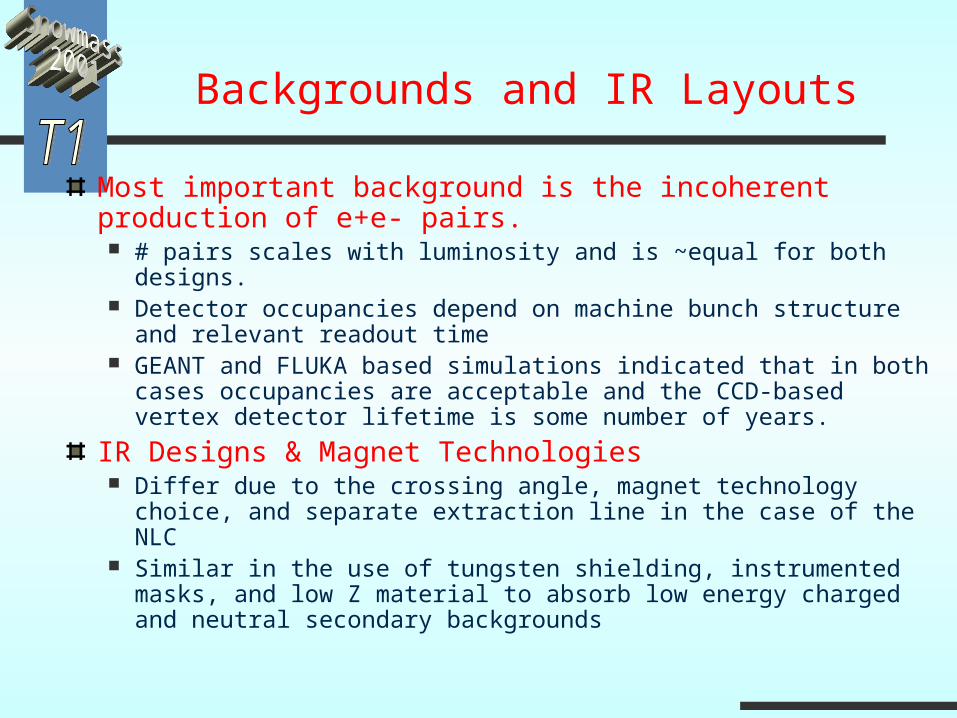
Backgrounds and IR Layouts
Most important background is the incoherent production of e+e- pairs. # pairs scales with luminosity and is ~equal for both
designs. Detector occupancies depend on machine bunch structure
and relevant readout time GEANT and FLUKA based simulations indicated that in
both cases occupancies are acceptable and the CCD-based vertex detector lifetime is some number of years.
IR Designs & Magnet Technologies Differ due to the crossing angle, magnet technology
choice, and separate extraction line in the case of the NLC Similar in the use of tungsten shielding, instrumented
masks, and low Z material to absorb low energy charged and neutral secondary backgrounds

e+,e- pairs from beams. interactions
are the most important background
# scales w/ L
2.5-5x10⁹/sec
BSOL, L*,& Masks
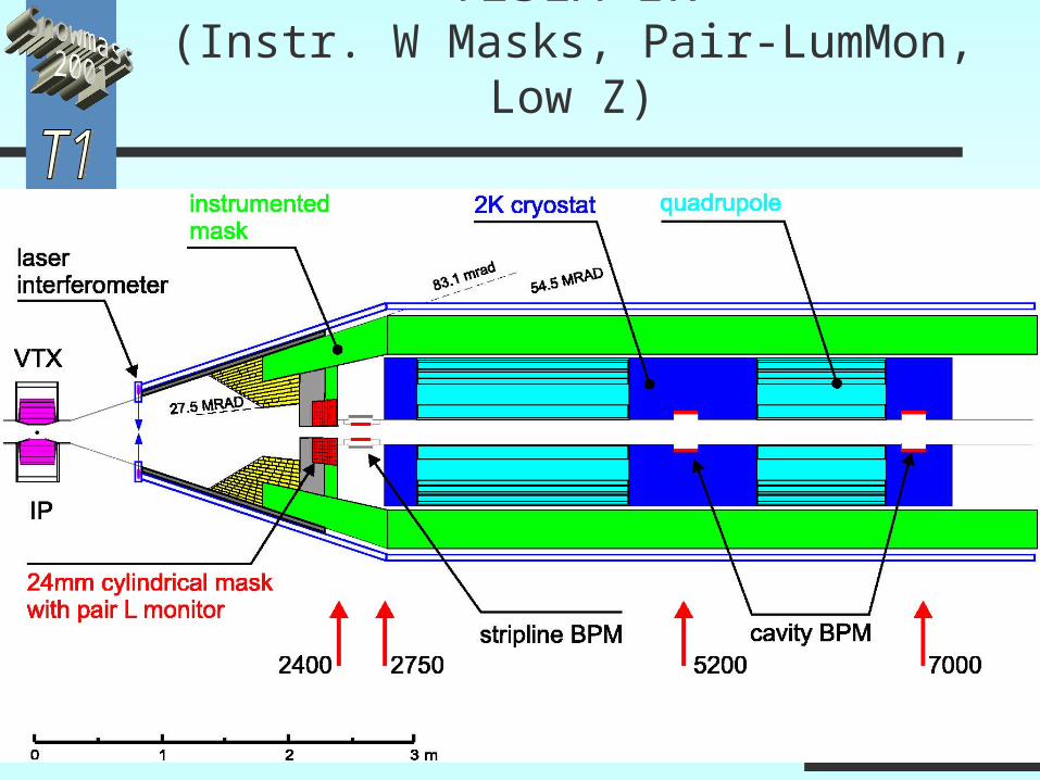
TESLA IR(Instr. W Masks, Pair-LumMon, Low
Z)
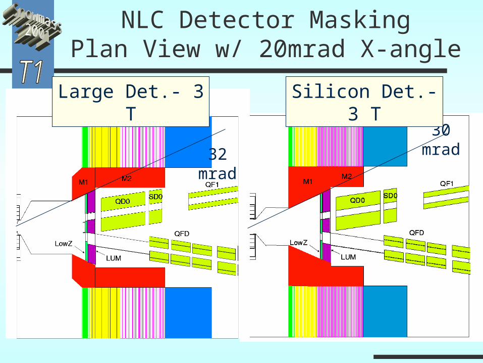
NLC Detector MaskingPlan View w/ 20mrad X-angle
32 mrad
30 mrad
Large Det.- 3 T Silicon Det.- 3 T
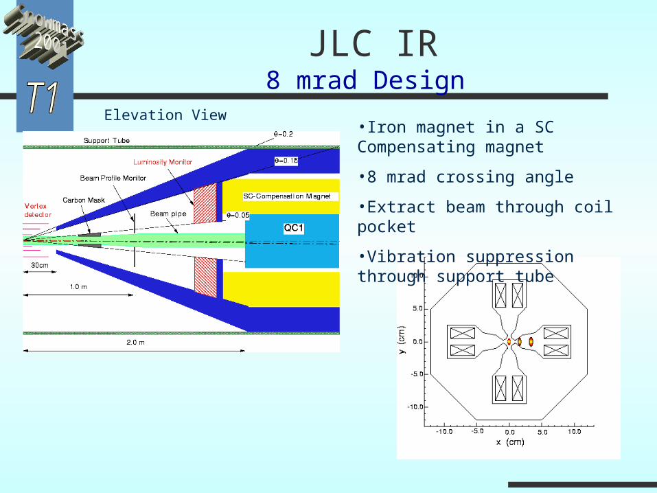
Elevation View•Iron magnet in a SC Compensating magnet
•8 mrad crossing angle
•Extract beam through coil pocket
•Vibration suppression through support tube
JLC IR8 mrad Design
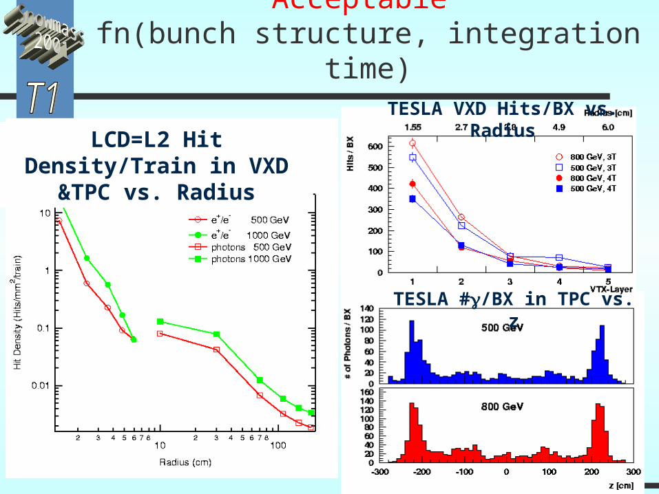
Detector Occupancies are Acceptable fn(bunch structure, integration time)
LCD=L2 Hit Density/Train in VXD &TPC vs. Radius
TESLA VXD Hits/BX vs. Radius
TESLA #/BX in TPC vs. z
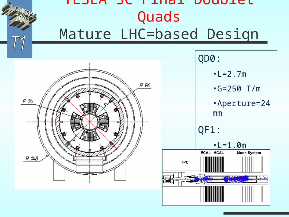
TESLA SC Final Doublet QuadsMature LHC=based Design
QD0:
•L=2.7m
•G=250 T/m
•Aperture=24mm
QF1:
•L=1.0m
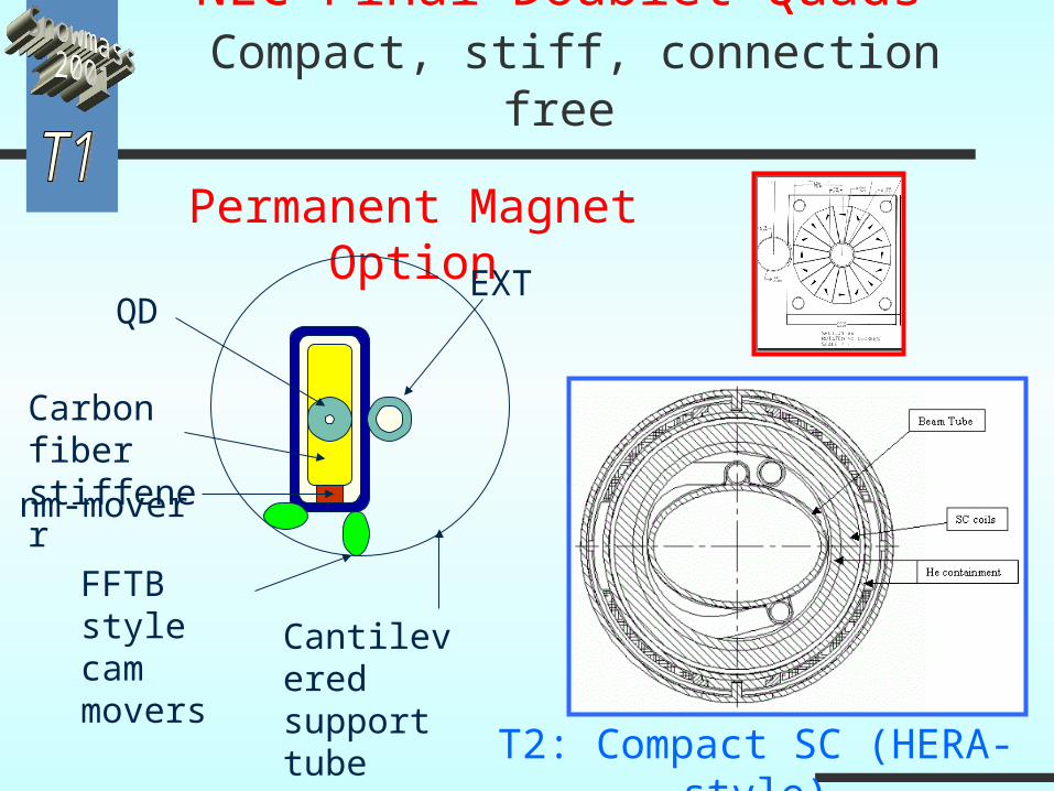
NLC Final Doublet Quads Compact, stiff, connection free
Permanent Magnet Option
T2: Compact SC (HERA-style)
QD
Carbon fiber stiffener
Cantilevered support tube
FFTB style cam movers
nm-mover
EXT
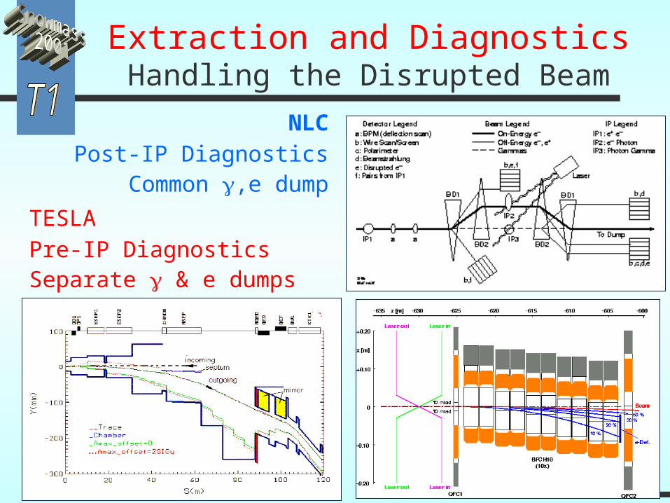
Extraction and DiagnosticsHandling the Disrupted Beam
NLCPost-IP DiagnosticsCommon ,e dump
TESLAPre-IP DiagnosticsSeparate & e dumps
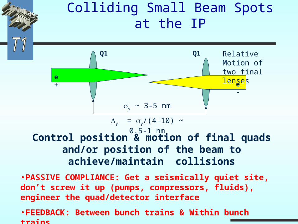
Colliding Small Beam Spots at the IP
Control position & motion of final quads and/or position of the beam to achieve/maintain collisions
•PASSIVE COMPLIANCE: Get a seismically quiet site, don’t screw it up (pumps, compressors, fluids), engineer the quad/detector interface
•FEEDBACK: Between bunch trains & Within bunch trains
•SENSE MOTION & CORRECT MAGNETS or BEAMS
y ~ 3-5 nm
y = y/(4-10) ~ 0.5-1 nm
Q1 Q1
e+e-
Relative Motion of two final lenses
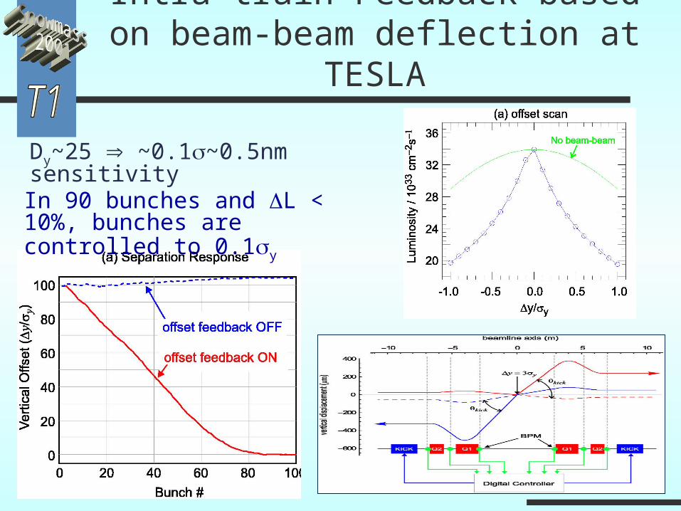
Intra-train Feedback based on beam-beam deflection at TESLA
In 90 bunches and L < 10%, bunches are controlled to 0.1y
Dy~25 ~0.1~0.5nm sensitivity
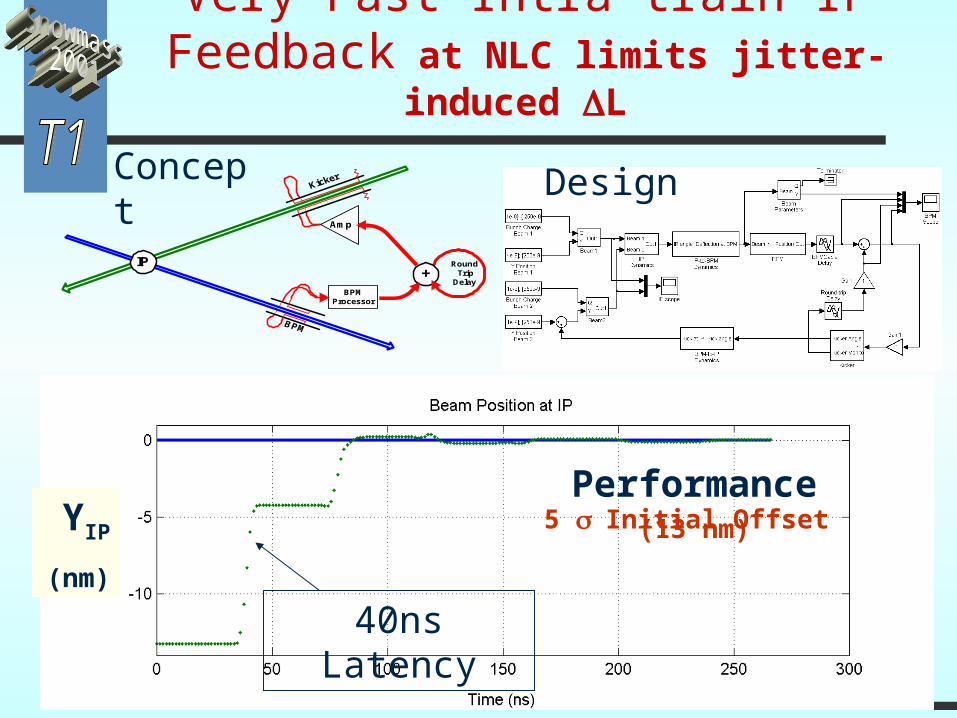
Very Fast Intra-train IP Feedback at NLC limits jitter-
induced L
Amp
BPMProcessor
IP Round Trip Delay
+
Amp
Concept
Performance5 Initial Offset (13 nm)
Design
40ns Latency
YIP
(nm)
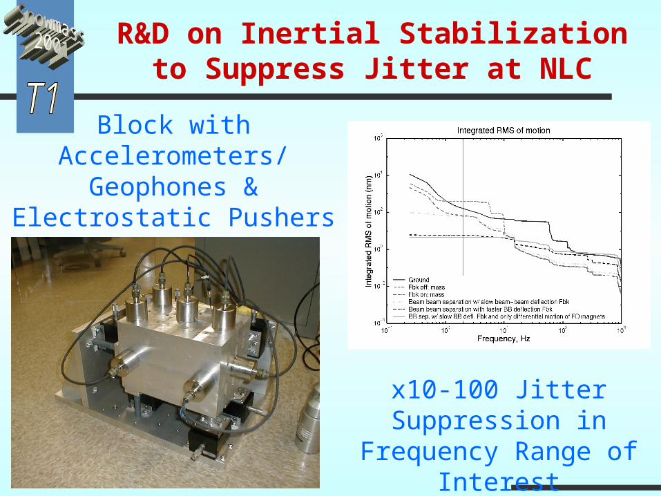
R&D on Inertial Stabilization to Suppress Jitter at NLC
Block with Accelerometers/
Geophones & Electrostatic Pushers
x10-100 Jitter Suppression in
Frequency Range of Interest
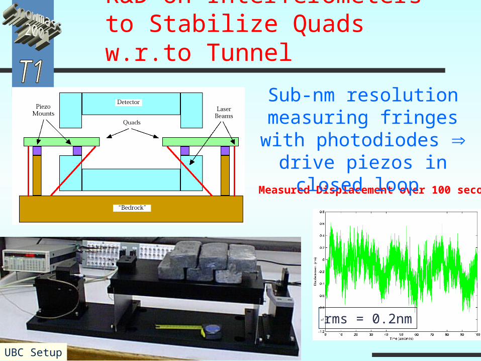
R&D on Interferometers to Stabilize Quads w.r.to Tunnel
UBC Setup
Measured Displacement over 100 seconds
rms = 0.2nm
Sub-nm resolution measuring fringes with
photodiodes drive piezos in closed loop
Collider IR
Laser Development Fusion program-funded “Mercury” laser project
applicable to project is under construction Conceptual designs to take the output of the laser
and to match it to the time structure required for either the NLC or TESLA are underway
IR Optical designs to provide the e collisions have been developed and
will soon be tested.
Optics and IP parameters improved performance for collisions
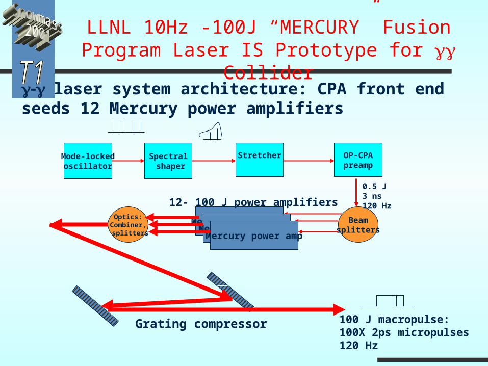
laser system architecture: CPA front endseeds 12 Mercury power amplifiers
Mode-lockedoscillator
Spectral shaper
Stretcher OP-CPApreamp
Mercury power ampMercury power amp
Mercury power amp
Beamsplitters
12- 100 J power amplifiersOptics:
Combiner, splitters
Grating compressor 100 J macropulse:100X 2ps micropulses120 Hz
0.5 J3 ns120 Hz
LLNL 10Hz -100J “MERCURY” Fusion Program Laser IS Prototype for Collider
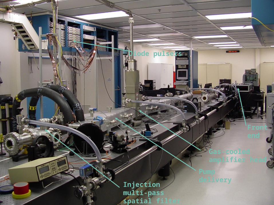
Pump delivery
Front end
Injection multi-pass spatial filter
Diode pulsers
Gas-cooled amplifier head
8 May 1999
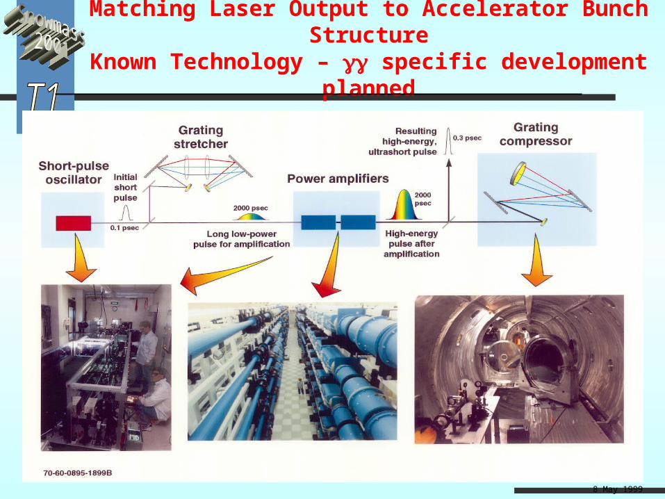
Matching Laser Output to Accelerator Bunch StructureKnown Technology – specific development planned
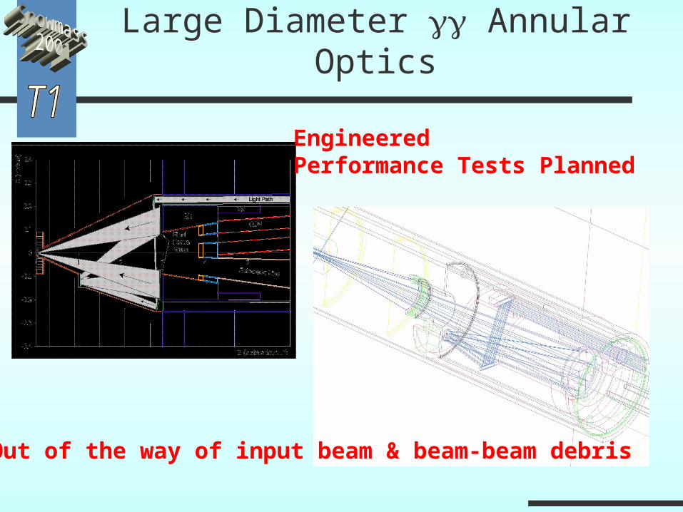
Large Diameter Annular Optics
EngineeredPerformance Tests Planned
Out of the way of input beam & beam-beam debris
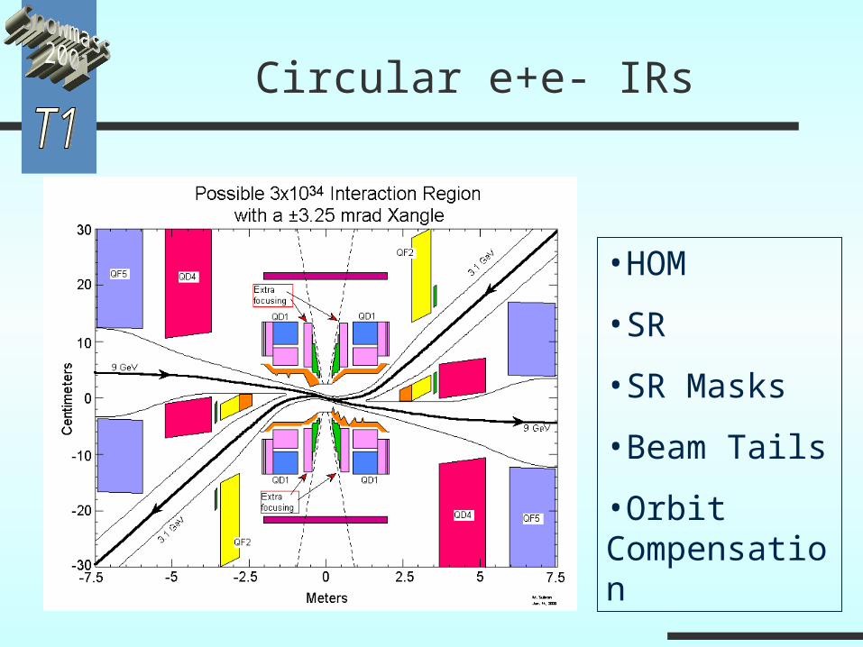
Circular e+e- IRs
•HOM
•SR
•SR Masks
•Beam Tails
•Orbit Compensation
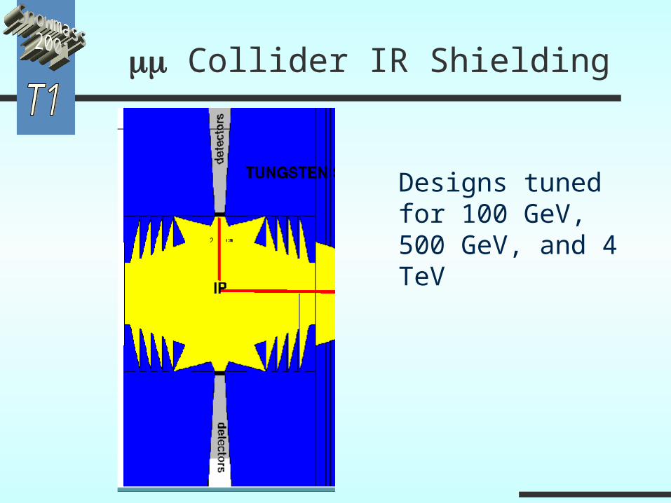
Collider IR Shielding
Designs tuned for 100 GeV, 500 GeV, and 4 TeV
Conclusions
Many IR design issues are common across different types of machines
The proposed designs for LC IRs look more similar than different, are fairly well advanced, and
have active R&D programs
Viable solutions to Laser & IR Optics now available and give program real credibility
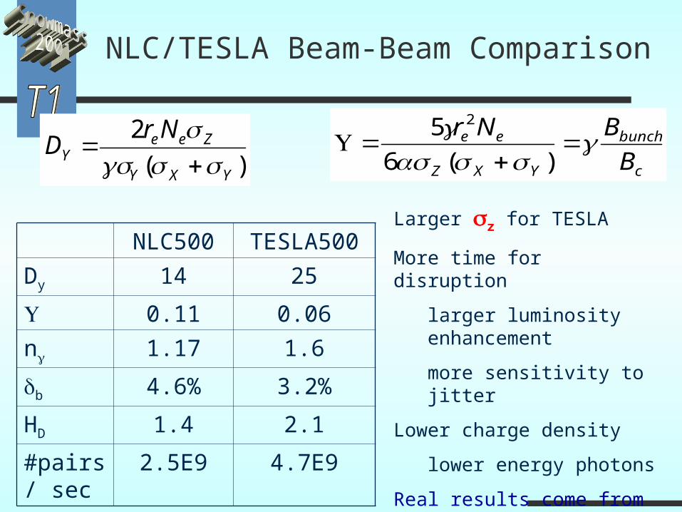
NLC/TESLA Beam-Beam Comparison
)(
2
YXY
ZeeY
NrD
c
bunch
YXZ
ee
B
BNr
)(6
5 2
NLC500 TESLA500
Dy 14 25
0.11 0.06
n 1.17 1.6
b 4.6% 3.2%
HD 1.4 2.1
#pairs/ sec
2.5E9 4.7E9
Larger z for TESLA
More time for disruption
larger luminosity enhancement
more sensitivity to jitter
Lower charge density
lower energy photons
Real results come from beam-beam sim. (Guinea-Pig/CAIN) and GEANT3/FLUKA
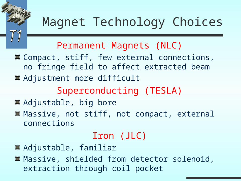
Magnet Technology Choices
Permanent Magnets (NLC)Compact, stiff, few external connections, no fringe field to affect extracted beamAdjustment more difficult
Superconducting (TESLA)Adjustable, big boreMassive, not stiff, not compact, external connections
Iron (JLC)Adjustable, familiarMassive, shielded from detector solenoid, extraction through coil pocket