INSTRUCTION MANUAL For 」で区切る。不要の場合は...
204
INSTRUCTION MANUAL For... 。 「/」 る。 る。 を 。 「/」 る。 3522-50 を 。 LCR HiTESTER
Transcript of INSTRUCTION MANUAL For 」で区切る。不要の場合は...
INSTRUCTION MANUALFor...は専用機種。複数の場合は「/」で区切る。不要の場合はとる。
形名を入力。 複数の場合は「/」で区切る。
3522-50品名を入力。
LCR HiTESTER
sharif_geraldizo
Tequipment

Contents
Introduction iShipping Check iiSafety iiiPoints for Attention During Use vLayout of This Manual vi
Chapter 1 Overview 11.1 Product Overview 11.2 Product Features 21.3 Names and Functions of Parts 3
Chapter 2 Before Starting Measurement 72.1 Connecting the Power Cord 72.2 Connecting the Test Leads 8
2.2.1 Establishing the Connections 82.3 Turning the Power On and Off 10
Chapter 3 Outline of Operation 113.1 About the Touch Panel 113.2 About the Screen 12
3.2.1 Control Screen Sequence 143.3 Basic Measurement 15
3.3.1 Basic Flow up to Testing of the Sample 153.3.2 Setting the Test Parameters to be Displayed (Cs, D) 163.3.3 Setting the Test Frequency 183.3.4 Setting the Constant Voltage Level 213.3.5 Setting Open Circuit Compensation 233.3.6 Setting Short Circuit Compensation 263.3.7 Starting Testing 28
Chapter 4 Detailed Description of Functions 294.1 Description of the Screens 29
4.1.1 The Initial Screen 304.1.2 The Menu Screen and Application Menu Screen 31
4.2 Setting the Parameters to be Displayed 324.2.1 Control Screen Sequence 324.2.2 Details of the Setting Process 324.2.3 Series Equivalent Circuit Mode and Parallel Equivalent
Circuit Mode 34
4.3 Setting the Test Frequency 354.3.1 Control Screen Sequence 354.3.2 Selecting the Input Method 364.3.3 Input Using the Ten Key Screen 374.3.4 Input Using the Digit Screen 38
4.4 Setting the Test Signal Level 394.4.1 Control Screen Sequence 394.4.2 Selecting the Level Type 404.4.3 Setting the Open Circuit Voltage (V) Level 424.4.4 Setting the Constant Voltage (CV) Level 434.4.5 Setting the Constant Current (CC) Level 44
4.5 Setting the Voltage/Current Limit 454.5.1 Control Screen Sequence 454.5.2 Details of the Setting Process 46
4.6 Setting the Ranging 484.6.1 Control Screen Sequence 484.6.2 Setting the Ranging 494.6.3 Setting AUTO Ranging 494.6.4 Setting the Ranging to HOLD 50
4.7 Open Circuit Compensation 524.7.1 Control Screen Sequence 524.7.2 Setting the Compensation Method 534.7.3 ALL Compensation 544.7.4 Spot Compensation 564.7.5 When an Error Message Appears and Compensation
Has Stopped 594.7.6 Clearing Compensation Data 59
4.8 Short Circuit Compensation 604.8.1 Control Screen Sequence 604.8.2 Setting the Compensation Method 614.8.3 ALL Compensation 634.8.4 Spot Compensation 654.8.5 When an Error Message Appears and
Compensation Has Stopped 684.8.6 Clearing Compensation Data 68
4.9 Open Circuit Compensation and Short CircuitCompensation 69
4.10 Setting the Trigger 714.10.1 Control Screen Sequence 714.10.2 Details of the Setting Process 72
4.11 Setting the Trigger Delay 744.11.1 Control Screen Sequence 744.11.2 Details of the Setting Process 75
4.12 Setting Averaging 774.12.1 Control Screen Sequence 774.12.2 Details of the Setting Process 78
4.13 Setting the Testing Speed 804.13.1 Control Screen Sequence 804.13.2 Details of the Setting Process 81
4.14 Setting and Activating the Comparator 824.14.1 Control Screen Sequence 834.14.2 Setting the Comparator 834.14.3 Returning from Comparator Operation to Normal
Testing 864.14.4 Choosing How to Set the Upper and Lower Limit
Values 864.14.5 Setting the Upper or Lower Limit Value as
an Absolute Value (ABS) 884.14.6 Setting the Upper or Lower Limit Value as
a Percentage (%) Relative to a Standard Value 904.14.7 Displaying Measurement Values as Deviations from
the Reference value (∆%) 934.15 Setting and Activating the Scaling 95
4.15.1 Control Screen Sequence 954.15.2 Setting Scaling 964.15.3 Canceling the Scaling Function 974.15.4 Setting the Compensation Coefficient (a, b) 98
4.16 Panel Save Function 1004.16.1 Control Screen Sequence 1004.16.2 Details of the Setting Process 101
4.17 Panel Load Function 1044.17.1 Control Screen Sequence 1044.17.2 Details of the Setting Process 105
4.18 Setting the Beep Sound 1074.18.1 Control Screen Sequence 1074.18.2 Details of the Setting Process 108
4.19 Enlarged Display of Measurement Values 1094.19.1 Control Screen Sequence 1094.19.2 Details of the Setting Process 110
4.20 System Reset 1114.20.1 Control Screen Sequence 1114.20.2 Details of the Setting Process 112
4.21 Continuous Test Function 1144.21.1 Control Screen Sequence 1144.21.2 Details of the Setting Process 115
4.22 External DC Bias Setting 1184.22.1 Control Screen Sequence 1184.22.2 Details of the Setting Process 119
4.23 Setting the Number of Displayed Digits 1204.23.1 Control Screen Sequence 1204.23.2 Details of the Setting Process 121
4.24 Setting for Display 1224.24.1 Control Screen Sequence 1224.24.2 Details of the Setting Process 123
4.25 Key Lock Function 1244.25.1 Turning the Key Lock On and Off 124
Chapter 5 Applications 1255.1 Example of Comparator Application 1255.2 Testing High Impedance Elements 1275.3 Testing an Element in a Circuit 1285.4 External Interference 129
5.4.1 Countermeasures Against Interference from thePower Supply Line 129
5.4.2 Countermeasures Against Noise from the TestCables 131
5.5 The EXT I/O Connector 1325.5.1 Pinouts for the EXT I/O Connector 1335.5.2 Signal Lines for the EXT I/O Connector 1345.5.3 Circuit Construction and Connections for the EXT I/O
Connector 1365.5.4 Electrical Characteristics of the Output Signals 137
5.6 Testing Using EXT I/O 1385.6.1 Normal Testing 1385.6.2 Continuous Testing From EXT I/O 140
5.7 Supplying DC Bias 1455.7.1 How to Supply a DC Bias Voltage 1455.7.2 How to Supply a DC Bias Current 147
5.8 The Residual Charge Protection Function 1485.9 9442 PRINTER (option) 149
5.9.1 Preparation 1495.9.2 Connection Method 1515.9.3 Control Screen Sequence 152
5.9.4 Returning from Comparator Operation to NormalTesting 153
5.9.5 Screen Copy Mode 1545.9.6 Auto Print Mode 1555.9.7 Manual Print Mode 155
Chapter 6 Maintenance, Adjustment, and Disposal 1576.1 Maintenance and Servicing 1576.2 How to Change the Power Supply Fuse and Change
the Power Supply Voltage 1596.3 Shipping the Unit 1616.4 Troubleshooting Checklist 1626.5 Disposing of the Unit 163
Chapter 7 Specification and Options 1657.1 General Specification 1657.2 Testing Parameters and Calculation Equations 1707.3 Time Taken for Testing 1727.4 Options 1767.5 Test Accuracy 179
Index INDEX 1


i
Introduction
Thank you for purchasing the HIOKI "3522-50 LCR HiTESTER." To obtainmaximum performance from the product, please read this manual first, andkeep it handy for future reference.
This manual contains information and points for attention which arenecessary for safe operation of the unit and for storing it safely in properoperational condition.
ii
NOTE
Shipping Check
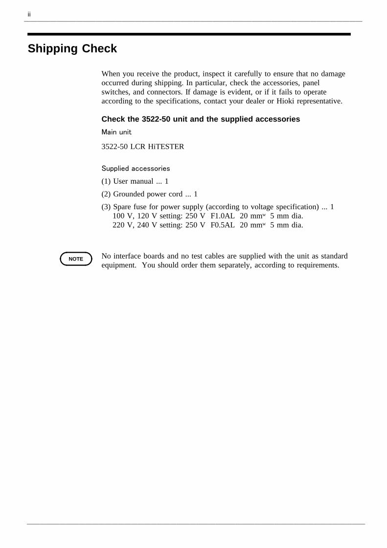
When you receive the product, inspect it carefully to ensure that no damageoccurred during shipping. In particular, check the accessories, panelswitches, and connectors. If damage is evident, or if it fails to operateaccording to the specifications, contact your dealer or Hioki representative.
Check the 3522-50 unit and the supplied accessoriesMain unit
3522-50 LCR HiTESTER
Supplied accessories
(1) User manual ... 1(2) Grounded power cord ... 1(3) Spare fuse for power supply (according to voltage specification) ... 1
100 V, 120 V setting: 250 V F1.0AL 20 mm×5 mm dia.220 V, 240 V setting: 250 V F0.5AL 20 mm×5 mm dia.
No interface boards and no test cables are supplied with the unit as standardequipment. You should order them separately, according to requirements.
iii
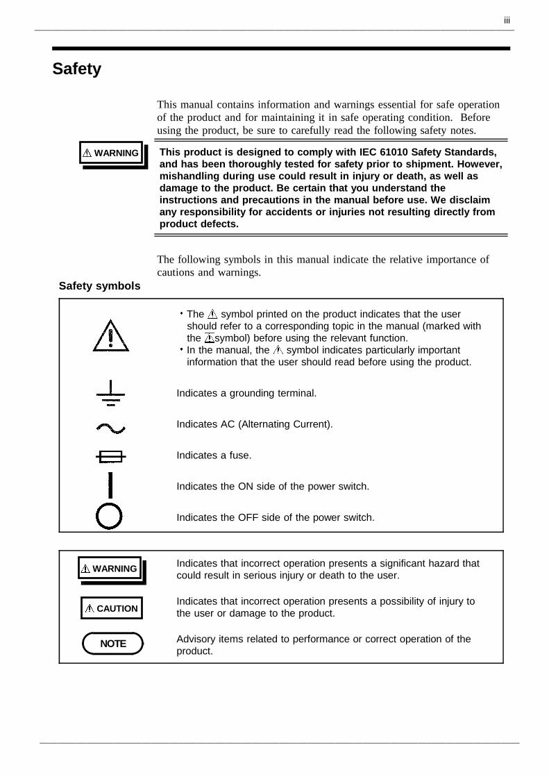
WARNING This product is designed to comply with IEC 61010 Safety Standards,and has been thoroughly tested for safety prior to shipment. However,mishandling during use could result in injury or death, as well asdamage to the product. Be certain that you understand theinstructions and precautions in the manual before use. We disclaimany responsibility for accidents or injuries not resulting directly fromproduct defects.
Safety symbols
The symbol printed on the product indicates that the usershould refer to a corresponding topic in the manual (marked withthe symbol) before using the relevant function.In the manual, the symbol indicates particularly importantinformation that the user should read before using the product.
Indicates a grounding terminal.
Indicates AC (Alternating Current).
Indicates a fuse.
Indicates the ON side of the power switch.
Indicates the OFF side of the power switch.
WARNING Indicates that incorrect operation presents a significant hazard thatcould result in serious injury or death to the user.
CAUTIONIndicates that incorrect operation presents a possibility of injury tothe user or damage to the product.
NOTE Advisory items related to performance or correct operation of theproduct.
Safety
This manual contains information and warnings essential for safe operationof the product and for maintaining it in safe operating condition. Beforeusing the product, be sure to carefully read the following safety notes.
The following symbols in this manual indicate the relative importance ofcautions and warnings.
iv
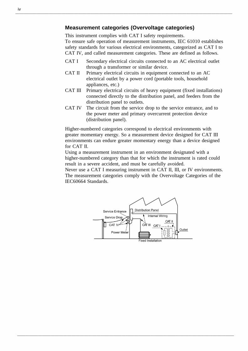
Measurement categories (Overvoltage categories)This instrument complies with CAT I safety requirements.To ensure safe operation of measurement instruments, IEC 61010 establishessafety standards for various electrical environments, categorized as CAT I toCAT IV, and called measurement categories. These are defined as follows.CAT I Secondary electrical circuits connected to an AC electrical outlet
through a transformer or similar device.CAT II Primary electrical circuits in equipment connected to an AC
electrical outlet by a power cord (portable tools, householdappliances, etc.)
CAT III Primary electrical circuits of heavy equipment (fixed installations)connected directly to the distribution panel, and feeders from thedistribution panel to outlets.
CAT IV The circuit from the service drop to the service entrance, and tothe power meter and primary overcurrent protection device(distribution panel).
Higher-numbered categories correspond to electrical environments withgreater momentary energy. So a measurement device designed for CAT IIIenvironments can endure greater momentary energy than a device designedfor CAT II.Using a measurement instrument in an environment designated with ahigher-numbered category than that for which the instrument is rated couldresult in a severe accident, and must be carefully avoided.Never use a CAT I measuring instrument in CAT II, III, or IV environments.The measurement categories comply with the Overvoltage Categories of theIEC60664 Standards.
v
WARNING Before turning the product on, make sure the source voltagematches that indicated on the product's power connector.Connection to an improper supply voltage may damage the productand present an electrical hazard.To avoid electric shock and ensure safe operation, connect thepower cable to a grounded (3-contact) outlet.The 3522-50 contains certain interior components which are at veryhigh voltages. Never remove the cover of the unit, because to do sois very dangerous.
CAUTION Various connectors are present on the outside of the 3522-50. Neverconnect any cable to any of these connectors without first turning off thepower supply and removing the power cord. Moreover, check theconnections carefully in order to avoid any chance of setting up a shortcircuit etc..If anything unusual happens during operation of the unit, turn off thepower switch immediately and contact any HIOKI service facility for help,advice and service.This product should be installed and operated between 0 and 40 and80% RH or less, and less than 2000 m height.The unit should always be stored in a range of temperature and humidityfrom -10 to 55 , 80% RH or less.Do not store or use the product where it could be exposed to directsunlight, high temperature or humidity, or condensation. Under suchconditions, the product may be damaged and insulation may deteriorateso that it no longer meets specifications.To avoid damage to the product, protect it from vibration or shock duringtransport and handling, and be especially careful to avoid dropping.Do not use excessive force on the touch panel, and do not use sharpobjects that could damage the touch screen.Before using the product, make sure that the insulation on the probes isundamaged and that no bare conductors are improperly exposed. Usingthe product in such conditions could cause an electric shock. Replace thetest leads and probes specified by Hioki.Ventilation holes for heat radiation are provided on the side panels of theproduct. Leave sufficient space around the ventilation holes and installthe product with the holes unobstructed. Installation of the product withthe ventilation holes obstructed may cause a malfunction or fire.
Points for Attention During UseFollow these precautions to ensure safe operation and to obtain the fullbenefits of the various functions.
About the guaranteeYou should be aware that HIOKI cannot accept any responsibility directly orindirectly if the unit has been incorporated in some other system, or if it isresold to a third party.
vi
Layout of This Manual
Chapter 1 OverviewDescribes the product generally, and lists the parts and functions.
Chapter 2 Before Starting MeasurementHow to connect the power cord etc., and important precautions beforeoperation.
Chapter 3 Outline of OperationExplains the touch panel and basic testing.
Chapter 4 Detailed Description of FunctionsDetailed explanation of the functions.
Chapter 5 Detailed Description of ApplicationsVarious testing applications.
Chapter 6 Maintenance, Adjustment, and Disposal
Chapter 7 Specification and Options
Index
1
1.1 Product Overview
1
2
3
4
5
6
7
8
9
10
11
12
13
14
A
Chapter 1Overview
1.1 Product Overview
The HIOKI 3522-50 LCR HiTESTER is an impedance meter which uses atouch panel as the user interface. This interactive touch panel enablesextremely easy operation. The test frequency can be set DC and from 1mHz to 100 kHz at high resolution.
The values of a maximum of any four of the fourteen test parameters,including not only impedance |Z| and phase angle θ, but also L, C, and Retc., can be simultaneously displayed upon the screen.
Moreover, this widely applicable impedance meter can be set, not only to afloating voltage setting, but also to a constant voltage setting or a constantcurrent setting.
2
1.2 Product Features
1.2 Product FeaturesWide range of test frequenciesThe test frequency can be selected from a wide range - DC, 1 mHz to 100kHz - at high resolution. Frequency dependent assessment of electroniccomponents and materials, etc., is possible.
Constant voltage and constant current testingAssessment of dependence upon voltage or current is possible.
Outstanding operabilityAll control operations are initiated via a touch panel on the display. All thekeys currently available for use are shown on the display, and can beoperated interactively.
Simultaneous display of four parametersUp to four of the test parameters (such as L,C,R, etc.) can be displayedsimultaneously.
InterfaceUsing a computer, any required parameters can be captured
Changing settings without stopping measurementVarious background settings can be changed without stopping measurement(when an internal trigger is set).
3
1.3 Names and Functions of Parts
1
2
3
4
5
6
7
8
9
10
11
12
13
14
A
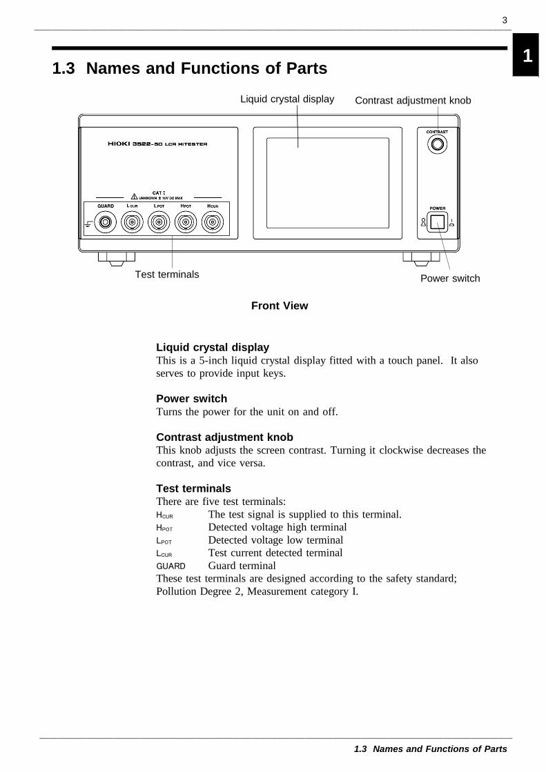
Test terminals
Contrast adjustment knob
Power switch
Liquid crystal display
Front View
1.3 Names and Functions of Parts
Liquid crystal displayThis is a 5-inch liquid crystal display fitted with a touch panel. It alsoserves to provide input keys.
Power switchTurns the power for the unit on and off.
Contrast adjustment knobThis knob adjusts the screen contrast. Turning it clockwise decreases thecontrast, and vice versa.
Test terminalsThere are five test terminals:HCUR The test signal is supplied to this terminal.HPOT Detected voltage high terminalLPOT Detected voltage low terminalLCUR Test current detected terminalGUARD Guard terminalThese test terminals are designed according to the safety standard;Pollution Degree 2, Measurement category I.
4
1.3 Names and Functions of Parts
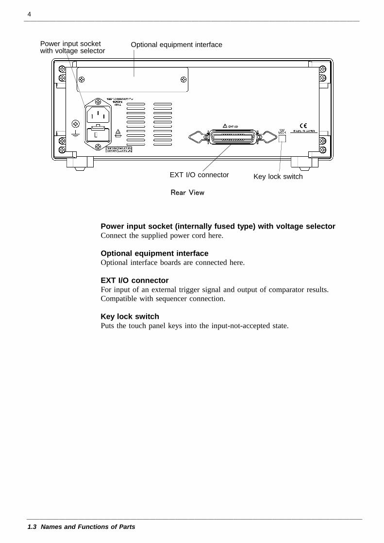
Power input socketwith voltage selector
Optional equipment interface
Key lock switchEXT I/O connector
Rear View
Power input socket (internally fused type) with voltage selectorConnect the supplied power cord here.
Optional equipment interfaceOptional interface boards are connected here.
EXT I/O connectorFor input of an external trigger signal and output of comparator results.Compatible with sequencer connection.
Key lock switchPuts the touch panel keys into the input-not-accepted state.
5
1.3 Names and Functions of Parts
1
2
3
4
5
6
7
8
9
10
11
12
13
14
A
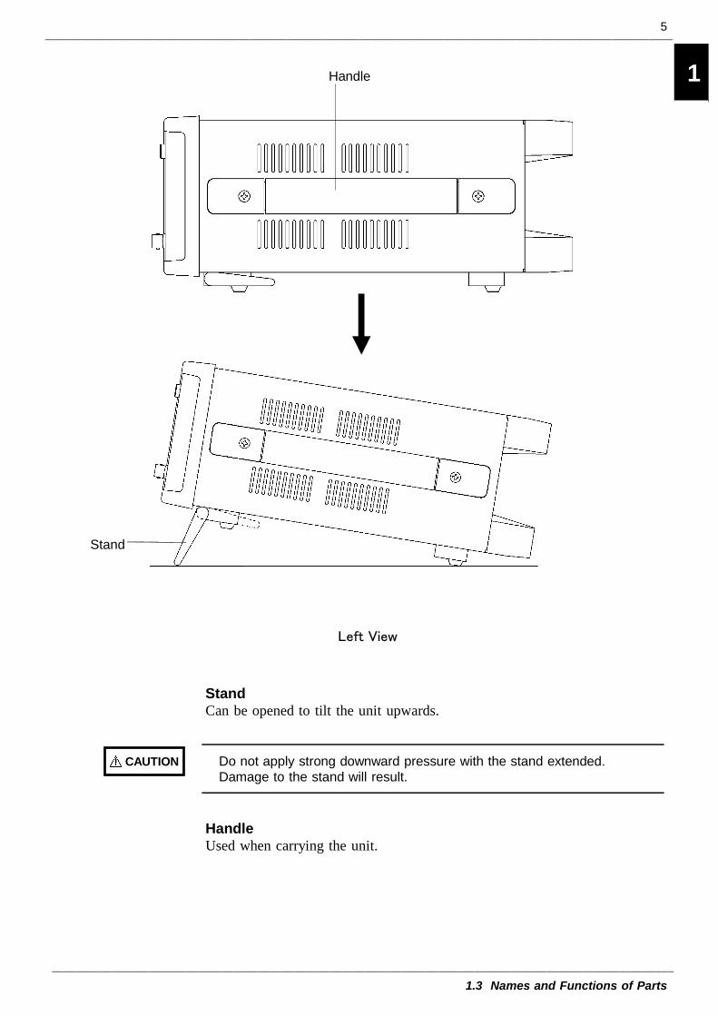
Stand
Handle
Left View
CAUTION Do not apply strong downward pressure with the stand extended.Damage to the stand will result.
StandCan be opened to tilt the unit upwards.
HandleUsed when carrying the unit.

6
1.3 Names and Functions of Parts
7
2.1 Connecting the Power Cord
1
2
3
4
5
6
7
8
9
10
11
12
13
14
A
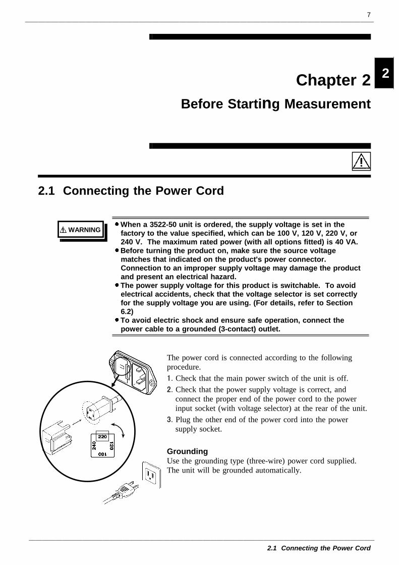
WARNINGWhen a 3522-50 unit is ordered, the supply voltage is set in thefactory to the value specified, which can be 100 V, 120 V, 220 V, or240 V. The maximum rated power (with all options fitted) is 40 VA.Before turning the product on, make sure the source voltagematches that indicated on the product's power connector.Connection to an improper supply voltage may damage the productand present an electrical hazard.The power supply voltage for this product is switchable. To avoidelectrical accidents, check that the voltage selector is set correctlyfor the supply voltage you are using. (For details, refer to Section6.2)To avoid electric shock and ensure safe operation, connect thepower cable to a grounded (3-contact) outlet.
Chapter 2Before Starting Measurement
2.1 Connecting the Power Cord
The power cord is connected according to the followingprocedure.1. Check that the main power switch of the unit is off.2. Check that the power supply voltage is correct, and
connect the proper end of the power cord to the powerinput socket (with voltage selector) at the rear of the unit.
3. Plug the other end of the power cord into the powersupply socket.
GroundingUse the grounding type (three-wire) power cord supplied.The unit will be grounded automatically.
8
2.2 Connecting the Test Leads
2.2.1 Establishing the Connections
CAUTION The maximum voltage which can be applied to the test terminals of the3522-50 unit is 10 V DC (when the 9268 or 9269 is used, 40 V DC). Ifa DC voltage greater than this is applied continuously, the unit may bedamaged. (For how to apply a DC bias voltage, refer to Section 5.7,"Supplying DC Bias")Using a low frequency to measure capacitors with a particular polarity (forexample, electrolytic capacitors) results in a reverse bias being applied. Insome cases this could damage or destroy the capacitor, and therefore aDC bias should always be applied while making the measurements. Alsobe sure that the positive terminal of the capacitor is connected to the HCURterminal on this unit.
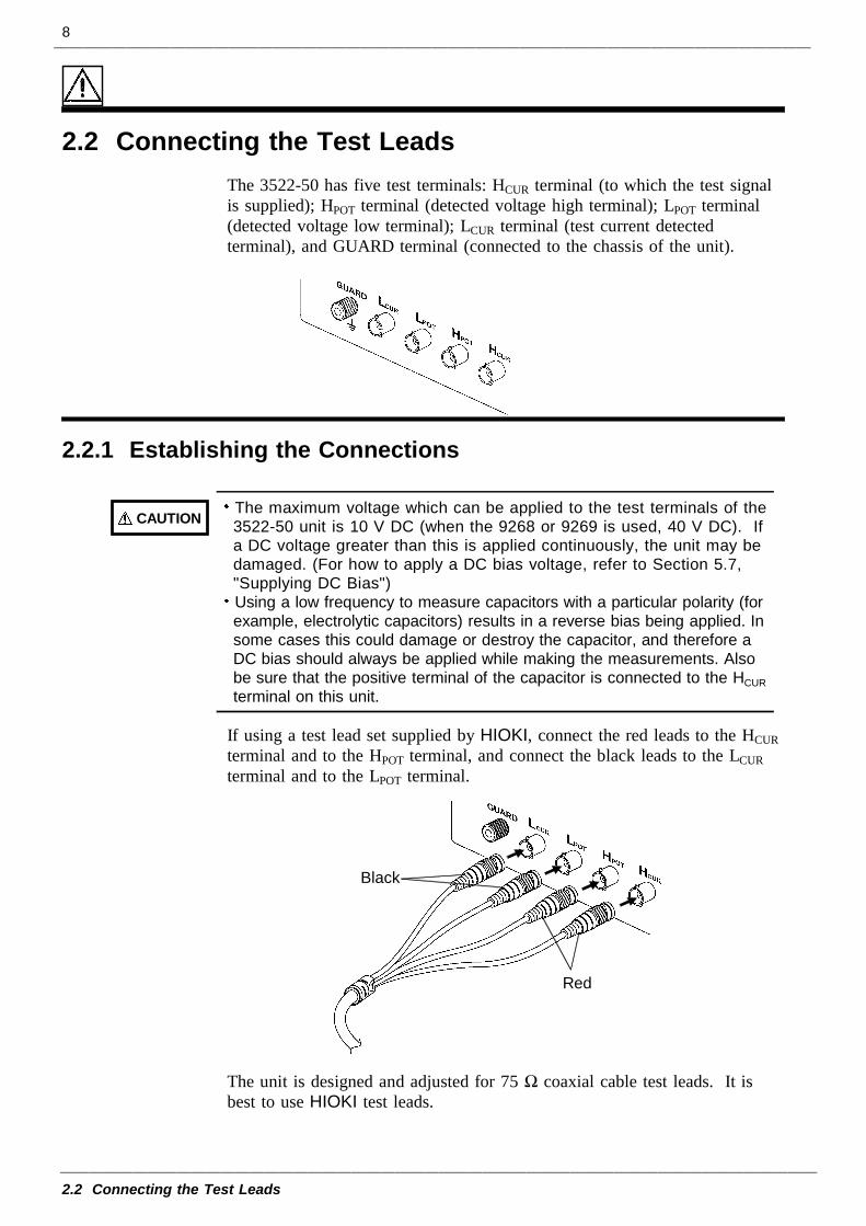
Red
Black
2.2 Connecting the Test LeadsThe 3522-50 has five test terminals: HCUR terminal (to which the test signalis supplied); HPOT terminal (detected voltage high terminal); LPOT terminal(detected voltage low terminal); LCUR terminal (test current detectedterminal), and GUARD terminal (connected to the chassis of the unit).
If using a test lead set supplied by HIOKI, connect the red leads to the HCURterminal and to the HPOT terminal, and connect the black leads to the LCURterminal and to the LPOT terminal.
The unit is designed and adjusted for 75 Ω coaxial cable test leads. It isbest to use HIOKI test leads.
9
2.2 Connecting the Test Leads
1
2
3
4
5
6
7
8
9
10
11
12
13
14
A
NOTE
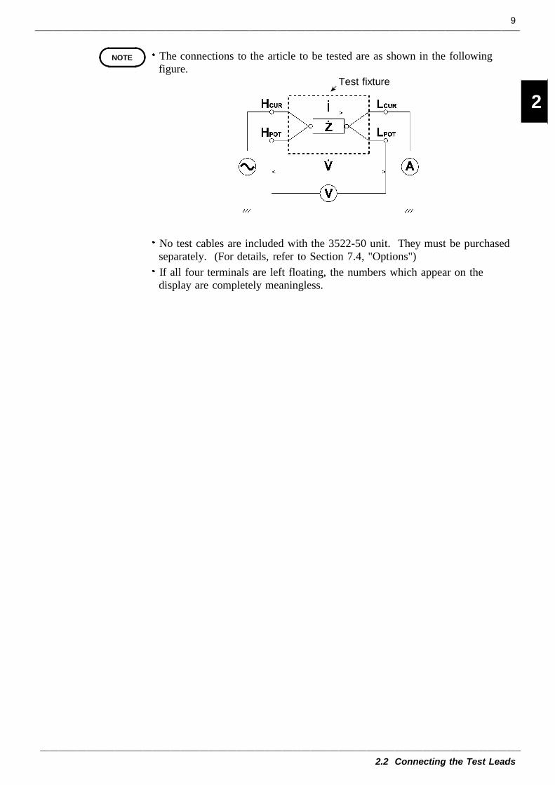
Test fixture
The connections to the article to be tested are as shown in the followingfigure.
No test cables are included with the 3522-50 unit. They must be purchasedseparately. (For details, refer to Section 7.4, "Options")If all four terminals are left floating, the numbers which appear on thedisplay are completely meaningless.
10
2.3 Turning the Power On and Off
Off On
Darker Brighter
NOTE
2.3 Turning the Power On and Off
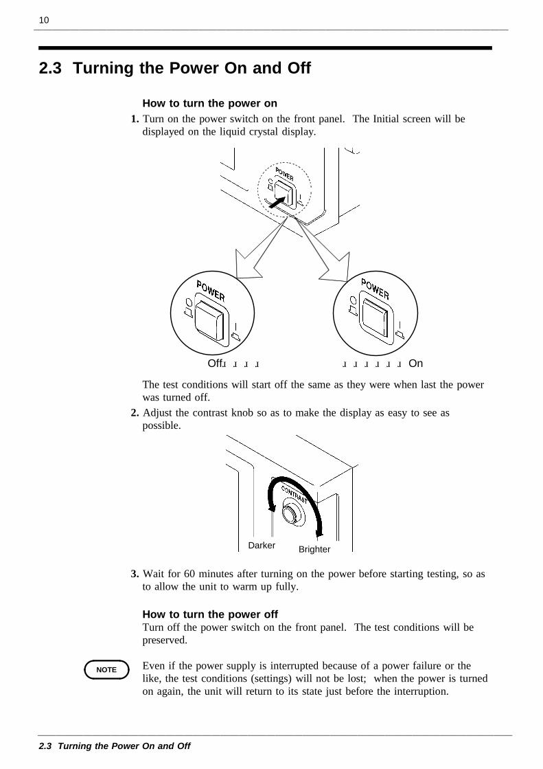
How to turn the power on1. Turn on the power switch on the front panel. The Initial screen will be
displayed on the liquid crystal display.
The test conditions will start off the same as they were when last the powerwas turned off.
2. Adjust the contrast knob so as to make the display as easy to see aspossible.
3. Wait for 60 minutes after turning on the power before starting testing, so asto allow the unit to warm up fully.
How to turn the power offTurn off the power switch on the front panel. The test conditions will bepreserved.
Even if the power supply is interrupted because of a power failure or thelike, the test conditions (settings) will not be lost; when the power is turnedon again, the unit will return to its state just before the interruption.
11
3.1 About the Touch Panel
1
2
3
4
5
6
7
8
9
10
11
12
13
14
A
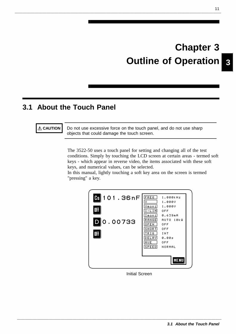
CAUTION Do not use excessive force on the touch panel, and do not use sharpobjects that could damage the touch screen.
Initial Screen
Chapter 3Outline of Operation
3.1 About the Touch Panel
The 3522-50 uses a touch panel for setting and changing all of the testconditions. Simply by touching the LCD screen at certain areas - termed softkeys - which appear in reverse video, the items associated with these softkeys, and numerical values, can be selected.In this manual, lightly touching a soft key area on the screen is termed"pressing" a key.
12
3.2 About the Screen
Initial Screen
Parameterkeys Monitor
display
Menu key
Menu Screen
To change any one of the testconditions (frequency, controlledlevel, etc.), press the correspondingkey on this menu.
3.2 About the Screen
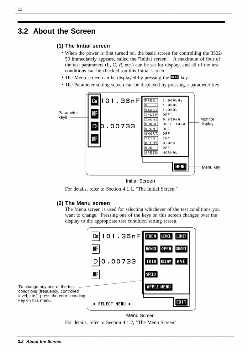
(1) The Initial screenWhen the power is first turned on, the basic screen for controlling the 3522-50 immediately appears, called the "Initial screen". A maximum of four ofthe test parameters (L, C, R, etc.) can be set for display, and all of the testconditions can be checked, on this Initial screen.The Menu screen can be displayed by pressing the key.The Parameter setting screen can be displayed by pressing a parameter key.
For details, refer to Section 4.1.1, "The Initial Screen."
(2) The Menu screenThe Menu screen is used for selecting whichever of the test conditions youwant to change. Pressing one of the keys on this screen changes over thedisplay to the appropriate test condition setting screen.
For details, refer to Section 4.1.2, "The Menu Screen"
13
3.2 About the Screen
1
2
3
4
5
6
7
8
9
10
11
12
13
14
A
Testparameters
Parameter Setting Screen
Test Condition Setting Screen(Test frequency setting screen)
The inactive keys(which cannot currently beoperated) appear as whiterectangles with black characterlegends, i.e. in non-reversed video.
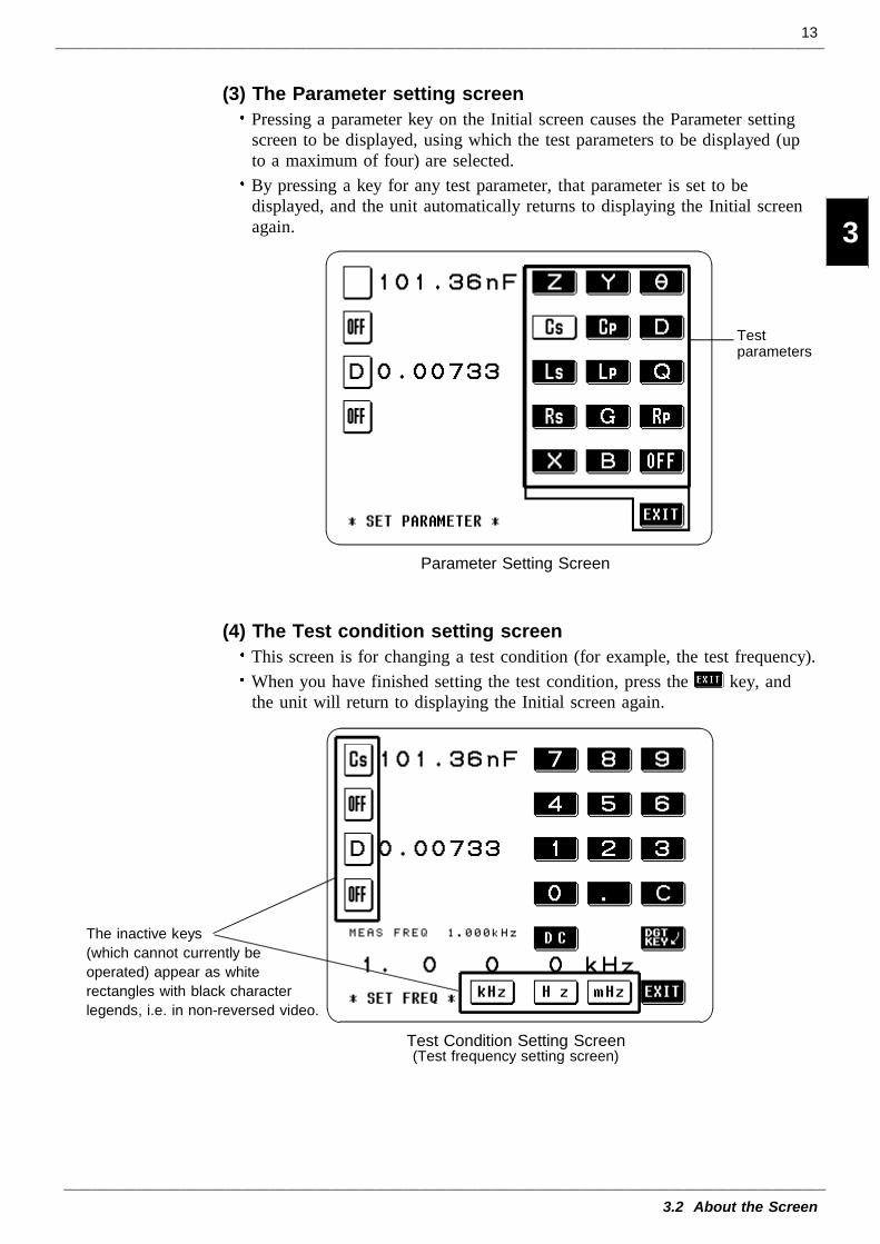
(3) The Parameter setting screenPressing a parameter key on the Initial screen causes the Parameter settingscreen to be displayed, using which the test parameters to be displayed (upto a maximum of four) are selected.By pressing a key for any test parameter, that parameter is set to bedisplayed, and the unit automatically returns to displaying the Initial screenagain.
(4) The Test condition setting screenThis screen is for changing a test condition (for example, the test frequency).When you have finished setting the test condition, press the key, andthe unit will return to displaying the Initial screen again.
14
3.2 About the Screen
3.2.1 Control Screen Sequence
Initial Screen
Menu Screen
Setting Screen
Initial Screen
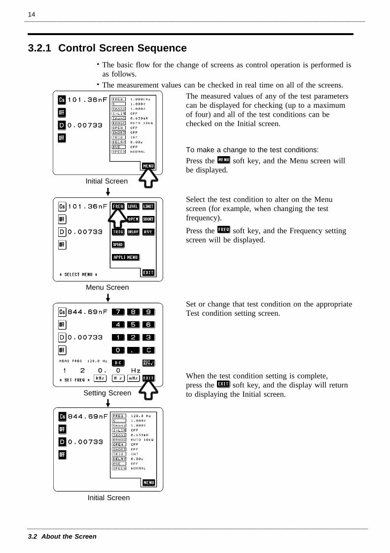
The basic flow for the change of screens as control operation is performed isas follows.The measurement values can be checked in real time on all of the screens.
The measured values of any of the test parameterscan be displayed for checking (up to a maximumof four) and all of the test conditions can bechecked on the Initial screen.
To make a change to the test conditions:Press the soft key, and the Menu screen willbe displayed.
Select the test condition to alter on the Menuscreen (for example, when changing the testfrequency).Press the soft key, and the Frequency settingscreen will be displayed.
Set or change that test condition on the appropriateTest condition setting screen.
When the test condition setting is complete,press the soft key, and the display will returnto displaying the Initial screen.
15
3.3 Basic Measurement
1
2
3
4
5
6
7
8
9
10
11
12
13
14
A
NOTE
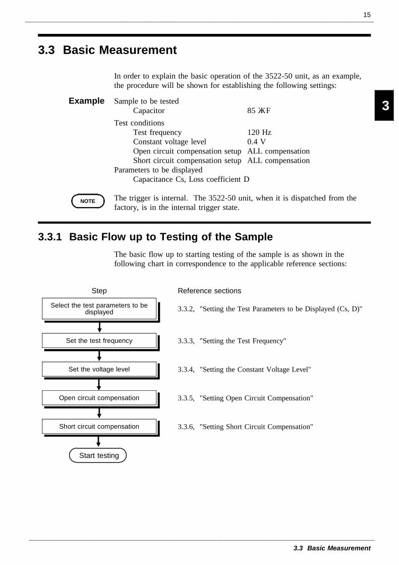
3.3.1 Basic Flow up to Testing of the Sample
Step Reference sections
Select the test parameters to bedisplayed 3.3.2, "Setting the Test Parameters to be Displayed (Cs, D)"
Set the test frequency 3.3.3, "Setting the Test Frequency"
Set the voltage level 3.3.4, "Setting the Constant Voltage Level"
Open circuit compensation 3.3.5, "Setting Open Circuit Compensation"
Short circuit compensation 3.3.6, "Setting Short Circuit Compensation"
Start testing
3.3 Basic Measurement
In order to explain the basic operation of the 3522-50 unit, as an example,the procedure will be shown for establishing the following settings:
Example Sample to be testedCapacitor 85 μF
Test conditionsTest frequency 120 HzConstant voltage level 0.4 VOpen circuit compensation setup ALL compensationShort circuit compensation setup ALL compensation
Parameters to be displayedCapacitance Cs, Loss coefficient D
The trigger is internal. The 3522-50 unit, when it is dispatched from thefactory, is in the internal trigger state.
The basic flow up to starting testing of the sample is as shown in thefollowing chart in correspondence to the applicable reference sections:
16
3.3 Basic Measurement
3.3.2 Setting the Test Parameters to be Displayed (Cs, D)
Before Setting After Setting
Initial Screen
Parameter Setting Screen
NOTE
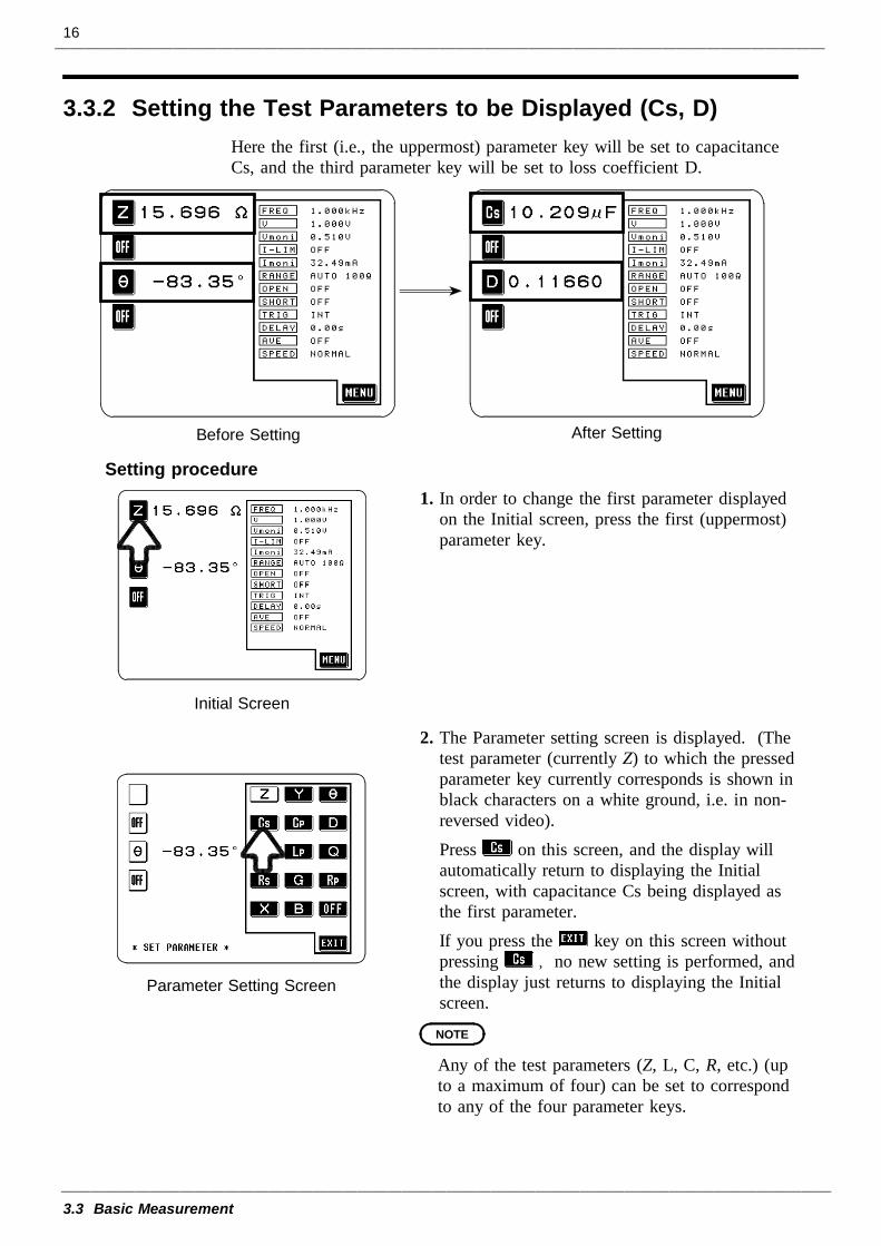
Here the first (i.e., the uppermost) parameter key will be set to capacitanceCs, and the third parameter key will be set to loss coefficient D.
Setting procedure1. In order to change the first parameter displayed
on the Initial screen, press the first (uppermost)parameter key.
2. The Parameter setting screen is displayed. (Thetest parameter (currently Z) to which the pressedparameter key currently corresponds is shown inblack characters on a white ground, i.e. in non-reversed video).Press on this screen, and the display willautomatically return to displaying the Initialscreen, with capacitance Cs being displayed asthe first parameter.If you press the key on this screen withoutpressing , no new setting is performed, andthe display just returns to displaying the Initialscreen.
Any of the test parameters (Z, L, C, R, etc.) (upto a maximum of four) can be set to correspondto any of the four parameter keys.
17
3.3 Basic Measurement
1
2
3
4
5
6
7
8
9
10
11
12
13
14
A
Initial Screen
Parameter Setting Screen
NOTE
Initial Screen
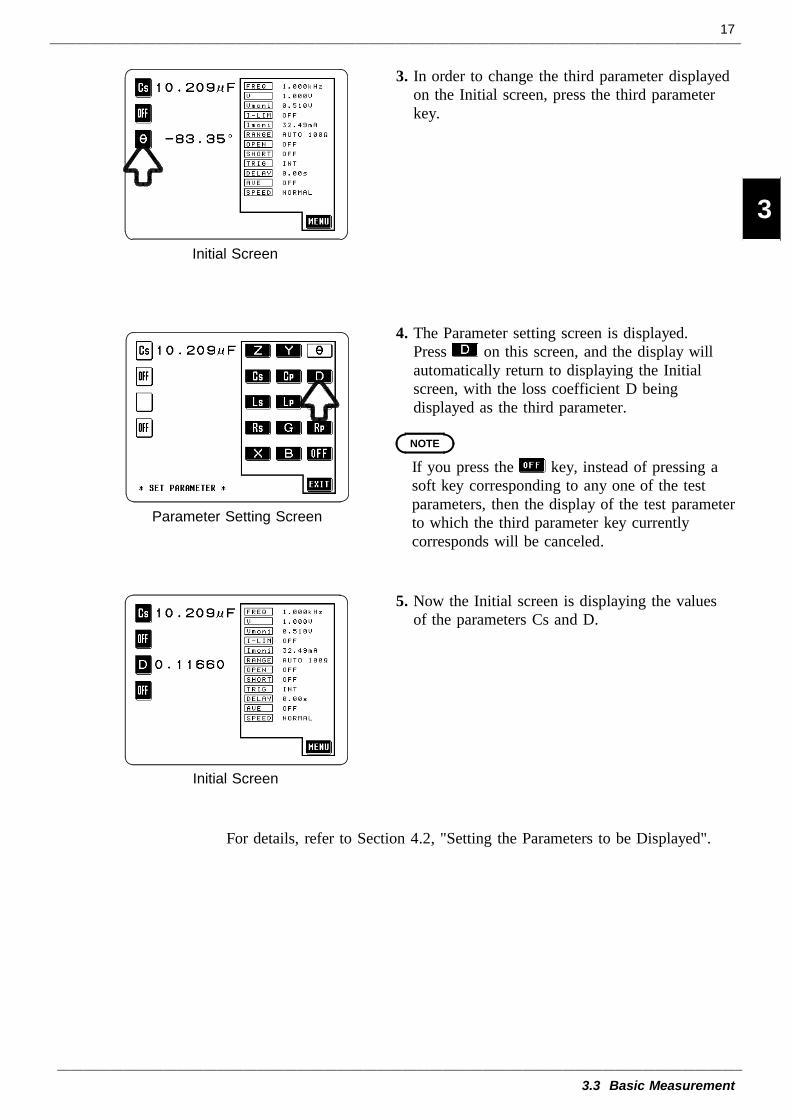
3. In order to change the third parameter displayedon the Initial screen, press the third parameterkey.
4. The Parameter setting screen is displayed.Press on this screen, and the display willautomatically return to displaying the Initialscreen, with the loss coefficient D beingdisplayed as the third parameter.
If you press the key, instead of pressing asoft key corresponding to any one of the testparameters, then the display of the test parameterto which the third parameter key currentlycorresponds will be canceled.
5. Now the Initial screen is displaying the valuesof the parameters Cs and D.
For details, refer to Section 4.2, "Setting the Parameters to be Displayed".
18
3.3 Basic Measurement
3.3.3 Setting the Test Frequency
Before Setting After Setting
Initial Screen
Menu Screen
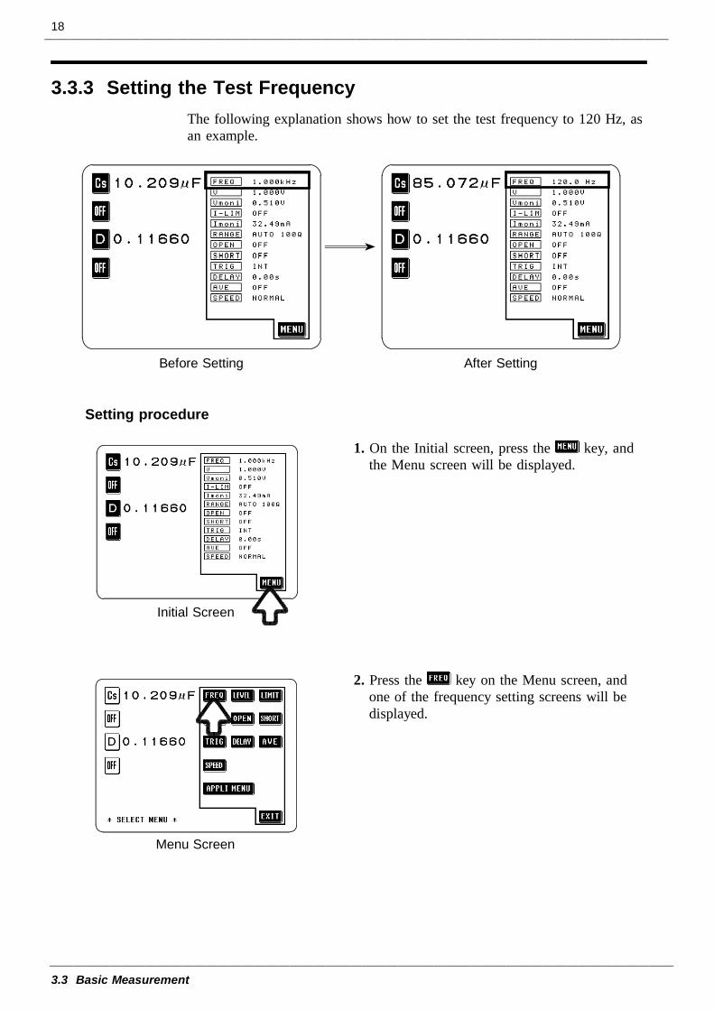
The following explanation shows how to set the test frequency to 120 Hz, asan example.
Setting procedure
1. On the Initial screen, press the key, andthe Menu screen will be displayed.
2. Press the key on the Menu screen, andone of the frequency setting screens will bedisplayed.
19
3.3 Basic Measurement
Digit Screen Ten Key Screen
Ten Key Screen
Digit Screen
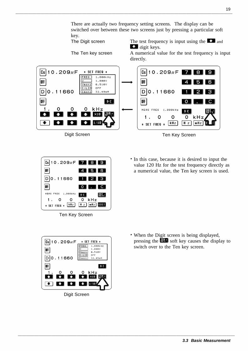
There are actually two frequency setting screens. The display can beswitched over between these two screens just by pressing a particular softkey.The Digit screen The test frequency is input using the and
digit keys.The Ten key screen A numerical value for the test frequency is input
directly.
In this case, because it is desired to input thevalue 120 Hz for the test frequency directly asa numerical value, the Ten key screen is used.
When the Digit screen is being displayed,pressing the soft key causes the display toswitch over to the Ten key screen.
20
3.3 Basic Measurement
Ten Key Screen
Ten Key Screen
Initial Screen
NOTE
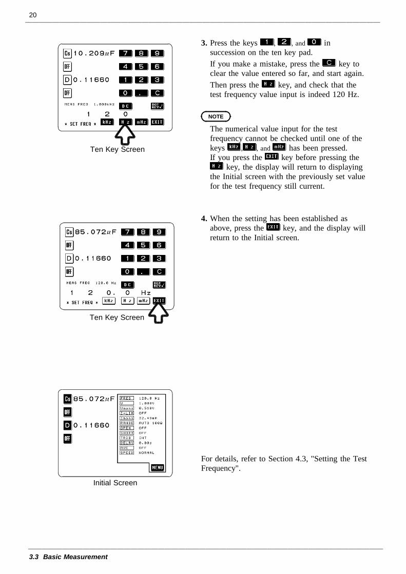
3. Press the keys , , and insuccession on the ten key pad.If you make a mistake, press the key toclear the value entered so far, and start again.Then press the key, and check that thetest frequency value input is indeed 120 Hz.
The numerical value input for the testfrequency cannot be checked until one of thekeys , , and has been pressed.If you press the key before pressing the
key, the display will return to displayingthe Initial screen with the previously set valuefor the test frequency still current.
4. When the setting has been established asabove, press the key, and the display willreturn to the Initial screen.
For details, refer to Section 4.3, "Setting the TestFrequency".
21
3.3 Basic Measurement
3.3.4 Setting the Constant Voltage Level
Before Setting After Setting
Initial Screen
Menu Screen
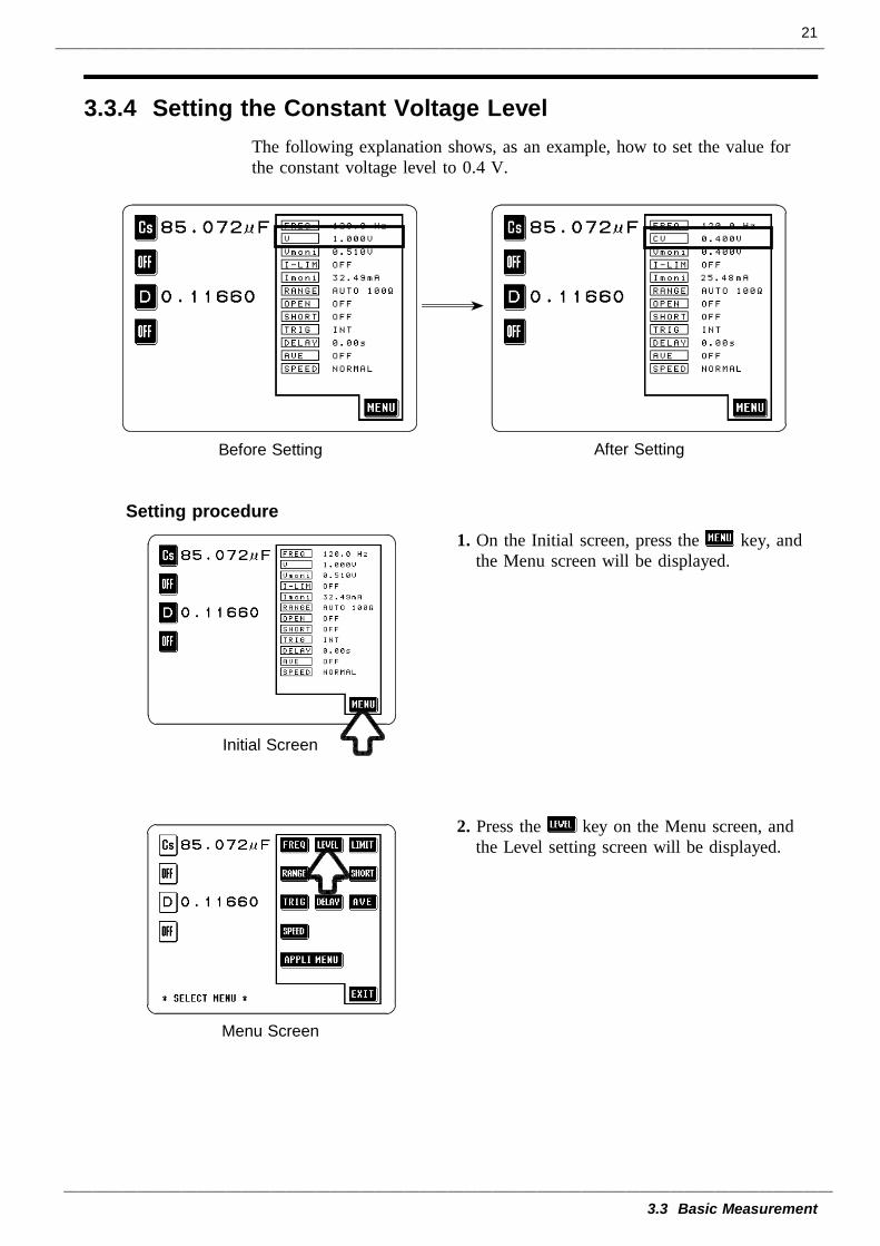
The following explanation shows, as an example, how to set the value forthe constant voltage level to 0.4 V.
Setting procedure1. On the Initial screen, press the key, and
the Menu screen will be displayed.
2. Press the key on the Menu screen, andthe Level setting screen will be displayed.
22
3.3 Basic Measurement
Level Setting Screen
Level Setting Screen
Level Setting Screen
NOTE
Initial Screen
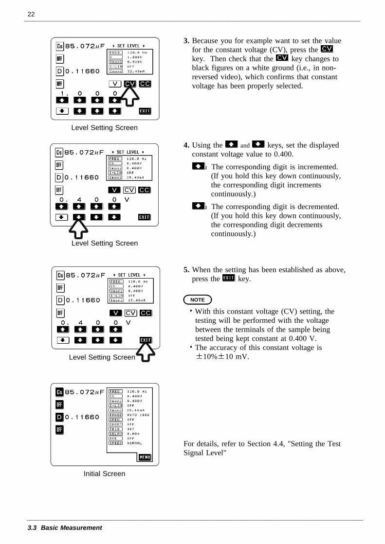
3. Because you for example want to set the valuefor the constant voltage (CV), press thekey. Then check that the key changes toblack figures on a white ground (i.e., in non-reversed video), which confirms that constantvoltage has been properly selected.
4. Using the and keys, set the displayedconstant voltage value to 0.400.
The corresponding digit is incremented.(If you hold this key down continuously,the corresponding digit incrementscontinuously.)
The corresponding digit is decremented.(If you hold this key down continuously,the corresponding digit decrementscontinuously.)
5. When the setting has been established as above,press the key.
With this constant voltage (CV) setting, thetesting will be performed with the voltagebetween the terminals of the sample beingtested being kept constant at 0.400 V.The accuracy of this constant voltage is
10% 10 mV.
For details, refer to Section 4.4, "Setting the TestSignal Level"
23
3.3 Basic Measurement
3.3.5 Setting Open Circuit Compensation
Before Setting After Setting
Initial Screen
Menu Screen
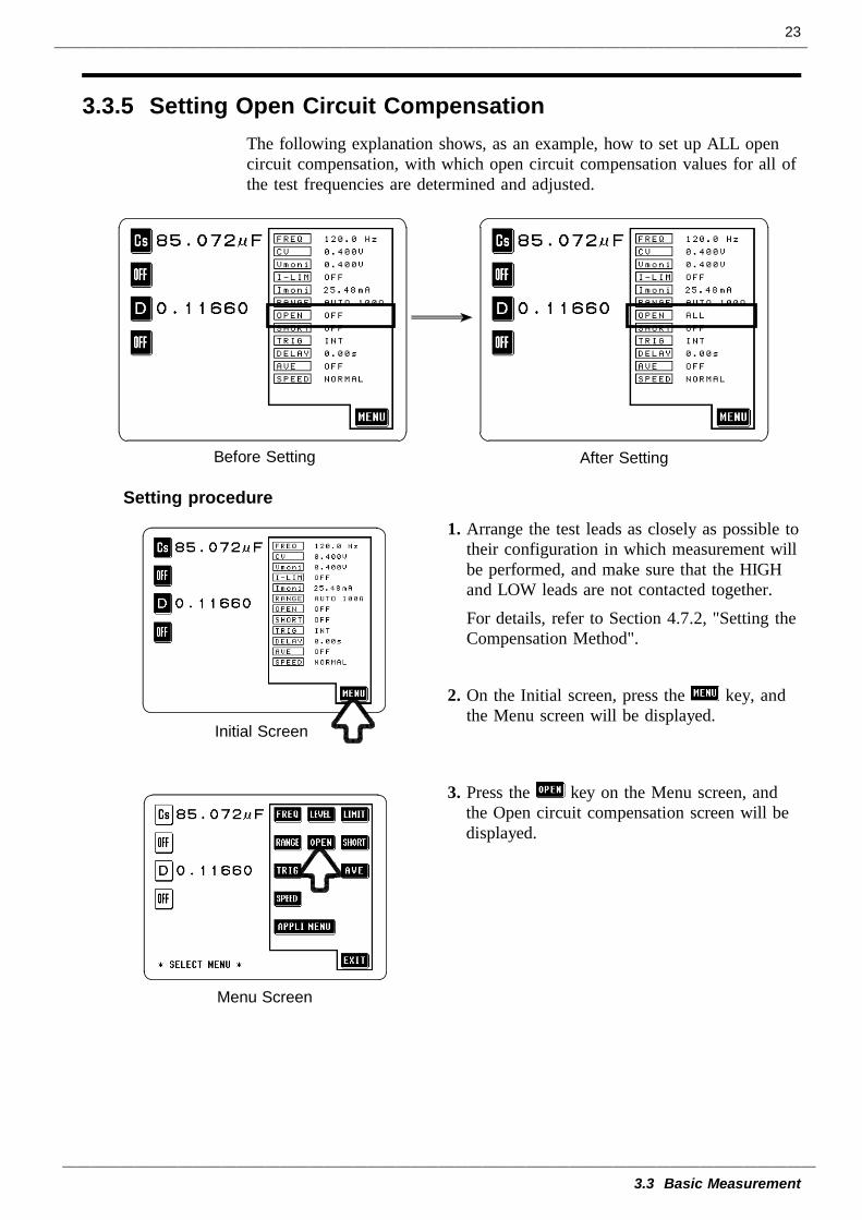
The following explanation shows, as an example, how to set up ALL opencircuit compensation, with which open circuit compensation values for all ofthe test frequencies are determined and adjusted.
Setting procedure
1. Arrange the test leads as closely as possible totheir configuration in which measurement willbe performed, and make sure that the HIGHand LOW leads are not contacted together.For details, refer to Section 4.7.2, "Setting theCompensation Method".
2. On the Initial screen, press the key, andthe Menu screen will be displayed.
3. Press the key on the Menu screen, andthe Open circuit compensation screen will bedisplayed.
24
3.3 Basic Measurement
Open Circuit Compensation Screen
Confirmation Screen
NOTE
Data Determination Screen
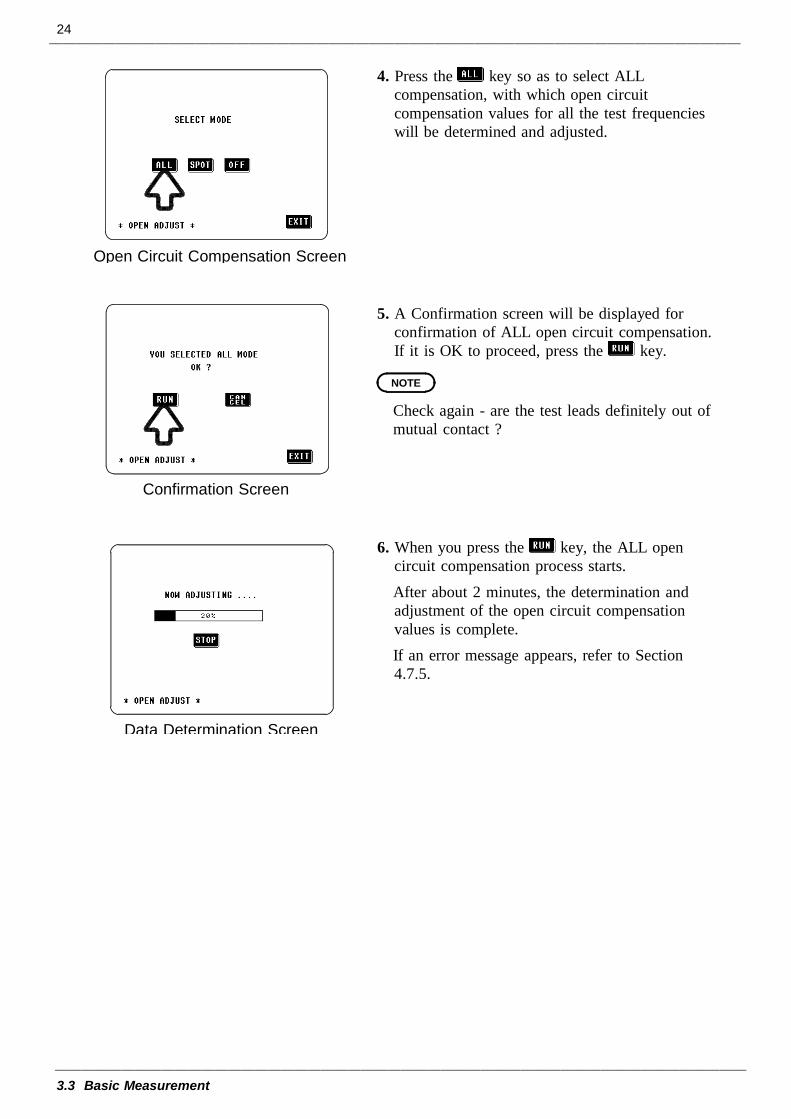
4. Press the key so as to select ALLcompensation, with which open circuitcompensation values for all the test frequencieswill be determined and adjusted.
5. A Confirmation screen will be displayed forconfirmation of ALL open circuit compensation.If it is OK to proceed, press the key.
Check again - are the test leads definitely out ofmutual contact ?
6. When you press the key, the ALL opencircuit compensation process starts.After about 2 minutes, the determination andadjustment of the open circuit compensationvalues is complete.If an error message appears, refer to Section4.7.5.
25
3.3 Basic Measurement
Confirmation Screen
Initial Screen
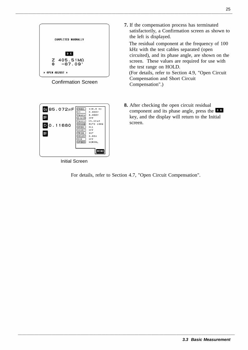
7. If the compensation process has terminatedsatisfactorily, a Confirmation screen as shown tothe left is displayed.The residual component at the frequency of 100kHz with the test cables separated (opencircuited), and its phase angle, are shown on thescreen. These values are required for use withthe test range on HOLD.(For details, refer to Section 4.9, "Open CircuitCompensation and Short CircuitCompensation".)
8. After checking the open circuit residualcomponent and its phase angle, press thekey, and the display will return to the Initialscreen.
For details, refer to Section 4.7, "Open Circuit Compensation".
26
3.3 Basic Measurement
3.3.6 Setting Short Circuit Compensation
Before Setting After Setting
Initial Screen
Menu Screen
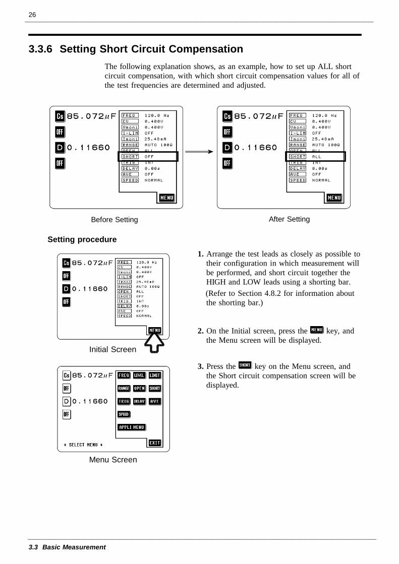
The following explanation shows, as an example, how to set up ALL shortcircuit compensation, with which short circuit compensation values for all ofthe test frequencies are determined and adjusted.
Setting procedure
1. Arrange the test leads as closely as possible totheir configuration in which measurement willbe performed, and short circuit together theHIGH and LOW leads using a shorting bar.(Refer to Section 4.8.2 for information aboutthe shorting bar.)
2. On the Initial screen, press the key, andthe Menu screen will be displayed.
3. Press the key on the Menu screen, andthe Short circuit compensation screen will bedisplayed.
27
3.3 Basic Measurement
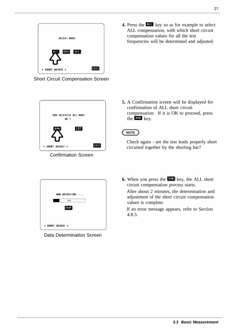
Short Circuit Compensation Screen
Confirmation Screen
NOTE
Data Determination Screen
4. Press the key so as for example to selectALL compensation, with which short circuitcompensation values for all the testfrequencies will be determined and adjusted.
5. A Confirmation screen will be displayed forconfirmation of ALL short circuitcompensation. If it is OK to proceed, pressthe key.
Check again - are the test leads properly shortcircuited together by the shorting bar?
6. When you press the key, the ALL shortcircuit compensation process starts.After about 2 minutes, the determination andadjustment of the short circuit compensationvalues is complete.If an error message appears, refer to Section4.8.5.
28
3.3 Basic Measurement
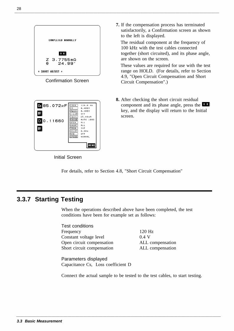
Confirmation Screen
Initial Screen
3.3.7 Starting Testing
7. If the compensation process has terminatedsatisfactorily, a Confirmation screen as shownto the left is displayed.The residual component at the frequency of100 kHz with the test cables connectedtogether (short circuited), and its phase angle,are shown on the screen.These values are required for use with the testrange on HOLD. (For details, refer to Section4.9, "Open Circuit Compensation and ShortCircuit Compensation".)
8. After checking the short circuit residualcomponent and its phase angle, press thekey, and the display will return to the Initialscreen.
For details, refer to Section 4.8, "Short Circuit Compensation"
When the operations described above have been completed, the testconditions have been for example set as follows:
Test conditionsFrequency 120 HzConstant voltage level 0.4 VOpen circuit compensation ALL compensationShort circuit compensation ALL compensation
Parameters displayedCapacitance Cs, Loss coefficient D
Connect the actual sample to be tested to the test cables, to start testing.
29
4.1 Description of the Screens
1
2
3
4
5
6
7
8
9
10
11
12
13
14
A
Chapter 4Detailed Description of
Functions
4.1 Description of the Screens
The Initial screen, Menu screen, Application menu screen will be explained.
30
4.1 Description of the Screens
4.1.1 The Initial Screen
2 134567891011121314
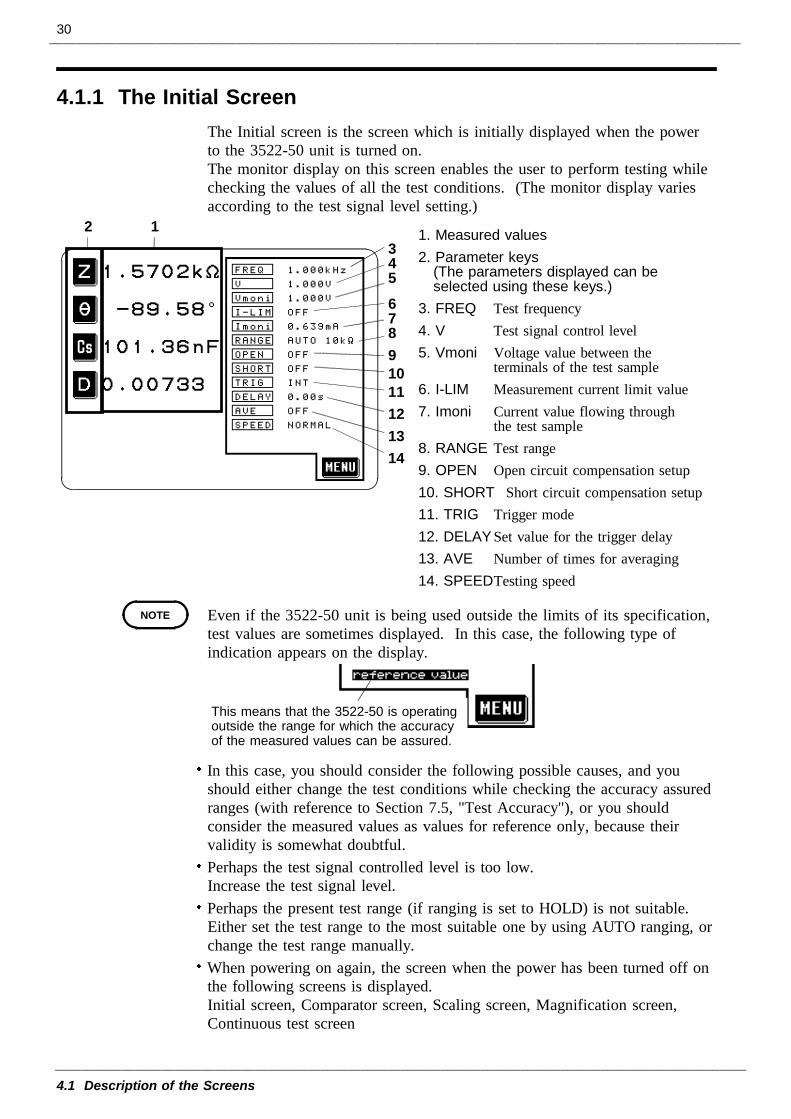
1. Measured values2. Parameter keys
(The parameters displayed can beselected using these keys.)
3. FREQ Test frequency4. V Test signal control level5. Vmoni Voltage value between the
terminals of the test sample6. I-LIM Measurement current limit value7. Imoni Current value flowing through
the test sample8. RANGE Test range9. OPEN Open circuit compensation setup10. SHORT Short circuit compensation setup11. TRIG Trigger mode12. DELAY Set value for the trigger delay13. AVE Number of times for averaging14. SPEED Testing speed
NOTE
This means that the 3522-50 is operatingoutside the range for which the accuracyof the measured values can be assured.
The Initial screen is the screen which is initially displayed when the powerto the 3522-50 unit is turned on.The monitor display on this screen enables the user to perform testing whilechecking the values of all the test conditions. (The monitor display variesaccording to the test signal level setting.)
Even if the 3522-50 unit is being used outside the limits of its specification,test values are sometimes displayed. In this case, the following type ofindication appears on the display.
In this case, you should consider the following possible causes, and youshould either change the test conditions while checking the accuracy assuredranges (with reference to Section 7.5, "Test Accuracy"), or you shouldconsider the measured values as values for reference only, because theirvalidity is somewhat doubtful.Perhaps the test signal controlled level is too low.Increase the test signal level.Perhaps the present test range (if ranging is set to HOLD) is not suitable.Either set the test range to the most suitable one by using AUTO ranging, orchange the test range manually.When powering on again, the screen when the power has been turned off onthe following screens is displayed.Initial screen, Comparator screen, Scaling screen, Magnification screen,Continuous test screen
31
4.1 Description of the Screens
1
2
3
4
5
6
7
8
9
10
11
12
13
14
A
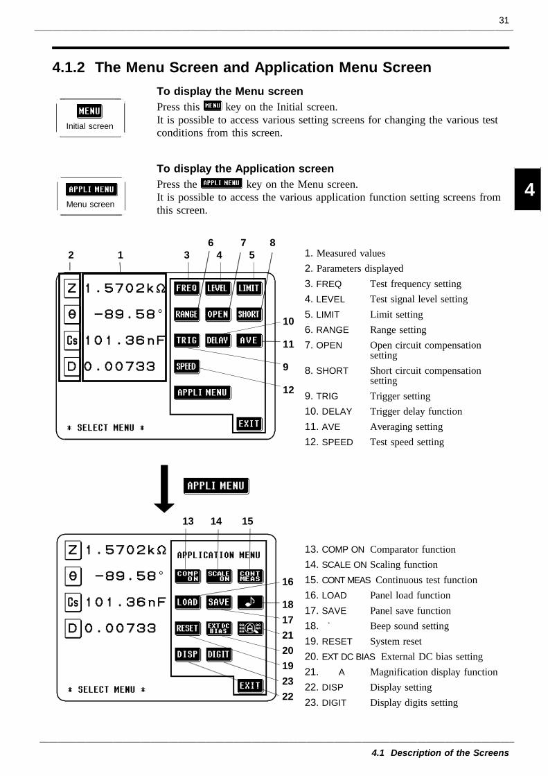
4.1.2 The Menu Screen and Application Menu Screen
Initial screen
Menu screen
1. Measured values2. Parameters displayed3. FREQ Test frequency setting4. LEVEL Test signal level setting5. LIMIT Limit setting6. RANGE Range setting7. OPEN Open circuit compensation
setting8. SHORT Short circuit compensation
setting9. TRIG Trigger setting10. DELAY Trigger delay function11. AVE Averaging setting12. SPEED Test speed setting
13. COMP ON Comparator function14. SCALE ON Scaling function15. CONT MEAS Continuous test function16. LOAD Panel load function17. SAVE Panel save function18. Beep sound setting19. RESET System reset20. EXT DC BIAS External DC bias setting21. A Magnification display function22. DISP Display setting23. DIGIT Display digits setting
2 1 3 4 56 7 8
10
11
9
12
13 14 15
16
18172120192322
To display the Menu screenPress this key on the Initial screen.It is possible to access various setting screens for changing the various testconditions from this screen.
To display the Application screenPress the key on the Menu screen.It is possible to access the various application function setting screens fromthis screen.
32
4.2 Setting the Parameters to be Displayed
4.2.1 Control Screen Sequence
Initial screen
Parameter setting screen
Initial screen
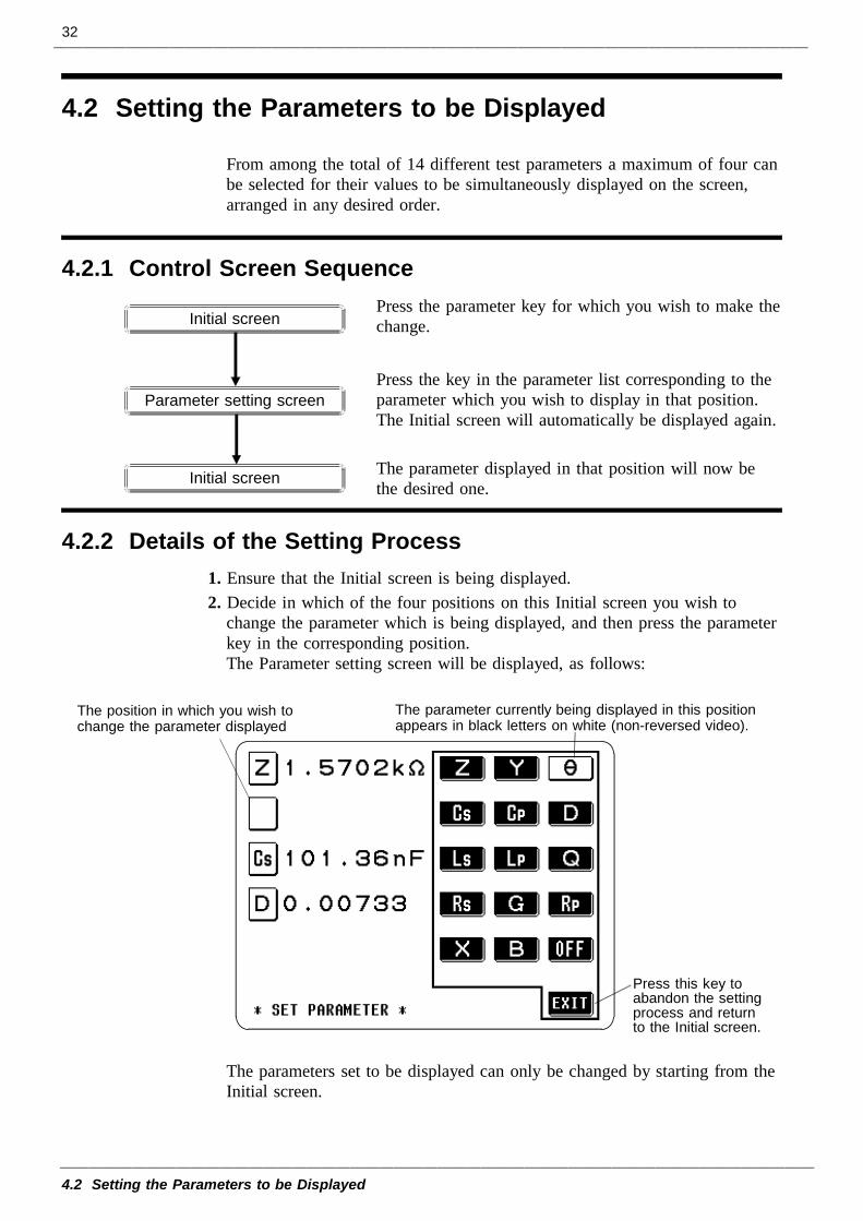
4.2.2 Details of the Setting Process
The position in which you wish tochange the parameter displayed
The parameter currently being displayed in this positionappears in black letters on white (non-reversed video).
Press this key toabandon the settingprocess and returnto the Initial screen.
4.2 Setting the Parameters to be Displayed
From among the total of 14 different test parameters a maximum of four canbe selected for their values to be simultaneously displayed on the screen,arranged in any desired order.
Press the parameter key for which you wish to make thechange.
Press the key in the parameter list corresponding to theparameter which you wish to display in that position.The Initial screen will automatically be displayed again.
The parameter displayed in that position will now bethe desired one.
1. Ensure that the Initial screen is being displayed.2. Decide in which of the four positions on this Initial screen you wish to
change the parameter which is being displayed, and then press the parameterkey in the corresponding position.The Parameter setting screen will be displayed, as follows:
The parameters set to be displayed can only be changed by starting from theInitial screen.
33
4.2 Setting the Parameters to be Displayed
1
2
3
4
5
6
7
8
9
10
11
12
13
14
A
NOTE
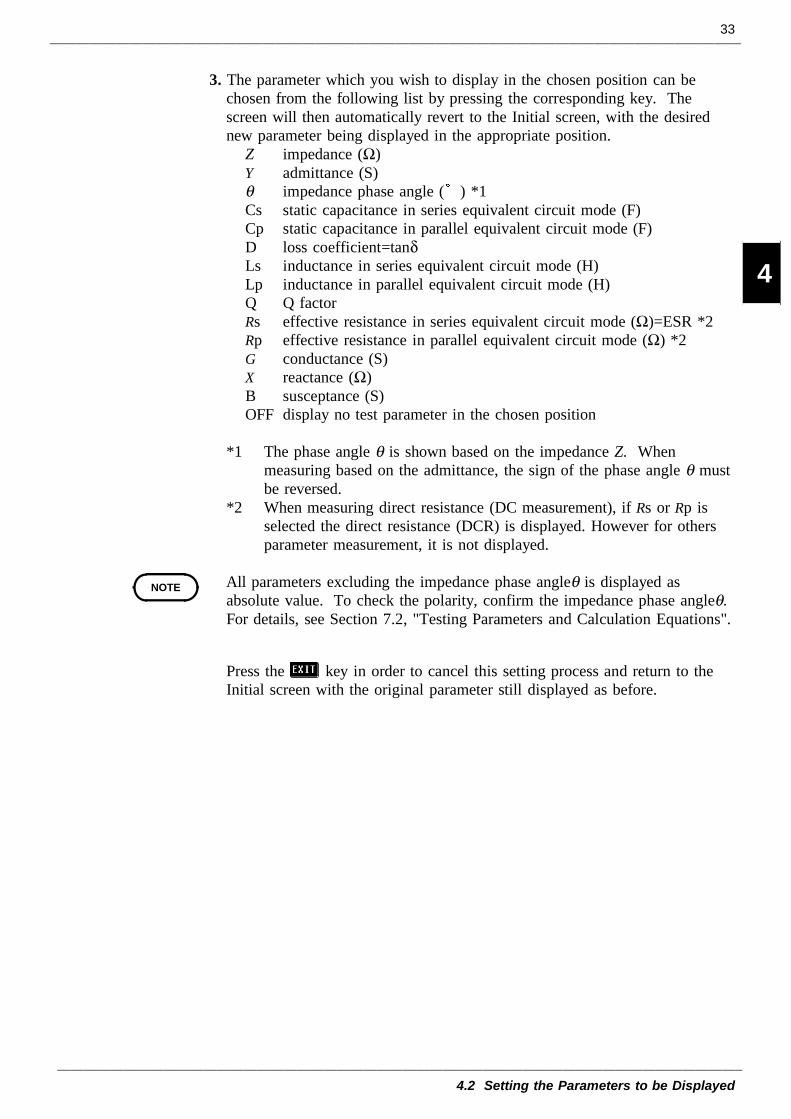
3. The parameter which you wish to display in the chosen position can bechosen from the following list by pressing the corresponding key. Thescreen will then automatically revert to the Initial screen, with the desirednew parameter being displayed in the appropriate position.
Z impedance (Ω)Y admittance (S)θ impedance phase angle ( ) *1Cs static capacitance in series equivalent circuit mode (F)Cp static capacitance in parallel equivalent circuit mode (F)D loss coefficient=tanδLs inductance in series equivalent circuit mode (H)Lp inductance in parallel equivalent circuit mode (H)Q Q factorRs effective resistance in series equivalent circuit mode (Ω)=ESR *2Rp effective resistance in parallel equivalent circuit mode (Ω) *2G conductance (S)X reactance (Ω)B susceptance (S)OFF display no test parameter in the chosen position
*1 The phase angle θ is shown based on the impedance Z. Whenmeasuring based on the admittance, the sign of the phase angle θ mustbe reversed.
*2 When measuring direct resistance (DC measurement), if Rs or Rp isselected the direct resistance (DCR) is displayed. However for othersparameter measurement, it is not displayed.
All parameters excluding the impedance phase angleθ is displayed asabsolute value. To check the polarity, confirm the impedance phase angleθ.For details, see Section 7.2, "Testing Parameters and Calculation Equations".
Press the key in order to cancel this setting process and return to theInitial screen with the original parameter still displayed as before.
34
4.2 Setting the Parameters to be Displayed
4.2.3 Series Equivalent Circuit Mode and Parallel EquivalentCircuit Mode
Series equivalentcircuit mode
Parallel equivalentcircuit mode
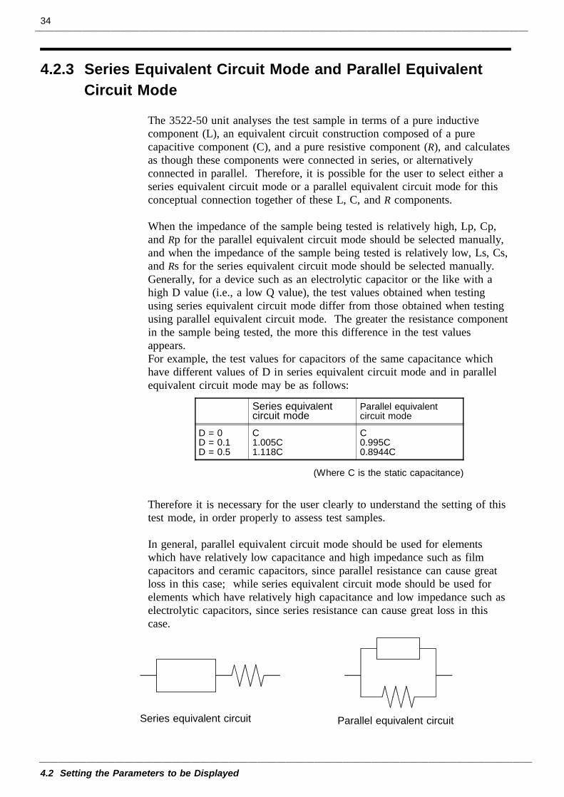
D = 0D = 0.1D = 0.5
C1.005C1.118C
C0.995C0.8944C
(Where C is the static capacitance)
Series equivalent circuit Parallel equivalent circuit
The 3522-50 unit analyses the test sample in terms of a pure inductivecomponent (L), an equivalent circuit construction composed of a purecapacitive component (C), and a pure resistive component (R), and calculatesas though these components were connected in series, or alternativelyconnected in parallel. Therefore, it is possible for the user to select either aseries equivalent circuit mode or a parallel equivalent circuit mode for thisconceptual connection together of these L, C, and R components.
When the impedance of the sample being tested is relatively high, Lp, Cp,and Rp for the parallel equivalent circuit mode should be selected manually,and when the impedance of the sample being tested is relatively low, Ls, Cs,and Rs for the series equivalent circuit mode should be selected manually.Generally, for a device such as an electrolytic capacitor or the like with ahigh D value (i.e., a low Q value), the test values obtained when testingusing series equivalent circuit mode differ from those obtained when testingusing parallel equivalent circuit mode. The greater the resistance componentin the sample being tested, the more this difference in the test valuesappears.For example, the test values for capacitors of the same capacitance whichhave different values of D in series equivalent circuit mode and in parallelequivalent circuit mode may be as follows:
Therefore it is necessary for the user clearly to understand the setting of thistest mode, in order properly to assess test samples.
In general, parallel equivalent circuit mode should be used for elementswhich have relatively low capacitance and high impedance such as filmcapacitors and ceramic capacitors, since parallel resistance can cause greatloss in this case; while series equivalent circuit mode should be used forelements which have relatively high capacitance and low impedance such aselectrolytic capacitors, since series resistance can cause great loss in thiscase.
35
4.3 Setting the Test Frequency
4.3.1 Control Screen Sequence
Input using thenumeric keypad
Input using thedigit keys
Initial screen
Menu screen
Frequency setting screen
Digit screenTen key screen
Initial screen
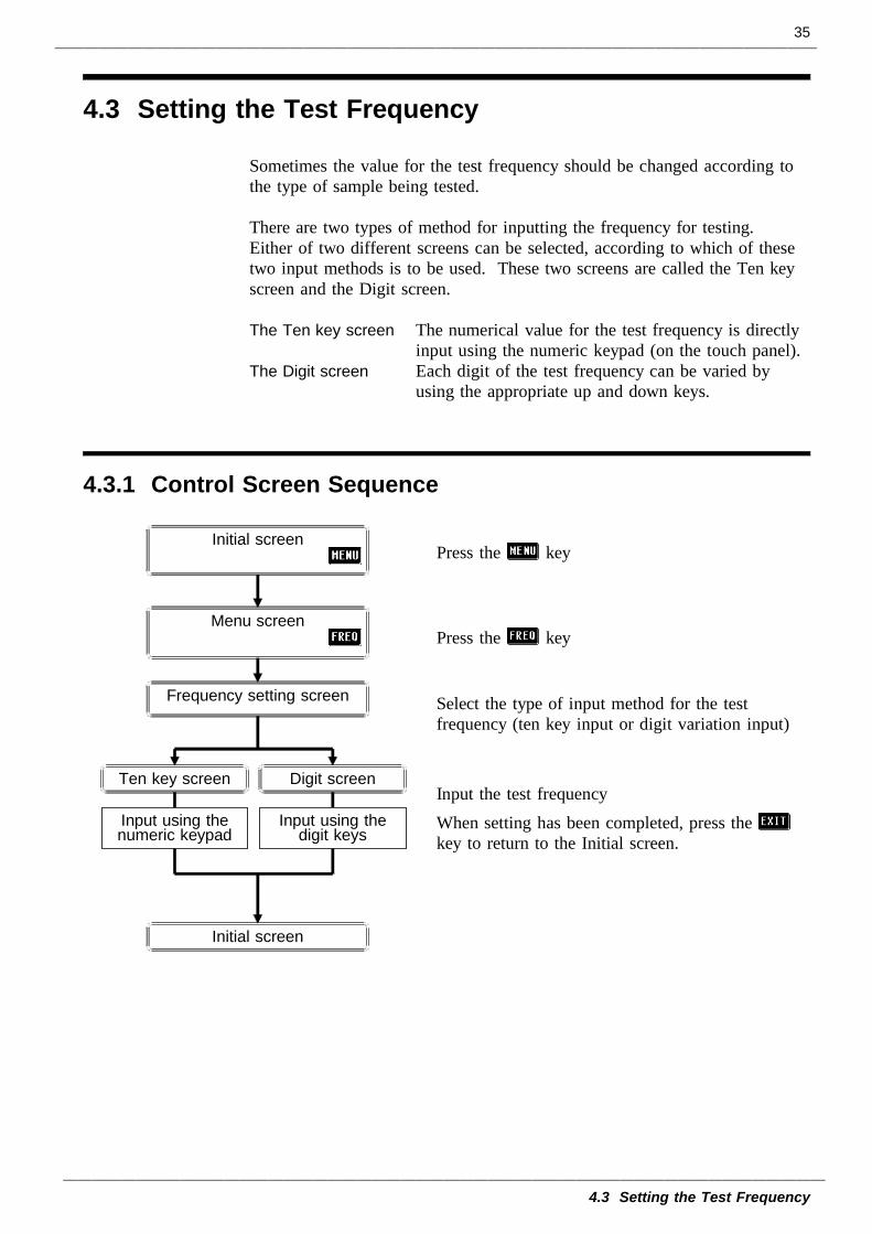
4.3 Setting the Test Frequency
Sometimes the value for the test frequency should be changed according tothe type of sample being tested.
There are two types of method for inputting the frequency for testing.Either of two different screens can be selected, according to which of thesetwo input methods is to be used. These two screens are called the Ten keyscreen and the Digit screen.
The Ten key screen The numerical value for the test frequency is directlyinput using the numeric keypad (on the touch panel).
The Digit screen Each digit of the test frequency can be varied byusing the appropriate up and down keys.
Press the key
Press the key
Select the type of input method for the testfrequency (ten key input or digit variation input)
Input the test frequencyWhen setting has been completed, press thekey to return to the Initial screen.
36
4.3 Setting the Test Frequency
4.3.2 Selecting the Input Method
Changes to the Ten key screenTen Key ScreenDigit Screen
Changes to the Digit screen
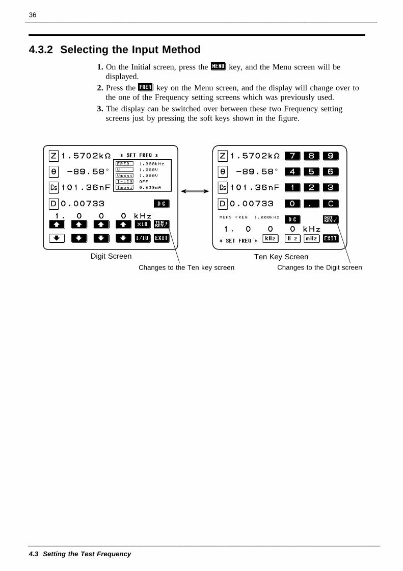
1. On the Initial screen, press the key, and the Menu screen will bedisplayed.
2. Press the key on the Menu screen, and the display will change over tothe one of the Frequency setting screens which was previously used.
3. The display can be switched over between these two Frequency settingscreens just by pressing the soft keys shown in the figure.
37
4.3 Setting the Test Frequency
4.3.3 Input Using the Ten Key Screen
Shows the currently settest frequency
Shows the testfrequency input so far
Returns to the Initial screenUnits keys (shown in non-reversed video, untilthe numerical value for the frequency has been input)
Numeric keypad
NOTE
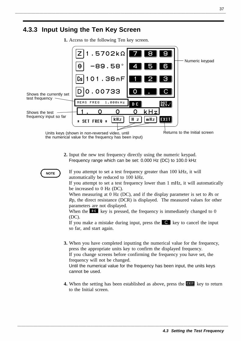
1. Access to the following Ten key screen.
2. Input the new test frequency directly using the numeric keypad.Frequency range which can be set: 0.000 Hz (DC) to 100.0 kHz
If you attempt to set a test frequency greater than 100 kHz, it willautomatically be reduced to 100 kHz.If you attempt to set a test frequency lower than 1 mHz, it will automaticallybe increased to 0 Hz (DC).When measuring at 0 Hz (DC), and if the display parameter is set to Rs orRp, the direct resistance (DCR) is displayed. The measured values for otherparameters are not displayed.When the key is pressed, the frequency is immediately changed to 0(DC).If you make a mistake during input, press the key to cancel the inputso far, and start again.
3. When you have completed inputting the numerical value for the frequency,press the appropriate units key to confirm the displayed frequency.If you change screens before confirming the frequency you have set, thefrequency will not be changed.Until the numerical value for the frequency has been input, the units keyscannot be used.
4. When the setting has been established as above, press the key to returnto the Initial screen.
38
4.3 Setting the Test Frequency
4.3.4 Input Using the Digit Screen
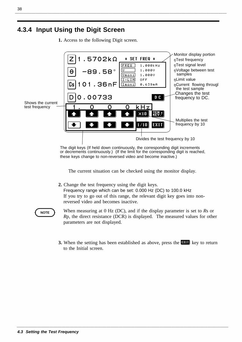
Shows the currenttest frequency
The digit keys (If held down continuously, the corresponding digit incrementsor decrements continuously.) (If the limit for the corresponding digit is reached,these keys change to non-reversed video and become inactive.)
Changes the testfrequency to DC.
Monitor display portion・Test frequency・Test signal level・Voltage between test
samples・Limit value・Current flowing throughthe test sample
Divides the test frequency by 10
Multiplies the testfrequency by 10
NOTE
1. Access to the following Digit screen.
The current situation can be checked using the monitor display.
2. Change the test frequency using the digit keys.Frequency range which can be set: 0.000 Hz (DC) to 100.0 kHzIf you try to go out of this range, the relevant digit key goes into non-reversed video and becomes inactive.
When measuring at 0 Hz (DC), and if the display parameter is set to Rs orRp, the direct resistance (DCR) is displayed. The measured values for otherparameters are not displayed.
3. When the setting has been established as above, press the key to returnto the Initial screen.
39
4.4 Setting the Test Signal Level
4.4.1 Control Screen Sequence
Menu screen
Test signal level setting screen
Set opencircuit voltage(V)
Set constantvoltage (CV)
Set constantcurrent (CC)
Initial screen
Initial screen
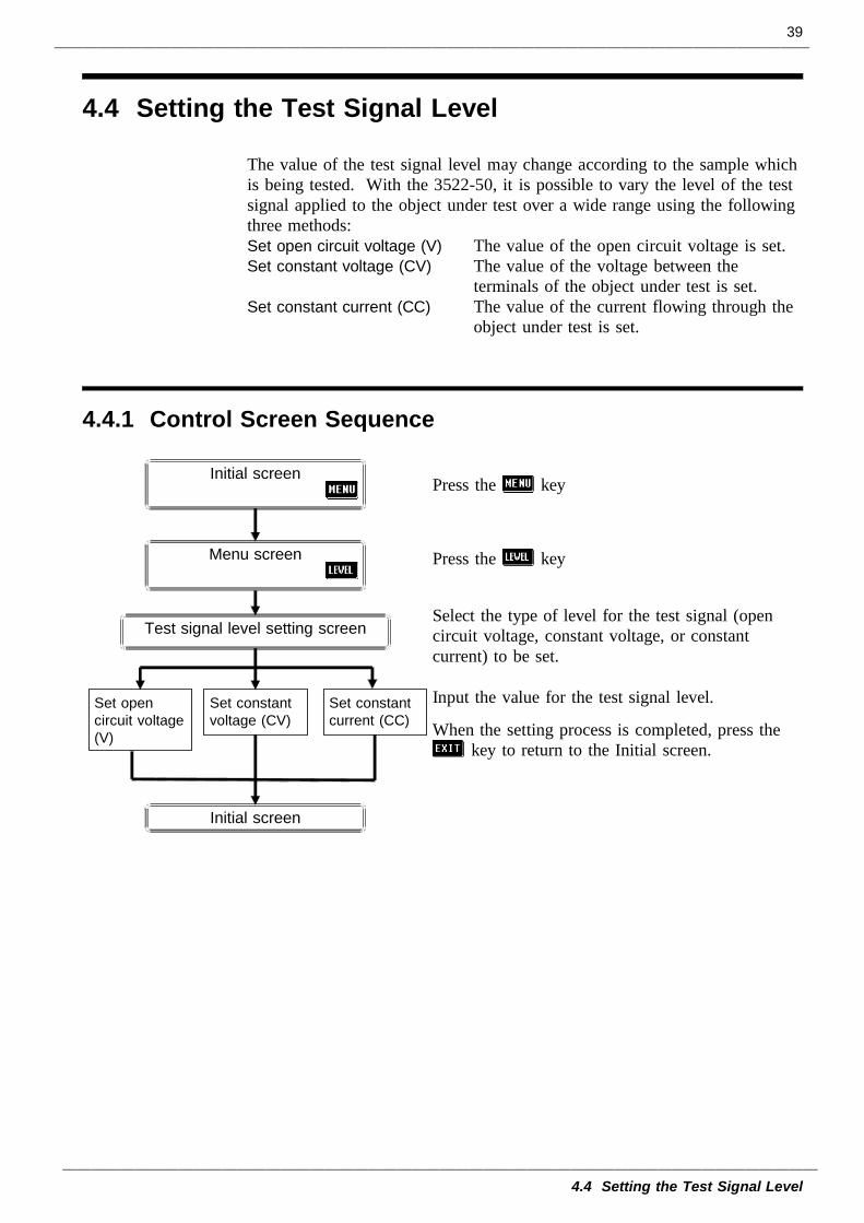
4.4 Setting the Test Signal Level
The value of the test signal level may change according to the sample whichis being tested. With the 3522-50, it is possible to vary the level of the testsignal applied to the object under test over a wide range using the followingthree methods:Set open circuit voltage (V) The value of the open circuit voltage is set.Set constant voltage (CV) The value of the voltage between the
terminals of the object under test is set.Set constant current (CC) The value of the current flowing through the
object under test is set.
Press the key
Press the key
Select the type of level for the test signal (opencircuit voltage, constant voltage, or constantcurrent) to be set.
Input the value for the test signal level.
When the setting process is completed, press thekey to return to the Initial screen.
40
4.4 Setting the Test Signal Level
4.4.2 Selecting the Level Type
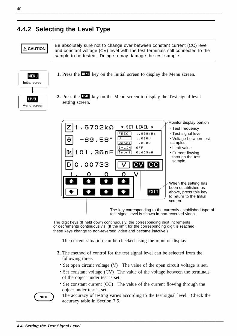
CAUTIONBe absolutely sure not to change over between constant current (CC) leveland constant voltage (CV) level with the test terminals still connected to thesample to be tested. Doing so may damage the test sample.
Initial screen
Menu screen
When the setting hasbeen established asabove, press this keyto return to the Initialscreen.
The digit keys (If held down continuously, the corresponding digit incrementsor decrements continuously.) (If the limit for the corresponding digit is reached,these keys change to non-reversed video and become inactive.)
The key corresponding to the currently established type oftest signal level is shown in non-reversed video.
Monitor display portionTest frequencyTest signal levelVoltage between test
samplesLimit valueCurrent flowingthrough the testsample
NOTE
1. Press the key on the Initial screen to display the Menu screen.
2. Press the key on the Menu screen to display the Test signal levelsetting screen.
The current situation can be checked using the monitor display.
3. The method of control for the test signal level can be selected from thefollowing three:Set open circuit voltage (V) The value of the open circuit voltage is set.Set constant voltage (CV) The value of the voltage between the terminalsof the object under test is set.Set constant current (CC) The value of the current flowing through theobject under test is set.The accuracy of testing varies according to the test signal level. Check theaccuracy table in Section 7.5.
41
4.4 Setting the Test Signal Level
NOTE
Constant voltage level
CC
CV
H L
V
Object under test
Output impedance
Open circuit voltage level
Constant current level
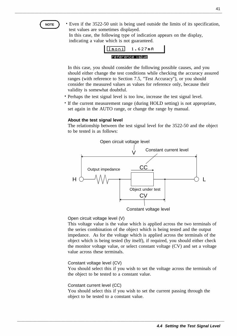
Even if the 3522-50 unit is being used outside the limits of its specification,test values are sometimes displayed.In this case, the following type of indication appears on the display,indicating a value which is not guaranteed.
In this case, you should consider the following possible causes, and youshould either change the test conditions while checking the accuracy assuredranges (with reference to Section 7.5, "Test Accuracy"), or you shouldconsider the measured values as values for reference only, because theirvalidity is somewhat doubtful.Perhaps the test signal level is too low, increase the test signal level.If the current measurement range (during HOLD setting) is not appropriate,set again in the AUTO range, or change the range by manual.
About the test signal levelThe relationship between the test signal level for the 3522-50 and the objectto be tested is as follows:
Open circuit voltage level (V)This voltage value is the value which is applied across the two terminals ofthe series combination of the object which is being tested and the outputimpedance. As for the voltage which is applied across the terminals of theobject which is being tested (by itself), if required, you should either checkthe monitor voltage value, or select constant voltage (CV) and set a voltagevalue across these terminals.
Constant voltage level (CV)You should select this if you wish to set the voltage across the terminals ofthe object to be tested to a constant value.
Constant current level (CC)You should select this if you wish to set the current passing through theobject to be tested to a constant value.
42
4.4 Setting the Test Signal Level
4.4.3 Setting the Open Circuit Voltage (V) Level
Test signal levelsetting screen
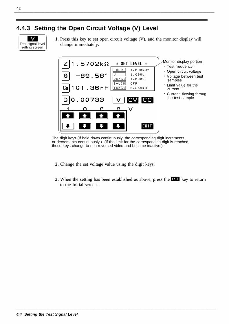
The digit keys (If held down continuously, the corresponding digit incrementsor decrements continuously.) (If the limit for the corresponding digit is reached,these keys change to non-reversed video and become inactive.)
Monitor display portionTest frequencyOpen circuit voltageVoltage between testsamplesLimit value for thecurrentCurrent flowing througthe test sample
1. Press this key to set open circuit voltage (V), and the monitor display willchange immediately.
2. Change the set voltage value using the digit keys.
3. When the setting has been established as above, press the key to returnto the Initial screen.
43
4.4 Setting the Test Signal Level
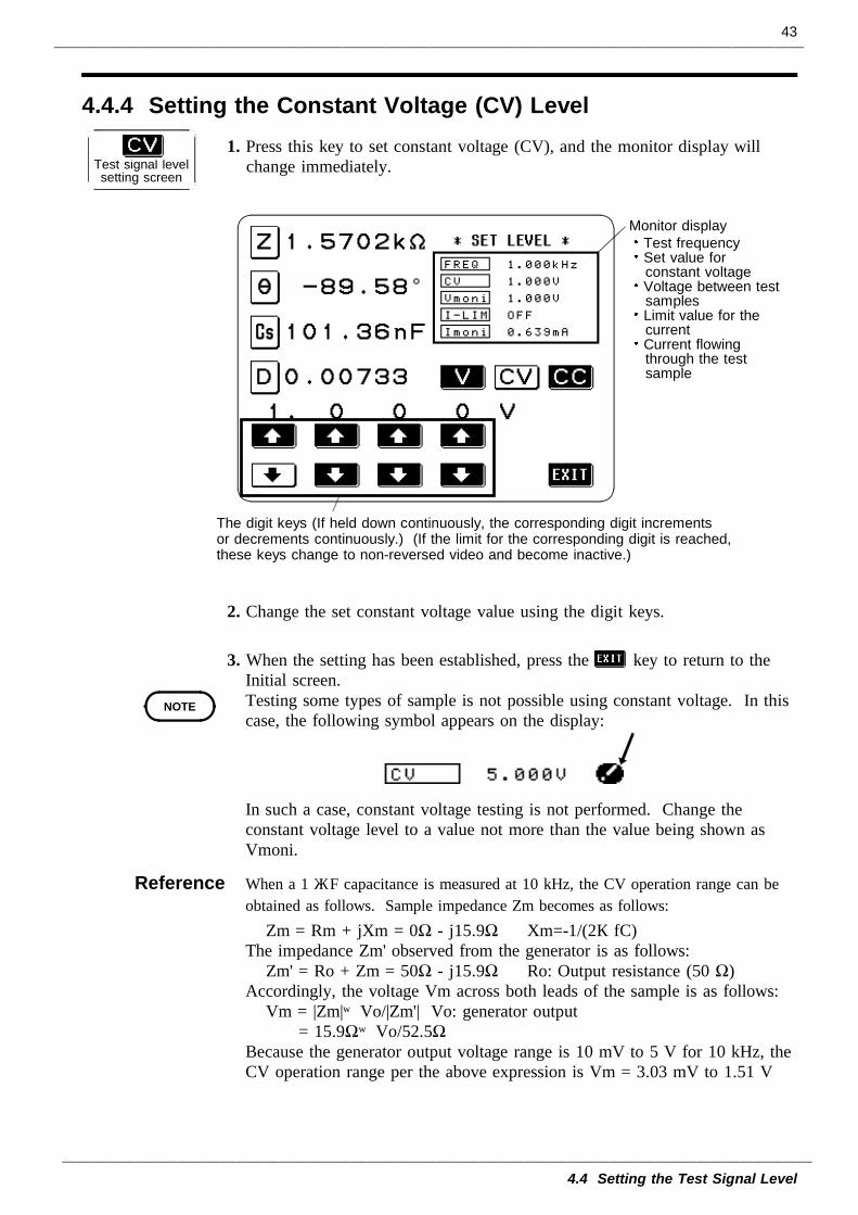
4.4.4 Setting the Constant Voltage (CV) Level
Test signal levelsetting screen
The digit keys (If held down continuously, the corresponding digit incrementsor decrements continuously.) (If the limit for the corresponding digit is reached,these keys change to non-reversed video and become inactive.)
Monitor displayTest frequencySet value forconstant voltageVoltage between testsamplesLimit value for thecurrentCurrent flowingthrough the testsample
NOTE
1. Press this key to set constant voltage (CV), and the monitor display willchange immediately.
2. Change the set constant voltage value using the digit keys.
3. When the setting has been established, press the key to return to theInitial screen.Testing some types of sample is not possible using constant voltage. In thiscase, the following symbol appears on the display:
In such a case, constant voltage testing is not performed. Change theconstant voltage level to a value not more than the value being shown asVmoni.
Reference When a 1 μF capacitance is measured at 10 kHz, the CV operation range can beobtained as follows. Sample impedance Zm becomes as follows:
Zm = Rm + jXm = 0Ω - j15.9Ω Xm=-1/(2πfC)The impedance Zm' observed from the generator is as follows:
Zm' = Ro + Zm = 50Ω - j15.9Ω Ro: Output resistance (50 Ω)Accordingly, the voltage Vm across both leads of the sample is as follows:
Vm = |Zm|×Vo/|Zm'| Vo: generator output= 15.9Ω×Vo/52.5Ω
Because the generator output voltage range is 10 mV to 5 V for 10 kHz, theCV operation range per the above expression is Vm = 3.03 mV to 1.51 V
44
4.4 Setting the Test Signal Level
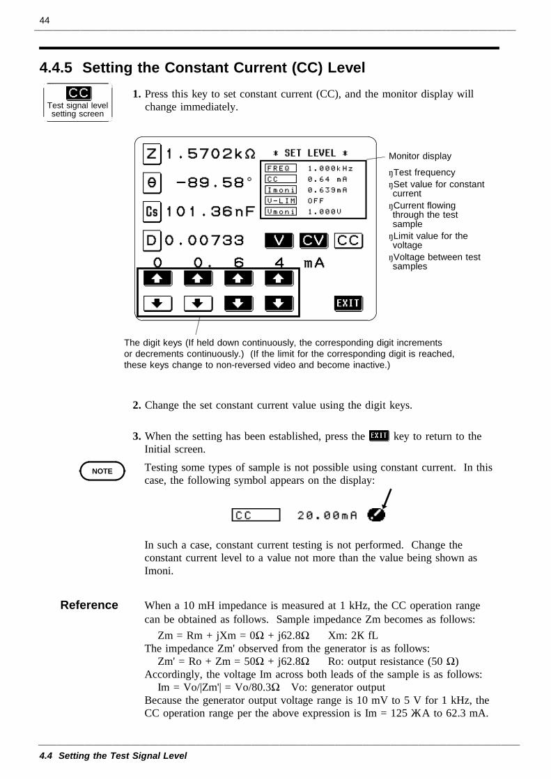
4.4.5 Setting the Constant Current (CC) Level
Test signal levelsetting screen
The digit keys (If held down continuously, the corresponding digit incrementsor decrements continuously.) (If the limit for the corresponding digit is reached,these keys change to non-reversed video and become inactive.)
Monitor display
・Test frequency・Set value for constantcurrent・Current flowingthrough the testsample・Limit value for thevoltage・Voltage between testsamples
NOTE
1. Press this key to set constant current (CC), and the monitor display willchange immediately.
2. Change the set constant current value using the digit keys.
3. When the setting has been established, press the key to return to theInitial screen.Testing some types of sample is not possible using constant current. In thiscase, the following symbol appears on the display:
In such a case, constant current testing is not performed. Change theconstant current level to a value not more than the value being shown asImoni.
Reference When a 10 mH impedance is measured at 1 kHz, the CC operation rangecan be obtained as follows. Sample impedance Zm becomes as follows:
Zm = Rm + jXm = 0Ω + j62.8Ω Xm: 2πfLThe impedance Zm' observed from the generator is as follows:
Zm' = Ro + Zm = 50Ω + j62.8Ω Ro: output resistance (50 Ω)Accordingly, the voltage Im across both leads of the sample is as follows:
Im = Vo/|Zm'| = Vo/80.3Ω Vo: generator outputBecause the generator output voltage range is 10 mV to 5 V for 1 kHz, theCC operation range per the above expression is Im = 125 μA to 62.3 mA.
45
4.5 Setting the Voltage/Current Limit
4.5.1 Control Screen Sequence
Initial screen
Menu screen
Limit setting screen
Initial screen
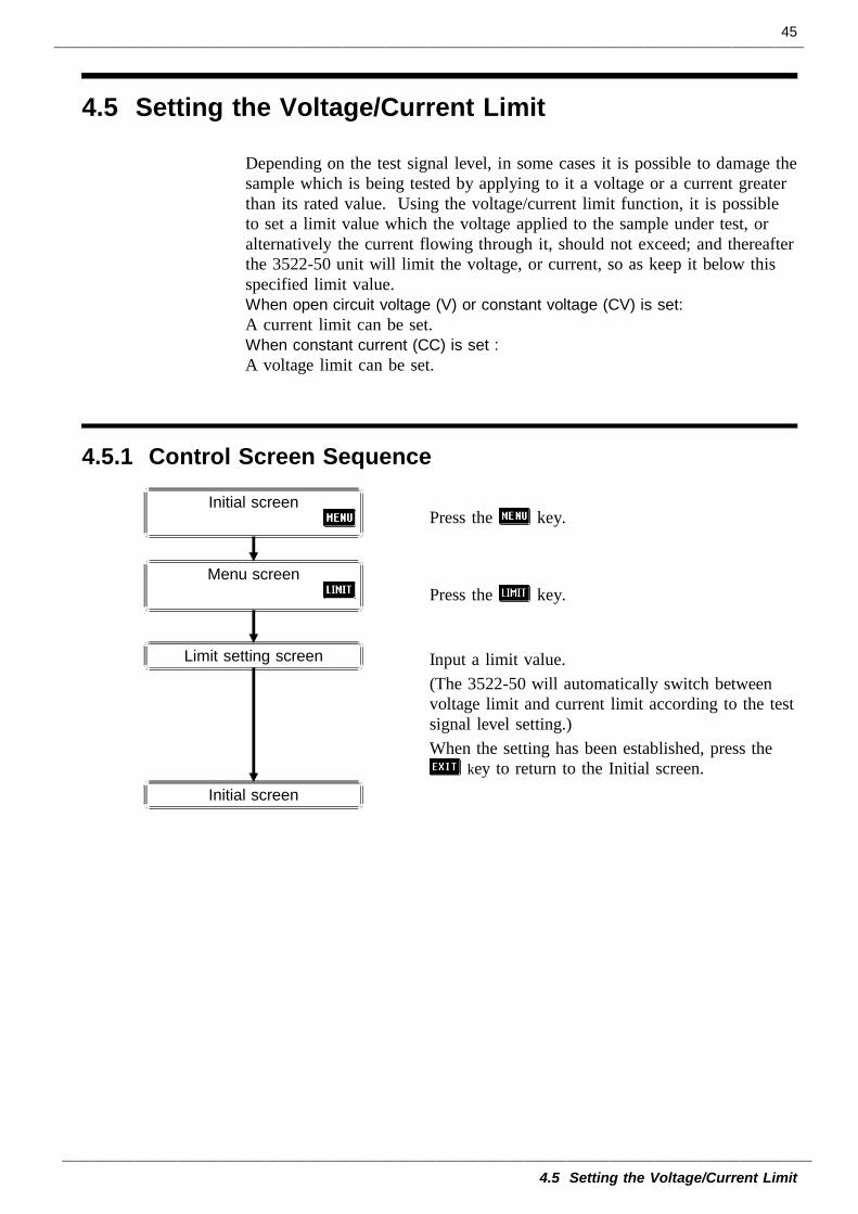
4.5 Setting the Voltage/Current Limit
Depending on the test signal level, in some cases it is possible to damage thesample which is being tested by applying to it a voltage or a current greaterthan its rated value. Using the voltage/current limit function, it is possibleto set a limit value which the voltage applied to the sample under test, oralternatively the current flowing through it, should not exceed; and thereafterthe 3522-50 unit will limit the voltage, or current, so as keep it below thisspecified limit value.When open circuit voltage (V) or constant voltage (CV) is set:A current limit can be set.When constant current (CC) is set :A voltage limit can be set.
Press the key.
Press the key.
Input a limit value.(The 3522-50 will automatically switch betweenvoltage limit and current limit according to the testsignal level setting.)When the setting has been established, press the
key to return to the Initial screen.
46
4.5 Setting the Voltage/Current Limit
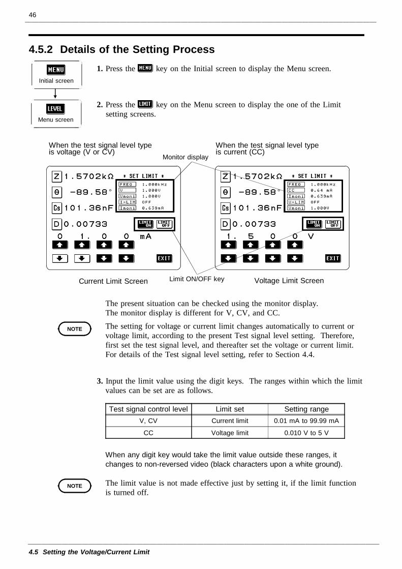
4.5.2 Details of the Setting Process
Initial screen
Menu screen
Monitor display
Voltage Limit ScreenCurrent Limit Screen Limit ON/OFF key
When the test signal level typeis voltage (V or CV)
When the test signal level typeis current (CC)
NOTE
Test signal control level Limit set Setting rangeV, CV Current limit 0.01 mA to 99.99 mA
CC Voltage limit 0.010 V to 5 V
NOTE
1. Press the key on the Initial screen to display the Menu screen.
2. Press the key on the Menu screen to display the one of the Limitsetting screens.
The present situation can be checked using the monitor display.The monitor display is different for V, CV, and CC.The setting for voltage or current limit changes automatically to current orvoltage limit, according to the present Test signal level setting. Therefore,first set the test signal level, and thereafter set the voltage or current limit.For details of the Test signal level setting, refer to Section 4.4.
3. Input the limit value using the digit keys. The ranges within which the limitvalues can be set are as follows.
When any digit key would take the limit value outside these ranges, itchanges to non-reversed video (black characters upon a white ground).
The limit value is not made effective just by setting it, if the limit functionis turned off.
47
4.5 Setting the Voltage/Current Limit
NOTE
When the constant voltage (CV) is set:
When the constant voltage (CV) is set:
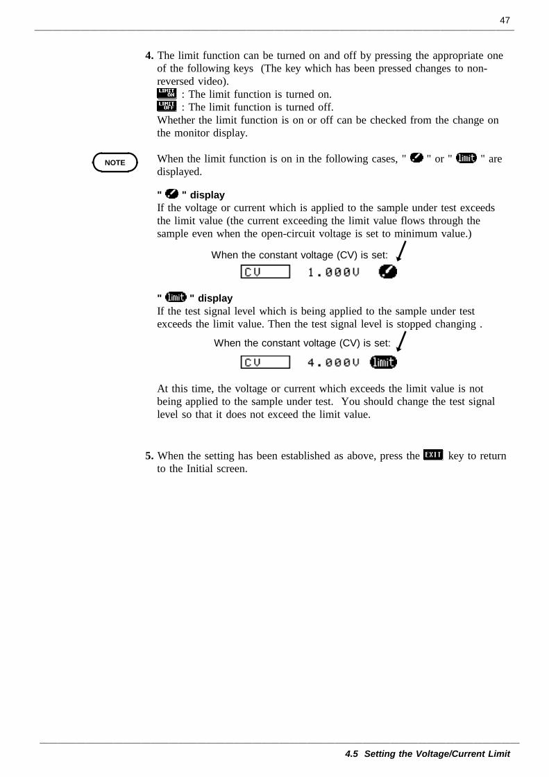
4. The limit function can be turned on and off by pressing the appropriate oneof the following keys (The key which has been pressed changes to non-reversed video).
: The limit function is turned on.: The limit function is turned off.
Whether the limit function is on or off can be checked from the change onthe monitor display.
When the limit function is on in the following cases, " " or " " aredisplayed.
" " displayIf the voltage or current which is applied to the sample under test exceedsthe limit value (the current exceeding the limit value flows through thesample even when the open-circuit voltage is set to minimum value.)
" " displayIf the test signal level which is being applied to the sample under testexceeds the limit value. Then the test signal level is stopped changing .
At this time, the voltage or current which exceeds the limit value is notbeing applied to the sample under test. You should change the test signallevel so that it does not exceed the limit value.
5. When the setting has been established as above, press the key to returnto the Initial screen.
48
4.6 Setting the Ranging
NOTE
4.6.1 Control Screen Sequence
Initial screen
Ranging setting screen
Set to AUTORange setting isperformed automatically
Set to HOLDRange setting isperformed manually
Initial screen
Menu screen
4.6 Setting the Ranging
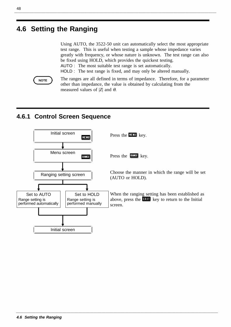
Using AUTO, the 3522-50 unit can automatically select the most appropriatetest range. This is useful when testing a sample whose impedance variesgreatly with frequency, or whose nature is unknown. The test range can alsobe fixed using HOLD, which provides the quickest testing.AUTO : The most suitable test range is set automatically.HOLD : The test range is fixed, and may only be altered manually.The ranges are all defined in terms of impedance. Therefore, for a parameterother than impedance, the value is obtained by calculating from themeasured values of |Z| and θ.
Press the key.
Press the key.
Choose the manner in which the range will be set(AUTO or HOLD).
When the ranging setting has been established asabove, press the key to return to the Initialscreen.
49
4.6 Setting the Ranging
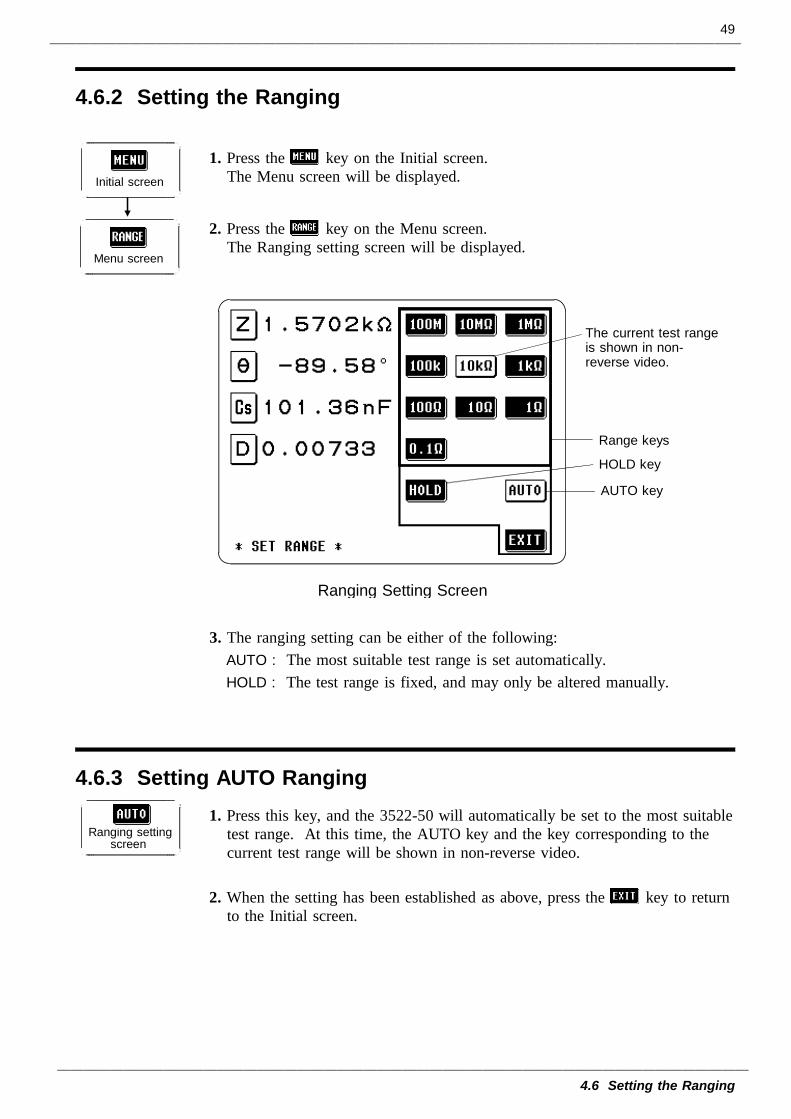
4.6.2 Setting the Ranging
Initial screen
Menu screen
The current test rangeis shown in non-reverse video.
Range keys
HOLD key
AUTO key
Ranging Setting Screen
4.6.3 Setting AUTO Ranging
Ranging settingscreen
1. Press the key on the Initial screen.The Menu screen will be displayed.
2. Press the key on the Menu screen.The Ranging setting screen will be displayed.
3. The ranging setting can be either of the following:AUTO : The most suitable test range is set automatically.HOLD : The test range is fixed, and may only be altered manually.
1. Press this key, and the 3522-50 will automatically be set to the most suitabletest range. At this time, the AUTO key and the key corresponding to thecurrent test range will be shown in non-reverse video.
2. When the setting has been established as above, press the key to returnto the Initial screen.
50
4.6 Setting the Ranging
4.6.4 Setting the Ranging to HOLD
Ranging settingscreen
Test range[Ω]
Range of impedance which can bemeasured within the accuracy guaranteed
[Ω]0.1 10.00 m to 99.99 m
1 80.00 m to 999.99 m
10 0.8000 to 9.9999
100 8.000 to 99.999
1 k 80.00 to 999.99
10 k 0.8000 k to 9.9999 k
100 k 8.000 k to 99.999 k
1 M 80.00 k to 999.99 k
10 M 0.8000 M to 9.9999 M
100 M 8.0000 M to 200.00M
NOTE
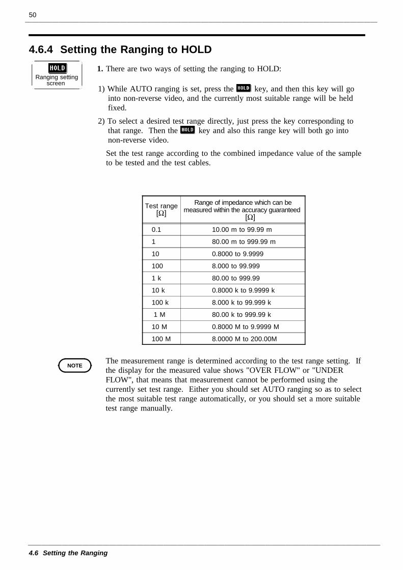
1. There are two ways of setting the ranging to HOLD:
1) While AUTO ranging is set, press the key, and then this key will gointo non-reverse video, and the currently most suitable range will be heldfixed.
2) To select a desired test range directly, just press the key corresponding tothat range. Then the key and also this range key will both go intonon-reverse video.Set the test range according to the combined impedance value of the sampleto be tested and the test cables.
The measurement range is determined according to the test range setting. Ifthe display for the measured value shows "OVER FLOW" or "UNDERFLOW", that means that measurement cannot be performed using thecurrently set test range. Either you should set AUTO ranging so as to selectthe most suitable test range automatically, or you should set a more suitabletest range manually.
51
4.6 Setting the Ranging
NOTE
2. When the setting has been established as above, press the key to returnto the Initial screen.In the case of a test sample whose impedance changes according to thefrequency, when testing is being performed with HOLD set, it may happen,when the frequency is changed over, that measurement cannot be continuedto be performed upon the same test range. You should change the testrange if this happens.
The test range setting is made according to the combination of theimpedances of the sample being tested and the test cables. Therefore it canhappen that testing is not possible, if the test range is held with HOLD onlyupon the basis of the impedance of the sample under test. If this happens,you should change the test range, making reference to Section 4.9, "OpenCircuit Compensation and Short Circuit Compensation".Even if the 3522-50 unit is being used outside the limits of its specification,test values are sometimes displayed.In this case, the following type of indication "reference value" appears on thedisplay, indicating a value which is not guaranteed.
In this case, you should consider the following possible cause, and youshould either change the test conditions while checking the accuracy assuredranges (with reference to Section 7.5, "Test Accuracy"), or you shouldconsider the measured values as values for reference only, because theirvalidity is somewhat doubtful.When the present test range (when HOLD is set) is not suitable:Either you should set AUTO ranging so as to select the most suitable testrange automatically, or you should set a more suitable test range manually.
52
4.7 Open Circuit Compensation
NOTE
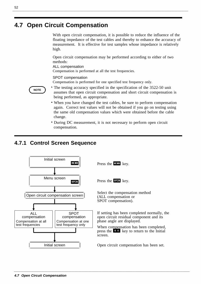
4.7.1 Control Screen Sequence
Press the key.
Press the key.
Select the compensation method(ALL compensation orSPOT compensation).
If setting has been completed normally, theopen circuit residual component and itsphase angle are displayed.When compensation has been completed,press the key to return to the Initialscreen.
Open circuit compensation has been set.Initial screen
Open circuit compensation screen
ALLcompensation
Compensation at alltest frequencies
SPOTcompensation
Compensation at onetest frequency only
Initial screen
Menu screen
4.7 Open Circuit CompensationWith open circuit compensation, it is possible to reduce the influence of thefloating impedance of the test cables and thereby to enhance the accuracy ofmeasurement. It is effective for test samples whose impedance is relativelyhigh.
Open circuit compensation may be performed according to either of twomethods:ALL compensation Compensation is performed at all the test frequencies.
SPOT compensation Compensation is performed for one specified test frequency only.The testing accuracy specified in the specification of the 3522-50 unitassumes that open circuit compensation and short circuit compensation isbeing performed, as appropriate.When you have changed the test cables, be sure to perform compensationagain. Correct test values will not be obtained if you go on testing usingthe same old compensation values which were obtained before the cablechange.During DC measurement, it is not necessary to perform open circuitcompensation.
53
4.7 Open Circuit Compensation
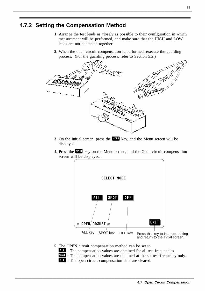
4.7.2 Setting the Compensation Method
ALL key Press this key to interrupt settingand return to the Initial screen.
OFF keySPOT key
1. Arrange the test leads as closely as possible to their configuration in whichmeasurement will be performed, and make sure that the HIGH and LOWleads are not contacted together.
2. When the open circuit compensation is performed, execute the guardingprocess. (For the guarding process, refer to Section 5.2.)
3. On the Initial screen, press the key, and the Menu screen will bedisplayed.
4. Press the key on the Menu screen, and the Open circuit compensationscreen will be displayed.
5. The OPEN circuit compensation method can be set to:: The compensation values are obtained for all test frequencies.: The compensation values are obtained at the set test frequency only.: The open circuit compensation data are cleared.
54
4.7 Open Circuit Compensation
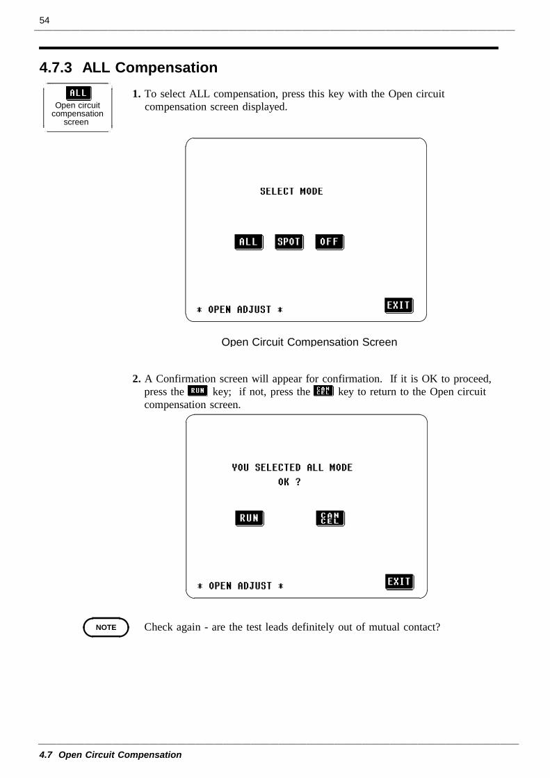
4.7.3 ALL Compensation
Open circuitcompensation
screen
Open Circuit Compensation Screen
NOTE
1. To select ALL compensation, press this key with the Open circuitcompensation screen displayed.
2. A Confirmation screen will appear for confirmation. If it is OK to proceed,press the key; if not, press the key to return to the Open circuitcompensation screen.
Check again - are the test leads definitely out of mutual contact?
55
4.7 Open Circuit Compensation
Open circuitresidualcomponent
Phase angle
NOTE
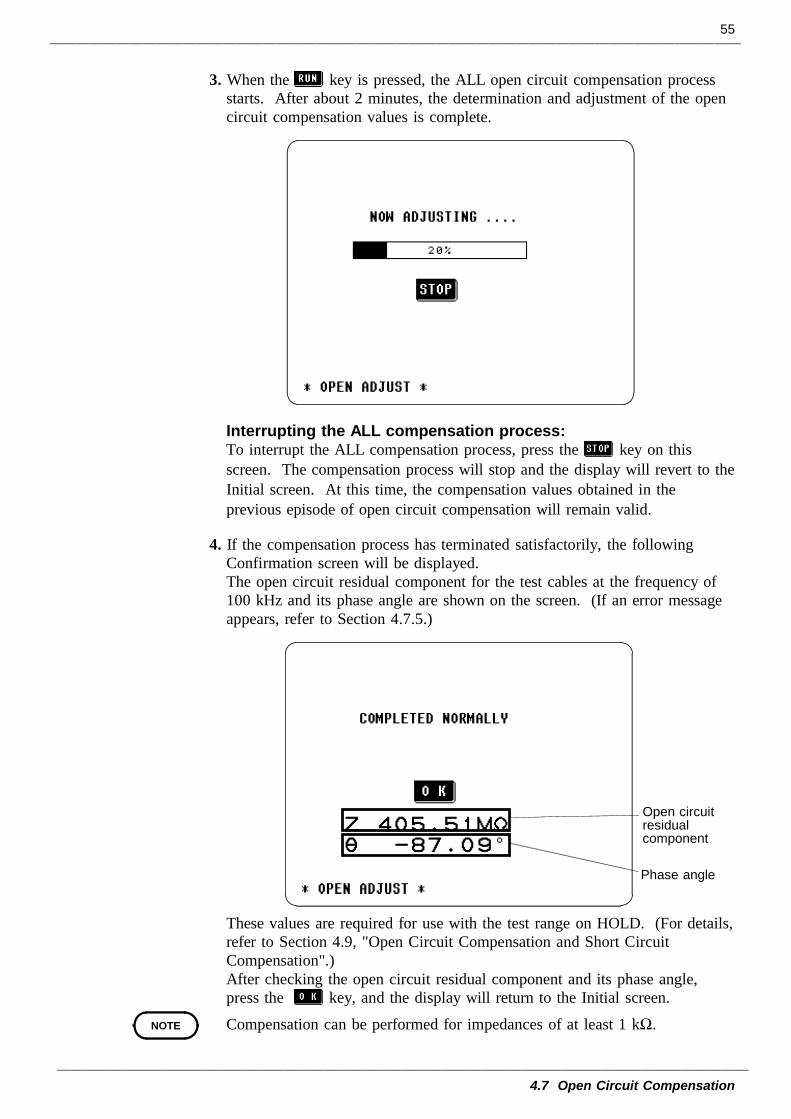
3. When the key is pressed, the ALL open circuit compensation processstarts. After about 2 minutes, the determination and adjustment of the opencircuit compensation values is complete.
Interrupting the ALL compensation process:To interrupt the ALL compensation process, press the key on thisscreen. The compensation process will stop and the display will revert to theInitial screen. At this time, the compensation values obtained in theprevious episode of open circuit compensation will remain valid.
4. If the compensation process has terminated satisfactorily, the followingConfirmation screen will be displayed.The open circuit residual component for the test cables at the frequency of100 kHz and its phase angle are shown on the screen. (If an error messageappears, refer to Section 4.7.5.)
These values are required for use with the test range on HOLD. (For details,refer to Section 4.9, "Open Circuit Compensation and Short CircuitCompensation".)After checking the open circuit residual component and its phase angle,press the key, and the display will return to the Initial screen.
Compensation can be performed for impedances of at least 1 kΩ.
56
4.7 Open Circuit Compensation
4.7.4 Spot Compensation
Open circuitcompensation
screen
Open Circuit Compensation Screen
Units keys (shown in non-reversed video, until a numerical valuefor the frequency has been input)
Numerickeypad
Previousfrequency
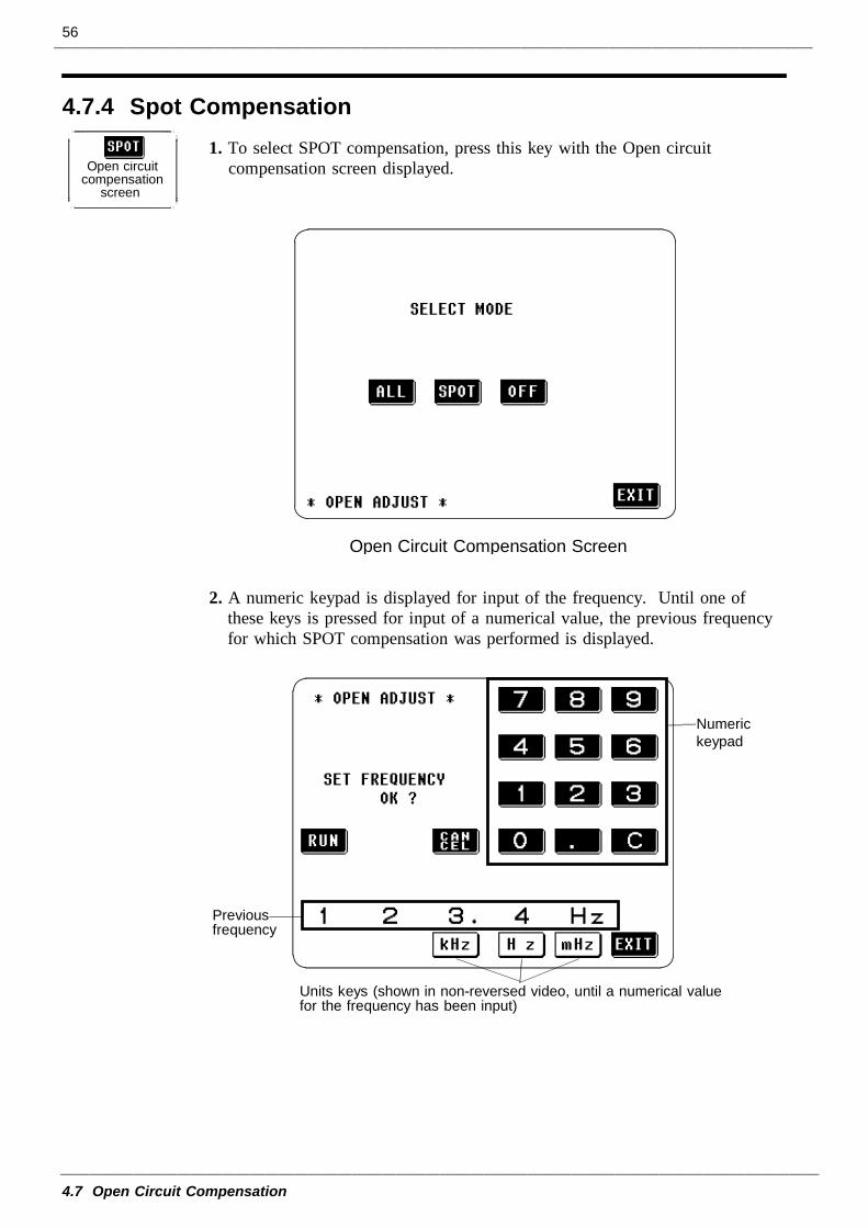
1. To select SPOT compensation, press this key with the Open circuitcompensation screen displayed.
2. A numeric keypad is displayed for input of the frequency. Until one ofthese keys is pressed for input of a numerical value, the previous frequencyfor which SPOT compensation was performed is displayed.
57
4.7 Open Circuit Compensation
NOTE
NOTE
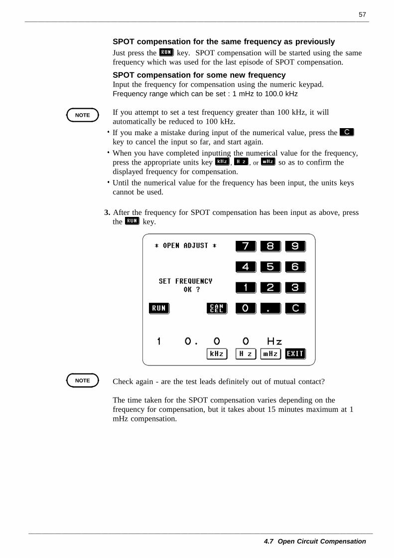
SPOT compensation for the same frequency as previouslyJust press the key. SPOT compensation will be started using the samefrequency which was used for the last episode of SPOT compensation.SPOT compensation for some new frequencyInput the frequency for compensation using the numeric keypad.Frequency range which can be set : 1 mHz to 100.0 kHz
If you attempt to set a test frequency greater than 100 kHz, it willautomatically be reduced to 100 kHz.If you make a mistake during input of the numerical value, press thekey to cancel the input so far, and start again.When you have completed inputting the numerical value for the frequency,press the appropriate units key , , or so as to confirm thedisplayed frequency for compensation.Until the numerical value for the frequency has been input, the units keyscannot be used.
3. After the frequency for SPOT compensation has been input as above, pressthe key.
Check again - are the test leads definitely out of mutual contact?
The time taken for the SPOT compensation varies depending on thefrequency for compensation, but it takes about 15 minutes maximum at 1mHz compensation.
58
4.7 Open Circuit Compensation
Open circuitresidualcomponent
Phase angle
NOTE
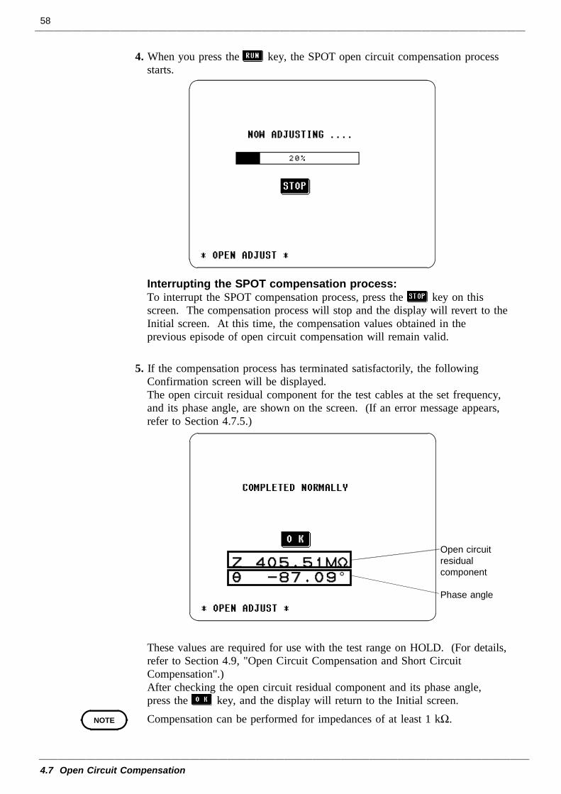
4. When you press the key, the SPOT open circuit compensation processstarts.
Interrupting the SPOT compensation process:To interrupt the SPOT compensation process, press the key on thisscreen. The compensation process will stop and the display will revert to theInitial screen. At this time, the compensation values obtained in theprevious episode of open circuit compensation will remain valid.
5. If the compensation process has terminated satisfactorily, the followingConfirmation screen will be displayed.The open circuit residual component for the test cables at the set frequency,and its phase angle, are shown on the screen. (If an error message appears,refer to Section 4.7.5.)
These values are required for use with the test range on HOLD. (For details,refer to Section 4.9, "Open Circuit Compensation and Short CircuitCompensation".)After checking the open circuit residual component and its phase angle,press the key, and the display will return to the Initial screen.Compensation can be performed for impedances of at least 1 kΩ.
59
4.7 Open Circuit Compensation
4.7.5 When an Error Message Appears and Compensation HasStopped
4.7.6 Clearing Compensation Data
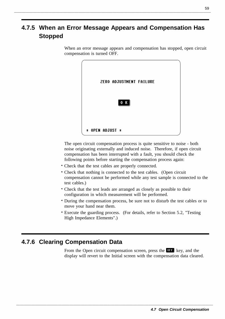
When an error message appears and compensation has stopped, open circuitcompensation is turned OFF.
The open circuit compensation process is quite sensitive to noise - bothnoise originating externally and induced noise. Therefore, if open circuitcompensation has been interrupted with a fault, you should check thefollowing points before starting the compensation process again:Check that the test cables are properly connected.Check that nothing is connected to the test cables. (Open circuitcompensation cannot be performed while any test sample is connected to thetest cables.)Check that the test leads are arranged as closely as possible to theirconfiguration in which measurement will be performed.During the compensation process, be sure not to disturb the test cables or tomove your hand near them.Execute the guarding process. (For details, refer to Section 5.2, "TestingHigh Impedance Elements".)
From the Open circuit compensation screen, press the key, and thedisplay will revert to the Initial screen with the compensation data cleared.
60
4.8 Short Circuit Compensation
NOTE
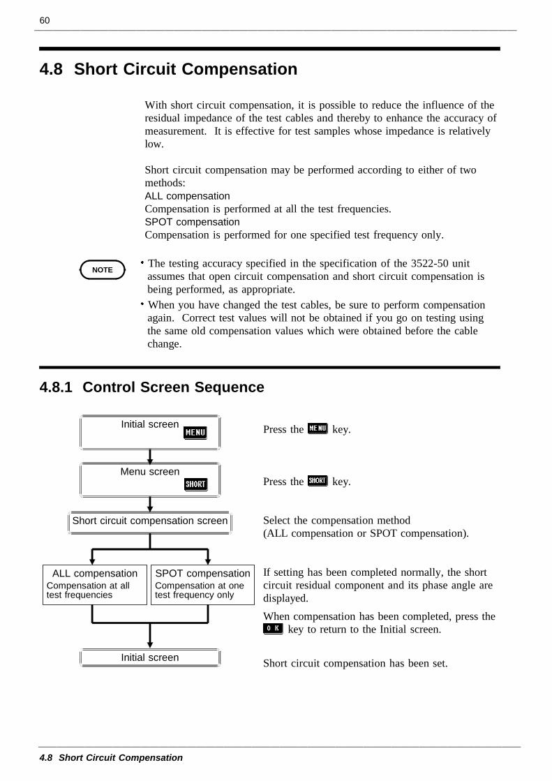
4.8.1 Control Screen Sequence
Initial screen
Menu screen
Initial screen
Short circuit compensation screen
ALL compensationCompensation at alltest frequencies
SPOT compensationCompensation at onetest frequency only
4.8 Short Circuit Compensation
With short circuit compensation, it is possible to reduce the influence of theresidual impedance of the test cables and thereby to enhance the accuracy ofmeasurement. It is effective for test samples whose impedance is relativelylow.
Short circuit compensation may be performed according to either of twomethods:ALL compensation Compensation is performed at all the test frequencies.SPOT compensationCompensation is performed for one specified test frequency only.
The testing accuracy specified in the specification of the 3522-50 unitassumes that open circuit compensation and short circuit compensation isbeing performed, as appropriate.When you have changed the test cables, be sure to perform compensationagain. Correct test values will not be obtained if you go on testing usingthe same old compensation values which were obtained before the cablechange.
Press the key.
Press the key.
Select the compensation method(ALL compensation or SPOT compensation).
If setting has been completed normally, the shortcircuit residual component and its phase angle aredisplayed.When compensation has been completed, press the
key to return to the Initial screen.
Short circuit compensation has been set.
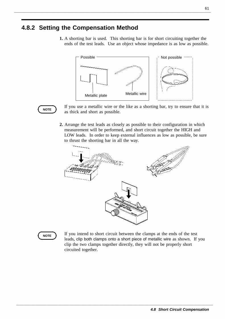
61
4.8 Short Circuit Compensation
4.8.2 Setting the Compensation Method
Metallic plate Metallic wire
Not possiblePossible
NOTE
NOTE
1. A shorting bar is used. This shorting bar is for short circuiting together theends of the test leads. Use an object whose impedance is as low as possible.
If you use a metallic wire or the like as a shorting bar, try to ensure that it isas thick and short as possible.
2. Arrange the test leads as closely as possible to their configuration in whichmeasurement will be performed, and short circuit together the HIGH andLOW leads. In order to keep external influences as low as possible, be sureto thrust the shorting bar in all the way.
If you intend to short circuit between the clamps at the ends of the testleads, clip both clamps onto a short piece of metallic wire as shown. If youclip the two clamps together directly, they will not be properly shortcircuited together.
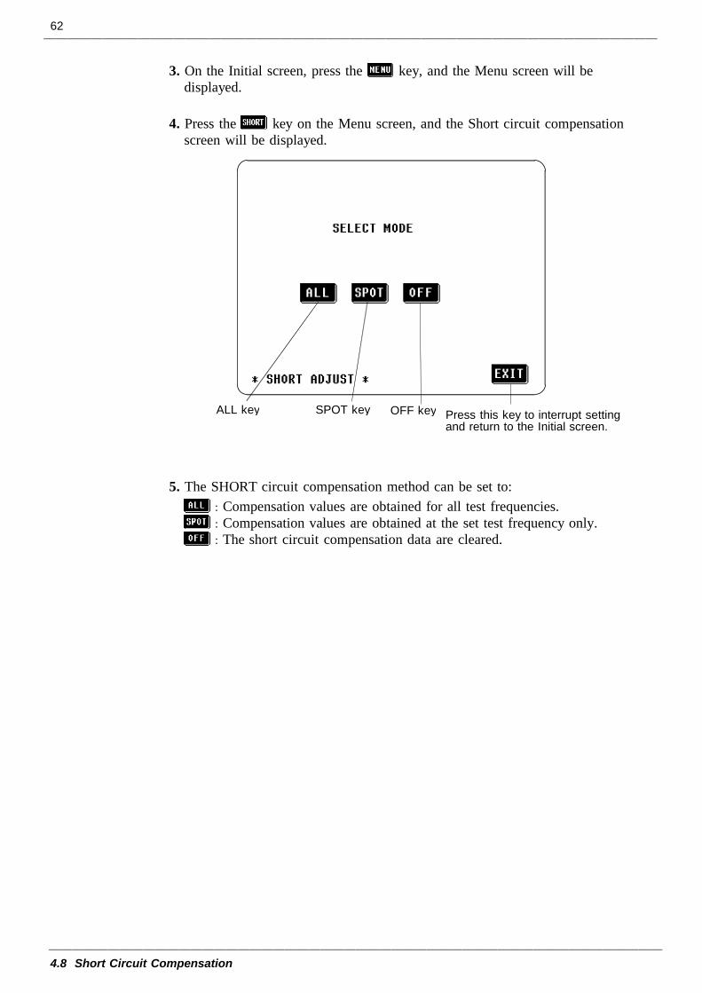
62
4.8 Short Circuit Compensation
ALL key Press this key to interrupt settingand return to the Initial screen.
OFF keySPOT key
3. On the Initial screen, press the key, and the Menu screen will bedisplayed.
4. Press the key on the Menu screen, and the Short circuit compensationscreen will be displayed.
5. The SHORT circuit compensation method can be set to:: Compensation values are obtained for all test frequencies.: Compensation values are obtained at the set test frequency only.: The short circuit compensation data are cleared.
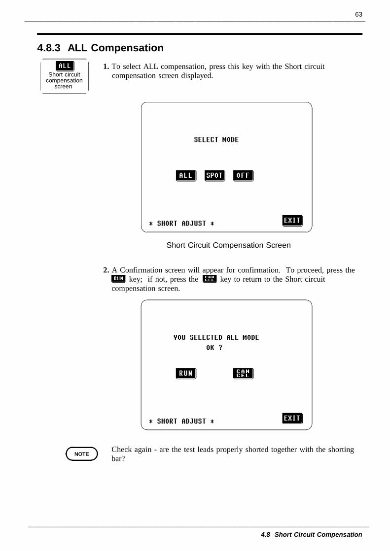
63
4.8 Short Circuit Compensation
4.8.3 ALL Compensation
Short circuitcompensation
screen
Short Circuit Compensation Screen
NOTE
1. To select ALL compensation, press this key with the Short circuitcompensation screen displayed.
2. A Confirmation screen will appear for confirmation. To proceed, press thekey; if not, press the key to return to the Short circuit
compensation screen.
Check again - are the test leads properly shorted together with the shortingbar?
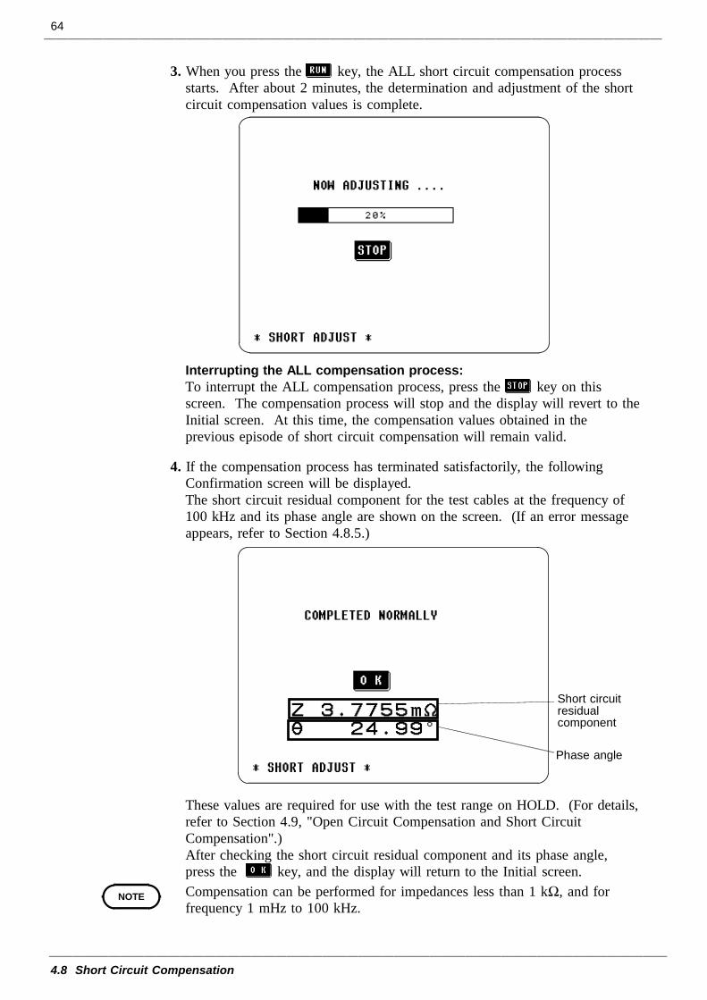
64
4.8 Short Circuit Compensation
Short circuitresidualcomponent
Phase angle
NOTE
3. When you press the key, the ALL short circuit compensation processstarts. After about 2 minutes, the determination and adjustment of the shortcircuit compensation values is complete.
Interrupting the ALL compensation process:To interrupt the ALL compensation process, press the key on thisscreen. The compensation process will stop and the display will revert to theInitial screen. At this time, the compensation values obtained in theprevious episode of short circuit compensation will remain valid.
4. If the compensation process has terminated satisfactorily, the followingConfirmation screen will be displayed.The short circuit residual component for the test cables at the frequency of100 kHz and its phase angle are shown on the screen. (If an error messageappears, refer to Section 4.8.5.)
These values are required for use with the test range on HOLD. (For details,refer to Section 4.9, "Open Circuit Compensation and Short CircuitCompensation".)After checking the short circuit residual component and its phase angle,press the key, and the display will return to the Initial screen.Compensation can be performed for impedances less than 1 kΩ, and forfrequency 1 mHz to 100 kHz.
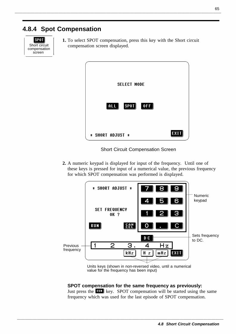
65
4.8 Short Circuit Compensation
4.8.4 Spot Compensation
Short circuitcompensation
screen
Short Circuit Compensation Screen
Units keys (shown in non-reversed video, until a numericalvalue for the frequency has been input)
Numerickeypad
Previousfrequency
Sets frequencyto DC.
1. To select SPOT compensation, press this key with the Short circuitcompensation screen displayed.
2. A numeric keypad is displayed for input of the frequency. Until one ofthese keys is pressed for input of a numerical value, the previous frequencyfor which SPOT compensation was performed is displayed.
SPOT compensation for the same frequency as previously:Just press the key. SPOT compensation will be started using the samefrequency which was used for the last episode of SPOT compensation.
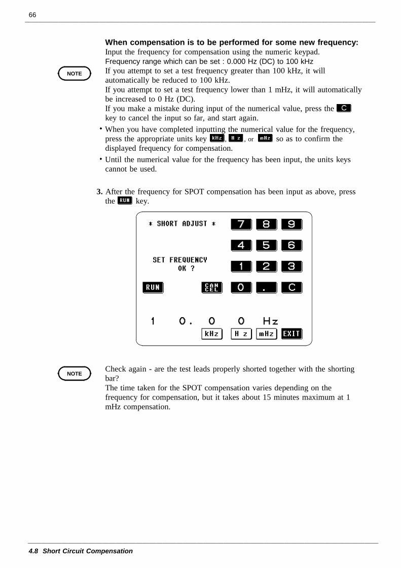
66
4.8 Short Circuit Compensation
NOTE
NOTE
When compensation is to be performed for some new frequency:Input the frequency for compensation using the numeric keypad.Frequency range which can be set : 0.000 Hz (DC) to 100 kHzIf you attempt to set a test frequency greater than 100 kHz, it willautomatically be reduced to 100 kHz.If you attempt to set a test frequency lower than 1 mHz, it will automaticallybe increased to 0 Hz (DC).If you make a mistake during input of the numerical value, press thekey to cancel the input so far, and start again.When you have completed inputting the numerical value for the frequency,press the appropriate units key , , or so as to confirm thedisplayed frequency for compensation.Until the numerical value for the frequency has been input, the units keyscannot be used.
3. After the frequency for SPOT compensation has been input as above, pressthe key.
Check again - are the test leads properly shorted together with the shortingbar?The time taken for the SPOT compensation varies depending on thefrequency for compensation, but it takes about 15 minutes maximum at 1mHz compensation.
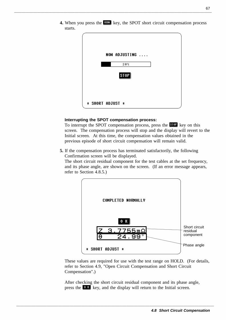
67
4.8 Short Circuit Compensation
Short circuitresidualcomponent
Phase angle
4. When you press the key, the SPOT short circuit compensation processstarts.
Interrupting the SPOT compensation process:To interrupt the SPOT compensation process, press the key on thisscreen. The compensation process will stop and the display will revert to theInitial screen. At this time, the compensation values obtained in theprevious episode of short circuit compensation will remain valid.
5. If the compensation process has terminated satisfactorily, the followingConfirmation screen will be displayed.The short circuit residual component for the test cables at the set frequency,and its phase angle, are shown on the screen. (If an error message appears,refer to Section 4.8.5.)
These values are required for use with the test range on HOLD. (For details,refer to Section 4.9, "Open Circuit Compensation and Short CircuitCompensation".)
After checking the short circuit residual component and its phase angle,press the key, and the display will return to the Initial screen.
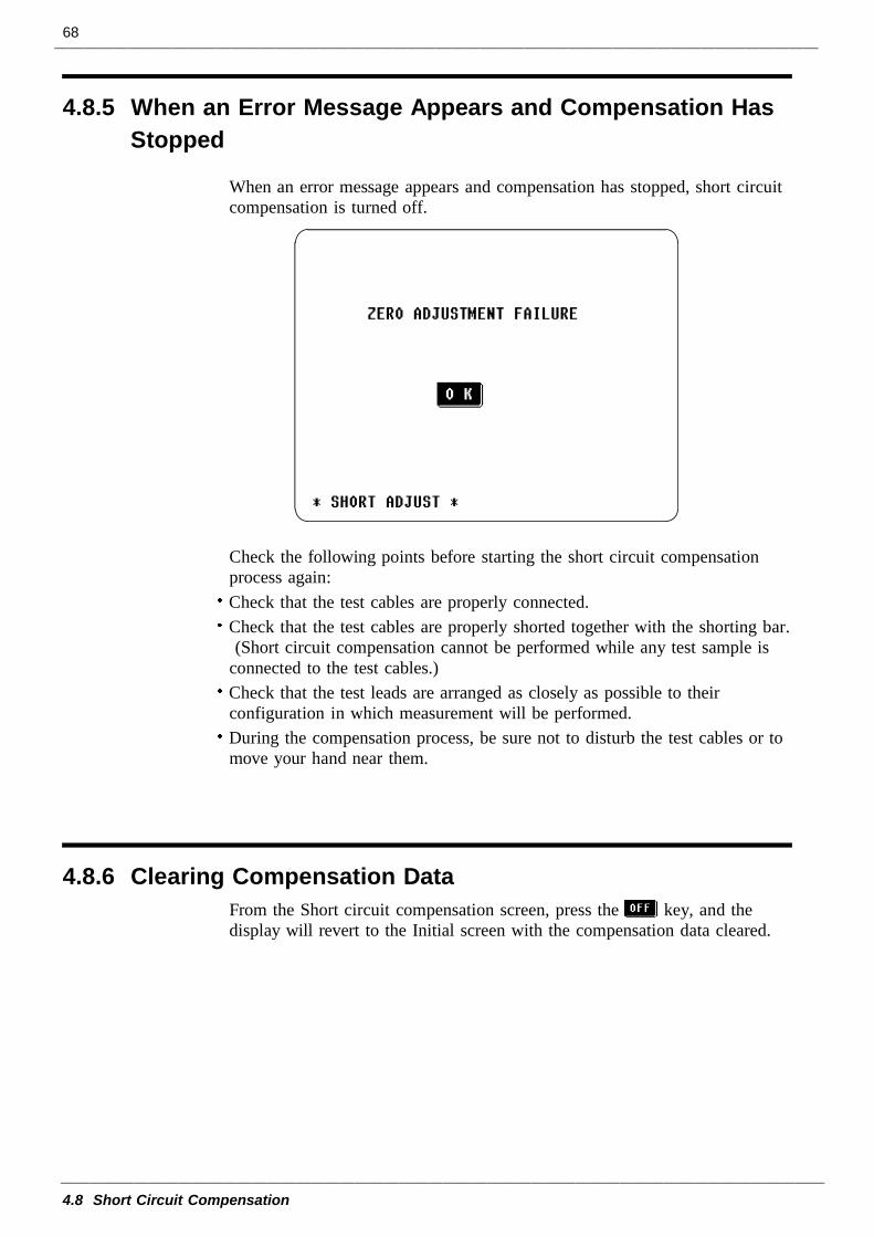
68
4.8 Short Circuit Compensation
4.8.5 When an Error Message Appears and Compensation HasStopped
4.8.6 Clearing Compensation Data
When an error message appears and compensation has stopped, short circuitcompensation is turned off.
Check the following points before starting the short circuit compensationprocess again:Check that the test cables are properly connected.Check that the test cables are properly shorted together with the shorting bar.(Short circuit compensation cannot be performed while any test sample is
connected to the test cables.)Check that the test leads are arranged as closely as possible to theirconfiguration in which measurement will be performed.During the compensation process, be sure not to disturb the test cables or tomove your hand near them.
From the Short circuit compensation screen, press the key, and thedisplay will revert to the Initial screen with the compensation data cleared.
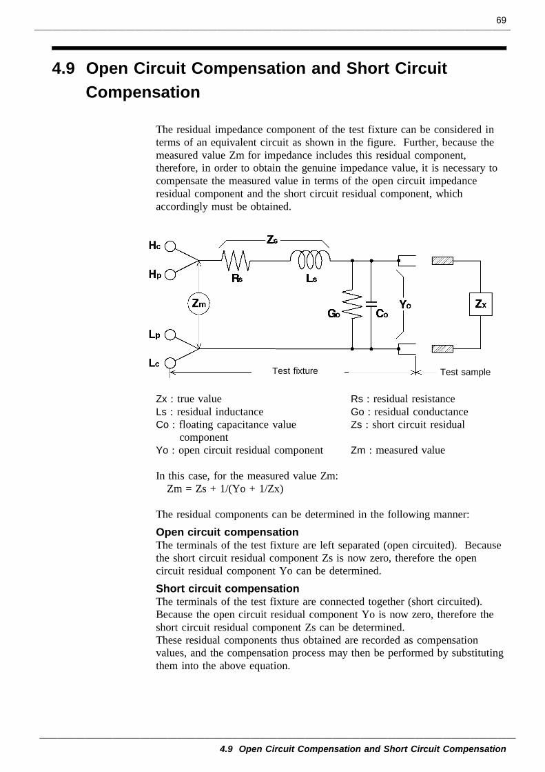
69
4.9 Open Circuit Compensation and Short Circuit Compensation
Test sampleTest fixture
4.9 Open Circuit Compensation and Short CircuitCompensation
The residual impedance component of the test fixture can be considered interms of an equivalent circuit as shown in the figure. Further, because themeasured value Zm for impedance includes this residual component,therefore, in order to obtain the genuine impedance value, it is necessary tocompensate the measured value in terms of the open circuit impedanceresidual component and the short circuit residual component, whichaccordingly must be obtained.
Zx : true value Rs : residual resistanceLs : residual inductance Go : residual conductanceCo : floating capacitance value Zs : short circuit residual
componentYo : open circuit residual component Zm : measured value
In this case, for the measured value Zm: Zm = Zs + 1/(Yo + 1/Zx)
The residual components can be determined in the following manner:Open circuit compensationThe terminals of the test fixture are left separated (open circuited). Becausethe short circuit residual component Zs is now zero, therefore the opencircuit residual component Yo can be determined.Short circuit compensationThe terminals of the test fixture are connected together (short circuited).Because the open circuit residual component Yo is now zero, therefore theshort circuit residual component Zs can be determined.These residual components thus obtained are recorded as compensationvalues, and the compensation process may then be performed by substitutingthem into the above equation.
70
4.9 Open Circuit Compensation and Short Circuit Compensation
NOTE
NOTE
The determination of test range is performed according to the measuredvalue Zm for impedance. Therefore it may happen that testing cannot beperformed, when HOLD is on, if the test range is determined merelyaccording to the value of impedance of the sample under test. In this case,you should set the test range in consideration both of the impedance of thetest sample and also of the residual impedance components of the testfixture.
Deviations in the measured values can become comparatively large inthe following cases:If only short circuit compensation has been performed.With short circuit compensation only having been performed, since nocompensation can be performed in terms of the open circuit residualcomponent Yo (which is not available), thereby deviation in the resultantvalues will become large if the value of that open circuit residual componentYo is relatively large.
If only open circuit compensation has been performed.With open circuit compensation only having been performed, since nocompensation can be performed in terms of the short circuit residualcomponent Zs (which is not available), thereby deviation in the resultantvalues will become large if the value of that short circuit residual componentZs is relatively large.
In order to avoid this sort of thing, be sure always to perform both shortcircuit compensation and also open circuit compensation.
During DC measurement, it is not possible to perform open circuitcompensation because the open circuit residual component Yo can beignored.
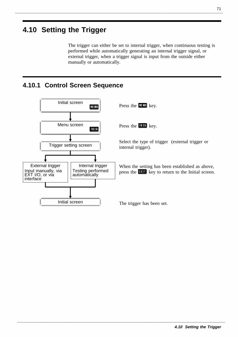
71
4.10 Setting the Trigger
4.10.1 Control Screen Sequence
Initial screen
Trigger setting screen
Internal triggerTesting performedautomatically
External triggerInput manually, viaEXT I/O, or viainterface
Initial screen
Menu screen
4.10 Setting the Trigger
The trigger can either be set to internal trigger, when continuous testing isperformed while automatically generating an internal trigger signal, orexternal trigger, when a trigger signal is input from the outside eithermanually or automatically.
Press the key.
Press the key.
Select the type of trigger (external trigger orinternal trigger).
When the setting has been established as above,press the key to return to the Initial screen.
The trigger has been set.
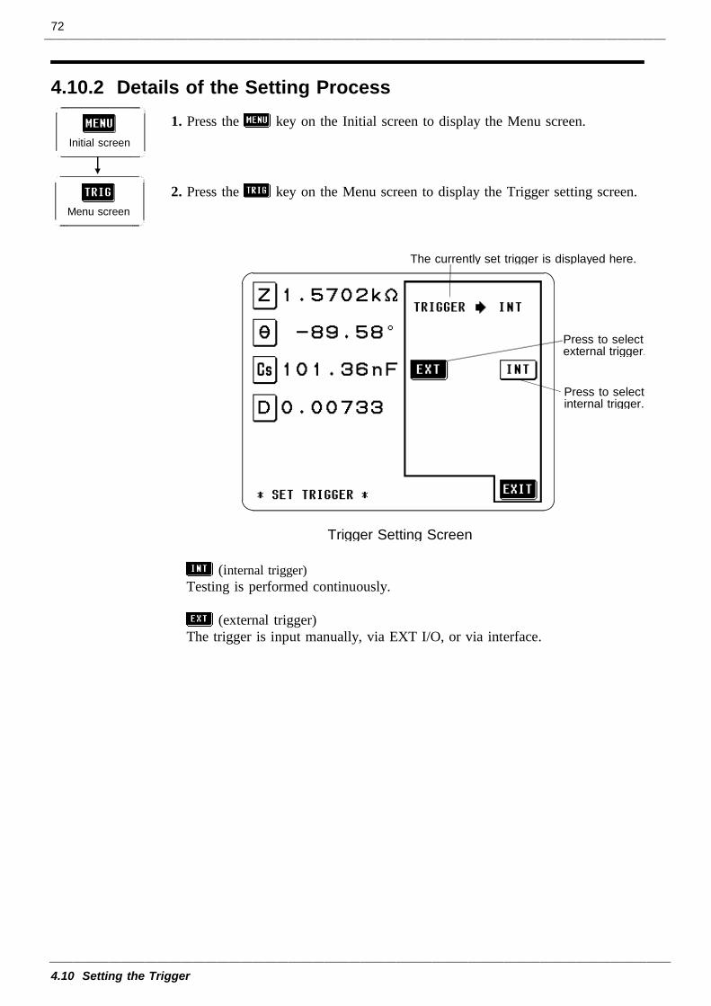
72
4.10 Setting the Trigger
4.10.2 Details of the Setting Process
Initial screen
Menu screen
Press to selectexternal trigger.
The currently set trigger is displayed here.
Press to selectinternal trigger.
Trigger Setting Screen
1. Press the key on the Initial screen to display the Menu screen.
2. Press the key on the Menu screen to display the Trigger setting screen.
(internal trigger)Testing is performed continuously.
(external trigger)The trigger is input manually, via EXT I/O, or via interface.
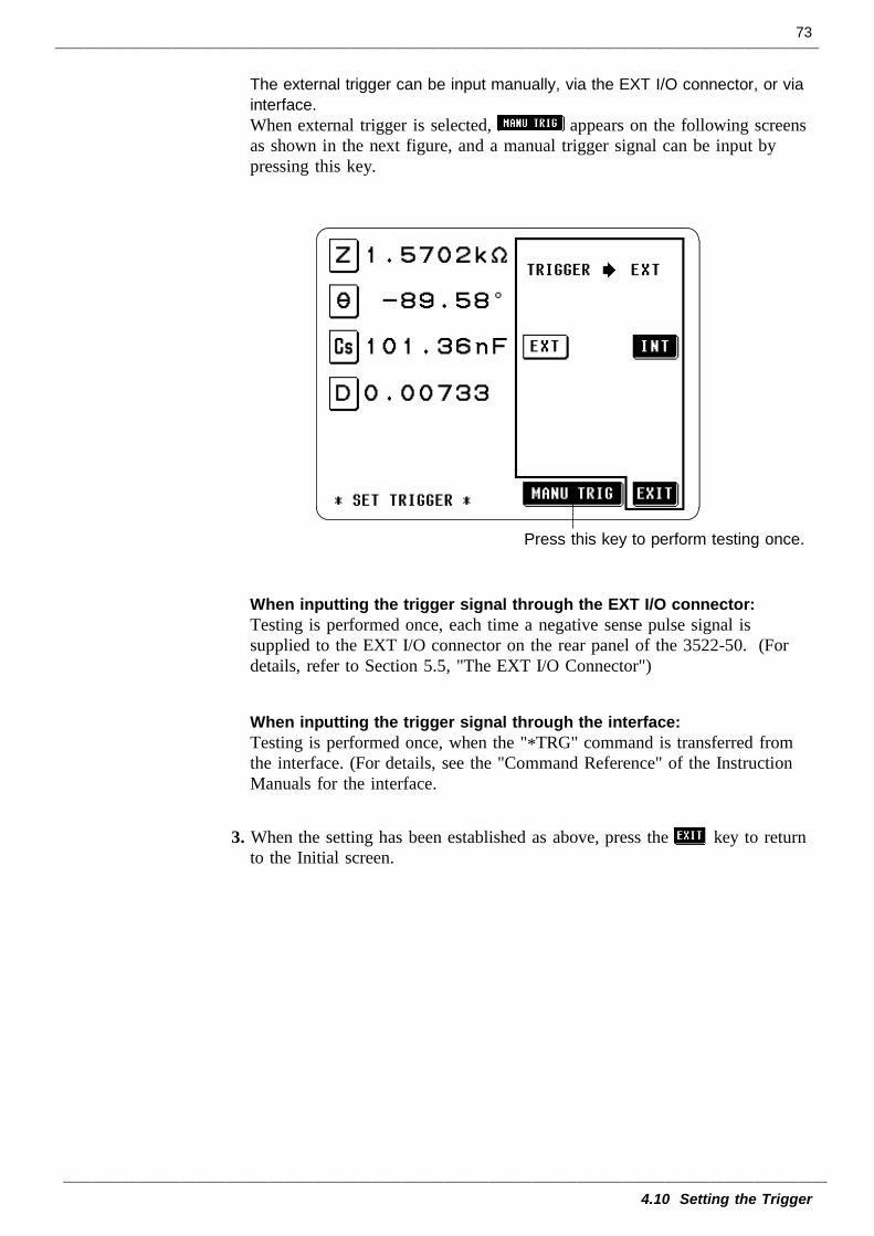
73
4.10 Setting the Trigger
Press this key to perform testing once.
The external trigger can be input manually, via the EXT I/O connector, or viainterface.When external trigger is selected, appears on the following screensas shown in the next figure, and a manual trigger signal can be input bypressing this key.
When inputting the trigger signal through the EXT I/O connector:Testing is performed once, each time a negative sense pulse signal issupplied to the EXT I/O connector on the rear panel of the 3522-50. (Fordetails, refer to Section 5.5, "The EXT I/O Connector")
When inputting the trigger signal through the interface:Testing is performed once, when the "*TRG" command is transferred fromthe interface. (For details, see the "Command Reference" of the InstructionManuals for the interface.
3. When the setting has been established as above, press the key to returnto the Initial screen.
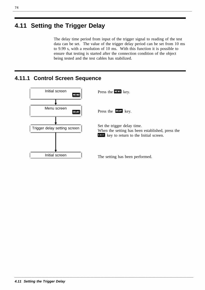
74
4.11 Setting the Trigger Delay
4.11.1 Control Screen Sequence
Trigger delay setting screen
Initial screen
Initial screen
Menu screen
4.11 Setting the Trigger Delay
The delay time period from input of the trigger signal to reading of the testdata can be set. The value of the trigger delay period can be set from 10 msto 9.99 s, with a resolution of 10 ms. With this function it is possible toensure that testing is started after the connection condition of the objectbeing tested and the test cables has stabilized.
Press the key.
Press the key.
Set the trigger delay time.When the setting has been established, press the
key to return to the Initial screen.
The setting has been performed.
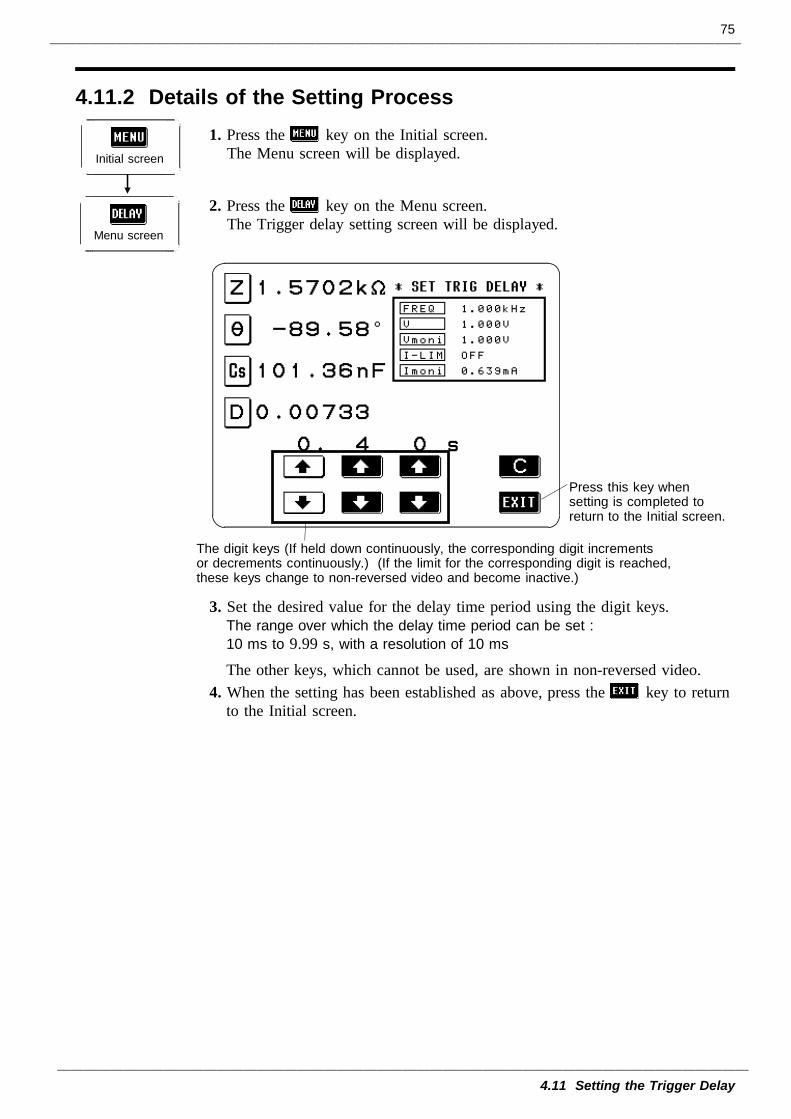
75
4.11 Setting the Trigger Delay
4.11.2 Details of the Setting Process
Initial screen
Menu screen
The digit keys (If held down continuously, the corresponding digit incrementsor decrements continuously.) (If the limit for the corresponding digit is reached,these keys change to non-reversed video and become inactive.)
Press this key whensetting is completed toreturn to the Initial screen.
1. Press the key on the Initial screen.The Menu screen will be displayed.
2. Press the key on the Menu screen.The Trigger delay setting screen will be displayed.
3. Set the desired value for the delay time period using the digit keys.The range over which the delay time period can be set :10 ms to 9.99 s, with a resolution of 10 ms
The other keys, which cannot be used, are shown in non-reversed video.4. When the setting has been established as above, press the key to return
to the Initial screen.
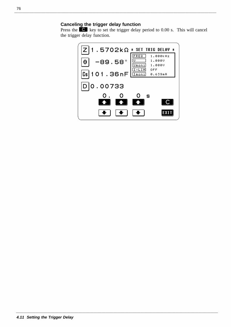
76
4.11 Setting the Trigger Delay
Canceling the trigger delay functionPress the key to set the trigger delay period to 0.00 s. This will cancelthe trigger delay function.
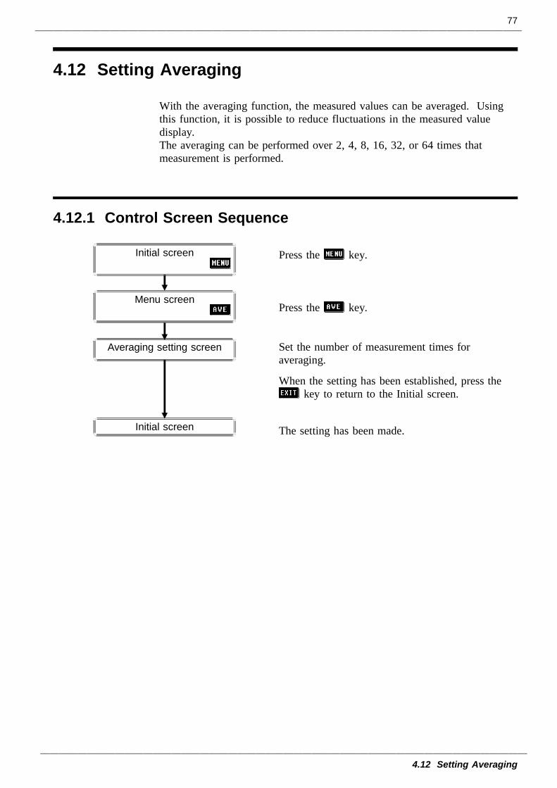
77
4.12 Setting Averaging
4.12.1 Control Screen Sequence
Averaging setting screen
Initial screen
Initial screen
Menu screen
4.12 Setting Averaging
With the averaging function, the measured values can be averaged. Usingthis function, it is possible to reduce fluctuations in the measured valuedisplay.The averaging can be performed over 2, 4, 8, 16, 32, or 64 times thatmeasurement is performed.
Press the key.
Press the key.
Set the number of measurement times foraveraging.
When the setting has been established, press thekey to return to the Initial screen.
The setting has been made.
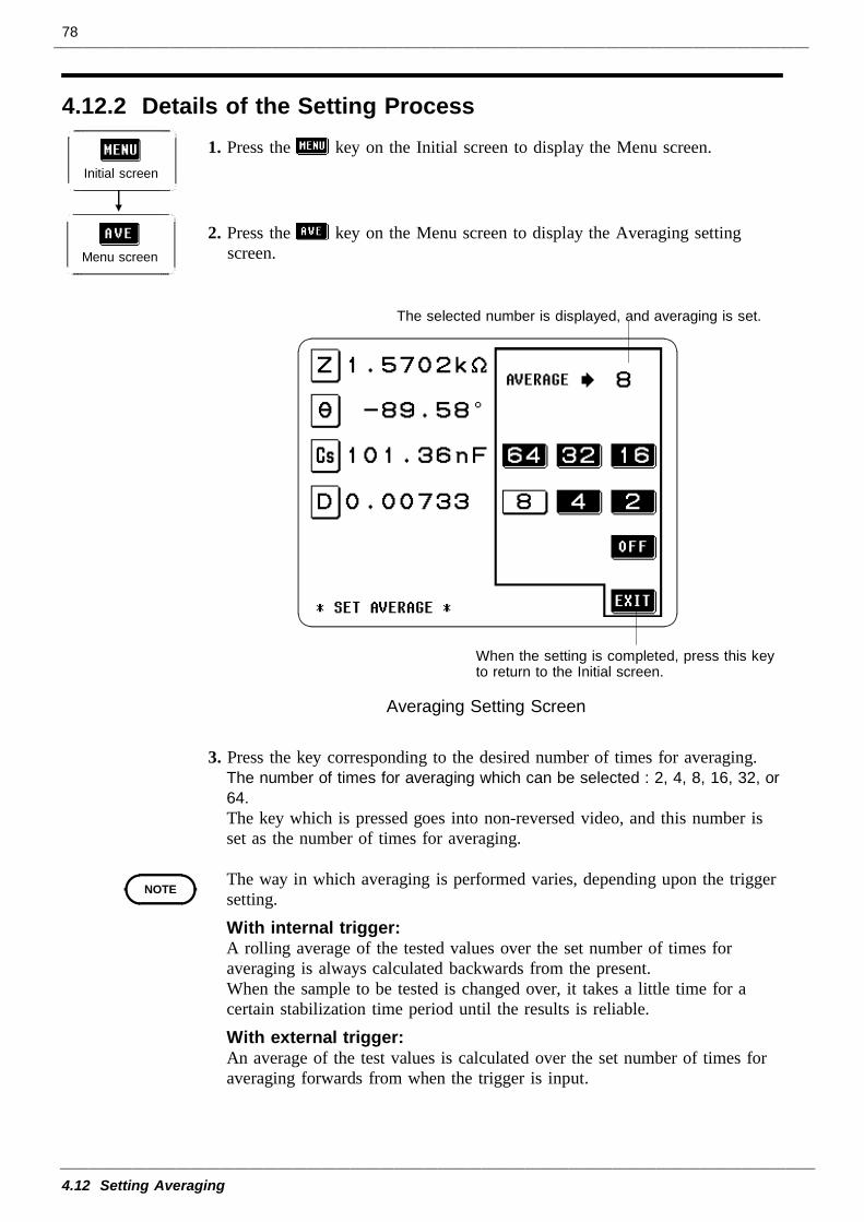
78
4.12 Setting Averaging
4.12.2 Details of the Setting Process
Initial screen
Menu screen
The selected number is displayed, and averaging is set.
When the setting is completed, press this keyto return to the Initial screen.
Averaging Setting Screen
NOTE
1. Press the key on the Initial screen to display the Menu screen.
2. Press the key on the Menu screen to display the Averaging settingscreen.
3. Press the key corresponding to the desired number of times for averaging.The number of times for averaging which can be selected : 2, 4, 8, 16, 32, or64.The key which is pressed goes into non-reversed video, and this number isset as the number of times for averaging.
The way in which averaging is performed varies, depending upon the triggersetting.With internal trigger:A rolling average of the tested values over the set number of times foraveraging is always calculated backwards from the present.When the sample to be tested is changed over, it takes a little time for acertain stabilization time period until the results is reliable.With external trigger:An average of the test values is calculated over the set number of times foraveraging forwards from when the trigger is input.
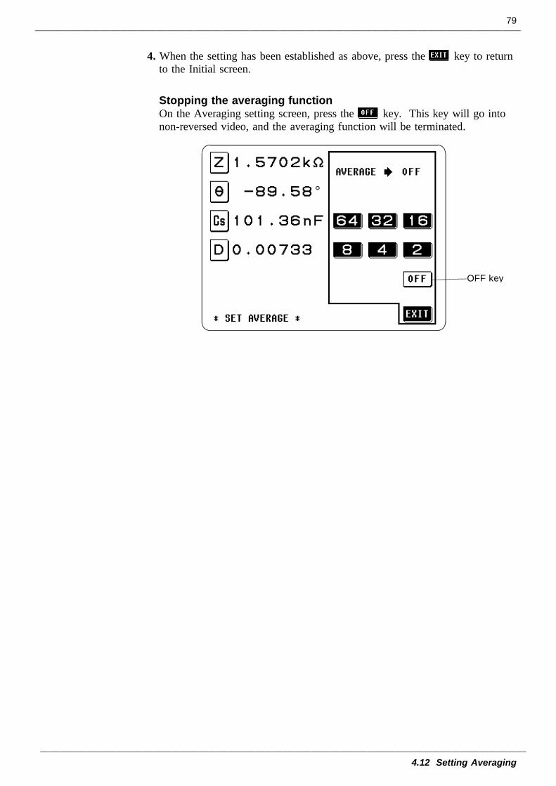
79
4.12 Setting Averaging
OFF key
4. When the setting has been established as above, press the key to returnto the Initial screen.
Stopping the averaging functionOn the Averaging setting screen, press the key. This key will go intonon-reversed video, and the averaging function will be terminated.
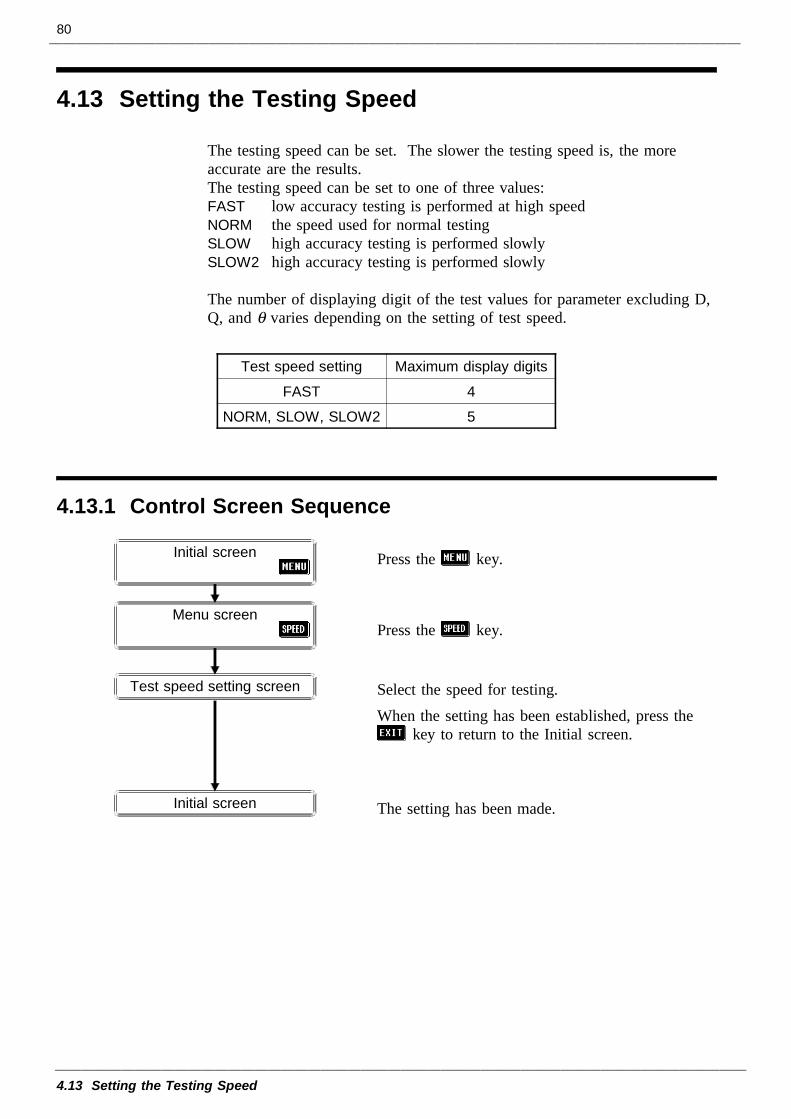
80
4.13 Setting the Testing Speed
Test speed setting Maximum display digits
FAST 4
NORM, SLOW, SLOW2 5
4.13.1 Control Screen Sequence
Initial screen
Initial screen
Menu screen
Test speed setting screen
4.13 Setting the Testing Speed
The testing speed can be set. The slower the testing speed is, the moreaccurate are the results.The testing speed can be set to one of three values:FAST low accuracy testing is performed at high speedNORM the speed used for normal testingSLOW high accuracy testing is performed slowlySLOW2 high accuracy testing is performed slowly
The number of displaying digit of the test values for parameter excluding D,Q, and θ varies depending on the setting of test speed.
Press the key.
Press the key.
Select the speed for testing.When the setting has been established, press the
key to return to the Initial screen.
The setting has been made.
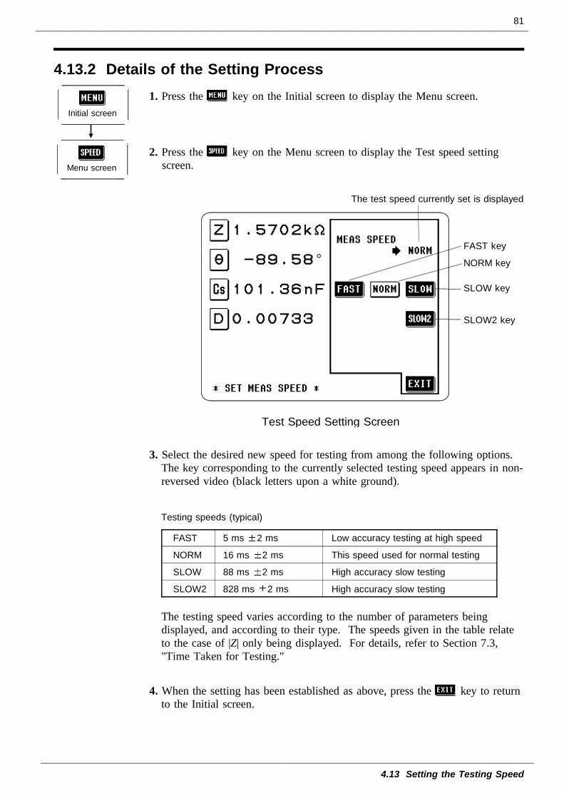
81
4.13 Setting the Testing Speed
4.13.2 Details of the Setting Process
Initial screen
Menu screen
The test speed currently set is displayed.
FAST key
NORM key
SLOW key
SLOW2 key
Test Speed Setting Screen
Testing speeds (typical)
FAST 5 ms 2 ms Low accuracy testing at high speed
NORM 16 ms 2 ms This speed used for normal testing
SLOW 88 ms 2 ms High accuracy slow testing
SLOW2 828 ms 2 ms High accuracy slow testing
1. Press the key on the Initial screen to display the Menu screen.
2. Press the key on the Menu screen to display the Test speed settingscreen.
3. Select the desired new speed for testing from among the following options.The key corresponding to the currently selected testing speed appears in non-reversed video (black letters upon a white ground).
The testing speed varies according to the number of parameters beingdisplayed, and according to their type. The speeds given in the table relateto the case of |Z| only being displayed. For details, refer to Section 7.3,"Time Taken for Testing."
4. When the setting has been established as above, press the key to returnto the Initial screen.
82
4.14 Setting and Activating the Comparator
4.14 Setting and Activating the ComparatorUsing the comparator function an upper limit value and a lower limit valuecan be set, and the result of measurement then can be compared with thesetwo limit values, so as to give a result expressed as HI (greater than theupper limit value), IN (between the lower limit value and the upper limitvalue), or LO (less than the lower limit value). Moreover, a correspondingsignal can be output via the EXT I/O connector on the rear panel of the3522-50 unit.The following setting methods are available on the comparator:Absolute value setting method (ABS)The upper limit value and the lower limit value are set as absolute numericalvalues. The measurement values displayed are the same as those of themeasurement parameters.Percentage setting method (%)A reference value is input, and the upper-limit and lower-limit values are setas percentages relative to the reference value. The measurement valuesdisplayed are the same as those of the measurement parameters.Setting of the deviation percentage (∆%)A reference value is input, and the upper-limit and lower-limit values are setas percentages relative to the reference value. The measurement values aredisplayed in deviations (∆%) from the reference value.
The comparator can deal with two test values at the most. "ABS", "%", and"∆%" can be selected for each of these values individually.After powering off on the Comparator setting screen, the screen is displayedwhen the power is turned on again.
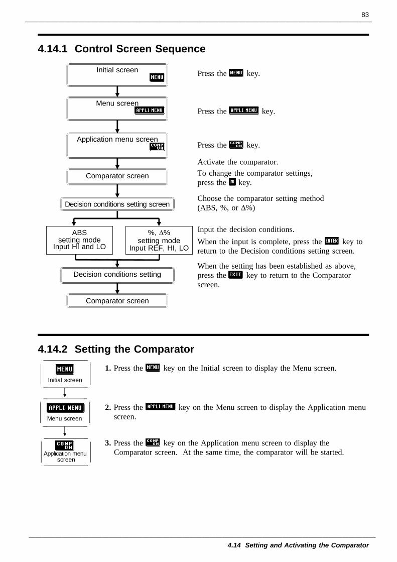
83
4.14 Setting and Activating the Comparator
4.14.1 Control Screen Sequence
Comparator screen
Comparator screen
Initial screen
Menu screen
Application menu screen
ABSsetting mode
Input HI and LO
%, ∆%setting mode
Input REF, HI, LO
Decision conditions setting screen
Decision conditions setting
4.14.2 Setting the Comparator
Initial screen
Application menuscreen
Menu screen
Press the key.
Press the key.
Press the key.
Activate the comparator.To change the comparator settings,press the key.
Choose the comparator setting method(ABS, %, or ∆%)
Input the decision conditions.When the input is complete, press the key toreturn to the Decision conditions setting screen.
When the setting has been established as above,press the key to return to the Comparatorscreen.
1. Press the key on the Initial screen to display the Menu screen.
2. Press the key on the Menu screen to display the Application menuscreen.
3. Press the key on the Application menu screen to display theComparator screen. At the same time, the comparator will be started.
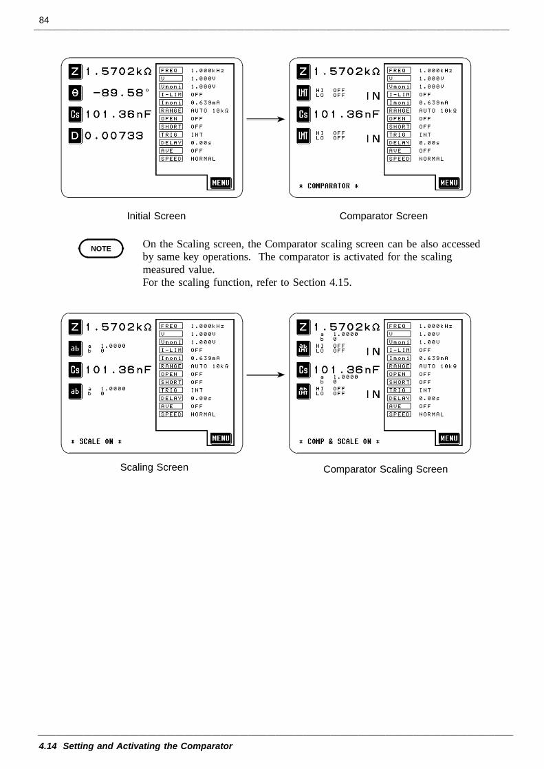
84
4.14 Setting and Activating the Comparator
Initial Screen Comparator Screen
NOTE
Scaling Screen Comparator Scaling Screen
On the Scaling screen, the Comparator scaling screen can be also accessedby same key operations. The comparator is activated for the scalingmeasured value.For the scaling function, refer to Section 4.15.
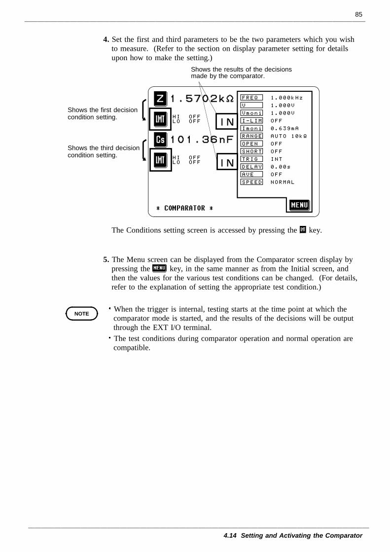
85
4.14 Setting and Activating the Comparator
Shows the results of the decisionsmade by the comparator.
Shows the first decisioncondition setting.
Shows the third decisioncondition setting.
NOTE
4. Set the first and third parameters to be the two parameters which you wishto measure. (Refer to the section on display parameter setting for detailsupon how to make the setting.)
The Conditions setting screen is accessed by pressing the key.
5. The Menu screen can be displayed from the Comparator screen display bypressing the key, in the same manner as from the Initial screen, andthen the values for the various test conditions can be changed. (For details,refer to the explanation of setting the appropriate test condition.)
When the trigger is internal, testing starts at the time point at which thecomparator mode is started, and the results of the decisions will be outputthrough the EXT I/O terminal.The test conditions during comparator operation and normal operation arecompatible.
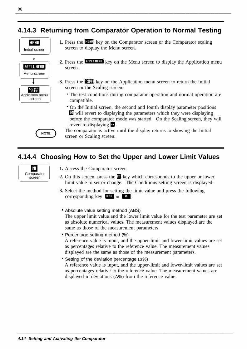
86
4.14 Setting and Activating the Comparator
4.14.3 Returning from Comparator Operation to Normal Testing
Initial screen
Menu screen
Application menuscreen
NOTE
4.14.4 Choosing How to Set the Upper and Lower Limit Values
Comparatorscreen
1. Press the key on the Comparator screen or the Comparator scalingscreen to display the Menu screen.
2. Press the key on the Menu screen to display the Application menuscreen.
3. Press the key on the Application menu screen to return the Initialscreen or the Scaling screen.
The test conditions during comparator operation and normal operation arecompatible.On the Initial screen, the second and fourth display parameter positions
will revert to displaying the parameters which they were displayingbefore the comparator mode was started. On the Scaling screen, they willrevert to displaying .
The comparator is active until the display returns to showing the Initialscreen or Scaling screen.
1. Access the Comparator screen.2. On this screen, press the key which corresponds to the upper or lower
limit value to set or change. The Conditions setting screen is displayed.3. Select the method for setting the limit value and press the following
corresponding key or :
Absolute value setting method (ABS)The upper limit value and the lower limit value for the test parameter are setas absolute numerical values. The measurement values displayed are thesame as those of the measurement parameters.Percentage setting method (%)A reference value is input, and the upper-limit and lower-limit values are setas percentages relative to the reference value. The measurement valuesdisplayed are the same as those of the measurement parameters.Setting of the deviation percentage (∆%)A reference value is input, and the upper-limit and lower-limit values are setas percentages relative to the reference value. The measurement values aredisplayed in deviations (∆%) from the reference value.
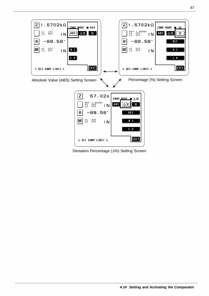
87
4.14 Setting and Activating the Comparator
Absolute Value (ABS) Setting Screen Percentage (%) Setting Screen
Deviation Percentage (∆%) Setting Screen
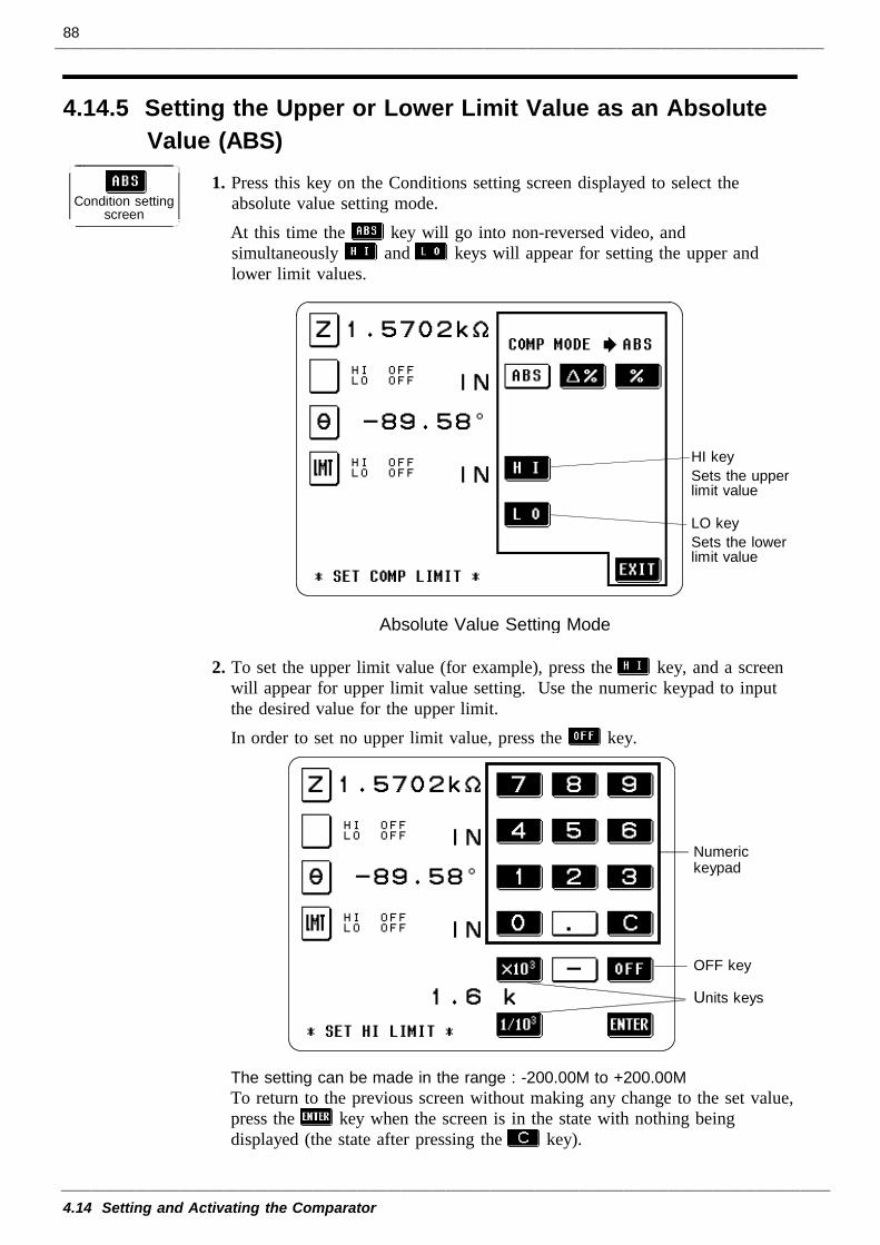
88
4.14 Setting and Activating the Comparator
4.14.5 Setting the Upper or Lower Limit Value as an AbsoluteValue (ABS)
Condition settingscreen
HI keySets the upperlimit value
LO keySets the lowerlimit value
Absolute Value Setting Mode
Numerickeypad
OFF key
Units keys
1. Press this key on the Conditions setting screen displayed to select theabsolute value setting mode.At this time the key will go into non-reversed video, andsimultaneously and keys will appear for setting the upper andlower limit values.
2. To set the upper limit value (for example), press the key, and a screenwill appear for upper limit value setting. Use the numeric keypad to inputthe desired value for the upper limit.In order to set no upper limit value, press the key.
The setting can be made in the range : -200.00M to +200.00MTo return to the previous screen without making any change to the set value,press the key when the screen is in the state with nothing beingdisplayed (the state after pressing the key).
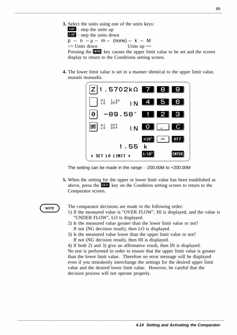
89
4.14 Setting and Activating the Comparator
NOTE
3. Select the units using one of the units keys:: step the units up: step the units down
p -- n -- µ -- m -- (none) -- k -- M<= Units down Units up =>Pressing the key causes the upper limit value to be set and the screendisplay to return to the Conditions setting screen.
4. The lower limit value is set in a manner identical to the upper limit value,mutatis mutandis.
The setting can be made in the range : -200.00M to +200.00M
5. When the setting for the upper or lower limit value has been established asabove, press the key on the Condition setting screen to return to theComparator screen.
The comparator decisions are made in the following order:1) If the measured value is "OVER FLOW", HI is displayed, and the value is
"UNDER FLOW", LO is displayed.2) Is the measured value greater than the lower limit value or not?
If not (NG decision result), then LO is displayed.3) Is the measured value lower than the upper limit value or not?
If not (NG decision result), then HI is displayed.4) If both 2) and 3) give an affirmative result, then IN is displayed.No test is performed in order to ensure that the upper limit value is greaterthan the lower limit value. Therefore no error message will be displayedeven if you mistakenly interchange the settings for the desired upper limitvalue and the desired lower limit value. However, be careful that thedecision process will not operate properly.
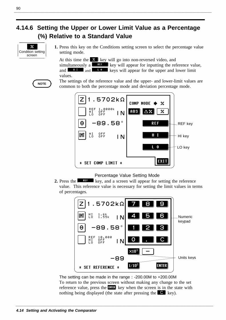
90
4.14 Setting and Activating the Comparator
4.14.6 Setting the Upper or Lower Limit Value as a Percentage(%) Relative to a Standard Value
Condition settingscreen
NOTE
REF key
HI key
LO key
Percentage Value Setting Mode
Numerickeypad
Units keys
1. Press this key on the Conditions setting screen to select the percentage valuesetting mode.At this time the key will go into non-reversed video, andsimultaneously a key will appear for inputting the reference value,and and keys will appear for the upper and lower limitvalues.The settings of the reference value and the upper- and lower-limit values arecommon to both the percentage mode and deviation percentage mode.
2. Press the key, and a screen will appear for setting the referencevalue. This reference value is necessary for setting the limit values in termsof percentages.
The setting can be made in the range : -200.00M to +200.00MTo return to the previous screen without making any change to the setreference value, press the key when the screen is in the state withnothing being displayed (the state after pressing the key).
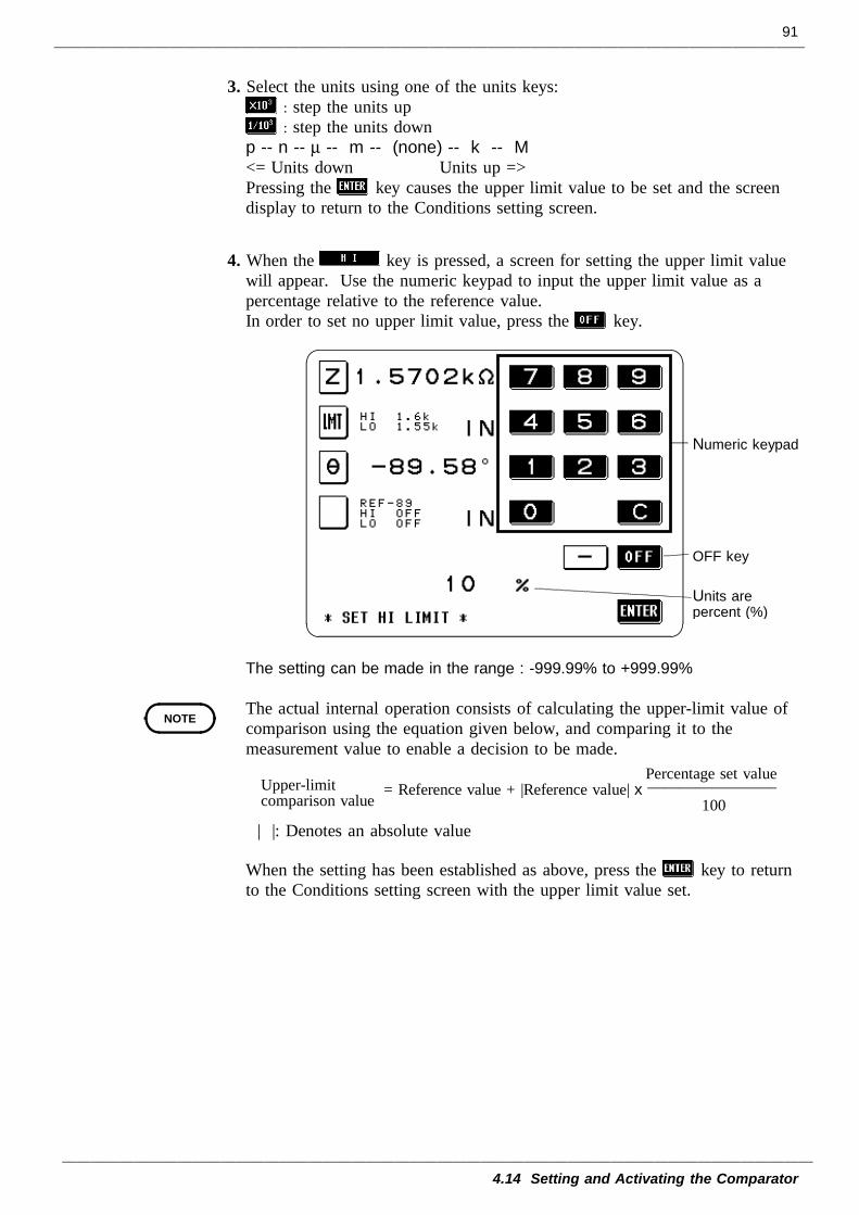
91
4.14 Setting and Activating the Comparator
Numeric keypad
OFF key
Units arepercent (%)
NOTE
Percentage set value= Reference value + |Reference value| x ________________ 100
Upper-limitcomparison value
3. Select the units using one of the units keys:: step the units up: step the units down
p -- n -- µ -- m -- (none) -- k -- M<= Units down Units up =>Pressing the key causes the upper limit value to be set and the screendisplay to return to the Conditions setting screen.
4. When the key is pressed, a screen for setting the upper limit valuewill appear. Use the numeric keypad to input the upper limit value as apercentage relative to the reference value.In order to set no upper limit value, press the key.
The setting can be made in the range : -999.99% to +999.99%
The actual internal operation consists of calculating the upper-limit value ofcomparison using the equation given below, and comparing it to themeasurement value to enable a decision to be made.
| |: Denotes an absolute value
When the setting has been established as above, press the key to returnto the Conditions setting screen with the upper limit value set.
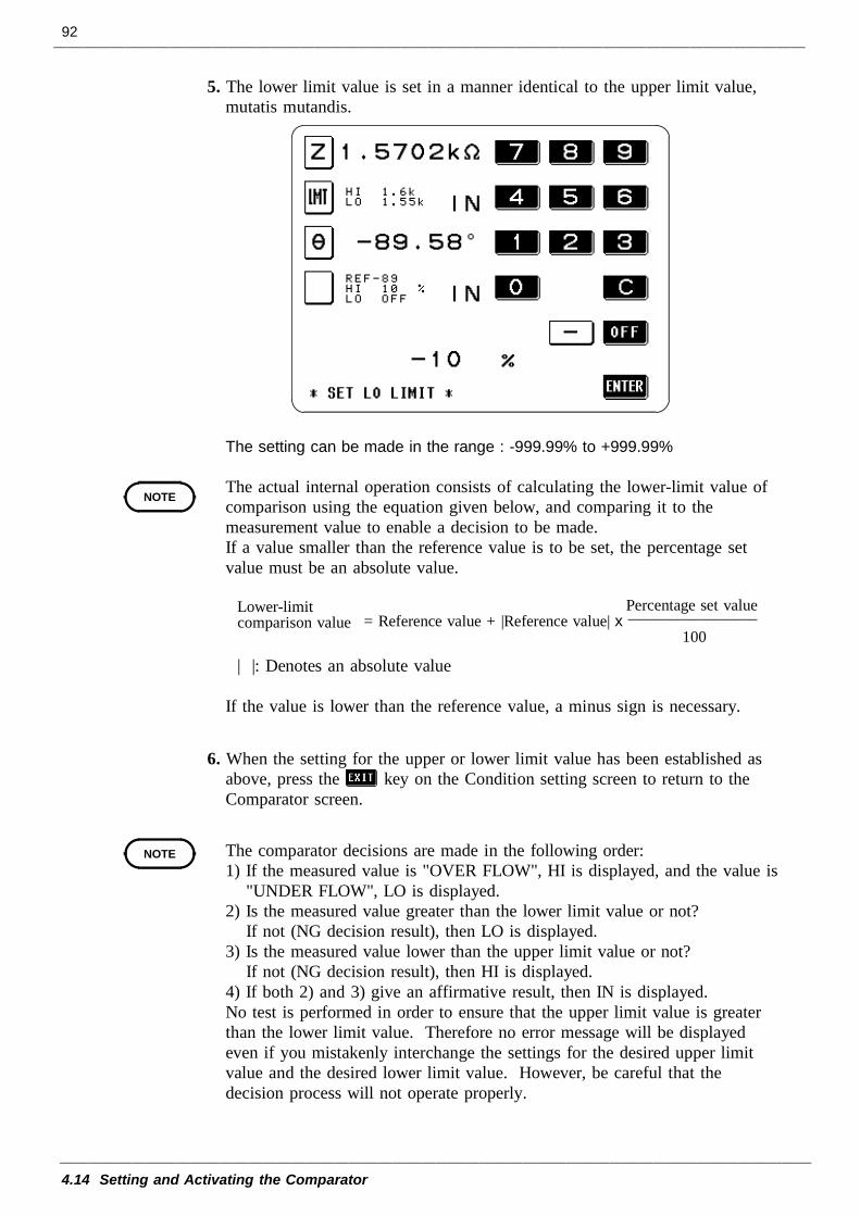
92
4.14 Setting and Activating the Comparator
NOTE
Lower-limitcomparison value
Percentage set value= Reference value + |Reference value| x ________________ 100
NOTE
5. The lower limit value is set in a manner identical to the upper limit value,mutatis mutandis.
The setting can be made in the range : -999.99% to +999.99%
The actual internal operation consists of calculating the lower-limit value ofcomparison using the equation given below, and comparing it to themeasurement value to enable a decision to be made.If a value smaller than the reference value is to be set, the percentage setvalue must be an absolute value.
| |: Denotes an absolute value
If the value is lower than the reference value, a minus sign is necessary.
6. When the setting for the upper or lower limit value has been established asabove, press the key on the Condition setting screen to return to theComparator screen.
The comparator decisions are made in the following order:1) If the measured value is "OVER FLOW", HI is displayed, and the value is
"UNDER FLOW", LO is displayed.2) Is the measured value greater than the lower limit value or not?
If not (NG decision result), then LO is displayed.3) Is the measured value lower than the upper limit value or not?
If not (NG decision result), then HI is displayed.4) If both 2) and 3) give an affirmative result, then IN is displayed.No test is performed in order to ensure that the upper limit value is greaterthan the lower limit value. Therefore no error message will be displayedeven if you mistakenly interchange the settings for the desired upper limitvalue and the desired lower limit value. However, be careful that thedecision process will not operate properly.
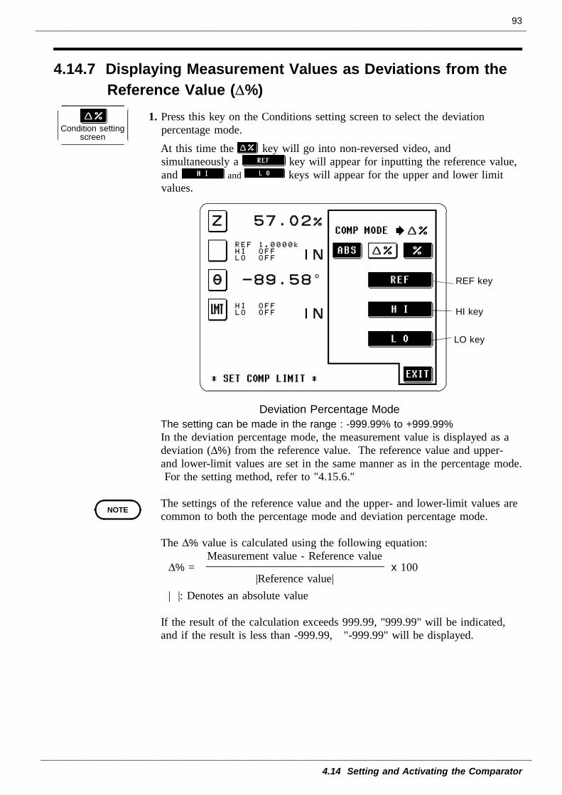
93
4.14 Setting and Activating the Comparator
4.14.7 Displaying Measurement Values as Deviations from theReference Value (∆%)
Condition settingscreen
REF key
HI key
LO key
Deviation Percentage Mode
NOTE
1. Press this key on the Conditions setting screen to select the deviationpercentage mode.At this time the key will go into non-reversed video, andsimultaneously a key will appear for inputting the reference value,and and keys will appear for the upper and lower limitvalues.
The setting can be made in the range : -999.99% to +999.99%In the deviation percentage mode, the measurement value is displayed as adeviation (∆%) from the reference value. The reference value and upper-and lower-limit values are set in the same manner as in the percentage mode.For the setting method, refer to "4.15.6."
The settings of the reference value and the upper- and lower-limit values arecommon to both the percentage mode and deviation percentage mode.
The ∆% value is calculated using the following equation: Measurement value - Reference value
∆% = _______________________________ x 100 |Reference value|
| |: Denotes an absolute value
If the result of the calculation exceeds 999.99, "999.99" will be indicated,and if the result is less than -999.99, "-999.99" will be displayed.
94
4.14 Setting and Activating the Comparator
NOTEThe comparator decisions are made in the following order:1) If the measured value is "OVER FLOW", HI is displayed, and the value is
"UNDER FLOW", LO is displayed.2) Is the measured value greater than the lower limit value or not?
If not (NG decision result), then LO is displayed.3) Is the measured value lower than the upper limit value or not?
If not (NG decision result), then HI is displayed.4) If both 2) and 3) give an affirmative result, then IN is displayed.No test is performed in order to ensure that the upper limit value is greaterthan the lower limit value. Therefore no error message will be displayedeven if you mistakenly interchange the settings for the desired upper limitvalue and the desired lower limit value. However, be careful that thedecision process will not operate properly.
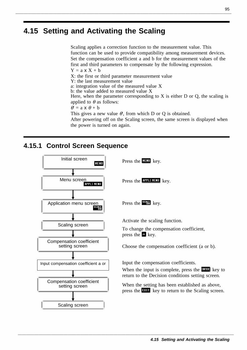
95
4.15 Setting and Activating the Scaling
4.15.1 Control Screen Sequence
Scaling screen
Scaling screen
Initial screen
Menu screen
Application menu screen
Input compensation coefficient a or
Compensation coefficientsetting screen
Compensation coefficientsetting screen
4.15 Setting and Activating the Scaling
Scaling applies a correction function to the measurement value. Thisfunction can be used to provide compatibility among measurement devices.Set the compensation coefficient a and b for the measurement values of thefirst and third parameters to compensate by the following expression.Y = a x X + bX: the first or third parameter measurement valueY: the last measurement valuea: integration value of the measured value Xb: the value added to measured value XHere, when the parameter corresponding to X is either D or Q, the scaling isapplied to θ as follows:θ' = a x θ + bThis gives a new value θ', from which D or Q is obtained.After powering off on the Scaling screen, the same screen is displayed whenthe power is turned on again.
Press the key.
Press the key.
Press the key.
Activate the scaling function.To change the compensation coefficient,press the key.
Choose the compensation coefficient (a or b).
Input the compensation coefficients.When the input is complete, press the key toreturn to the Decision conditions setting screen.
When the setting has been established as above,press the key to return to the Scaling screen.
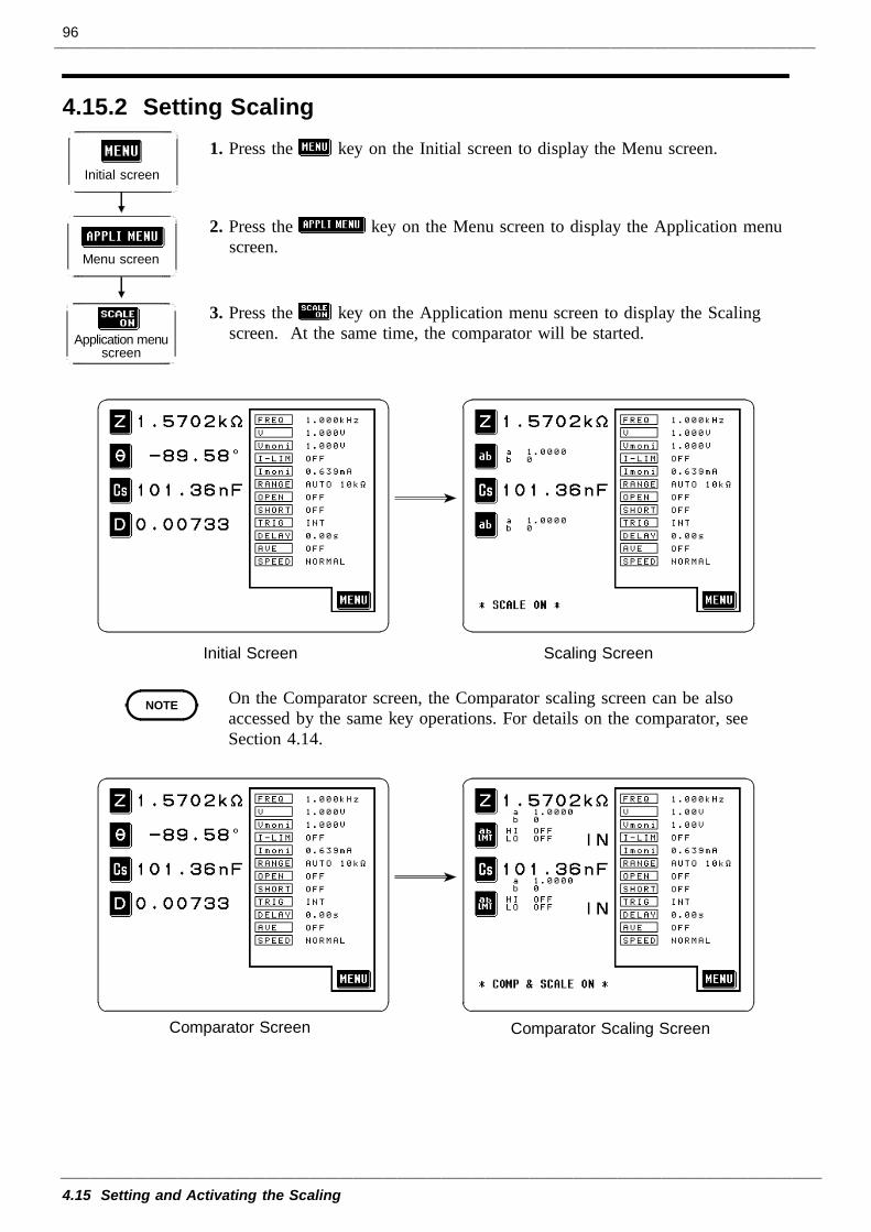
96
4.15 Setting and Activating the Scaling
4.15.2 Setting Scaling
Initial screen
Menu screen
Application menuscreen
Initial Screen Scaling Screen
NOTE
Comparator Screen Comparator Scaling Screen
1. Press the key on the Initial screen to display the Menu screen.
2. Press the key on the Menu screen to display the Application menuscreen.
3. Press the key on the Application menu screen to display the Scalingscreen. At the same time, the comparator will be started.
On the Comparator screen, the Comparator scaling screen can be alsoaccessed by the same key operations. For details on the comparator, seeSection 4.14.
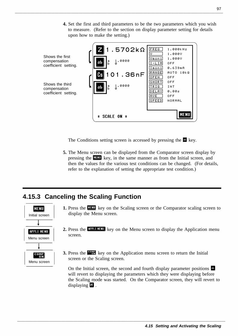
97
4.15 Setting and Activating the Scaling
Shows the firstcompensationcoefficient setting.
Shows the thirdcompensationcoefficient setting.
4.15.3 Canceling the Scaling Function
Initial screen
Menu screen
Menu screen
4. Set the first and third parameters to be the two parameters which you wishto measure. (Refer to the section on display parameter setting for detailsupon how to make the setting.)
The Conditions setting screen is accessed by pressing the key.
5. The Menu screen can be displayed from the Comparator screen display bypressing the key, in the same manner as from the Initial screen, andthen the values for the various test conditions can be changed. (For details,refer to the explanation of setting the appropriate test condition.)
1. Press the key on the Scaling screen or the Comparator scaling screen todisplay the Menu screen.
2. Press the key on the Menu screen to display the Application menuscreen.
3. Press the key on the Application menu screen to return the Initialscreen or the Scaling screen.
On the Initial screen, the second and fourth display parameter positionswill revert to displaying the parameters which they were displaying beforethe Scaling mode was started. On the Comparator screen, they will revert todisplaying .
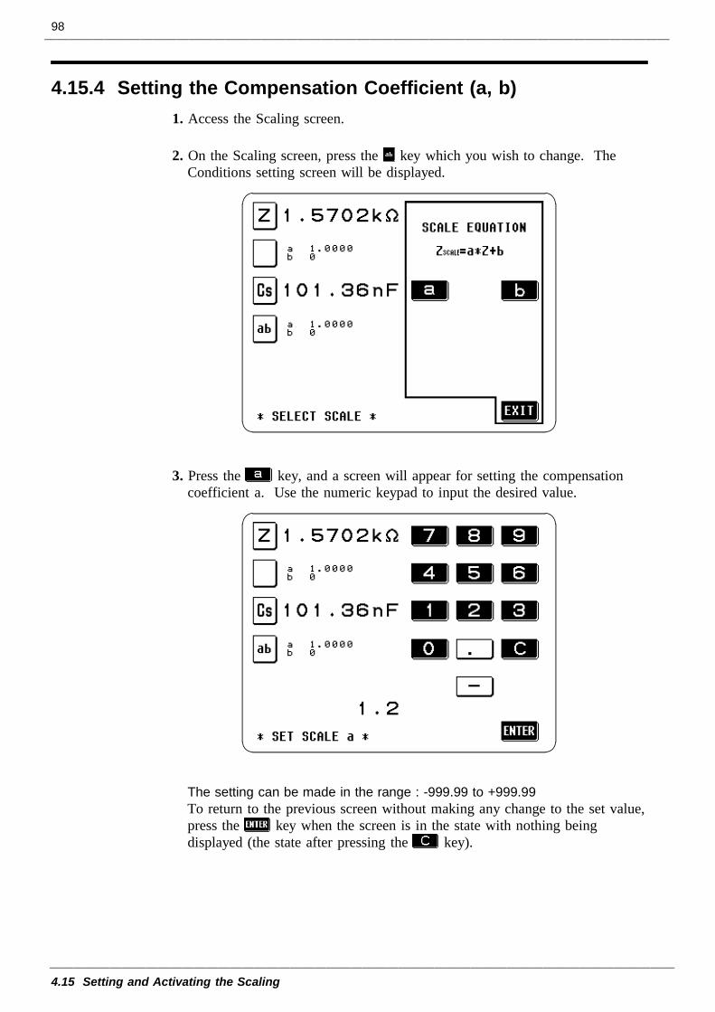
98
4.15 Setting and Activating the Scaling
4.15.4 Setting the Compensation Coefficient (a, b)1. Access the Scaling screen.
2. On the Scaling screen, press the key which you wish to change. TheConditions setting screen will be displayed.
3. Press the key, and a screen will appear for setting the compensationcoefficient a. Use the numeric keypad to input the desired value.
The setting can be made in the range : -999.99 to +999.99To return to the previous screen without making any change to the set value,press the key when the screen is in the state with nothing beingdisplayed (the state after pressing the key).
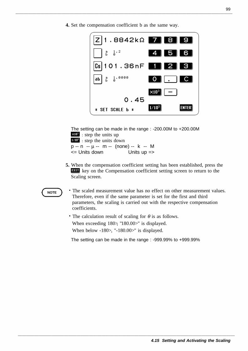
99
4.15 Setting and Activating the Scaling
NOTE
4. Set the compensation coefficient b as the same way.
The setting can be made in the range : -200.00M to +200.00M: step the units up: step the units down
p -- n -- µ -- m -- (none) -- k -- M<= Units down Units up =>
5. When the compensation coefficient setting has been established, press thekey on the Compensation coefficient setting screen to return to the
Scaling screen.
The scaled measurement value has no effect on other measurement values.Therefore, even if the same parameter is set for the first and thirdparameters, the scaling is carried out with the respective compensationcoefficients.The calculation result of scaling for θ is as follows.When exceeding 180°, "180.00°" is displayed.When below -180°, "-180.00°" is displayed.
The setting can be made in the range : -999.99% to +999.99%
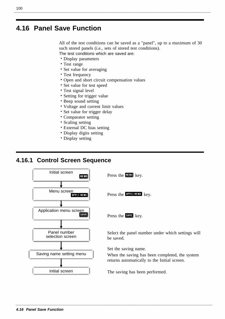
100
4.16 Panel Save Function
4.16.1 Control Screen Sequence
Initial screen
Panel numberselection screen
Initial screen
Menu screen
Application menu screen
Saving name setting menu
4.16 Panel Save Function
All of the test conditions can be saved as a "panel", up to a maximum of 30such stored panels (i.e., sets of stored test conditions).The test conditions which are saved are:
Display parametersTest rangeSet value for averagingTest frequencyOpen and short circuit compensation valuesSet value for test speedTest signal levelSetting for trigger valueBeep sound settingVoltage and current limit valuesSet value for trigger delayComparator settingScaling settingExternal DC bias settingDisplay digits settingDisplay setting
Press the key.
Press the key.
Press the key.
Select the panel number under which settings willbe saved.
Set the saving name.When the saving has been completed, the systemreturns automatically to the Initial screen.
The saving has been performed.
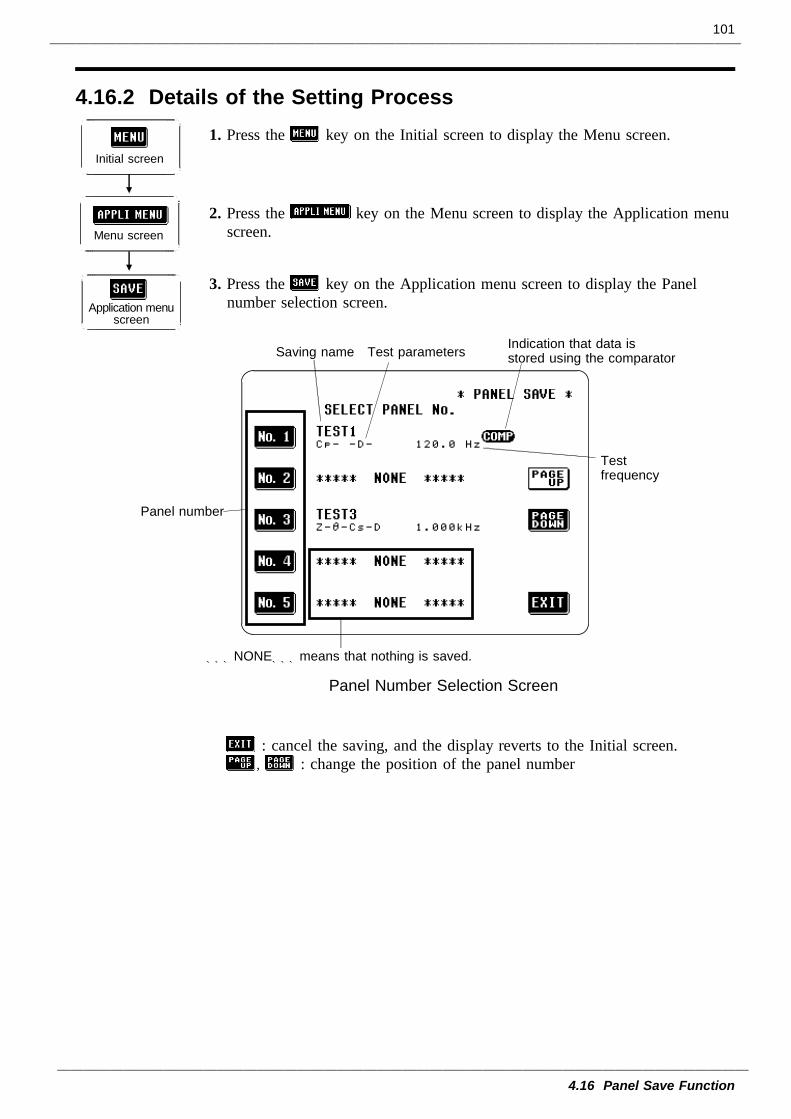
101
4.16 Panel Save Function
4.16.2 Details of the Setting Process
Initial screen
Application menuscreen
Menu screen
Panel number
Testfrequency
***NONE***means that nothing is saved.
Saving name Test parameters Indication that data isstored using the comparator
Panel Number Selection Screen
1. Press the key on the Initial screen to display the Menu screen.
2. Press the key on the Menu screen to display the Application menuscreen.
3. Press the key on the Application menu screen to display the Panelnumber selection screen.
: cancel the saving, and the display reverts to the Initial screen., : change the position of the panel number
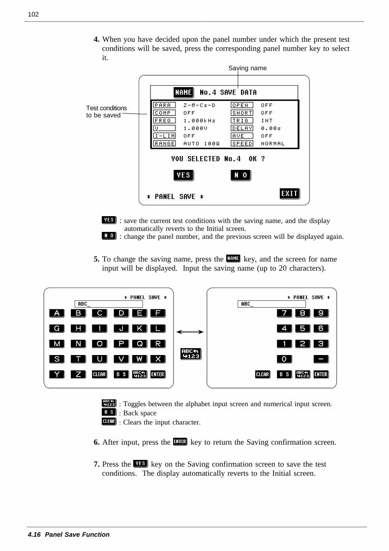
102
4.16 Panel Save Function
Saving name
Test conditionsto be saved
4. When you have decided upon the panel number under which the present testconditions will be saved, press the corresponding panel number key to selectit.
: save the current test conditions with the saving name, and the displayautomatically reverts to the Initial screen.
: change the panel number, and the previous screen will be displayed again.
5. To change the saving name, press the key, and the screen for nameinput will be displayed. Input the saving name (up to 20 characters).
: Toggles between the alphabet input screen and numerical input screen.: Back space: Clears the input character.
6. After input, press the key to return the Saving confirmation screen.
7. Press the key on the Saving confirmation screen to save the testconditions. The display automatically reverts to the Initial screen.
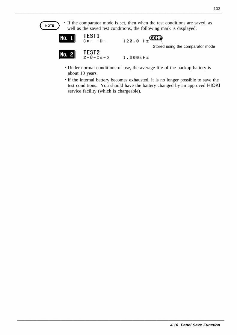
103
4.16 Panel Save Function
NOTE
Stored using the comparator mode
If the comparator mode is set, then when the test conditions are saved, aswell as the saved test conditions, the following mark is displayed:
Under normal conditions of use, the average life of the backup battery isabout 10 years.If the internal battery becomes exhausted, it is no longer possible to save thetest conditions. You should have the battery changed by an approved HIOKIservice facility (which is chargeable).
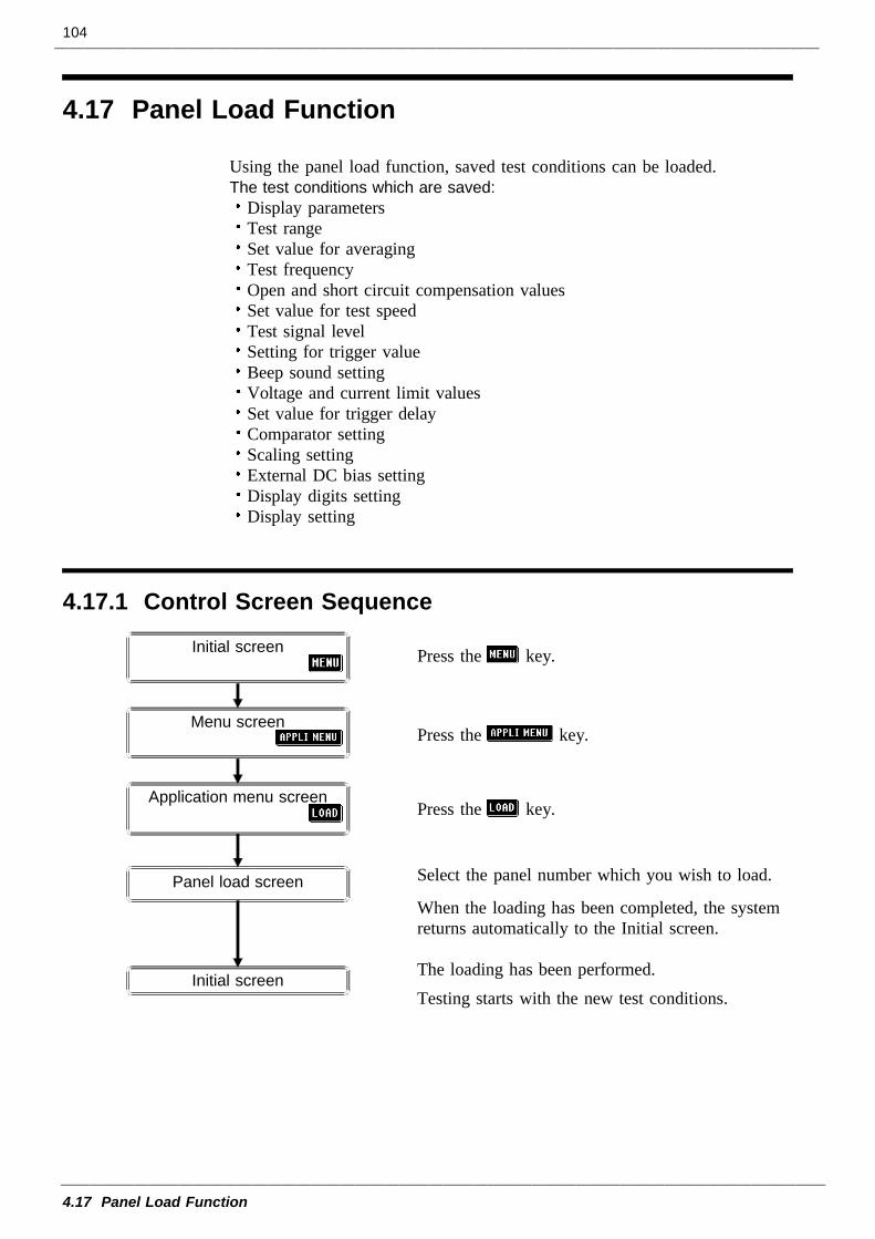
104
4.17 Panel Load Function
4.17.1 Control Screen Sequence
Panel load screen
Initial screen
Menu screen
Application menu screen
Initial screen
4.17 Panel Load Function
Using the panel load function, saved test conditions can be loaded.The test conditions which are saved:
Display parametersTest rangeSet value for averagingTest frequencyOpen and short circuit compensation valuesSet value for test speedTest signal levelSetting for trigger valueBeep sound settingVoltage and current limit valuesSet value for trigger delayComparator settingScaling settingExternal DC bias settingDisplay digits settingDisplay setting
Press the key.
Press the key.
Press the key.
Select the panel number which you wish to load.
When the loading has been completed, the systemreturns automatically to the Initial screen.
The loading has been performed.Testing starts with the new test conditions.
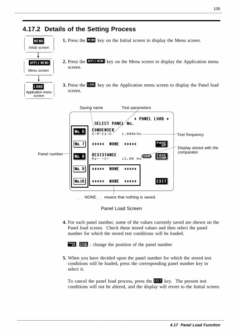
105
4.17 Panel Load Function
4.17.2 Details of the Setting Process
Application menuscreen
Initial screen
Menu screen
***NONE***means that nothing is saved.
Saving name Test parameters
Panel number
Test frequency
Display stored with thecomparator
Panel Load Screen
1. Press the key on the Initial screen to display the Menu screen.
2. Press the key on the Menu screen to display the Application menuscreen.
3. Press the key on the Application menu screen to display the Panel loadscreen.
4. For each panel number, some of the values currently saved are shown on thePanel load screen. Check these stored values and then select the panelnumber for which the stored test conditions will be loaded.
, : change the position of the panel number
5. When you have decided upon the panel number for which the stored testconditions will be loaded, press the corresponding panel number key toselect it.
To cancel the panel load process, press the key. The present testconditions will not be altered, and the display will revert to the Initial screen.
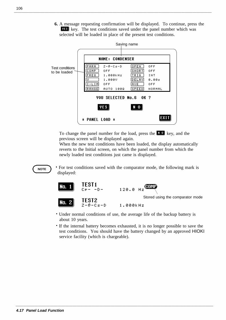
106
4.17 Panel Load Function
Saving name
Test conditionsto be loaded
NOTE
Stored using the comparator mode
6. A message requesting confirmation will be displayed. To continue, press thekey. The test conditions saved under the panel number which was
selected will be loaded in place of the present test conditions.
To change the panel number for the load, press the key, and theprevious screen will be displayed again.When the new test conditions have been loaded, the display automaticallyreverts to the Initial screen, on which the panel number from which thenewly loaded test conditions just came is displayed.
For test conditions saved with the comparator mode, the following mark isdisplayed:
Under normal conditions of use, the average life of the backup battery isabout 10 years.If the internal battery becomes exhausted, it is no longer possible to save thetest conditions. You should have the battery changed by an approved HIOKIservice facility (which is chargeable).
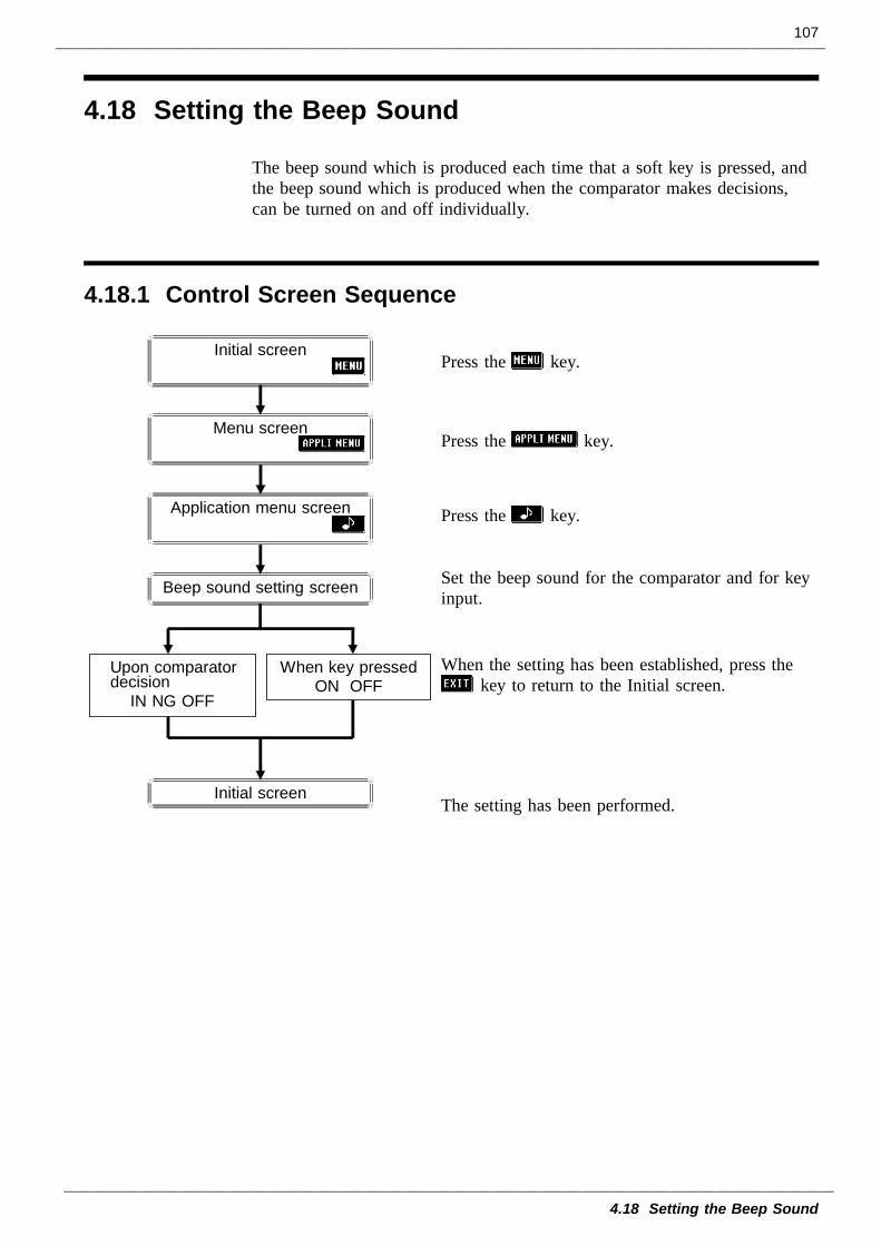
107
4.18 Setting the Beep Sound
4.18.1 Control Screen Sequence
Initial screen
Beep sound setting screen
Upon comparatordecision
IN NG OFF
When key pressedON OFF
Initial screen
Menu screen
Application menu screen
4.18 Setting the Beep Sound
The beep sound which is produced each time that a soft key is pressed, andthe beep sound which is produced when the comparator makes decisions,can be turned on and off individually.
Press the key.
Press the key.
Press the key.
Set the beep sound for the comparator and for keyinput.
When the setting has been established, press thekey to return to the Initial screen.
The setting has been performed.
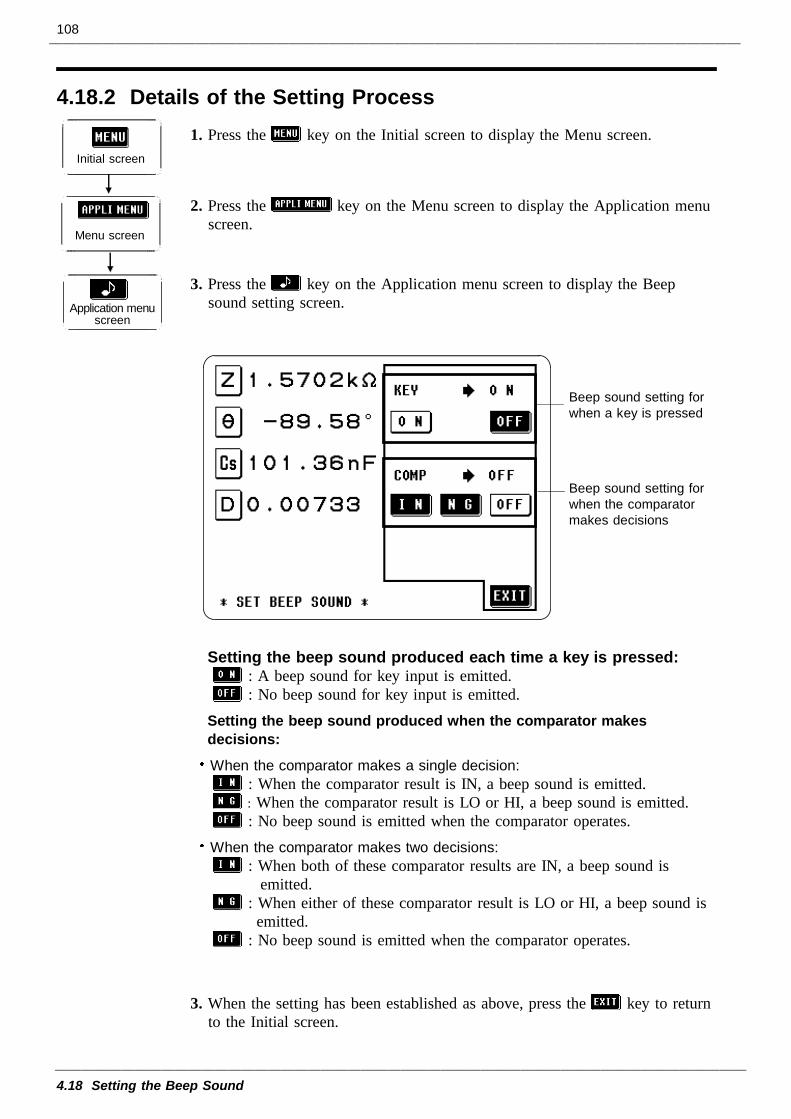
108
4.18 Setting the Beep Sound
4.18.2 Details of the Setting Process
Application menuscreen
Initial screen
Menu screen
Beep sound setting forwhen a key is pressed
Beep sound setting forwhen the comparatormakes decisions
1. Press the key on the Initial screen to display the Menu screen.
2. Press the key on the Menu screen to display the Application menuscreen.
3. Press the key on the Application menu screen to display the Beepsound setting screen.
Setting the beep sound produced each time a key is pressed:: A beep sound for key input is emitted.: No beep sound for key input is emitted.
Setting the beep sound produced when the comparator makesdecisions:
When the comparator makes a single decision:: When the comparator result is IN, a beep sound is emitted.: When the comparator result is LO or HI, a beep sound is emitted.: No beep sound is emitted when the comparator operates.
When the comparator makes two decisions:: When both of these comparator results are IN, a beep sound is
emitted.: When either of these comparator result is LO or HI, a beep sound is
emitted.: No beep sound is emitted when the comparator operates.
3. When the setting has been established as above, press the key to returnto the Initial screen.
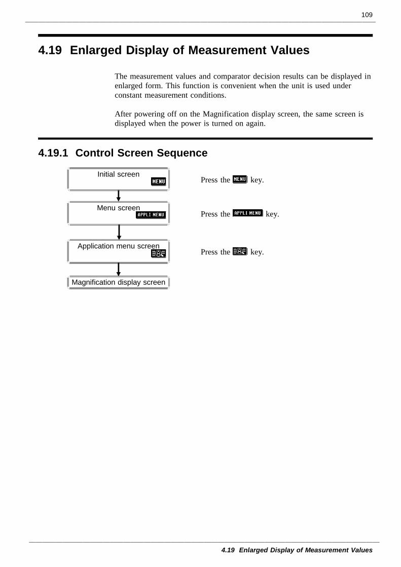
109
4.19 Enlarged Display of Measurement Values
4.19.1 Control Screen Sequence
Initial screen
Menu screen
Application menu screen
Magnification display screen
4.19 Enlarged Display of Measurement Values
The measurement values and comparator decision results can be displayed inenlarged form. This function is convenient when the unit is used underconstant measurement conditions.
After powering off on the Magnification display screen, the same screen isdisplayed when the power is turned on again.
Press the key.
Press the key.
Press the key.
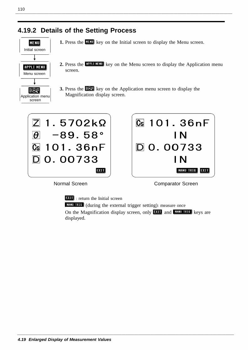
110
4.19 Enlarged Display of Measurement Values
4.19.2 Details of the Setting Process
Initial screen
Application menuscreen
Menu screen
Normal Screen Comparator Screen
1. Press the key on the Initial screen to display the Menu screen.
2. Press the key on the Menu screen to display the Application menuscreen.
3. Press the key on the Application menu screen to display theMagnification display screen.
: return the Initial screen(during the external trigger setting): measure once
On the Magnification display screen, only and keys aredisplayed.
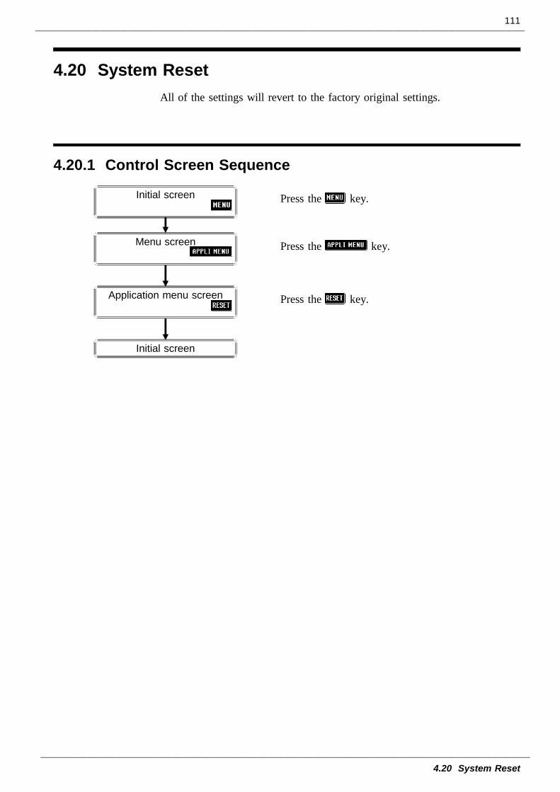
111
4.20 System Reset
4.20.1 Control Screen Sequence
Initial screen
Menu screen
Application menu screen
Initial screen
4.20 System ResetAll of the settings will revert to the factory original settings.
Press the key.
Press the key.
Press the key.
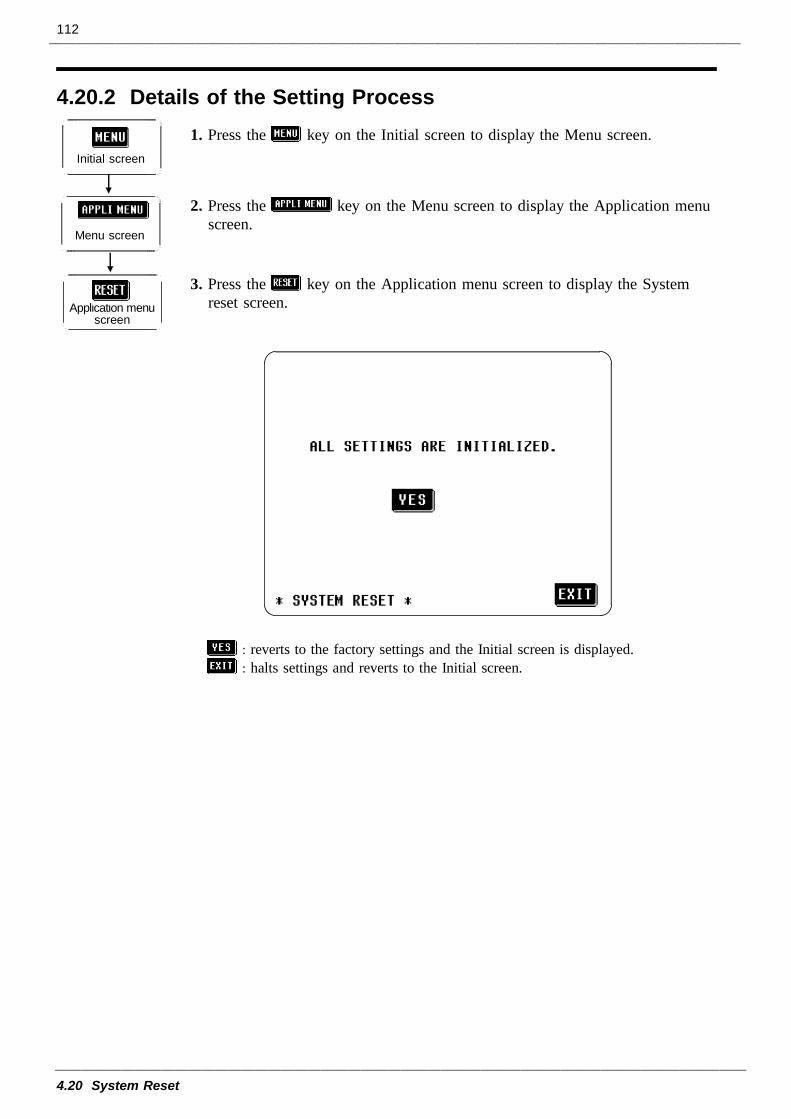
112
4.20 System Reset
4.20.2 Details of the Setting Process
Initial screen
Menu screen
Application menuscreen
1. Press the key on the Initial screen to display the Menu screen.
2. Press the key on the Menu screen to display the Application menuscreen.
3. Press the key on the Application menu screen to display the Systemreset screen.
: reverts to the factory settings and the Initial screen is displayed.: halts settings and reverts to the Initial screen.
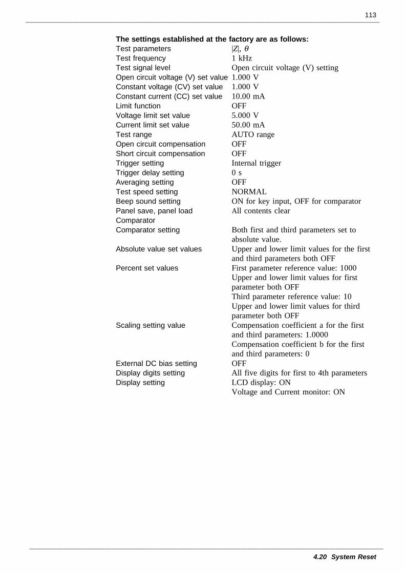
113
4.20 System Reset
The settings established at the factory are as follows:Test parameters |Z|, θTest frequency 1 kHzTest signal level Open circuit voltage (V) settingOpen circuit voltage (V) set value 1.000 VConstant voltage (CV) set value 1.000 VConstant current (CC) set value 10.00 mALimit function OFFVoltage limit set value 5.000 VCurrent limit set value 50.00 mATest range AUTO rangeOpen circuit compensation OFFShort circuit compensation OFFTrigger setting Internal triggerTrigger delay setting 0 sAveraging setting OFFTest speed setting NORMALBeep sound setting ON for key input, OFF for comparatorPanel save, panel load All contents clearComparatorComparator setting Both first and third parameters set to
absolute value.Absolute value set values Upper and lower limit values for the first
and third parameters both OFFPercent set values First parameter reference value: 1000 Upper and lower limit values for first
parameter both OFF Third parameter reference value: 10 Upper and lower limit values for third
parameter both OFFScaling setting value Compensation coefficient a for the first
and third parameters: 1.0000Compensation coefficient b for the firstand third parameters: 0
External DC bias setting OFFDisplay digits setting All five digits for first to 4th parametersDisplay setting LCD display: ON
Voltage and Current monitor: ON
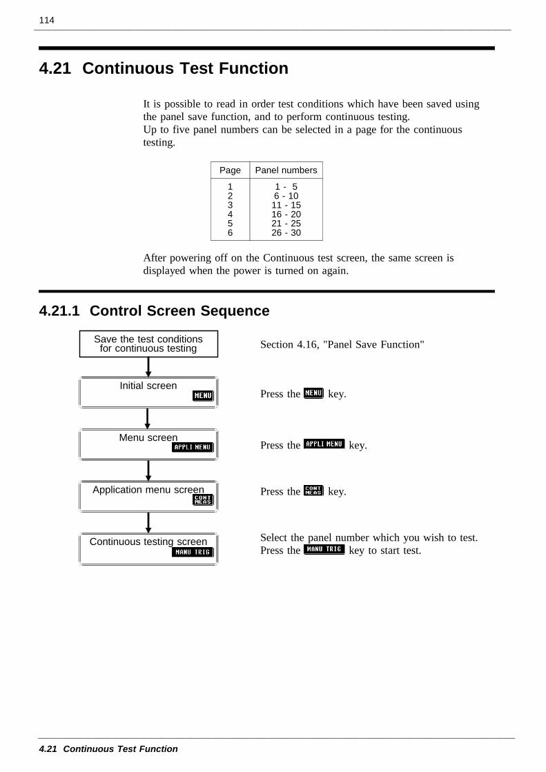
114
4.21 Continuous Test Function
Page Panel numbers
123456
1 - 56 - 1011 - 1516 - 2021 - 2526 - 30
4.21.1 Control Screen Sequence
Initial screen
Menu screen
Application menu screen
Save the test conditionsfor continuous testing
Continuous testing screen
4.21 Continuous Test Function
It is possible to read in order test conditions which have been saved usingthe panel save function, and to perform continuous testing.Up to five panel numbers can be selected in a page for the continuoustesting.
After powering off on the Continuous test screen, the same screen isdisplayed when the power is turned on again.
Section 4.16, "Panel Save Function"
Press the key.
Press the key.
Press the key.
Select the panel number which you wish to test.Press the key to start test.
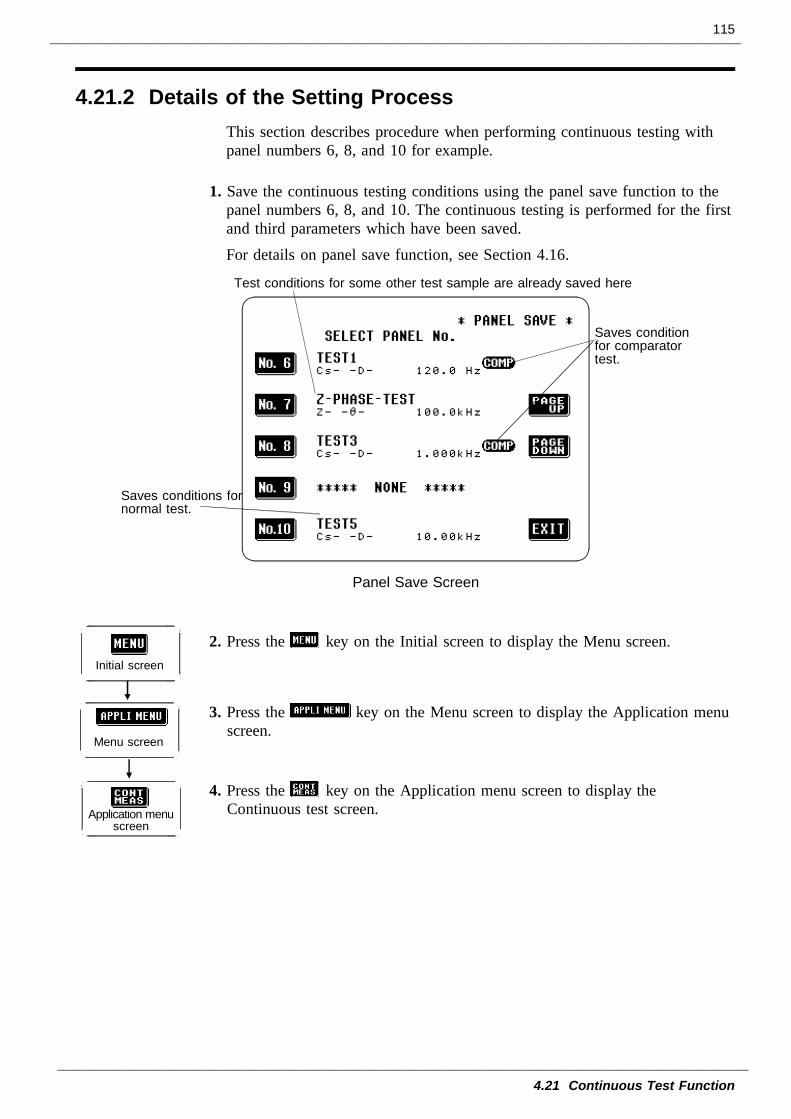
115
4.21 Continuous Test Function
4.21.2 Details of the Setting Process
Saves conditions fornormal test.
Test conditions for some other test sample are already saved here
Saves conditionfor comparatortest.
Panel Save Screen
Initial screen
Menu screen
Application menuscreen
This section describes procedure when performing continuous testing withpanel numbers 6, 8, and 10 for example.
1. Save the continuous testing conditions using the panel save function to thepanel numbers 6, 8, and 10. The continuous testing is performed for the firstand third parameters which have been saved.For details on panel save function, see Section 4.16.
2. Press the key on the Initial screen to display the Menu screen.
3. Press the key on the Menu screen to display the Application menuscreen.
4. Press the key on the Application menu screen to display theContinuous test screen.
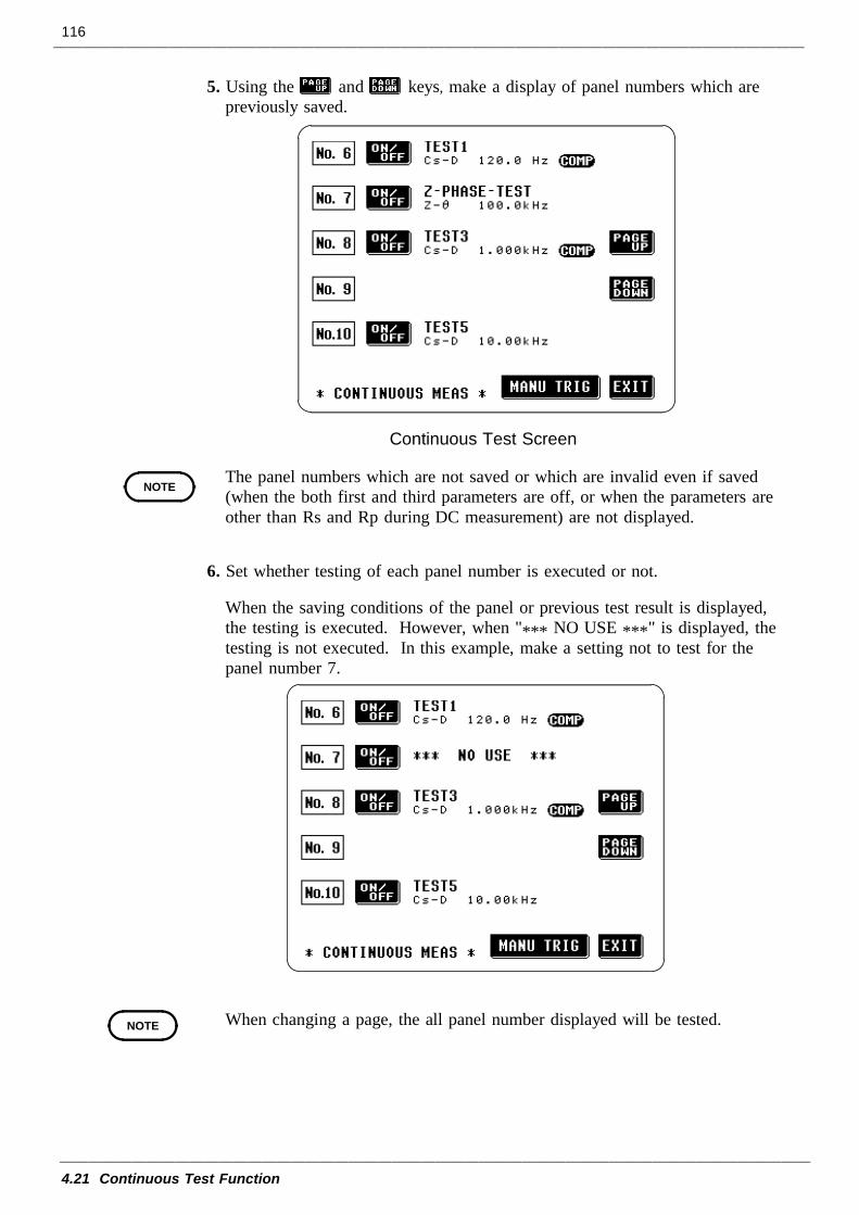
116
4.21 Continuous Test Function
Continuous Test Screen
NOTE
NOTE
5. Using the and keys, make a display of panel numbers which arepreviously saved.
The panel numbers which are not saved or which are invalid even if saved(when the both first and third parameters are off, or when the parameters areother than Rs and Rp during DC measurement) are not displayed.
6. Set whether testing of each panel number is executed or not.
When the saving conditions of the panel or previous test result is displayed,the testing is executed. However, when "*** NO USE ***" is displayed, thetesting is not executed. In this example, make a setting not to test for thepanel number 7.
When changing a page, the all panel number displayed will be tested.
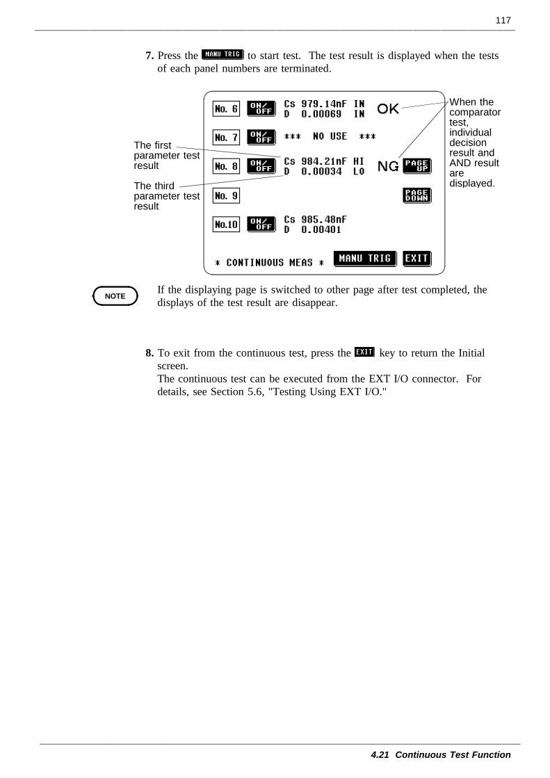
117
4.21 Continuous Test Function
The firstparameter testresult
The thirdparameter testresult
When thecomparatortest,individualdecisionresult andAND resultaredisplayed.
NOTE
7. Press the to start test. The test result is displayed when the testsof each panel numbers are terminated.
If the displaying page is switched to other page after test completed, thedisplays of the test result are disappear.
8. To exit from the continuous test, press the key to return the Initialscreen.The continuous test can be executed from the EXT I/O connector. Fordetails, see Section 5.6, "Testing Using EXT I/O."
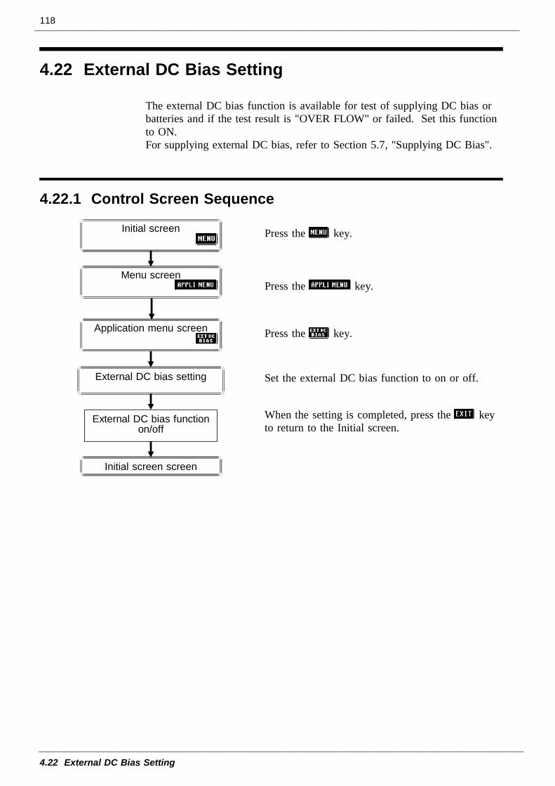
118
4.22 External DC Bias Setting
4.22.1 Control Screen Sequence
External DC bias functionon/off
Initial screen screen
External DC bias setting
Initial screen
Menu screen
Application menu screen
4.22 External DC Bias Setting
The external DC bias function is available for test of supplying DC bias orbatteries and if the test result is "OVER FLOW" or failed. Set this functionto ON.For supplying external DC bias, refer to Section 5.7, "Supplying DC Bias".
Press the key.
Press the key.
Press the key.
Set the external DC bias function to on or off.
When the setting is completed, press the keyto return to the Initial screen.
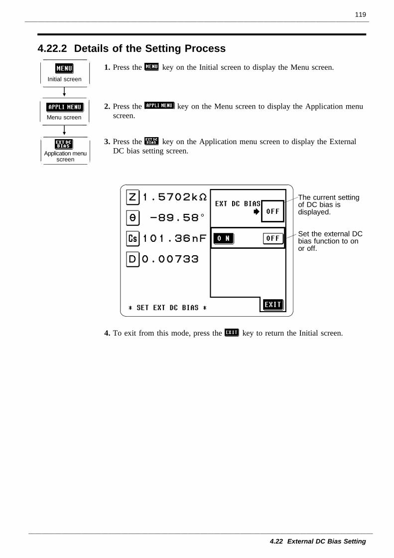
119
4.22 External DC Bias Setting
4.22.2 Details of the Setting Process
Initial screen
Application menuscreen
Menu screen
The current settingof DC bias isdisplayed.
Set the external DCbias function to onor off.
1. Press the key on the Initial screen to display the Menu screen.
2. Press the key on the Menu screen to display the Application menuscreen.
3. Press the key on the Application menu screen to display the ExternalDC bias setting screen.
4. To exit from this mode, press the key to return the Initial screen.
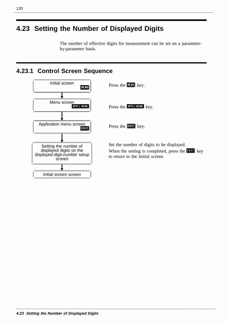
120
4.23 Setting the Number of Displayed Digits
4.23.1 Control Screen Sequence
Initial screen screen
Initial screen
Menu screen
Application menu screen
Setting the number ofdisplayed digits on the
displayed-digit-number setupscreen
4.23 Setting the Number of Displayed Digits
The number of effective digits for measurement can be set on a parameter-by-parameter basis.
Press the key.
Press the key.
Press the key.
Set the number of digits to be displayed.When the setting is completed, press the keyto return to the Initial screen.
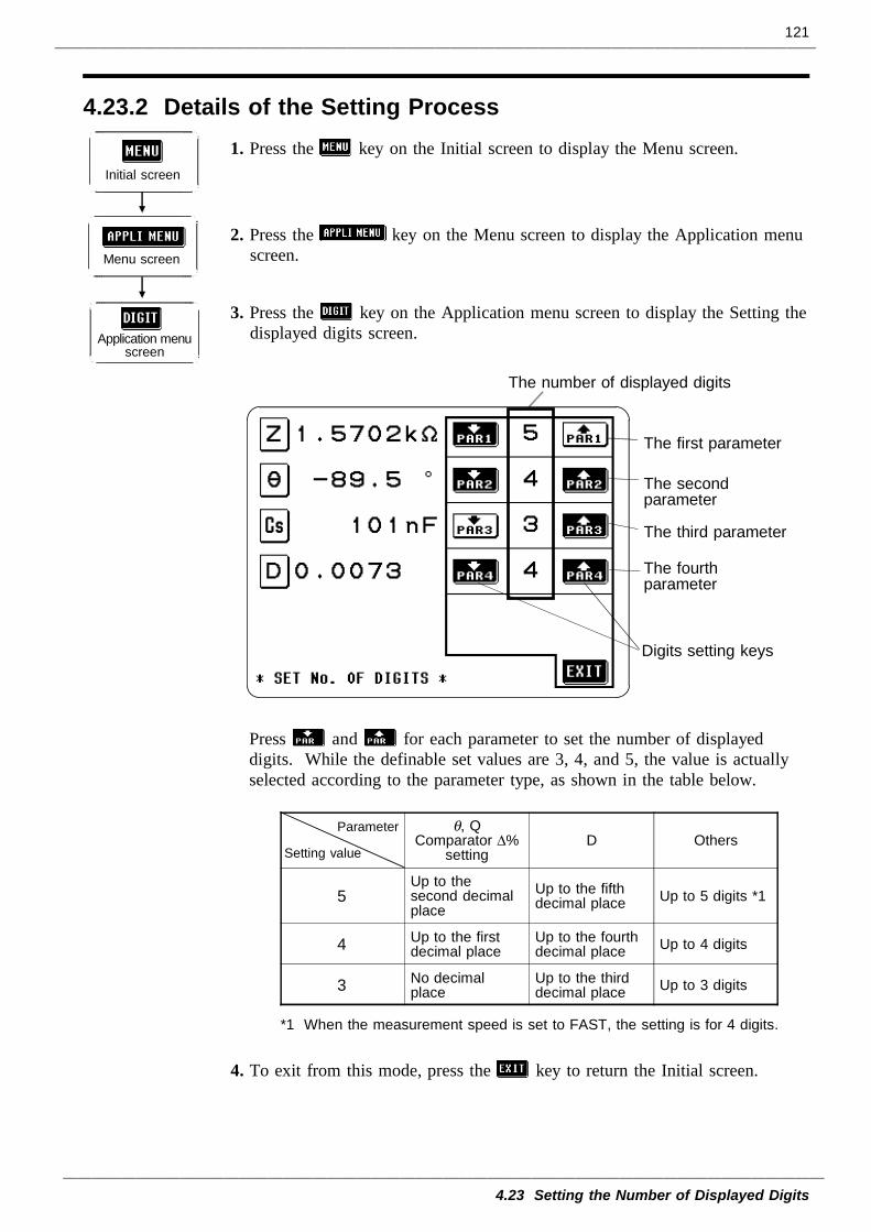
121
4.23 Setting the Number of Displayed Digits
4.23.2 Details of the Setting Process
Initial screen
Application menuscreen
Menu screen
The number of displayed digits
Digits setting keys
The first parameter
The secondparameter
The third parameter
The fourthparameter
Parameter
Setting value
θ, QComparator ∆%
settingD Others
5Up to thesecond decimalplace
Up to the fifthdecimal place Up to 5 digits *1
4 Up to the firstdecimal place
Up to the fourthdecimal place Up to 4 digits
3 No decimalplace
Up to the thirddecimal place Up to 3 digits
*1 When the measurement speed is set to FAST, the setting is for 4 digits.
1. Press the key on the Initial screen to display the Menu screen.
2. Press the key on the Menu screen to display the Application menuscreen.
3. Press the key on the Application menu screen to display the Setting thedisplayed digits screen.
Press and for each parameter to set the number of displayeddigits. While the definable set values are 3, 4, and 5, the value is actuallyselected according to the parameter type, as shown in the table below.
4. To exit from this mode, press the key to return the Initial screen.
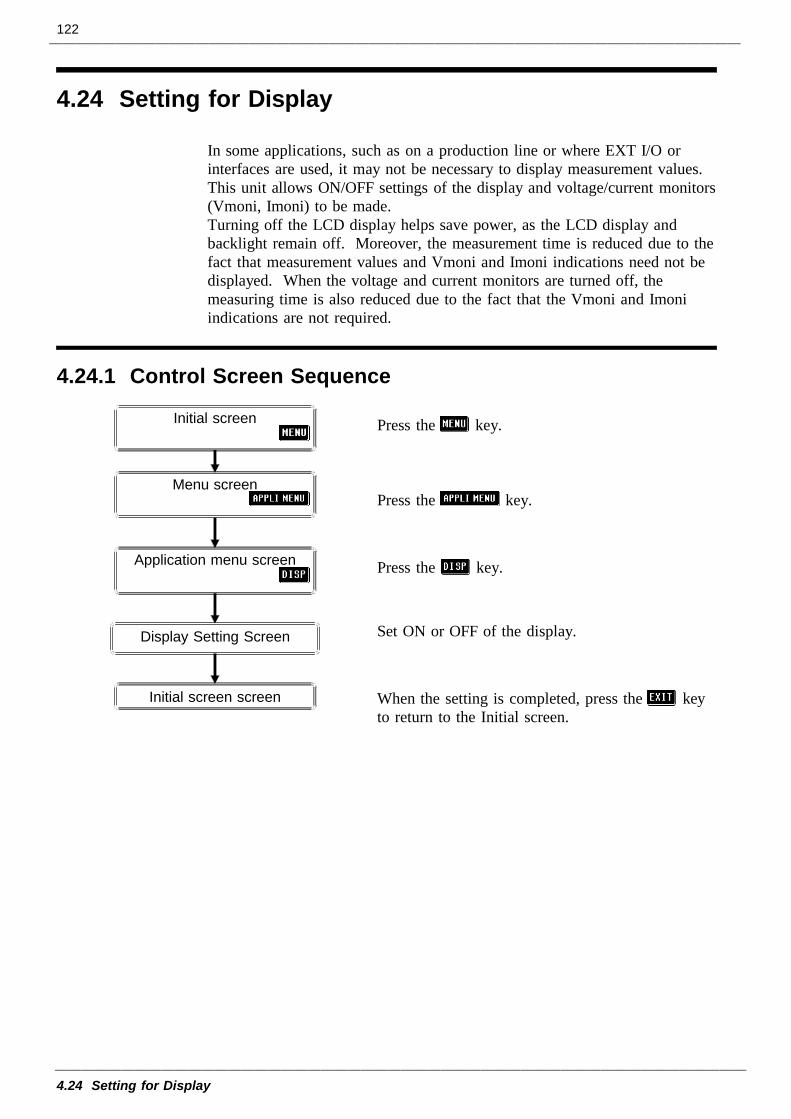
122
4.24 Setting for Display
4.24.1 Control Screen Sequence
Initial screen screen
Initial screen
Menu screen
Application menu screen
Display Setting Screen
4.24 Setting for Display
In some applications, such as on a production line or where EXT I/O orinterfaces are used, it may not be necessary to display measurement values.This unit allows ON/OFF settings of the display and voltage/current monitors(Vmoni, Imoni) to be made.Turning off the LCD display helps save power, as the LCD display andbacklight remain off. Moreover, the measurement time is reduced due to thefact that measurement values and Vmoni and Imoni indications need not bedisplayed. When the voltage and current monitors are turned off, themeasuring time is also reduced due to the fact that the Vmoni and Imoniindications are not required.
Press the key.
Press the key.
Press the key.
Set ON or OFF of the display.
When the setting is completed, press the keyto return to the Initial screen.
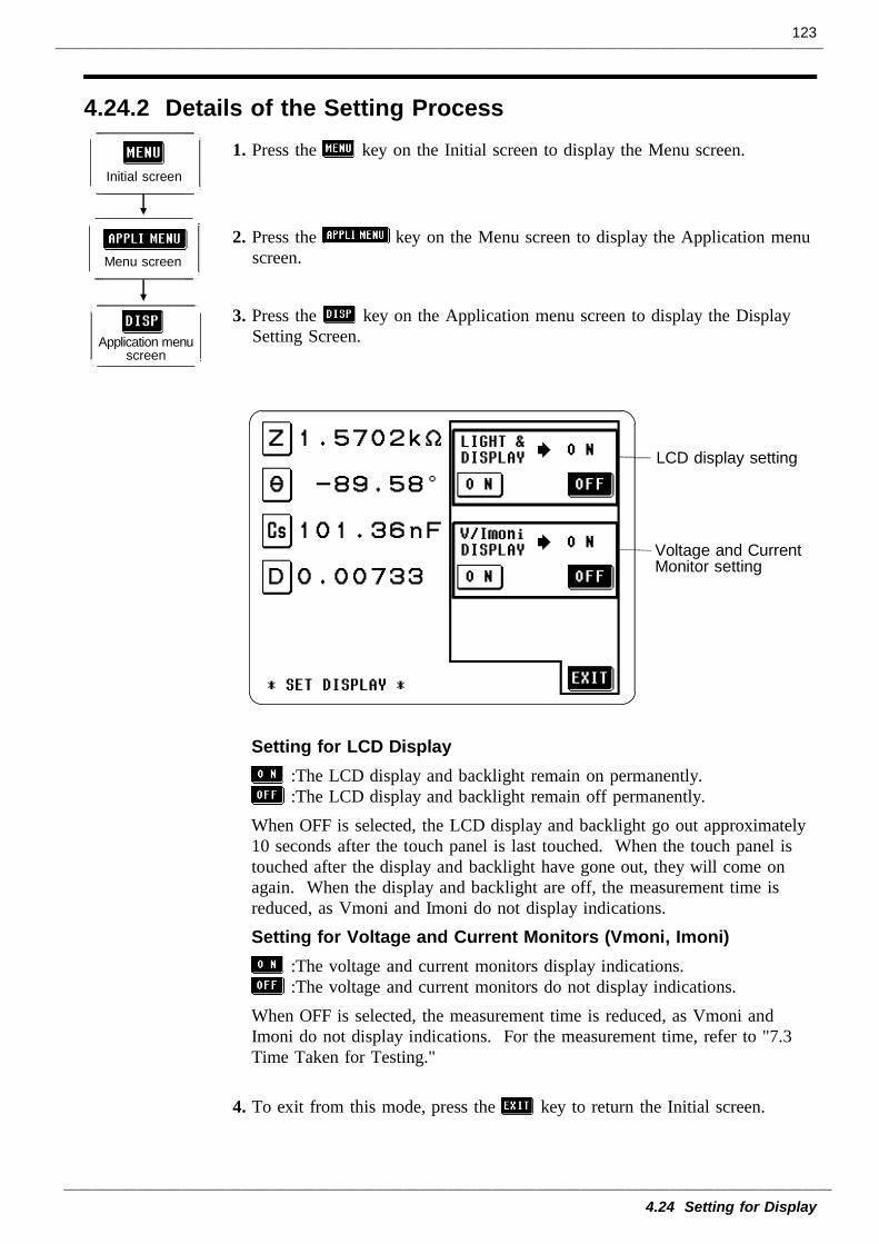
123
4.24 Setting for Display
4.24.2 Details of the Setting Process
Initial screen
Application menuscreen
Menu screen
LCD display setting
Voltage and CurrentMonitor setting
1. Press the key on the Initial screen to display the Menu screen.
2. Press the key on the Menu screen to display the Application menuscreen.
3. Press the key on the Application menu screen to display the DisplaySetting Screen.
Setting for LCD Display:The LCD display and backlight remain on permanently.:The LCD display and backlight remain off permanently.
When OFF is selected, the LCD display and backlight go out approximately10 seconds after the touch panel is last touched. When the touch panel istouched after the display and backlight have gone out, they will come onagain. When the display and backlight are off, the measurement time isreduced, as Vmoni and Imoni do not display indications.Setting for Voltage and Current Monitors (Vmoni, Imoni)
:The voltage and current monitors display indications.:The voltage and current monitors do not display indications.
When OFF is selected, the measurement time is reduced, as Vmoni andImoni do not display indications. For the measurement time, refer to "7.3Time Taken for Testing."
4. To exit from this mode, press the key to return the Initial screen.
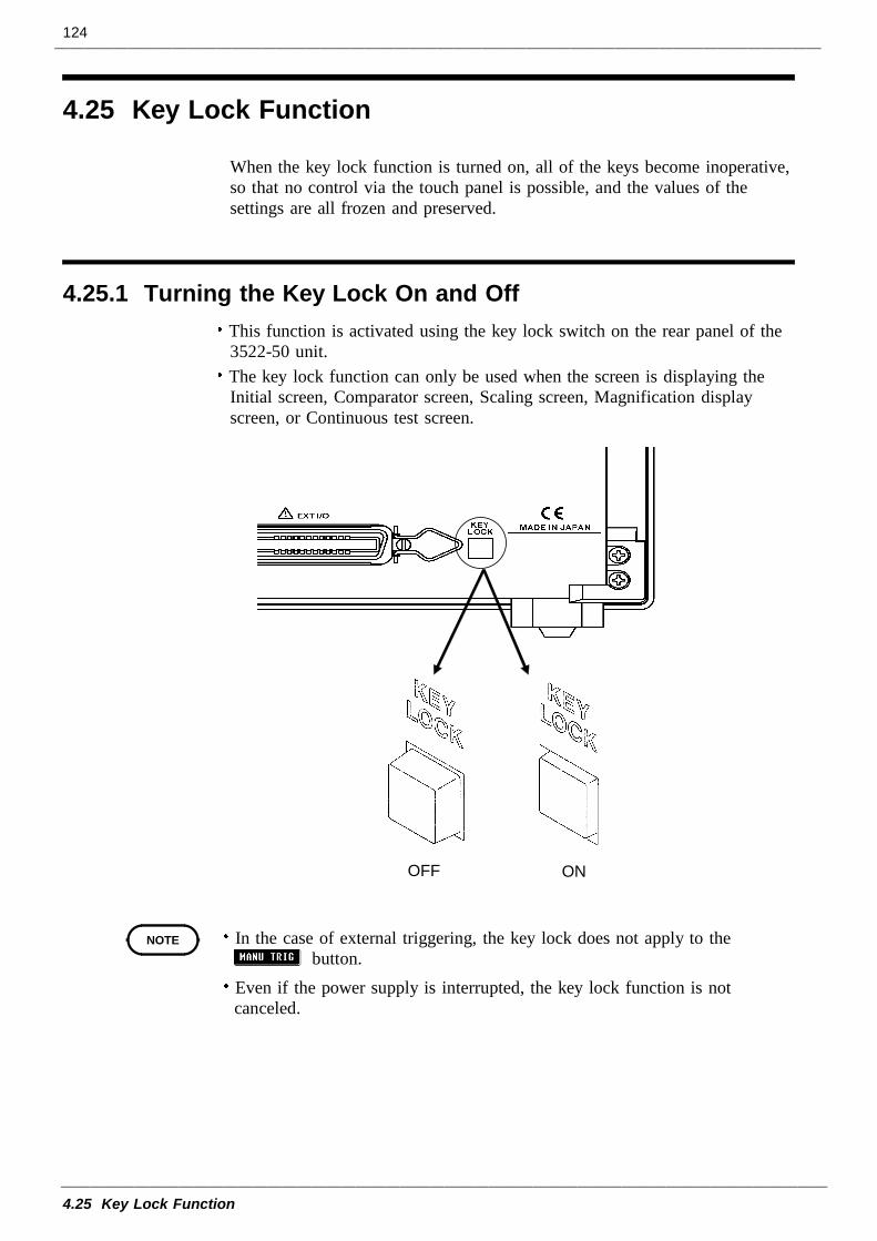
124
4.25 Key Lock Function
4.25.1 Turning the Key Lock On and Off
OFF ON
NOTE
4.25 Key Lock Function
When the key lock function is turned on, all of the keys become inoperative,so that no control via the touch panel is possible, and the values of thesettings are all frozen and preserved.
This function is activated using the key lock switch on the rear panel of the3522-50 unit.The key lock function can only be used when the screen is displaying theInitial screen, Comparator screen, Scaling screen, Magnification displayscreen, or Continuous test screen.
In the case of external triggering, the key lock does not apply to thebutton.
Even if the power supply is interrupted, the key lock function is notcanceled.
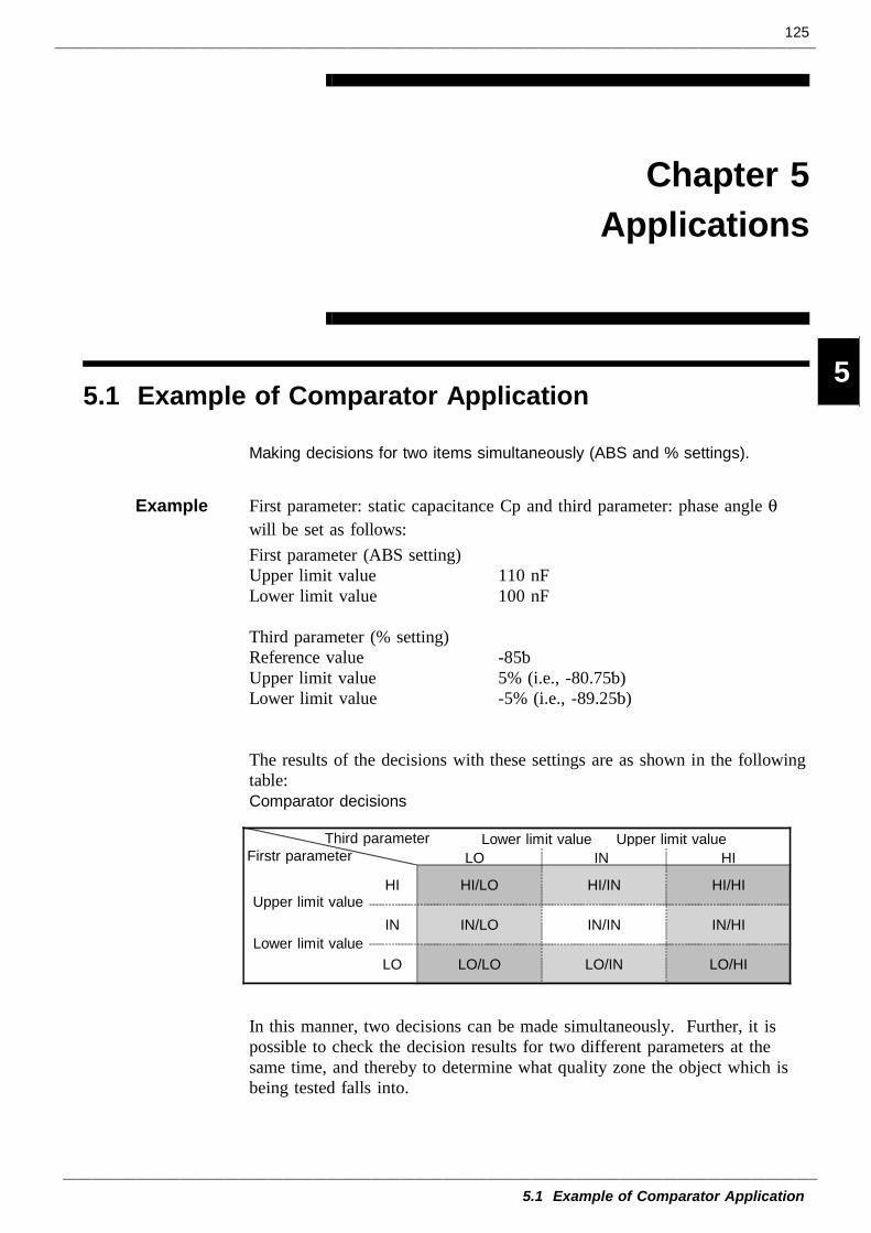
125
5.1 Example of Comparator Application
1
2
3
4
5
6
7
8
9
10
11
12
13
14
A
Firstr parameterLower limit value Upper limit value
LO IN HI
Upper limit value
Lower limit value
HI HI/LO HI/IN HI/HI
IN IN/LO IN/IN IN/HI
LO LO/LO LO/IN LO/HI
Third parameter
Chapter 5Applications
5.1 Example of Comparator Application
Making decisions for two items simultaneously (ABS and % settings).
Example First parameter: static capacitance Cp and third parameter: phase angle θwill be set as follows:First parameter (ABS setting)Upper limit value 110 nFLower limit value 100 nF
Third parameter (% setting)Reference value -85゚Upper limit value 5% (i.e., -80.75゚)Lower limit value -5% (i.e., -89.25゚)
The results of the decisions with these settings are as shown in the followingtable:Comparator decisions
In this manner, two decisions can be made simultaneously. Further, it ispossible to check the decision results for two different parameters at thesame time, and thereby to determine what quality zone the object which isbeing tested falls into.
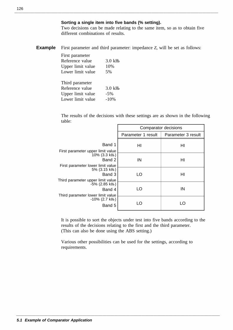
126
5.1 Example of Comparator Application
Comparator decisionsParameter 1 result Parameter 3 result
Band 1First parameter upper limit value
10% (3.3 kΩ)Band 2
First parameter lower limit value5% (3.15 kΩ)
Band 3Third parameter upper limit value
-5% (2.85 kΩ)Band 4
Third parameter lower limit value-10% (2.7 kΩ)
Band 5
HI HI
IN HI
LO HI
LO IN
LO LO
Sorting a single item into five bands (% setting).Two decisions can be made relating to the same item, so as to obtain fivedifferent combinations of results.
Example First parameter and third parameter: impedance Z, will be set as follows:First parameterReference value 3.0 kΩUpper limit value 10%Lower limit value 5%
Third parameterReference value 3.0 kΩUpper limit value -5%Lower limit value -10%
The results of the decisions with these settings are as shown in the followingtable:
It is possible to sort the objects under test into five bands according to theresults of the decisions relating to the first and the third parameter.(This can also be done using the ABS setting.)
Various other possibilities can be used for the settings, according torequirements.
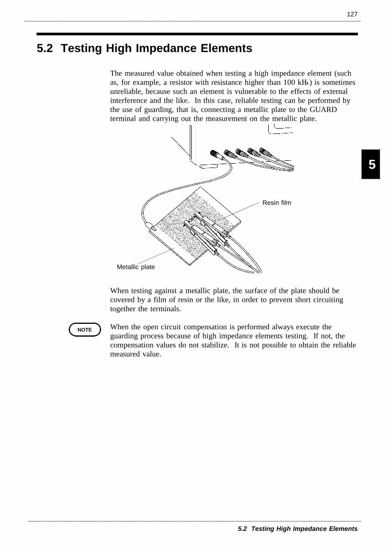
127
5.2 Testing High Impedance Elements
1
2
3
4
5
6
7
8
9
10
11
12
13
14
A
Resin film
Metallic plate
NOTE
5.2 Testing High Impedance Elements
The measured value obtained when testing a high impedance element (suchas, for example, a resistor with resistance higher than 100 kΩ) is sometimesunreliable, because such an element is vulnerable to the effects of externalinterference and the like. In this case, reliable testing can be performed bythe use of guarding, that is, connecting a metallic plate to the GUARDterminal and carrying out the measurement on the metallic plate.
When testing against a metallic plate, the surface of the plate should becovered by a film of resin or the like, in order to prevent short circuitingtogether the terminals.
When the open circuit compensation is performed always execute theguarding process because of high impedance elements testing. If not, thecompensation values do not stabilize. It is not possible to obtain the reliablemeasured value.
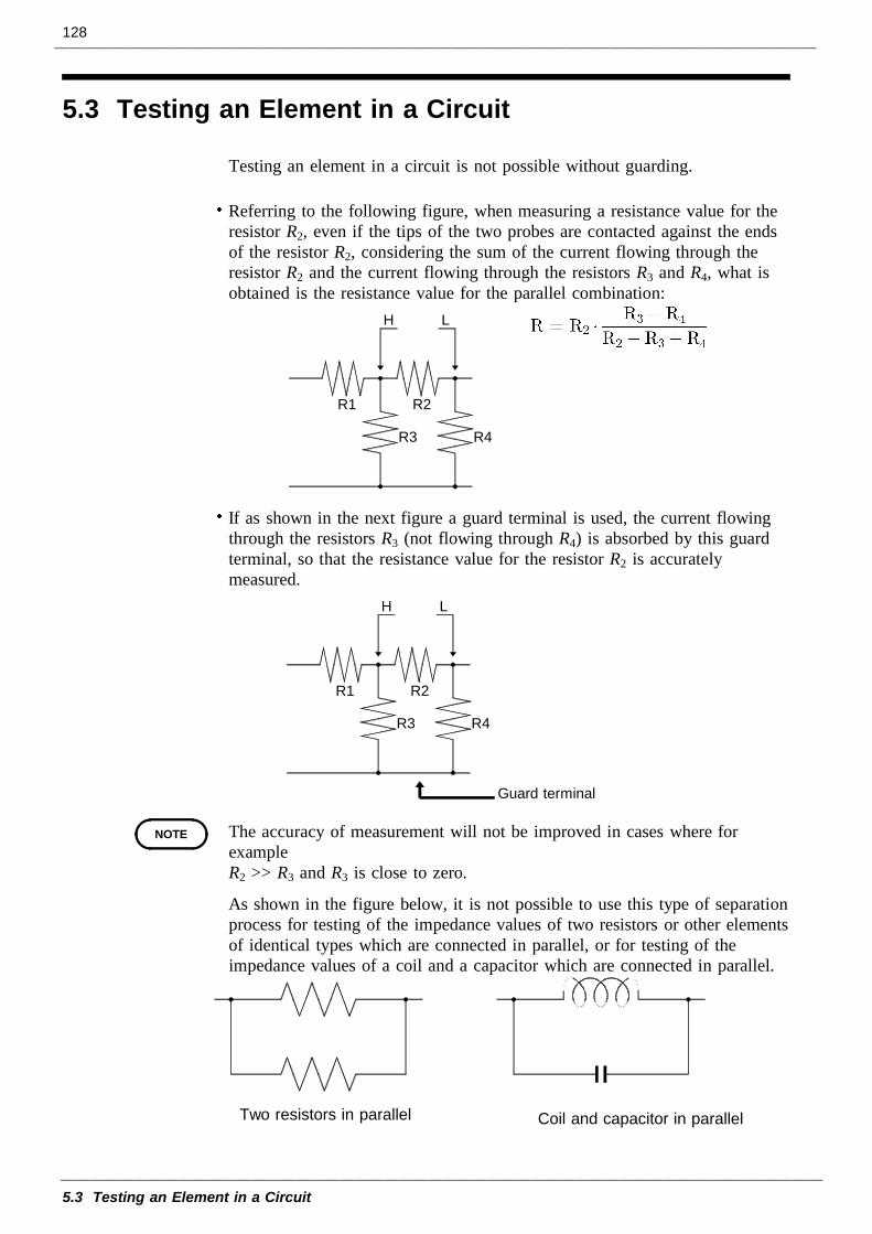
128
5.3 Testing an Element in a Circuit
R4R3
R2R1
H L
R4R3
R2R1
H L
Guard terminal
NOTE
Two resistors in parallel Coil and capacitor in parallel
5.3 Testing an Element in a Circuit
Testing an element in a circuit is not possible without guarding.
Referring to the following figure, when measuring a resistance value for theresistor R2, even if the tips of the two probes are contacted against the endsof the resistor R2, considering the sum of the current flowing through theresistor R2 and the current flowing through the resistors R3 and R4, what isobtained is the resistance value for the parallel combination:
If as shown in the next figure a guard terminal is used, the current flowingthrough the resistors R3 (not flowing through R4) is absorbed by this guardterminal, so that the resistance value for the resistor R2 is accuratelymeasured.
The accuracy of measurement will not be improved in cases where forexampleR2 >> R3 and R3 is close to zero.
As shown in the figure below, it is not possible to use this type of separationprocess for testing of the impedance values of two resistors or other elementsof identical types which are connected in parallel, or for testing of theimpedance values of a coil and a capacitor which are connected in parallel.
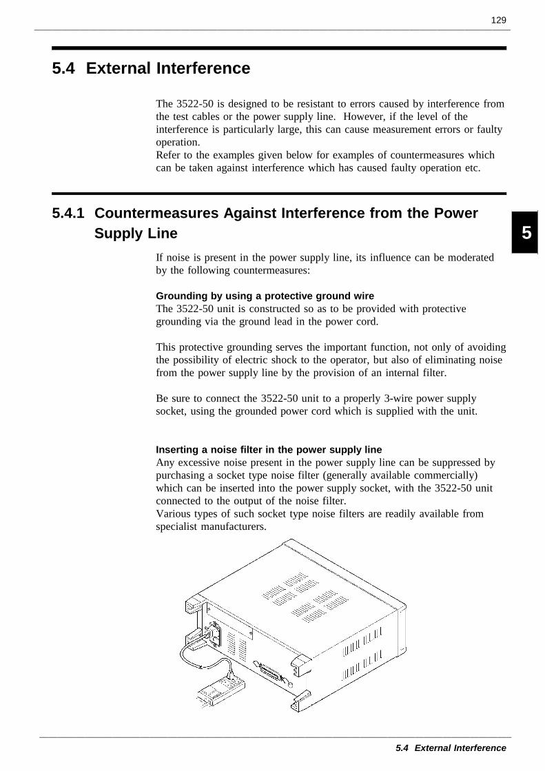
129
5.4 External Interference
1
2
3
4
5
6
7
8
9
10
11
12
13
14
A
5.4.1 Countermeasures Against Interference from the PowerSupply Line
5.4 External Interference
The 3522-50 is designed to be resistant to errors caused by interference fromthe test cables or the power supply line. However, if the level of theinterference is particularly large, this can cause measurement errors or faultyoperation.Refer to the examples given below for examples of countermeasures whichcan be taken against interference which has caused faulty operation etc.
If noise is present in the power supply line, its influence can be moderatedby the following countermeasures:
Grounding by using a protective ground wireThe 3522-50 unit is constructed so as to be provided with protectivegrounding via the ground lead in the power cord.
This protective grounding serves the important function, not only of avoidingthe possibility of electric shock to the operator, but also of eliminating noisefrom the power supply line by the provision of an internal filter.
Be sure to connect the 3522-50 unit to a properly 3-wire power supplysocket, using the grounded power cord which is supplied with the unit.
Inserting a noise filter in the power supply lineAny excessive noise present in the power supply line can be suppressed bypurchasing a socket type noise filter (generally available commercially)which can be inserted into the power supply socket, with the 3522-50 unitconnected to the output of the noise filter.Various types of such socket type noise filters are readily available fromspecialist manufacturers.
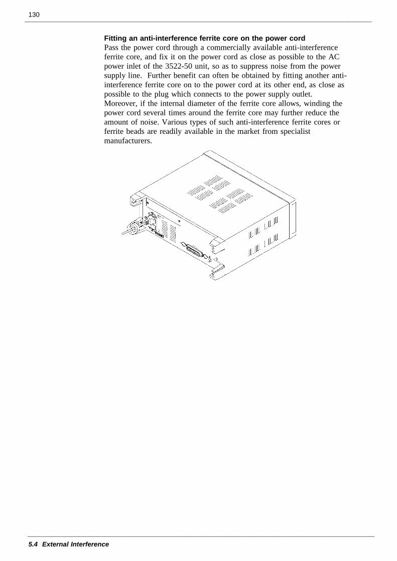
130
5.4 External Interference
Fitting an anti-interference ferrite core on the power cordPass the power cord through a commercially available anti-interferenceferrite core, and fix it on the power cord as close as possible to the ACpower inlet of the 3522-50 unit, so as to suppress noise from the powersupply line. Further benefit can often be obtained by fitting another anti-interference ferrite core on to the power cord at its other end, as close aspossible to the plug which connects to the power supply outlet.Moreover, if the internal diameter of the ferrite core allows, winding thepower cord several times around the ferrite core may further reduce theamount of noise. Various types of such anti-interference ferrite cores orferrite beads are readily available in the market from specialistmanufacturers.
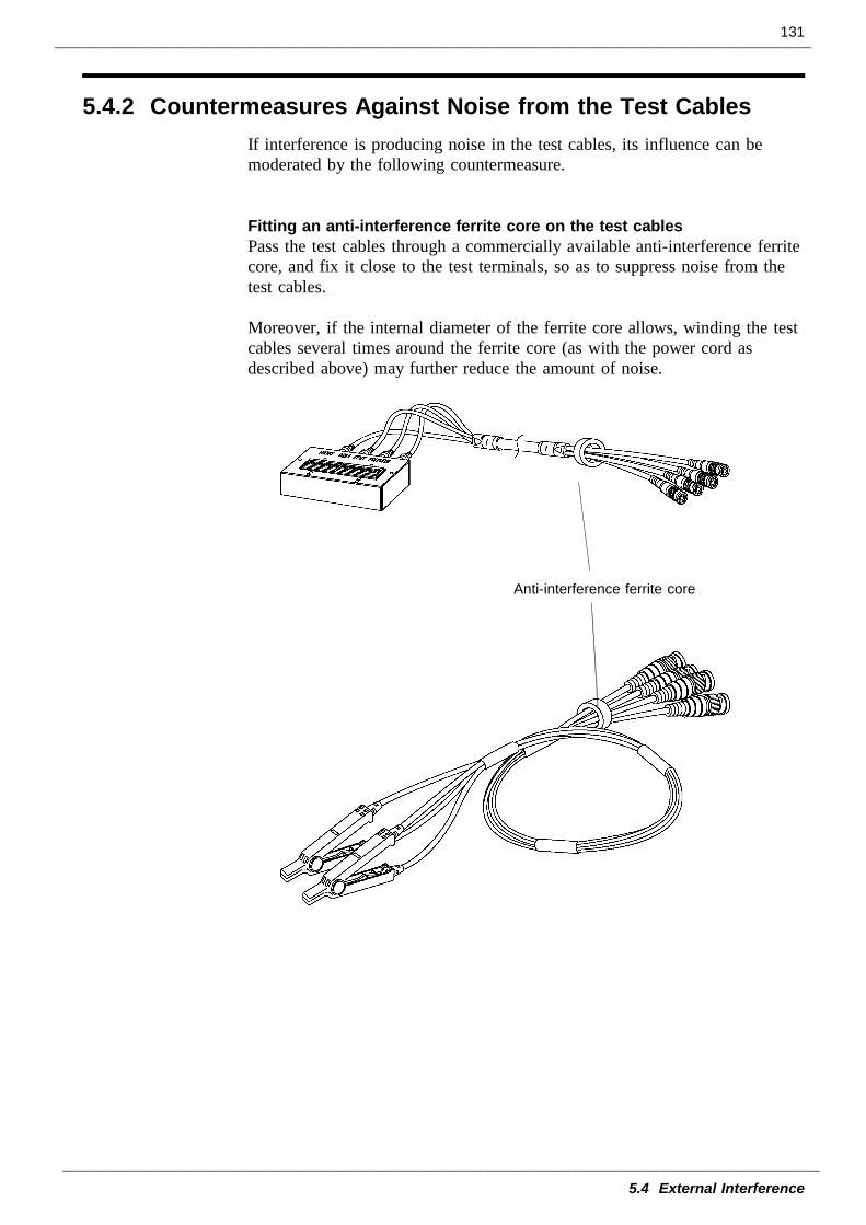
131
5.4 External Interference
5.4.2 Countermeasures Against Noise from the Test Cables
Anti-interference ferrite core
If interference is producing noise in the test cables, its influence can bemoderated by the following countermeasure.
Fitting an anti-interference ferrite core on the test cablesPass the test cables through a commercially available anti-interference ferritecore, and fix it close to the test terminals, so as to suppress noise from thetest cables.
Moreover, if the internal diameter of the ferrite core allows, winding the testcables several times around the ferrite core (as with the power cord asdescribed above) may further reduce the amount of noise.
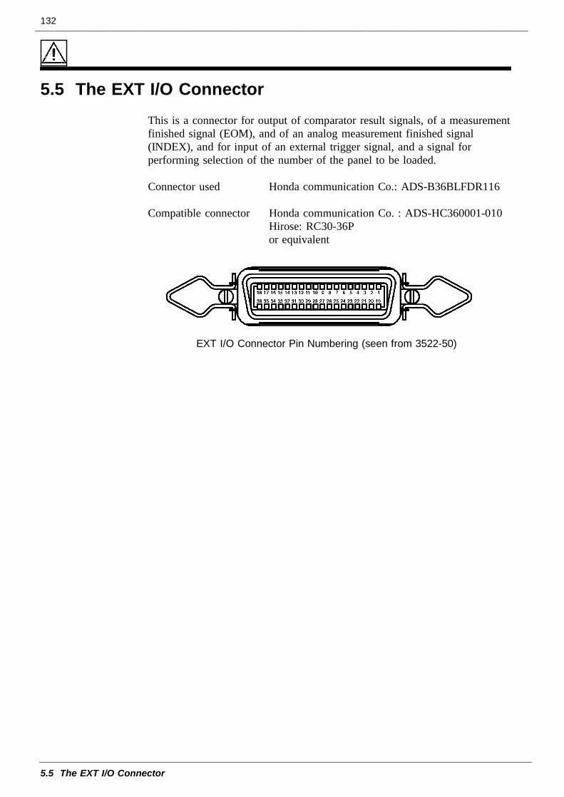
132
5.5 The EXT I/O Connector
EXT I/O Connector Pin Numbering (seen from 3522-50)
5.5 The EXT I/O ConnectorThis is a connector for output of comparator result signals, of a measurementfinished signal (EOM), and of an analog measurement finished signal(INDEX), and for input of an external trigger signal, and a signal forperforming selection of the number of the panel to be loaded.
Connector used Honda communication Co.: ADS-B36BLFDR116
Compatible connector Honda communication Co. : ADS-HC360001-010 Hirose: RC30-36P or equivalent
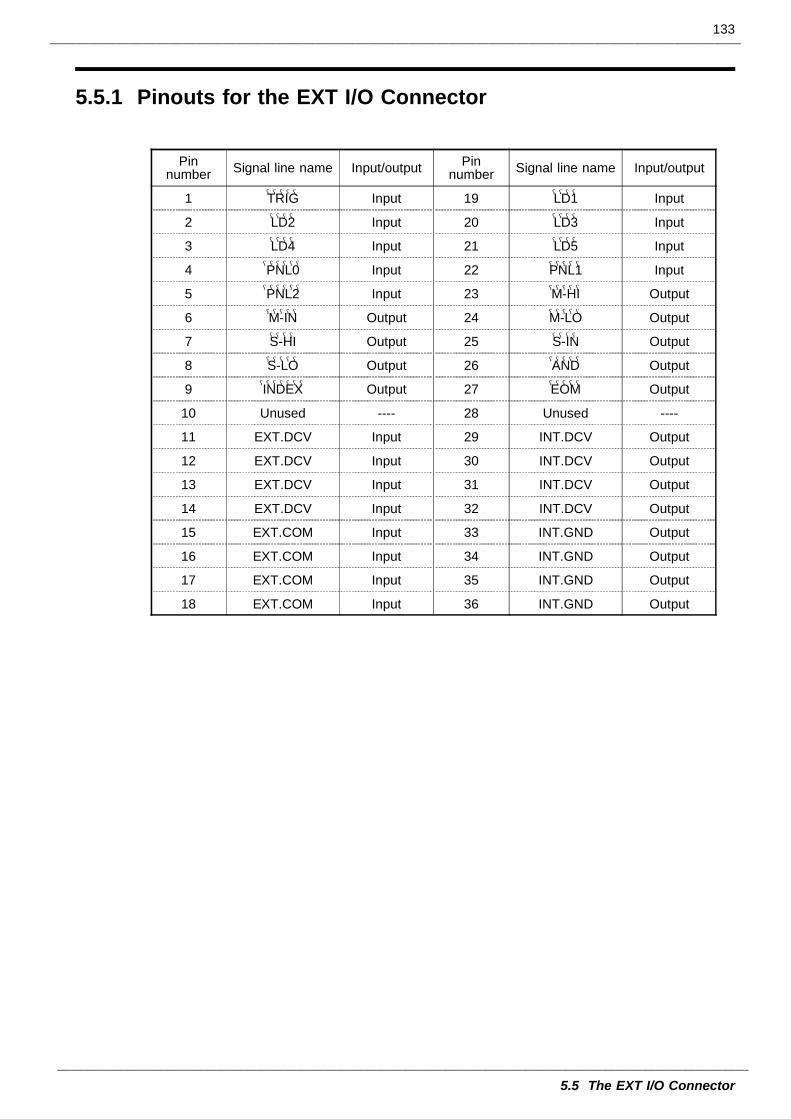
133
5.5 The EXT I/O Connector
5.5.1 Pinouts for the EXT I/O Connector
Pinnumber Signal line name Input/output
1 TRIG――――― Input
2 LD2―――― Input
3 LD4―――― Input
4 PNL0―――――― Input
5 PNL2―――――― Input
6 M-IN――――― Output
7 S-HI―――― Output
8 S-LO――――― Output
9 INDEX――――――― Output
10 Unused ----
11 EXT.DCV Input
12 EXT.DCV Input
13 EXT.DCV Input
14 EXT.DCV Input
15 EXT.COM Input
16 EXT.COM Input
17 EXT.COM Input
18 EXT.COM Input
Pinnumber Signal line name Input/output
19 LD1―――― Input
20 LD3―――― Input
21 LD5―――― Input
22 PNL1――――― Input
23 M-HI――――― Output
24 M-LO――――― Output
25 S-IN―――― Output
26 AND――――― Output
27 EOM――――― Output
28 Unused ----
29 INT.DCV Output
30 INT.DCV Output
31 INT.DCV Output
32 INT.DCV Output
33 INT.GND Output
34 INT.GND Output
35 INT.GND Output
36 INT.GND Output
134
5.5 The EXT I/O Connector
5.5.2 Signal Lines for the EXT I/O ConnectorNOTE
NOTE
All input signals are all negative logic.
(1) M-HI________
, M-IN________
, M-LO__________
(Output signal of comparator result)These lines output the comparator result for the first parameter.
(2) S-HI________
, S-IN__________
, S-LO__________
(Output signal of comparator result)These lines output the comparator result for the third parameter.
(3) AND_________
(Output signal of comparator result)This signal is used to comprehensively evaluate the decision results for thefirst and third parameters.This signal is output only if both the first parameter comparator result andthe third parameter comparator result are IN.
(4) EOM__________
(End of measurement signal)This signal is continuously output during measurement. When this signal isHI, the most recent comparator result is used for the evaluation. The nexttrigger signal can also be input.
(5) INDEX______________
(Signal during analog measurement)Output during analog measurement. When this signal is HI, the object undertest can be changed.
INDEX______________
signal is output at each time of retest. Therefore, when the objectunder test is changed, the settings of the test signal level, current and voltagelimits, test range, and average are specified as followings.
Test signal level Open-circuit voltage (V) settingCurrent and voltage limits OFFTest range HOLD rangeAverage OFF
For the settings other than above, change the object under test referring toEOM___________
.
(6) EXT.DCV, EXT.COM
These are terminals for supplying a power supply voltage from an externaldevice. This enables the 3522-50 unit to be connected to an external devicewhile maintaining the isolation. The range of power voltage which can beconnected is from +5 to +24 volts DC.
(7) INT.DCV, INT.GNDThese lines output +5 VDC and COM from the 3522-50 unit.
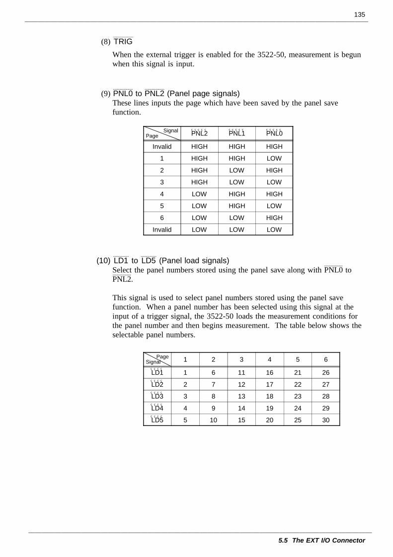
135
5.5 The EXT I/O Connector
SignalPage PNL2――――― PNL1――――― PNL0―――――
Invalid HIGH HIGH HIGH
1 HIGH HIGH LOW
2 HIGH LOW HIGH
3 HIGH LOW LOW
4 LOW HIGH HIGH
5 LOW HIGH LOW
6 LOW LOW HIGH
Invalid LOW LOW LOW
PageSignal 1 2 3 4 5 6
LD1―――― 1 6 11 16 21 26
LD2―――― 2 7 12 17 22 27
LD3―――― 3 8 13 18 23 28
LD4―――― 4 9 14 19 24 29
LD5―――― 5 10 15 20 25 30
(8) TRIG___________
When the external trigger is enabled for the 3522-50, measurement is begunwhen this signal is input.
(9) PNL0---------------
to PNL2---------------
(Panel page signals)These lines inputs the page which have been saved by the panel savefunction.
(10) LD1------------
to LD5------------
(Panel load signals)Select the panel numbers stored using the panel save along with PNL0
--------------to
PNL2--------------
.
This signal is used to select panel numbers stored using the panel savefunction. When a panel number has been selected using this signal at theinput of a trigger signal, the 3522-50 loads the measurement conditions forthe panel number and then begins measurement. The table below shows theselectable panel numbers.
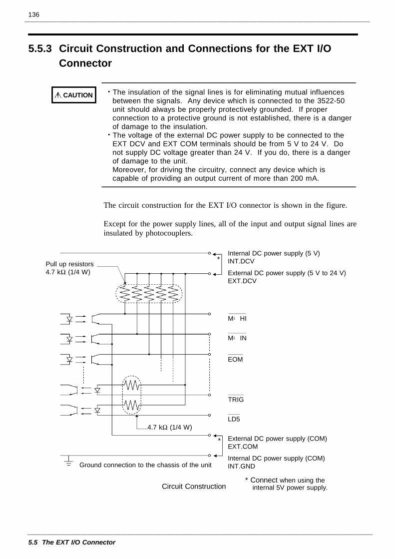
136
5.5 The EXT I/O Connector
5.5.3 Circuit Construction and Connections for the EXT I/OConnector
CAUTION The insulation of the signal lines is for eliminating mutual influencesbetween the signals. Any device which is connected to the 3522-50unit should always be properly protectively grounded. If properconnection to a protective ground is not established, there is a dangerof damage to the insulation.The voltage of the external DC power supply to be connected to theEXT DCV and EXT COM terminals should be from 5 V to 24 V. Donot supply DC voltage greater than 24 V. If you do, there is a dangerof damage to the unit.Moreover, for driving the circuitry, connect any device which iscapable of providing an output current of more than 200 mA.
Internal DC power supply (5 V)INT.DCV
External DC power supply (5 V to 24 V)EXT.DCV
M-HI----------------
M-IN-----------------
EOM--------------
TRIG---------------
LD5-----------
External DC power supply (COM)EXT.COM
Internal DC power supply (COM)INT.GND
Pull up resistors4.7 kΩ (1/4 W)
Ground connection to the chassis of the unit
* Connect when using theinternal 5V power supply.
4.7 kΩ (1/4 W)
*
Circuit Construction
*
The circuit construction for the EXT I/O connector is shown in the figure.
Except for the power supply lines, all of the input and output signal lines areinsulated by photocouplers.
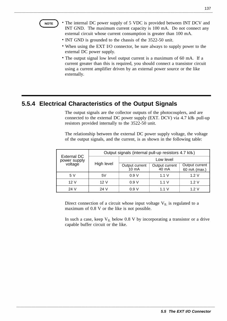
137
5.5 The EXT I/O Connector
NOTE
5.5.4 Electrical Characteristics of the Output Signals
External DCpower supply
voltage
Output signals (internal pull-up resistors 4.7 kΩ)
High levelLow level
Output current10 mA
Output current40 mA
Output current60 mA (max.)
5 V 5V 0.9 V 1.1 V 1.2 V
12 V 12 V 0.9 V 1.1 V 1.2 V
24 V 24 V 0.9 V 1.1 V 1.2 V
The internal DC power supply of 5 VDC is provided between INT DCV andINT GND. The maximum current capacity is 100 mA. Do not connect anyexternal circuit whose current consumption is greater than 100 mA.INT GND is grounded to the chassis of the 3522-50 unit.When using the EXT I/O connector, be sure always to supply power to theexternal DC power supply.The output signal low level output current is a maximum of 60 mA. If acurrent greater than this is required, you should connect a transistor circuitusing a current amplifier driven by an external power source or the likeexternally.
The output signals are the collector outputs of the photocouplers, and areconnected to the external DC power supply (EXT. DCV) via 4.7 kΩ pull-upresistors provided internally to the 3522-50 unit.
The relationship between the external DC power supply voltage, the voltageof the output signals, and the current, is as shown in the following table:
Direct connection of a circuit whose input voltage VIL is regulated to amaximum of 0.8 V or the like is not possible.
In such a case, keep VIL below 0.8 V by incorporating a transistor or a drivecapable buffer circuit or the like.
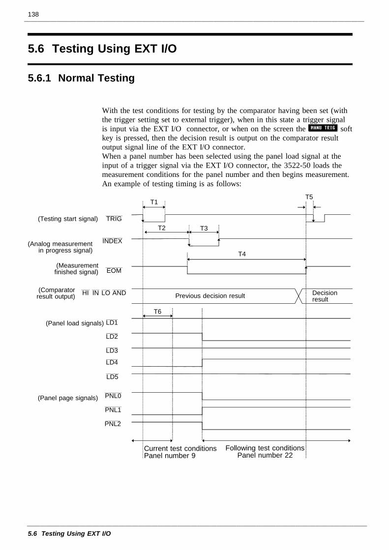
138
5.6 Testing Using EXT I/O
5.6.1 Normal Testing
An example of testing timing is as follows:
T5
T4
T1
T2 T3
DecisionresultPrevious decision result
Current test conditionsPanel number 9
(Panel load signals)
Following test conditionsPanel number 22
T6
(Comparatorresult output)
(Measurementfinished signal)
(Analog measurementin progress signal)
(Testing start signal)
PNL0----------------
PNL1----------------
PNL2--------------
LD1-----------
LD2-----------
LD3-----------
LD4-----------
LD5------------
(Panel page signals)
TRIG----------------
INDEX-------------------
EOM----------------
HI-------- IN------- LO-------- AND-------------
5.6 Testing Using EXT I/O
With the test conditions for testing by the comparator having been set (withthe trigger setting set to external trigger), when in this state a trigger signalis input via the EXT I/O connector, or when on the screen the softkey is pressed, then the decision result is output on the comparator resultoutput signal line of the EXT I/O connector.When a panel number has been selected using the panel load signal at theinput of a trigger signal via the EXT I/O connector, the 3522-50 loads themeasurement conditions for the panel number and then begins measurement.
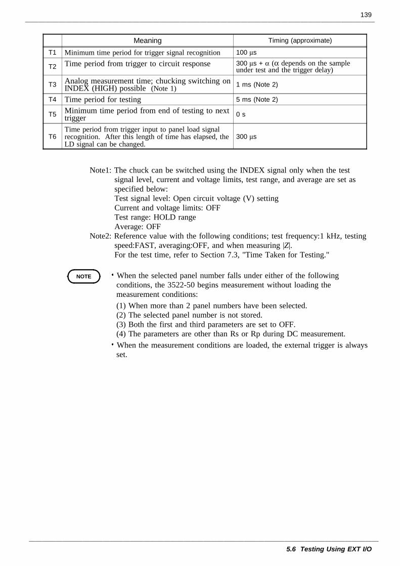
139
5.6 Testing Using EXT I/O
Meaning Timing (approximate)
T1 Minimum time period for trigger signal recognition 100 µs
T2 Time period from trigger to circuit response 300 µs + α (α depends on the sampleunder test and the trigger delay)
T3 Analog measurement time; chucking switching onINDEX (HIGH) possible (Note 1) 1 ms (Note 2)
T4 Time period for testing 5 ms (Note 2)
T5 Minimum time period from end of testing to nexttrigger 0 s
T6Time period from trigger input to panel load signalrecognition. After this length of time has elapsed, theLD signal can be changed.
300 µs
NOTE
Note1: The chuck can be switched using the INDEX signal only when the testsignal level, current and voltage limits, test range, and average are set asspecified below:Test signal level: Open circuit voltage (V) settingCurrent and voltage limits: OFFTest range: HOLD rangeAverage: OFF
Note2: Reference value with the following conditions; test frequency:1 kHz, testingspeed:FAST, averaging:OFF, and when measuring |Z|.For the test time, refer to Section 7.3, "Time Taken for Testing."
When the selected panel number falls under either of the followingconditions, the 3522-50 begins measurement without loading themeasurement conditions:(1) When more than 2 panel numbers have been selected.(2) The selected panel number is not stored.(3) Both the first and third parameters are set to OFF.(4) The parameters are other than Rs or Rp during DC measurement.When the measurement conditions are loaded, the external trigger is alwaysset.
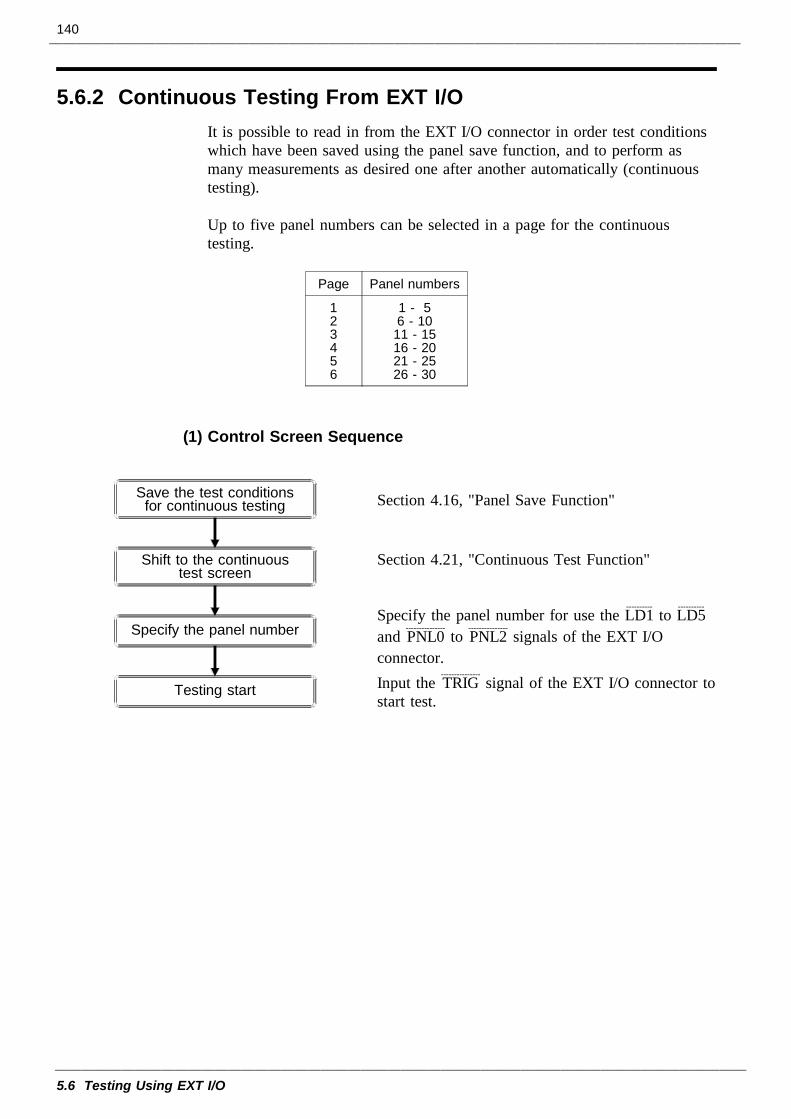
140
5.6 Testing Using EXT I/O
5.6.2 Continuous Testing From EXT I/O
Page Panel numbers
123456
1 - 56 - 1011 - 1516 - 2021 - 2526 - 30
Save the test conditionsfor continuous testing
Testing start
Shift to the continuoustest screen
Specify the panel number
It is possible to read in from the EXT I/O connector in order test conditionswhich have been saved using the panel save function, and to perform asmany measurements as desired one after another automatically (continuoustesting).
Up to five panel numbers can be selected in a page for the continuoustesting.
(1) Control Screen Sequence
Section 4.16, "Panel Save Function"
Section 4.21, "Continuous Test Function"
Specify the panel number for use the LD1----------
to LD5----------
and PNL0---------------
to PNL2---------------
signals of the EXT I/Oconnector.Input the TRIG
---------------signal of the EXT I/O connector to
start test.
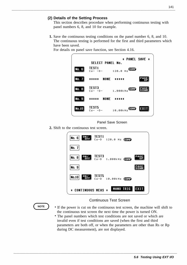
141
5.6 Testing Using EXT I/O
Panel Save Screen
Continuous Test ScreenNOTE
(2) Details of the Setting ProcessThis section describes procedure when performing continuous testing withpanel numbers 6, 8, and 10 for example.
1. Save the continuous testing conditions on the panel number 6, 8, and 10.The continuous testing is performed for the first and third parameters whichhave been saved.For details on panel save function, see Section 4.16.
2. Shift to the continuous test screen.
If the power is cut on the continuous test screen, the machine will shift tothe continuous test screen the next time the power is turned ON.The panel numbers which test conditions are not saved or which areinvalid even if test conditions are saved (when the first and thirdparameters are both off, or when the parameters are other than Rs or Rpduring DC measurement), are not displayed.
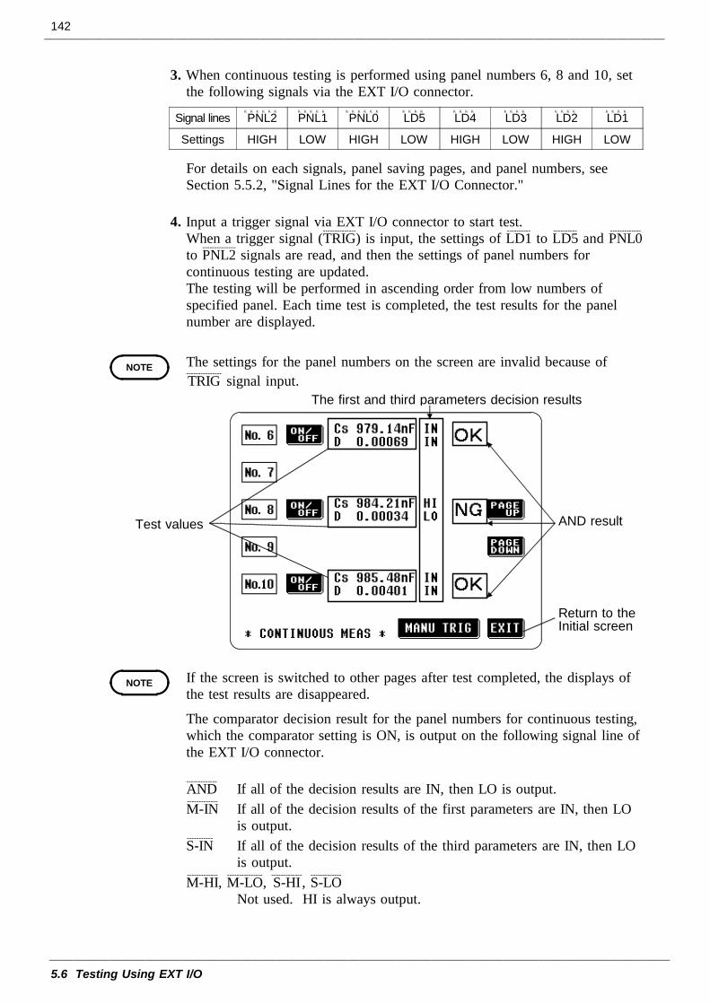
142
5.6 Testing Using EXT I/O
Signal lines PNL2 PNL1 PNL0 LD5 LD4 LD3 LD2 LD1
Settings HIGH LOW HIGH LOW HIGH LOW HIGH LOW
NOTE
Test values AND result
Return to theInitial screen
The first and third parameters decision results
NOTE
3. When continuous testing is performed using panel numbers 6, 8 and 10, setthe following signals via the EXT I/O connector.
For details on each signals, panel saving pages, and panel numbers, seeSection 5.5.2, "Signal Lines for the EXT I/O Connector."
4. Input a trigger signal via EXT I/O connector to start test.When a trigger signal (TRIG
--------------) is input, the settings of LD1
----------to LD5
----------and PNL0
-------------
to PNL2--------------
signals are read, and then the settings of panel numbers forcontinuous testing are updated.The testing will be performed in ascending order from low numbers ofspecified panel. Each time test is completed, the test results for the panelnumber are displayed.
The settings for the panel numbers on the screen are invalid because ofTRIG---------------
signal input.
If the screen is switched to other pages after test completed, the displays ofthe test results are disappeared.
The comparator decision result for the panel numbers for continuous testing,which the comparator setting is ON, is output on the following signal line ofthe EXT I/O connector.
AND-------------
If all of the decision results are IN, then LO is output.M-IN-------------
If all of the decision results of the first parameters are IN, then LOis output.
S-IN-----------
If all of the decision results of the third parameters are IN, then LOis output.
M-HI-------------
, M-LO---------------
, S-HI-------------
, S-LO-------------
Not used. HI is always output.
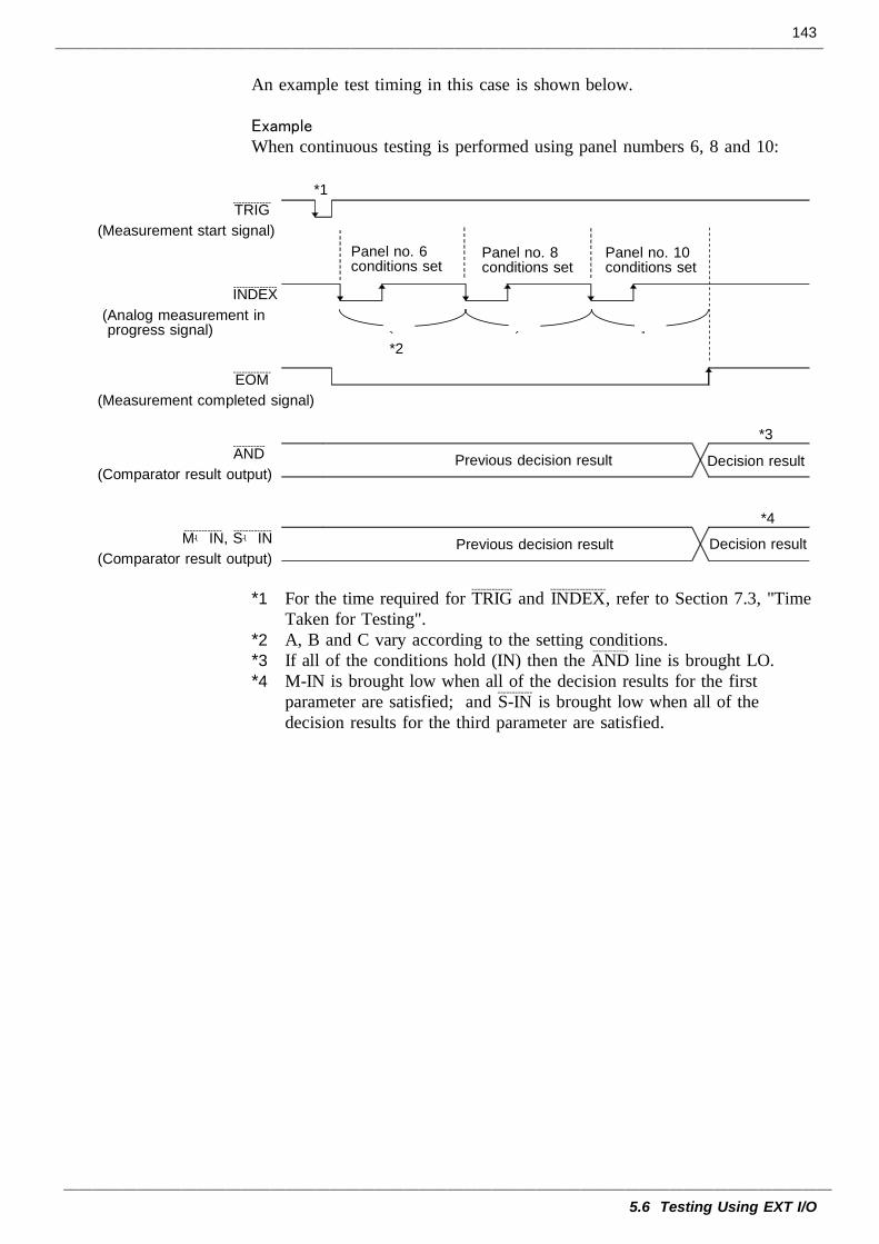
143
5.6 Testing Using EXT I/O
*1
A B C
*2
*3
*4
TRIG-------------
(Measurement start signal)
INDEX---------------
(Analog measurement inprogress signal)
EOM-------------
(Measurement completed signal)
AND-----------
(Comparator result output)
M-IN------------- , S-IN-------------
(Comparator result output)
Panel no. 6conditions set
Panel no. 8conditions set
Panel no. 10conditions set
Decision result
Decision result
Previous decision result
Previous decision result
An example test timing in this case is shown below.
Example When continuous testing is performed using panel numbers 6, 8 and 10:
*1 For the time required for TRIG--------------
and INDEX-------------------
, refer to Section 7.3, "TimeTaken for Testing".
*2 A, B and C vary according to the setting conditions.*3 If all of the conditions hold (IN) then the AND
------------line is brought LO.
*4 M-IN is brought low when all of the decision results for the firstparameter are satisfied; and S-IN
------------is brought low when all of the
decision results for the third parameter are satisfied.
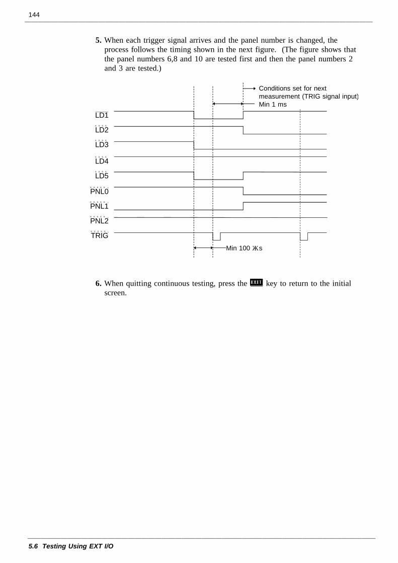
144
5.6 Testing Using EXT I/O
Conditions set for nextmeasurement (TRIG signal input)Min 1 ms
Min 100 μs
LD1------------
LD2
LD3
LD4
LD5
PNL0 -
PNL1 -
PNL2 -
TRIG-
5. When each trigger signal arrives and the panel number is changed, theprocess follows the timing shown in the next figure. (The figure shows thatthe panel numbers 6,8 and 10 are tested first and then the panel numbers 2and 3 are tested.)
6. When quitting continuous testing, press the key to return to the initialscreen.
145
5.7 Supplying DC Bias
CAUTION The maximum voltage which can be applied to the test terminalsof the 3522-50 unit is 10 V DC. If a DC voltage greater than thisis applied continuously, the unit may be damaged.
NOTE
5.7.1 How to Supply a DC Bias Voltage
CAUTION In order to avoid electric shock accident, be absolutely sure not totouch the test terminals while the DC bias voltage is being supplied tothem.If you disconnect the sample under test from the test terminals withthe DC bias voltage still being supplied, then the test sample is leftcharged, which is very dangerous. In order to avoid electric shockaccident, be absolutely sure to discharge the test sample.Do not short circuit between the clips of the test probes with the DCbias voltage still being supplied. Doing so may damage the probes orcause a short circuit accident.
5.7 Supplying DC Bias
Supplying DC bias means that a DC voltage is supplied as a bias to asample for test whose characteristics are voltage dependent, such as anelectrolytic capacitor or a ceramic capacitor.Further, a DC current can be supplied as a bias to a sample for test whosecharacteristics are current dependent, such as a choke coil.Since the 3522-50 unit has no DC bias input terminals, a DC bias must besupplied in the manner described in the following sections.
When the DC bias is supplied to test, and if "OVER FLOW" is displayedand test cannot be done, set the external DC bias function to ON. (SeeSection 4.22, "External DC Bias Setting.")
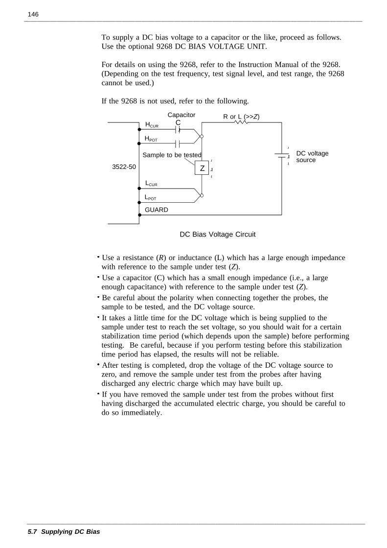
146
5.7 Supplying DC Bias
Z
+ -3522-50
+ -
Sample to be tested DC voltagesource
HPOT
HCUR
LPOT
LCUR
R or L (>>Z)
GUARD
CapacitorC
DC Bias Voltage Circuit
To supply a DC bias voltage to a capacitor or the like, proceed as follows.Use the optional 9268 DC BIAS VOLTAGE UNIT.
For details on using the 9268, refer to the Instruction Manual of the 9268.(Depending on the test frequency, test signal level, and test range, the 9268cannot be used.)
If the 9268 is not used, refer to the following.
Use a resistance (R) or inductance (L) which has a large enough impedancewith reference to the sample under test (Z).Use a capacitor (C) which has a small enough impedance (i.e., a largeenough capacitance) with reference to the sample under test (Z).Be careful about the polarity when connecting together the probes, thesample to be tested, and the DC voltage source.It takes a little time for the DC voltage which is being supplied to thesample under test to reach the set voltage, so you should wait for a certainstabilization time period (which depends upon the sample) before performingtesting. Be careful, because if you perform testing before this stabilizationtime period has elapsed, the results will not be reliable.After testing is completed, drop the voltage of the DC voltage source tozero, and remove the sample under test from the probes after havingdischarged any electric charge which may have built up.If you have removed the sample under test from the probes without firsthaving discharged the accumulated electric charge, you should be careful todo so immediately.
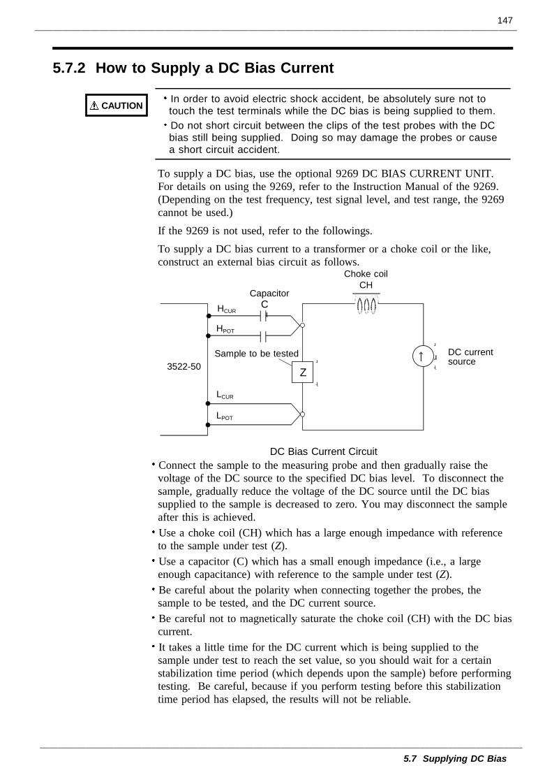
147
5.7 Supplying DC Bias
5.7.2 How to Supply a DC Bias Current
CAUTION In order to avoid electric shock accident, be absolutely sure not totouch the test terminals while the DC bias is being supplied to them.Do not short circuit between the clips of the test probes with the DCbias still being supplied. Doing so may damage the probes or causea short circuit accident.
CapacitorC
↑Z
Choke coilCH
+ -3522-50 +
-
DC currentsource
Sample to be tested
LPOT
LCUR
HPOT
HCUR
DC Bias Current Circuit
To supply a DC bias, use the optional 9269 DC BIAS CURRENT UNIT.For details on using the 9269, refer to the Instruction Manual of the 9269.(Depending on the test frequency, test signal level, and test range, the 9269cannot be used.)If the 9269 is not used, refer to the followings.To supply a DC bias current to a transformer or a choke coil or the like,construct an external bias circuit as follows.
Connect the sample to the measuring probe and then gradually raise thevoltage of the DC source to the specified DC bias level. To disconnect thesample, gradually reduce the voltage of the DC source until the DC biassupplied to the sample is decreased to zero. You may disconnect the sampleafter this is achieved.Use a choke coil (CH) which has a large enough impedance with referenceto the sample under test (Z).Use a capacitor (C) which has a small enough impedance (i.e., a largeenough capacitance) with reference to the sample under test (Z).Be careful about the polarity when connecting together the probes, thesample to be tested, and the DC current source.Be careful not to magnetically saturate the choke coil (CH) with the DC biascurrent.It takes a little time for the DC current which is being supplied to thesample under test to reach the set value, so you should wait for a certainstabilization time period (which depends upon the sample) before performingtesting. Be careful, because if you perform testing before this stabilizationtime period has elapsed, the results will not be reliable.
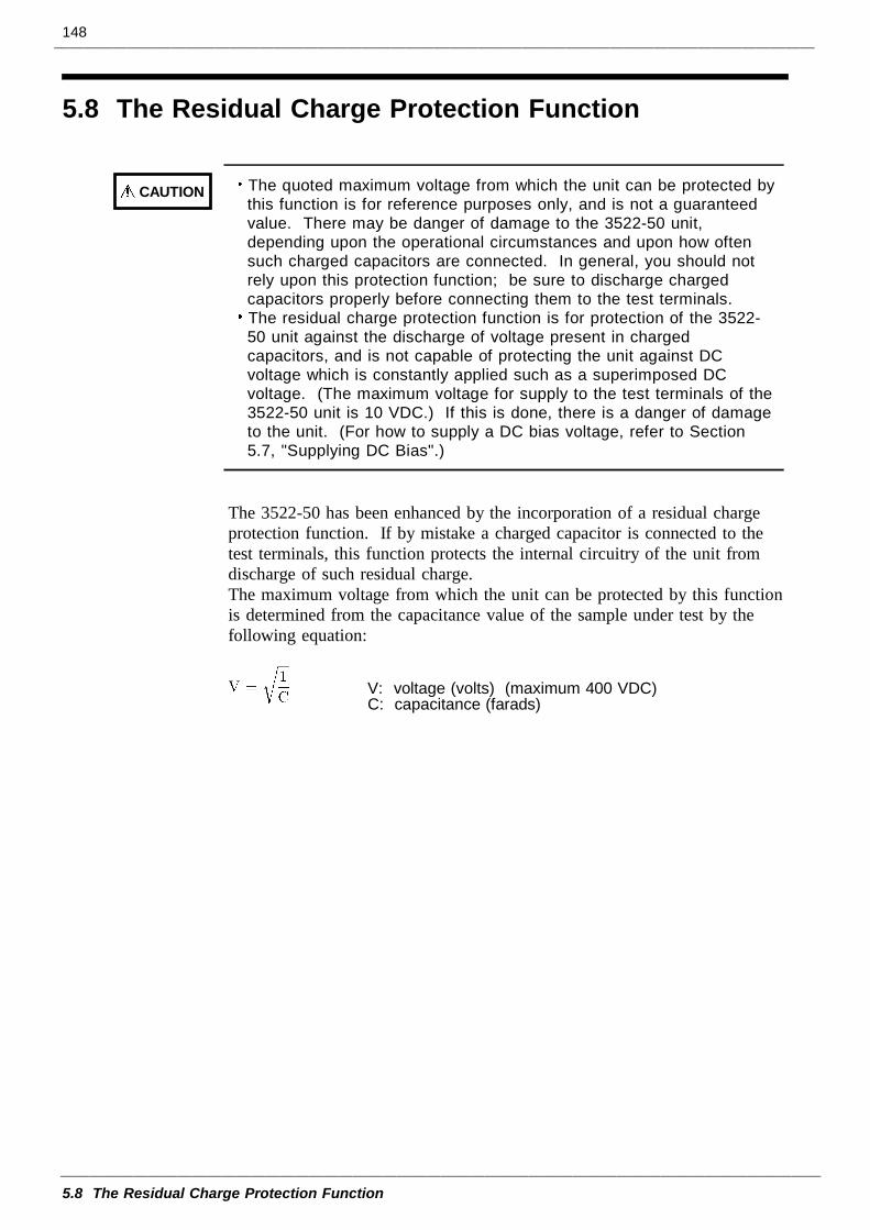
148
5.8 The Residual Charge Protection Function
CAUTION The quoted maximum voltage from which the unit can be protected bythis function is for reference purposes only, and is not a guaranteedvalue. There may be danger of damage to the 3522-50 unit,depending upon the operational circumstances and upon how oftensuch charged capacitors are connected. In general, you should notrely upon this protection function; be sure to discharge chargedcapacitors properly before connecting them to the test terminals.The residual charge protection function is for protection of the 3522-50 unit against the discharge of voltage present in chargedcapacitors, and is not capable of protecting the unit against DCvoltage which is constantly applied such as a superimposed DCvoltage. (The maximum voltage for supply to the test terminals of the3522-50 unit is 10 VDC.) If this is done, there is a danger of damageto the unit. (For how to supply a DC bias voltage, refer to Section5.7, "Supplying DC Bias".)
V: voltage (volts) (maximum 400 VDC)C: capacitance (farads)
5.8 The Residual Charge Protection Function
The 3522-50 has been enhanced by the incorporation of a residual chargeprotection function. If by mistake a charged capacitor is connected to thetest terminals, this function protects the internal circuitry of the unit fromdischarge of such residual charge.The maximum voltage from which the unit can be protected by this functionis determined from the capacitance value of the sample under test by thefollowing equation:
149
5.9 9442 PRINTER (option)
5.9.1 Preparation
CAUTION The 9442 is shipped with the function settings for use with the HIOKI 3166CLAMP ON POWER HiTESTER. Before using, always change the settings ofthe DIP switches.For details on the operations and handling of the printer, refer to theoperation manual supplied to the printer.For the printer, use the 1196 RECORDING PAPER (thermal paper, 10 rolls)or an equivalent.
5.9 9442 PRINTER (option)
Using with the optional 9593-01 RS-232C INTERFACE, 9442 PRINTER,and 9446 CONNECTION CABLE, the test values and screen display copycan be printed out.
(1) Using of the printerUse the 9442 PRINTER, the 9443-01 AC ADAPTER, and the 1196RECORDING PAPER.To connect the main unit and printer, use the 9593-01 RS-232CINTERFACE and the 9446 CONNECTION CABLE. (All are options)9442 DPU-414 Seiko Instruments Inc.9443-01 PW-4007-J1 Seiko Instruments Inc. (for Japan)9443-02 PW-4007-E1 Seiko Instruments Inc. (for EU)9443-03 PW-4007-U1 Seiko Instruments Inc. (for America)
(2) Setting of the 9442 PRINTER communication conditionChange the settings of the software dip switches (DIP SW) to use the 9442for the 3522-50.
1. Turn off the power.2. Turn on the power while pressing the ON LINE button. Release the button
after a list of the current settings starts printing out.3. The print out of the current settings is followed by the prompt:
"Continue? :Push 'On-line SW'", "Write?:Push 'Paper feed SW'".Press the ON LINE button to change the settings.
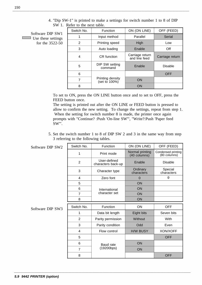
150
5.9 9442 PRINTER (option)
Switch No. Function ON (ON LINE) OFF (FEED)
1 Input method Parallel Serial
2 Printing speed High Low
3 Auto loading Enable Off
4 CR function Carriage returnand line feed Carriage return
5 DIP SW settingcommand Enable Disable
6Printing density(set to 100%)
OFF
7 ON
8 ON
Switch No. Function ON (ON LINE) OFF (FEED)
1 Print mode Normal printing(40 columns)
Condensed printing(80 columns)
2 User-definedcharacters back-up Enable Disable
3 Character type Ordinarycharacters
Specialcharacters
4 Zero font 0 05
Internationalcharacter set
ON6 ON7 ON8 ON
Switch No. Function ON OFF
1 Data bit length Eight bits Seven bits
2 Parity permission Without With
3 Parity condition Odd Even
4 Flow control H/W BUSY XON/XOFF
5
Baud rate(19200bps)
OFF
6 ON
7 ON
8 OFF
4. "Dip SW-1" is printed to make a settings for switch number 1 to 8 of DIPSW 1. Refer to the next table.
Software DIP SW1Use these settings
for the 3522-50
To set to ON, press the ON LINE button once and to set to OFF, press theFEED button once.The setting is printed out after the ON LINE or FEED button is pressed toallow to confirm the new setting. To change the settings, repeat from step 1.When the setting for switch number 8 is made, the printer once again
prompts with "Continue? :Push 'On-line SW'", "Write?:Push 'Paper feedSW'".
5. Set the switch number 1 to 8 of DIP SW 2 and 3 in the same way from step3 referring to the following tables.
Software DIP SW2
Software DIP SW3
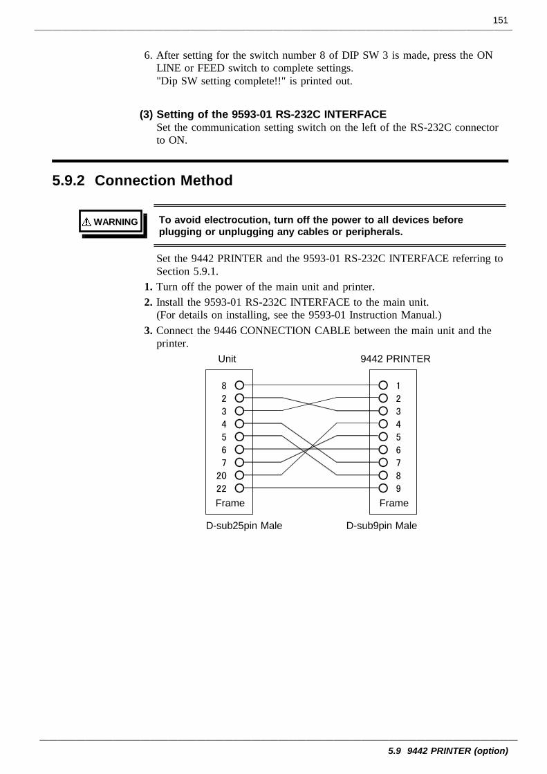
151
5.9 9442 PRINTER (option)
5.9.2 Connection Method
WARNING To avoid electrocution, turn off the power to all devices beforeplugging or unplugging any cables or peripherals.
Unit 9442 PRINTER
Frame Frame
D-sub25pin Male D-sub9pin Male
8 2 3 4 5 6 7
20 22
1
2
3
4
5
6
7
8
9
6. After setting for the switch number 8 of DIP SW 3 is made, press the ONLINE or FEED switch to complete settings."Dip SW setting complete!!" is printed out.
(3) Setting of the 9593-01 RS-232C INTERFACESet the communication setting switch on the left of the RS-232C connectorto ON.
Set the 9442 PRINTER and the 9593-01 RS-232C INTERFACE referring toSection 5.9.1.
1. Turn off the power of the main unit and printer.2. Install the 9593-01 RS-232C INTERFACE to the main unit.
(For details on installing, see the 9593-01 Instruction Manual.)3. Connect the 9446 CONNECTION CABLE between the main unit and the
printer.
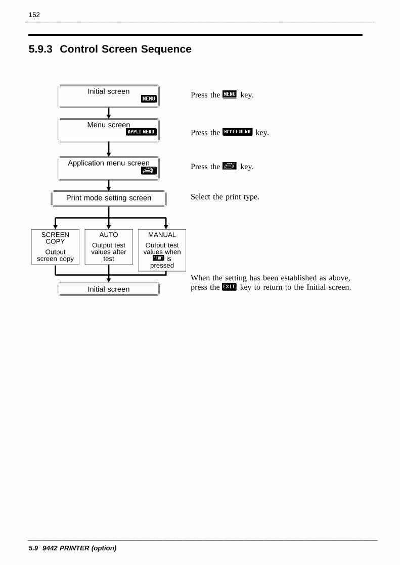
152
5.9 9442 PRINTER (option)
5.9.3 Control Screen Sequence
Initial screen
Initial screen
Menu screen
Application menu screen
Print mode setting screen
SCREENCOPYOutput
screen copy
AUTOOutput testvalues after
test
MANUALOutput test
values whenis
pressed
Press the key.
Press the key.
Press the key.
Select the print type.
When the setting has been established as above,press the key to return to the Initial screen.
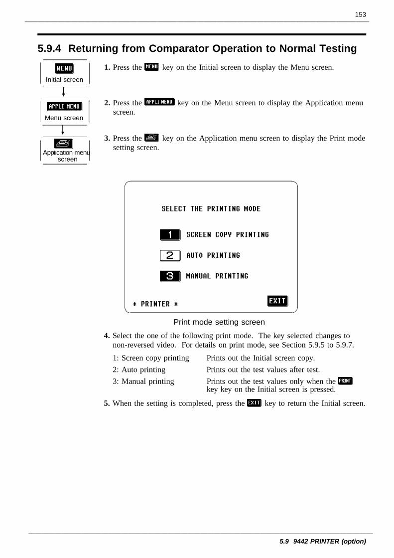
153
5.9 9442 PRINTER (option)
5.9.4 Returning from Comparator Operation to Normal Testing
Initial screen
Menu screen
Application menuscreen
Print mode setting screen
1. Press the key on the Initial screen to display the Menu screen.
2. Press the key on the Menu screen to display the Application menuscreen.
3. Press the key on the Application menu screen to display the Print modesetting screen.
4. Select the one of the following print mode. The key selected changes tonon-reversed video. For details on print mode, see Section 5.9.5 to 5.9.7.1: Screen copy printing Prints out the Initial screen copy.2: Auto printing Prints out the test values after test.3: Manual printing Prints out the test values only when the
key key on the Initial screen is pressed.
5. When the setting is completed, press the key to return the Initial screen.
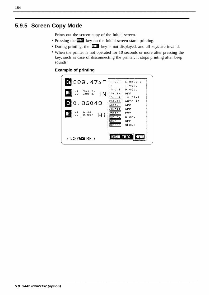
154
5.9 9442 PRINTER (option)
5.9.5 Screen Copy ModePrints out the screen copy of the Initial screen.Pressing the key on the Initial screen starts printing.During printing, the key is not displayed, and all keys are invalid.When the printer is not operated for 10 seconds or more after pressing thekey, such as case of disconnecting the printer, it stops printing after beepsounds.
Example of printing
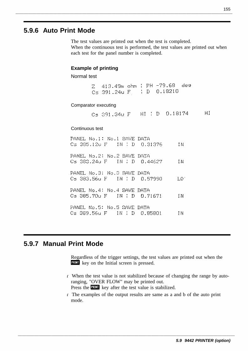
155
5.9 9442 PRINTER (option)
5.9.6 Auto Print Mode
5.9.7 Manual Print Mode
The test values are printed out when the test is completed.When the continuous test is performed, the test values are printed out wheneach test for the panel number is completed.
Example of printingNormal test
Comparator executing
Continuous test
Regardless of the trigger settings, the test values are printed out when thekey on the Initial screen is pressed.
・When the test value is not stabilized because of changing the range by auto-ranging, "OVER FLOW" may be printed out.Press the key after the test value is stabilized.・The examples of the output results are same as a and b of the auto print
mode.
156
5.9 9442 PRINTER (option)
157
6.1 Maintenance and Servicing
1
2
3
4
5
6
7
8
9
10
11
12
13
14
A
NOTE
Chapter 6Maintenance, Adjustment,
and Disposal
6.1 Maintenance and Servicing
In order to use the 3522-50 safely, the following maintenance and checkingprocedures should be executed at the proper intervals.Be sure to read assiduously the various items highlighted in this manual forattention, in order to use the unit correctly.If damage is suspected, check the "Troubleshooting" section beforecontacting your dealer or Hioki representative.Getting the 3522-50 unit wet or letting oil or dust enter inside its casing willcertainly damage it, and is quite likely to cause an electric shock accident ora dangerous conflagration. If the unit has gotten seriously wet, oily, ordusty, stop using it and send it for service at an approved HIOKI servicefacility.Periodic calibration is necessary in order to maintain and authenticate theaccuracy of this testing device. When such calibration is necessary, youshould utilize the services of an approved HIOKI calibration facility.A lithium battery is used in the 3522-50 for powering the backup memory.When this battery becomes unfit for service, it is no longer possible topreserve the testing conditions. Therefore, when it is not possible topreserve the testing conditions, you should dispatch the unit to an approvedHIOKI service facility for the lithium battery to be changed.
HIOKI intend to maintain the supply of spare parts for maintenance andservice of the 3522-50 unit for a minimum of seven years after the cessationof production.
158
6.1 Maintenance and Servicing
Cleaning the unitTo clean the product, wipe it gently with a soft cloth moistened with wateror mild detergent. Never use solvents such as benzene, alcohol, acetone,ether, ketones, thinners or gasoline, as they can deform and discolor thecase.Wipe the LCD gently with a soft, dry cloth.
159
6.2 How to Change the Power Supply Fuse and Change the Power Supply Voltage
1
2
3
4
5
6
7
8
9
10
11
12
13
14
A
WARNING When changing the power supply fuse or changing the powersupply voltage, in order to avoid the risk of electric shock accident,be quite sure first to turn the main switch of the 3522-50 unit off,and then to remove the power cord.Moreover, after finishing any operation, before reconnecting thepower cord to the unit, be sure to check that the power supplyvoltage value indicated on the voltage selector housed in the powerinput socket on the rear panel is in agreement with the actualvoltage value of the power supply line to which you intend toconnect the unit.Replace the fuse only with one of the specified characteristics andvoltage and current ratings. Using a non-specified fuse or shortingthe fuse holder may cause a life-threatening hazard.Fuse type:100 V, 120 V settings: 250 V F1.0 AL 20 mm × 5 mm dia.220 V, 240 V settings: 250 V F0.5 AL 20 mm × 5 mm dia.Before the 3522-50 is dispatched from the factory, it is set to thepower supply voltage used at the destination specified for shipping,and the specified fuse for that power supply voltage is fitted, alongwith an identical spare fuse. If for any reason you intend to powerthe unit from a power supply whose voltage is different, be sure tochange the fuse as well as altering the voltage selector setting.If you intend to use a power supply of a voltage other than thespecified ones for powering the unit, use a fuse and voltageselector setting as follows:Actual power supply voltage 110 V : use settings for 120 VActual power supply voltage 200 V : use settings for 220 VActual power supply voltage 230 V : use settings for 240 V
6.2 How to Change the Power Supply Fuse and Changethe Power Supply Voltage
The power supply fuse for the 3522-50 unit, and the power supply voltageselector, are housed in the power input socket on the rear panel.
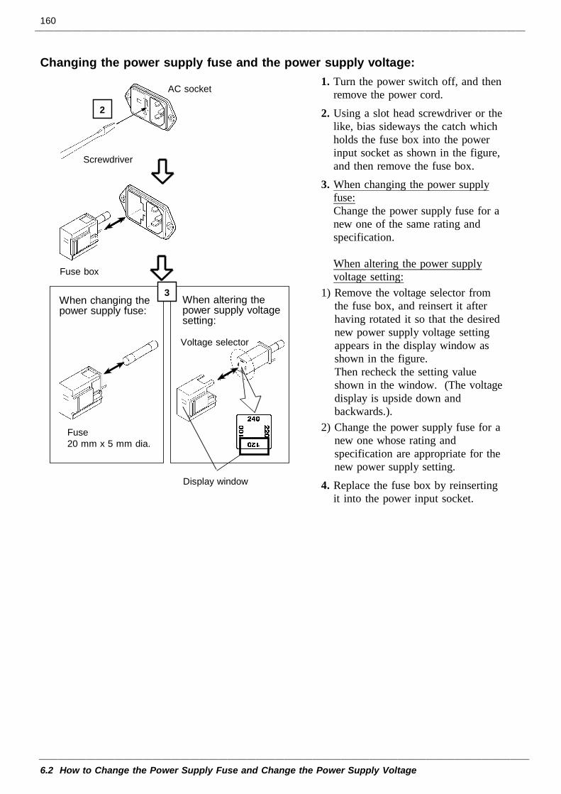
160
6.2 How to Change the Power Supply Fuse and Change the Power Supply Voltage
Screwdriver
AC socket
Display window
When altering thepower supply voltagesetting:
Fuse box
Fuse20 mm x 5 mm dia.
When changing thepower supply fuse:
Voltage selector
2
3
Changing the power supply fuse and the power supply voltage:1. Turn the power switch off, and then
remove the power cord.2. Using a slot head screwdriver or the
like, bias sideways the catch whichholds the fuse box into the powerinput socket as shown in the figure,and then remove the fuse box.
3. When changing the power supplyfuse:Change the power supply fuse for anew one of the same rating andspecification.
When altering the power supplyvoltage setting:
1) Remove the voltage selector fromthe fuse box, and reinsert it afterhaving rotated it so that the desirednew power supply voltage settingappears in the display window asshown in the figure.Then recheck the setting valueshown in the window. (The voltagedisplay is upside down andbackwards.).
2) Change the power supply fuse for anew one whose rating andspecification are appropriate for thenew power supply setting.
4. Replace the fuse box by reinsertingit into the power input socket.
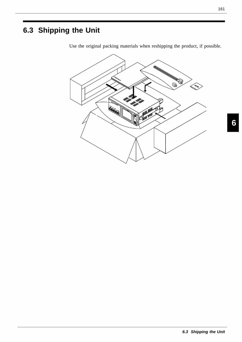
161
6.3 Shipping the Unit
1
2
3
4
5
6
7
8
9
10
11
12
13
14
A
6.3 Shipping the Unit
Use the original packing materials when reshipping the product, if possible.
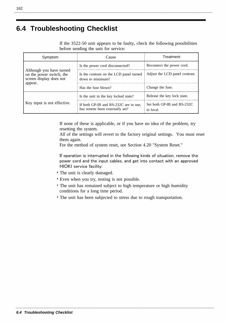
162
6.4 Troubleshooting Checklist
Symptom Cause Treatment
Although you have turnedon the power switch, thescreen display does notappear.
Is the power cord disconnected? Reconnect the power cord.
Is the contrast on the LCD panel turneddown to minimum?
Adjust the LCD panel contrast.
Has the fuse blown? Change the fuse.
Key input is not effective.Is the unit in the key locked state? Release the key lock state.
If both GP-IB and RS-232C are in use,has remote been externally set?
Set both GP-IB and RS-232Cto local.
6.4 Troubleshooting Checklist
If the 3522-50 unit appears to be faulty, check the following possibilitiesbefore sending the unit for service:
If none of these is applicable, or if you have no idea of the problem, tryresetting the system.All of the settings will revert to the factory original settings. You must resetthem again.For the method of system reset, see Section 4.20 "System Reset."
If operation is interrupted in the following kinds of situation, remove thepower cord and the input cables, and get into contact with an approvedHIOKI service facility:
The unit is clearly damaged.Even when you try, testing is not possible.The unit has remained subject to high temperature or high humidityconditions for a long time period.The unit has been subjected to stress due to rough transportation.
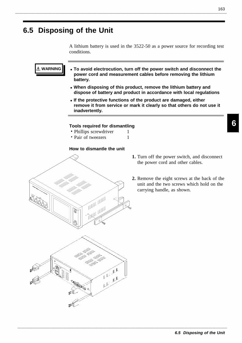
163
6.5 Disposing of the Unit
1
2
3
4
5
6
7
8
9
10
11
12
13
14
A
WARNING To avoid electrocution, turn off the power switch and disconnect thepower cord and measurement cables before removing the lithiumbattery.When disposing of this product, remove the lithium battery anddispose of battery and product in accordance with local regulationsIf the protective functions of the product are damaged, eitherremove it from service or mark it clearly so that others do not use itinadvertently.
6.5 Disposing of the Unit
A lithium battery is used in the 3522-50 as a power source for recording testconditions.
Tools required for dismantlingPhillips screwdriver 1Pair of tweezers 1
How to dismantle the unit1. Turn off the power switch, and disconnect
the power cord and other cables.
2. Remove the eight screws at the back of theunit and the two screws which hold on thecarrying handle, as shown.
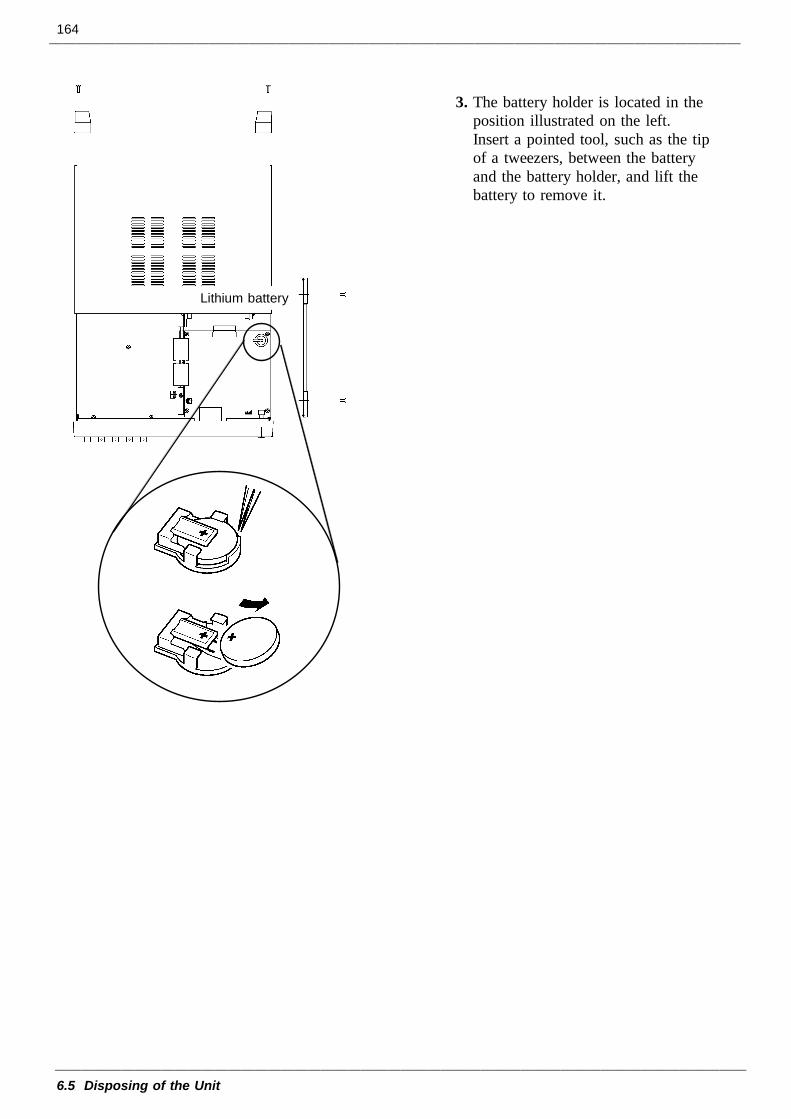
164
6.5 Disposing of the Unit
Lithium battery
3. The battery holder is located in theposition illustrated on the left.Insert a pointed tool, such as the tipof a tweezers, between the batteryand the battery holder, and lift thebattery to remove it.
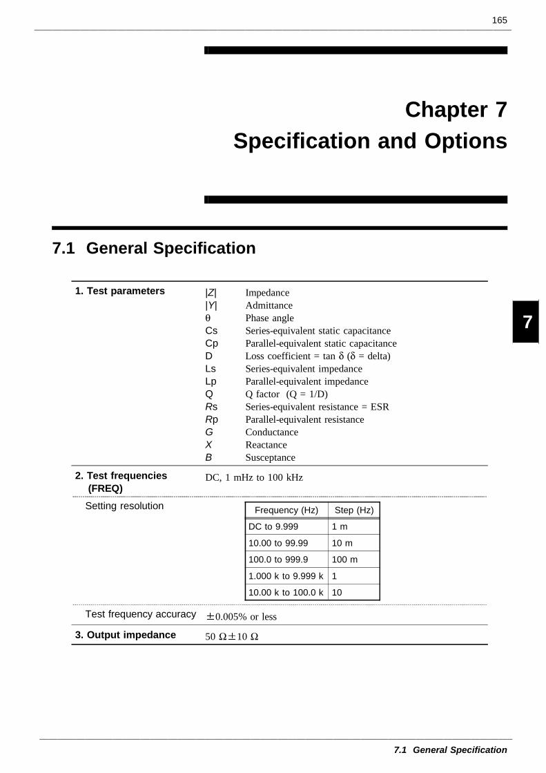
165
7.1 General Specification
1
2
3
4
5
6
7
8
9
10
11
12
13
14
A
1. Test parameters |Z||Y|θCsCpDLsLpQRsRpGXB
ImpedanceAdmittancePhase angleSeries-equivalent static capacitanceParallel-equivalent static capacitanceLoss coefficient = tan δ (δ = delta)Series-equivalent impedanceParallel-equivalent impedanceQ factor (Q = 1/D)Series-equivalent resistance = ESRParallel-equivalent resistanceConductanceReactanceSusceptance
2. Test frequencies(FREQ)
DC, 1 mHz to 100 kHz
Setting resolution Frequency (Hz) Step (Hz)
DC to 9.999 1 m
10.00 to 99.99 10 m
100.0 to 999.9 100 m
1.000 k to 9.999 k 1
10.00 k to 100.0 k 10
Test frequency accuracy 0.005% or less
3. Output impedance 50 Ω 10 Ω
Chapter 7Specification and Options
7.1 General Specification
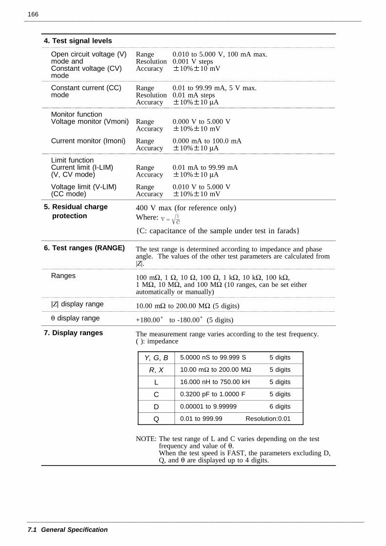
166
7.1 General Specification
4. Test signal levels
Open circuit voltage (V)mode andConstant voltage (CV)mode
Range 0.010 to 5.000 V, 100 mA max.Resolution 0.001 V stepsAccuracy 10% 10 mV
Constant current (CC)mode
Range 0.01 to 99.99 mA, 5 V max.Resolution 0.01 mA stepsAccuracy 10% 10 µA
Monitor functionVoltage monitor (Vmoni) Range 0.000 V to 5.000 V
Accuracy 10% 10 mV
Current monitor (Imoni) Range 0.000 mA to 100.0 mAAccuracy 10% 10 µA
Limit functionCurrent limit (I-LIM)(V, CV mode)
Range 0.01 mA to 99.99 mAAccuracy 10% 10 µA
Voltage limit (V-LIM)(CC mode)
Range 0.010 V to 5.000 VAccuracy 10% 10 mV
5. Residual chargeprotection
400 V max (for reference only)Where:
C: capacitance of the sample under test in farads
6. Test ranges (RANGE) The test range is determined according to impedance and phaseangle. The values of the other test parameters are calculated from|Z|.
Ranges 100 mΩ, 1 Ω, 10 Ω, 100 Ω, 1 kΩ, 10 kΩ, 100 kΩ,1 MΩ, 10 MΩ, and 100 MΩ (10 ranges, can be set eitherautomatically or manually)
|Z| display range 10.00 mΩ to 200.00 MΩ (5 digits)
θ display range +180.00 to -180.00 (5 digits)
7. Display ranges The measurement range varies according to the test frequency.( ): impedance
Y, G, B 5.0000 nS to 99.999 S 5 digits
R, X 10.00 mΩ to 200.00 MΩ 5 digits
L 16.000 nH to 750.00 kH 5 digits
C 0.3200 pF to 1.0000 F 5 digits
D 0.00001 to 9.99999 6 digits
Q 0.01 to 999.99 Resolution:0.01
NOTE: The test range of L and C varies depending on the testfrequency and value of θ.When the test speed is FAST, the parameters excluding D,Q, and θ are displayed up to 4 digits.
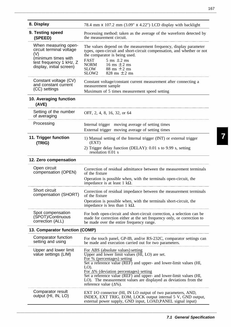
167
7.1 General Specification
1
2
3
4
5
6
7
8
9
10
11
12
13
14
A
8. Display 78.4 mm x 107.2 mm (3.09" x 4.22") LCD display with backlight
9. Testing speed(SPEED)
Processing method: taken as the average of the waveform detected bythe measurement circuit.
When measuring open-circuit terminal voltage(V)(minimum times withtest frequency 1 kHz, Zdisplay, initial screen)
The values depend on the measurement frequency, display parametertypes, open-circuit and short-circuit compensation, and whether or notthe comparator is being used.FAST 5 ms 2 msNORM 16 ms 2 msSLOW 88 ms 2 msSLOW2 828 ms 2 ms
Constant voltage (CV)and constant current(CC) settings
Constant voltage/constant current measurement after connecting ameasurement sampleMaximum of 5 times measurement speed setting
10. Averaging function(AVE)
Setting of the numberof averaging
OFF, 2, 4, 8, 16, 32, or 64
Processing Internal trigger moving average of setting timesExternal trigger moving average of setting times
11. Trigger function(TRIG)
1) Manual setting of the Internal trigger (INT) or external trigger(EXT)
2) Trigger delay function (DELAY): 0.01 s to 9.99 s, settingresolution 0.01 s
12. Zero compensation
Open circuitcompensation (OPEN)
Correction of residual admittance between the measurement terminalsof the fixtureOperation is possible when, with the terminals open-circuit, theimpedance is at least 1 kΩ.
Short circuitcompensation (SHORT)
Correction of residual impedance between the measurement terminalsof the fixtureOperation is possible when, with the terminals short-circuit, theimpedance is less than 1 kΩ.
Spot compensation(SPOT)/Continuouscorrection (ALL)
For both open-circuit and short-circuit correction, a selection can bemade for correction either at the set frequency only, or correction tobe made over the entire frequency range.
13. Comparator function (COMP)Comparator functionsetting and using
For the touch panel, GP-IB, and/or RS-232C, comparator settings canbe made and execution carried out for two parameters.
Upper and lower limitvalue settings (LIM)
For ABS (absolute values) settingUpper and lower limit values (HI, LO) are set.For % (percentages) settingSet a reference value (REF) and upper- and lower-limit values (HI,LO).For ∆% (deviation percentages) settingSet a reference value (REF) and upper- and lower-limit values (HI,LO). The measurement values are displayed as deviations from thereference value (∆%).
Comparator resultoutput (HI, IN, LO)
EXT I/O connector (HI, IN LO output of two parameters, AND,INDEX, EXT TRIG, EOM, LOCK output internal 5 V, GND output,external power supply, GND input, LOAD,PANEL signal input)
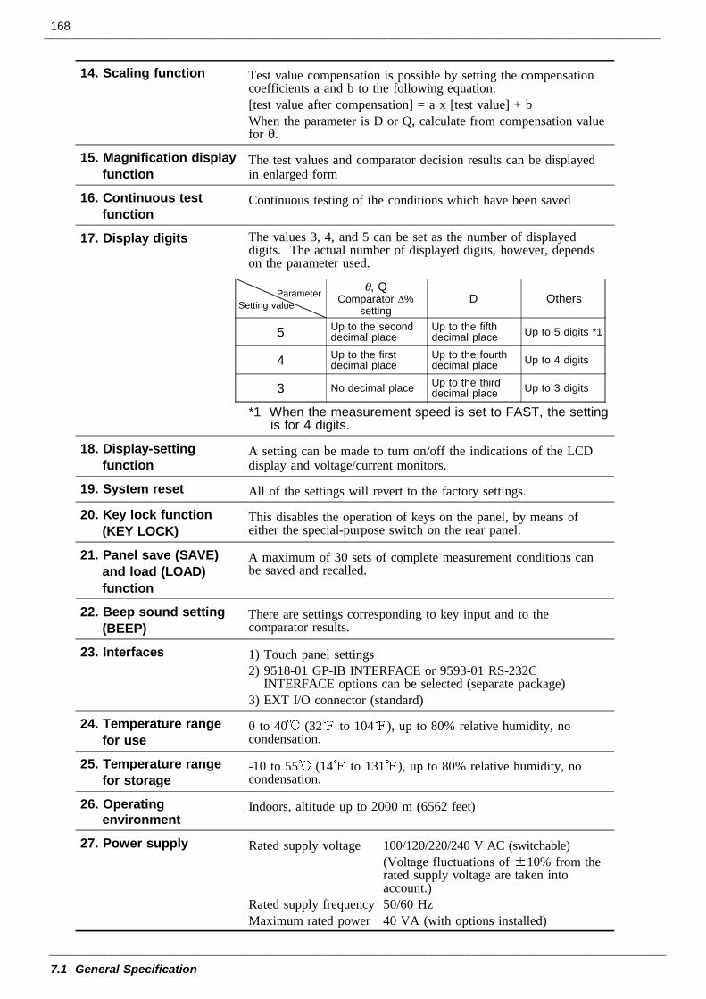
168
7.1 General Specification
14. Scaling function Test value compensation is possible by setting the compensationcoefficients a and b to the following equation.[test value after compensation] = a x [test value] + bWhen the parameter is D or Q, calculate from compensation valuefor θ.
15. Magnification displayfunction
The test values and comparator decision results can be displayedin enlarged form
16. Continuous testfunction
Continuous testing of the conditions which have been saved
17. Display digits The values 3, 4, and 5 can be set as the number of displayeddigits. The actual number of displayed digits, however, dependson the parameter used.
ParameterSetting value
θ, QComparator ∆%
settingD Others
5 Up to the seconddecimal place
Up to the fifthdecimal place Up to 5 digits *1
4 Up to the firstdecimal place
Up to the fourthdecimal place Up to 4 digits
3 No decimal place Up to the thirddecimal place Up to 3 digits
*1 When the measurement speed is set to FAST, the settingis for 4 digits.
18. Display-settingfunction
A setting can be made to turn on/off the indications of the LCDdisplay and voltage/current monitors.
19. System reset All of the settings will revert to the factory settings.
20. Key lock function(KEY LOCK)
This disables the operation of keys on the panel, by means ofeither the special-purpose switch on the rear panel.
21. Panel save (SAVE)and load (LOAD)function
A maximum of 30 sets of complete measurement conditions canbe saved and recalled.
22. Beep sound setting(BEEP)
There are settings corresponding to key input and to thecomparator results.
23. Interfaces 1) Touch panel settings2) 9518-01 GP-IB INTERFACE or 9593-01 RS-232C
INTERFACE options can be selected (separate package)3) EXT I/O connector (standard)
24. Temperature rangefor use
0 to 40 (32 to 104 ), up to 80% relative humidity, nocondensation.
25. Temperature rangefor storage
-10 to 55 (14 to 131 ), up to 80% relative humidity, nocondensation.
26. Operatingenvironment
Indoors, altitude up to 2000 m (6562 feet)
27. Power supply Rated supply voltage 100/120/220/240 V AC (switchable)(Voltage fluctuations of 10% from therated supply voltage are taken intoaccount.)
Rated supply frequency 50/60 HzMaximum rated power 40 VA (with options installed)
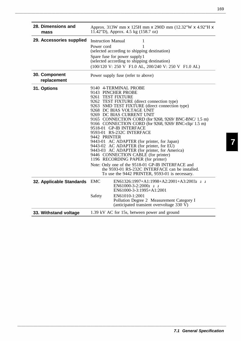
169
7.1 General Specification
1
2
3
4
5
6
7
8
9
10
11
12
13
14
A
28. Dimensions andmass
Approx. 313W mm x 125H mm x 290D mm (12.32"W x 4.92"H x11.42"D), Approx. 4.5 kg (158.7 oz)
29. Accessories supplied Instruction Manual 1Power cord 1(selected according to shipping destination)Spare fuse for power supply 1(selected according to shipping destination)(100/120 V: 250 V F1.0 AL, 200/240 V: 250 V F1.0 AL)
30. Componentreplacement
Power supply fuse (refer to above)
31. Options 9140 4-TERMINAL PROBE9143 PINCHER PROBE9261 TEST FIXTURE9262 TEST FIXTURE (direct connection type)9263 SMD TEST FIXTURE (direct connection type)9268 DC BIAS VOLTAGE UNIT9269 DC BIAS CURRENT UNIT9165 CONNECTION CORD (for 9268, 9269/ BNC-BNC/ 1.5 m)9166 CONNECTION CORD (for 9268, 9269/ BNC-clip/ 1.5 m)9518-01 GP-IB INTERFACE9593-01 RS-232C INTERFACE9442 PRINTER9443-01 AC ADAPTER (for printer, for Japan)9443-02 AC ADAPTER (for printer, for EU)9443-03 AC ADAPTER (for printer, for America)9446 CONNECTION CABLE (for printer)1196 RECORDING PAPER (for printer)Note: Only one of the 9518-01 GP-IB INTERFACE and
the 9593-01 RS-232C INTERFACE can be installed.To use the 9442 PRINTER, 9593-01 is necessary.
32. Applicable Standards EMC EN61326:1997+A1:1998+A2:2001+A3:2003 EN61000-3-2:2000 EN61000-3-3:1995+A1:2001Safety EN61010-1:2001 Pollution Degree 2 Measurement Category I (anticipated transient overvoltage 330 V)
33. Withstand voltage 1.39 kV AC for 15s, between power and ground
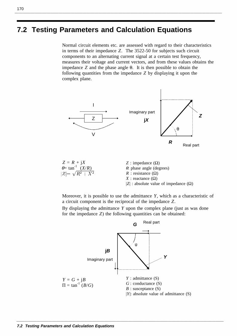
170
7.2 Testing Parameters and Calculation Equations
Z
Real part
Imaginary part
R
jXZ
I
Vθ
Z : impedance (Ω) θ: phase angle (degrees)R : resistance (Ω)X : reactance (Ω)|Z| : absolute value of impedance (Ω)
Real part
Imaginary part
jB
G
Y
φ
Y : admittance (S)G : conductance (S)B : susceptance (S)|Y |: absolute value of admittance (S)
7.2 Testing Parameters and Calculation Equations
Normal circuit elements etc. are assessed with regard to their characteristicsin terms of their impedance Z. The 3522-50 for subjects such circuitcomponents to an alternating current signal at a certain test frequency,measures their voltage and current vectors, and from these values obtains theimpedance Z and the phase angle θ. It is then possible to obtain thefollowing quantities from the impedance Z by displaying it upon thecomplex plane.
Z = R + jXθ= tan-1 (X/R)
Moreover, it is possible to use the admittance Y, which as a characteristic ofa circuit component is the reciprocal of the impedance Z.By displaying the admittance Y upon the complex plane (just as was donefor the impedance Z) the following quantities can be obtained:
Y = G + jBφ= tan-1 (B/G)
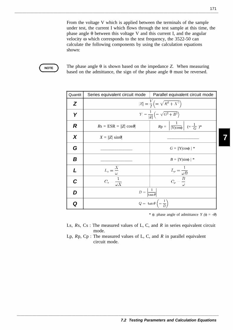
171
7.2 Testing Parameters and Calculation Equations
1
2
3
4
5
6
7
8
9
10
11
12
13
14
A
NOTE
Quantit Series equivalent circuit mode Parallel equivalent circuit mode
Z
Y
R Rs = ESR = ||Z| cosθ| Rp =1
|Y|cosφ (= )*1G
X X = ||Z| sinθ| ________________
G ________________ G = ||Y|cosφ | *
B ________________ B = ||Y|sinφ | *
L
C
D
Q
* φ: phase angle of admittance Y (φ = -θ)
From the voltage V which is applied between the terminals of the sampleunder test, the current I which flows through the test sample at this time, thephase angle θ between this voltage V and this current I, and the angularvelocity ω which corresponds to the test frequency, the 3522-50 cancalculate the following components by using the calculation equationsshown:
The phase angle θ is shown based on the impedance Z. When measuringbased on the admittance, the sign of the phase angle θ must be reversed.
Ls, Rs, Cs : The measured values of L, C, and R in series equivalent circuitmode.
Lp, Rp, Cp : The measured values of L, C, and R in parallel equivalentcircuit mode.
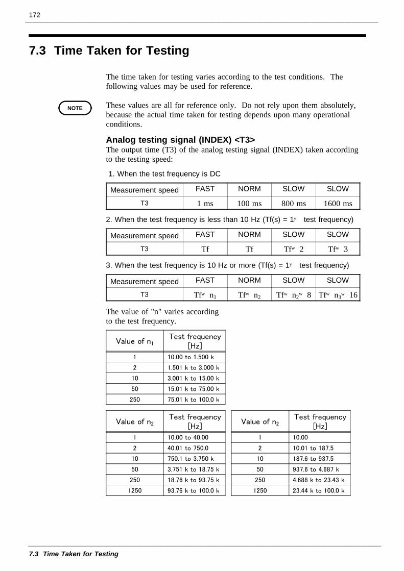
172
7.3 Time Taken for Testing
NOTE
1. When the test frequency is DC
Measurement speed FAST NORM SLOW SLOW
T3 1 ms 100 ms 800 ms 1600 ms
2. When the test frequency is less than 10 Hz (Tf(s) = 1÷ test frequency)
Measurement speed FAST NORM SLOW SLOW
T3 Tf Tf Tf×2 Tf×3
3. When the test frequency is 10 Hz or more (Tf(s) = 1÷ test frequency)
Measurement speed FAST NORM SLOW SLOW
T3 Tf×n1 Tf×n2 Tf×n2×8 Tf×n3×16
The value of "n" varies accordingto the test frequency.
Value of n1Test frequency
[Hz]
1 10.00 to 1.500 k
2 1.501 k to 3.000 k
10 3.001 k to 15.00 k
50 15.01 k to 75.00 k
250 75.01 k to 100.0 k
Value of n2Test frequency
[Hz]
1 10.00 to 40.00
2 40.01 to 750.0
10 750.1 to 3.750 k
50 3.751 k to 18.75 k
250 18.76 k to 93.75 k
1250 93.76 k to 100.0 k
Value of n2Test frequency
[Hz]
1 10.00
2 10.01 to 187.5
10 187.6 to 937.5
50 937.6 to 4.687 k
250 4.688 k to 23.43 k
1250 23.44 k to 100.0 k
7.3 Time Taken for Testing
The time taken for testing varies according to the test conditions. Thefollowing values may be used for reference.
These values are all for reference only. Do not rely upon them absolutely,because the actual time taken for testing depends upon many operationalconditions.
Analog testing signal (INDEX) <T3>The output time (T3) of the analog testing signal (INDEX) taken accordingto the testing speed:
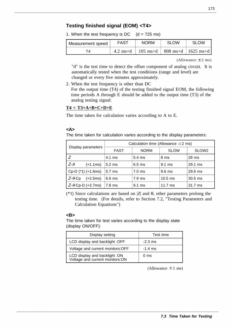
173
7.3 Time Taken for Testing
1. When the test frequency is DC (d = 725 ms)
Measurement speed FAST NORM SLOW SLOW
T4 4.2 ms+d 105 ms+d 808 ms+d 1625 ms+d
(Allowance 2 ms)
<A>The time taken for calculation varies according to the display parameters:
Display parametersCalculation time (Allowance 2 ms)
FAST NORM SLOW SLOW2
Z 4.1 ms 5.4 ms 8 ms 28 ms
Z-θ (+1.1ms) 5.2 ms 6.5 ms 9.1 ms 29.1 ms
Cp-D (*1) (+1.6ms) 5.7 ms 7.0 ms 9.6 ms 29.6 ms
Z-θ-Cp (+2.5ms) 6.6 ms 7.9 ms 10.5 ms 30.5 ms
Z-θ-Cp-D (+3.7ms) 7.8 ms 9.1 ms 11.7 ms 31.7 ms
<B>The time taken for test varies according to the display state(display ON/OFF):
Display setting Test time
LCD display and backlight :OFF -2.3 ms
Voltage and current monitors:OFF -1.4 ms
LCD display and backlight :ONVoltage and current monitors:ON
0 ms
(Allowance 1 ms)
Testing finished signal (EOM) <T4>
"d" is the test time to detect the offset component of analog circuit. It isautomatically tested when the test conditions (range and level) arechanged or every five minutes approximately.
2. When the test frequency is other than DCFor the output time (T4) of the testing finished signal EOM, the followingtime periods A through E should be added to the output time (T3) of theanalog testing signal:
T4 = T3+A+B+C+D+EThe time taken for calculation varies according to A to E.
(*1) Since calculations are based on |Z| and θ, other parameters prolong thetesting time. (For details, refer to Section 7.2, "Testing Parameters andCalculation Equations")
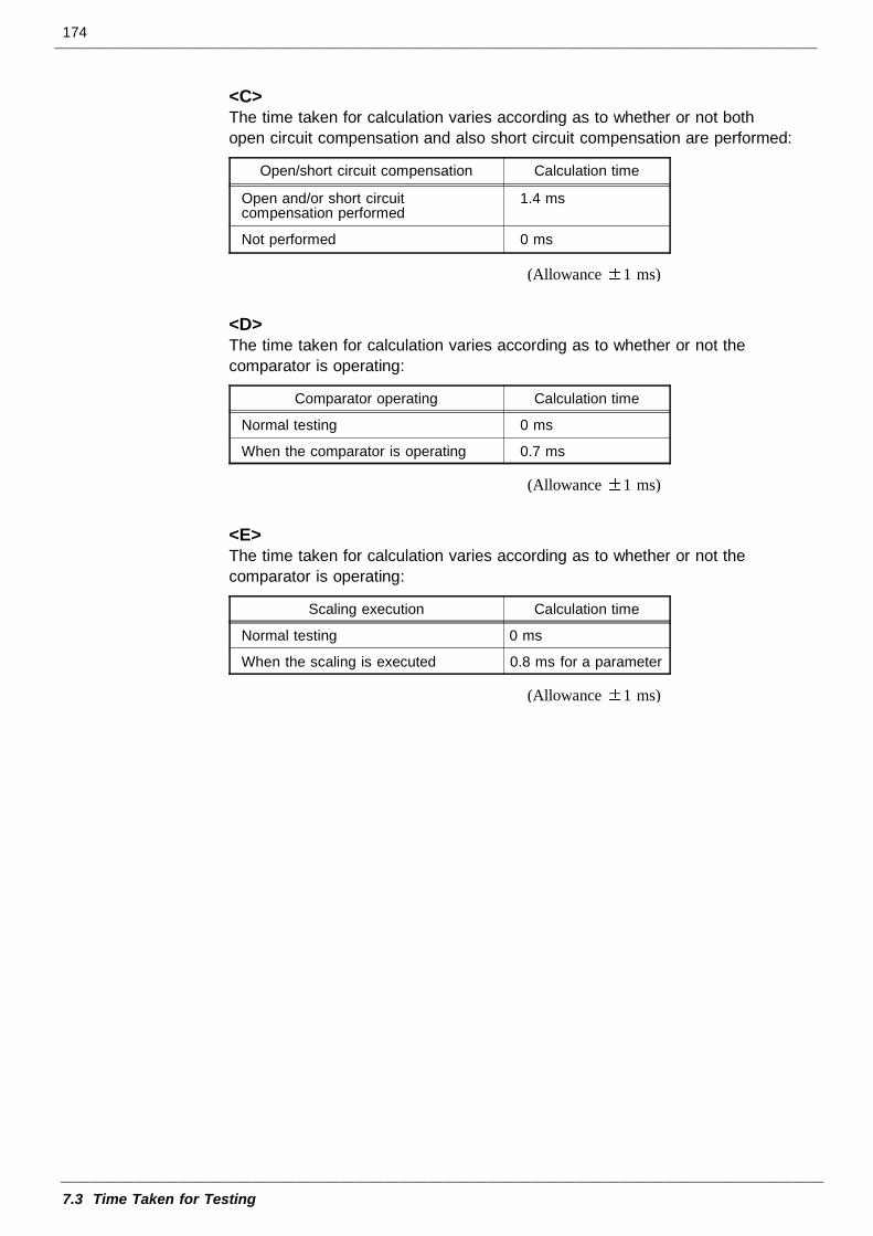
174
7.3 Time Taken for Testing
<C>The time taken for calculation varies according as to whether or not bothopen circuit compensation and also short circuit compensation are performed:
Open/short circuit compensation Calculation time
Open and/or short circuitcompensation performed
1.4 ms
Not performed 0 ms
(Allowance 1 ms)
<D>The time taken for calculation varies according as to whether or not thecomparator is operating:
Comparator operating Calculation time
Normal testing 0 ms
When the comparator is operating 0.7 ms
(Allowance 1 ms)
<E>The time taken for calculation varies according as to whether or not thecomparator is operating:
Scaling execution Calculation time
Normal testing 0 ms
When the scaling is executed 0.8 ms for a parameter
(Allowance 1 ms)
175
7.3 Time Taken for Testing
Range Frequency1 DC
2 0.001 Hz to 0.100 Hz
3 0.101 Hz to 4.000 Hz
4 4.001 Hz to 100.0 Hz
5 100.1 Hz to 2.000 kHz
6 2.001 kHz to 10.00 kHz
7 10.01 kHz to 100.0 kHz
Range Test signal level1 0.010 V to 0.200 V
2 0.201 V to 0.500 V
3 0.501 V to 1.000 V
4 1.001 V to 2.000 V
5 2.001 V to 2.500 V
6 2.501 V to 5.000 V
Wait time for changing test conditionsWhen the test conditions are changed, the time taken for the internalprocessing is necessary according to the following factors (1) to (4), beforetesting.If the several factors occur the wait time, the longest time is taken amongthe factors.
(1) When the test frequency is changed:Changing to the frequency in another range Wait time: 300 msChanging the frequency through 100.1 Hz Wait time: 1s
Example: When the test frequency is changed from 10 Hz to 1 kHz, the waittime is 1s.
(2) When the test signal level is changed:Changing to the test signal level in another range Wait time: 300 ms
Example: When the test signal level is changed from 1 V to 1.001 V, thewait time is 300 ms.
Note: When the test signal level setting is CV/CC or the setting of voltageand current limit is ON, the test signal level is automaticallychanged.
(3) When the test range is changed:There are cases in which a 300 ms wait is entered.
(4) When the setting for external DC bias is changed:There are cases in which a 300 ms or a 1 s wait is entered.
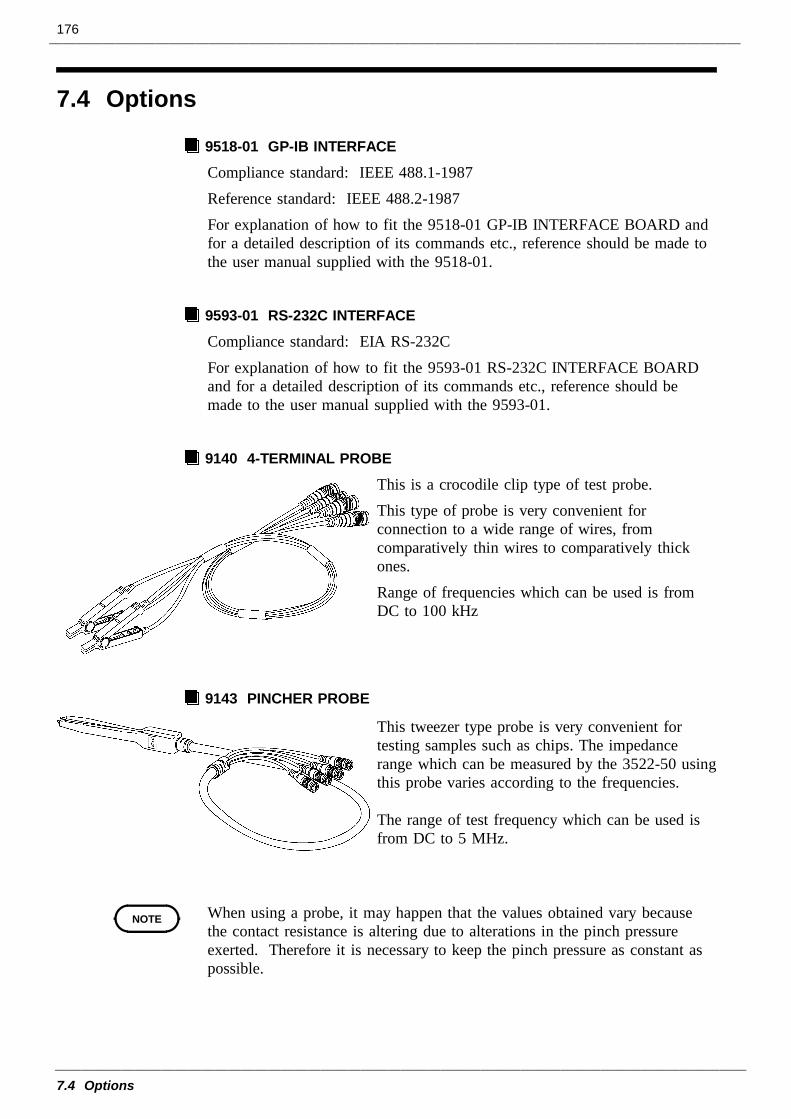
176
7.4 Options
NOTE
7.4 Options
9518-01 GP-IB INTERFACE
Compliance standard: IEEE 488.1-1987Reference standard: IEEE 488.2-1987For explanation of how to fit the 9518-01 GP-IB INTERFACE BOARD andfor a detailed description of its commands etc., reference should be made tothe user manual supplied with the 9518-01.
9593-01 RS-232C INTERFACE
Compliance standard: EIA RS-232CFor explanation of how to fit the 9593-01 RS-232C INTERFACE BOARDand for a detailed description of its commands etc., reference should bemade to the user manual supplied with the 9593-01.
9140 4-TERMINAL PROBE
This is a crocodile clip type of test probe.This type of probe is very convenient forconnection to a wide range of wires, fromcomparatively thin wires to comparatively thickones.Range of frequencies which can be used is fromDC to 100 kHz
9143 PINCHER PROBE
This tweezer type probe is very convenient fortesting samples such as chips. The impedancerange which can be measured by the 3522-50 usingthis probe varies according to the frequencies.
The range of test frequency which can be used isfrom DC to 5 MHz.
When using a probe, it may happen that the values obtained vary becausethe contact resistance is altering due to alterations in the pinch pressureexerted. Therefore it is necessary to keep the pinch pressure as constant aspossible.
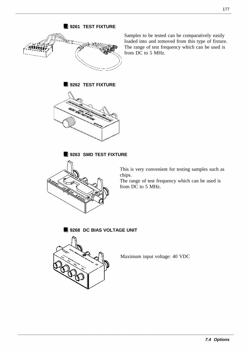
177
7.4 Options
9261 TEST FIXTURE
Samples to be tested can be comparatively easilyloaded into and removed from this type of fixture.The range of test frequency which can be used isfrom DC to 5 MHz.
9262 TEST FIXTURE
9263 SMD TEST FIXTURE
This is very convenient for testing samples such aschips.The range of test frequency which can be used isfrom DC to 5 MHz.
9268 DC BIAS VOLTAGE UNIT
Maximum input voltage: 40 VDC
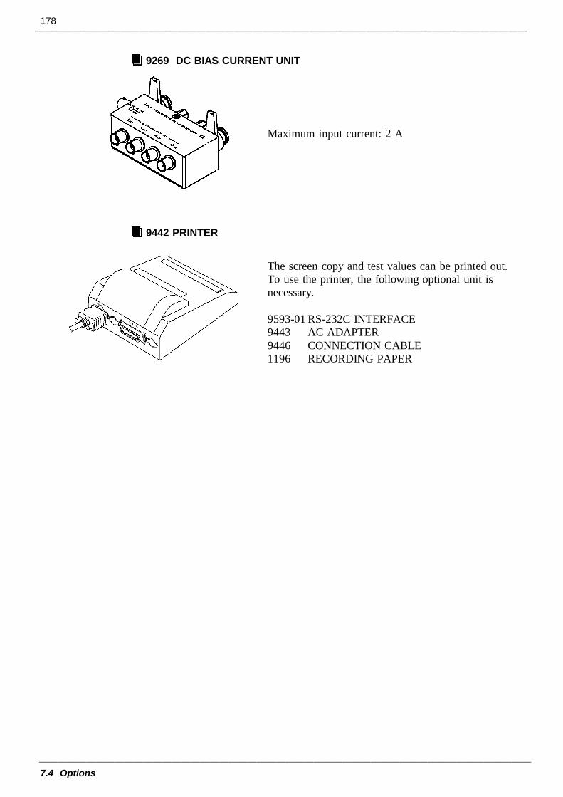
178
7.4 Options
9269 DC BIAS CURRENT UNIT
Maximum input current: 2 A
9442 PRINTER
The screen copy and test values can be printed out.To use the printer, the following optional unit isnecessary.
9593-01 RS-232C INTERFACE9443 AC ADAPTER9446 CONNECTION CABLE1196 RECORDING PAPER
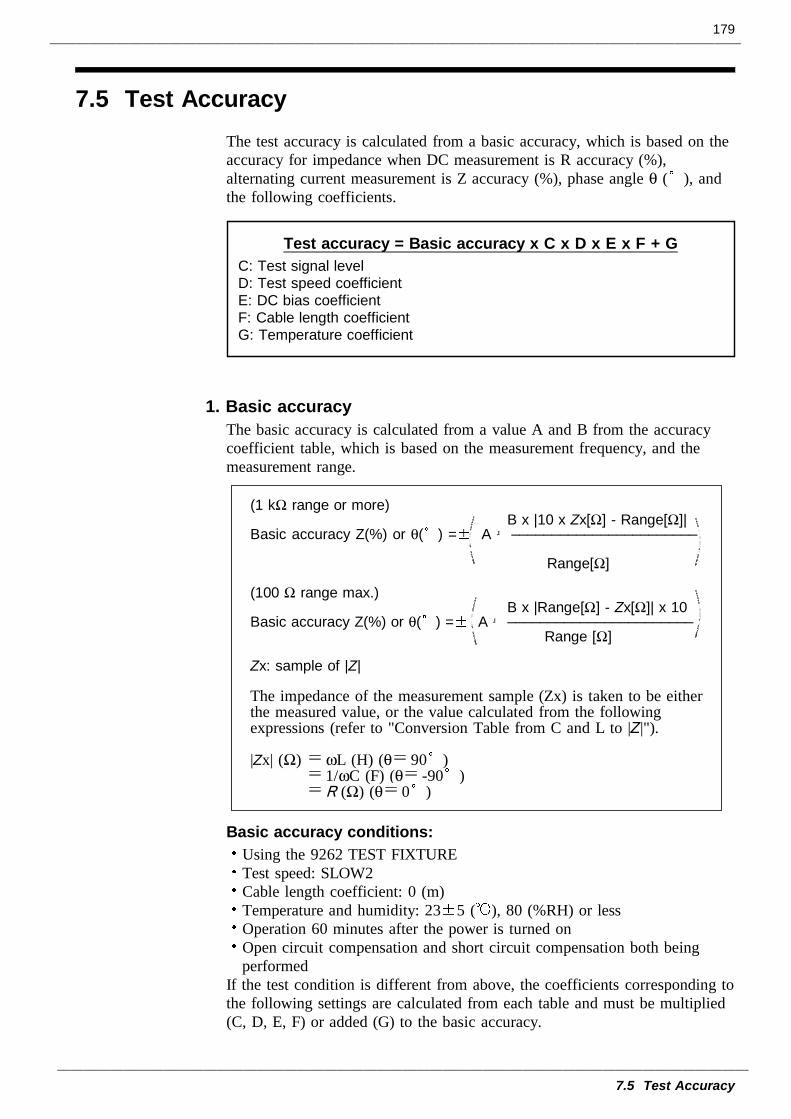
179
7.5 Test Accuracy
Test accuracy = Basic accuracy x C x D x E x F + GC: Test signal levelD: Test speed coefficientE: DC bias coefficientF: Cable length coefficientG: Temperature coefficient
(1 kΩ range or more) B x |10 x Zx[Ω] - Range[Ω]| Basic accuracy Z(%) or θ( ) = A +_______________________
Range[Ω]
(100 Ω range max.) B x |Range[Ω] - Zx[Ω]| x 10Basic accuracy Z(%) or θ( ) = A +_______________________ Range [Ω]
Zx: sample of |Z|
The impedance of the measurement sample (Zx) is taken to be eitherthe measured value, or the value calculated from the followingexpressions (refer to "Conversion Table from C and L to |Z|").
|Zx| (Ω) ωL (H) (θ 90 ) 1/ωC (F) (θ -90 ) R (Ω) (θ 0 )
7.5 Test AccuracyThe test accuracy is calculated from a basic accuracy, which is based on theaccuracy for impedance when DC measurement is R accuracy (%),alternating current measurement is Z accuracy (%), phase angle θ ( ), andthe following coefficients.
1. Basic accuracyThe basic accuracy is calculated from a value A and B from the accuracycoefficient table, which is based on the measurement frequency, and themeasurement range.
Basic accuracy conditions:Using the 9262 TEST FIXTURE Test speed: SLOW2Cable length coefficient: 0 (m)Temperature and humidity: 23 5 ( ), 80 (%RH) or lessOperation 60 minutes after the power is turned onOpen circuit compensation and short circuit compensation both beingperformed
If the test condition is different from above, the coefficients corresponding tothe following settings are calculated from each table and must be multiplied(C, D, E, F) or added (G) to the basic accuracy.
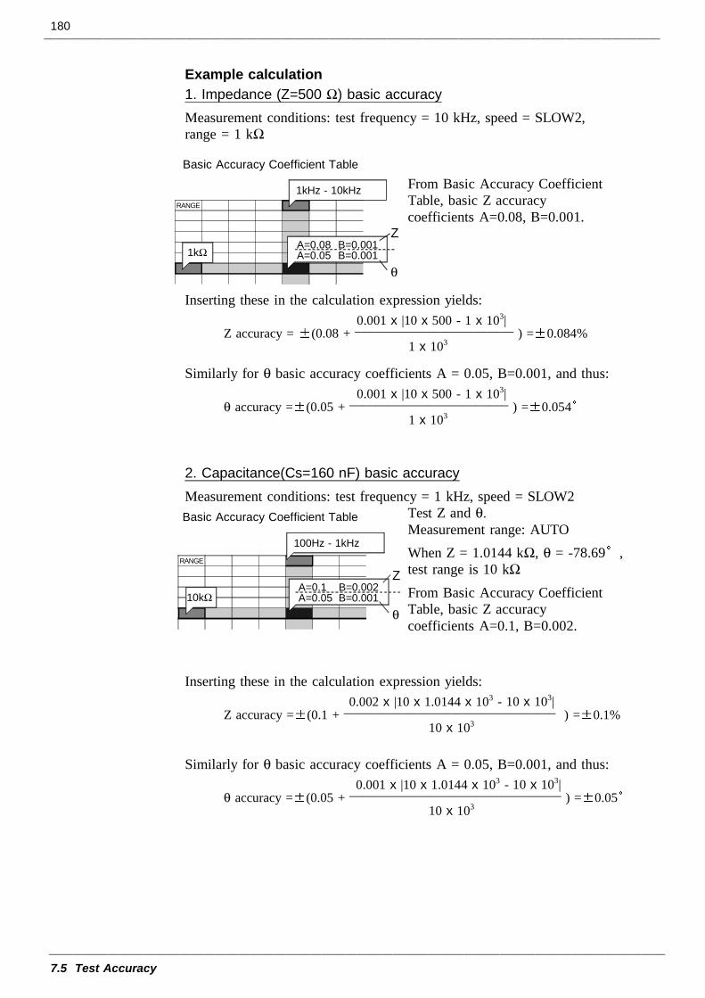
180
7.5 Test Accuracy
Z
θ
RANGE
Basic Accuracy Coefficient Table
A=0.08 B=0.001A=0.05 B=0.001
1kHz - 10kHz
1kΩ
0.001 x |10 x 500 - 1 x 10³|Z accuracy = (0.08 + ________________________ ) = 0.084% 1 x 10³
0.001 x |10 x 500 - 1 x 10³|θ accuracy = (0.05 + ________________________ ) = 0.054 1 x 10³
Z
θ
RANGE
Basic Accuracy Coefficient Table
A=0.1 B=0.002A=0.05 B=0.001
100Hz - 1kHz
10kΩ
0.002 x |10 x 1.0144 x 103 - 10 x 103|Z accuracy = (0.1 + ________________________________ ) = 0.1% 10 x 103
0.001 x |10 x 1.0144 x 103 - 10 x 103|θ accuracy = (0.05 + ________________________________ ) = 0.05 10 x 103
Example calculation1. Impedance (Z=500 Ω) basic accuracyMeasurement conditions: test frequency = 10 kHz, speed = SLOW2,range = 1 kΩ
From Basic Accuracy CoefficientTable, basic Z accuracycoefficients A=0.08, B=0.001.
Inserting these in the calculation expression yields:
Similarly for θ basic accuracy coefficients A = 0.05, B=0.001, and thus:
2. Capacitance(Cs=160 nF) basic accuracyMeasurement conditions: test frequency = 1 kHz, speed = SLOW2
Test Z and θ.Measurement range: AUTOWhen Z = 1.0144 kΩ, θ = -78.69 ,test range is 10 kΩ
From Basic Accuracy CoefficientTable, basic Z accuracycoefficients A=0.1, B=0.002.
Inserting these in the calculation expression yields:
Similarly for θ basic accuracy coefficients A = 0.05, B=0.001, and thus:
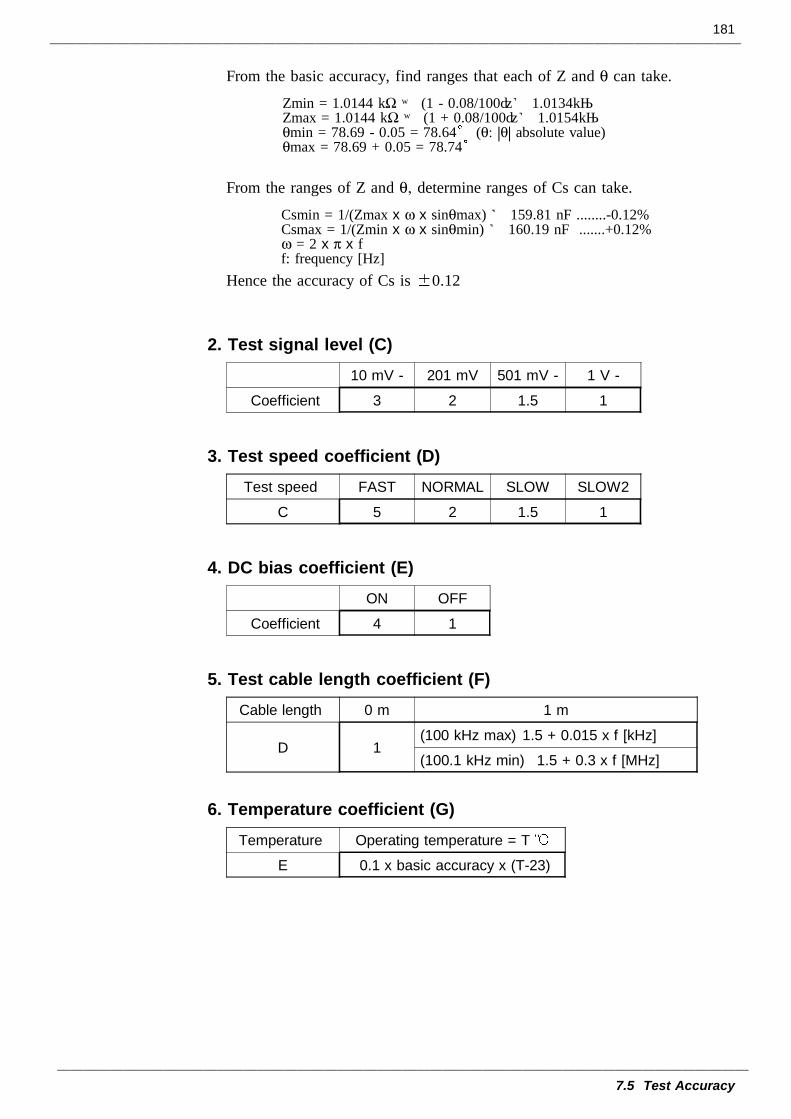
181
7.5 Test Accuracy
Zmin = 1.0144 kΩ × (1 - 0.08/100)≒ 1.0134kΩZmax = 1.0144 kΩ × (1 + 0.08/100)≒ 1.0154kΩθmin = 78.69 - 0.05 = 78.64 (θ: |θ| absolute value)θmax = 78.69 + 0.05 = 78.74
Csmin = 1/(Zmax x ω x sinθmax) ≒ 159.81 nF ........-0.12%Csmax = 1/(Zmin x ω x sinθmin) ≒ 160.19 nF .......+0.12%ω = 2 x π x ff: frequency [Hz]
10 mV - 201 mV 501 mV - 1 V -
Coefficient 3 2 1.5 1
Test speed FAST NORMAL SLOW SLOW2
C 5 2 1.5 1
ON OFF
Coefficient 4 1
Cable length 0 m 1 m
D 1(100 kHz max) 1.5 + 0.015 x f [kHz]
(100.1 kHz min) 1.5 + 0.3 x f [MHz]
Temperature Operating temperature = T
E 0.1 x basic accuracy x (T-23)
From the basic accuracy, find ranges that each of Z and θ can take.
From the ranges of Z and θ, determine ranges of Cs can take.
Hence the accuracy of Cs is 0.12
2. Test signal level (C)
3. Test speed coefficient (D)
4. DC bias coefficient (E)
5. Test cable length coefficient (F)
6. Temperature coefficient (G)
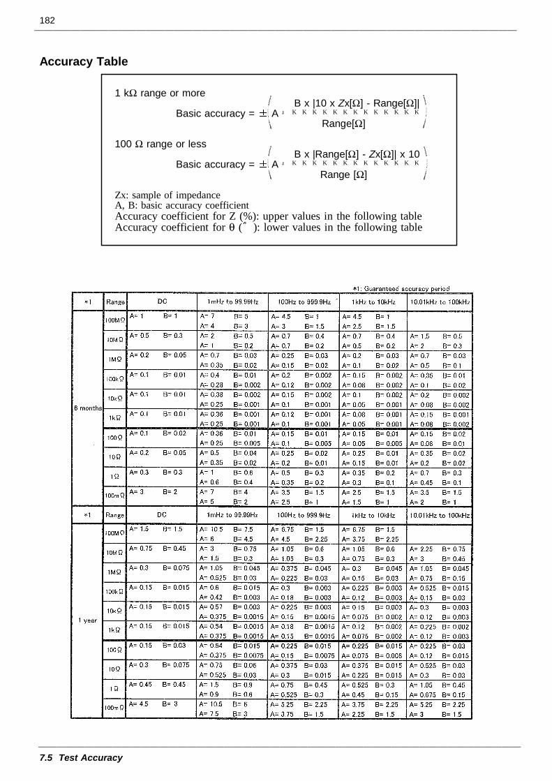
182
7.5 Test Accuracy
1 kΩ range or more B x |10 x Zx[Ω] - Range[Ω]|
Basic accuracy = A + Range[Ω]
100 Ω range or less B x |Range[Ω] - Zx[Ω]| x 10
Basic accuracy = A + Range [Ω]
Zx: sample of impedanceA, B: basic accuracy coefficientAccuracy coefficient for Z (%): upper values in the following tableAccuracy coefficient for θ ( ): lower values in the following table
Accuracy Table
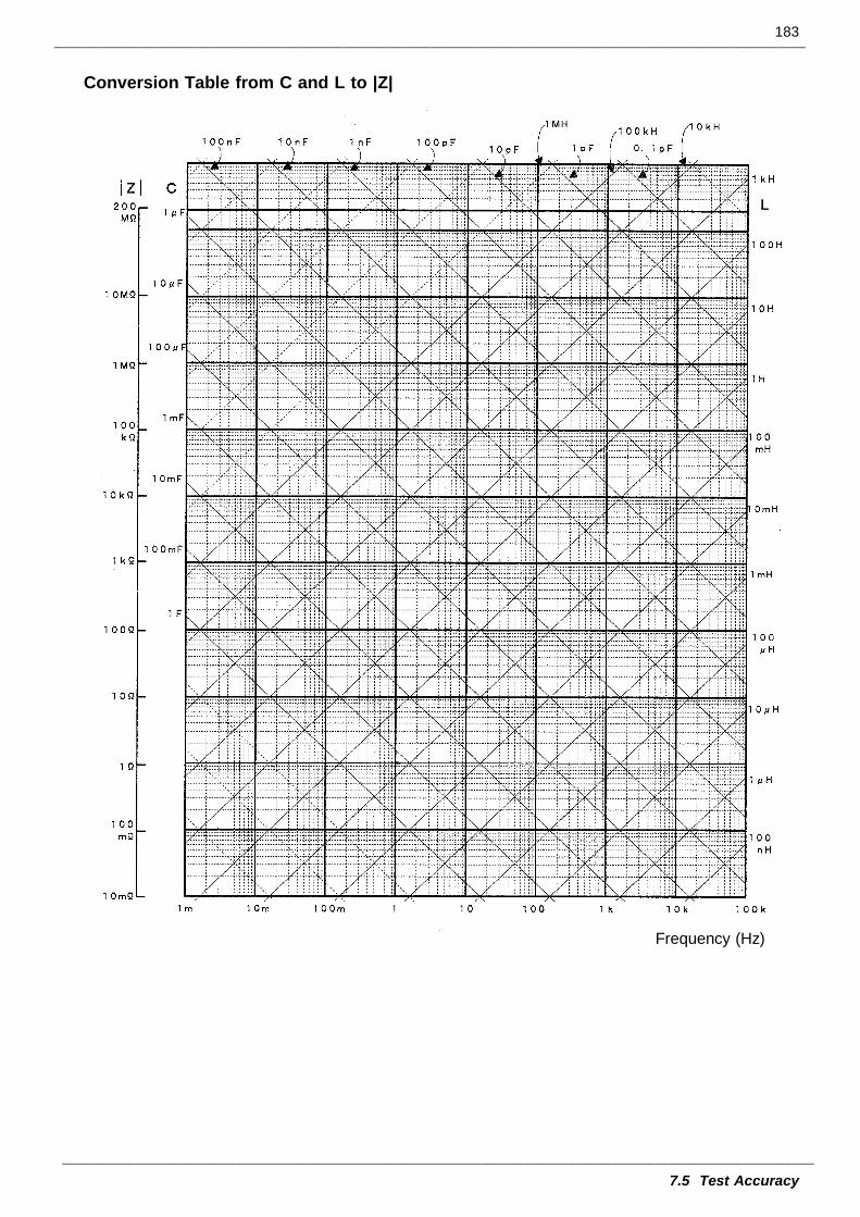
183
7.5 Test Accuracy
Conversion Table from C and L to |Z|
Frequency (Hz)

184
7.5 Test Accuracy
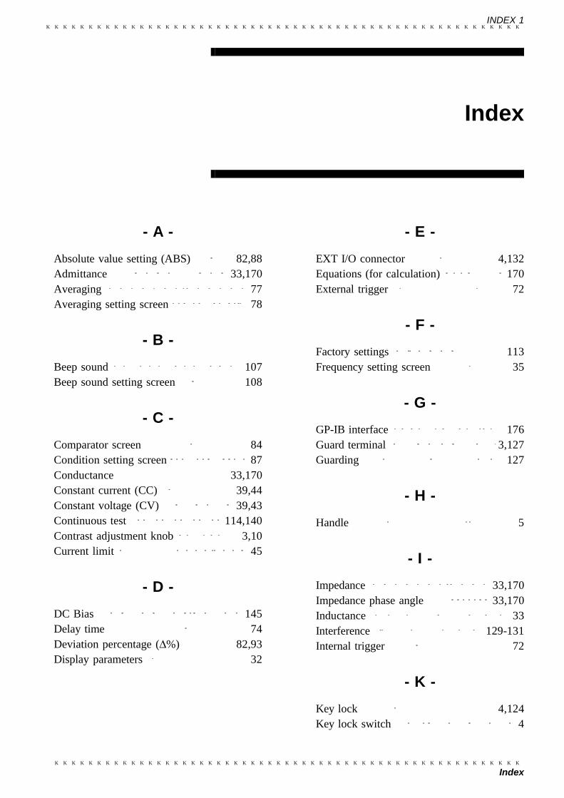
INDEX 1
Index
Index
- A -Absolute value setting (ABS) 82,88Admittance 33,170Averaging 77Averaging setting screen 78
- B -Beep sound 107Beep sound setting screen 108
- C -Comparator screen 84Condition setting screen 87Conductance 33,170Constant current (CC) 39,44Constant voltage (CV) 39,43Continuous test 114,140Contrast adjustment knob 3,10Current limit 45
- D -DC Bias 145Delay time 74Deviation percentage (∆%) 82,93Display parameters 32
- E -EXT I/O connector 4,132Equations (for calculation) 170External trigger 72
- F -Factory settings 113Frequency setting screen 35
- G -GP-IB interface 176Guard terminal 3,127Guarding 127
- H -Handle 5
- I -Impedance 33,170Impedance phase angle 33,170Inductance 33Interference 129-131Internal trigger 72
- K -Key lock 4,124Key lock switch 4
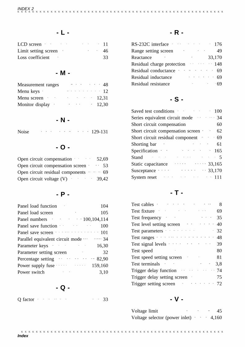
INDEX 2
Index
- L -LCD screen 11Limit setting screen 46Loss coefficient 33
- M -Measurement ranges 48Menu keys 12Menu screen 12,31Monitor display 12,30
- N -Noise 129-131
- O -Open circuit compensation 52,69Open circuit compensation screen 53Open circuit residual components 69Open circuit voltage (V) 39,42
- P -Panel load function 104Panel load screen 105Panel numbers 100,104,114Panel save function 100Panel save screen 101Parallel equivalent circuit mode 34Parameter keys 16,30Parameter setting screen 32Percentage setting 82,90Power supply fuse 159,160Power switch 3,10
- Q -Q factor 33
- R -RS-232C interface 176Range setting screen 49Reactance 33,170Residual charge protection 148Residual conductance 69Residual inductance 69Residual resistance 69
- S -Saved test conditions 100Series equivalent circuit mode 34Short circuit compensation 60Short circuit compensation screen 62Short circuit residual component 69Shorting bar 61Specification 165Stand 5Static capacitance 33,165Susceptance 33,170System reset 111
- T -Test cables 8Test fixture 69Test frequency 35Test level setting screen 40Test parameters 32Test ranges 48Test signal levels 39Test speed 80Test speed setting screen 81Test terminals 3,8Trigger delay function 74Trigger delay setting screen 75Trigger setting screen 72
- V -Voltage limit 45Voltage selector (power inlet) 4,160
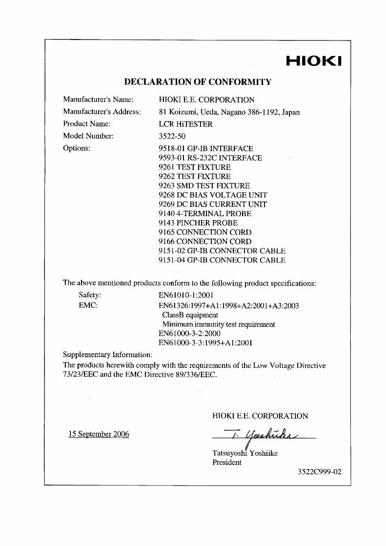

HIOKI 3522-50 LCR HiTESTERInstruction Manual
Publication date: September 2006 Revised edition 2
Edited and published by HIOKI E.E. CORPORATIONTechnical Support Section
All inquiries to International Sales and Marketing Department81 Koizumi, Ueda, Nagano, 386-1192, JapanTEL: +81-268-28-0562 / FAX: +81-268-28-0568E-mail: [email protected] http://www.hioki.co.jp/
Printed in Japan 3522C981-02
All reasonable care has been taken in the production of this manual, but if youfind any points which are unclear or in error, please contact your supplier orthe International Sales and Marketing Department at HIOKI headquarters.In the interests of product development, the contents of this manual are subjectto revision without prior notice.Unauthorized reproduction or copying of this manual is prohibited.

HEAD OFFICE81 Koizumi, Ueda, Nagano 386-1192, JapanTEL +81-268-28-0562 / FAX +81-268-28-0568E-mail: [email protected] / URL http://www.hioki.co.jp/HIOKI USA CORPORATION6 Corporate Drive, Cranbury, NJ 08512, USATEL +1-609-409-9109 / FAX +1-609-409-9108
3522C981-02 06-09H
Printed on recycled paper
2002-10改訂 枠消す
sharif_geraldizo
Tequipment