Installation, Operation, and Maintenance Manual for Protectowire ...
33
Installation, Operation & Maintenance Manual Protectowire Linear Heat Detector
Transcript of Installation, Operation, and Maintenance Manual for Protectowire ...
Installation, Operation& Maintenance Manual
ProtectowireLinear Heat Detector
Prot.Inst.Manual 3/29/11 9:50 AM Page 1

Protectowire Linear Heat Detector
Installation Hardware
TYPE EPC – VINYL JACKET
PHSC-155-EPC 155° (68°C)Max. Recommended Ambient Temp 115° F (46° C)
PHSC-190-EPC 190° (88°C)Max. Recommended Ambient Temp 150° F (66° C)
PHSC-220-EPC 220° (105°C)Max. Recommended Ambient Temp 175° F (79° C)
PHSC-280-EPC 280° (138°C)Max. Recommended Ambient Temp 200° F (93° C)
PHSC-356-EPC 356° (180°C)Max. Recommended Ambient Temp 221° F (105° C)
TYPE XCRFLUOROPOLYMER JACKET
PHSC-155-XCR 155° (68°C)Max. Recommended Ambient Temp 115°F (46°C)
PHSC-190-XCR 190° (88°C)Max. Recommended Ambient Temp 150°F (66°C)
PHSC-220-XCR 220° (105°C)Max. Recommended Ambient Temp 175°F (79°C)
PHSC-280-XCR 280° (138°C)Max. Recommended Ambient Temp 200°F (93°C)
PHSC-356-XCR 356° (180°C)Max. Recommended Ambient Temp 250°F (121°C)
TYPE PLR-RTHERMOPLASTIC ELASTOMER JACKET
PLR-155R 155° (68°C)Max. Recommended Ambient Temp 115° F (46° C)
PLR-190R 190° (88°C)Max. Recommended Ambient Temp 150° F (66° C)
TYPE XLT – PROPRIETARY POLYMER JACKET
PHSC-135-XLT 135° (57°C)Max. Recommended Ambient Temp 100° F (38° C)
PWSK-3Serviceable Splicing Connector
PFLFlexible Lead
PM-3Pipe Strap
BC-2Beam Clamp
WAW Clip
OHS-SSStainless Steel Line Clip
HPC-2Cable Tray ClipCC-2
Cable Tray Clip
PWSCSplicing Connector
Note: Colors shown are for illustrative purposes only. Actual jacket colors may vary.

ForwardAt the present time there is no code or recommended standards in the United States specificallycovering system design requirements for Linear Heat Detection Systems. In the past, informationpertinent to designing this type of system has been difficult to locate and generally based uponexisting requirements for spot heat detection devices.
In view of these factors, this manual has been designed to outline basic principles which shouldbe utilized in the design and layout of a Protectowire Linear Heat Detection System. These prin-ciples are based upon years of system design experience as well as nationally recognized coderequirements or approval agency standards. In addition, these principles recognize the operatingcharacteristics of the Protectowire detector and the environmental factors which may either aidor hinder its operation.
It is important to realize that codes, standards and other relevant material which may have beenused in preparing this manual, are dynamic documents which are subject to change over time.We have made a conscientious effort to ensure that all references in this manual which pertain tooutside approvals, regulatory requirements, codes or standards are current and as up-to-date aspossible. However, we recommend that in applications where a specific code requirement orinstallation standard is required, the Authority Having Jurisdiction (AHJ) be consulted to ensurecompliance. In all cases, local codes or installation requirements as stipulated or approved by theAHJ shall take priority.
Contents
Section Page
Introduction ..............................................................................................................................1
Product Description ..................................................................................................................1
How It Works ............................................................................................................................2
Electrical Arrangement ..............................................................................................................2
Maximum Copper Feed Cable Length (Table 1) ......................................................................3
General Principles......................................................................................................................4
Temperature Ratings ................................................................................................................5
Detector Location and Spacing ................................................................................................6
Protectowire Model Numbers and Maximum Listed Spacing ................................................6
Pre-Action Sprinkler Systems ....................................................................................................9
Environmental Considerations ..............................................................................................10
PWS Splicing Sleeves ..............................................................................................................10
Splicing Connectors ................................................................................................................11
Installation Detail ....................................................................................................................12
Fasteners ..................................................................................................................................12 General Purpose ..............................................................................................................12 Cable Trays ........................................................................................................................15 Pipe Mounting ..................................................................................................................15 Messenger Wire ................................................................................................................16
Installation Warnings ..............................................................................................................17
Special Application Installations ............................................................................................18 Cable Trays ........................................................................................................................18 Conveyors..........................................................................................................................19 Power Distribution Apparatus ..........................................................................................20 Dust Collectors/Baghouses ..............................................................................................21 Open Rack Storage ..........................................................................................................21 Floating Roof Tanks ..........................................................................................................21 Refrigerated Storage Areas................................................................................................22 Tunnels ..............................................................................................................................23 Self-Storage Warehouses ..................................................................................................23
Inspection and Testing ............................................................................................................24
Protectowire Test Equipment..................................................................................................25
Conversion Factors ..................................................................................................................25
Chemical Resistant Chart for Protectowire Jacket Materials EPC, XLT, CTI, PLR-R ..............26
Chemical Resistant Chart for Protectowire Jacket Material XCR, CTI-X................................27
©2015, The Protectowire Co., Inc, Pembroke, Massachusetts 02359

1
IntroductionSince The Protectowire Company introducedthe first Linear Type Heat Detector in the UnitedStates over 75 years ago, this type of detector,with its unique characteristics, has beenemployed in applications where it has provento be a highly reliable form of fire detection.
The construction and operating principles ofthe various linear heat detectors that are avail-able today, can with few exceptions, be classi-fied in the following major categories:
Analog (Integrating) Linear Type HeatDetectors - These detectors are composed of sensing ele-ments whose response to temperature issummed in some way along the length of theentire cable. The resistance of the insulationbetween the conductors is monitored by acontrol unit which may have adjustable alarmthreshold settings.
Typically, as the temperature of the cableincreases, the wire’s resistance will decrease.When the preset alarm threshold is reached analarm condition is signaled by the control unit.
Digital Linear Type Heat Detectors - Digital type detectors, such as Protectowire,consist of sensing elements which respond toa specific temperature at any point along theirlength. The inner conductors are coated witha polymer that melts at a predetermined tem-perature which allows the conductors tomake contact with one another and therebysignal an alarm condition.
While several other types of sensing technolo-gies, such as fiber optics and pressurizedpneumatic tubing are also in use, the twoproduct categories stated above are the mostwidely used today.
The present NFPA 72 National Fire Alarm andSignaling Code, provides basic information onthe application of linear heat detectors such aslocation and spacing distances for area protec-tion. The ability to correctly engineer the appli-cation of these detectors to special hazards,however, is provided mainly by the manufac-turers who have developed this technologyand expertise over the years.
In view of these factors, the purpose of thismanual is to ensure that coverage of the areato be protected is in accordance with acceptedfire protection principles and to provide uni-form installation guidance. Whenever there isa choice between two or more possible proce-dures, the one which results in increased pro-tection should be followed. Also discussed willbe the operating characteristics of theProtectowire sensor and the environmentalfactors which may influence its operation.
Product DescriptionProtectowire Linear Heat Detector is com-prised of two steel conductors individuallyencased in a heat sensitive polymer. Theencased conductors are twisted together toimpose a spring pressure between them, thenspirally wrapped with a protective tape andfinished with an outer jacket to suit the instal-lation environment.
The Detector’s current product range consistsof five distinct types of cable. Each designa-tion identifies a specific model type and outerjacket material which has unique characteris-tics that have been selected to accommodatethe widest range of installation environments.
EPC - Type EPC consists of a durable vinylouter jacket. This series is best described asmultipurpose and is well suited to a widerange of both commercial and industrial appli-cations. The outer jacket provides good all-around performance for most installations. Itfeatures low moisture absorption, resistance tomany common chemicals, excellent flexibilityat low temperatures and is flame retardant.
XCR - Type XCR utilizes a high performancefluoropolymer jacket. This detector is specifi-cally designed for use in applications whereextreme environmental and product perfor-mance criteria must be met. In general, theflame retardant, low smoke XCR jacket pro-vides excellent abrasion resistance andmechanical properties over a broad range oftemperatures. It provides excellent chemicaland permeation resistance to a wide variety ofacids, bases, and organic solvents as well as

2
simple gases. In addition, the jacket exhibitsvery little change in tensile properties uponoutdoor exposure to sunlight and weather.
XLT - Protectowire Type XLT is a uniquedetector that has been designed for use incold storage facilities and other applicationsthat require a low alarm activation tempera-ture. The outer jacket is a proprietary flameretardant polymer that provides low moistureabsorption, good chemical resistance andexcellent low temperature performance. Thisdetector has been UL and FM tested to –60°F(–51°C).
PLR-R – The Protectowire PLR models aremanufactured with special low resistance tri-metallic inner conductors that enable the useof longer detector zone lengths on most typesof fire alarm panels including addressable.The outer jacket consists of an extruded flameretardant thermoplastic elastomer with a spe-cial UV stabilizer added to enhance weather-ing performance. It is intended for a widerange of industrial and commercial applica-tions and is characterized by high resiliency,good fluid resistance, excellent weatheringproperties, and flexibility over a wide temper-ature range.
CTI – The Protectowire CTITM Series ofConfirmed Temperature Initiation LinearHeat Detectors are advanced multi-criteriadetectors that consist of two insulated specialmetallic alloy conductors that utilize the ther-mo-electric effect to measure the temperatureat the point of alarm. This technology is anenhancement to traditional digital linear heatdetection operation and provides for shortcircuit discrimination. Standard CTI modelsconsist of a durable flame retardant vinylouter jacket. This multipurpose jacket is suit-able for a wide range of commercial andindustrial applications and features low mois-ture absorption, resistance to many commonchemicals, and excellent low temperatureflexibility. CTI-X models utilize a high perfor-mance fluoropolymer jacket. This flame retar-dant, low smoke jacket provides excellentresistance to abrasion, chemicals, and out-door exposure to sunlight and weather.
How It WorksTraditional Protectowire is a fixed tempera-ture digital detector that is capable of initiat-ing an alarm at any point along its length,once the rated actuation temperature isreached. It is constructed of a twisted pair ofconductors coated with a thermoplastic coat-ing designed to soften at a specific tempera-ture. At the rated operating temperature, thedetector’s heat sensitive polymer insulationyields to the pressure upon it, permitting theconductors to contact each other creating ashort circuit. The short circuit is sensed bythe initiation device circuit which reports it asan alarm condition.The Protectowire Company has developedand patented a new enhanced digital linearheat detection technology known asConfirmed Temperature Initiation (CTI). Thistechnology is an enhancement to traditionaldigital linear heat detector operation. Wheretraditional digital linear heat detectors have asingle mode of detection, CTI digital linearheat detectors add a second mode of detec-tion. This second mode of detection utilizesthe thermo-electric effect to measure the tem-perature at the short circuited point of thedetector to confirm a true alarm conditionexists. This “Multi-Criteria” detection methodconfirms temperature before initiation andtherefore provides short circuit discrimina-tion. Since a mechanical short will not pro-duce a temperature above the alarm thresh-old, the possibility of mechanical damagecausing a false alarm is significantly reduced.
Electrical ArrangementSince Protectowire has been approved as aheat actuated automatic fire detector, it isintended to be used on a supervised initiatingcircuit of an approved fire protective signalingcontrol unit. The Detector must be installedin continuous runs without taps or branchesin accordance with applicable sections ofNFPA 70 National Electrical Code, NFPA 72National Fire Alarm and Signaling Code or asdetermined by the local authority having juris-diction. Within the context of this manual, theword “approved” is defined as that which is“acceptable to the authority having jurisdic-tion.” The authority having jurisdiction is

3
defined as “the organization, office or individ-ual responsible for approving equipment, aninstallation or a procedure.” [From NFPA 72]
Typically, an initiating device circuit will bedesignated as Class A or B depending uponthe circuits’ ability to continue to transmitalarm and trouble signals during single circuitfault conditions defined as follows:
• Circuits capable of transmitting an alarm sig-nal during a single open or ground fault,provided they do not occur simultaneously,are designed as Class A. In terms of an actualwiring configuration, this circuit typicallyconsists of a pair of wires running from thecontrol panel out through the hazard area,and returning in a continuous loop back tothe control panel where they are terminated.
• Circuits not capable of transmitting an alarmbeyond the location of the open or groundfault as specified above, are designatedClass B. Class B circuits generally do notreturn to the control panel, but are termi-nated by an end-of-line device remote fromthe control panel.
In addition to the class designationsdescribed above, initiating device circuits mayalso be designated by Style. The Style designa-tion is determined by the capability of the cir-cuit to transmit alarm and trouble signals dur-ing specified multiple circuit fault conditions,in addition to the single circuit fault condi-tions designated by the circuits’ class. For fur-ther details and a complete description of theperformance capabilities of various initiatingdevice circuits, please refer to NFPA 72.
Regardless of the Class or Style of the initiat-ing device circuits specified, the basic wiringpractices for the installation of Protectowirein each circuit remain the same. In general,the use of Protectowire in any initiating devicecircuit (zone), is limited to coverage of a spe-cific hazard or area requiring protection.
Copper feed wire, of an approved type, with aminimum conductor size of 18 AWG, shall beinstalled from the control panel out to thehazard area where it is then connected to thebeginning of the Protectowire portion of thecircuit. To determine the recommended wiregauge size and maximum length of copper
feed wire which may be used on each initiat-ing circuit of a Protectowire FireSystemControl Panel, refer to Table 1.
The Protectowire portion of every initiatingcircuit shall terminate at each end in anapproved zone box, end-of-line zone box, orother approved junction box provided as partof the system. Strain relief connectors, SeriesSR-502, shall be installed in all junction boxeswhere Protectowire enters or exits the enclo-sure, in order to hold the cable securely andmaintain dust and moisture tight conditions.All zone box enclosures shall be rated andapproved for use in the environment wherethey will be installed.
All electrical connections made within eachzone box between Protectowire and the cir-cuits’ interconnecting copper wire or end ofline device, shall be made via terminals. TheProtectowire Company supplies zone boxes,identified by the letters QC, which contain acompression type terminal strip which allowsthe installer to directly connect Protectowireconductors to the terminals. In all othercases, PFL Flexible Leads must be used to con-nect Protectowire conductors to electrical ter-minals. PFL’s consist of a twisted pair of insu-lated soft copper wires with a PWSC SplicingConnector attached on one end. The use ofwire nuts or other similar wiring devices notspecifically approved by The ProtectowireCompany, is not recommended and shall beconsidered a misapplication of the product.
Figures 1 and 1A depict the typical fieldwiring of a ZB-4-QC-MP Zone Box in a Class Bdetection circuit of a fire alarm system using
Maximum Copper Feed Cable Length vs. Wire Gauge (Diameter)
For Protectowire FireSystem Initiating CircuitsInitiating Circuits With or Without Alarm PointLocation Meter (Max. Resistance 100 ohms)
MAX. LENGTH OFF AWG* DIA. 2 CONDUCTOR CABLE
#18 1.02 mm 7,600 feet (2,316 m)#16 1.27 mm 12,200 feet (3,719 m)#14 1.63 mm 19,400 feet (5,913 m)#12 2.05 mm 30,800 feet (9,388 m)*American Wire Gauge
Table 1

4
Protectowire Linear Heat Detector. Figure 1Bdepicts the field wiring utilized in a Class Atype detection circuit. It is important to note
that in each case, Protectowire may be con-nected directly to the QC type terminals andthat all bends in the Detector should have aradius of not less than 2.5 inches (6.4 cm).
General PrinciplesProtectowire must be installed in continuousruns without taps or branches to comply with
locations and spacing prescribed by the approv-ing authorities. Except for zoning requirements(alarm source indication) the length of each runis limited, and controlled by the electrical char-acteristics of the control equipment to which theDetector is connected.
The Protectowire Company’s FireSystemControl Panels have been specifically designedfor compatible operation with ProtectowireLinear Heat Detector. Each FireSystem ControlPanel has been approved for operatingProtectowire Linear Heat Detector, approvedsmoke detectors or a combination of the twodevices on the same initiating circuit. The max-imum quantity of detectors and length of sen-sor cable will vary based upon the specificcontrol panel utilized. Please refer to theOperation and Maintenance Manual providedwith each system control panel for specificproduct information and limitations.
When Protectowire is utilized on other manu-facturer’s control panels, several importantfactors must be considered:
• Protectowire operates like a normally opencontact device which closes (shorts) uponactivation. Therefore, it must be utilizedonly on initiating circuits which can detectand annunciate a contact closure (short) asan alarm condition.
• Protectowire is a resistive contact device,
SR-502 SERIES
Figure 1
CONDUIT
FROM CONTROL
PANEL
CONDUIT TO
CONTROL PANEL
PROTECTOWIRE LHD
FIELD LOOP OUT
STRAIN RELIEF CONNECTOR
COPPER CONDUCTORS
WATERTIGHT - OILTIGHT
DETECTOR LINEAR HEAT PROTECTOWIRE
MOISTURE PROOF ENCLOSURE
PROTECTOWIRE LHD FIELD LOOP RETURN
OUT (+)
OUT (-)
RETURN (-)
RETURN (+)
SR-502 SERIES
Figure 1B
SR-502 SERIES
Figure 1A

5
unlike traditional spot heat detectors whichadd little appreciable resistance to a detec-tion circuit. The Detector’s comparativelyhigh resistance, make it necessary to evalu-ate each manufacturer’s control panel andlimit the Detector’s length to ensure thateach initiating circuit’s specified resistancelimitation is not exceeded. For most manu-facturer’s panels, the length of Protectowirethat can be used on each circuit may be rel-atively short since the typical detection cir-cuit is designed primarily to operate earlywarning smoke detectors.
• For applications in which long lengths ofProtectowire Linear Heat Detectors arerequired for use on other manufacturerscontrol panels, the Protectowire Companynow offers a series of detectors designatedwith the model prefix PLR. ProtectowirePLR models are manufactured with speciallow resistance (.058 ohms/ft. [.191ohms/m]) tri-metallic inner conductors thatenable the use of longer detector zonelengths on most types of fire alarm panels
including addressable.
Temperature RatingsThe Detector is made in different temperatureratings to allow for differences in normal or“ambient” temperature. These ratings andtheir approximate temperature of operationare as follows:
Regular 135°F (57°C)155°F (68°C)
Intermediate 190°F (88°C)220°F (105°C)
High 280°F (138°C)
Extra High 356°F (180°C)
Rules for selecting the proper rating to beinstalled in a given area are the same as forautomatic sprinklers and other heat actuateddevices. The factors which must be consideredare:
• What temperatures will the Detector be sub-jected to based upon the fire intensity char-acteristics of a particular fuel?
• What is the maximum ambient temperatureat the Detector?
Please refer to the Temperature Rating andModel Number Chart for a detailed listing ofeach Protectowire model and it’s maximuminstalled ambient temperature limit.
The selection of the Detector rating should bebased upon the most rapid response to theanticipated fire condition combined with theability to withstand a high, but not abnormalambient temperature, without causing anunwanted alarm. For example, Regular ratingshould not as a rule be put in an attic. In build-ings such as sheds and warehouses with roofsexposed to the sun and inadequately insulatedor ventilated, summer temperatures near theroof may be expected to rise well above 100°F(38°C) in many geographic areas. In anextremely hot climate, even Intermediate maybe too sensitive for a poorly ventilated attic areaor under an uninsulated metal roof.
In the same way, allowance must be made fornormally high temperatures in boiler andheater rooms, under glass exposures, in areaswhere steam pipes or heating ducts are run,near unit heaters and heating outlets, and inall other locations where ceiling temperaturesabove 100°F (38°C) are not indicative of fireor other abnormal conditions.
The area in front of and within the air flow ofheating outlets and unit heaters shouldalways be investigated. In freezer applica-tions, locations near refrigeration equipmentare also subject to surprisingly high tempera-tures during defrost cycles and require addi-tional caution in terms of detector placement.
Protectowire can sometimes be routedaround such “hot spots” within the spacinglimitations. When this is impractical, a sectionof higher rated Detector can be spliced intothe run. In uncertain situations, unwantedalarms will be avoided with little risk of delayin case of a real alarm, by using a Detector of
Protectowire Linear Heat Detector Resistance Table
PHSC Models .185 ohms/ft. .607 ohms/m.PLR Models .058 ohms/ft. .191 ohms/m.CTI Models .282 ohms/ft. .925 ohms/m.
All values shown are for a twisted pair and are considered typical.
6
the next higher rating throughout the areawhere the condition exists.
Detector Location &SpacingProtectowire Linear Heat Detector may beinstalled at the ceiling level to protect areaswithin buildings (area protection) in the samefashion as the more familiar spot type heatdetectors.
The majority of applications for linear detec-tors, however, involve installation of thedetector close to the hazard in order to pro-vide a rapid response. This is known as prox-imity or special application protection.Information on both types of installations willbe provided.
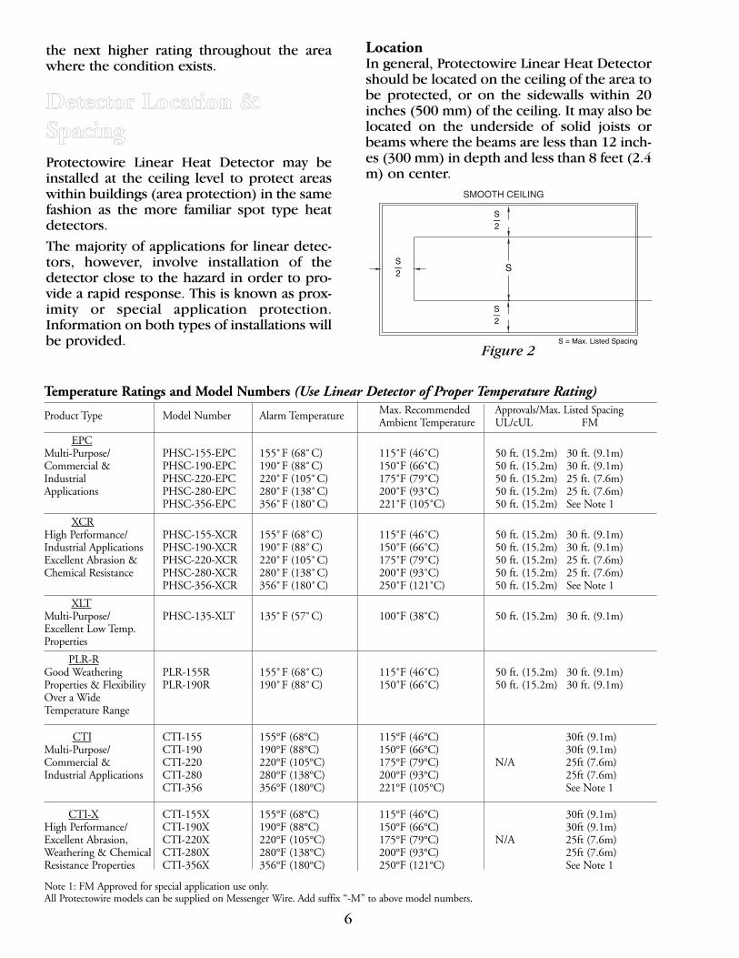
LocationIn general, Protectowire Linear Heat Detectorshould be located on the ceiling of the area tobe protected, or on the sidewalls within 20inches (500 mm) of the ceiling. It may also belocated on the underside of solid joists orbeams where the beams are less than 12 inch-es (300 mm) in depth and less than 8 feet (2.4m) on center.
Figure 2
S—2
S—2
S—2
S
S = Max. Listed Spacing
Temperature Ratings and Model Numbers (Use Linear Detector of Proper Temperature Rating)
Product Type Model Number Alarm Temperature Max. Recommended Approvals/Max. Listed Spacing Ambient Temperature UL/cUL FM
EPCMulti-Purpose/ PHSC-155-EPC 155˚F (68˚C) 115˚F (46˚C) 50 ft. (15.2m) 30 ft. (9.1m)Commercial & PHSC-190-EPC 190˚F (88˚C) 150˚F (66˚C) 50 ft. (15.2m) 30 ft. (9.1m)Industrial PHSC-220-EPC 220˚F (105˚C) 175˚F (79˚C) 50 ft. (15.2m) 25 ft. (7.6m)Applications PHSC-280-EPC 280˚F (138˚C) 200˚F (93˚C) 50 ft. (15.2m) 25 ft. (7.6m)
PHSC-356-EPC 356˚F (180˚C) 221˚F (105˚C) 50 ft. (15.2m) See Note 1
XCRHigh Performance/ PHSC-155-XCR 155˚F (68˚C) 115˚F (46˚C) 50 ft. (15.2m) 30 ft. (9.1m)Industrial Applications PHSC-190-XCR 190˚F (88˚C) 150˚F (66˚C) 50 ft. (15.2m) 30 ft. (9.1m)Excellent Abrasion & PHSC-220-XCR 220˚F (105˚C) 175˚F (79˚C) 50 ft. (15.2m) 25 ft. (7.6m)Chemical Resistance PHSC-280-XCR 280˚F (138˚C) 200˚F (93˚C) 50 ft. (15.2m) 25 ft. (7.6m)
PHSC-356-XCR 356˚F (180˚C) 250˚F (121˚C) 50 ft. (15.2m) See Note 1
XLTMulti-Purpose/ PHSC-135-XLT 135˚F (57˚C) 100˚F (38˚C) 50 ft. (15.2m) 30 ft. (9.1m)Excellent Low Temp.Properties
PLR-RGood Weathering PLR-155R 155˚F (68˚C) 115˚F (46˚C) 50 ft. (15.2m) 30 ft. (9.1m)Properties & Flexibility PLR-190R 190˚F (88˚C) 150˚F (66˚C) 50 ft. (15.2m) 30 ft. (9.1m)Over a Wide Temperature Range
CTI CTI-155 155°F (68°C) 115°F (46°C) 30ft (9.1m)Multi-Purpose/ CTI-190 190°F (88°C) 150°F (66°C) 30ft (9.1m)Commercial & CTI-220 220°F (105°C) 175°F (79°C) N/A 25ft (7.6m)Industrial Applications CTI-280 280°F (138°C) 200°F (93°C) 25ft (7.6m)
CTI-356 356°F (180°C) 221°F (105°C) See Note 1
CTI-X CTI-155X 155°F (68°C) 115°F (46°C) 30ft (9.1m)High Performance/ CTI-190X 190°F (88°C) 150°F (66°C) 30ft (9.1m)Excellent Abrasion, CTI-220X 220°F (105°C) 175°F (79°C) N/A 25ft (7.6m)Weathering & Chemical CTI-280X 280°F (138°C) 200°F (93°C) 25ft (7.6m)Resistance Properties CTI-356X 356°F (180°C) 250°F (121°C) See Note 1
Note 1: FM Approved for special application use only.All Protectowire models can be supplied on Messenger Wire. Add suffix “-M” to above model numbers.
7
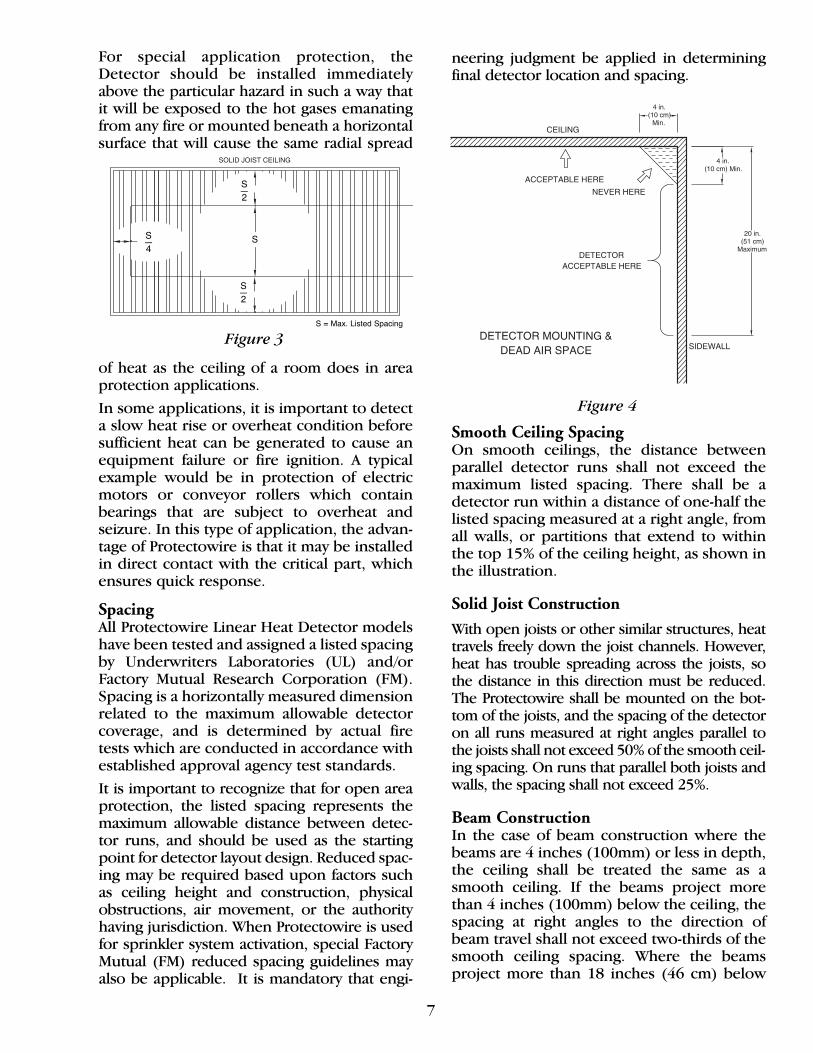
For special application protection, theDetector should be installed immediatelyabove the particular hazard in such a way thatit will be exposed to the hot gases emanatingfrom any fire or mounted beneath a horizontalsurface that will cause the same radial spread
of heat as the ceiling of a room does in areaprotection applications.
In some applications, it is important to detecta slow heat rise or overheat condition beforesufficient heat can be generated to cause anequipment failure or fire ignition. A typicalexample would be in protection of electricmotors or conveyor rollers which containbearings that are subject to overheat andseizure. In this type of application, the advan-tage of Protectowire is that it may be installedin direct contact with the critical part, whichensures quick response.
SpacingAll Protectowire Linear Heat Detector modelshave been tested and assigned a listed spacingby Underwriters Laboratories (UL) and/orFactory Mutual Research Corporation (FM).Spacing is a horizontally measured dimensionrelated to the maximum allowable detectorcoverage, and is determined by actual firetests which are conducted in accordance withestablished approval agency test standards.
It is important to recognize that for open areaprotection, the listed spacing represents themaximum allowable distance between detec-tor runs, and should be used as the startingpoint for detector layout design. Reduced spac-ing may be required based upon factors suchas ceiling height and construction, physicalobstructions, air movement, or the authorityhaving jurisdiction. When Protectowire is usedfor sprinkler system activation, special FactoryMutual (FM) reduced spacing guidelines mayalso be applicable. It is mandatory that engi-
neering judgment be applied in determiningfinal detector location and spacing.
Smooth Ceiling SpacingOn smooth ceilings, the distance betweenparallel detector runs shall not exceed themaximum listed spacing. There shall be adetector run within a distance of one-half thelisted spacing measured at a right angle, fromall walls, or partitions that extend to withinthe top 15% of the ceiling height, as shown inthe illustration.
Solid Joist Construction
With open joists or other similar structures, heattravels freely down the joist channels. However,heat has trouble spreading across the joists, sothe distance in this direction must be reduced.The Protectowire shall be mounted on the bot-tom of the joists, and the spacing of the detectoron all runs measured at right angles parallel tothe joists shall not exceed 50% of the smooth ceil-ing spacing. On runs that parallel both joists andwalls, the spacing shall not exceed 25%.
Beam ConstructionIn the case of beam construction where thebeams are 4 inches (100mm) or less in depth,the ceiling shall be treated the same as asmooth ceiling. If the beams project morethan 4 inches (100mm) below the ceiling, thespacing at right angles to the direction ofbeam travel shall not exceed two-thirds of thesmooth ceiling spacing. Where the beams project more than 18 inches (46 cm) below
Figure 3
Figure 4
S—4
S—2
S—2
S = Max. Listed Spacing
S
8
the ceiling and are spaced more than 8 feet(2.4 m) on center, each bay formed by thebeams shall be treated as a separate arearequiring detector coverage.
Detector Mounting & Dead Air SpaceHeat from a fire rises to the ceiling in a plumeand spreads radially from the fire source. Asthe hot gases cool, they begin to bank downfrom the ceiling. The corner where the ceilingand wall meet forms an area known as “deadair space” as shown in Figure 4. In most fires,this dead air space is the triangular areaformed along the ceiling by measuring 4 inch-es (10 cm) out from the corner, and 4 inches(10 cm) down the side wall. Protectowireshould not be placed in this area.
High Ceiling ConsiderationsThe purpose of this section is to discuss theeffects of ceiling height on the installed spacingof Protectowire Linear Heat Detector and toexplain the importance of modifying the listedspacing in order to achieve detector response.
Logic tells us that a detector will ordinarilyoperate sooner in detecting a fire if it is closerto the fire source. This is because as smokeand heat rise from a fire, they do so in aplume which has the general shape of aninverted cone. The concentration of smokeand heat within the cone varies inversely as avariable function of the distance from thesource. This characteristic is amplified duringthe early stages of a fire because the angle ofthe plume is wide. As the fire grows in size,the angle of the plume narrows, which tendsto reduce the effect of ceiling height.
As the ceiling height increases, a larger-size fireis necessary to actuate the same detector in thesame length of time. As a result of this, systemdesign practice mandates that the listed spacingof heat detectors be reduced for the purposesof providing faster detector response to a fire,and to increase the likelihood that the detectorwill respond to a smaller fire.
To compensate for the effect that high ceilinginstallations have on detector performance,The National Fire Alarm and Signaling Code,NFPA 72, provides derating factors that can beapplied to the listed spacing of any heat detec-tor when installed on ceilings 10 to 30 feet (3mto 9.1m) high. These derating factors areshown as a percentage of the detector’s listedspacing, and have been developed to provide
detector performance on higher ceilings [to 30feet (9.1m)] that is equivalent to that of detec-tors installed on a 10 foot (3m) ceiling. Thismethod provides an accepted, easy to applyapproach, in dealing with high ceiling applica-tions for generalized fire conditions. It doesnot, however, provide guidance for ceilingheights over 30 feet (9.1m). In such installa-tions, engineering judgment, the manufactur-er’s recommendation or detector spacingapproved by the authority having jurisdictionshould be used.
In many applications, Protectowire LinearHeat Detector is used for electrical activationof pre-action or deluge type sprinkler sys-tems. In sprinkler release applications, specialFactory Mutual (FM) spacing requirementsmay be required. In some cases, FM spacingrequirements may conflict with the recom-mendations for high ceilings provided inNFPA 72. In these situations, general practiceis to utilize NFPA 72 recommendations in sys-tems involving detection only, and to followFM detector spacing guidelines when design-ing a detection system to be used for sprinklersystem release. In all cases, the final detectorspacing must be accepted and approved bythe authority having jurisdiction.
S 2 S S S
2
S 2
S 2
S 2
S 2
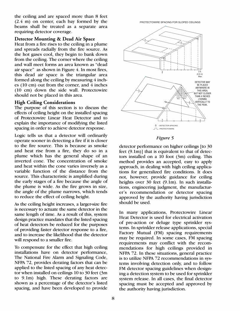
Figure 5
DETECTOR MAYBE PLACED
ANYWHERE INTHIS AREA,
BUT NOT CLOSERTHAN 4 INCHES
(102MM) VERTICALLY TO
THE PEAK.

9
The reduction of heat detector spacing onhigh ceilings as required in NFPA 72, is by nomeans universally applied. Several types ofheat detectors including “line-type electricalconductivity detectors,” more commonlyknown as analog line-type detectors, havebeen identified in NFPA 72 as an “exception”to the high ceiling derating requirements.This “exception” has been promoted on sev-eral levels to infer that analog detectors havebeen excluded from the reduced spacingrequirements due to superior performance.
In actual fact, The Fire Detection Institute FireTest Report, which was used as a basis for thehigh ceiling derating information containedin NFPA 72, does not include data on integra-tion-type detectors and therefore, “excep-tion” was granted only until such time as datais developed for this type of detector.
For the purposes of this manual, good systemdesign dictates that the listed spacing of allinstalled heat detectors, regardless of operat-ing principle, be reduced to compensate forthe effects of ceiling height.
Sloped CeilingsIn areas having a sloped or peaked ceiling, atleast one line of Protectowire must be locatedat or within 3 feet (0.9 m) measured horizon-tally from the peak, but not closer than 4 inches(10 cm) vertically to the peak. The spacing ofadditional runs of Protectowire, if any, shouldbe based on the horizontal distance projecteddown from the ceiling and in accordance withthe type of ceiling construction.
Pre-Action Sprinkler SystemsWhen Protectowire Linear Heat Detector isused as the initiating device for pre-actionsprinkler systems, special Factory Mutual loca-tion and spacing guidelines may be found inFM Loss Prevention Data Sheets such as 8-29,which covers Refrigerated Storage Facilities.
As a general rule, FM acceptance criteria for openarea ceiling applications such as that covered in 8-29, requires that the detector beinstalled at a spacing not exceeding the allowable
ceiling sprinkler spacing. The detector spacing is accomplished by maintaining a con-tinuous run of Protectowire parallel to eachbranch line. At the end of each branch line thedetector is run at a right angle (maintainingthe appropriate 2.5 inch [6.4 cm] bendradius) across to the next adjacent branch lineand proceeds in the opposite direction. Thedetector run continues in this manner until the end of the detection zone isreached, or until the maximum Protectowirecontrol panel zone allocation is reached, typi-cally 5,000 feet [1,524 m], or 10,000 feet[3,048 m] depending on the model.
The completed Protectowire portion ofthe circuit for each overhead zone will bein a serpentine pattern as illustrated in
Figure 6, with the Protectowire terminated ateach end in an approved zone box, end-of-line zone box, or other approved junctionbox provided as part of the system. Strainrelief connectors, Series SR-502, shall beinstalled in all junction boxes whereProtectowire enters or exits the enclosure, inorder to hold the cable securely and maintaindust and moisture tight conditions. (SeeFigures 1, 1A, 1B).
Detector Zoning For Sprinkler ReleaseDetection system zone allocation should notbe confused with zone allocation for sprinklersystems. A water system, or sprinkler zonecontrolled by one valve may have a differentmeaning than terminology used for detectionzones. Generally, a detection zone refers to adefined area within a protected premise. Inthe case of Protectowire, it also refers to themaximum amount of linear heat detectioncable that a panel will operate on a singledetection circuit (zone). Protectowire panelssuch as the FS2000 and 2600 HD Series are
,
Figure 6
10
approved for 5,000 feet (1,524 m) per zone.The SRP-4x4 is approved for up to 10,000 feet[3,048 m] per zone.
On the other hand, a water zone, or system,has an area of coverage based upon itsdesigned discharge density which may exceedthe area which can be covered effectively by asingle detection zone. When a detection zone’slength limitation is exceeded, a second detec-tion zone is required to complete the total areaof detector coverage needed to match the areaof coverage provided by the correspondingwater zone. In this scenario, the two detectionzones are connected at the control panel in an“or” configuration so that the actuation ofeither detection zone will operate the solenoid of the corresponding water system. Do not extend a detection circuit fromone area into an area serviced by anotherwater valve. Each water valve must be con-trolled by one or more detection zones physi-cally located in the same area.
Rack systems -With the variety of rack systems inuse today, a wide range of configurations maybe confronted when installing linear heat detec-tion systems for electrical actuation of sprinklervalves. As a minimum, the guidelines of FactoryMutual in conjunction with the manufacturer’srecommendation must be followed. In general,rack detection systems should be installed based upon the following criteria:
For single row and double row racks, oneline of detection cable is needed at each in-rack sprinkler level. Locate the linear heatdetector cable in the transverse or longitu-dinal flue space and attach it to a horizon-tal load beam at the sprinkler line level.
For multiple-row racks, a line of detectioncable is needed for each in-rack sprinklerline at each in-rack sprinkler level. Locatethe linear heat detection cable in either thetransverse or longitudinal flue space andattach it to a horizontal load beam at thesprinkler branch line levels.
EnvironmentalConsiderationsProtectowire is available in a range of con-structions and jacket materials, in order to
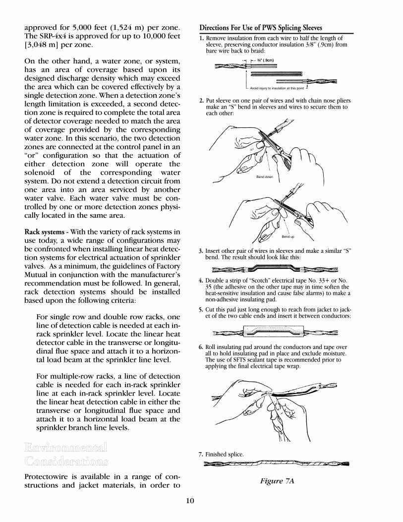
Directions For Use of PWS Splicing Sleeves1. Remove insulation from each wire to half the length of
sleeve, preserving conductor insulation 3/8” (.9cm) frombare wire back to braid:
2. Put sleeve on one pair of wires and with chain nose pliersmake an “S” bend in sleeves and wires to secure them toeach other:
3. Insert other pair of wires in sleeves and make a similar “S”bend. The result should look like this:
7. Finished splice.
6. Roll insulating pad around the conductors and tape overall to hold insulating pad in place and exclude moisture.The use of SFTS sealant tape is recommended prior toapplying the final electrical tape wrap.
5. Cut this pad just long enough to reach from jacket to jack-et of the two cable ends and insert it between conductors:
4. Double a strip of “Scotch” electrical tape No. 33+ or No.35 (the adhesive on the other tape may in time soften theheat-sensitive insulation and cause false alarms) to make anon-adhesive insulating pad.
Figure 7A
Avoid injury to insulation at this point
Bend down
Bend up

11
Directions For Use of PWSC Splicing Connectors
2. Install wires as shown below making sure the entire 1/2”(1.3cm) portion of bare Protectowire Linear Heat Detectorconductor is embedded in splicing connector.
4. Using 4”-5” (10.1cm-12.7cm) of SFTS tape, starts at least 2”(5.1cm) before connector and wrap the splice. Stretch andoverlap each wrap of tape by 1/4-1/2 the width. SFTS tapeis recommended specifically for outdoor or high humidityinstallations.
5. Finish the splice seal by wrapping “Scotch/3M” brand “Super33+” or “No. 35” electrical tape over the SFTS sealant.
3. Secure Protectowire Linear Heat Detector by tighteningthe connector screws. Plastic screw turrets may betrimmed with snips or utility knife for easier taping.
1. Remove insulation from each wire leaving 1/2” (1.3cm) ofbare Protectowire Linear Heat Detector conductor, preserv-ing 3/8” (.9cm) of insulation from bare wire back to the cov-ering.
Flexible Leads
Flexible leads are furnished with most Protectowire systemsfor connecting Protectowire Linear Heat Detector to terminals.Attach these to the Detector ends, insulate and tape like asplice.
Figure 7B
provide resistance to attack from variouschemicals, liquids, and environmental factors.
To assist the System Designer in selecting theproper Protectowire model for the installa-tion environment, a Chemical ResistanceChart for the jacket materials used in allProtectowire Linear Heat Detector models isshown on page 26 of this manual. This chartlists the effects of many common chemicals,and is useful in determining the suitability ofinstalling Protectowire in various types ofaggressive environments.
Because it is not always possible to accuratelypredict what effect extremely aggressive envi-ronmental factors may have on a Detector’suseful service life, we recommend that whenpossible, actual field installation tests be per-formed on product samples to determinewhether or not the model selected may be suit-able for use in the proposed environment.
In outdoor applications, the effects of solarradiation must also be considered during thedesign of the system. Exposure to direct sun-light or so called “black body” radiation maycause the temperature of the detector or itsmounting surface to exceed the maximumambient limit or the alarm actuation tempera-ture of the sensor.
It is important, therefore, to take precaution-ary steps, such as installing a protective shieldover the sensing cable to reduce the installedlocation temperature to acceptable limits.Shielding also reduces the long term degrada-tion of the outer jacket from influences suchas ultraviolet radiation. Protectowire modelsXCR and PLR-R have special inhibitors in thejacket material to help reduce the effects ofUV radiation and extend the detector’s usefulservice life.
For outdoor applications, the recommendedmethod of splicing and terminating theProtectowire requires that all connections bemade within appropriately rated junctionboxes. All other applications, particularlywhere high humidity or dampness may bepresent, require the use of PWSK-3Protectowire Field Serviceable Connectors orthe use of SFTS Sealant Tape for all in-linesplices made with PWSC or PWS splicingdevices. Refer to Figures 7A, 7B and 7C forthe correct splicing procedures.Figure 7C
PROTECTOWIRE FIELD SERVICEABLE CONNECTORModel Number: PWSK-3
Avoid injuryto insulationat this point
Splicingconnector
3/8" (.9cm)
2" 2"
1/2"(1.3cm)
12
Installation Detail Installation efficiency will be gained by care-fully planning the routing of each Protecto-wire run. This will ordinarily be done on thebasis of a scale drawing of the area to be pro-tected, consideration of the location and spac-ing information presented in the DetectorLocation and Spacing Section of this manual,and other less obvious factors which may beobserved at the site.
Protectowire is designed to respond rapidly tochanges in temperature caused by a fire.Therefore, its mounting hardware must pro-vide adequate support at temperatures whichare at least as high as the alarm trip point.Fasteners should typically be spaced every 5-10 feet (1.5-3m), or as may be necessary toprevent the wire from excessive sagging whichputs undue stress on the wire at the fasteningpoints. Improper installation and fasteningmay also subject the Detector to physical dam-age in some process areas or interactive appli-cations, such as rack storage facilities.
FastenersProtectowire approved fasteners are generallydesigned to lightly clamp the detector whichenables a tension to be applied progressively.This method is better than arrangements whichapply a high tensile load at the end of each runor clamp and compress the sensor cable sotightly that the inner insulation becomes dam-aged. To ensure a trouble-free installation, only
Protectowire supplied or approved fastenersshould be used. The use of non-approved fasten-ers may physically damage the Detector therebycausing “false alarms” and in some cases voidthe Detector’s warranty.
Several categories of approved fasteningdevices are available to hold the detector inplace without injuring it. These include:
• General Purpose - These fastening devices arecommonly used in area detection applica-tions where the Detector will be installed onthe ceiling, roof or side walls.• Cable Tray Applications - These versatile fas-teners are intended to mount the Detector toa variety of cable tray configurations, but mayalso be used for many other mounting situa-tions such as conveyors, angle irons, I- beams,bar joists, etc.• Pipe Mounting - A category of fastenerswhich allow the Detector to be mounteddirectly to associated sprinkler pipes in vari-ous pre-action and deluge systems.• Messenger Wire - When installing Protectowirewith optional stainless steel messenger (sup-port) wire, eyebolts and turnbuckles arerequired. Ideal for spanning large open areas orwhere mounting support structures are limited.
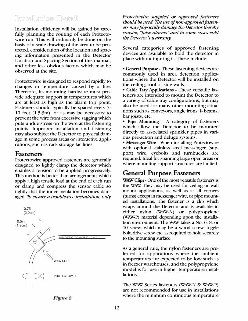
General Purpose FastenersWAW Clips -One of the most versatile fasteners isthe WAW. They may be used for ceiling or wallmount applications, as well as at all corners(turns) except in messenger wire, or pipe mount-ed installations. The fastener is a clip whichwraps around the Detector and is available ineither nylon (WAW-N) or polypropylene (WAW-P) material depending upon the installa-tion environment. The WAW takes a No. 6, 8, or10 screw, which may be a wood screw, togglebolt, drive screw, etc. as required to hold securelyto the mounting surface.
As a general rule, the nylon fasteners are pre-ferred for applications where the ambienttemperatures are expected to be low such asin freezer warehouses, and the polypropylenemodel is for use in higher temperature instal-lations.
The WAW Series fasteners (WAW-N & WAW-P)are not recommended for use in installationswhere the minimum continuous temperatureFigure 8
13
is less than -40°F (-40°C) or the maximumcontinuous use temperature will exceed190°F (88°C).
When installed at the corners (turns) of ceil-ing mounted installations, the WAW mountingscrew should be set in 1/2 to 3/4 inch (1.3-2.0cm) from the intersection of the lines(Figure 8) to provide a free bend in theDetector, and should not be fully tighteneduntil fastening between corners has beencompleted. Installation is simplified and thebest appearance assured by pulling theDetector into line from corner to corner andapplying the required intermediate fastenerswhile a light tension is held upon it.
OHS Line ClipsThe OHS clip is available in several differentconfigurations and is used mainly as an inter-mediate fastener between corner mountedWAW clips, which provide the main support.
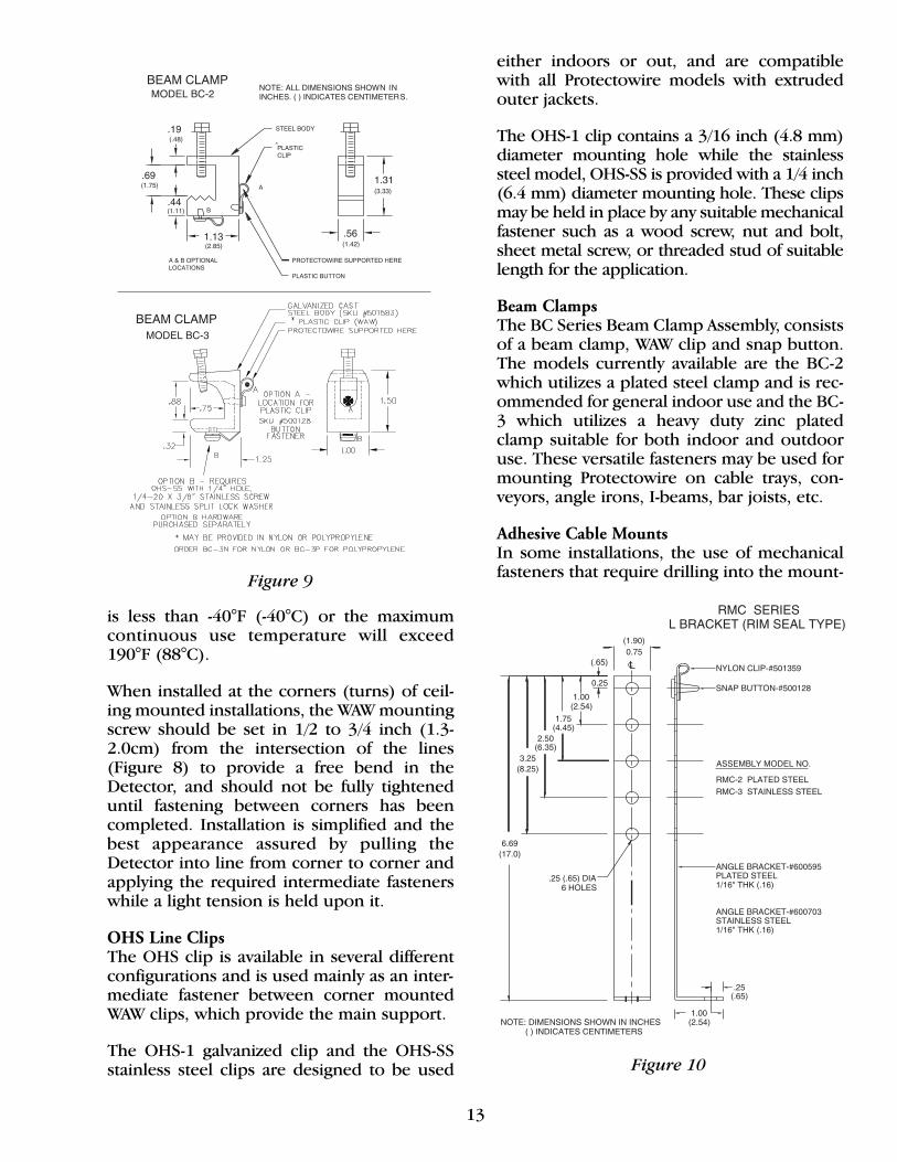
The OHS-1 galvanized clip and the OHS-SSstainless steel clips are designed to be used
either indoors or out, and are compatiblewith all Protectowire models with extrudedouter jackets.
The OHS-1 clip contains a 3/16 inch (4.8 mm)diameter mounting hole while the stainlesssteel model, OHS-SS is provided with a 1/4 inch(6.4 mm) diameter mounting hole. These clipsmay be held in place by any suitable mechanicalfastener such as a wood screw, nut and bolt,sheet metal screw, or threaded stud of suitablelength for the application.
Beam ClampsThe BC Series Beam Clamp Assembly, consistsof a beam clamp, WAW clip and snap button.The models currently available are the BC-2which utilizes a plated steel clamp and is rec-ommended for general indoor use and the BC-3 which utilizes a heavy duty zinc platedclamp suitable for both indoor and outdooruse. These versatile fasteners may be used formounting Protectowire on cable trays, con-veyors, angle irons, I-beams, bar joists, etc.
Adhesive Cable MountsIn some installations, the use of mechanicalfasteners that require drilling into the mount-
Figure 10
Figure 9
ing surface is prohibited, or simply not possi-ble. An example of this type of application isthe mounting of Protectowire directly ontolarge power transformers. For many of thesesituations, the only viable solution is to utilizean adhesive mounting system consisting ofEMS Cable Mounts, PLT Cable Ties and anapproved industrial adhesive. The EMS CableMounts and PLT Cable Ties are constructed ofblack weather resistant nylon, and when usedwith the approved adhesive, are suitable foroutdoor use.
As a cautionary note, the use of adhesivemounting should be limited to applica-tions which will not be subjected to tem-perature extremes or harsh chemical envi-ronments that could effect the service lifeof the adhesive and cause it to fail prema-turely. Installation environments whichcontain solvents, strong acids or alkalisshould always be avoided. In addition,the adhesive mounting system shall notbe used where the continuous operatingtemperature will be less than 0°F (-18°C)or exceed 180°F (82°C).
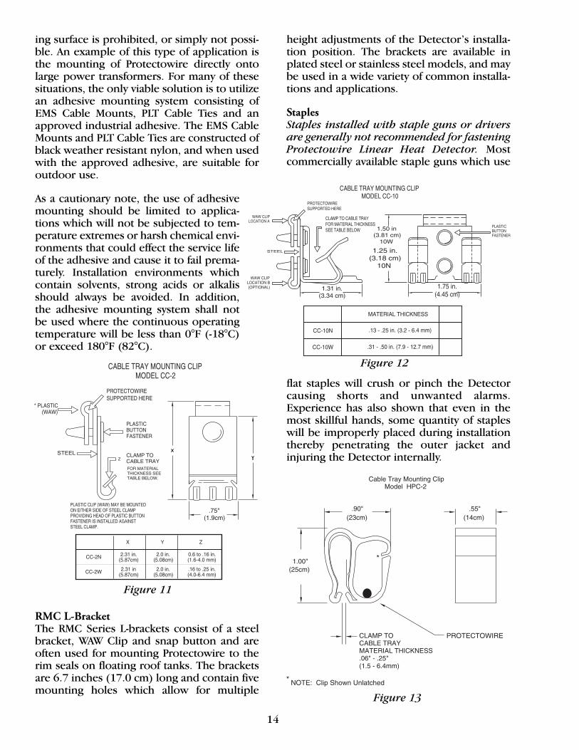
RMC L-Bracket The RMC Series L-brackets consist of a steelbracket, WAW Clip and snap button and areoften used for mounting Protectowire to therim seals on floating roof tanks. The bracketsare 6.7 inches (17.0 cm) long and contain fivemounting holes which allow for multiple
14
height adjustments of the Detector’s installa-tion position. The brackets are available inplated steel or stainless steel models, and maybe used in a wide variety of common installa-tions and applications.
StaplesStaples installed with staple guns or driversare generally not recommended for fasteningProtectowire Linear Heat Detector. Mostcommercially available staple guns which use
flat staples will crush or pinch the Detectorcausing shorts and unwanted alarms.Experience has also shown that even in themost skillful hands, some quantity of stapleswill be improperly placed during installationthereby penetrating the outer jacket andinjuring the Detector internally.
Figure 11
Figure 12
Figure 13
15
In rare situations where the use of staples isconsidered to be the only appropriate meansof fastening, an Arrow Model T-25M StapleGun or equivalent must be used. This type ofdriver utilizes a crown head staple and isdesigned to minimize the risk that the staplewill be driven into the Detector hard enoughto crush or pinch it. The risk of damaging thewire may be further reduced by selecting a staple of proper length based upon the hard-ness of the mounting material.
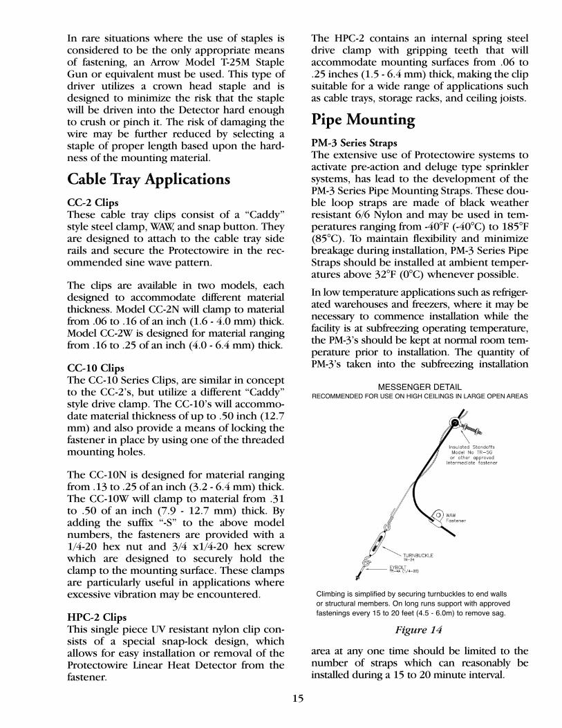
Cable Tray ApplicationsCC-2 ClipsThese cable tray clips consist of a “Caddy”style steel clamp, WAW, and snap button. Theyare designed to attach to the cable tray siderails and secure the Protectowire in the rec-ommended sine wave pattern.
The clips are available in two models, eachdesigned to accommodate different materialthickness. Model CC-2N will clamp to materialfrom .06 to .16 of an inch (1.6 - 4.0 mm) thick.Model CC-2W is designed for material rangingfrom .16 to .25 of an inch (4.0 - 6.4 mm) thick.
CC-10 ClipsThe CC-10 Series Clips, are similar in conceptto the CC-2’s, but utilize a different “Caddy”style drive clamp. The CC-10’s will accommo-date material thickness of up to .50 inch (12.7mm) and also provide a means of locking thefastener in place by using one of the threadedmounting holes.
The CC-10N is designed for material rangingfrom .13 to .25 of an inch (3.2 - 6.4 mm) thick.The CC-10W will clamp to material from .31to .50 of an inch (7.9 - 12.7 mm) thick. Byadding the suffix “-S” to the above modelnumbers, the fasteners are provided with a1/4-20 hex nut and 3/4 x1/4-20 hex screwwhich are designed to securely hold theclamp to the mounting surface. These clampsare particularly useful in applications whereexcessive vibration may be encountered.
HPC-2 ClipsThis single piece UV resistant nylon clip con-sists of a special snap-lock design, whichallows for easy installation or removal of theProtectowire Linear Heat Detector from thefastener.
The HPC-2 contains an internal spring steeldrive clamp with gripping teeth that willaccommodate mounting surfaces from .06 to.25 inches (1.5 - 6.4 mm) thick, making the clipsuitable for a wide range of applications suchas cable trays, storage racks, and ceiling joists.
Pipe MountingPM-3 Series StrapsThe extensive use of Protectowire systems toactivate pre-action and deluge type sprinklersystems, has lead to the development of thePM-3 Series Pipe Mounting Straps. These dou-ble loop straps are made of black weatherresistant 6/6 Nylon and may be used in tem-peratures ranging from -40°F (-40°C) to 185°F(85°C). To maintain flexibility and minimizebreakage during installation, PM-3 Series PipeStraps should be installed at ambient temper-atures above 32°F (0°C) whenever possible.
In low temperature applications such as refriger-ated warehouses and freezers, where it may benecessary to commence installation while thefacility is at subfreezing operating temperature,the PM-3’s should be kept at normal room tem-perature prior to installation. The quantity ofPM-3’s taken into the subfreezing installation
area at any one time should be limited to thenumber of straps which can reasonably beinstalled during a 15 to 20 minute interval.
Figure 14
MESSENGER DETAILRECOMMENDED FOR USE ON HIGH CEILINGS IN LARGE OPEN AREAS
Climbing is simplified by securing turnbuckles to end walls or structural members. On long runs support with approved fastenings every 15 to 20 feet (4.5 - 6.0m) to remove sag.

16
Regardless of the technique used for this typeof installation environment, some degree ofstrap breakage must be anticipated. This isdue to the extreme cold which reduces thePM-3’s flexibility and consequently, theamount of bending and stress which the fas-tener will withstand.
Despite the similarity of the PM-3’s to stan-dard ty-raps, the use of commercially available
single loop ty-raps is not recommended forinstalling Protectowire Linear Heat Detector.Standard ty-raps are easily overtightened dur-ing installation which prevents the wire fromexpanding and contracting during tempera-ture changes. This type of stress will eventual-ly cause insulation damage to the Detectorresulting in unwanted alarms.
Messenger WireMessenger wire (a Protectowire innovation),is available with any model Detector on spe-cial order. It consists of high tensile strengthstainless steel wire, which is wound aroundthe Detector at the rate of approximately oneturn per foot (.3 m). It is a carrier or supportwire which is designed to simplify the installa-tion of the Detector in areas where mountingis difficult due to the lack of appropriate sup-port structures or mounting surfaces.
When using messenger wire to support theDetector, turnbuckles and eyebolts must beemployed at each end of a straight run to placetension on the support wire. The maximumDetector run length between turnbucklesshould not exceed 250 feet (76 m) and the wire must also be supported with approvedintermediate fasteners at intervals typically ranging from 15 (4.5 m) to 20 feet (6.0 m). Thefinal spacing of intermediate fasteners is largelydetermined by each individual application, however, spacing should never exceed 50 feet(15 m) as excessive sag will result. Outdoor messenger wire installations present additionalchallenges due to environmental factors such assnow loads, ice build-up or wind. Increaseddetector support must be provided by usingadditional intermediate fasteners with closerspacing in all outdoor installations.
The summary list of those fasteners contained
Figure 15
Figure 16
Figure 17
Figure 18
17
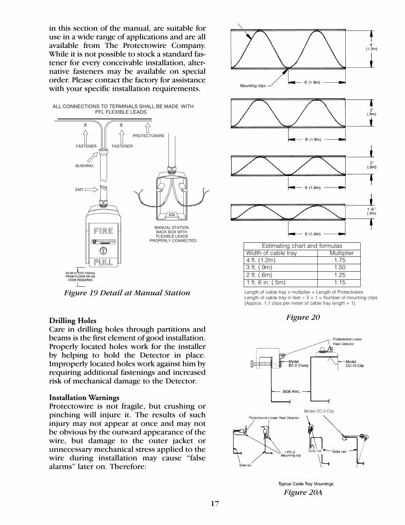
in this section of the manual, are suitable foruse in a wide range of applications and are allavailable from The Protectowire Company.While it is not possible to stock a standard fas-tener for every conceivable installation, alter-native fasteners may be available on specialorder. Please contact the factory for assistancewith your specific installation requirements.
Drilling HolesCare in drilling holes through partitions andbeams is the first element of good installation.Properly located holes work for the installerby helping to hold the Detector in place.Improperly located holes work against him byrequiring additional fastenings and increasedrisk of mechanical damage to the Detector.
Installation WarningsProtectowire is not fragile, but crushing orpinching will injure it. The results of suchinjury may not appear at once and may notbe obvious by the outward appearance of thewire, but damage to the outer jacket orunnecessary mechanical stress applied to thewire during installation may cause “falsealarms” later on. Therefore:
Figure 20
42-48 in. (107-122cm)FROM FLOOR OR AS
CODE REQUIRES
Figure 19 Detail at Manual Station
Figure 20A
Estimating chart and formulasWidth of cable tray Multiplier4 ft. (1.2m) 1.753 ft. (.9m) 1.502 ft. (.6m) 1.251 ft. 6 in. (.5m) 1.15Length of cable tray x multiplier = Length of ProtectowireLength of cable tray in feet ÷ 3 + 1 = Number of mounting clips(Approx. 1.1 clips per meter of cable tray length + 1)
Model CC-2 Clip
Side rail

18
• DO NOT leave it on the floor and walk onit or set ladders on it during installation.
• DO NOT install it with commercial fasten-ers unless specially approved by TheProtectowire Company.
• DO NOT place it where it will be subject tomechanical damage by equipment processes.
• DO NOT overtighten the fasteners as thismay breach the outer jacket or crush theinner insulation, causing unwanted alarms.All fasteners must allow the wire to expandand contract with temperature changes.
• DO NOT over stretch the Protectowire runs,some wire “sag” between fasteners is normal.
• DO NOT MAKE 90° BENDS IN THEDETECTOR.
• DO NOT hold the wire with pliers to makebends. All bends should be made with thefingers and consist of rounded turns witha minimum 2.5 inch (6.4 cm) radius.
• DO NOT use wire nuts or other similardevices. All connections must be made viaterminals and/or Protectowire approvedsplicing devices.
• DO NOT PAINT THIS DETECTOR, per ULand FM requirements.
Mechanical ProtectionWhenever the Detector comes within 6 feet(1.8m) of the floor, it should be enclosed in con-duit. This applies particularly to entry into manu-al stations, control units, zone or end-of-line junction boxes, and to all runs through floors.
Special ApplicationInstallations
“Where a detector is used in an applicationother than open area protection, the manu-facturer’s installation instructions shall be fol-lowed,” (NFPA 72-13). This section of themanual is intended to provide general guid-ance for installing Protectowire in several spe-cial applications such as cable trays, convey-ors, etc. Protectowire Linear Heat Detectorshould typically be installed as shown in thefollowing diagrams with reference to the cor-responding application.
Cable TraysFigure 20 illustrates Protectowire Linear HeatDetector installed in a sine wave pattern in acable tray. The Detector is run on top of all
Figure 21C
Figure 21D
Belt type (idler arm installation)Figure 21
Figure 21A
Figure 21B
ProtectowireLinear HeatDetector
Protectowire Linear Heat Detector
End-of-line resistor/box
End-of-line resistor/box
19
power and control cables in a tray and isspaced as shown in Figure 20. When additionalcables are pulled into the tray they should alsobe placed below the Detector.
Figure 20A illustrates the application of BC-2,CC-2, CC-10, and HPC-2 mounting clips tovarious types of cable trays.
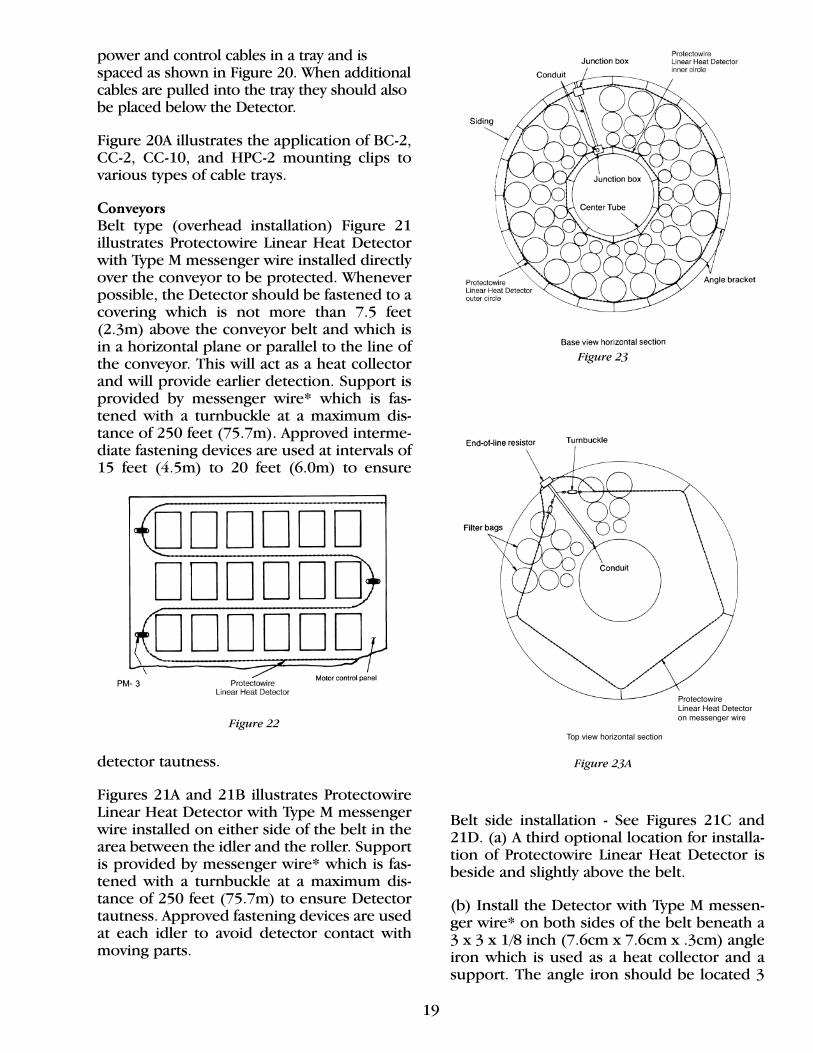
ConveyorsBelt type (overhead installation) Figure 21illustrates Protectowire Linear Heat Detectorwith Type M messenger wire installed directlyover the conveyor to be protected. Wheneverpossible, the Detector should be fastened to acovering which is not more than 7.5 feet(2.3m) above the conveyor belt and which isin a horizontal plane or parallel to the line ofthe conveyor. This will act as a heat collectorand will provide earlier detection. Support isprovided by messenger wire* which is fas-tened with a turnbuckle at a maximum dis-tance of 250 feet (75.7m). Approved interme-diate fastening devices are used at intervals of15 feet (4.5m) to 20 feet (6.0m) to ensure
detector tautness.
Figures 21A and 21B illustrates ProtectowireLinear Heat Detector with Type M messengerwire installed on either side of the belt in thearea between the idler and the roller. Supportis provided by messenger wire* which is fas-tened with a turnbuckle at a maximum dis-tance of 250 feet (75.7m) to ensure Detectortautness. Approved fastening devices are usedat each idler to avoid detector contact withmoving parts.
Belt side installation - See Figures 21C and21D. (a) A third optional location for installa-tion of Protectowire Linear Heat Detector isbeside and slightly above the belt.
(b) Install the Detector with Type M messen-ger wire* on both sides of the belt beneath a 3 x 3 x 1/8 inch (7.6cm x 7.6cm x .3cm) angleiron which is used as a heat collector and asupport. The angle iron should be located 3
Figure 23A
Figure 23
Figure 22
ProtectowireLinear Heat Detectoron messenger wire
Top view horizontal section
20
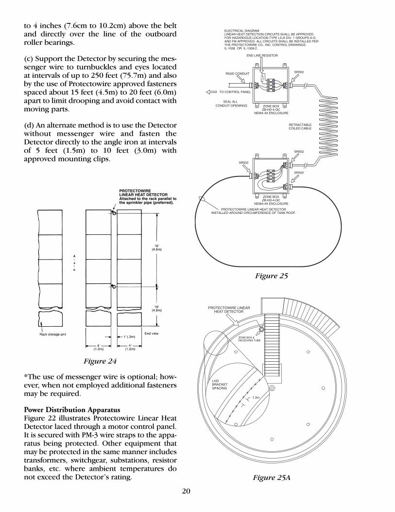
to 4 inches (7.6cm to 10.2cm) above the beltand directly over the line of the outboardroller bearings.
(c) Support the Detector by securing the mes-senger wire to turnbuckles and eyes locatedat intervals of up to 250 feet (75.7m) and alsoby the use of Protectowire approved fastenersspaced about 15 feet (4.5m) to 20 feet (6.0m)apart to limit drooping and avoid contact withmoving parts.
(d) An alternate method is to use the Detectorwithout messenger wire and fasten theDetector directly to the angle iron at intervalsof 5 feet (1.5m) to 10 feet (3.0m) withapproved mounting clips.
*The use of messenger wire is optional; how-ever, when not employed additional fastenersmay be required.
Power Distribution ApparatusFigure 22 illustrates Protectowire Linear HeatDetector laced through a motor control panel.It is secured with PM-3 wire straps to the appa-ratus being protected. Other equipment thatmay be protected in the same manner includestransformers, switchgear, substations, resistorbanks, etc. where ambient temperatures donot exceed the Detector’s rating.
Figure 25
Figure 25A
PROTECTOWIRE LINEAR HEAT DETECTORAttached to the rack parallel tothe sprinkler pipe (preferred).
Figure 24

21
Dust Collectors/BaghousesFigure 23 illustrates Protectowire Linear HeatDetector, supported by angle brackets,installed 30 inches (.8m) above the insidebase of a dust collector.
From the base junction box the Detector iscircled around the interior of the outer sidingthen run in conduit to the center tube wherethe Detector is circled as shown. The Detectoris then run in conduit to the top of the collec-tor where it is supported on messenger wirein the pattern shown in Figure 23A.
The Detector may also be installed around theblower motor frames for early detection of anoverheating condition.
Open Rack StorageFigure 24 illustrates Protectowire Linear HeatDetector installed in a section of a palletizedopen rack. When used in open single anddouble row racks protected by sprinklers, oneline of detection cable is needed at each in-rack sprinkler level. Wider racks may requireadditional Detector runs at each level. To min-imize the risk of mechanical damage to theDetector, the preferred method of mountingis to locate the Detector in the longitudinalflue space and attach it to the horizontal loadbeam at each sprinkler line level.
If the racks have no sprinklers and are morethan 16 feet (4.9m) high the Detector shouldbe run at two levels. If the racks are more than32 feet (9.8m) high, the Detector should berun at three levels, etc.
Floating Roof Fuel Storage TanksFigures 25, 25A and 25B illustrate ProtectowireLinear Heat Detector installed around the
Figure 26B
Figure 26
Figure 26AFigure 25B
22
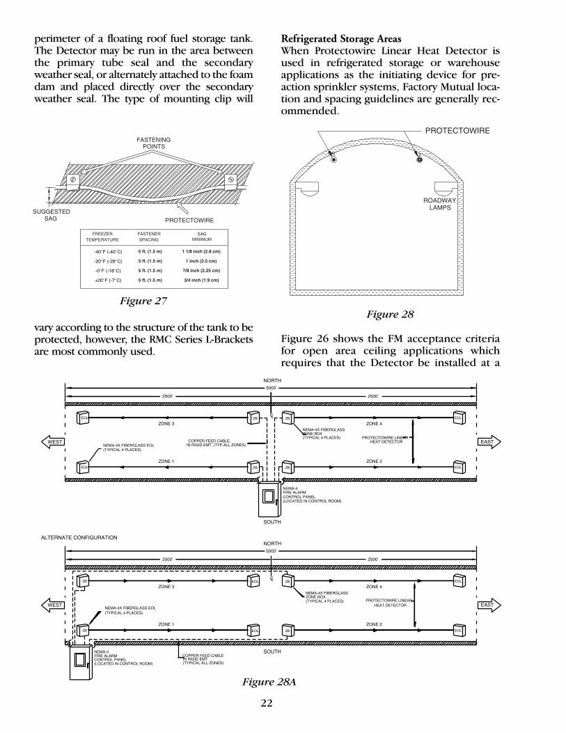
perimeter of a floating roof fuel storage tank.The Detector may be run in the area betweenthe primary tube seal and the secondary weather seal, or alternately attached to the foamdam and placed directly over the secondaryweather seal. The type of mounting clip will
vary according to the structure of the tank to beprotected, however, the RMC Series L-Bracketsare most commonly used.
Refrigerated Storage AreasWhen Protectowire Linear Heat Detector isused in refrigerated storage or warehouseapplications as the initiating device for pre-action sprinkler systems, Factory Mutual loca-tion and spacing guidelines are generally rec-ommended.
Figure 26 shows the FM acceptance criteriafor open area ceiling applications whichrequires that the Detector be installed at a
Figure 28Figure 27
5 ft. (1.5 m)
5 ft. (1.5 m)
5 ft. (1.5 m)
1 1/8 inch (2.8 cm)
5 ft. (1.5 m)
1 inch (2.5 cm)
7/8 inch (2.25 cm)
3/4 inch (1.9 cm)
SAGMINIMUM
�y
�y�y
��yy
��yy
Figure 28A
-40o F (-40oC)
-20o F (-29oC)
-0o F (-18oC)
+20oF (-7oC)
23
spacing not exceeding the allowable ceilingsprinkler spacing.
Rack detection systems should be installedbased upon the following criteria: For singlerow and double row racks, one line of detec-tion cable is needed at each in-rack sprinklerlevel. Locate the Protectowire detection cablein the longitudinal flue space and attach it tothe horizontal load beam at the sprinkler linelevel as illustrated in Figures 26A and 26B.
For multiple-row racks, a line of detectioncable is needed for each in-rack sprinklerline at each in-rack sprinkler level. Locate thedetection cable in each longitudinal fluespace and attach to the horizontal loadbeams at the sprinkler branch line levels.
Installation Advisory - When Protectowire isinstalled in refrigerated warehouses andfreezer applications, prior to chill-down, it isimportant to provide adequate slack or “sag”in the wire during the installation process inorder to avoid excessive stress on splicingconnections which may result in open circuittrouble conditions. This built-in slack isintended to compensate for the contractionof the Detector core which occurs during thereduction in temperature as the facility isbrought down to it’s subfreezing operatingtemperature.
The following chart (Figure 27) shows that in afreezer with an operating temperature of -40°F (-40°C), and fasteners placed every 5 feet(1.5m), the minimum sag between each set offasteners (as measured from the horizontal fas-tening plane) should be 1.125 inches (2.8cm).
TunnelsIn vehicular tunnel applications, ProtectowireLinear Heat Detector is typically installed on theceiling directly over the roadway as illustrated inFigures 28 and 28A. The system’s design may befurther enhanced by installing Protectowire inthe cable racks and equipment rooms whichhouse control and power cables for the tunnel’sventilation, communication, and signaling equip-ment. In cable runs, the Detector may beinstalled at each rack level in direct contact withthe cables. Because the Detector is a cable, it willeasily follow tray runs, change levels, and coververtical cable risers.
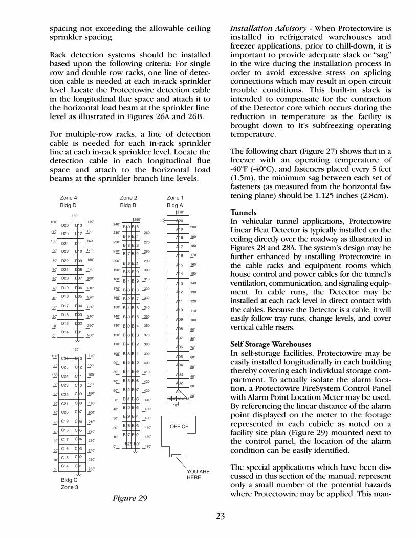
Self Storage WarehousesIn self-storage facilities, Protectowire may beeasily installed longitudinally in each buildingthereby covering each individual storage com-partment. To actually isolate the alarm loca-tion, a Protectowire FireSystem Control Panelwith Alarm Point Location Meter may be used.By referencing the linear distance of the alarmpoint displayed on the meter to the footagerepresented in each cubicle as noted on afacility site plan (Figure 29) mounted next tothe control panel, the location of the alarmcondition can be easily identified.
The special applications which have been dis-cussed in this section of the manual, representonly a small number of the potential hazardswhere Protectowire may be applied. This man-Figure 29
24
ual is intended to provide general principlesonly, therefore, the layout illustrations are “typ-ical” in nature, and may require modificationor adjustment based upon an actual engineer-ing evaluation of the specific hazard and it’srelevant factors. If your specific application isnot shown here, or if you need additionalproduct application information or assistance,please contact The Protectowire Company.
Inspection and TestingThis section covers the minimum recom-mended requirements for inspection, andtesting Protectowire Linear Heat Detector. Ingeneral, the requirements follow those rec-ommended in NFPA 72 for fixed-temperature,non-restorable line type heat detectors. Thismanual does not cover inspection, testing ormaintenance of other related devices or com-ponents of the fire alarm system.
Visual InspectionVisual inspections of the installed system shallbe made to ensure that there have been nochanges to the installation site, building struc-ture, or environmental factors that can effectequipment performance. Visual inspectionsshall be performed upon initial equipmentinstallation and at least semiannually thereafter.A more frequent schedule may be used ifrequired by the authority having jurisdiction.
Because Protectowire is frequently used in spe-cial applications where it may be inaccessiblefor safety considerations such as continuousprocess operations, or excessive height, it shallbe inspected during scheduled shutdownswhere approved by the authority having juris-diction. In all cases, however, the extendedinterval should not exceed 18 months.
Test FrequencyAs an initiating device, testing ProtectowireLinear Heat Detector should be an integralpart of a complete inspection and test pro-gram designed to ensure reliable operationand service of the entire fire detection/sup-pression system. Classified as a heat detector,Protectowire shall be tested upon initialinstallation and on an annual basis thereafter,unless a more frequent schedule is requiredby the local authority having jurisdiction.
TestingInspection, testing and maintenance of all firedetection/releasing systems shall be per-formed only by experienced and qualifiedpersonnel. All people and facilities thatreceive alarm, trouble or supervisory signalsshall be properly notified prior to the start oftesting and again after the testing has beenconcluded. Suppression systems shall besecured from inadvertent actuation by discon-necting electric actuators or releasing sole-noids, closing valves or taking other actions asappropriate for the specific system for theduration to the test. All system devices andreleasing components must be returned totheir normal condition after completion ofthe system testing.
Classified as a fixed-temperature, non-restor-able line type heat detector, Protectowire issubject to the following test method asdescribed in NFPA 72:
“Do not heat test. Test mechanically and elec-trically for function. Measure and record loopresistance. Investigate changes from accep-tance test.”
This test procedure may be easily accom-plished in Class B initiating circuits by usingthe built-in test button contained in some fac-tory supplied end-of-line zone boxes, or byusing a jumper wire to apply a short acrossthe end-of-line resistor to create an alarm. Ina Class A initiating circuit the recommendedprocedure is to remove the plus and minusreturn legs of the circuit at the control panelterminals. This action should cause a troublesignal at the control panel.
To create an alarm condition on the circuit(alarm overrides trouble), place a jumperacross the disconnected return leads. Thisaction will cause the necessary alarm conditionto activate the circuit and complete the test.
To measure loop resistance, place each circuitin alarm and leave the short across the detec-tion circuit as described above. Disconnecteach detection circuit’s wires from the termi-nals of the control panel. Place an ohm meteracross the disconnected zone wires (out +and out –) and record the resistance mea-sured. Compare these values at each annual

25
testing. Any change in loop resistance shouldbe investigated for possible deterioration ofthe inner conductors with particular attentiongiven to termination points, in-line splices orareas of the Detector where the outer jackethas been compromised or damaged.
In some areas, local codes or the authority hav-ing jurisdiction may require a heat test in lieu of the recommended electrical test procedure.A simple method of heat testing a non-restor-able fixed-temperature linear detector, is toselect a convenient location in the detectionloop and using approved splicing connectorsor zone boxes, install a small test length of lin-ear detector between the splice connectionpoints. The test area may be heated by what-ever means required to satisfy the test require-ments. When finished, the heat actuated sectioncan be removed and replaced with a new pieceof detector, thereby restoring the system backto normal operation.
Protectowire TestEquipmentTo assist the installer and service personnel inlocating heat actuated sections of the Protecto-wire Linear Heat Detector, or portions of theDetector which have been shorted due tomechanical damage, two portable test instru-ments are available from The ProtectowireCompany.
APL-90 Meter AdapterThe APL-90 Meter Adapter is designed to con-vert any Digital Multimeter which contains a200 millivolt scale, to a Protectowire AlarmPoint Location Meter. It enables the user todetermine the distance of the alarm point(short) from the start of the Protectowire por-tion of the detection circuit. The APL-90 ishoused in a high impact plastic case whichmeasures 3.75 x 2.50 x 1 inch (9.5 x 6.4 x 2.5cm). The unit weighs 4 ounces (113 g), and ispowered by one 9 volt Type 1604 battery,which provides sufficient power for approxi-mately 100 hours of use.
The Adapter is equipped with a standard sizedouble banana plug with male probes spaced.75 of an inch (1.9 cm) on center. This plugprovides the means to connect into a Digital
Multimeter. A power ON/OFF switch, PowerOn LED indicator, and Calibration Check/Testswitch are also provided. A programmablemicro jumper located inside the Adapter isprovided so that the user may easily selecteither Feet or Meters as the unit of measure-ment to be digitally displayed.
MFL-92 Fault Locator SystemThe Fault Locator System is designed todetect and locate the alarm point (shorted)on the Protectowire Linear Heat Detector.Unlike the APL-90 Meter Adapter which deter-mines the alarm location based upon conduc-tor resistance readings which are subject tovariations, the Fault Locator System is able tolocate the exact location of the actuated sec-tion by using an advanced audio signalingtechnique.
The MFL-92 consists of two modular units. ATone Generator Model FDG-92 and a ToneReceiver Model FDR-92. Both modules arehoused in durable ABS plastic enclosureseach small enough to be hand carried. Eachmodule weighs less than 8 ounces (227 g).
The FDR-92 Tone Receiver is powered by one9 volt Type 1604 battery with an average life of50 hours. The unit contains a tone signal pick-up LED indicator and two phone jacks. Onefor the exploring Pickup Head and one for anoptional earphone for use in areas where theambient noise level is high.
The second module which is the FDG-92 ToneGenerator, is powered by one 9 volt Type1604A Alkaline battery. Depending upon theload that the device is connected to, the expect-ed battery life will range from 4 to 20 hours.
Conversion Factors• 1 inch = 2.54 cm• 1 foot = 3.05 decimeters• 1 millimeter = .04 inches• 1 centimeter = .39 inches• 1 meter = 3.28 feet• F° = Degrees Fahrenheit F° = 9/5C° + 32°• C° =Degrees Celsius (Centigrade) C° = 5/9 (F°–32°)
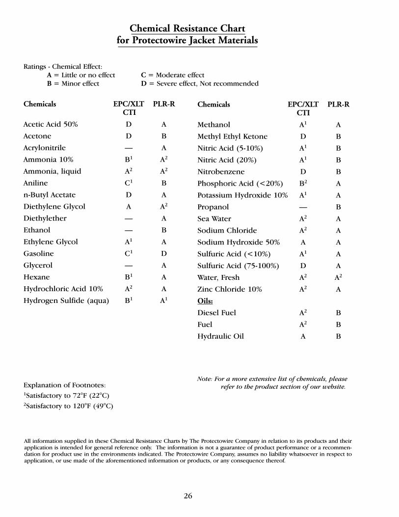
26
Chemical Resistance Chartfor Protectowire Jacket Materials
Ratings - Chemical Effect:A = Little or no effect C = Moderate effectB = Minor effect D = Severe effect, Not recommended
Chemicals EPC/XLT PLR-RCTI
Acetic Acid 50% D A
Acetone D B
Acrylonitrile — A
Ammonia 10% B1 A2
Ammonia, liquid A2 A2
Aniline C1 B
n-Butyl Acetate D A
Diethylene Glycol A A2
Diethylether — A
Ethanol — B
Ethylene Glycol A1 A
Gasoline C1 D
Glycerol — A
Hexane B1 A
Hydrochloric Acid 10% A2 A
Hydrogen Sulfide (aqua) B1 A1
Chemicals EPC/XLT PLR-RCTI
Methanol A1 A
Methyl Ethyl Ketone D B
Nitric Acid (5-10%) A1 B
Nitric Acid (20%) A1 B
Nitrobenzene D B
Phosphoric Acid (<20%) B2 A
Potassium Hydroxide 10% A1 A
Propanol — B
Sea Water A2 A
Sodium Chloride A2 A
Sodium Hydroxide 50% A A
Sulfuric Acid (<10%) A1 A
Sulfuric Acid (75-100%) D A
Water, Fresh A2 A2
Zinc Chloride 10% A2 A
Oils:
Diesel Fuel A2 B
Fuel A2 B
Hydraulic Oil A B
Explanation of Footnotes:1Satisfactory to 72°F (22°C)2Satisfactory to 120°F (49°C)
All information supplied in these Chemical Resistance Charts by The Protectowire Company in relation to its products and theirapplication is intended for general reference only. The information is not a guarantee of product performance or a recommen-dation for product use in the environments indicated. The Protectowire Company, assumes no liability whatsoever in respect toapplication, or use made of the aforementioned information or products, or any consequence thereof.
Note: For a more extensive list of chemicals, please refer to the product section of our website.
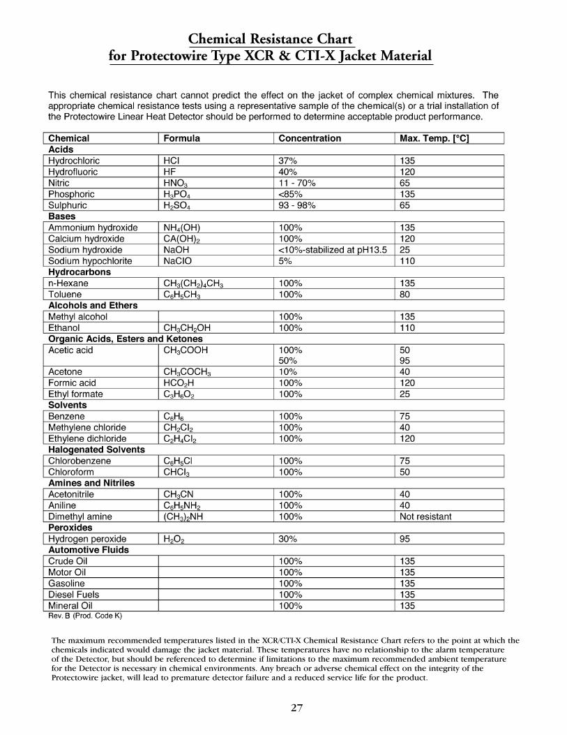
27
The maximum recommended temperatures listed in the XCR/CTI-X Chemical Resistance Chart refers to the point at which the chemicals indicated would damage the jacket material. These temperatures have no relationship to the alarm temperature of the Detector, but should be referenced to determine if limitations to the maximum recommended ambient temperature for the Detector is necessary in chemical environments. Any breach or adverse chemical effect on the integrity of theProtectowire jacket, will lead to premature detector failure and a reduced service life for the product.
Chemical Resistance Chartfor Protectowire Type XCR & CTI-X Jacket Material

Protectowire CTI Linear Heat Detector
CTI Installation Hardware
DS 8476N-0815 (1C)
TYPE CTI – VINYL JACKET
CTI-155 155° (68°C)Max. Recommended Ambient Temp 115° F (46° C)
CTI-190 190° (88°C)Max. Recommended Ambient Temp 150° F (66° C)
CTI-220 220° (105°C)Max. Recommended Ambient Temp 175° F (79° C)
CTI-280 280° (138°C)Max. Recommended Ambient Temp 200° F (93° C)
CTI-356 356° (180°C)Max. Recommended Ambient Temp 221° F (105° C)
TYPE CTI-XFLUOROPOLYMER JACKET
CTI-155X 155° (68°C)Max. Recommended Ambient Temp 115°F (46°C)
CTI-190X 190° (88°C)Max. Recommended Ambient Temp 150°F (66°C)
CTI-220X 220° (105°C)Max. Recommended Ambient Temp 175°F (79°C)
CTI-280X 280° (138°C)Max. Recommended Ambient Temp 200°F (93°C)
CTI-356X 356° (180°C)Max. Recommended Ambient Temp 250°F (121°C)
CTICSplice Connector
PM-3Pipe Strap
BC-2Beam ClampWAW Clip
OHS-SSStainless Steel Line ClipHPC-2
Cable Tray Clip
CC-2Cable Tray Clip
The Protectowire Company, Inc.60 Washington St., Pembroke, MA 02359 U.S.A.781-826-3878, Fax 781-826-2045Web: http://www.protectowire.come-mail: [email protected] hazard fire detection systems
Note: Colors shown are for illustrative purposes only. Actual jacket colors may vary.
Protectowire CTI Linear Heat Detector
CTI Installation Hardware
DS 8476N-0815 (1C)
TYPE CTI – VINYL JACKET
CTI-155 155° (68°C)Max. Recommended Ambient Temp 115° F (46° C)
CTI-190 190° (88°C)Max. Recommended Ambient Temp 150° F (66° C)
CTI-220 220° (105°C)Max. Recommended Ambient Temp 175° F (79° C)
CTI-280 280° (138°C)Max. Recommended Ambient Temp 200° F (93° C)
CTI-356 356° (180°C)Max. Recommended Ambient Temp 221° F (105° C)
TYPE CTI-XFLUOROPOLYMER JACKET
CTI-155X 155° (68°C)Max. Recommended Ambient Temp 115°F (46°C)
CTI-190X 190° (88°C)Max. Recommended Ambient Temp 150°F (66°C)
CTI-220X 220° (105°C)Max. Recommended Ambient Temp 175°F (79°C)
CTI-280X 280° (138°C)Max. Recommended Ambient Temp 200°F (93°C)
CTI-356X 356° (180°C)Max. Recommended Ambient Temp 250°F (121°C)
CTICSplice Connector
PM-3Pipe Strap
BC-2Beam ClampWAW Clip
OHS-SSStainless Steel Line ClipHPC-2
Cable Tray Clip
CC-2Cable Tray Clip
The Protectowire Company, Inc.60 Washington St., Pembroke, MA 02359 U.S.A.781-826-3878, Fax 781-826-2045Web: http://www.protectowire.come-mail: [email protected] hazard fire detection systems
MAN2001M-0817 (1C)
60 Washington Street, Pembroke, MA 02359 U.S.A.
AN ISO 9001 REGISTERED COMPANY©2015 The Protectowire Co., Inc.