SKRIPSI – TK 141581 PENGARUH KECEPATAN IMPELLER TERHADAP ...

INSTALLATION INSTRUCTIONSFOR FURTHER QUESTIONS, PLEASE CALL 775‐440‐2025
JENSEN WATER RESOURCES
521 Dunn Circle, Sparks, NV 89431
JensenPumps.com
March 2016

Submersible Pump StationInstallation Instructions Page 2
Figure 1: This illustration shows a complete pump station material delivery as arranged on one flat bed truck.

Table of Contents
• Lift Station Identification
• Bracket Orientation
• Bracket Installation
• Base Elbow Orientation
• Base Elbow Installation
• Station Layout Identification
• Mechanical Joint Sleeve Installation
• Force Main Installation
• Intermediate Guide Rail Bracket Installation
• Pipe Bracing Installation
• Pump Installation
• Electrical Cable Management
• Control Panel Installation
• Appendix A – Junction Box Installation
• Appendix B – Pre‐commissioning Check List
4
5
6
7
8
9
10
11
12
13
14
15
16
18
20
Submersible Pump StationInstallation Instructions Page 3

PUMP
STATIONS
521 DUNN CIRCLE, SPARKS, NV 89431
JensenPumps.com
(855) 468-5600
Copyright Information ©2011 Jensen
Precast All Rights Reserved. All
materials appearing as Jensen Precast
documents and the like are propriety
work product and are protected under
U.S. copyright and other laws. Unless
in conjunction with business conducted
with Jensen Precast, any use of
Jensen Precast work product without
express, written consent is prohibited
and recipient is prohibited from
distributing any and all work product to
non-approved third parties under
penalty of civil action.
PROJECT:
STATION IDENTIFICATION
DETAIL DRAWING
C:\Vault\Jobs\Standard Details\Installation Procedures\Identification Sheet\Station ID Assembly.iam
DATE: DRAWN BY: SHEET NO:
MARCH 2016 BP1 of 1
PUMP STATION IDENTIFICATION
1. WET WELL: WET UTILITY STRUCTURE WHICH CONTAINS PUMPS, SLIDE RAIL SYSTEM, AND LEVEL SENSORS.
2. VALVE VAULT: DRY STRUCTURE WHICH CONTAINS VALVES, PIPING AND FITTINGS.
3. DISCHARGE STRUCTURE: UPSTREAM LOCATION AT WHICH THE PUMP FORCEMAIN ENDS AND SYSTEM TURNS TO GRAVITY,
TYPICALLY A MANHOLE.
4. FINISH GRADE ELEVATION: ELEVATION OF GROUND LEVEL AFTER PROJECT COMPLETION.
5. WET WELL RIM ELEVATION: ELEVATION OF TOP OF WET WELL AFTER PROJECT COMPLETION. TYPICALLY EQUAL TO FINISH
GRADE.
6. GRAVITY INLET INVERT ELEVATION: ELEVATION OF INLET PIPE TO THE PUMP STATION. TYPICALLY FROM A GRAVITY PIPE,
BUT CAN BE A FORCEMAIN IF COMING FROM A PRESSURIZED SOURCE SUCH AS A PUMP STATION.
7. SUBMERSIBLE PUMP: PUMP IN WET WELL THAT WILL BE SUBMERGED DURING NORMAL OPERATION.
8. BASE ELBOW: PERMANENT BASE IN WET WELL WHICH ALLOWS FOR PUMP COUPLING WHEN PUMP IS PLACED IN WET WELL.
9. PUMP FORCEMAIN: PRESSURIZED PIPE THAT CARRIES WATER FROM PUMP TO DISCHARGE STRUCTURE.
10. OUTFALL ELEVATION: ELEVATION OF FORCEMAIN PIPE TERMINATION AT THE DISCHARGE STRUCTURE.
11. DRAIN PIPE: DRAIN FROM VALVE VAULT TO WET WELL, PREVENTS WATER BUILD UP IN VALVE VAULT.
JENSEN PUMP STATION
SYSTEM IDENTIFICATION DRAWING
PUMP STATION SPECIFICATIONS
PART 1 - GENERAL
1.1 SECTION INCLUDES
A. Site assembled and tested precast wastewater utility pumping stations, including:
1. Precast concrete wet-well and valve vault.
2. Pumps and mountings.
3. Control panel.
4. Piping/Valves/Fittings integral to pumping station.
5. Pumping station design services.
1.2 ACTION SUBMITTALS
A. Product Data: Provide manufacturer's technical data including station capacities and operating characteristics.
B. Pump Performance Curves.
C. Shop Drawings: Show fabrication and installation details.
1.3 CLOSEOUT SUBMITTALS
A. Field Reports: Provide quality-control test reports documenting station operation performance.
B. Operation and Maintenance Manual: Include approved submittals and schedule for maintenance requirements.
1.4 QUALITY ASSURANCE
A. Manufacturer Qualifications: NPCA-certified plant, with experience and demonstrated capability to produce work specified
in this Section
B. Electrical Components, Devices, and Accessories: Listed and labeled as defined in NFPA 70, Article 100, by a testing
agency acceptable to authorities having jurisdiction, and marked for intended use.
1.5 WARRANTY
A. Manufacturer's Warranty: Manufacturer's standard form in which manufacturer agrees to repair or replace components of
pumping stations that fail in materials or workmanship within specified warranty period.
1. Failures include, but are not limited to, the following:
a. Structural failures including precast concrete structures, hatches, and other accessories.
b. Faulty operation of pumps, controls, or pumping and piping system accessories.
c. Deterioration of metals, metal finishes, and other materials beyond normal use.
2. Warranty Period for Precast Concrete Structures: One year from date of Substantial Completion.
3. Warranty Period for Pumps: One year from date of Substantial Completion.
4. Warranty Period for Control Panel: One year from date of Substantial Completion.
PART 2 - PRODUCTS
2.1 MANUFACTURER
A. Basis of Design: Provide site assembled precast wastewater utility pumping station, including specified controls, pumps,
valves, internal piping, and precast concrete well by manufactured and furnished by Jensen Precast, Sacramento, CA, (775)
352-6343, [email protected], www.jensenengineeredsystems.com.
2.2 PRECAST CONCRETE STRUCTURES
A. Round Precast Concrete Wells: ASTM C 890, precast, reinforced concrete.
1. Wall Thickness, Base Thickness, and Cover Slab shall be designed by the Precast Concrete Company and Stamped by a
licensed Professional Engineer
2. Flexible Resilient Pipe Connectors: ASTM C 923.
B. Precast Concrete Valve Vault: ASTM C 890, precast, reinforced concrete.
1. Base Section: 6-inch minimum thickness for floor slab and 5-inch minimum thickness for walls.
2. Flexible Resilient Pipe Connectors: ASTM C 923.
2.3 PRECAST CONCRETE MATERIALS AND MIX DESIGN
A. General: Precast concrete according to ACI 318.
B. Concrete Design Mix: 4,000 psi minimum, with 0.45 maximum water/cementitious materials ratio.
2.4 ACCESS DOORS AND FRAMES
A. Wet Well Access Door: Aluminum Angle Frame, Single Door, Pedestrian 300 PSF Loading, with Slamlock, Removable
Outside Key Fixed inside handle, SS tamperproof hinges, and Nut Rails on Front and Back
B. Valve Vault Access Door: Aluminum Angle Frame, Single Door, Pedestrian 300 PSF Loading, with Slamlock, Removable
Outside Key Fixed inside handle, SS tamperproof hinges, and Nut Rails on Front and Back
2.5 WET-WELL ACCESSORIES
A. Guide Rail Assembly: Dual guide rail assembly, stainless steel, Type 304, with pump guide brackets configured to match
requirements of selected pumps. Single guide rail assembly will not be accepted.
B. Flexible Resilient Pipe Connectors: Flexible connector, ASTM C 923.
C. Liners:
1. A protective liner shall be used whenever a precast concrete manhole or structure is used in a sanitary or light industrial
sewer system in which the potential for corrosive attack to the concrete substrate exists.
2. The liner shall be the Dura Plate 100 liner as manufactured by A-LOK® Products, Inc., Tullytown, PA or approved equal.
3. The design of the liner shall provide a corrosion protective barrier permanetly embeded to the inside well of the structure.
2.6 SUBMERSIBLE WASTEWATER NON CLOG PUMPS
A. PERFORMANCE GUARANTEE: The pump shall be capable of delivering raw, unscreened sewage at: 50 GPM at 40 FT TDH.
B. Scope: Furnish and install 2 qty. HOMA Model GRP 16/3 FM Electric Submersible Grinder Pump(s), each consisting of a
single-stage, non-clog centrifugal pump, with a cutter attachment, close coupled by a common shaft to a squirrel cage,
induction type electric motor, assembled in a single body, watertight aggregate, suitable for wet well.
C. Pump Design: The liquid end shall be a centrifugal pump with a rotating cutter mounted on the shaft
immediately adjacent to the impeller. The stationary cutter disk shall be mounted in an axially adjustable
bottom plate. A short overhang shaft, shared by the rotating cutter, impeller and motor, will have generous
shoulder fillet radii to minimize stress concentration and fatigue. The shaft shall be supported by anti-friction
bearings. The lower bearing shall be a double-row, deep groove ball bearing, axially retained to sustain both
axial and radial loads. The upper bearing shall be a single-row, deep groove ball bearing, axially floating to
sustain radial loads only. Power cables shall enter the motor through a Potted Cable Inlet Assembly in a side
entry chamber integral with the motor housing. The cable entry design shall ensure a watertight and
submersible seal. The entry shall include an elastomer grommet that is flanked by washers. Watertight
integrity shall additionally be maintained by a mechanical shaft seal, and by O Rings, confined within closely
fitted, high surface quality rabbet joints, compressed to the prescribed dimension only by metal to metal
contact. The impeller shall be cast in one piece and of the multi-vane, centrifugal (radial) design.
D. Guide Rail Base Assembly: An Autocoupling assembly shall be employed to eliminates the need for
entering the wet well to service pumps. The system shall allow the lowering of the pump unit(s) into the well
along rigid guide pipes, resulting in a self-engaging, firm, leakproof coupling of the volute outlet to a receiving
base anchored to the floor which forms the discharge pipe connection. To assure a leakproof junction between
movable and stationary components, a resilient seal ring shall be employed which is easily replaceable as part
of the pump assembly, is axially and evenly compressed upon contact. Metal-to-metal contact faces shall not be
allowed. Once seated, the pump shall be entirely supported by the Autocoupling Base, without any reliance on
additional supports.
E. Pump Construction: Major castings: ASTM A48 Class 40B Cast Iron- The cutter parts shall be made of
Stainless Steel similar to AISI 440C, alloyed with cobalt, vanadium and molybdenum for a hardness of 55
Rockwell C minimum, to provide lasting abrasion resistance.- Shaft: AISI 430F Stainless Steel. - Fasteners:
AISI 304 Stainless Steel. - All O-Rings: Nitrile Rubber. - Shaft Seals: Impeller side; Silicon Carbide/Silicon
Carbide and Motor side; Radial Lip Seal.. Cable Jacket: Chloroprene Rubber. Exterior Protective Coating: High
Build Epoxy.
F. Seal Probe: A two-wire conductive seal probe shall be provided with pump. Probe shall be mounted into
mechanical seal chamber and shall be accessible without disassembly of pump. Internal seal probe designs
which require disassembly of pump for inspection shall not be permitted. When interlocked with control panel,
probe shall indicate the presence of contaminants within mechanical seal chamber.
G. Electric Motor: Each pump shall be driven by a Submersible Squirrel Cage type Electric Motor, rated at 1.5
HP, 3450 RPM 230 Volts 3 Phase. Motor shall be NEMA Design B for continuous duty, capable of sustaining 10
starts per hour. The pump and motor shall be produced by one manufacturer and shall be of submersible
design. All stator windings and leads shall be insulated with moisture resistant Class F insulation, capable of
withstanding l55oC Max. temperature, dipped and baked three times. Upon assembly, the stator shall be
heat-shrink fitted into the stator housing; the use of bolts, pins or other fastening devices which would require
penetration of the stator housing, shall not be acceptable. In each phase winding there shall be embedded a
temperature sensor, wired in series. Any of these thermal sensors shall cut out electric power if the
temperature in its winding exceeds 140oC, but shall automatically reset when the winding temperature returns
to normal. The motor shall have a SF (Service Factor) of 1.15 and shall be non-overloading for the selected
performance curve. Full load current shall not exceed 6.2 FLA at 230 Volts. Single Phase motors shall be of the
run capacitor type, to deliver high starting torque.Motor shall be approved for us in Hazardous (Classified)
areas. Pumps shall be suitable for operation in Class I, Division 1 Groups C & D Areas only, and shall be
approved by Factory Mutual (FM) for use in the area classification indicated.
2.7 PUMP STATION CONTROLS
A. Control Sequence of Operation: The system shall use a Pressure Transducer with 2 back up floats. The Seimens
LOGO PLC shall monitor and control the pumps using a pressure transducer and two back-up float switches. A local
interface is provided for system status, data and parameter adjustment.
B. Control Panel: Complying with UL 698A, with weatherproof enclosure, covered compartments sized to
accommodate controllers, circuit breakers, transformers, alternators, and programmable logic controller. Basis of Design
Product: Orenco Systems, Inc.,MVP-DAX Custom Panel.
1. PANEL OPERATION: 2 PUMPS, PRESSURE TRANSDUCER, 2 FLOAT BACK UP, ALTERNATING DUPLEX SYSTEM
2. NEMA 4X FIBERGLASS ENCLOSURE
3. DEAD FRONT PANEL DOOR
4. CONTROLS TRANSFORMER
5. MOTOR CIRCUIT BREAKER FOR EACH PUMP
6. NUMBERED TERMINAL BLOCKS
7. HAND-OFF-AUTO SWITCH FOR EACH PUMP
8. ALARMS (LIGHTS TO BE MOUNTED ON DEAD FRONT PANEL DOOR)
9. PUMP RUN LIGHTS, ONE FOR EACH PUMP (GREEN LENS)
10. DRY CONTACT FOR ALARMS (ONE PAIR OF CONTACTS TO REPORT ALL ALARMS)
11. DRY CONTACT FOR PUMP RUN (ONE PAIR OF CONTACTS TO REPORT EITHER PUMP RUNNING)
C. Level Control System: Shall be a pressure transducer with 2 back up floats. The pressure transducer shall be by
Dwyer Instruments or Equal. The back-up floats shall be Internally weighted non-mercury floats.
2.8 PIPING AND VALVES
A. Ductile-Iron, Mechanical-Joint Pipe and Fittings
1. Ductile-Iron Pipe: AWWA C151/A21.51, with mechanical-joint bell and plain spigot end unless flanged ends are
indicated.
a. Provide flanged ends within well and vault.
2. Ductile-Iron Fittings: AWWA C110/A21.10, mechanical-joint, ductile- or gray-iron standard pattern or AWWA
C153/A21.53, ductile-iron compact pattern.
3. Glands, Gaskets, and Bolts: AWWA C111/A21.11, ductile- or gray-iron glands, rubber gaskets, and steel bolts.
4. Application: Buried service between well and vault.
B. Swing Check Valves: The valve body and cover shall be constructed of ASTM A536 Grade 65-45-12 ductile iron
VAL-MATIC SWINGFLEX CHECK VALVE 503A or Equal.
C. Eccentric Plug Valves: The valve body and cover shall be constructed of ASTM A126 Class B cast iron for working
pressures up to 175 psig Direct and 100 Reverse. The words "SEAT END" shall be cast on the exterior of the body seat
end . VAL-MATIC CAM-CENTRIC PLUG VALVE 5803 w/ 2" Square Nut
PART 3 - EXECUTION
3.1 PRECAST CONCRETE STRUCTURES
A. Install precast concrete structure sections with sealants per ASTM C 891.
3.2 FIELD QUALITY CONTROL
A. Perform tests and inspections and prepare test reports.
1. Manufacturer's Field Service: Engage a pump station manufacturer's authorized service representative to assist in
testing and startup.
B. Tests and Inspections:
1. Test completed piping systems according to requirements of authorities having jurisdiction. Submit reports.
2. After installing wastewater pumping stations and after electrical circuitry has been energized, test pumps and
controls for compliance with requirements.
3. After electrical circuitry has been energized, start units to confirm the station can run at pre-specified design
parameters.
4. Test piping for leaks and defects.
5. Test and adjust controls and safeties.
C. Remove and replace components of the wastewater pumping stations that do not pass tests and inspections and
retest as specified above.
1.) WET WELL
2.) VALVE VAULT
3.) DISCHARGE
STRUCTURE
6.) GRAVITY INLET
INVERT
9.) PUMP FORCE MAIN
7.) SUBMERSIBLE
PUMP
8.) BASE ELBOW FOR
AUTOCOUPLING SYSTEM
4.) FINISH GRADE ELEVATION
5.) WET WELL RIM ELEVATION
FORCE MAIN
LENGTH
10.) OUTFALL ELEVATION
11.) DRAIN PIPE
SINGLE DOOR HATCH
DOUBLE DOOR
HATCH

Submersible Pump StationInstallation Instructions Page 5
PART LIST 1
PART DESCRIPTION
1 PRECAST CONCRETE FLAT TOP
2 PRECAST CONCRETE TOP BARREL
3 UPPER GUIDE RAIL ASSEMBLY
4 FLOAT BRACKET ASSEMBLY
5 CAST‐IN HATCH
6 FACTORY INSTALLED NUTRAIL
1
43
2
5
6
Figure 2: This image shows upper guide rail bracket
orientation when the flat top includes a single door hatch.
Figure 3: Shown here is the upper guide rail bracket
orientation when the flat top has a double door hatch.
Figure 4: The flat top must be oriented such that the long axis of the access hatch is perpendicular to the direction of the force main.
4
3

Submersible Pump StationInstallation Instructions Page 6
PART LIST 2
PART QTY DESCRIPTION
1 N.A. FACTORY INSTALLED NUT RAIL
2 5 SS CHANNEL NUT
3 2 UPPER GUIDE RAIL BRACKET
4 5 SS HEX BOLT
5 4 GUIDE RAIL PIPE
6 1 SS FLOAT BRACKET
7 2 OPTI‐FLOAT LEVEL SENSOR
8 1 PRESSURE TRANSDUCER
12
3 4
5
STEPS FOR PART LIST 21. Install upper guide rail bracket on the force
main side of wet well.a) Leave the SS Hex Head bolts loose.
2. Install float bracket on opposite side of accesshatch.
3. If there is no nut rail installed, make sure thatall brackets are installed no farther than 6”down the skirt of the frame.
Pressure transducer handling: • The pressure transducer is to be kept in a moisture free environment until it can be
installed and pulled directly to the control panel.• Please do not splice the cable and/or install in junction box! If a longer cable is needed,
contact us at 775‐440‐2025.• A stilling well may be used; consult Jensen Pump Stations before installing the stilling well
pipe.
12 6
7
8
Figure 5: Upper guide rail bracket installation.
Figure 6: Float bracket installation.
IMPORTANT!

STEPS FOR PART LIST 3
1. Align the center of the discharge flange of the pump base elbow, the upper guiderail bracket, and the center of the core hole for the force main discharge. (Figure 7on this page)
2. Using a plumb bob, align the upper guide rail grommets with the mounting holesfor the guide rail in the base elbow. (Figure 8 on this page)
3. Figure 9 is described further on the following page.
Submersible Pump StationInstallation Instructions Page 7
PART LIST 3
PART DESCRIPTION
1 UPPER GUIDE RAIL BRACKET
2 CORE HOLE (FORCE MAIN DISCHARGE)
3 PLUMB BOB
4 PUMP BASE ELBOW
5 SS WEDGE ANCHOR4
2
Figure 7
2
3
1
Figure 8
*Double door hatch orientation – see page #3*
DISCHARGE FLANGE OF PUMP BASE ELBOW
MOUNTING HOLES FOR GUIDE RAIL
5
Figure 9

Submersible Pump StationInstallation Instructions Page 8
STEPS FOR FIGURE 10
1. Drill hole for wedge anchors with Roto‐Hammer.
a) WARNING: Take care to not drill all the way through the concrete base.
2. Install wedge anchors.
3. Install base elbows.
4. Tighten wedge anchor hex head.
Figure 10
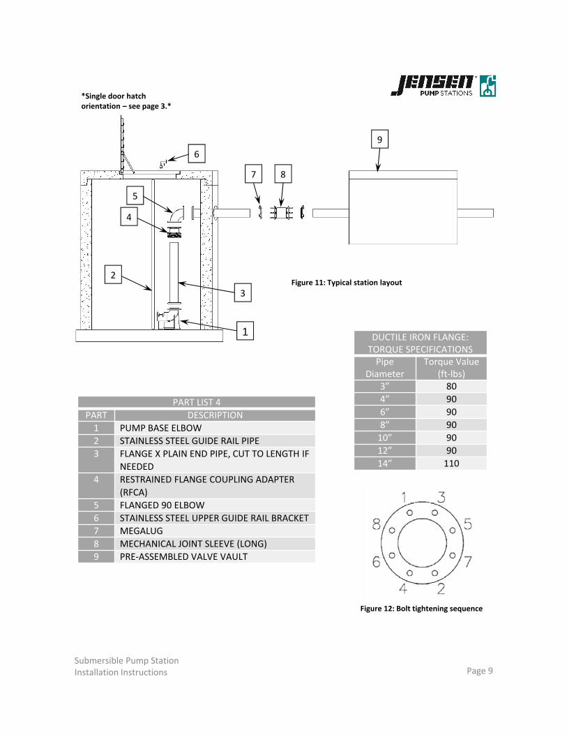
Submersible Pump StationInstallation Instructions Page 9
DUCTILE IRON FLANGE: TORQUE SPECIFICATIONSPipe
DiameterTorque Value
(ft‐lbs)3” 80
4” 90
6” 90
8” 90
10” 90
12” 90
14” 110
Figure 12: Bolt tightening sequence
PART LIST 4
PART DESCRIPTION
1 PUMP BASE ELBOW
2 STAINLESS STEEL GUIDE RAIL PIPE
3 FLANGE X PLAIN END PIPE, CUT TO LENGTH IF
NEEDED
4 RESTRAINED FLANGE COUPLING ADAPTER
(RFCA)
5 FLANGED 90 ELBOW
6 STAINLESS STEEL UPPER GUIDE RAIL BRACKET
7 MEGALUG
8 MECHANICAL JOINT SLEEVE (LONG)
9 PRE‐ASSEMBLED VALVE VAULT
Figure 11: Typical station layout
1
2
3
6
4
5
7 8
9
*Single door hatch orientation – see page 3.*

Submersible Pump StationInstallation Instructions Page 10
MECHANICAL JOINT SLEEVES
PRE‐ASSEMBLEDVALVE VAULT
Figure 13: MJ Sleeve installation
STEPS FOR FIGURE 131. Slide the Mega Lugs and the Joint Sleeves onto the plain ends of the pipes coming out
of the valve vault. 2. Once the pipes from the wet well are placed (see Page 9), center the sleeves between
the connection and tighten the bolts.
STEP 3
STEP 4
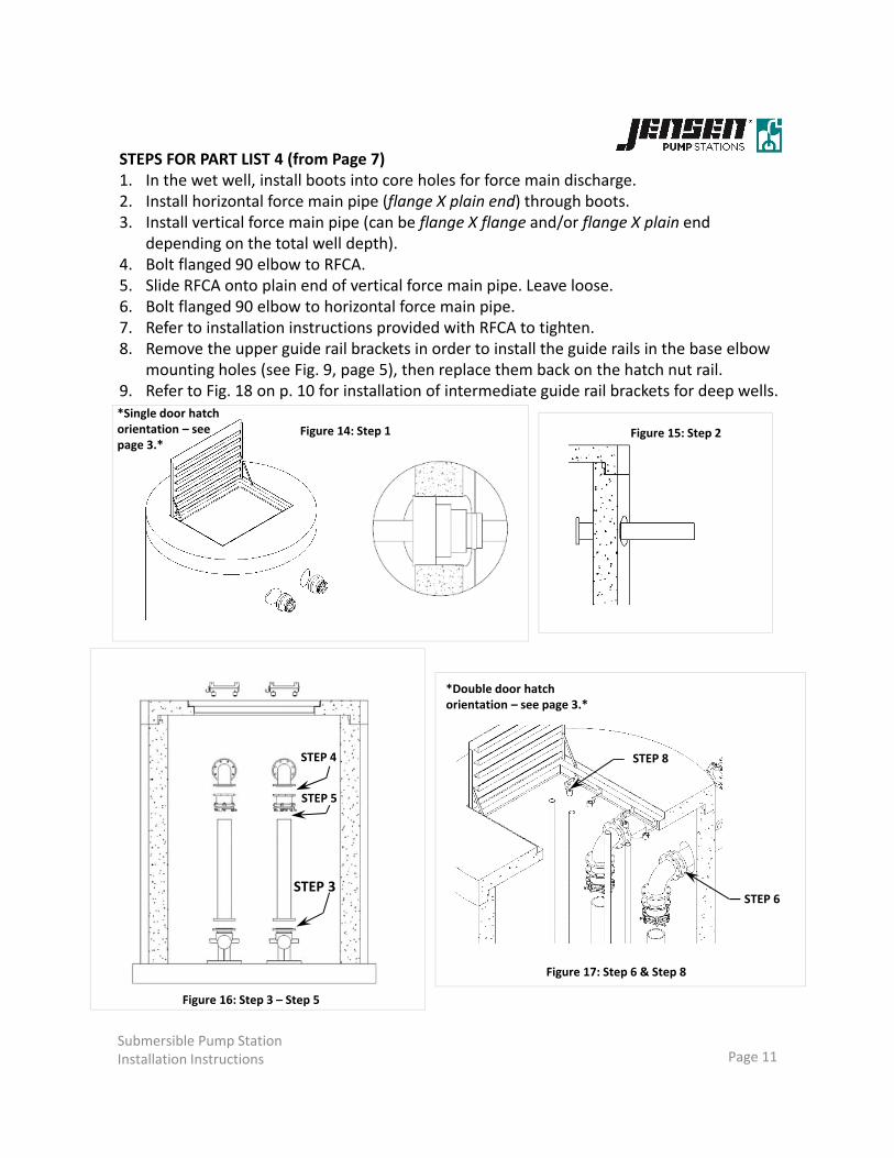
Submersible Pump StationInstallation Instructions Page 11
Figure 15: Step 2
STEPS FOR PART LIST 4 (from Page 7)1. In the wet well, install boots into core holes for force main discharge.2. Install horizontal force main pipe (flange X plain end) through boots.3. Install vertical force main pipe (can be flange X flange and/or flange X plain end
depending on the total well depth).4. Bolt flanged 90 elbow to RFCA.5. Slide RFCA onto plain end of vertical force main pipe. Leave loose.6. Bolt flanged 90 elbow to horizontal force main pipe.7. Refer to installation instructions provided with RFCA to tighten.8. Remove the upper guide rail brackets in order to install the guide rails in the base elbow
mounting holes (see Fig. 9, page 5), then replace them back on the hatch nut rail.9. Refer to Fig. 18 on p. 10 for installation of intermediate guide rail brackets for deep wells.
Figure 14: Step 1
Figure 16: Step 3 – Step 5
STEP 5
STEP 6
STEP 8
Figure 17: Step 6 & Step 8
*Single door hatchorientation – see page 3.*
*Double door hatchorientation – see page 3.*
Submersible Pump StationInstallation Instructions Page 12
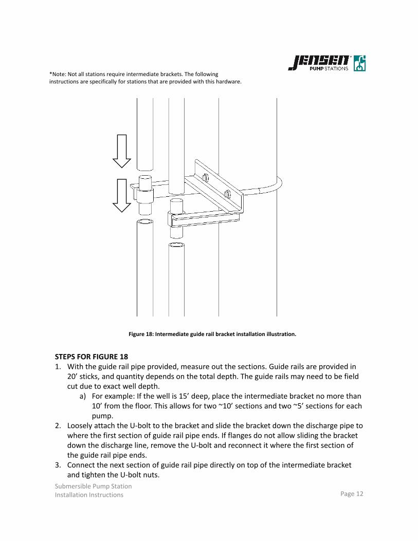
Figure 18: Intermediate guide rail bracket installation illustration.
STEPS FOR FIGURE 181. With the guide rail pipe provided, measure out the sections. Guide rails are provided in
20’ sticks, and quantity depends on the total depth. The guide rails may need to be field cut due to exact well depth.
a) For example: If the well is 15’ deep, place the intermediate bracket no more than 10’ from the floor. This allows for two ~10’ sections and two ~5’ sections for each pump.
2. Loosely attach the U‐bolt to the bracket and slide the bracket down the discharge pipe to where the first section of guide rail pipe ends. If flanges do not allow sliding the bracket down the discharge line, remove the U‐bolt and reconnect it where the first section of the guide rail pipe ends.
3. Connect the next section of guide rail pipe directly on top of the intermediate bracket and tighten the U‐bolt nuts.
*Note: Not all stations require intermediate brackets. The following instructions are specifically for stations that are provided with this hardware.

Submersible Pump StationInstallation Instructions Page 13
STEPS FOR FIGURE 20
1. Loosely install the U‐bolts on the discharge pipes and extend the bracket tubing on each side to reach the inner walls of the well.
2. Drill hole for wedge anchors with Roto‐Hammer.
a) WARNING: Take care to not drill all the way through the wall.
3. Install wedge anchors.
4. Place bracket angles on each side.
5. Tighten wedge anchor hex heads, tighten U‐bolt hex heads.
Figure 19: Typical pipe bracket by Placer Waterworks Inc.
Figure 20: Shown above is an example of the pipe bracket installation, with a close up of the wedge anchor placement.
*Note: Not all stations require pipe bracing. The following instructions are specifically for stations that are provided with this hardware.

Submersible Pump StationInstallation Instructions Page 14
STEPS FOR FIGURE 211. Lower pumps down guide rails onto
base elbows.a) Lifting chain with shackles are
supplied with the pump station materials.
2. The weight of the pumps creates a water tight seal to the base elbow.a) There is a gasket between the
guide claw and base elbow.3. THERE IS NO BOLTING REQUIRED to
connect pumps to the base elbows.
Note: The hoist shown on this page is not always included. Use the proper lifting equipment to lower the pumps into the well and to raise the pumps out of the well.
Figure 21: Pump is lowered onto base elbow via guide rails.
Figure 22: Pump is lowered onto base elbow via guide rails.
*Double doorhatch orientation– see page 3*

Submersible Pump StationInstallation Instructions Page 15
Figure 23: The above illustration is an example of electrical cable management.
ELECTRICAL CABLE MANAGEMENT NOTES
• It is essential to utilize proper cord separation techniques when hanging electrical cables.
• The electrical contractor is responsible for conduit installation. Jensen Pump Stations recommends 2” minimum conduit for both high and low voltage.
• Pumps typically have two cables exiting the casing. Refer to the installation instructions provided by the pump manufacturer to identify the low voltage and high voltage cables (typically, the high voltage cables have a larger diameter).
• All low voltage and high voltage cords MUST be ran in separate conduits to the control panel.
• If low voltage and high voltage cables are placed in the same conduit, a current can be induced in the low voltage cables and create false seal fail alarms.
See the following page for continued information.

Submersible Pump StationInstallation Instructions Page 16
CONTROL PANEL INSTALLATION NOTES
• The location and installation of the control panel is the responsibility of the installing contractor or electrical contractor.
• Jensen Pump Stations recommends that the panel is mounted as close to the wet well as possible to avoid voltage loss and make start up and continued maintenance more convenient.
• The panel enclosure may be mounted on a nearby wall or within a nearby structure.
• Please pull all cables to the control panel. If the control panel is too far to use factory connections, contact JPS (775‐440‐2025) for longer cables. If a junction box is ABSOLUTELY necessary, take note of Pressure Transducer Handling instructions on page 4. It is crucial that the junction box is completely watertight.
• See Appendix A for junction box installation recommendations.
• Leave all excess cable coiled within the control panel. A JPS pump technician will make the electrical connections at time of start‐up/commissioning.
Figure 24: Typical control panel installation.
UNISTRUT
RAIL
CONDUIT
PIPE

Submersible Pump StationInstallation Instructions Page 17
Please contact Jensen Pump Stations with any questions about the equipment, installation, or commissioning services.
(775) 440 ‐ 2025
• A completed pre‐commissioning check list (see Appendix B) is required in order to schedule start‐up and training services. Please send a copy of this form completed to [email protected] and call (775) 440 ‐ 2025 to schedule the date with one of our Pump Technicians. Please allow us 2 weeks’ notice to plan the commissioning of the station.

Submersible Pump StationInstallation Instructions Page 18
APPENDIX A

TYPICAL SYSTEM LAYOUT
NOT TO SCALE
PLAN SECTION
NOT TO SCALE
SECTION B-B
NOT TO SCALE
ISOMETRIC VIEW W/ COVER REMOVED
NOT TO SCALE
B
B
C C
PUMP
STATIONS
521 Dunn Circle, Sparks, NV 89431
JensenPumps.com
(855) 468-5600
Copyright Information ©2011 Jensen
Precast All Rights Reserved. All
materials appearing as Jensen Precast
documents and the like are propriety
work product and are protected under
U.S. copyright and other laws. Unless
in conjunction with business conducted
with Jensen Precast, any use of
Jensen Precast work product without
express, written consent is prohibited
and recipient is prohibited from
distributing any and all work product to
non-approved third parties under
penalty of civil action.
PROJECT:
TRAFFIC RATED JUNCTION BOX
STANDARD DETAIL
C:\Vault\Jobs\Standard Details\Installation Procedures\Junction Box\JENSEN JUNCTION.iam
DATE: DRAWN BY: SHEET NO:
MARCH 2016 NEC2 of 2
2"
2.5' MIN
2" PVC SCH40
CHECK VALVE
2" PVC SCH40
DRAIN LINE
PUMP STATION MANHOLE
ELECTRICAL
CONDUIT DESIGN
AND MATERIAL
BY OTHERS
SEAL CONDUIT WITH DOTTIES
DUCT SEAL PUTTY OR EQUAL
PRODUCT (SEWER APPLICATIONS
REQUIRE GAS TIGHT CONDUIT SEAL)
1" UNISTRUT RAIL SUPPORT
FOR JUNCTION BOXES
DRAIN ROCK DESIGN AND
COMPACTION BY OTHERS
LOW VOLTAGE NEMA
4X ELECTRICAL
JUNCTION BOX
HIGH VOLTAGE NEMA
4X ELECTRICAL
JUNCTION BOX
RIM/FINISH GRADE
PUMP HIGH VOLTAGE CONDUIT
(1.5" MINIMUM DIAMETER)
PUMP LOW VOLTAGE CONDUIT
(1.5" MINIMUM DIAMETER)
LEVEL SENSOR CONDUIT
(1.5" MINIMUM DIAMETER)
JENSEN PRECAST
HT1730 TRAFFIC BOX
1'-5"
2'-6"
TO CONTROL PANEL
1'-0" TYP.
3" TYP.
LOW VOLTAGE NEMA
4X ELECTRICAL
JUNCTION BOX
Jensen Pump Stations does not make
any claim that this detail is compliant
with the NEC or any other
jurisdictional electrical codes or
regulations.

Submersible Pump StationInstallation Instructions Page 19
APPENDIX B

521 Dunn Circle Sparks, NV 89431 (855)468-5600
PRE-COMMISSIONING CHECK LIST Please complete prior to scheduling a Jensen Engineered Systems representative for commissioning services.
DATE REQUESTED FOR STATION COMMISSIONING:
TODAY’S DATE:
PROJECT ADDRESS:
REQUESTED BY: Name:
Phone #:
Cell Phone #:
Company:
PROJECT NAME:
NUMBER OF STATIONS REQUIRING COMMISSIONING:
GENERAL
Has all mechanical equipment been installed? □ Yes or □ No
Is there an acceptable water source available for commissioning? □ Yes or □ No *Acceptable water source is a water truck or fire hose connection w/ hose. Garden hose is not acceptable.
Will a lifting device to remove pumps be available during commissioning? □ Yes or □ No
Have the wet well and all piping been cleared of debris? □ Yes or □ No
Has any of the equipment been exposed to sewage? □ Yes or □ No
Have appropriate parties been scheduled for training immediately following commissioning? □ Yes or □ No
ELECTRICAL
Is high voltage/low voltage wires in separate conduit? □ Yes or □ No
Has electrical conduit been sealed? □ Yes or □ No
Have the electrical leads for the pumps been landed in control panel? □ Yes or □ No
Have the leads for the level detection devices been landed in control panel? □ Yes or □ No
Has power been provided to the control panel? □ Yes or □ No
Is there a main disconnect panel prior to the pump station panel ? □ Yes or □ No
Is a junction box used? □ Yes or □ No
Verify in line voltage ______________________ L1/L2 = ________ L2/L3 = ________ L1/L3 = ________

521 Dunn Circle Sparks, NV 89431 (855)468-5600 STATION DESIGNATION:
*If there are multiple stations on a single job, submit a copy of this sheet for each station.
PUMPS
PUMP # 1 PUMP #1
PUMP #2 PUMP #2
PUMP #3
Select One: □ DUPLEX PUMP STATION □ TRIPLEX PUMP STATION
Refer to tag information on the side of the pump to collect the following information:
Pump # Serial Number Model Number
1
2
3
PHOTOS
Photos are very helpful for the Jensen Engineered Systems technician to review prior to visiting the project site for commissioning. If time permits, please submit pictures showing the overall site, the control panel with door open, and the inside of the wet well. Photos can be emailed to [email protected] (please put the project name in the subject line).