Improvement of Thermal Dissipation by Nanomaterial addition
35
Improvement of Thermal Dissipation by Nanomaterial addition B. Perez, R. Rodriguez , S. Florez, and C. Jimenez
Transcript of Improvement of Thermal Dissipation by Nanomaterial addition
Improvement
of Thermal
Dissipation
by Nanomaterial addition
B. Perez, R. Rodriguez, S. Florez, and
C. Jimenez
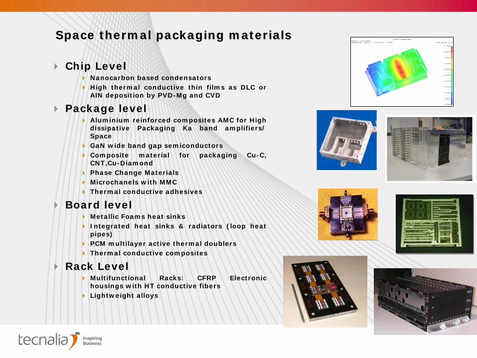
Chip Level
Nanocarbon based condensators
High thermal conductive thin films as DLC or AlN deposition by PVD-Mg and CVD
Package level
Aluminium reinforced composites AMC for High dissipative Packaging Ka band amplifiers/ Space
GaN wide band gap semiconductors
Composite material for packaging Cu-C, CNT,Cu-Diamond
Phase Change Materials
Microchanels with MMC
Thermal conductive adhesives
Board level
Metallic Foams heat sinks
Integrated heat sinks & radiators (loop heat pipes)
PCM multilayer active thermal doublers
Thermal conductive composites
Rack Level
Multifunctional Racks: CFRP Electroni c housings with HT conductive fibers
Lightweight alloys
SpaceSpace thermalthermal packagingpackaging materialsmaterials
ELECTRONIC INDUSTRY REQUIREMENTSELECTRONIC INDUSTRY REQUIREMENTS
Increase of power/packaging density
Miniaturization: Need for a continuous miniaturization of electronic devices
HEAT DISSIPATION
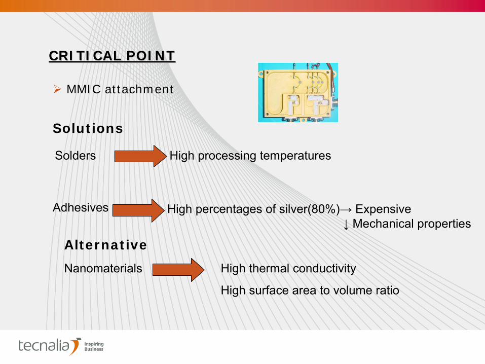
Solutions
Solders High
processing
temperatures
Adhesives High
percentages
of
silver(80%)→ Expensive↓
Mechanical
properties
MMIC attachment
CRITICAL POINTCRITICAL POINT
Alternative
Nanomaterials High
thermal
conductivity
High
surface
area
to
volume
ratio
The aim of this study was to conduct research in
nanomaterials to be used to dope adhesives for space
conditions in order to increase their thermal
conductivity.
MaterialsMaterials
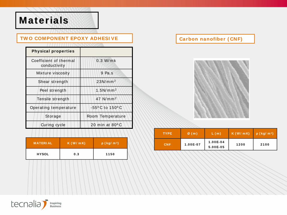
TYPE Ø (m) L (m) K (W/mK) ρ
(kg/m3)
CNF 1.00E-071.00E-04
5.00E-051200 2100
Carbon nanofiber (CNF)TWO COMPONENT EPOXY ADHESIVE
MATERIAL K (W/mK) ρ
(kg/m3)
HYSOL 0.3 1150
Physical properties
Coefficient of thermal conductivity
0.3 W/mk
Mixture viscosity 9 Pa.s
Shear strength 23N/mm2
Peel strength 1.5N/mm2
Tensile strength 47 N/mm2
Operating temperature -55ºC to 150ºC
Storage Room Temperature
Curing cycle 20 min at 80ºC
ADHESIVE
q ELECTRONIC BOARD
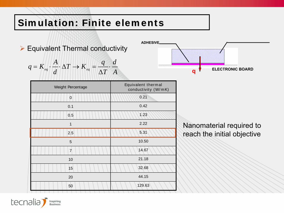
SimulationSimulation: : FiniteFinite elementselements
Ad
TqKT
dAKq eqeq
Equivalent
Thermal
conductivity
Weight Percentage Equivalent thermal conductivity (W/mK)
0 0.21
0.1 0.42
0.5 1.23
1 2.22
2.5 5.31
5 10.50
7 14.67
10 21.18
15 32.68
20 44.15
50 129.63
Nanomaterial
required to reach the initial objective
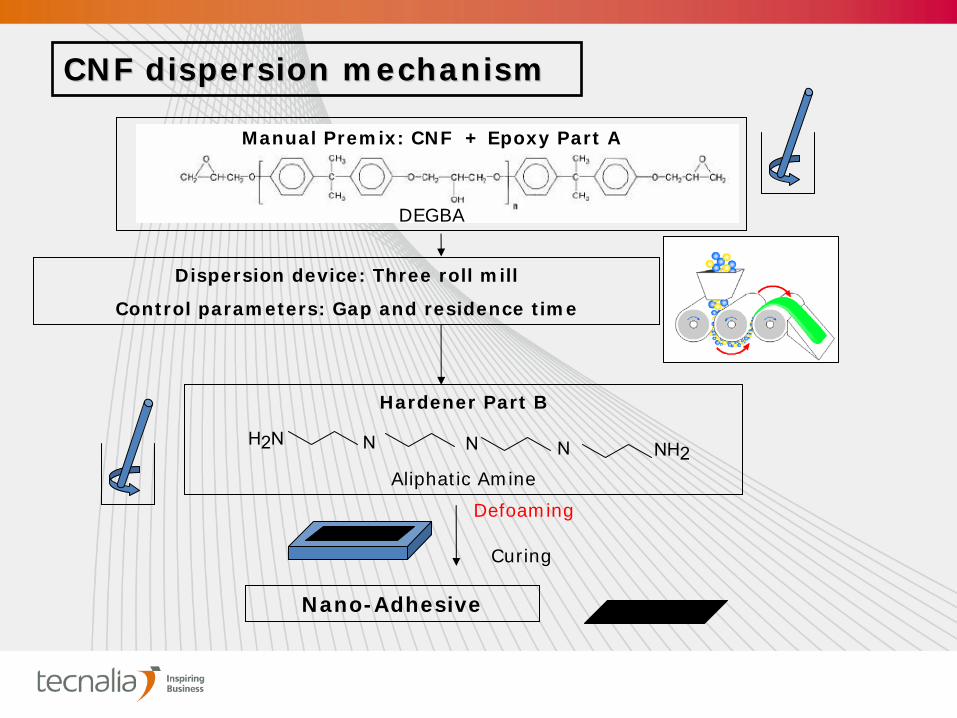
CNF dispersion mechanismCNF dispersion mechanism
Manual Premix: CNF + Epoxy Part A
DEGBA
Dispersion device: Three roll mill
Control parameters: Gap and residence time
Defoaming
Hardener Part B
Aliphatic Amine
H2N N NN NH2
Nano-Adhesive
Curing
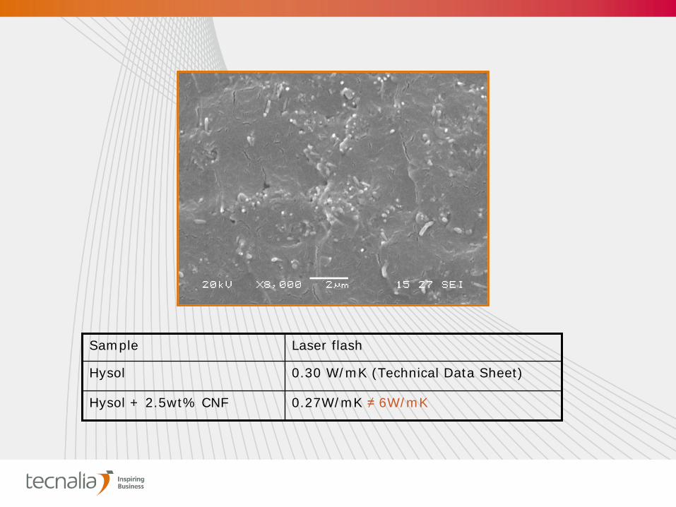
Sample Laser flash
Hysol 0.30 W/mK (Technical Data Sheet)
Hysol + 2.5wt% CNF 0.27W/mK ≠
6W/mK
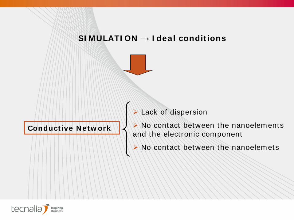
Lack of dispersion
No contact between the nanoelements and the electronic component
No contact between the nanoelemets
SIMULATION →
Ideal conditions
Conductive Network
Strategies to improve thermal conductivityStrategies to improve thermal conductivity
Heat treated CNF effect (1h at 2800ºC under He
atmosphere)
Synergetic effect between two nanomaterials with
different size and shape
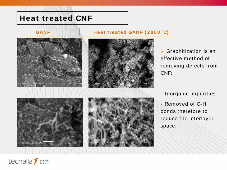
GANF Heat treated GANF (2800ºC)
Heat treated CNFHeat treated CNF
Graphitization is an effective method of removing defects from CNF:
- Inorganic impurities
- Removed of C-H bonds therefore to reduce the interlayer space.
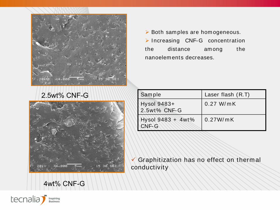
2.5wt% CNF-G
4wt% CNF-G
Both samples are homogeneous.
Increasing CNF-G concentration
the distance among the
nanoelements decreases.
Sample Laser flash (R.T)
Hysol 9483+ 2.5wt% CNF-G
0.27 W/mK
Hysol 9483 + 4wt% CNF-G
0.27W/mK
Graphitization has no effect on thermal conductivity
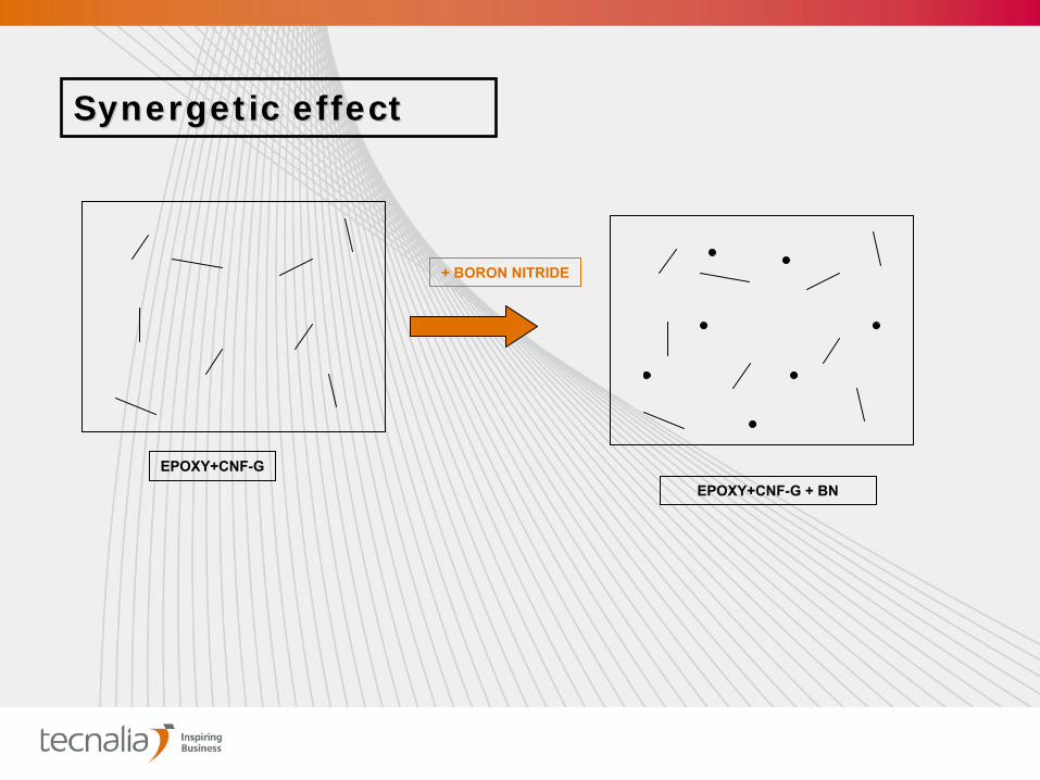
Synergetic effectSynergetic effect
EPOXY+CNF-GEPOXY+CNF-G + BN
+ BORON NITRIDE

MaterialsMaterialsNANOMATERIAL
- Boron nitride (BN)
Boron Nitride, cubic
Particle size full range: 80-450 nm
Average particle size: 165±15 nm
Specific surface: > 11 m2/g
Content of cubic phase: > 99,0 w.%
Thermal conductivity: 600W/mk
Density: 3,45 g/cm3
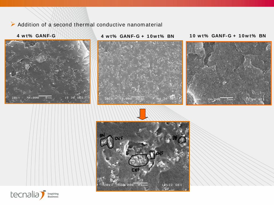
4 wt% GANF-G + 10wt% BN4 wt% GANF-G
Addition of a second thermal conductive nanomaterial
10 wt% GANF-G + 10wt% BN

Sample Laser Flash (W/mK)
Heat treated CNF 4wt%
0.27
Heat treated CNF 4wt%+ BN 10wt%
0.23
Heat treated CNF 10wt% + BN 10wt%
0.23
Heat treated CNF 20wt%*
-
ThermalThermal Conductivity MeasurementsConductivity Measurements
*Too viscous
system
0
0,2
0,4
0,6
0,8
1
0 10 20 30 40 50 60
K (W
/mK)
% BN
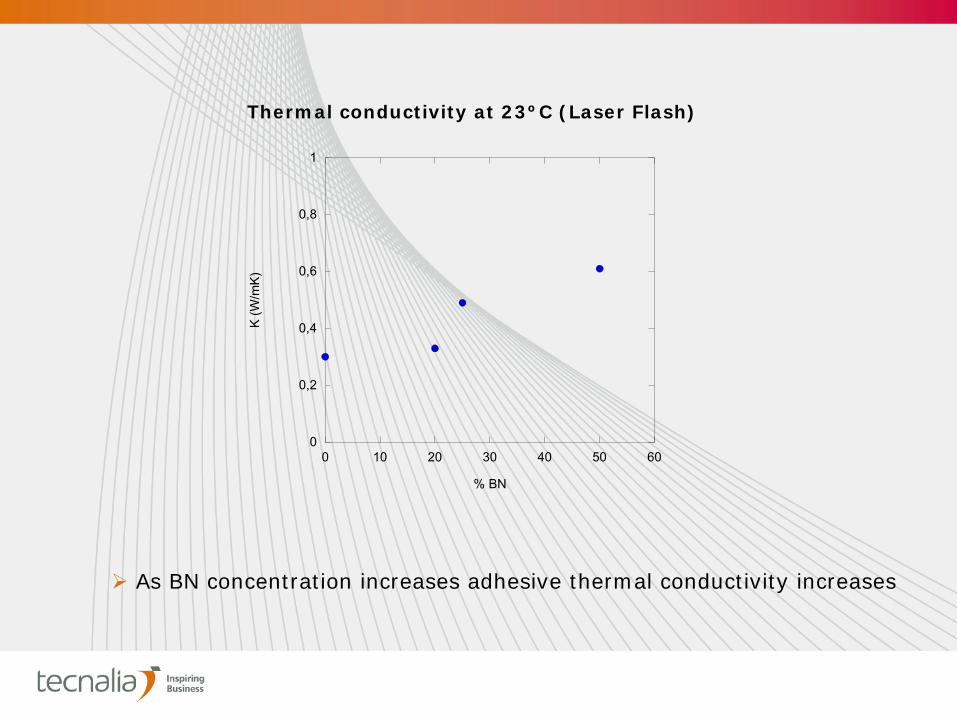
As BN concentration increases adhesive thermal conductivity increases
Thermal conductivity at 23ºC (Laser Flash)
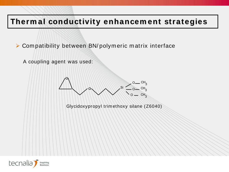
Thermal conductivity enhancement strategiesThermal conductivity enhancement strategies
Compatibility between BN/polymeric matrix interface
Glycidoxypropyl trimethoxy silane (Z6040)
o
o SiO CH3
CH3CH3
O
O
A coupling agent was used:
H
H
H
O
O
OSio
o
o
o SiO
O
O
H
H
H
HO
HO
O
O
OSio
o
H2O
PH=4.5
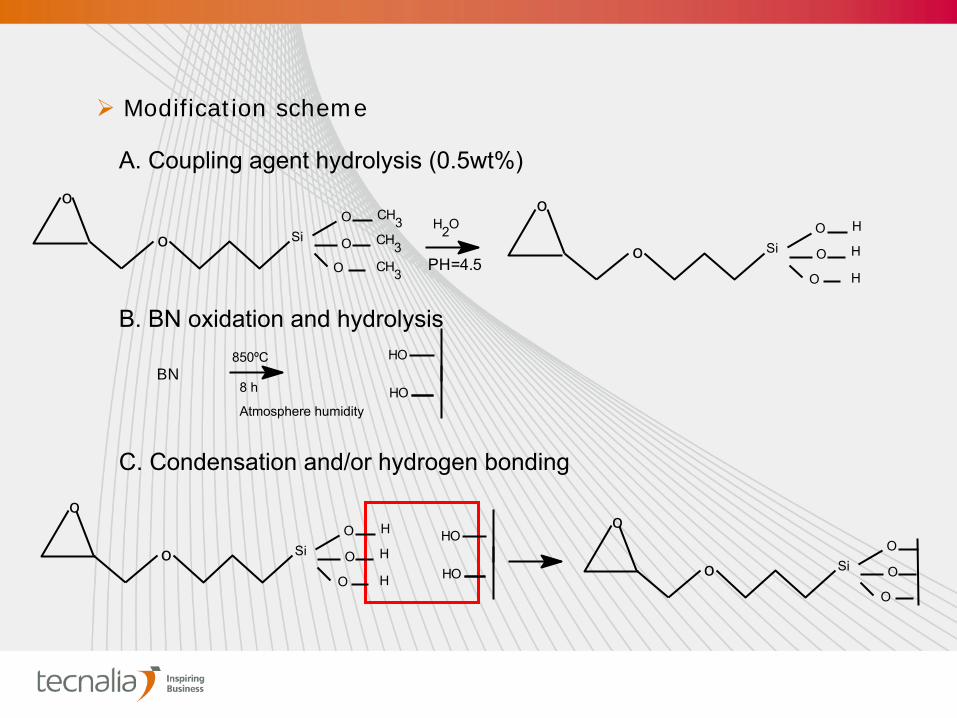
Modification scheme
o
o SiO CH3
CH3CH3
O
O
A. Coupling agent hydrolysis (0.5wt%)
B. BN oxidation and hydrolysis
BN850ºC
8 h
Atmosphere humidity
C. Condensation and/or hydrogen bonding
HO
HO
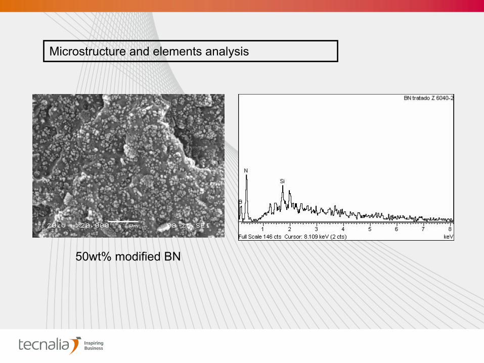
50wt% modified
BN
Microstructure
and
elements
analysis
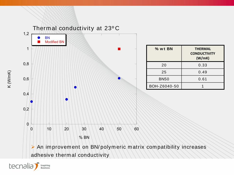
An improvement on BN/polymeric matrix compatibility increases
adhesive thermal conductivity
%wt BN THERMAL
CONDUCTIVITY
(W/mK)
20 0.33
25 0.49
BN50 0.61
BOH-Z6040-50 1
Thermal conductivity at 23ºC
0
0,2
0,4
0,6
0,8
1
1,2
0 10 20 30 40 50 60
BNModified BN
K (W
/mK)
% BN
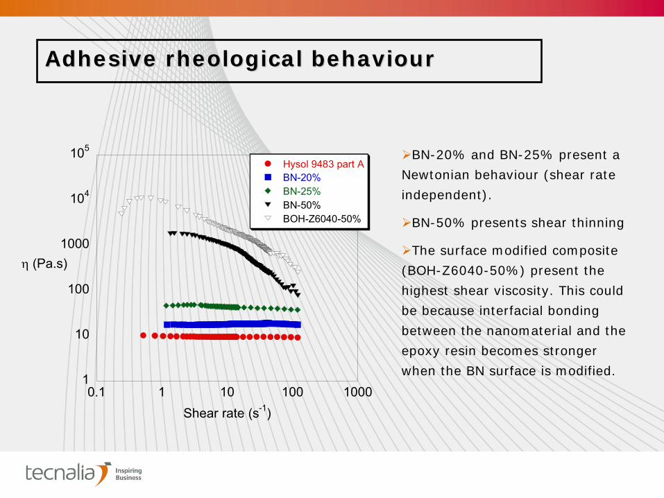
Adhesive rheological Adhesive rheological behaviourbehaviour
1
10
100
1000
104
105
0.1 1 10 100 1000
Hysol 9483 part ABN-20%BN-25%BN-50%BOH-Z6040-50%
(Pa.s)
Shear rate (s-1)
BN-20% and BN-25% present a
Newtonian behaviour (shear rate
independent).
BN-50% presents shear thinning
The surface modified composite
(BOH-Z6040-50%) present the
highest shear viscosity. This could
be because interfacial bonding
between the nanomaterial and the
epoxy resin becomes stronger
when the BN surface is modified.
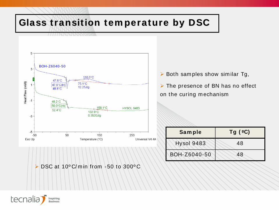
Glass transition temperature by DSCGlass transition temperature by DSC
BOH-Z6040-50
DSC at 10ºC/min from -50 to 300ºC
Both samples show similar Tg,
The presence of BN has no effect
on the curing mechanism
Sample Tg (ºC)
Hysol 9483 48
BOH-Z6040-50 48
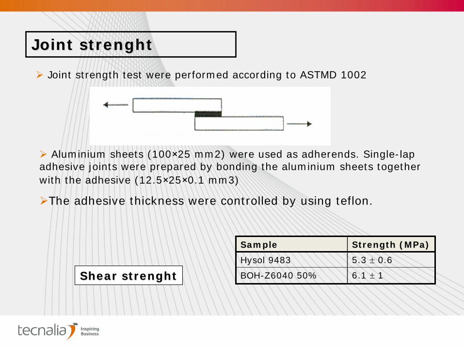
Joint Joint strenghtstrenght
Joint strength test were performed according to ASTMD 1002
Aluminium sheets (100×25 mm2) were used as adherends. Single-lap adhesive joints were prepared by bonding the aluminium sheets together with the adhesive (12.5×25×0.1 mm3)
The adhesive thickness were controlled by using teflon.
Sample Strength (MPa)
Hysol 9483 5.3
0.6
BOH-Z6040 50% 6.1
1Shear Shear strenghtstrenght
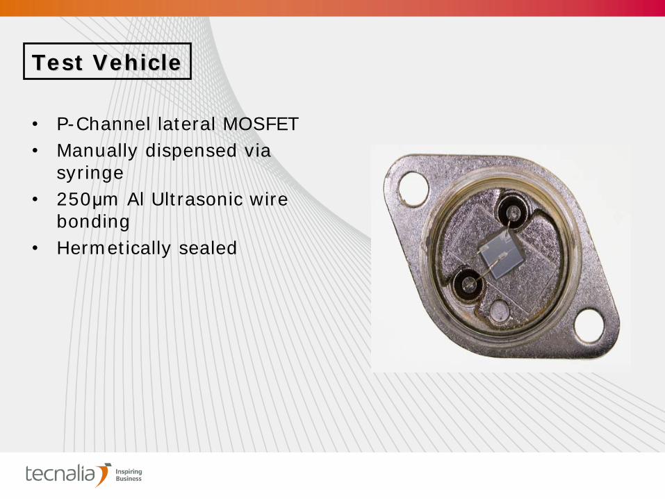
•
P-Channel lateral MOSFET •
Manually dispensed via syringe
•
250μm Al Ultrasonic wire bonding
•
Hermetically sealed
Test VehicleTest Vehicle
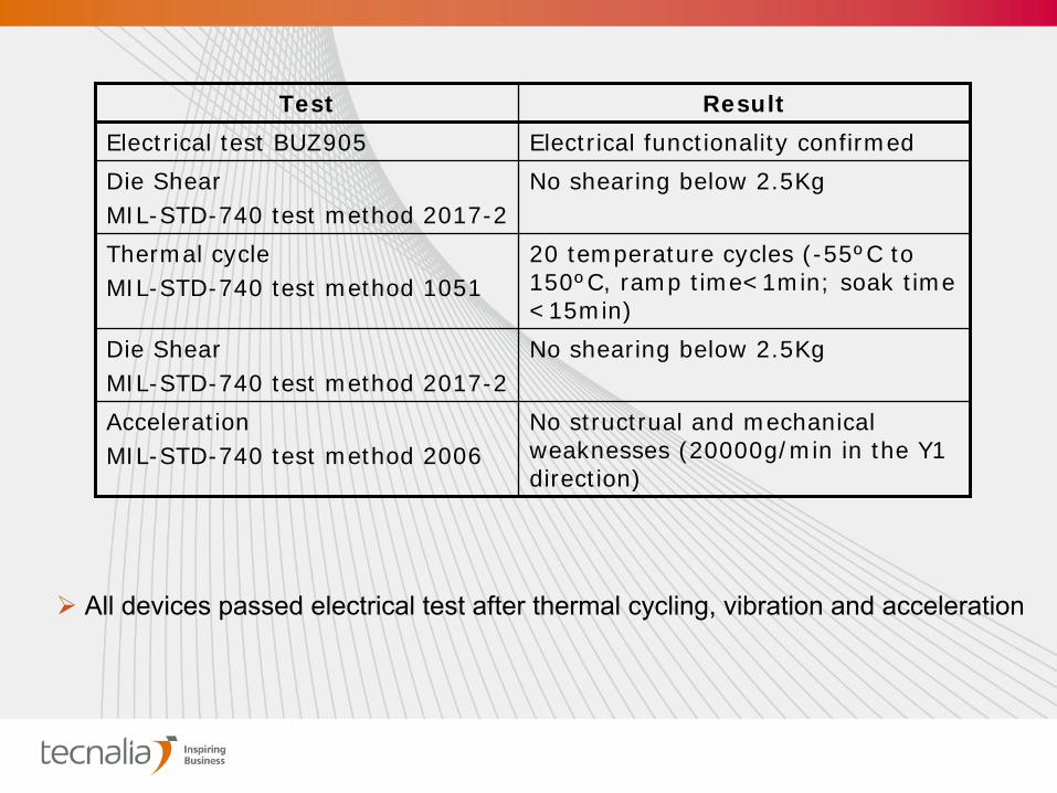
Test Result
Electrical test BUZ905 Electrical functionality confirmed
Die ShearMIL-STD-740 test method 2017-2
No shearing below 2.5Kg
Thermal cycleMIL-STD-740 test method 1051
20 temperature cycles (-55ºC to 150ºC, ramp time<1min; soak time <15min)
Die ShearMIL-STD-740 test method 2017-2
No shearing below 2.5Kg
AccelerationMIL-STD-740 test method 2006
No structrual and mechanical weaknesses (20000g/min in the Y1 direction)
All
devices
passed
electrical
test after
thermal
cycling, vibration
and
acceleration

ThermalThermal impedanceimpedance MILMIL--STSSTS--750 Test 750 Test methodmethod 3161.13161.1
Lead
tin
solder: 0.8ºC/W
Comercial epoxy
silver
loaded: 7ºC/W
Nanoadhesive: 16.8ºC/W
R=1/KL/A
Comercial epoxy
silver
loaded: 2.5W/mK
Nanoadhesive: 0.96W/mK
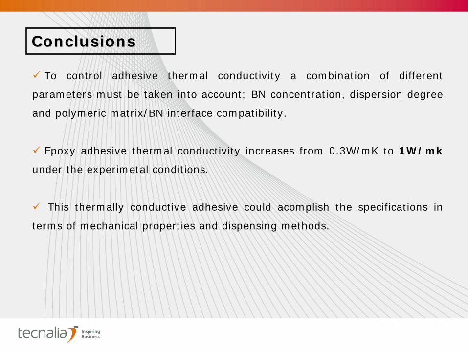
ConclusionsConclusions
To control adhesive thermal conductivity a combination of different
parameters must be taken into account; BN concentration, dispersion degree
and polymeric matrix/BN interface compatibility.
Epoxy adhesive thermal conductivity increases from 0.3W/mK to 1W/mk
under the experimetal conditions.
This thermally conductive adhesive could acomplish the specifications in
terms of mechanical properties and dispensing methods.

ESA Contract
No. 20333/06/F/VS
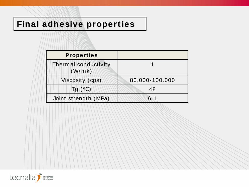
Final adhesive propertiesFinal adhesive properties
Properties
Thermal conductivity (W/mk)
1
Viscosity (cps) 80.000-100.000
Tg (ºC) 48
Joint strength (MPa) 6.1
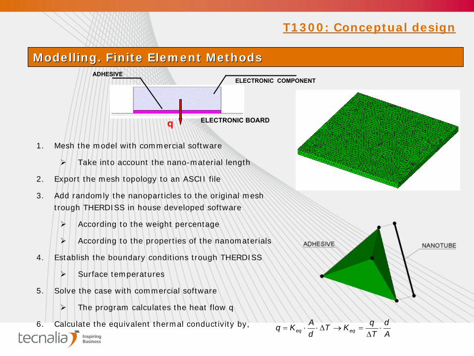
1. Mesh the model with commercial software
Take into account the nano-material length
2. Export the mesh topology to an ASCII file
3. Add randomly the nanoparticles to the original mesh trough THERDISS in house developed software
According to the weight percentage
According to the properties of the nanomaterials
4. Establish the boundary conditions trough THERDISS
Surface temperatures
5. Solve the case with commercial software
The program calculates the heat flow q
6. Calculate the equivalent thermal conductivity by,Ad
TqKT
dAKq eqeq
Modelling. Finite Element MethodsModelling. Finite Element Methods
T1300: Conceptual design
ELECTRONIC COMPONENTADHESIVE
q ELECTRONIC BOARD
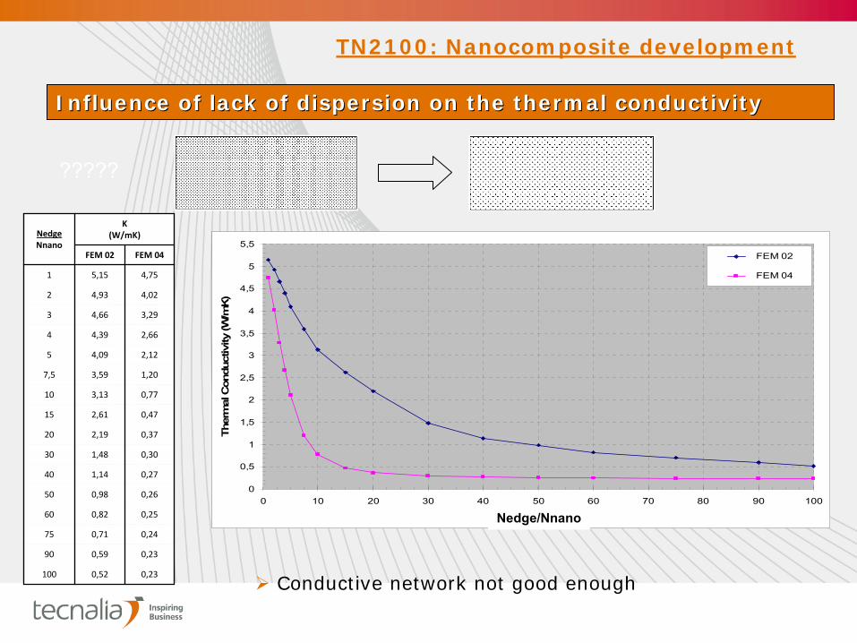
Influence of lack of dispersion on the thermal conductivityInfluence of lack of dispersion on the thermal conductivity
NedgeNnano
K(W/mK)
FEM 02 FEM 04
1 5,15 4,75
2 4,93 4,02
3 4,66 3,29
4 4,39 2,66
5 4,09 2,12
7,5 3,59 1,20
10 3,13 0,77
15 2,61 0,47
20 2,19 0,37
30 1,48 0,30
40 1,14 0,27
50 0,98 0,26
60 0,82 0,25
75 0,71 0,24
90 0,59 0,23
100 0,52 0,23
0
0,5
1
1,5
2
2,5
3
3,5
4
4,5
5
5,5
0 10 20 30 40 50 60 70 80 90 100
NARIST / NNANO
Ther
mal
Con
duct
ivity
(W/m
K)
FEM 02
FEM 04
Nedge/Nnano
TN2100: Nanocomposite development
Conductive network not good enough
?????
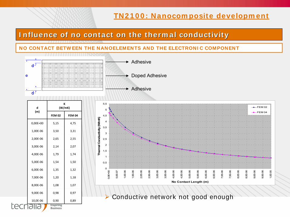
Influence of no contact on the thermal conductivityInfluence of no contact on the thermal conductivity
NO CONTACT BETWEEN THE NANOELEMENTS AND THE ELECTRONIC COMPONENT
0
0,5
1
1,5
2
2,5
3
3,5
4
4,5
5
5,5
0,0E
+00
5,0E
-07
1,0E
-06
1,5E
-06
2,0E
-06
2,5E
-06
3,0E
-06
3,5E
-06
4,0E
-06
4,5E
-06
5,0E
-06
5,5E
-06
6,0E
-06
6,5E
-06
7,0E
-06
7,5E
-06
8,0E
-06
8,5E
-06
9,0E
-06
9,5E
-06
1,0E
-05
No Contact Length (m)
Ther
mal
Con
duct
ivity
(W/m
K)
FEM 02
FEM 04
d(m)
K(W/mK)
FEM 02 FEM 04
0,00E+00 5,15 4,75
1,00E‐06 3,50 3,31
2,00E‐06 2,65 2,55
3,00E‐06 2,14 2,07
4,00E‐06 1,79 1,74
5,00E‐06 1,54 1,50
6,00E‐06 1,35 1,32
7,00E‐06 1,20 1,18
8,00E‐06 1,08 1,07
9,00E‐06 0,98 0,97
10,0E‐06 0,90 0,89
Adhesive
Doped Adhesive
Adhesive
TN2100: Nanocomposite development
Conductive network not good enough
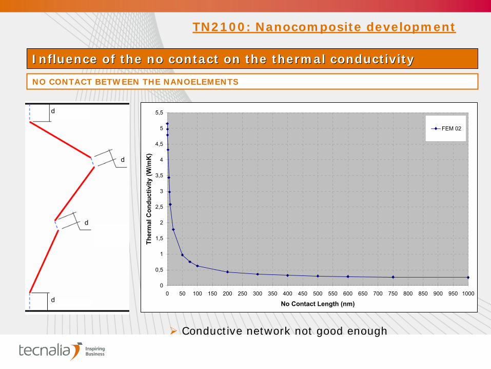
Influence of the no contact on the thermal conductivityInfluence of the no contact on the thermal conductivity
NO CONTACT BETWEEN THE NANOELEMENTS
0
0,5
1
1,5
2
2,5
3
3,5
4
4,5
5
5,5
0 50 100 150 200 250 300 350 400 450 500 550 600 650 700 750 800 850 900 950 1000
No Contact Length (nm)
Ther
mal
Con
duct
ivity
(W/m
K)
FEM 02
d
d
d
d
TN2100: Nanocomposite development
Conductive network not good enough