Im Electricalwiring 021209
16
IMPORTANT! DO NOT DESTROY ¡IMPORTANTE! NO DESTRUIR A ssem b l y Instructions A nd Electrical Wiring Diagrams Installer HYTROL CONVEYOR CO., INC. © COPYRIGHT 2009–HYTROL CONVEYOR CO., INC. Jonesboro, Arkansas Effective February 2009 (Supercedes January 2005) Bulletin #615 Instrucciones d e Ensam b l e y Diagramas de Conexión Eléctrica Instalador
-
Upload
donald-harris -
Category
Documents
-
view
217 -
download
0
Transcript of Im Electricalwiring 021209
8/13/2019 Im Electricalwiring 021209
http://slidepdf.com/reader/full/im-electricalwiring-021209 1/16
IMPORTANT!DO NOT DESTROY
¡IMPORTANTE! NO DESTRUIR
AssemblyInstructions
AndElectrical
WiringDiagrams
Installer
HYTROL CONVEYOR CO., INC.© COPYRIGHT 2009–HYTROL CONVEYOR CO., INC.
Jonesboro, Arkansas
Effective February 2009(Supercedes January 2005)
Bulletin #615
Instruccionesde Ensambley Diagramas
de ConexiónEléctrica
Instalador
8/13/2019 Im Electricalwiring 021209
http://slidepdf.com/reader/full/im-electricalwiring-021209 2/16
Electrical Wiring Diagrams
CONTROLS: PAGE
Reversing Drum Switch . . . . . . . . . . . . . . . . . . . . . . . . . . . . . . . . . . . . . . . . . . . . . . 3
Safety Disconnect Switch or Manual Start Switch . . . . . . . . . . . . . . . . . . . . . . . . . . 4
Push Button Station . . . . . . . . . . . . . . . . . . . . . . . . . . . . . . . . . . . . . . . . . . . . . . . . . 5
Reversing Three Phase Starter . . . . . . . . . . . . . . . . . . . . . . . . . . . . . . . . . . . . . . . . 6
Non-Reversing Three Phase Starter . . . . . . . . . . . . . . . . . . . . . . . . . . . . . . . . . . . . 7
Reversing Single Phase Magnetic Starter (115 Volt). . . . . . . . . . . . . . . . . . . . . . . . 8
Reversing Single Phase Magnetic Starter (230 Volt). . . . . . . . . . . . . . . . . . . . . . . . 9
Non-Reversing Single Phase Magnetic Starter (115 Volt). . . . . . . . . . . . . . . . . . . 10
Non-Reversing Single Phase Magnetic Starter (230 Volt). . . . . . . . . . . . . . . . . . . 11
MOTOR:
Motor Wiring Diagram Single Phase 115/230 Volt. . . . . . . . . . . . . . . . . . . . . . . . . 12
Motor Wiring Diagram Three Phase Single Voltage Motors . . . . . . . . . . . . . . . . . 13
Motor Wiring Diagram Three Phase Dual Voltage Motors. . . . . . . . . . . . . . . . . . . 13
Variable Speed Drive:
VS1 MD Drive. . . . . . . . . . . . . . . . . . . . . . . . . . . . . . . . . . . . . . . . . . . . . . . . . . . . . . . .14
VS1 MX Drive. . . . . . . . . . . . . . . . . . . . . . . . . . . . . . . . . . . . . . . . . . . . . . . . . . . . . . . .15
2
(Interruptor Reversible de Tambor)
(Controles:) (Página)
(Interruptor Desconector de Seguridad o Interruptor Manual de Encendido)
(Estación de Botones)
(Arrancador Trifásico Reversible)
(Arrancador Trifásico Irreversible)
(Arrancador Magnético Monofásico Reversible (115 Voltios))
(Arrancador Magnético Monofásico Reversible (230 Voltios))
(Arrancador Magnético Monofásico Irreversible (115 Voltios))
(Arrancador Magnético Monofásico Irreversible (230 Voltios))
(Diagrama de conexión de motor monofásico 115/230 Voltios)
(Diagrama de conexión de motor trifásico de voltaje sencillo)
(Diagrama de conexión de motor trifásico de doble voltaje)
(Diagrama de conexión de motor trifásico de doble voltaje:)
(Diagramas de Conexión Eléctrica)
(Unidad Motriz VS1 MX)
(Unidad Motriz VS1 MD)
8/13/2019 Im Electricalwiring 021209
http://slidepdf.com/reader/full/im-electricalwiring-021209 3/16
FWD REVOFF
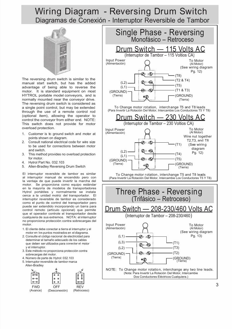
Wiring Diagram - Reversing Drum Switch
To Motor
To Motor
To Motor
The reversing drum switch is similar to the
manual start switch, but has the added
advantage of being able to reverse the
motor. It is standard equipment on most
HYTROL portable model conveyors, and is
normally mounted near the conveyor drive.
The reversing drum switch is considered as
a single point control, but may be extended
through the use of a remote control rod
(optional item), allowing the operator tocontrol the conveyor from either end. NOTE:
This switch does not provide for motor
overload protection.
To Change motor rotation, interchange T5 and T8 leads
Input Power
Input Power
(L2)
(T8)
(T2 & T4)
(T1 & T3)
(GROUND)
(L1)
(GROUND)
1 2
3 4
5 6
Drum Switch — 115 Volts AC
Drum Switch — 230 Volts AC
Wire nut together
T2,T3, and T8
(See wiring
diagram
Pg. 12)
To Change motor rotation, interchange T5 and T8 leads
(L2)
(T1)
(T4)
(T5)
(GROUND)
(L1)
(GROUND)
1 2
3 4
5 6
1. Customer is to ground switch and motor at
points shown on diagram.
2. Consult national electrical code for wire size
to be used for connections between motor
and switch.
3. This method provides no overload protection
for motor.
4. Hytrol Part No. 032.103
5. Allen-Bradley Reversing Drum Switch
Input Power
NOTE: To Change motor rotation, interchange any two line leads.
(L3)
(L2)
(T2)
(T3)
(T1)
(GROUND)
(L1)
(GROUND)
1 2
3 4
5 6
Drum Switch — 208-230/460 Volts AC
3
Single Phase - Reversing
Three Phase - Reversing
(T5)
(See wiring diagram
Pg. 12)
(See wiring diagramPg. 13)
El interruptor reversible de tambor es similaral interruptor manual de encendido pero con
la ventaja de que puede invertir la marcha del
motor. Se proporciona como equipo estándar
en la mayoría de modelos de transportadores
Hytrol portátiles y normalmente se instala
cerca a la unidad motriz del transportador. El
interruptor reversible de tambor es considerado
como el punto de control del transportador pero
puede ser extendido incorporando un barra para
control remoto (artículo opcional) que permite
que el operador controle el transportador desde
cualquiera de sus extremos. NOTA: el interruptor
no proporciona protección contra sobrecargas del
motor.
1. El cliente debe conectar a tierra el interruptor y el motor en los puntos mostrados en el diagrama.2. Consulte el código nacional de electricidad para determinar el tamaño adecuado de los cables que deben ser utilizados para conectar el motor y el interruptor.3. Este método no proporciona protección contra sobrecargas del motor.4. Número de parte de Hytrol: 032.1035. Interruptor reversible de tambor marca Allen-Bradley
(Avance) (Desconexión) (Retroceso)
Monofásico – Retroceso
(Trifásico – Retroceso)
(Tierra)
(Alimentación) (Al Motor)
(Tierra)
(Para Invertir La Rotación Del Motor, Intercambie Los Conductores T5 Y T8)
(Nota: Para Invertir La Rotación Del Motor, IntercambieDos Conductores Eléctricos Cualquiera.)
(Interruptor de Tambor – 115 Voltios CA)
(Interruptor de Tambor – 208-230/460)
Diagramas de Conexión - Interruptor Reversible de Tambor
(Interruptor de Tambor – 230 Voltios CA)
(Alimentación) (Al Motor)
(Tierra)(Tierra)
(Para Invertir La Rotación Del Motor, Intercambie Los Conductores T5 Y T8)
(Alimentación) (Al Motor)
(Tierra)(Tierra)
8/13/2019 Im Electricalwiring 021209
http://slidepdf.com/reader/full/im-electricalwiring-021209 4/16
ONOFF
(GROUND)
(L1)
(L2)
(L3)
(GROUND)
(T1)
(T2)
(T3)LINE
LINE
LINE
LOAD
LOAD
LOAD
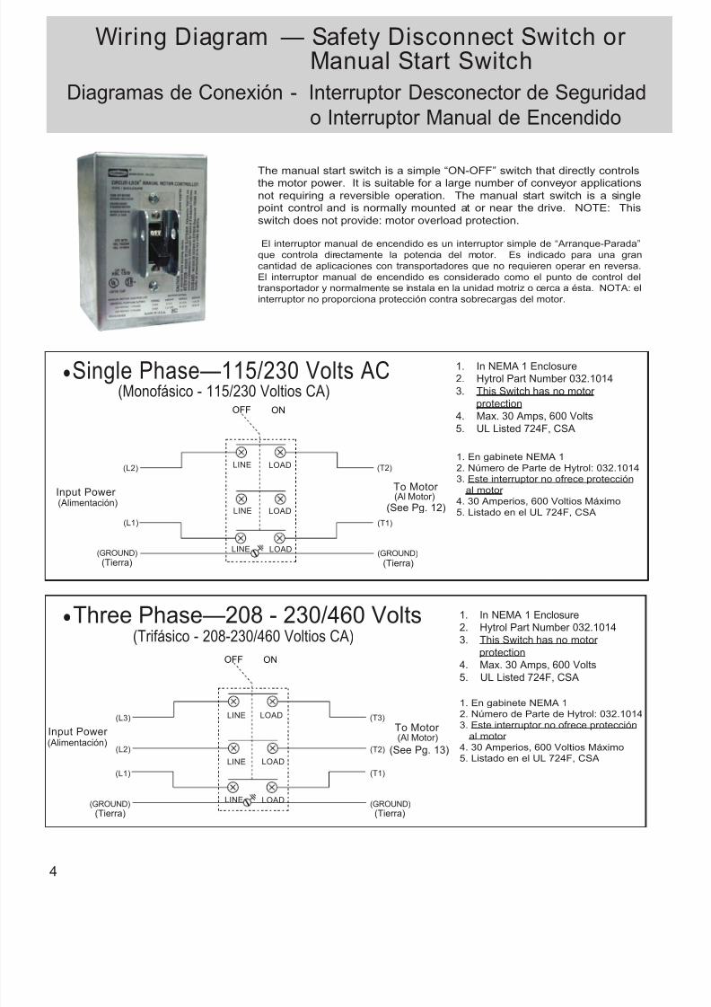
•Three Phase—208 - 230/460 Volts 1. In NEMA 1 Enclosure
2. Hytrol Part Number 032.1014
3. This Switch has no motor
protection
4. Max. 30 Amps, 600 Volts
5. UL Listed 724F, CSA
•Single Phase—115/230 Volts AC
The manual start switch is a simple “ON-OFF” switch that directly controls
the motor power. It is suitable for a large number of conveyor applications
not requiring a reversible operation. The manual start switch is a single
point control and is normally mounted at or near the drive. NOTE: This
switch does not provide: motor overload protection.
1. In NEMA 1 Enclosure
2. Hytrol Part Number 032.1014
3. This Switch has no motor
protection
4. Max. 30 Amps, 600 Volts
5. UL Listed 724F, CSA
OFF ON
(GROUND)
(L1)
(L2)
(GROUND)
(T1)
(T2)LINE
LINE
LOAD
LOAD
LINE LOAD
4
Wiring Diagram — Safety Disconnect Switch or Manual Start Switch
To Motor
To Motor
Input Power
Input Power
(See Pg. 12)
(See Pg. 13)
El interruptor manual de encendido es un interruptor simple de “Arranque-Parada”
que controla directamente la potencia del motor. Es indicado para una gran
cantidad de aplicaciones con transportadores que no requieren operar en reversa.
El interruptor manual de encendido es considerado como el punto de control del
transportador y normalmente se instala en la unidad motriz o cerca a ésta. NOTA: el
interruptor no proporciona protección contra sobrecargas del motor.
1. En gabinete NEMA 1
2. Número de Parte de Hytrol: 032.1014
3. Este interruptor no ofrece protección
al motor
4. 30 Amperios, 600 Voltios Máximo
5. Listado en el UL 724F, CSA
1. En gabinete NEMA 12. Número de Parte de Hytrol: 032.1014
3. Este interruptor no ofrece protección
al motor
4. 30 Amperios, 600 Voltios Máximo
5. Listado en el UL 724F, CSA
Diagramas de Conexión - Interruptor Desconector de Seguridado Interruptor Manual de Encendido
(Monofásico - 115/230 Voltios CA)
(Trifásico - 208-230/460 Voltios CA)
(Alimentación)(Al Motor)
(Tierra) (Tierra)
(Alimentación) (Al Motor)
(Tierra) (Tierra)
8/13/2019 Im Electricalwiring 021209
http://slidepdf.com/reader/full/im-electricalwiring-021209 5/16
FWD FWD
REV
STOP STOP
REV
A
B
C
D
FWD
REV
STOP
FWD
REV
FWD
REV
A
B
C
D
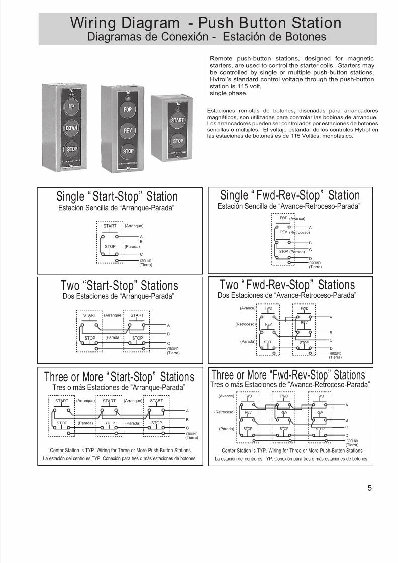
Single “ Start-Stop” Station
Two “Start-Stop” Stations
Three or More “ Start-Stop” Stations
Single “ Fwd-Rev-Stop” Station
Two “ Fwd-Rev-Stop” Stations
Three or More “Fwd-Rev-Stop” Stations
START
A
B
C
STOP
START
A
B
C
STOP STOP
START
START
A
B
C
GROUND
START START
Center Station is TYP. Wiring for Three or More Push-Button Stations
REV
STOP
FWD
A
B
C
D
STOP STOP STOP
Remote push-button stations, designed for magnetic
starters, are used to control the starter coils. Starters may
be controlled by single or multiple push-button stations
Hytrol’s standard control voltage through the push-button
station is 115 volt,
single phase.
GROUND
GROUND
GROUND
GROUND
GROUND
5
Wiring Diagram - Push Button Station
STOP
STOP
Estaciones remotas de botones, diseñadas para arrancadore
magnéticos, son utilizadas para controlar las bobinas de arranqu
Los arrancadores pueden ser controlados por estaciones de botone
sencillas o múltiples. El voltaje estándar de los controles Hytrol e
las estaciones de botones es de 115 Voltios, monofásico.
Estación Sencilla de “Arranque-Parada” Estación Sencilla de “Avance-Retroceso-Parada”
Dos Estaciones de “Arranque-Parada” Dos Estaciones de “Avance-Retroceso-Parada”
Tres o más Estaciones de “Avance-Retroceso-Parada”Tres o más Estaciones de “Arranque-Parada”
(Tierra)
Diagramas de Conexión - Estación de Botones
La estación del centro es TYP. Conexión para tres o más estaciones de botones
(Arranque)
(Parada)
(Retroceso)
(Avance)
(Parada)
Center Station is TYP. Wiring for Three or More Push-Button Stations
La estación del centro es TYP. Conexión para tres o más estaciones de botones
(Tierra)
(Arranque)
(Parada)
(Arranque)
(Parada)
(Arranque)
(Parada)
(Tierra)
(Tierra)
(Retroceso)
(Avance)
(Parada)
(Tierra)
(Retroceso)
(Avance)
(Parada)
(Tierra)
8/13/2019 Im Electricalwiring 021209
http://slidepdf.com/reader/full/im-electricalwiring-021209 6/16
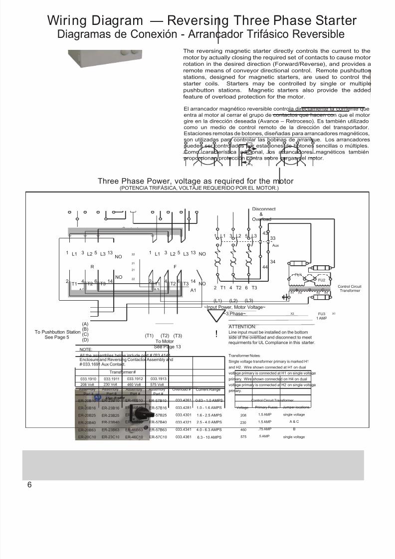
The reversing magnetic starter directly controls the current to the
motor by actually closing the required set of contacts to cause motor
rotation in the desired direction (Forward/Reverse), and provides a
remote means of conveyor directional control. Remote pushbutton
stations, designed for magnetic starters, are used to control the
starter coils. Starters may be controlled by single or multiple
pushbutton stations. Magnetic starters also provide the added
feature of overload protection for the motor.
3 5 13
1464
1
2T2 T3T1 NO
L1 L2 L3 NO
A1 A2 A2
L3L2L1
T1 T3T22
1
4 6 14
1353
FR
Contactors
A1
22
21
21
22NO
NO
(A)(B)(C)
(D)
To Pushbutton Station
ER-20B10
ER-20B16
ER-20B25
ER-20B63
ER-20B40
ER-20C10
ER-23B10
ER-23C10
ER-23B63
ER-23B40
ER-23B25
ER-23B16
ER-46C10
ER-46B63
ER-46B10
ER-46B16
ER-46B25
ER-46B40
ER-57C10
ER-57B63
ER-57B10
ER-57B16
ER-57B25
ER-57B40
033.4261
033.4281
033.4301
033.4321
033.4341
033.4361
Overload #
0.63 - 1.0 AMPS
1.0 - 1.6 AMPS
1.6 - 2.5 AMPS
2.5 - 4.0 AMPS
4.0 - 6.3 AMPS
6.3 - 10 AMPS
Current Range
Transformer #
Voltage
Control Circuit Transformer
208
230
460
Primary Fuses
1.5 AMP
1.5 AMP
.75 AMP
.5 AMP
Jumper locations
single voltage
single voltage
A & C
B
Transformer Notes:
Single voltage transformer primary is marked H1
and H2. Wire shown connected at H1 on dual
voltage primary is connected at H1 on single voltage
primary. Wire shown connected on H4 on dual
voltage primary is connected at H2 on single voltage
primary.
L1 3 L2 5 L31
2 T1 4 T2 6 T3
~Input Power, Motor Voltage~
~3 Phase~
(L1) (L2) (L3)
33
34
43
44
X1X2
H4H2H3H1
FU1
FU2
FU3
A CB
1 AMP
Disconnect&
Overload
!requirments for UL Compliance in this starter.
side of the overload and disconnect to meet
Line input must be installed on the bottom
ATTENTION:
Aux
Control CircuitTransformer
Enclosure and Reversing Contactor Assembly and# 033.1691 Aux Contact.
All the assemblies below include part # 033.4141
NOTE:
(T1) (T2) (T3)
To Motor
033.1910 033.1911 033.1912 033.1913
208 Volt
Assembly
Part #
230 Volt
Assembly
Part #
460 Volt
Assembly
Part #
575 Volt
Assembly
Part #
575
See Page 5
See Page 13
Three Phase Power, voltage as required for the motor
6
Wiring Diagram — Reversing Three Phase Starter Diagramas de Conexión - Arrancador Trifásico Reversible
(POTENCIA TRIFÁSICA, VOLTAJE REQUERIDO POR EL MOTOR.)
El arrancador magnético reversible controla directamente la corriente que
entra al motor al cerrar el grupo de contactos que hacen con que el motor
gire en la dirección deseada (Avance – Retroceso). Es también utilizado
como un medio de control remoto de la dirección del transportador.
Estaciones remotas de botones, diseñadas para arrancadores magnéticos,
son utilizadas para controlar las bobinas de arranque. Los arrancadores
pueden ser controlados por estaciones de botones sencillas o múltiples.
Como característica adicional, los arrancadores magnéticos también
proporcionan protección contra sobre cargas del motor.
8/13/2019 Im Electricalwiring 021209
http://slidepdf.com/reader/full/im-electricalwiring-021209 7/16
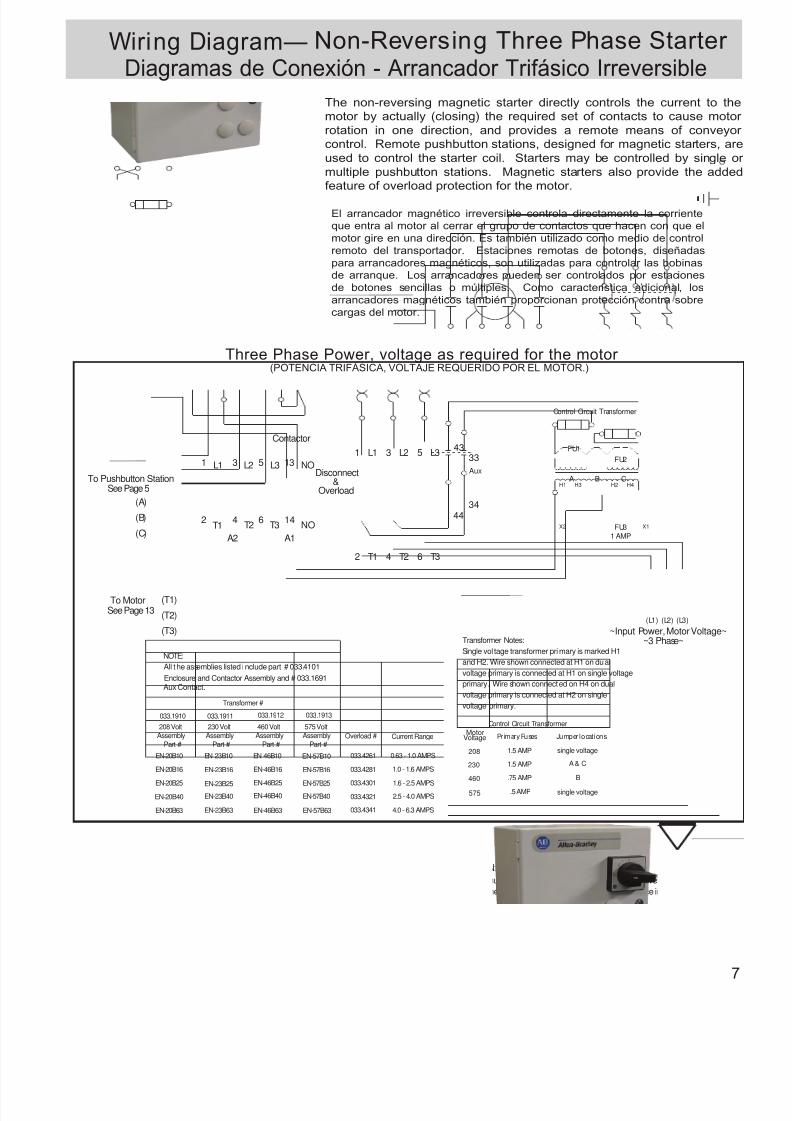
The non-reversing magnetic starter directly controls the current to the
motor by actually (closing) the required set of contacts to cause motor
rotation in one direction, and provides a remote means of conveyor
control. Remote pushbutton stations, designed for magnetic starters, are
used to control the starter coil. Starters may be controlled by single or
multiple pushbutton stations. Magnetic starters also provide the added
feature of overload protection for the motor.
3 5 13
1464
1
2T2 T3T1 NO
L1 L2 L3 NO
A2 A1
(B)
(C)
(A)
To Pushbutton Station
(T1)
(T2)
(T3)
To Motor
L1 3 L2 5 L31
2 T1 4 T2 6 T3
ATTENTION:
Line input must be installed on the bottom side of the overload!
X1X2
H4H2H3H1
FU1
FU2
FU3
A CB
1 AMP
44
43
34
33
~Input Power, Motor Voltage~~3 Phase~
(L1) (L2) (L3)
Contactor
Disconnect&
Overload
Aux
Control Circuit Transformer
6.3 - 10 AMPS
4.0 - 6.3 AMPS
2.5 - 4.0 AMPS1.6 - 2.5 AMPS
1.0 - 1.6 AMPS
0.63 - 1.0 AMPS
033.4361
033.4341
033.4321033.4301
033.4281
033.4261
EN-57B40EN-57B25
EN-57B16
EN-57B10
EN-46B40EN-46B25
EN-46B16EN-23B16
EN-23B25EN-23B40
EN-23B63
EN-23C10
EN-23B10 EN-46B10
EN-46B63
EN-46C10
EN-57B63
EN-57C10EN-20C10
EN-20B40
EN-20B63
EN-20B25
EN-20B16
EN-20B10
Current RangeOverload #
033.1910 033.1911 033.1912 033.1913
Transformer #
208 Volt
Assembly
Part #
230 Volt
Assembly
Part #
460 Volt
Assembly
Part #
575 Volt
Assembly
Part #Primary Fuses Jumper locations
Control Circuit Transformer
208
230
460
575
1.5 AMP
1.5 AMP
.75 AMP
.5 AMP single voltage
single voltage
A & C
B
MotorVoltage
Transformer Notes:
Single vol tage transformer primary is marked H1
and H2. Wire shown connected at H1 on dual
voltage primary is connected at H1 on single voltage
primary. Wire shown connected on H4 on dual
voltage primary is connected at H2 on single
voltage primary.
NOTE:
All the assemblies listed i nclude part # 033.4101
Enclosure and Contactor Assembly and # 033.1691Aux Contact.
See Page 5
See Page 13
and disconnect to meet requirements for UL Compliance in this starter.
Three Phase Power, voltage as required for the motor
7
Wiring Diagram— Non-Reversing Three Phase Starter
(POTENCIA TRIFÁSICA, VOLTAJE REQUERIDO POR EL MOTOR.)
Diagramas de Conexión - Arrancador Trifásico Irreversible
El arrancador magnético irreversible controla directamente la corriente
que entra al motor al cerrar el grupo de contactos que hacen con que el
motor gire en una dirección. Es también utilizado como medio de control
remoto del transportador. Estaciones remotas de botones, diseñadas
para arrancadores magnéticos, son utilizadas para controlar las bobinas
de arranque. Los arrancadores pueden ser controlados por estaciones
de botones sencillas o múltiples. Como característica adicional, los
arrancadores magnéticos también proporcionan protección contra sobre
cargas del motor.
8/13/2019 Im Electricalwiring 021209
http://slidepdf.com/reader/full/im-electricalwiring-021209 8/16
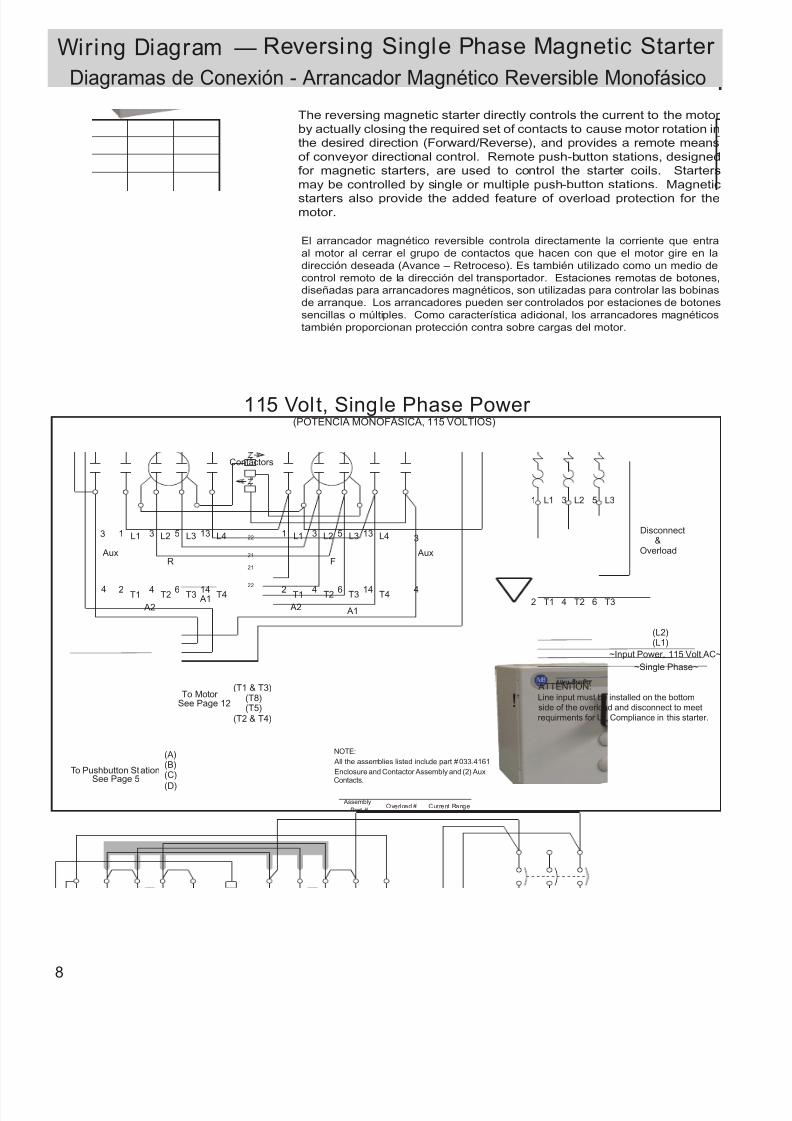
The reversing magnetic starter directly controls the current to the motor
by actually closing the required set of contacts to cause motor rotation in
the desired direction (Forward/Reverse), and provides a remote means
of conveyor directional control. Remote push-button stations, designed
for magnetic starters, are used to control the starter coils. Starters
may be controlled by single or multiple push-button stations. Magnetic
starters also provide the added feature of overload protection for themotor.
L1 3 L2 5 L31
2 T1 4 T2 6 T3
3 5 13
1464
1
2 T2 T3T1 T4
L1 L2 L3 L4
A2 A2
L4L3L2L1
T4T1 T3T22
1
4 6 14
1353
FR
A1
A1
22
21
21
22
Contactors
To Pushbutton Station
(D)
(C)(B)(A)
(T1 & T3)
(T2 & T4)
(T8)(T5)
To Motor
3
44
3
ER-1SC10
ER-1SC20
ER-1SC16
033.4401
033.4381
033.4361
16 - 20 AMPS
10 - 16 AMPS
6.3 - 10 AMPS
Overload # Current Range Assembly
Part #
NOTE:
All the assemblies listed include part # 033.4161
Enclosure and Contactor Assembly and (2) AuxContacts.
Aux Aux
!requirments for UL Compliance in this starter.
side of the overload and disconnect to meet
Line input must be installed on the bottom
ATTENTION:
~Input Power, 115 Volt AC~
~Single Phase~
(L1)(L2)
Disconnect&
Overload
See Page 5
See Page 12
115 Volt, Single Phase Power
8
Wiring Diagram — Reversing Single Phase Magnetic Starter
El arrancador magnético reversible controla directamente la corriente que entra
al motor al cerrar el grupo de contactos que hacen con que el motor gire en la
dirección deseada (Avance – Retroceso). Es también utilizado como un medio de
control remoto de la dirección del transportador. Estaciones remotas de botones,
diseñadas para arrancadores magnéticos, son utilizadas para controlar las bobinas
de arranque. Los arrancadores pueden ser controlados por estaciones de botones
sencillas o múltiples. Como característica adicional, los arrancadores magnéticos
también proporcionan protección contra sobre cargas del motor.
(POTENCIA MONOFÁSICA, 115 VOLTIOS)
Diagramas de Conexión - Arrancador Magnético Reversible Monofásico
8/13/2019 Im Electricalwiring 021209
http://slidepdf.com/reader/full/im-electricalwiring-021209 9/16
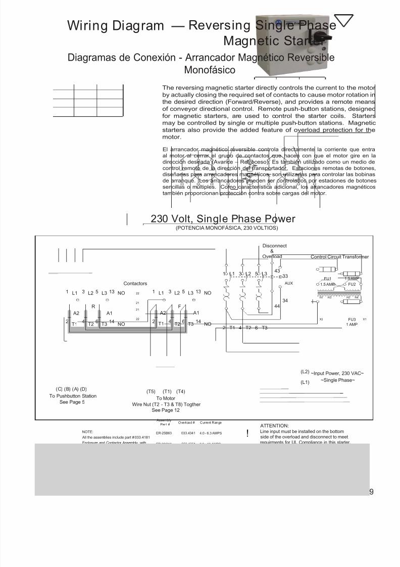
230 Volt, Single Phase Power
The reversing magnetic starter directly controls the current to the motor
by actually closing the required set of contacts to cause motor rotation in
the desired direction (Forward/Reverse), and provides a remote means
of conveyor directional control. Remote push-button stations, designed
for magnetic starters, are used to control the starter coils. Starters
may be controlled by single or multiple push-button stations. Magnetic
starters also provide the added feature of overload protection for the
motor.
3 5 13
1464
1
2T2 T3 NO
L1 L2 L3 NONOL3L2L1
NOT1 T3T22
1
4 6 14
1353
FR
6.3 - 10 AMPSER-2SC10 033.4361
10 - 16 AMPS033.4381ER-2SC16
ER-2SB63 033.4341 4.0 - 6.3 AMPS
Contactors
(C) (B) (A) (D)
To Pushbutton Station
part # 033.1911 Control Circuit Transformer
NOTE:
All the assemblies include part # 033.4181
Enclosure and Contactor Assembly, with
22
21
21
22
Overload # Current Range Assembly
Par t #
!requirments for UL Compliance in this starter.
side of the overload and disconnect to meetLine input must be installed on the bottom
ATTENTION:
X1X2
H4H2H3H1
FU1
FU2
FU3
1.5 AMP
1.5 AMP
1 AMP
L1 3 L2 5 L31
2 T1 4 T2 6 T3
33
34
43
44
(L2)
(L1)
~Input Power, 230 VAC~
~Single Phase~
Disconnect&
Overload Control Circuit Transformer
AUX
and # 033.1691 Aux Contact.
A2 A1
T1
(T1) (T4)(T5)
To Motor
A2 A1
Wire Nut (T2 - T3 & T8) Togther See Page 5
See Page 12
9
Wiring Diagram — Reversing Single Phase
Magnetic Starter
El arrancador magnético reversible controla directamente la corriente que entra
al motor al cerrar el grupo de contactos que hacen con que el motor gire en la
dirección deseada (Avance – Retroceso). Es también utilizado como un medio de
control remoto de la dirección del transportador. Estaciones remotas de botones,
diseñadas para arrancadores magnéticos, son utilizadas para controlar las bobinas
de arranque. Los arrancadores pueden ser controlados por estaciones de botones
sencillas o múltiples. Como característica adicional, los arrancadores magnéticos
también proporcionan protección contra sobre cargas del motor.
(POTENCIA MONOFÁSICA, 230 VOLTIOS)
Diagramas de Conexión - Arrancador Magnético ReversibleMonofásico
8/13/2019 Im Electricalwiring 021209
http://slidepdf.com/reader/full/im-electricalwiring-021209 10/16
3 5 13
1464
1
2T2 T3T1 NO
L1 L2 L3 NO
A2 A1
To Pushbutton Station
(B)
(C)
(A)
(T1)
To Motor
Contactor
L1 3 L2 5 L31
2 T1 4 T2 6 T3
Disconnect&
Overload
~Input Power, 115 Volt AC~
~Single Phase~
(T2)
6.3 - 10 AMPS
10 - 16 AMPS
16 - 20 AMPS
033.4361
033.4381
033.4401
EN-1SC16
EN-1SC20
EN-1SC10
ATTENTION:Line input must be installed on the bottom
side of the overload and disconnect to meet
requirments for UL Compliance in this starter.
!
Enclosure and Contactor Assembly.
All the assemblies listed include part # 033.4121NOTE:
Assembly
Part #Overload # Current Range
(L2)(L1)
See Page 5
See Page 12
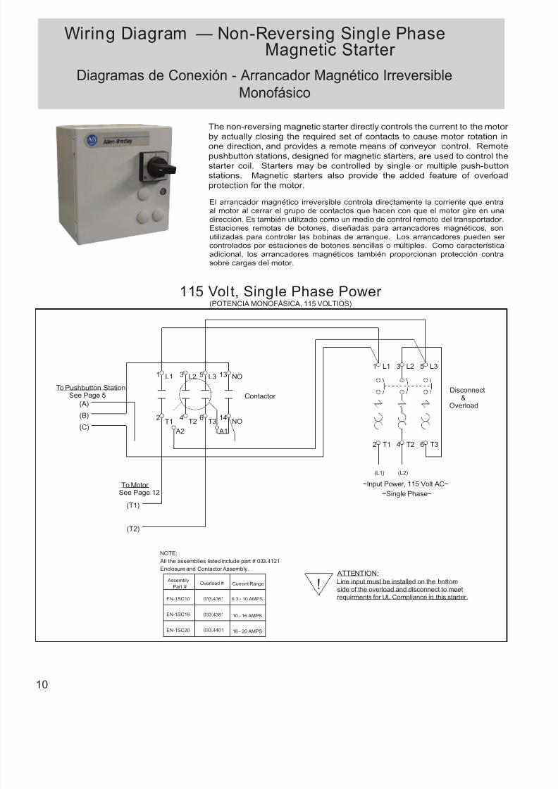
The non-reversing magnetic starter directly controls the current to the motor
by actually closing the required set of contacts to cause motor rotation inone direction, and provides a remote means of conveyor control. Remote
pushbutton stations, designed for magnetic starters, are used to control the
starter coil. Starters may be controlled by single or multiple push-button
stations. Magnetic starters also provide the added feature of overload
protection for the motor.
115 Volt, Single Phase Power
10
Wiring Diagram — Non-Reversing Single PhaseMagnetic Starter
El arrancador magnético irreversible controla directamente la corriente que entra
al motor al cerrar el grupo de contactos que hacen con que el motor gire en una
dirección. Es también utilizado como un medio de control remoto del transportador.
Estaciones remotas de botones, diseñadas para arrancadores magnéticos, son
utilizadas para controlar las bobinas de arranque. Los arrancadores pueden ser
controlados por estaciones de botones sencillas o múltiples. Como característica
adicional, los arrancadores magnéticos también proporcionan protección contra
sobre cargas del motor.
(POTENCIA MONOFÁSICA, 115 VOLTIOS)
Diagramas de Conexión - Arrancador Magnético IrreversibleMonofásico
8/13/2019 Im Electricalwiring 021209
http://slidepdf.com/reader/full/im-electricalwiring-021209 11/16
3 5 13
1464
1
2T2 T3T1 NO
L1 L2 L3 NO
A2 A1
To Pushbutton Station
(B)
(C)
(A)
(T1)
To Motor
(T2)
4.0 - 6.3 AMPS033.4341EN-2SB63
EN-2SC16 033.4381 10 - 16 AMPS
033.4361EN-2SC10 6.3 - 10 AMPS
Overload # Current Range Assembly
Part #
Contactor
L1 3 L2 5 L31
2 T1 4 T2 6 T3
44
43
34
33
1 AMP
FU3
FU2
FU1
H1 H3 H2 H4
X2 X1
1.5 AMP
1.5 AMP
(L1)
~Input Power, 230 Volt AC~
~Single Phase~
ATTENTION:Line input must be installed on the bottom
side of the overload and disconnect to meet
requirments for UL Compliance in this starter.
!
Control CircuitTransformer
AUX
Enclosure and Contactor Assembly, with
All the assemblies listed include part # 033.4121
NOTE:
part # 033.1911 Control Circuit Transformer
and Aux Contact # 033.1691
Disconnect&
Overload
(L2)
See Page 5
See Page 12
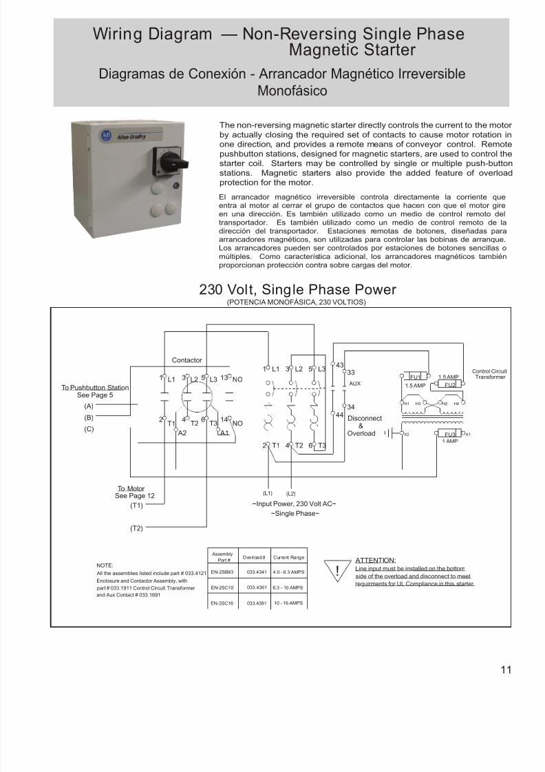
The non-reversing magnetic starter directly controls the current to the motor
by actually closing the required set of contacts to cause motor rotation inone direction, and provides a remote means of conveyor control. Remote
pushbutton stations, designed for magnetic starters, are used to control the
starter coil. Starters may be controlled by single or multiple push-button
stations. Magnetic starters also provide the added feature of overload
protection for the motor.
230 Volt, Single Phase Power
11
Wiring Diagram — Non-Reversing Single PhaseMagnetic Starter
El arrancador magnético irreversible controla directamente la corriente que
entra al motor al cerrar el grupo de contactos que hacen con que el motor gire
en una dirección. Es también utilizado como un medio de control remoto del
transportador. Es también utilizado como un medio de control remoto de la
dirección del transportador. Estaciones remotas de botones, diseñadas para
arrancadores magnéticos, son utilizadas para controlar las bobinas de arranque.
Los arrancadores pueden ser controlados por estaciones de botones sencillas o
múltiples. Como característica adicional, los arrancadores magnéticos también
proporcionan protección contra sobre cargas del motor.
(POTENCIA MONOFÁSICA, 230 VOLTIOS)
Diagramas de Conexión - Arrancador Magnético IrreversibleMonofásico
8/13/2019 Im Electricalwiring 021209
http://slidepdf.com/reader/full/im-electricalwiring-021209 12/16
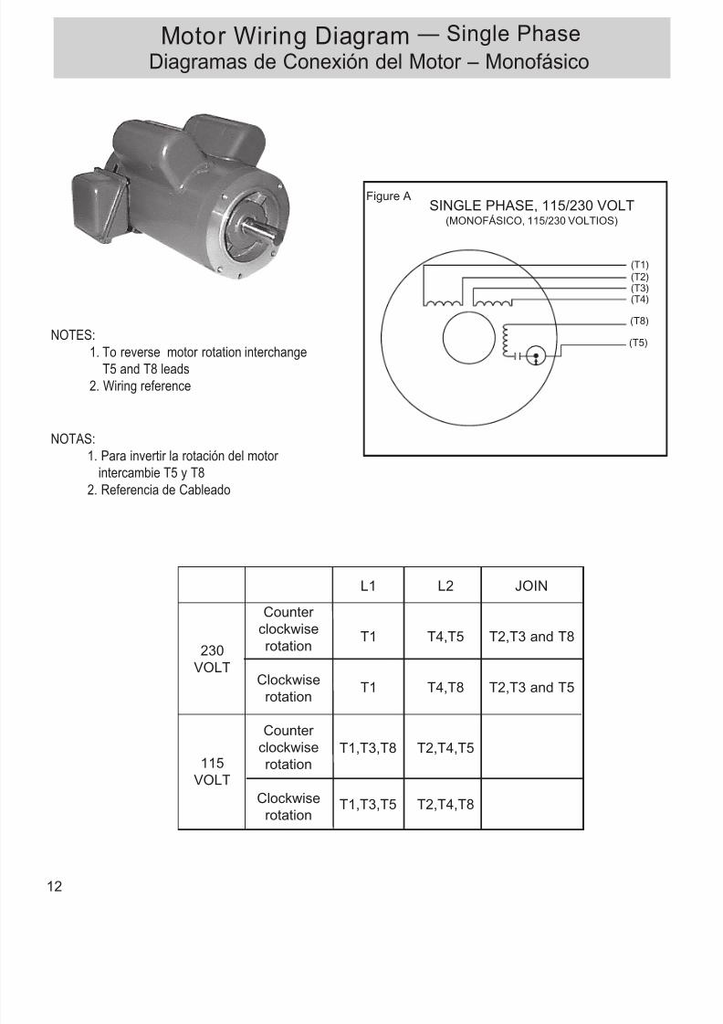
Counter
clockwise
rotation
Clockwise
rotation
Counter
clockwise
rotation
Clockwise
rotation
L1 L2 JOIN
T1 T4,T5 T2,T3 and T8
T1 T4,T8 T2,T3 and T5
T1,T3,T8 T2,T4,T5
T1,T3,T5 T2,T4,T8
230
VOLT
115
VOLT
NOTES:
1. To reverse motor rotation interchangeT5 and T8 leads
2. Wiring reference
SINGLE PHASE, 115/230 VOLTFigure A
(T1)
(T2)(T3)(T4)
(T8)
(T5)
12
Motor Wiring Diagram — Single Phase
NOTAS: 1. Para invertir la rotación del motor intercambie T5 y T8 2. Referencia de Cableado
(MONOFÁSICO, 115/230 VOLTIOS)
Diagramas de Conexión del Motor – Monofásico
8/13/2019 Im Electricalwiring 021209
http://slidepdf.com/reader/full/im-electricalwiring-021209 13/16
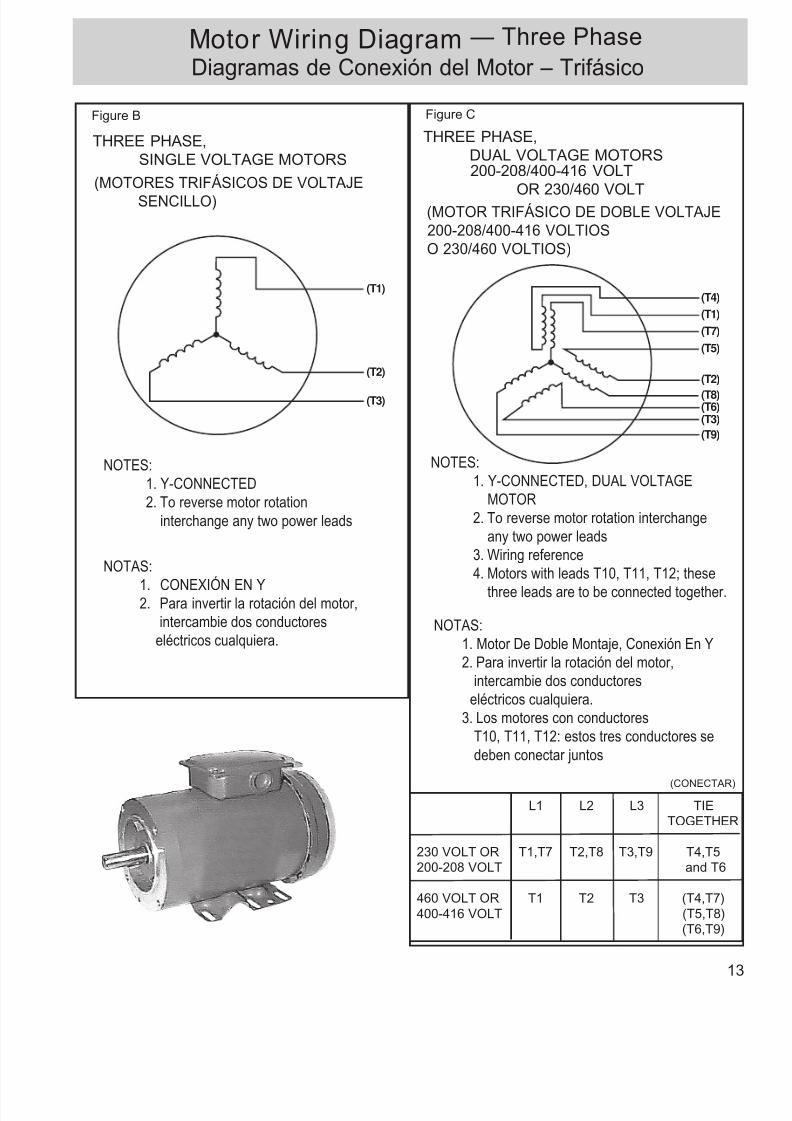
(T3)
(T2)
(T1)
THREE PHASE,
SINGLE VOLTAGE MOTORS
Figure B
NOTES:
1. Y-CONNECTED
2. To reverse motor rotation
interchange any two power leads
NOTES:
1. Y-CONNECTED, DUAL VOLTAGE
MOTOR
2. To reverse motor rotation interchange
any two power leads
3. Wiring reference
4. Motors with leads T10, T11, T12; these
three leads are to be connected together.
L1 L2 L3 TIE
TOGETHER
230 VOLT OR T1,T7 T2,T8 T3,T9 T4,T5
200-208 VOLT and T6
460 VOLT OR T1 T2 T3 (T4,T7)
400-416 VOLT (T5,T8)
(T6,T9)
THREE PHASE,
DUAL VOLTAGE MOTORS
Figure C
(T9)
(T3)(T6)(T8)
(T2)
(T5)
(T7)
(T1)
(T4)
13
Motor Wiring Diagram — Three Phase
200-208/400-416 VOLT
OR 230/460 VOLT
NOTAS:
1. CONEXIÓN EN Y 2. Para invertir la rotación del motor,intercambie dos conductores
eléctricos cualquiera.NOTAS:
1. Motor De Doble Montaje, Conexión En Y 2. Para invertir la rotación del motor, intercambie dos conductores eléctricos cualquiera. 3. Los motores con conductores T10, T11, T12: estos tres conductores se deben conectar juntos
(CONECTAR)
Diagramas de Conexión del Motor – Trifásico
(MOTORES TRIFÁSICOS DE VOLTAJE
SENCILLO) (MOTOR TRIFÁSICO DE DOBLE VOLTAJE 200-208/400-416 VOLTIOS O 230/460 VOLTIOS)
8/13/2019 Im Electricalwiring 021209
http://slidepdf.com/reader/full/im-electricalwiring-021209 14/16
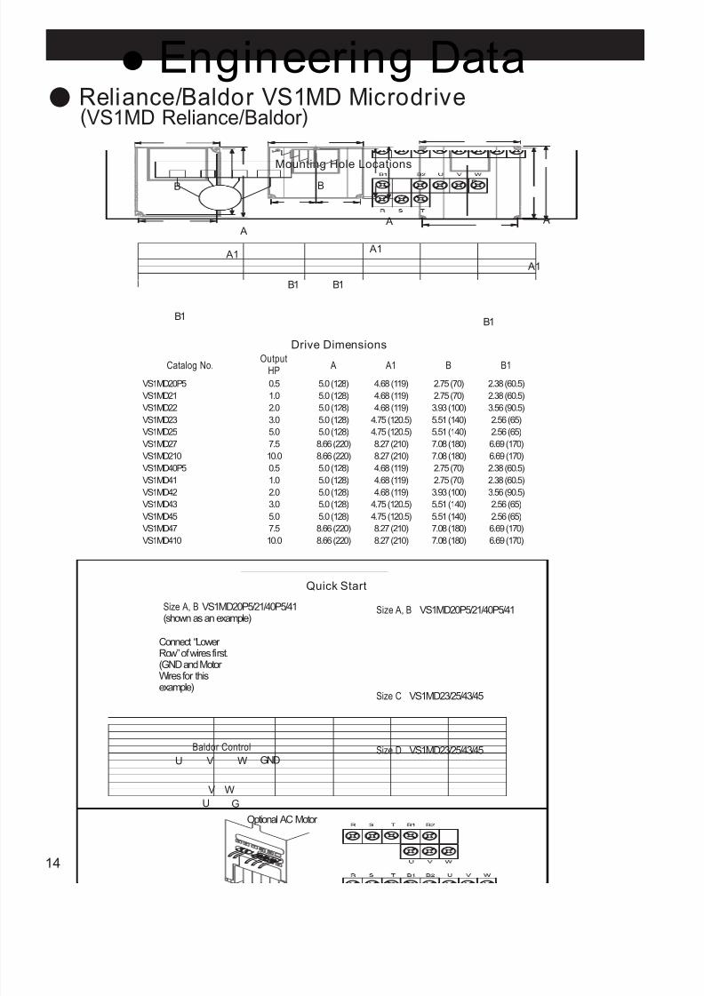
l Engineering Data
Mounting Hole Locations
B1
A1
A
B
B1
A1
A
B
B1
A1
A
B
B1
Catalog No.Output
HP A A1 B B1
VS1MD20P5 0.5 5.0 (128) 4.68 (119) 2.75 (70) 2.38 (60.5)
VS1MD21 1.0 5.0 (128) 4.68 (119) 2.75 (70) 2.38 (60.5)
VS1MD22 2.0 5.0 (128) 4.68 (119) 3.93 (100) 3.56 (90.5)
VS1MD23 3.0 5.0 (128) 4.75 (120.5) 5.51 (140) 2.56 (65)
VS1MD25 5.0 5.0 (128) 4.75 (120.5) 5.51 (140) 2.56 (65)
VS1MD27 7.5 8.66 (220) 8.27 (210) 7.08 (180) 6.69 (170)
VS1MD210 10.0 8.66 (220) 8.27 (210) 7.08 (180) 6.69 (170)
VS1MD40P5 0.5 5.0 (128) 4.68 (119) 2.75 (70) 2.38 (60.5)
VS1MD41 1.0 5.0 (128) 4.68 (119) 2.75 (70) 2.38 (60.5)
VS1MD42 2.0 5.0 (128) 4.68 (119) 3.93 (100) 3.56 (90.5)
VS1MD43 3.0 5.0 (128) 4.75 (120.5) 5.51 (140) 2.56 (65)
VS1MD45 5.0 5.0 (128) 4.75 (120.5) 5.51 (140) 2.56 (65)
VS1MD47 7.5 8.66 (220) 8.27 (210) 7.08 (180) 6.69 (170)
VS1MD410 10.0 8.66 (220) 8.27 (210) 7.08 (180) 6.69 (170)
Size A, B VS1MD20P5/21/40P5/41
Size C VS1MD23/25/43/45
Size D VS1MD23/25/43/45
Size A, B VS1MD20P5/21/40P5/41(shown as an example)
Connect “Lower Row” of wires first.(GND and Motor Wires for thisexample)
Baldor Control
Optional AC Motor
U V W
U
V W
G
GND
Drive Dimensions
Quick Start
l Reliance/Baldor VS1MD Microdrive
14
(VS1MD Reliance/Baldor )
8/13/2019 Im Electricalwiring 021209
http://slidepdf.com/reader/full/im-electricalwiring-021209 15/16
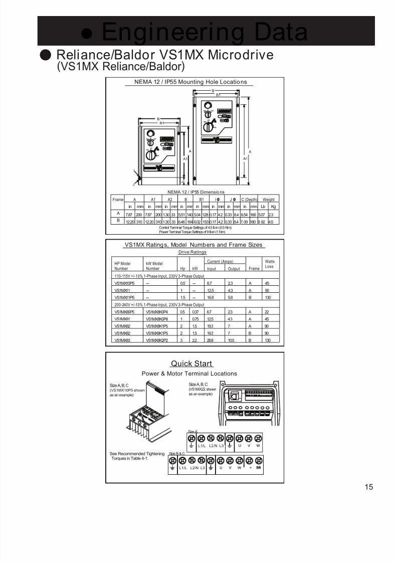
l Engineering Data
NEMA 12 / IP55 Mounting Hole Locations
B1
A1
A
B
A1
A
B1B
I
J A2
STOP
RESET
START PROG
ENT
STOP
RESET
START PROG
ENT
NEMA 12 / IP55 Dimensio ns
A A1 A2 B B1 I Φ J Φ C (Depth) WeightFrame
in mm in mm in mm in mm in mm in mm in mm in mm Lb Kg
A 7.87 200 7.87 200 1.30 33 5.51 140 5.04 128 0.17 4.2 0.33 8.4 6.54 166 5.07 2.3
B 12.20 310 12.20 310 1.30 33 6.46 164 6.02 153 0.17 4.2 0.33 8.4 7.09 180 9.92 4.5
Control Terminal Torque Settings of 4.5 lb-in (0.5 Nm)Power Terminal Torque Settings of 9 lb-in (1 Nm)
VS1MX Ratings, Model Numbers and Frame SizesDrive Ratings
Current (Amps)HP ModelNumber
kW ModelNumber Hp kW Input Output Frame
WattsLoss
110-115V +/-10% 1-Phase Input, 230V 3-Phase Output
VS1MX10P5 --- 0.5 --- 6.7 2.3 A 45
VS1MX11 --- 1 --- 12.5 4.3 A 90
VS1MX11P5 --- 1.5 --- 16.8 5.8 B 130
200-240V +/-10% 1-Phase Input, 230V 3-Phase Output
VS1MX80P5 VS1MX8K0P4 0.5 0.37 6.7 2.3 A 22
VS1MX81 VS1MX8K0P8 1 0.75 12.5 4.3 A 45
VS1MX82 VS1MX8K1P5 2 1.5 19.3 7 A 90
VS1MX82 VS1MX8K1P5 2 1.5 19.3 7 B 90
VS1MX83 VS1MX8K2P2 3 2.2 28.8 10.5 B 130
Quick Start
Power & Motor Terminal Locations
Size A, B, C(VS1MX10P5 shown
as an example)
See Recommended TighteningTorques in Table 4-1.
L1/L L2/N L3
L1/L L2/N L3
Size A
Size B & C
+
Size A, B, C(VS1MX22 shown
as an example)
l Reliance/Baldor VS1MX Microdrive
15
(VS1MX Reliance/Baldor )

8/13/2019 Im Electricalwiring 021209
http://slidepdf.com/reader/full/im-electricalwiring-021209 16/16
HYTROL CONVEYOR COMPANY, INC.2020 Hytrol Street
Jonesboro, Arkansas 72401
Phone: (870) 935-3700
EFFECTIVE February 2009
Printed in the USA by Toof Printing


![Dissertacao de Maria de Lourdes de Queiroz a Hanseniase No Estado de Mato Grosso [97 021209 SES MT]](https://static.fdocument.pub/doc/165x107/55cf98f5550346d0339ab2bf/dissertacao-de-maria-de-lourdes-de-queiroz-a-hanseniase-no-estado-de-mato-grosso.jpg)