II FS Instalacion Dampers
7
Member of AMCA Division of Mestek April 2007 AIR B AL ANCE INSTALL ATION INSTRU CTION Standard Installation Combination Fire/Smoke Damper Models: FS1, FS2, FT1, FT2, FA1, FA2, TA1, TA2 Fire Damper Model s: MD19, MD39, MA19, MA39 ___ __ __ ____ __ __ ____ __ __ ____ __ __ __ ____ __ __ __ __ __ ___ APPLICATI ON These dynamically rated fire/smoke and fire dampers are intended to restrict the passage of flame. The dynamically rated fire/smoke dampers are also intended to restrict the passage of smoke. When the damper is intended to be used as a fire rated damper, the standard ins tallation requires that the damper is positioned so that the closed plane of the blades is within the fire rated masonry/concrete or metal or wood framed gypsum wallboard barrier. When the damper is to be used as a leakage rated damper only, the damper is to be installed within 24" of the smoke barrier and upstream of any duct outlets. This damper may be mounted in the vertical or horizontal position with the damper blades running horizontally. Airflow can be from either direction. When mounted in the vertical position, the damper may be mounted right side up or upside down and can be mounted in a fire barrier constructed of masonry/concrete or metal or wood framed gyps um wallboard materials. When mounted in the horizontal position, the damper must be mounted with the actuator on the top side of the floor and can only be mounted in a fire barrier constructed of masonry/concrete materials. __ __ __ __ __ __ __ __ __ __ __ __ __ __ _____ ____ __ __ __ __ __ __ __ __ ___ MULTIPLE PANEL SIZE LIMITATIONS _____________ _______________ SUPPLEMENTAL INSTALL ATION INSTR UCTIONS / SUBMITTAL DA TA One-Side Retaining Angles (II-FSOS) Out-of-Wall/Floor Sleeve Extension Integral Duct Access Door Electric or Pneumatic Heat Response Device (SD-EHRD or SD-PHRD) Integral Dual Position Indication (SD-IDPI) Electric or Pneumatic Sensotherm (SD-ESOT or SD-PSOT) Flow-Rated Smoke Detector (SM-501) No-Flow Smoke Detector (2151) Transitions (SD-TRFS) Sleeves (SD-SLVFS) II-FS-07.04 Page 1 of 6 Actuation Orientation Assembly Max Panel Max Assy 250° Max Assy 350° Max Panel Max Assy 250° Max Assy 350° FS1, FS2 36"Wx48"H 72"Wx48"H 72"Wx48"H 36"Wx48"H 48"Wx36"H 144 "Wx70"H 128"Wx62" H FT1, FT2 30"Wx48"H 36"Wx30"H 60"Wx48"H 60"Wx48"H 36"Wx48"H 42"Wx36"H 126 " Wx48"H 126" Wx48 "H FA1, FA2 32"Wx48"H 96"Wx96"H 96"Wx96"H 32"Wx48"H 128"Wx96"H 128"Wx96"H TA1, TA2 30"Wx48"H 60"Wx48"H 60"Wx48"H 30"Wx48"H 60"Wx48"H 60"Wx48"H Actuation Orientation Assembly Max Panel Max Assy 250° Max Assy 350° Max Panel Max Assy 250° Max Assy 350° FS1, FS2 36"Wx48"H 72"Wx48"H 72"Wx48"H 36"Wx48"H 108"Wx48"H 108"Wx48"H FT1, FT2 30"Wx48"H 36"Wx30"H 60"Wx48"H 60"Wx48"H 36"Wx48"H 42"Wx36"H 126 "Wx48"H 126"Wx48" H FA1, FA2 32"Wx48"H 96"Wx96"H 96"Wx96"H 32"Wx48"H 128"Wx96"H 128"Wx96"H TA1, TA2 30"Wx48"H 60"Wx48"H 60"Wx48"H 30"Wx48"H 60"Wx48"H 60"Wx48"H Actuation Orientation Assembly Max Panel Max Assy 165° Max Assy 212° Max Panel Max Assy 165° Max Assy 212° MD19 36"Wx48"H 72"Wx48"H 72"Wx48"H 36"Wx48"H 72"Wx60"H 126"Wx48"H 72"Wx60"H 126"Wx48"H MD39 30"Wx48"H 36"Wx30"H 60"Wx48"H 60"Wx48"H 36"Wx48"H 126"Wx48"H 126"Wx48"H MA19 32"Wx48"H 64"Wx36"H 32"Wx72"H 64"Wx36"H 32"Wx72"H 32"Wx48"H 64"Wx36"H 32"Wx72"H 64"Wx36"H 32"Wx72"H MA39 30"Wx48"H 60"Wx36"H 60"Wx36"H 30"Wx48"H 60"Wx36"H 60"Wx36"H M o d e l M o d e l M o d e l Non-Motorized Horizontal Vertical Horizontal Vertical Electric Pneumatic Horizontal Vertical
Transcript of II FS Instalacion Dampers

7/27/2019 II FS Instalacion Dampers
http://slidepdf.com/reader/full/ii-fs-instalacion-dampers 1/6
Member of AMCA
Division of Mestek
April 2007 AIR BALANCE INSTALLATION INSTRUCTION
Standard InstallationCombination Fire/Smoke Damper Models: FS1, FS2, FT1, FT2, FA1, FA2, TA1, TA2
Fire Damper Models: MD19, MD39, MA19, MA39
_____________________________________________________________________________________________________________________________________________________________________________
APPLICATION
These dynamically rated fire/smoke and fire dampers are intended to restrict the passage of flame. The dynamically rated fire/smoke dampers a
also intended to restrict the passage of smoke. When the damper is intended to be used as a fire rated damper, the standard installation require
that the damper is positioned so that the closed plane of the blades is within the fire rated masonry/concrete or metal or wood framed gypsum
wallboard barrier. When the damper is to be used as a leakage rated damper only, the damper is to be installed within 24" of the smoke barrier
and upstream of any duct outlets.
This damper may be mounted in the vertical or horizontal position with the damper blades running horizontally. Airflow can be from either directio
When mounted in the vertical position, the damper may be mounted right side up or upside down and can be mounted in a fire barrier constructe
of masonry/concrete or metal or wood framed gypsum wallboard materials. When mounted in the horizontal position, the damper must be moun
with the actuator on the top side of the floor and can only be mounted in a fire barrier constructed of masonry/concrete materials. _____________________________________________________________________________________________________________________________________________________________________________
MULTIPLE PANEL SIZE LIMITATIONS
______________________________________________________________________________
SUPPLEMENTAL INSTALLATION INSTRUCTIONS / SUBMITTAL DATA
One-Side Retaining Angles (II-FSOS)
Out-of-Wall/Floor
Sleeve Extension
Integral Duct Access Door
Electric or Pneumatic Heat Response Device (SD-EHRD or SD-PHRD)
Integral Dual Position Indication (SD-IDPI)
Electric or Pneumatic Sensotherm (SD-ESOT or SD-PSOT)
Flow-Rated Smoke Detector (SM-501)
No-Flow Smoke Detector (2151)
Transitions (SD-TRFS)
Sleeves (SD-SLVFS)
II-FS-07Page 1
Actuation
Orientation Assembly Max Panel Max Assy 250° Max Assy 350° Max Panel Max Assy 250° Max Assy 350°
FS1, FS2 36"Wx48"H 72"Wx48"H 72"Wx48"H36"Wx48"H
48"Wx36"H144"Wx70"H 128"Wx62"H
FT1, FT230"Wx48"H
36"Wx30"H60"Wx48"H 60"Wx48"H
36"Wx48"H
42"Wx36"H126"Wx48"H 126"Wx48"H
FA1, FA2 32"Wx48"H 96"Wx96"H 96"Wx96"H 32"Wx48"H 128"Wx96"H 128"Wx96"H
TA1, TA2 30"Wx48"H 60"Wx48"H 60"Wx48"H 30"Wx48"H 60"Wx48"H 60"Wx48"H
Actuation
Orientation
Assembly Max Panel Max Assy 250° Max Assy 350° Max Panel Max Assy 250° Max Assy 350°
FS1, FS2 36"Wx48"H 72"Wx48"H 72"Wx48"H 36"Wx48"H 108"Wx48"H 108"Wx48"H
FT1, FT230"Wx48"H
36"Wx30"H60"Wx48"H 60"Wx48"H
36"Wx48"H
42"Wx36"H126"Wx48"H 126"Wx48"H
FA1, FA2 32"Wx48"H 96"Wx96"H 96"Wx96"H 32"Wx48"H 128"Wx96"H 128"Wx96"HTA1, TA2 30"Wx48"H 60"Wx48"H 60"Wx48"H 30"Wx48"H 60"Wx48"H 60"Wx48"H
Actuation
Orientation
Assembly Max Panel Max Assy 165° Max Assy 212° Max Panel Max Assy 165° Max Assy 212°
MD19 36"Wx48"H 72"Wx48"H 72"Wx48"H 36"Wx48"H72"Wx60"H
126"Wx48"H
72"Wx60"H
126"Wx48"H
MD3930"Wx48"H
36"Wx30"H60"Wx48"H 60"Wx48"H 36"Wx48"H 126"Wx48"H 126"Wx48"H
MA19 32"Wx48"H64"Wx36"H
32"Wx72"H
64"Wx36"H
32"Wx72"H32"Wx48"H
64"Wx36"H
32"Wx72"H
64"Wx36"H
32"Wx72"H
MA39 30"Wx48"H 60"Wx36"H 60"Wx36"H 30"Wx48"H 60"Wx36"H 60"Wx36"H
M o d e l
M
o d e l
M o d e l
Non-Motorized
Horizontal Vertical
Horizontal Vertical
Electric
Pneumatic
Horizontal Vertical

7/27/2019 II FS Instalacion Dampers
http://slidepdf.com/reader/full/ii-fs-instalacion-dampers 2/6
Member of AMCA
Division of Mestek
April 2007
INSTALLATION
1. General: The installation of the damper and all duct connections to the damper sleeve shall conform to NFPA-90A and the SMACNA Fire, Smoke and Radiation
Damper Installation Guide. All duct connections shall also conform to UL555 when the damper is intended to be used as a fire damper.
2. Actuato rs: Dampers must be supplied with factory mounted actuators (except Model MD19, MD39 and MA19, MA39) and are intended to close automatically when
sensing heat or upon loss of electrical power or release of air pressure. When this damper is used as a leakage rated damper only, it shall be arranged to operate
automatically and is to be controlled by a smoke detector. See additional instructions, which detail damper actuator sequence of operations.
Multiple actuators in a mechanically linked section that are factory wired/plumbed together have only one heat response device and one supply connection point.
The supply connection point must be at the "master" actuator package, which contains the heat response device. The heat response device must be wired/plumbed
between the supply connection point and the master actuator and all slave actuators.
3. Multiple Panel / Multiple Section Assembly: Large damper assembly sizes may require multiple factory assembled modules that ship separately. Refer to page
4 for details.
4. Sleeves: Sleeves are required for the proper installation of fire rated dampers, but need not be factory mounted. Dampers with factory mounted external
actuators can be supplied without sleeves, but require sideplates. Dampers with factory mounted internal actuators can be supplied without sleeves or sideplates.
Sleeves shall be the same gauge or heavier as the duct to which it is attached. Gauges shall conform to SMACNA or ASHRAE duct standards. A field suppliedsleeve is attached to the damper frame with 3/16" diameter steel rivets, 1/4" diameter steel bolts, #10 steel sheet metal screws, or ½" long welds. Fasteners shall
be staggered on each side of the damper frame on 6" maximum centers and 3-½" maximum from each corner. For Class I Fire/Smoke dampers, approved
caulking (reference note 7) shall be applied along the perimeter between the sleeve and the damper on both sides. For Class II Fire/Smoke dampers, approved
caulking (reference note 7) shall be applied along the perimeter between the sleeve and the damper on only one side.
5. Expansion Clearance: The opening in the wall for the fire rated damper shall be sized to provide expansion clearance between the sleeve and the opening. The
minimum expansion clearance shall be the greater of 1/4" or 1/8" per foot of overall damper/sleeve width and height. The maximum expansion clearance shall not
exceed 1/8" per foot of overall damper/sleeve width and height plus 2".
Example: For a damper with exact outside dimensions of 36"W x 48"H, the gap at the top plus the gap at the bottom must be between 0.50" and 2.5". The gap at
the left side plus the gap at the right side must be between 0.375" and 2.375". The damper can be located anywhere in the opening and need not be centered.
6. Retaining Angle At tachment: Perimeter retaining angles shall increase in size, proportionately, so there will be a minimum of 1" overlap on the wall, including atthe corners. The angles shall be flush against the barrier. The leg attached to the damper can turn away from or into the opening. In metal frame construction,the angles can be mounted under or over the gypsum board. In wood frame construction, the angles must be mounted over the gypsum board. The perimeter
mounting angles shall be fastened on all four sides and on both faces of the damper to the sleeve only, with 3/16" diameter steel or stainless steel nuts and bolts or
by tack welding with beads 1/2" ± 1/4" in length or with #10 steel or stainless steel sheet metal screws or 3/16" steel or stainless steel pop rivets. All connections shall
be spaced on 6" maximum centers and 3" maximum from each corner (a minimum of 2 fasteners are required per side). For perimeter angle mounting on one side
of the fire barrier only, reference Installation Instruction II-FSOS. Perimeter retaining angles shall be a minimum of 1-1/2" x 7/8" x 16-GA steel. Corners of angles
are not welded together for dampers with width or height dimensions exceeding 24". For dampers 24"W x 24"H or smaller, the corners of the perimeter mounting
angles can be welded. Some local codes may not allow welded corners. Attachment of these angles must not restrict operation of the damper. Perimeter
retaining angles and their mounting fasteners are not typically supplied with the damper.
7. Caulking: Caulk shall be one of the following: Dow Corning RTV732, Silco Sil-Bond RTV 4500, General Electric IS808, or Novagard RTV300. Caulking is allowed
between the retaining angles and the damper sleeve, and between the retaining angles and the face of the floor or wall construction. Caulking is not allowed
between the damper sleeve and the wall or floor inside the opening.
Breakaway flange caulking shall be Design Polymeric's DP1010 or Precision's PA2084T
8. Duct Connections: All connecting ducts shall not be continuous, but shall terminate at the fire damper sleeve. Duct connections not listed as breakaways shallbe considered rigid. For rigid type duct connections, the sleeve shall be a minimum of 16-GA on dampers not exceeding 36" wide or 24" high or 24" diameter and
14-GA on larger units. Maximum sleeve thickness shall not exceed 10-GA galvanized steel. Dampers supplied with thinner sleeves require a breakaway
connection. The following breakaway duct-to-sleeve connections may be used: Plain “S” Slip, Double “S” Slip, Inside Slip, Hemmed “S” Slip, Standing “S” Slip,
Standing “S” Sl ip (Bar Reinforced), Standing “S” Sl ip (Angle Reinforced), and Standing “S” Slip (Alternate Bar). Breakaway joints shall have no more than two No.
10 sheet metal screws on each side and on the bottom. The screws shall penetrate both sides of the slip pocket. When a breakaway joint is used along the top
and bottom duct connection, a flat drive slip no longer than 20 inches is permitted on the two sides. The damper is normally supplied with a factory attached
sleeve (see Note 4 when field supplied sleeve). The standard factory supplied sleeve is 20-GA galvanized steel (18-GA on dampers wider or higher than 84") and
assumes that a breakaway type duct connection will be employed.
The factory supplied round/oval transition provides the breakaway connection if the following conditions are satisfied.
1. Round duct diameter is no larger that 36".
2. Oval duct size is no larger than 71"W x 30"H.
3. Duct gauges conform to the SMACNA or ASHRAE standard.4. An oval duct or round duct less than or equal to 24" is attached to the transition collar with #8 sheet metal screws (a minimum of 4 fasteners per connection). A round duct diameter greater than 24" is attached to the transition collar with #10 sheet metal screws (a minimum of 5 fasteners per
connection).
Dampers with round/oval transitions that fall outside of these restrictions must use a 4" wide drawband connection as shown in the SMACNA Fire, Smoke, and
Radiation Damper Installation Guide.
9. Maintenance: Dampers shall be maintained at intervals as stated in NFPA 90A and 92A. Local codes or building conditions may require more frequent
inspections and maintenance. A duct access door is to be located on the jackshaft side of each damper for periodic inspection and maintenance.
AIR BALANCE INSTALLATION INSTRUCTION II-FS-07.04Page 2 of 6
Plain "S" Slip Hemmed "S" SlipDouble "S" Slip
Standing "S" Slip
Inside Slip Joint
Standing "S" Slip
(Bar Reinforced)
Standard "S" Slip
(Angle Reinforced)
Standard "S" Slip
(Alternate Bar)

7/27/2019 II FS Instalacion Dampers
http://slidepdf.com/reader/full/ii-fs-instalacion-dampers 3/6
Member of AMCA
Division of Mestek
April 2007
STANDARD MOUNTING DETAILS
Retaining Angle
Overlap
(See Note 6)
ExpansionClearance
(See Note 5)
Duct Connector
(See Note 8)
Ai rf low
6" Maximum
Non-Actuator Side
16" Maximum
Actuator Side
Perimeter
Retaining Angle
(See Note 6)
Vertical, 2-Side Retaining, Masonry Horizontal, 2-Side Retaining, Masonry
Vert ical , 2-Side Retaining, Metal Stud Ver ti cal, 2-Side Retain ing, Wood Stud
Retaining Angle
Overlap
(See Note 6)
Expansion
Clearance(See Note 5)
Duct Connector
(See Note 8)
Ai rf low
6" Maximum
Non-Actuator Side
16" Maximum
Actuator Side
Perimeter
Retaining Angle
(See Note 6)
Retaining Angle
Overlap
(See Note 6)
Expansion
Clearance(See Note 5)
Duct Connector
(See Note 8)
Ai rf low
6" Maximum
Non-Actuator Side
16" Maximum
Actuator Side
Perimeter
Retaining Angle
(See Note 6)
AIR BALANCE INSTALLATION INSTRUCTION II-FS-07Page 3
6" Maximum
Non-Actuator Side
Retaining Angle Overlap(See Note 6)
Expansion Clearance
(See Note 5)
Duct Connector
(See Note 8)
Ai rf low
16" Maximum
Actuator Side
Perimeter
Retaining Angle
(See Note 6)
7/27/2019 II FS Instalacion Dampers
http://slidepdf.com/reader/full/ii-fs-instalacion-dampers 4/6
Member of AMCA
Division of Mestek
April 2007
MULTIPLE PANEL / MULTIPLE SECTION INSTALLATION DETAILS
Fire/Smoke Dampers (Models FS1, FS2, FT1, FT2, FA1, FA2, TA1, TA2)
1. Damper assemblies ordered without factory mounted sleeves are limited in size, so that the entire assembly ships as a single section.
2. Multiple panel high damper assemblies are electrically/pneumatically, but not mechanically linked between top and bottom panels if assembled
within a common sleeve. Large sizes may require multiple sleeve sections - multiple sleeve sections are not mechanically or electrically/
pneumatically linked.
3. Multiple panel wide damper assemblies are mechanically and electrically/pneumatically linked if assembled within a common sleeve. Large
sizes may require multiple sleeve sections - multiple sleeve sections are not mechancially or electrically/pneumatically linked.
4. Damper assembly sections that are not mechanically or electrically/pneumatically linked each have their own heat response device and their
own supply connection point, such that they operate independently. Multiple actuators within a linked section are factory wired/plumbed
together.
5. Damper assembly sections that are mechanically and electrically/pneumatically linked share a single heat response device and a single supply
connection point. Multiple actuators within a linked section are factory wired/plumbed together.
6. Damper assemblies that ship in multiple sections shall be fastened together using 1/4" diameter steel bolts, lockwashers, and nuts. Fasteners
shall be on 6" maximum centers on both faces of the frame.
Fire Dampers (MD19, MD39, MA19, MA39)
1. Damper assemblies ordered without factory mounted sleeves are limited in size, so that the entire assembly ships as a single section.
2. Multiple panel high damper assemblies are not mechanically linked between top and bottom panels.
3. Multiple panel wide damper assemblies are not mechanically linked between panels.
4. Damper assembly sections that are not mechanically linked each have their own heat response device, such that they operate independently.
5. Damper assemblies that ship in multiple sections shall be fastened together using 1/4" diameter steel bolts, lockwashers, and nuts. Fasteners
shall be on 6" maximum centers on both faces of the frame.
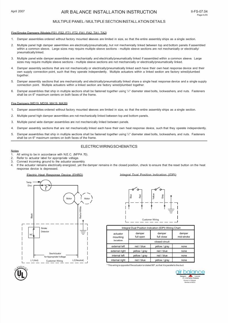
ELECTRIC WIRING SCHEMATICSNotes
1. All wiring to be in accordance with N.E.C. (NFPA 70).
2. Refer to actuator label for appropriate voltage.
3. Connect incoming ground to the actuator assembly.
4. If the actuator remains electrically energized, yet the damper remains in the closed position, check to ensure that the reset button on the heat
response device is depressed.
Temp.
Disc
Smoke
Detector
See Actuator
for Appropriate Voltage
Customer Wiring
NC
Motor Motor
B l a c k
R e d o r W h i t e
B l u e
R e d
Y e l l o w
G r a y
Customer Wiring
Electric Heat Response Device (EHRD) Integral Dual Position Indication (IDPI)
L1 (Hot) L2 (Neutral)
AIR BALANCE INSTALLATION INSTRUCTION II-FS-07.04Page 4 of 6
* This wiring is opposite if the actuator is rotated 90º, so that it is parallel to the duct.
damper
full open
damper
full close
damper
mid-stroke
external left red / blue yellow / gray none
external right yellow / gray red / blue none
internal left yellow / gray red / blue none
internal right red / blue yellow / gray none
Integral Dual Position Indication (IDPI) Wiring Chart
closed circuit
actuator
mounting
location

7/27/2019 II FS Instalacion Dampers
http://slidepdf.com/reader/full/ii-fs-instalacion-dampers 5/6
Member of AMCA
Division of Mestek
April 2007
ESOT/PSOT Wiring, Test, and Operating Instructions
Damper is supplied with one low temperature thermal disc and one high temperature thermal disc. All dampers require a master control switch
(supplied by others) for re-openable operation.
CUSTOMER WIRING
1. Connect input power lead L1 from the normal closed position lead of the (MCS) switch to damper lead L1.
Note: If a smoke detector or other sensing device is to be employed, its NC contact set should be wired in series between the (MCS)
position switch normal wire and lead L1.
2. Connect incoming lead L2 to damper lead L2.
3. Connect the reopen switch lead from (MCS) to orange damper lead.
4. Connect the incoming ground lead to the wiring enclosure.
5. Install IDPI (if used) per the schematic.
6. Replace enclosure cover.
CIRCUIT TEST
1. Place (MCS) switch in damper close position.
2. Apply power.
Result: The closed indicator light (if used) should be on and the damper blades closed.
3. Transfer (MCS) switch to damper re-open position.
Result: The damper blades should open; the closed indicator light (if used) should go off and the open indicator light (if used)
should go on.
4. Transfer (MCS) switch to the normal position.
Result: The damper blades should remain open and the open indicator light (if used) should remain on.
5. Transfer the (MCS) switch to the closed position.
Result: The damper blades should close; the open indicator light (if used) should go off and the closed indicator light (if used)
should go on.
EMERGENCY OPERATION (SMOKE MANAGEMENT)
1. MCS closed position: Damper will close regardless of whether the thermal switch device has activated or not and regardless of the
command from the smoke system.
2. MCS re-open position: If the damper has not been exposed to an elevated temperature higher than its rating, the damper will open. Al
the damper will open regardless of whether the low temperature thermal disc (165ºF or 212ºF) has activated or not and regardless of a
command from additional sensing devices, such as a smoke detector.
NOTE: If the master control switch (MCS) is in the re-open position and the high temperature thermal disc has not been tripped, the damper
will remain open regardless of whether the low temperature thermal disc and/or other sensing devices have tripped or not. If the damper h
been exposed to an elevated temperature higher than its temperature degradation rating, or if the electrical or pneumatic supply has been
disconnected, the damper will close and remain closed regardless of any (MCS) position.
ELECTRIC WIRING SCHEMATICS (CONT.)
Low
Temp.
Disc
Smoke
Detector
See Actuator
for Appropriate Voltage
Customer Wiring
NC
Motor
or E.P.
Valve
Motor
or E.P.
Valve
B l a c k
R e d o r W h i t e
B l u e
R e d
Y e l l o w
G r a y
Customer Wiring
High
Temp.
Disc
Electric/Pneumatic Sensotherm (ESOT/PSOT) with included Integral Dual Position Indication (IDPI)
L1 (Hot) L2 (Neutral)
Damper
Re-openDamper
Close SPDT
Center
AIR BALANCE INSTALLATION INSTRUCTION II-FS-07Page 5
O r a n g e
* This wiring is opposite if the actuator is rotated 90º, so that it is parallel to the duct.
damper
full open
damper
full close
damper
mid-stroke
external left red / blue yellow / gray none
external right yellow / gray red / blue none
internal left yellow / gray red / blue noneinternal right red / blue yellow / gray none
Integral Dual Position Indication (IDPI) Wiring Chart
closed circuit
actuator
mounting
location

7/27/2019 II FS Instalacion Dampers
http://slidepdf.com/reader/full/ii-fs-instalacion-dampers 6/6
Member of AMCA
Division of Mestek
April 2007
NOTES:
1. These illustrated partition designs have
successfully been tested in conjunction
with 1-1/2 hour classified fire dampers,
for additional designs, reference
Underwriters Laboratories, Inc. Fire
Resistance Directory. Specific framing
requirements of openings may vary with
the Local Authority that has jurisdiction.
Specific framing requirements should be
provided in the architectural and
structural drawings.
2. Reference the damper's installation
instructions regarding the approved
method of attaching the damper to the
sleeve, attaching the retaining angles to
the sleeve, required expansion clear-
ances, sleeve gauge, etc. Type of
framing does not affect the stated
required expansion clearance.
3. Gypsum panels surrounding the opening
are to be fastened to all stud and runner
flanges, 12" o.c. maximum.
4. When wooden studs are used, filler
pieces must be installed around the entire
opening. Filler pieces are optional whenmetal studs are used (consult local codes
to determine if filler pieces are required).
Filler pieces are to be double screwed (or
nailed to wooden studs) on 12" max.
centers to the web of runners and studs.
5. Double jamb studding shown and
required when opening width or length
exceeds 36". Single jamb studding
acceptable for openings 36"W x 36"H and
smaller.
Min. 1"
Overlap
Min. 1/2" Thick Filler
Piece (See Note 4)
Fire Damper
Sleeve
(See Note 2)
Retaining Angle (May Be
Reversed Providing Adequate
Clearance is Maintained)
Drywall Screws (Metal Studs)
Dw Screws or Nails (Wood Studs)
Min. 1/2" Thick
Gypsum WallboardMin. 2-1/2" Stud
or Runner
Section B-B
(1 Hour Rated Fire Barrier)
Min. 1"
Overlap
Min. 1/2" Thick Filler
Piece (See Note 4)
Fire Damper
Sleeve
(See Note 2)
Retaining Angle (May Be
Reversed Providing Adequate
Clearance is Maintained)
Drywall Screws (Metal Studs)Dw Screws or Nails (Wood Studs)
Min. 1/2" Thick
Gypsum WallboardMin. 2-1/2" Stud
or Runner
Section B-B
(2 Hour Rated Fire Barrier)
Min. 2-1/2" Runner
Min. 2-1/2" Stud
Panhead Screws (Metal Studs)
Nails (Wooden Studs)
4 Per 90º Bend
Section A-A
Local Codes May
Require Double
Header
Ceiling Runner
B
2"
Floor Runner
12"
24"
O.C.
Max
16"
O.C.
Max
2 Fasteners
Runner 90º
Bend
2 Fasteners
B A A
2"
FRAMING DETALS (METAL OR WOOD 1 HOUR AND 2 HOUR RATED BARRIERS)
AIR BALANCE INSTALLATION INSTRUCTION II-FS-07.04Page 6 of 6
Member of AMCA
Division of Mestek