Hybrid CTDMA
12
568 IEEE JOURNAL ON SELECTED AREAS IN COMMUNICATIONS, VOL. 12, NO. 4, MAY 1994 Performance of a Cellular Hybrid C/TDMA Mobile Radio System Applying Joint Detection and Coherent Receiver Antenna Diversity Josef Blanz, Anja Klein, Student Member, IEEE, Markus NaBhan, and Andreas Steil Absfruct -For future mobile radio systems, an appropriately chosen mu ltiple access technique is a critical issue. Multiple access techniques presently under discussion are code division multiple access (CDMA), time division multiple acces s (TDMA), and hy- brids of both. In thi s paper, a hybrid CR DM A system using joint detection (JD-CD'DMA) with coherent receiver antenna diversity (CRAD) at the base station (BS) receiver is proposed. Some attractive features of the JD-C/TDMA system are the possibility to flexibly offer voice and data services with different bit rates, soft capacity, inherent frequency and interferer diversity, and high system capacit y due to JD. Furthermore, due to JD , a cluster size equal to 1 can be realized without needing soft handover. The single cell E~/No erformance and the interference situation in a cellular environment of the uplink of a JD-CD'DMA mobile radio system with CRAD is investigated in detail. It is shown that the cellular spectrum efficiency is remarkably high, taking values up to 0.2 bit/s/Hz/BS in the uplink, depending on the actual transmission conditions. I. INTRODUCTION OR future mobile radio systems, the selection of appro- F riate multiple access techniques is a criti cal issue having major impact on the system capacity or cellular spectrum efficiency, the radio network planning, the services being supported, and the flexibility with respect to further system evolution [ 11. Multiple access techniques presently under discussion are code division multiple access (CDMA), time division multiple access (TDMA), and hybrids of both [2] -[4 ]. Fast frequency hopping (FFH) seems to be a less attractive candidate, mainly due to the sophisticated code management and synthesizers required [l]. Therefore, FFH will not be discussed in this paper. Each conceivable system will most likely include a frequency division multiple access (FDMA) component since the total available system bandwidth has to be split int o subbands for technological reasons, to set up umbrella cells or to support multioperator networks [ 11 . An advanced TDMA system approach could evolve from the present day sta ndards o f the GSM (Global Sys tem for lular), and the JDC (Japanese Digital Cellular) systems [5]. In a TDMA system, the users transmit in bursts, and the bursts of different users, spread in duration due to multipath reception, are separated by setting time windows at the r e- ceiver. This requires multiple access management entailing overheads for protocolling, channel estimation, guard intervals, and synchronization. On the other hand, a TDMA component makes it easily possible to offer voice and data services with different bit rates. TDMA systems are operated with cluster sizes larger than 1 requiring either frequency p lanning or adaptive channel allocation (ACA) [5]. By ACA, channels are allocated depending on the actual traffic and interference situation leading to higher capacity and more flexibility [5]. The CDMA multiple access technique has been especially promoted by the proposal of a CDMA mobil e radio system by Qualcomm, Inc., claiming a large capacity increa se over TDMA [6]. In a CDMA system, a number of user signals ar- rive at the receiver simultaneously i n the same frequency band, only separable by different user-specific signature sequences. Due to time variance and multipath propagation of the mobil e radio channel, both intersymbol interference (ISI) and multiple access intereference (MAI) occur at the receiver. Interference can be treated in the receiver in different ways. Irrespective of the chosen receiver structure, resulting from the larger user bandwidth of CDMA systems as compared to TDMA systems, CDMA systems provide inherent frequency diversity and, due to the larger number of cochannel interferers, inhe rent interferer diversity [7]. Furthermore, CDMA systems provide soft capacity , which means that the number of t raffic channels availa ble in a cell is not strictl y fixed b y the number of time slots and frequency bands available, but is, up to a certain bound, a flexible parameter determined by the amount of interference and the required service quality [ l] , [6]. However, this feature is not relevant in a fully loaded system [l]. A CDMA system can be designed to handle speech and data services with different bit rates and also variable bit-rate services like variable bit-rate speech and packet data since, on the aver age, a service takes only as much of t he capacity of the system as is actually needed [l], [6], [34]. In general, a cluster size of 1 can be realized, requiring no frequency planning [6]. However, even for a cluster size of 1, p lanning of a system with an d adjacent Or overlapping cells of different sizes is necessary [ 11. Basically, two types of receivers may be distinguished: one treating IS1 and MA1 as noise, and the other exploiting same or all Manuscript received June 28 , 1993; revised Nov. 25, 1993. This work was supported by a research contract granted by Siemens AG, Munich, Germany. This paper was presented in part at the International Zurich Seminar, Zurich, March 8-11, 1994. The authors are with the University of Kaiserlautem, D-67653 Kaiser- lautem. Germanv. IEEE Log Nu he r 9215408. knowledge about IS1 and MAL The first type of receiver can 0733-8716/94$04.00 0 1994 IEEE
Transcript of Hybrid CTDMA
7/27/2019 Hybrid CTDMA
http://slidepdf.com/reader/full/hybrid-ctdma 1/12
568 IEEE JOURNAL ON SELECTED AREAS IN COMMUNICATIONS, VOL. 12, NO. 4, MAY 1994
Performance of a Cellular Hybrid C/TDMA
Mobile Radio System Applying Joint Detection
and Coherent Receiver Antenna Diversity
Josef Blanz, Anja Klein, Student Member, IEEE, Markus NaBhan, and Andreas Steil
Absfruct-For future mobile radio systems, an appropriatelychosen mu ltiple access technique is a critical issue. Multiple accesstechniques presently under discussion are code division multipleaccess (CDMA), time division multiple access (TDMA), and hy-brids of both. In this paper, a hybrid CR DM A system using jointdetection (JD-CD'DMA) with coherent receiver antenna diversity(CRAD) at the base station (BS) receiver is proposed. Someattractive features of the JD-C/TDMA system are the possibilityto flexibly offer voice and data services with different bit rates,soft capacity, inherent frequency and interferer diversity, andhigh system capacity due to JD. Furthermore, due to JD , a clustersize equal to 1 can be realized without needing soft handover. Thesingle cell E ~ / N o erformance and the interference situation in
a cellular environment of the uplink of a JD-CD'DMA mobileradio system with CRAD is investigated in detail. It is shownthat the cellular spectrum efficiency is remarkably high, takingvalues up to 0.2 bit/s/Hz/BS in the uplink, depending on the actualtransmission conditions.
I . INTRODUCTION
OR future mobile radio systems, the selection of appro-F riate multiple access techniques is a critical issue having
major impact on the system capacity or cellular spectrum
efficiency, the radio network planning, the services being
supported, and the flexibility with respect to further system
evolution [11. Multiple access techniques presently under
discussion are code division multiple access (CDMA), time
division multiple access (TDMA), and hybrids of both [2]-[4].Fast frequency hopping (FFH) seems to be a less attractive
candidate, mainly due to the sophisticated code management
and synthesizers required [l]. Therefore, FFH will not be
discussed in this paper. Each conceivable system will most
likely include a frequency division multiple access (FDMA)
component since the total available system bandwidth has to
be split into subbands for technological reasons, to set up
umbrella cells or to support multioperator networks [11.
An advanced TDMA system approach could evolve from
the present day standards of the GSM (Global System for
Mobile Communications), the ADC (American Digital Cel-
lular), and the JDC (Japanese Digital Cellular) systems [5].
In a TDMA system, the users transmit in bursts, and the
bursts of different users, spread in duration due to multipath
reception, are separated by setting time windows at the re-
ceiver. This requires multiple access management entailing
overheads for protocolling, channel estimation, guard intervals,
and synchronization. On the other hand, a TDMA component
makes it easily possible to offer voice and data services with
different bit rates. TDMA systems are operated with cluster
sizes larger than 1 requiring either frequency planning or
adaptive channel allocation (ACA) [ 5 ] . By ACA, channels
are allocated depending on the actual traffic and interference
situation leading to higher capacity and more flexibility [5].
The CDMA multiple access technique has been especially
promoted by the proposal of a CDMA mobile radio system
by Qualcomm, Inc., claiming a large capacity increase over
TDMA [6]. In a CDMA system, a number of user signals ar-
rive at the receiver simultaneously in the same frequency band,
only separable by different user-specific signature sequences.
Due to time variance and multipath propagation of the mobile
radio channel, both intersymbol interference (ISI) and multiple
access intereference (MAI) occur at the receiver. Interference
can be treated in the receiver in different ways. Irrespective
of the chosen receiver structure, resulting from the larger
user bandwidth of CDMA systems as compared to TDMA
systems, CDMA systems provide inherent frequency diversity
and, due to the larger number of cochannel interferers, inherentinterferer diversity [7]. Furthermore, CDMA systems provide
soft capacity, which means that the number of traffic channels
available in a cell is not strictly fixed by the number of time
slots and frequency bands available, but is, up to a certain
bound, a flexible parameter determined by the amount of
interference and the required service quality [ l] , [6]. However,
this feature is not relevant in a fully loaded system [l]. A
CDMA system can be designed to handle speech and data
services with different bit rates and also variable bit-rate
services like variable bit-rate speech and packet data since,
on the average, a service takes only as much of the capacity
of the system as is actually needed [l], [6], [34]. In general,
a cluster size of 1 can be realized, requiring no frequency
planning [6]. However, even for a cluster size of 1, planning of
a system with and adjacentOr
overlapping cells of different sizes is necessary [11. Basically,
two types of receivers may be distinguished: one treating
IS1 and MA1 as noise, and the other exploiting same or all
Manuscript received June 28 , 1993; revised Nov. 25, 1993. This work wassupported by a research contract granted by Siemens AG, Munich, Germany.This paper was presented in part at the International Zurich Seminar, Zurich,
March 8-11, 1994.The authors are with the University of Kaiserlautem, D-67653 Kaiser-
lautem. Germanv.IEEE Log Nu h e r 9215408. knowledge about IS1 and MAL The first type of receiver can
0733-8716/94$04.00 0 1994 IEEE

7/27/2019 Hybrid CTDMA
http://slidepdf.com/reader/full/hybrid-ctdma 2/12
BLANZ et al.: CELLULAR HYBRID CmDMA MOBILE RADIO SYSTEM 569
be realized, e.g., by a conventional matched filter or RAKE
receiver [8]. A RAKE receiver is able to resolve and combine
signals of one user received over different propagation paths.
However, both IS1 and MA1 still occur at its output. This
first type of receiver allows a flexible multiple access needing
only little effort for multiple access management, since it
does not exploit any information about interfering signals.
It allows the exploitation of the benefits of voice activity
monitoring [6] and cell sectorization [6] practically without
additional expense and organization overhead. On the other
hand, it requires a very tight power control [6] and leads
to an interference-limited system requiring soft handover [6]
in order to be able to provide service to users, e.g., at the
cell boundaries experiencing much interference. Soft handover
entails a large data exchange between different base stations
(BS's). The second type of receiver exploits knowledge about
IS1 and MA1 either by interference cancellation (IC) or by joint
detection (JD). IC means the subtraction of interference either
by serial cancellation, i.e., subtraction of the users' signals
in the order of decreasing signal strengths [2], 191-11 11, or by
parallel cancellation, i.e., creation and subtraction of cochannel
interference replica to produce a "cleaned" signal of each user
[9], [IZ], [13]. JD means the simultaneous detection of allusers' signals, which has to be done anyhow by the BS for
uplink transmission, using the knowledge about IS1 and MAI.
The optimum JD receiver derived in [35], [14], unfortunately,
is too complex to be implemented at present. Suboptimum JD
algorithms are proposed in [15]-[17], [4], [36], [37]. Going
from conventional-type CDMA receivers to IC and JD, the
performance of the receiver improves and thus capacity may
be increased because successively more knowledge about the
received signal is exploited. However, this improvement has
to be paid for by an increasing demand for multiple access
management.
In this paper, a hybrid system termed JD-CRDMA system
using a combination of TDMA and CDMA with JD is pre-
sented, combining the characteristics of both. Although only
the uplink is considered, the term system is used throughout.Cellular spectrum efficiency of the uplink of the JD-CRDMA
system will be investigated in detail. A poor cellular spec-
trum efficiency could, of course, be compensated by smaller
cells [l]. However, future mobile radio systems should be
able to handle high traffic densities with the restriction of
a limited system bandwidth without increasing infrastructure
costs. Therefore, the cellular spectrum efficiency is one of
the most important parameters of mobile radio systems. Both
the TDMA and CDMA components of the JD-C/TDMA
system enable voice and data services with different bit
rates, leading to a very flexible system. By introducing the
CDMA component, the advantages of inherent frequency and
interferer diversity and soft capacity can be exploited. Clearly,
the TDMA component entails the need of multiple access
management leading to overheads. However, this multiple
access management makes it possible to use JD in the CDMA
receiver, resulting in increased system capacity compared to
the conventional CDMA receivers including those using IC.
Furthermore, due to JD, a cluster size equal to 1 can be realized
without needing soft handover. Slow frequency hopping (SFH)
Fig. 1.
with CRAD.System model of the uplink of the JD-C/TDMA mobile radio system
can be introduced to further increase interferer diversity.
The paper is organized as follows. In Section 11, the model
of the uplink of the considered JD-C/TDMA mobile radio
system is presented. In this system, coherent receiver antenna
diversity (CRAD) is used at the BS receiver, leading to both
energy and diversity gain. A JD data estimation algorithm,
with CRAD according to [18], is described in Section 111.
The single cell E b / N o performance of the uplink of the JD-
CRDMA mobile radio system with CRAD is investigated in
Section IV for typical mobile radio situations. In Section V, the
interference situation in the uplink of the JD-C/TDMA mobile
radio system with CRAD in a cellular environment is treated.
From the results presented in Section IV and V, in Section VI
the cellular spectrum efficiency in terms of bit/s/Hz/BS of the
uplink of the cellular JD-C/TDMA mobile radio system with
CRAD is determined. The method for determining the cellular
spectrum efficiency is a general approach, and can also be
applied to other mobile radio systems.
11. SYSTEMMODEL
In this section, the equivalent lowpass model of the uplink
of a JD-C/TDMA mobile radio system with CRAD including
forward error correction (FEC) coding will be described. The
model of the uplink of a JD-C/TDMA mobile radio system
without CRAD and without FEC coding has been presented
in [19]. The basic structure of the uplink is depicted inFig. 1. Within the same cell in the same frequency band
of width B , a number of K users, i.e., mobile stations
(MS's), are simultaneously active, which are only separable by
their different user-specific signature sequences. Each MS is
assumed to have a single transmitter antenna. The transmitted
signals are received at the uplink receiver, i.e., the BS, over K,receiver antennas. Therefore, the transmission of the K user
signals takes place over K .K, different radio channels with
the time-variant complex impulse responses /-z('"'"")T, t ) , C =
1...IT,C, = 1...Ka,here the radio channel with the
impulse response b('"IkQ)(~,) refers to the connection of
mobile IC with receiver antenna IC,. The parameter T denotes
the delay time referring to time spreading of the transmitted
signals due to multipath reception and t denotes the real time
referring to the time variance of each radio channel.
Each of the K users transmits in bursts. The duration T b u
of each burst is chosen such that during the transmission
of one burst, the radio channel can be assumed to be time-
invariant. The burst structure is shown in Fig. 2. Like in the
GSM, each burst consists of two data blocks, a user-specific

7/27/2019 Hybrid CTDMA
http://slidepdf.com/reader/full/hybrid-ctdma 3/12
~
570
L T,
Fig. 2. Burst structure.
IEEE JOURNAL ON SELECTED AREAS IN COMMUNICA TIONS, VOL. 12, NO. 4, MAY 1994
Fig. 3. Block structure of transmitter k .
midamble, i.e., a training sequence, which is used for chanel
estimation, and a guard interval to prevent subsequent bursts
from overlapping at the receiver. Each data block contains
a number N of data symbols of duration T, and each datasymbol consists of Q chips of duration T, =T,/Q denoting
the user-specific signature sequence. The midamble consists
of Lmid chips and the duration of the guard interval is Tg.
The bursts of the K users, which are simultaneously active
in the same frequency band, are assumed to be synchronized
at the receiver except for a timing error in the order of a
fraction of the symbol duration T,. By allocating a time
slot to each K-tuple of bursts, the TDMA component is
introduced in the JD-C/TDMA system. The JD-C/TDMA
system is also capable of providing an FDMA component.
In the JD-C/TDMA system, services with different bit rates
can be provided without changing the chip duration T , and
the spreading factor Q.
The transmitter and receiver structures (see Fig. 1) shall
be discussed in more detail. In Fig. 3, the block structure of
transmitter k is shown. A bit stream representing voice or
data information is convolutionally encoded and interleaved
to avoid burst errors. More significant bits may be protected
by stronger coding than less significant bits, similar to the
coding scheme for speech transmission of the GSM [20]. The
encoded binary data stream is mapped onto a symbol stream
consisting, in general, of complex data symbols. Each data
symbol is spread by a user-specific signature sequence. Bursts
as shown in Fig. 2 are generated by linking together two data
blocks and the user-specific midamble. After linear modulation
and D/A-conversion, the signal is passed through a transmitter
filter for lowpass filtering and an amplifier.
The block structure of the uplink receiver is illustrated
in Fig. 4. The amplified signal received at receiver antenna
k, is the sum of K user signals. This sum is filtered for
band limitation and noise suppression, and AD-converted.
The sampling frequency is the inverse of the chip duration
T,. A synchronization unit in the receiver has to compensate
for the slightly different delay times of the K, received
signals resulting from the different propagation paths to the
K, antennas. The set of samples resulting from K user
bursts is separated into a subset of samples corresponding
to the K midambles of the K users and two subsets of
samples corresponding to the K .N data symbols of the
K user bursts transmitted before and after the midamble,
respectively. A subset of samples corresponding to the K
midambles of the K users exists if the K, receiver antennas
are not too far apart from each other since the K bursts are
assumed to arrive synchronously at the receiver. Distances ofthe K, receiver antennas of a few wavelengths are sufficient
to generate independent fading processes at the K, antennas
[21]. From the subset of samples corresponding to the K
midambles, estimates of the K channel impulse responses
- ( k , k a ) ( ~ ,) ,k = 1 ..K, bandlimited to the user bandwidth
B,are determined by channel estimator k,. Channel estimation
can be performed by applying the algorithm described in [22].
A data estimator applying a JD algorithm with CRAD deter-
mines continuous valued estimates of the K .N data symbols
transmitted before and after the midamble, respectively, using
the knowledge about the estimates of the K .K, channel
impulse responses h ( k 3 k a ) ( T , ) , = I . . K ,IC , 1...K,,
the K user-specific signature sequences and the K, subsets of
samples corresponding to the K .N data symbols transmitted
before or after the midamble, respectively. The user-specific
signature sequences are known at the uplink receiver, as they
are allocated to each mobile by the base station during first
access or handover. The 2 .N complex, continuous valued
estimates of the data symbols transmitted by user k ,k =
l . - . K , are mapped onto a real-valued data stream. This
data stream is deinterleaved and convolutionally decoded in
a soft input decoder. Furthermore, a reliability measure may
be processed in the convolutional decoder as the sum of theK,
energies of the K , estimates of the channel impulse responses
-( '>")(~, t ) , lc ,= l . . .K, , for fixed k, which differs from
burst to burst. More sophisticated reliability measures could
also take into account the distance of the data symbols of
one burst from the midamble and the velocity of the mobile
since, with increasing distance and increasing velocity, thedifference between the true channel impulse response and the
corresponding estimate increases.
111. JD DATAESTIMATIONALGORITHMITH CRAD
A JD data estimation algorithm with CRAD based on zero
forcing (ZF) equalization [18] is described. In [41, [15]-[17],
[23], JD data estimation algorithms have been proposed for
the single receiver antenna case. In [18], JD data estimation
algorithms with CRAD based on ZF and minimum mean
square error (MMSE) equalization with and without descision
feedback are introduced. The description of the JD data
estimation algorithm with CRAD based on ZF equalization
considered in this paper emerges from a discrete-time lowpass
representation of the uplink of the JD-C/TDMA mobile radio
system with CRAD, (see Fig. 9, epresenting the blocks be-
tween the data-to-symbol mapper in Fig. 3 and the symbol-to-
data mapper in Fig. 4. The sample interval for the discrete-time
modeling is the chip duration T,. In the following, sequences,
vectors and matrices are in boldface, complex values are

7/27/2019 Hybrid CTDMA
http://slidepdf.com/reader/full/hybrid-ctdma 4/12
BLANZ et a l . : CELLULAR HYBRID CITDMA MOBILE RADIO SYSTEM
channel
sample symbol to convol-stimator -utiond
decoder sink 1 *
- 1 to dataata deinter-
mapping- eaver -1 1 1
-I
JD
symbol to convol-data deinter- utiond
mapping- eaver - ecoder sink 1 *1 1 1
1 to data-I
JD
..
antenna receiver
-J ip: 1
I
synchronization :
channel
separator
1 - 1 tsynchrkization
Fig. 4. Block structure of the uplink receiver.
underlined and the symbols (.)* and ( . )T designate complex
conjugation and transposition, respectively. The discrete-time
modeling is derived analogously to the single antenna receiver
case described in [4]. The transmission of one single data block
before or after the midamble, (see Fig. 2) is considered, and theinfluence of the midamble on the data blocks due to multipath
reception is assumed to be perfectly eliminated. The K users,
which are simultaneously active in the same frequency band,
are transmitting finite data symbol sequences:
-k) &I, &) . .&')T, &) E y ,
k = l . . . K , n = l . . . N , K , N € I N (1)
of N M-ary complex data symbolsgLk)with durationT, which
are taken from the complex set:
V={v, ,v , . . . IM),vp E e,
p = l . . . M , MEIN. (2 )
The size M of the set and, thus, the actual data rate may
be varied due to the service provided or due to the desiredtransmission quality. Each of the data symbols c lLk) , n =
1. . N , of mobile IC is spread by the user-specific signature
sequence:
= . . ( k ) T ( k ) E c,- CQ 'CQ
k = l . . . K , q = l . . . Q , K , Q E W (3 )
consisting of Q complex chips of duration T,. The
influence of the modulator in Fig. 3, the analog components
in Figs. 3 and 4, and the mobile radio channel with the
impulse response b(k>ka)(~,) s represented by the discrete-
time channel impulse response:
h ( k , k a ) = (k,ka) ( k & a ) , .. (k W ) T- (h , rb3 hw' >
h c ' k a ) E C ,k = l . . . K , IC,=l...K,,
w =1. .W, K ,K,, W E IN (4)
consisting of W complex samplesh c , k Q )aken at the chip rate
l/Tc.The combined channel impulse responses are defined as:
b(k,ka) = b("'"a) b ( k , ' " a ) . . . ( k , k a ) T- -1 7-2 bQ+W-,)
estimator
withata I...
CRAD ~ ~ H ~tional to data
mapp ing leaver decoder sink K
I
1'I . I
&)
JD
data
estimator7-ith
Discrete-time lowpass representation of the uplink of theJ6 Q T D M A mobile radio sytem with CRAD.
--(k>ka)c ( k ) ,
tp)c, IC =1 . . .K , IC, =1 . . K,,
1 =1.. Q
+W - 1,
K ,K,, Q,W E IN( 5 )
i.e., as the discrete-time convolution of h("'"-)ntroduced in
(4) with the signature sequences g ( k )defined by (3).
First, the well-known case of a single receiver antenna with
label k a is considered [4]. According to Fig. 5, the received
sequence of length ( N .Q+W - 1) prevails at antenna

7/27/2019 Hybrid CTDMA
http://slidepdf.com/reader/full/hybrid-ctdma 5/12
512 IEEE JOURNAL ON SELECTED AREAS IN COMMUNICATIONS, VOL. 12, NO . 4, MA Y 1994
withwhere the components of d are given by:
%fe(k.), k , =1 . . Ka,G(N .Q+W - l ) . ( k , - l ) +n --n
n =l . . . N . Q +W - 1,N . ( k - l ) + - n %fd-nk ) k = 1 . . . K ,
(9) Kay N , Ql W E N. (17)= l - - . N , K ,N E N
ani defining the (N .Q +W - ) x K .N matrix The combined received factor e, according to (16), is pro-
cessed in a JD data estimator with CRAD in order to determineA ( k a ) (A!'U)), i = 1 . . N . Q + W - 1 ,--2J continuous valued estimates:
( oa) -(lIT -(2)T k K l T ) Tj = l - . - K . N , k ,= l. .. K, ,
-= ( d ,d ...-=(41,4 2 . . . N . K ) (18)
of d defined by (8). The basic concept of the JD technique
with CRAD considered in this paper is given by the set of
wherelse
the received sequence can be represented by:M=(A&), i = l . . . K . N ,
j = 1 ..K a . ( N . Q +W - 1) (20)
is a K .N x K, . ( N .Q +W - 1) matrix. The choice of
the matrixM determines the equalizer type. In the following,
,(ka) = .. ( 'a ) T%"Q+W-l)
- (Ica)d+n ( k a )- - -
(11)a -I . . . Ka7 Ka,N ,Q ,W E N.
the representation of M is introduced for the zero forcing
block linear equalizer (ZF-BLE) for JD with CRAD [18].
The representation ofM or the minimum mean square emor
block linear equalizer (MMSE-BLE) can be found in [18].
Now, the unified mathematical representation for the case of
Ka receiver antennas is presented. With the Ka . ( N .Q +W - 1) x K .N matrix:
-= ( ~ ( 1 1 T-A ( ~ ) T ..-( K ~ ) T ) T , ya E IN (12)For the derivation, it is assumed that the combined channel
impulse responses b(k7ka)see (5)] are perfectly known at the
receiver. The ZF-BLE [24], [4], [23], which is based on thend, with the combined noise vector,
7/27/2019 Hybrid CTDMA
http://slidepdf.com/reader/full/hybrid-ctdma 6/12
BLANZ et al. : CELLULAR HYBRID CmDMA MOBILE RADIO SYSTEM 51 3
of defined in (8). The estimate d is free of IS1 and MA1 but
still contains a perturbation term represented by filtered noise.
The computational effort to calculate d according to (22) is
significantly higher compared to the effort in the case of a
conventional matched filter or RAKE receiver, but much lower
than the effort needed for the optimum JD receiver proposed
in [141. For a deeper insight and for the sake of completeness,
a decomposition of the matrix M will be explained and the
SNR per symbol
k =1 . .K , n = l . . - N (23)
a,f the output of ZF-BLE associated with the estimate
&,.(k- l )+n of the data symbol cifk) transmitted by user IC
is determined. With the Cholesky decompositions [27],
-*T€&lA =H*T.E.EH (24)
where H is a normalized upper triangular matrix, E s a real
valued diagonal matrix, and
.I ; (25)
- 1 L*T
-n - -
where L is an upper triangular matrix, the matrix M can be
displayed as-=(A*%,- 'A*%,-
( IJ*T.E) 1
(L )
- - -S1 and MA1 canceler whitening filter WF2
v v . (26)matched filter MF whitening filter WF1
Therefore, the JD data estimator with CRAD of Fig. 5 contains
a whitening or decorrelating filter WFI for noise prewhitening,
a matched filter MF matched to the concatenation of the
combined channel impulse responses b("'""),nd the impulse
response of the whitening filterW F I , a second whitening filter
WF2, and an IS1 and MA1 canceler, cf. [18], [23]. With (23),
the SNR y('>,) per symbol at the output of the ZF-BLE is
equal to:
k = l . * . K , n = l . . - N , K ,NE IN (27)
with the element in the ith row and i t h column of the
matrix X.After symbol-to;data mapping-cf. Fig. 4, the continuous
valued estimates d are taken as soft inputs to the con-
volutional decoder. In [18], [23], versions of the ZF and
MMSE equalizers with decision feedback are presented, which
perform better than the corresponding linear equalizer types.
In equalizers using decision feedback, as a first step a subset of
the continuous valued estimates df), n =1. . .N , k =1 . Kis quantized, and the influence of the quantized, i.e., discrete-
valued estimates, is subtracted from the received signal. In a
second step, new continuous-valued estimates for the rest of
the data symbols are determined starting from the adjusted
received signal. Steps one and two are repeatedly performed.
Nevertheless, for the decision feedback versions, it would be
possible to generate soft inputs for the convolutional decoder
by using the quantized estimates for decision feedback and the
continuous-valued estimates before quantization for decoding.
Decision feedback versions will not be considered in this
paper.
IV. E b / N o PERFORMANCE OF TH E UPLINK OF A
JD-C/TDMA MOBILERADIO YSTEM WITH CRAD
In this section, the advantage bit error rate (BER) pb in
the uplink of a JD-CRDMA mobile radio system with CRAD
is investigated for a single cell as a function of the average
signal-to-noise ratio (SNR) & / N o per net information bit
and per antenna at the receiver input based on a continuous-
time system model. The additive stationary noise sequence
in (13), which could be caused by intercell interference in the
interference-limited case, is assumed to be white and Gaussian
distributed with zero mean and covariance matrix
& = u 2 . 1 , a 2 E R , u 2 > o (28)
with I the identity matrix and u2 the variance of the noise.
Variations of the received power due to path loss and shad-
owing, i.e., lognormal fading, are assumed to be perfectly
eliminated by power control. However, the variations of the
received power due to Rayleigh fading are present in the
received signals. The time-variant Rayleigh fading channels
are simulated according to the channel models specified by
COST207 [28], [29] for bad urban area (BU) and rural area
(RA). Channel estimation is performed by the algorithm de-
scribed in [22] with channel estimate postprocessing according
to [30]. The parameters of the JD-C/TDMA mobile radio
system with CRAD used for the simulations are given in
Table I. The user bandwidth B of 1.6 MHz is smaller than the
inverse of the chip duration T,. This results from the choice
of a digital chip impulse filter, i.e., linear modulator with
impulse response equal to the GMSK basic impulse CO(.)
of time bandwidth product 0.3 [31], leading to a compact
spectrum. Furthermore, the digital chip impulse filter and the
user-specific signature sequences have been designed in such
a way that the magnitude of the complex envelope of the
transmitted signals is approximately constant except at the
transition between two consecutive data symbols. The user-
specific signature sequences are nonorthogonal. Two antennas
with uncorrelated channel impulse responses, i.e., independent
fading processes, are assumed. The data symbols are 4PSK
modulated. In the symbol-to-data mapper (see Fig. 4), the
in-phase and quadrature components are separated. The con-
volutional decoder processes the soft input information and a
reliability information which is the sum of the K, energiesof the K, estimates of the channel impulse responses, (see
Section 11). A rate 1/2 convolutional code with constraint
length K, equal to 5 is assumed, which is also used in the
GSM for the most significant bits [20]. Block interleaving over
I o equal to four bursts is underlying the simulations with a
time gap Dbu equal to 6 ms between the beginning of two

7/27/2019 Hybrid CTDMA
http://slidepdf.com/reader/full/hybrid-ctdma 7/12
574 IEEE JOURNAL ON SELECTED AREAS IN COMMUNICATIONS, VOL. 12, NO . 4, MA Y 1994
user bandwidth Bantennas h',burst structure:
burst duration Tbu
midamble chips L m i d
guard interval T R
data sym bols per data block Nsymbol duration T.
chips per symbol Qchip duration TC
TABLE IPARAMETERSF THE JD-CRDMAMOBILE ADIO
SYSTEM WITH CRAD FOR THE SIMULATIONS
1 . 6 M H z
2, independent
0.5 ms
26 8
30 ps
247P14
0. 5 i s
constraint length
rate
interleaver
interleaving depth
t imeeginningap betweenf tw ohe
consecutive bursts
of the same userresulting net data rate
per user
filterstransmitter filter
receiver filter
size of data symbol alphabet I M I 4 (4PSK)convolutional encoder: I I
K , 5 (a )
R,
ID 4 bursts
11 2 %'[ I 1 I I I 1
D b u 6 ms
0 1 : w:::K = 8
R 8 kbit/s 0 0 1 :
Butterworth filter of order 4
Butterworth filter of order 10
0001 7
by the interleaving depth ID. Due to the TDMA component,
the data rate per user can easily be varied. If one user-specific
signature sequence is assigned to a user in every time slot, the
resulting maximum net data rate per user achievable is equal
to 96 kb/s. The net data rate per user can further be increased
by assigning more than one user-specific signature sequence.
However, these assignments have impacts on the distributionof intercell interference, which is discussed in Section V.
The simulation results given in the following show the
performance of the JD-CRDMA mobile radio system with
CRAD with the parameters of Table I in two typical mobile
radio situationsfor different numbers K of active users and for
the ZF-BLE for JD-see Section 111. In Fig. 6(a), the average
BER Pb is depicted versus the average SNR E b / N o per
antenna and per net information bit at the receiver input for the
BU channel model, a velocity w of the mobiles of 30 km/h with
respect to a carrier frequency fo of 1800 MHz for numbers
K of active users equal to 2, 4, 6, and 8. With increasing K,
the & , / N o equired for a given BER Pb increases. This well-
known effect in CDMA systems is called soft degradation or
soft capacity. It gives the possibility to overload the system
occasionally at the price of a reduced service quality for all
users. By applying voice activity monitoring [6] for voice
services, the performance of the JD-CRDMA mobile radio
system with CRAD can be further enhanced, on the one hand
The performance enhancement by voice activity monitoring
will not be covered in the following.
In Fig. 6(b), the average BER Pb is shown versus the
average & / N o at the receiver input for the RA channel
model, a velocity w of the mobiles of 150 km/h with respect
to a carrier frequency fo of 1800 MHz for a number K of
active users equal to 2, 4, 6, and 8. For simplicity, whensimulating the RA channel model, the amplitude of the line-
of-sight path was assumed to be Rayleigh instead of Ricean
distributed, representing a worst-case situation. Compared to
the BU channel model [see Fig. 6(a)], the inherent frequency
diversity is much lower for the RA channel model. Thus, the
gain achievable by interleaving and CRAD is larger for the RA
channel model than for the BU channel model. With increasing
velocity w of the mobiles, on the one hand, the interleaving
gain increases further but, on the other hand, errors due to
the fact that the channel estimates differ from the true channel
impulse responses, in particular towards the beginning and end
of the burst, lead to performance degradation. From Fig. 6(a)
and (b), it turns out that the performance of the JD-CRDMA
system is better for the BU channel model and w equal to 30
km/h than for the RA channel model and w equal to 150 km/h.
v. INTERFERENCE SITUATION IN THE UPLINK OF A CELLULAR
JD-CRDMA MOBILERADIOSYSTEM WITH CRAD
because of the decreasing requirements for & / N o and on the
other hand because of the decreasing intercell interference.
The & / N o performance discussed in the previous section
gives the performance of the uplink of a JD-CRDMA mobile

7/27/2019 Hybrid CTDMA
http://slidepdf.com/reader/full/hybrid-ctdma 8/12
BLANZ et al.: CELLULAR HYBRID CF DM A MOBILE RADIO SYSTEM 575
radio system with CRAD if a single cell is considered. To
analyze the performance of the uplink of the JD-CRDMA
mobile radio system with CRAD in a cellular environment, the
interference situation in the interference-limited case shall be
investigated. The statistics of the effective interference power
are derived from the cochannel interference when neglecting
adjacent channel interference. In this section, the cumulative
distribution function (cdf) [24] of the effective carrier-to-
interference ratio C/I for the JD-CRDMA system with CRAD
obtained by simulation is presented for different cluster sizes
r and different grades of interferer diversity. The knowledge
of the cdf of the effective C/I will be used to determine
the cellular spectrum efficiency later on. In general, the total
interference power Itotxperienced by a BS can be expressed
by:
..
-’
._
.’
Itot =I in t r a + i n t e r -k N t h (29)
with Iintra denoting the intracell interference power produced
by MS’s inside the BS’s cell, Iinter the intercell interference
power produced by MS’s outside the BS’s cell, and N t h
thermal noise power. For the JD-CRDMA system under
consideration in this paper, the signals originating from MS’sinside the BS’s cell are perfectly separated due to the appli-
cation of the ZF-BLE discussed in Section 111. Thus, I in t r a in
(29) does not contribute to the effective interference power.
Furthermore, since the interference-limited case is considered,
N t h is set to zero. Therefore, the effective interference power
I is solely given by the intercell interference l i n t e r .
In order to derive the cdf of C/I by simulation, the following
assumptions are made: The attenuation of a link BS-MS is
the same for all K, antennas and is given by path loss and
shadowing. The path loss is proportional to d - ” , where d is
the distance between BS and MS . The attenuation exponent
a , which depends on the environment and the antenna height,
is assumed to be equal to 4 [6], [32]. The attenuation due to
shadowing is lognormally distributed with a standard deviation
qog f 8 dB. Local correlations of the attenuations due to
shadowing are not taken into account. An idealized regular
cellular structure of equally sized hexagons is considered, (see
Fig. 7). In the middle of each hexagonal cell, a BS is located.
The MS’s are uniformly distributed over the whole cellular
structure. Frequency reuse patterns with cluster sizes r equal to
1, 3, and 4 are regarded. For a cluster size r , the total available
system bandwidth is divided up into r disjoint subsets, each of
them containing several disjoint frequency bands of width B.
Each particular subset is reused in each r t h cell. Since adjacent
channel interference is neglected, without loss of generality,
only one particular frequency band of widthB of each subset is
considered. Thus, a total amount of r frequency bands of width
B is used to calculate the interference. These r frequency
bands are distinguished by an index p , p =1. T (see Fig. 7) .Power control is ideal, i.e., the variations of the power received
at a BS from a MS affiliated to this BS due to path loss
and shadowing shall be perfectly eliminated by power control.
Handover is perfectly power controlled, which implies that a
MS is always connected to the BS with minimum attenuation.
By doing so, a lower interference margin is obtained.
reference
cluster
Fig. 7. Regular cellular structure for T =3 .
To determine the effective interference power I , a reference
cluster is introduced, (see Fig. 7). Each BS of the reference
cluster experiences an interference power I ( P ) , = 1 . .r ,which is the sum over all received powers I k ) ,where 12) s
the power received from the particular MS m not located in
the reference cluster but using the same frequency band p , i.e.,
d l m outside
reference c luster
The interference power 12) roduced by MS m served by BS
b outside the reference cluster at BS 0 of the reference cluster
using the same frequency band p is given by the distance 6
between MS m and BS b and the lognormal variable
(22,defining path loss and shadowing, respectively, of the link
between MS m and BS b (cf. Fig. 7) and the quantities 6giand < characterizing the attenuation of the link between
MS m and BS 0 according to:
The constant C is the power received at BS b originating from
MS rn affiliated to it. Due to ideal power control, the received
carrier power C is the same for all links. Now, with (30)
and (31), the carrier-to-interference ratio for each BS of the
reference cluster is:
reference c luster
(32)
The cdf of the random variable C/I(P) s the same for all
p , p = 1 . . r. Therefore, the index p is omitted in what
follows. The cdf of C/I for the uplink of the JD-CRDMA
7/27/2019 Hybrid CTDMA
http://slidepdf.com/reader/full/hybrid-ctdma 9/12
516 IEEE JOURNAL ON SELECTEDAREAS IN COMMUNICATIONS, VOL. 12, NO. 4, MA Y 1994
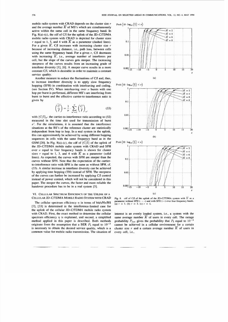
mobile radio system with CRAD depends on the cluster size T
and the average numberr of MS's which are simultaneously
active within the same cell in the same frequency band. In
Fig. S(a)-(c), the cdf of C/I for the uplink of the JD-CDDMA
mobile radio system with C U D s depicted for cluster sizes
T equal to 1, 3 , and 4 with as a parameter (dashed lines).
For a given r, /I increases with increasing cluster size T
because of increasing distance, i.e., path loss, between cells
using the same frequency band. For a given T , C/I decreaseswith increasing K, .e., average number of interferers per
cell, but the slope of the curves gets steeper. The increasing
steepness of the curves results from an increasing grade of
interferer diversity [l], [6]. A steeper curve results in a more
constant C/I, which is desirable in order to maintain a constant
service quality.
Another measure to reduce the fluctuations of C/I and, thus,
to increase interferer diversity is to apply slow frequency
hopping (SFH) in combination with interleaving and coding,
(see Section IV). When interleaving over U bursts with one
hop per burst is performed, different MS's are interfering from
burst to burst and the effective carrier-to-interference ratio is
given by
(7)1. 2(4)u'=l U'
(33)
with ( C / I ) v ~he carrier-to-interference ratio according to (32)
measured in the time slot used for transmission of burst
U'. For the simulations, it is assumed that the interference
situations at the BS's of the reference cluster are statistically
independent from hop to hop. In a real system in the uplink,
this can approximately be achieved by using different hopping
sequences in cells with the same frequeEy band as in the
GS M [20]. In Fig. S(a)-(c), the cdf of (C/ I ) of the uplink of
the JD-C/TDMA mobile radio system with CRAD and SFH
over U equal to four frequency bands is shown for cluster
sizes T equal to 1, 3, and 4 with K as a parameter (solid
lines). As expected, the curves with SFH are steeper than thecurves without SFH. Note that the expectation of the carrier-
to-interference ratio with SFH is the same as without SFH, cf.
(33). A similar increase in interferer diversity can be achieved
by applying time hopping (TH) instead of SFH. The steepness
of the curves can further be increased by applying C/I control
instead of power control, which will not be considered in this
paper. The steeper the curves, the faster and more reliable the
handover procedure has to be in a real system [ 5 ] .
VI . CELLULAR SPECTRUM EFFICIENCYF TH E UPLINK OF A
CELLULARD-CR DMA MOBILE ADIOSYSTEM WITH CRAD
The cellular spectrum efficiency Q in terms of bit/s/Hz/BS
[7], [33] is determined in the interference-limited case for
the uplink of the cellular JD-CDDMA mobile radio system
with CRAD. First, the exact method to determine the cellular
spectrum efficiency Q is explained, and second, a simplified
method applied in this paper is described. Both methods
originate from the assumption that a BER Pb equal to
is necessary to obtain the desired service quality, which is a
common value for mobile radio transmission. The situation of
Prob (10 . og,, (F) <z)
1
0.1
0.01
0.0oj-15 -10 -5 0 5 10 15 0
X
-10 -5 0 5 10 15 20
X
(b)
Prob (10' log,, ( y ) <z)
-10 -5 0 5 10 15 20
X
(C)
Fig. 8. cd f of C/l of the uplink o f the J D - C W M A system with I; s aparameter without SFH (- - ) and with SFH (-) over four frequency bands.(a) T = 1. (b) r = 3 . ( c ) T =4.
interest is an evenly loaded system, i.e., a system with the
same average number of users in every cell. The outage
probability Pout ives the probability that Pb equal to l o p 3cannot be achieved in a cellular environment for a certain
cluster size T and a certain average number K of users in
every cell, i.e.,

7/27/2019 Hybrid CTDMA
http://slidepdf.com/reader/full/hybrid-ctdma 10/12
7/27/2019 Hybrid CTDMA
http://slidepdf.com/reader/full/hybrid-ctdma 11/12
~
578 IEEE JOURNAL ON SELECTED AREAS IN COMMUNICATIONS, VOL. 12, NO. 4, MAY 1994
q / b i t / s /H z /WS )
(a)
.05 . I .15 .2 .25 . 3
7 / b i t / s /H z /WS )
(b)
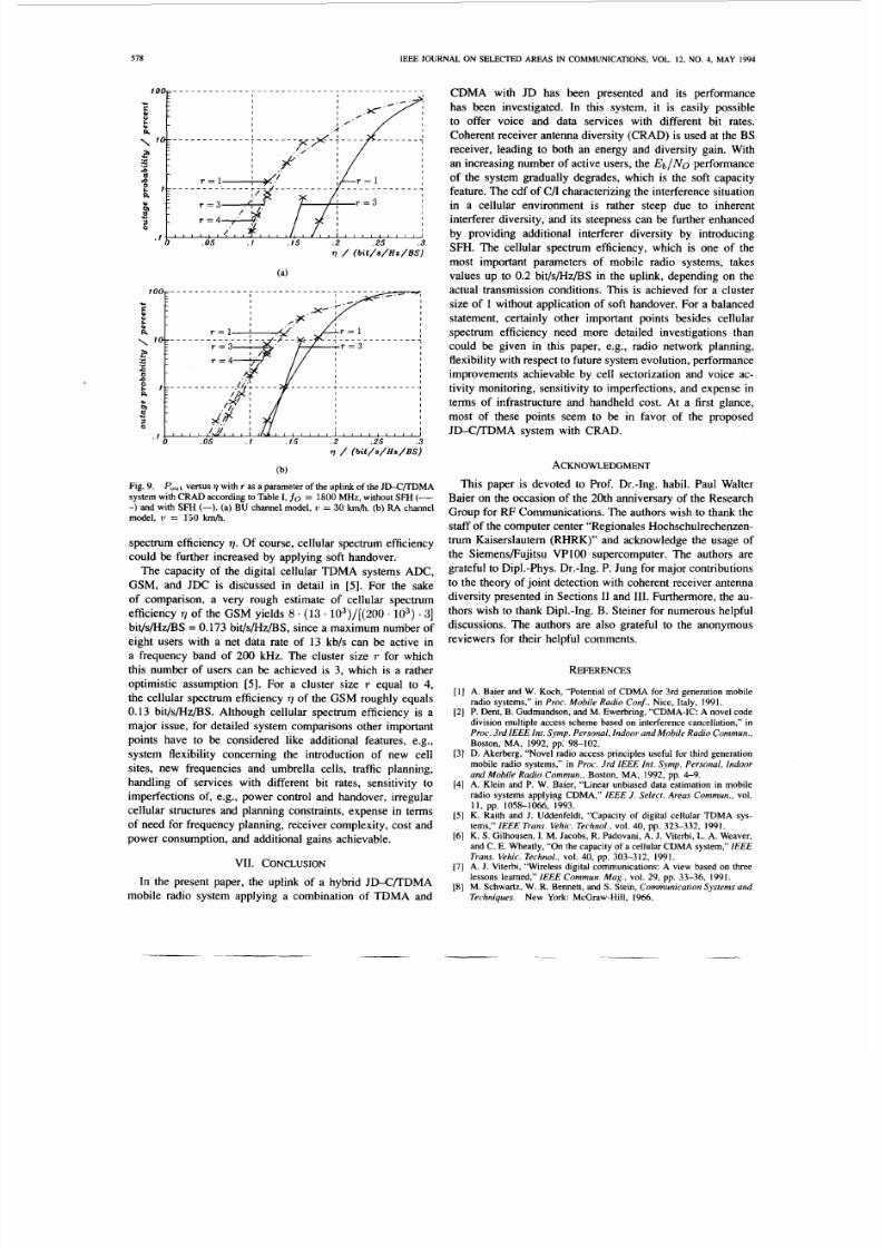
Fig. 9. Pout ersus 9with T as a parameter of the uplink of the JD-C/TDM Asystem with CR AD according to Table I, fo =1800 MHz, without SFH-) and with SFH (-). (a) BU channel model, ti =30 kmh. (b) RA channelmodel, t i = 150 kmh.
spectrum efficiency 7.Of course, cellular spectrum efficiency
could be further increased by applying soft handover.
The capacity of the digital cellular TDMA systems ADC,
GSM, and JDC is discussed in detail in [ 5 ] . For the sake
of comparison, a very rough estimate of cellular spectrum
efficiency 7 of the GSM yields 8 . 1 3 .103) / [ (200 . lo3) . 3 ]bit/s/Hz/BS =0.173 bit/s/Hz/BS, since a maximum number of
eight users with a net data rate of 13 kb/s can be active in
a frequency band of 200 kHz. The cluster size T for which
this number of users can be achieved is 3, which is a rather
optimistic assumption [ 5 ] . For a cluster size T equal to 4,
the cellular spectrum efficiency 7 of the GSM roughly equals
0.13 bit/s/Hz/BS. Although cellular spectrum efficiency is a
major issue, for detailed system comparisons other important
points have to be considered like additional features, e.g.,
system flexibility concerning the introduction of new cell
sites, new frequencies and umbrella cells, traffic planning,
handling of services with different bit rates, sensitivity to
imperfections of, e.g., power control and handover, irregular
cellular structures and planning constraints, expense in terms
of need for frequency planning, receiver complexity, cost and
power consumption, and additional gains achievable.
VII. CONCLUSION
In the present paper, the uplink of a hybrid JD-CRDMA
mobile radio system applying a combination of TDMA and
CDMA with JD has been presented and its performance
has been investigated. In this system, it is easily possible
to offer voice and data services with different bit rates.
Coherent receiver antenna diversity (CRAD) is used at the BS
receiver, leading to both an energy and diversity gain. With
an increasing number of active users, the & / N O performance
of the system gradually degrades, which is the soft capacity
feature. The cdf of C/I characterizing the interference situation
in a cellular environment is rather steep due to inherentinterferer diversity, and its steepness can be further enhanced
by providing additional interferer diversity by introducing
SFH. The cellular spectrum efficiency, which is one of the
most important parameters of mobile radio systems, takes
values up to 0.2 bit/s/Hz/BS in the uplink, depending on the
actual transmission conditions. This is achieved for a cluster
size of 1 without application of soft handover. For a balanced
statement, certainly other important points besides cellular
spectrum efficiency need more detailed investigations than
could be given in this paper, e.g., radio network planning,
flexibility with respect to future system evolution, performance
improvements achievable by cell sectorization and voice ac-
tivity monitoring, sensitivity to imperfections, and expense in
terms of infrastructure and handheld cost. At a first glance,
most of these points seem to be in favor of the proposed
JD-C/TDMA system with CRAD.
ACKNOWLEDGMENT
This paper is devoted to Prof. Dr.-Ing. habil. Paul Walter
Baier on the occasion of the 20th anniversary of the Research
Group for RF Communications. The authors wish to thank the
staff of the computer center “Regionales Hochschulrechenzen-
trum Kaiserslautern (RHRK)” and acknowledge the usage of
the SiemensFujitsu VPlOO supercomputer. The authors are
grateful to Dip1.-Phys. Dr.-Ing. P. Jung for major contributions
to the theory of joint detection with coherent receiver antenna
diversity presented in Sections I1 and 111. Furthermore, the au-
thors wish to thank Dip1.-Ing. B. Steiner for numerous helpfuldiscussions. The authors are also grateful to the anonymous
reviewers for their helpful comments.
REFERENCES
A. Baier and W. Koch, “Potential of CDMA for 3rd generation mobileradio systems,” in Proc. Mobile Radio Con&,Nice, Italy, 1991.P. Dent, B. Gu dmundson, and M. Ewerbring, “CDM A-IC: A novel cod edivision multiple access scheme based on interference cancellation,” inProc. 3rd IEEE Int. Symp. Personal, Indoor and Mobile Radio Com mun.,Boston, MA, 1992, pp. 98-102.D. Akerberg, “Novel radio access principles useful for third generationmobile radio systems,” in Proc. 3rd IEEE Int. Symp. Personal, Indoor
and Mobile Radio Commun., Boston, MA, 1992, pp. 4-9.A. Klein and P. W. Baier, “Linear unbiased data estimation in mobileradio systems applying CDMA,” IEEE J . Select. Areas Comm un., vol.
K. Raith and J. Uddenfeldt, “Capacity of digital cellular TDMA sys-tems,” IEEE Trans. Vehic. Terhnol., vol. 40, pp. 323-332, 1991.K. S. Gilhousen, I. M. Jacobs, R. Padovani, A. J. Viterbi, L. A . Weaver,and C. E. Wbeatly, “On the capacity of a cellular CDMA system,” IEEE
Trans. Vehic. Technol., vol. 40, pp. 303-312, 1991.A. J. Viterbi, “Wireless digital communications: A view based on threelessons learned,” IEEE Commun. Mag., vol. 29, pp. 33-36, 1991.M . Schwartz, W . R. Bennett, and S . Stein, Communication System s and
Techniques. New York: McGraw-Hill, 1966.
1 1 , pp. 1058-1066, 1993.

7/27/2019 Hybrid CTDMA
http://slidepdf.com/reader/full/hybrid-ctdma 12/12
BLANZ er al.: CELLULAR HYBRID CEDMA MOBILE RADIO SYSTEM 579
R. Kohno, H. Imai, M. Hatori, and S . Pasupathy, “Combination ofan adaptive array antenna and a canceller of interference for direct-seque nce spread-spectrum multiple-access system,” IEEE J. Select.
Areas Commun., vol. 8, pp. 675-682, 1990.S. Kubota, S . Kato, and K. Feher, “Inter-channel interference cancella-tion technique for CDMA mobile/personal communication systems,” inProc. 3rd IEEE Int. Symp. Personal, Indoor and Mobile Radio Com mun.,
Boston, MA, 1992, pp. 112-117.A. J. Viterbi, “Very low rate convolutional codes for maximum theoreti-
cal performance of spread-spectrum multiple-access channels,” IEEE J.
Select. Areas Commun., vol. 8, pp. 641-649, 1990.Y. C. Yoon, R. Kohno, and H. Imai, “A spread-spectrum multi-
access system with a cascade of cochannel interference cancellersfor multipath fading channels,” in Proc. 2nd IEEE Int. Symp. Spread
Spectrum Techniques and Applications, Yokohama, Japan, 1992, pp.
S . Mowbray, R. D. F’ringle, and P. M. Grant, “Increased CDMAsystem capacity through adaptive cochannel noise regeneration andcancellation,” IEE Proc., pt. I, vol. 193, pp. 515-524, 1992.S. Verdu, “Minimum probability of error for asynchronous Gaussianmultiple-access channels,” IEEE Trans. Inform. Theory, vol. 32, pp.
R. Lupas and S. Verdu, “Linear multiuser detectors for synchronouscode-division multiple-access channels,” IEEE Trans. Inform. Theory,
2. Xie, R. T. Short, and C. K. Rushforth, “A family of suboptimumdetectors for coherent multiuser communications,” IEEE J. Select Areas
Commun., vol. 8, pp. 683-690, 1990.A. Kajiwara and M. Nakagawa, “Crosscorrelation cancellation in SS/DSblock demodulator,” IEICE Trans., vol. E 74, pp. 2596-2602, 1991.
P. Jung, J. Blanz, and P. W. Baier, “Coherent receiver antenna diversityfor CDMA mobile radio systems using joint detection,” in Proc.
4th IEEE Int. Symp. Personal, Indoor and Mobile Radio Comm un.,Yokohama, Japan, 1993, pp. 488492.M. NaRhan, P. Jung, A. Steil, and P. W. Baier, “On the effects ofquantization, nonlinear amplification and band-limitation in CDMAmobile radio systems using joint detection,” in Proc. Wireless Commun.
C o n j , Calgary, 1993, pp. 173-186.CEPT/CCH/GSM Recommend. Series 1-11.F. Adachi, M. T. Feeney, A. G. Williamson, and J. D. Parsons,“Crosscorrelation between the envelopes of 900 MHz signals received
at a mobile radio base station site,” IEE Proc., Pt. F, vol. 133, pp.506-512, 1986.B. Steiner and P. W. Baier, “Low cost channel estimation in the uplinkreceiver of CDMA mobile radio systems,” Frequenz., vol. 47, pp.292-298, 1993.X. Lasne, C. Baroux, and G. Kawas Kaleh, “Joint reception of multi-user data for synchr onous code-division multiple access,” in Proc. COST231 TD(92)85, Helsinki, Finland, 1992.
A. Papoulis, Probability, Random Variables, and Stochastic Processes.New York: McGraw-Hill, 1984.A. D. Whalen, Detection ofSignals in Noise. New York: Academic,1971.K. Brammer and G. SitHing, Kalman-Bury-Filter - DeterministischeBeobachtungen und stochastische Filterung. Munich: Oldenbourg,1975.S . W. Marple, Digital Spectral Analysis with Applications. EnglewoodCliffs, NJ: Prentice Hall, 1987.P. Hoher, “A statistical discrete-time model for the WSSUS multipathchannel,” IEEE Trans. Vehic. Technol., vol. 41, pp. 461468. 1992.COST 207, Digital Land Mobile Radio Com munications. Final Re-
port . Luxembourgh: Office for Official Publications of the EuropeanCommunities, 1989.B. Steiner, M. NaRhan, P. Jung, and P. W. Baier, “Ein Konzept
der Kanalschatzung, Inte rferen zelimin ierng und Leistungsregelung furCDMA-Mobilfunksysteme,” in Proc. ITG-Fachtagung “Mob ile Kom -munikation,” Neu-Ulm, 1993, pp. 77-88.P. Jung and P. W. Baier, “On the re presentation of CPM signals by linearsuperposition of impulse s in the bandpass domain,” IEEE J. Select. Areas
Commun., vol. 10, pp. 12361242, 1992.J. Walfisch and H. L. Bertoni, “A theoretical model of UHF propagationin urban environments,” IEEE Trans. Antennas and Propag at., vol. 36,pp. 1788-1 796, 1988.W. C. Y. Lee, “Spectrum efficiency in cellular,” IEEE Trans. Vehic.
Technol., vol. 38, pp. 69-75, 1989.
87-90.
85-96, 1986.
vol. 35, pp. 123-136, 1989.
[34] W. an Etten, “Maximum likelihood receiver for multiple channeltransmission systems,’’ IEEE Trans. Commun., vol. 24, pp. 276-283,1976.
[35] A. Baier, “Multirate DS-CDMA: A promising access technique for
third-generation mobile radio systems,’’ in Proc. 4th IEEE Int. Symp.
Person al, Indoor, and Mobile Radio Commun., Yokahama, Japan, 1993,pp. 114-118.
[36] A. Radovic and B. Aazhang, “Iterative algorith ms for joint data detectionand delay estimation for code division multiple access communication
systems,” in Proc. 31st Ann. Allerton Con5 Commun., Control and
Computing, Univ. Illinois at Urbana-Champaign, 1993.[37] W. Sauer-Greff and R. A. Kennedy , “Suboptimal ML SE for distortedmultiple-access channels using the M-algorithm,” in Proc. AachenerKolloquium Signaltheorie, Aachen, Germany, 1994, pp. 267-270.
ests are in the field of
Josef Blanz was bom in Kaiserslautem, Germany,in 1967. He received the Dipl-Ing. degree in elec-trical engineering from the University of Kaiser-slautem in 1993.
During 1990-1992, he freelanced with the Mi-croelectronics Centre of the University of Kaiser-slautem, where he was engaged in the design of
digital circuits with field programmable gate arrays.In March 1993, he joined the Research Group forR FCommunications of the University of Kaiserslauternas a Research Assistant. His present research inter-
antenna diversity techniques for mobile radio systems.
Anja Klein (S’93) was bom in Kaiserslautem, Ger-many, in 1967. She received the Dip1.-Ing. degreein electrical engineering from the University ofKaiserslautern in 1991.
Since then, she has been a Research Assistantwith the Research Group for RF Communicationsof the University of Kaiserslautem. Her researchinterests are mainly concentrated on mobile radiocommunications and estimation theory.
Markus NaRh an was born in Zweibriicken, Ger-
many, in 1965. He received the Dip1.-Ing. degreein electrical engineering from the University ofKaiserslautem in 1992.
Since then, he has been a Research Assistant withthe Research Group for RF Communications of theUniversity of Kaiserslautem. His research interestsare mainly concentrated on simulation techniquesand multiple access techniques for mobile radio
systems.
Andreas Steil was bom in Cochem, Germany, in1964. He received the Dipl.-Ing. degre e in electricalengineering from the University of Kaiserslautemin 1991.
Since then, he has been a Research Assistant
with the Research Group for RF Communicationsof the University of Kaiserslautem. His present re-search interests are mobile radio systems, especiallycellular aspects and spectral efficiency.