HVAC Controls
12
IIUM Engineering Journal, Vol. 6, No. 2, 2005 Mustafa et al 1 FUZZY LOGIC BASED CONTROLLER FOR MAINTAINING HUMAN COMFORT WITHIN INTELLIGENT BUILDING SYSTEM NASRODIN T. MUSTAPHA, MOMOH J. E. SALAMI, NAZIM M. NASIRI Department of Mechatronics Engineering, Kulliyyah of Engineering International Islamic University Malaysia, P.O. Box 10, 50728, Kuala Lumpur, Malaysia Abstract:This paper presents an intelligent control approach for air handling unit (AHU) which is an integral part of heat, ventilation, and air conditioning (HVAC) system. In the past years various control design for HVAC have been proposed as this system remarkably consumes very high energy. But most of the proposed designs were focused on the control flow of heat-transfer medium such as chilled or heated water while the importance of the efficient mixture of outdoor and indoor enthalpies is sometimes ignored. These enthalpies invariably determine the best strategy to overcome thermal load in a controlled environment to satisfy human comfort, hence a control design strategy must be able to efficiently regulate the flow and mixture of outdoor and indoor enthalpies by a proper control of AHU dampers and fans. This approach requires sensors to measure temperature and relative humidity of both outdoor and indoor environments. However, unpredictable level of disturbances coming from many sources including heat generated by occupants, electrical items and air leaking and the continuous changes of outdoor enthalpy makes it difficult to model the process. Consequently, conventional controllers are not suitable, hence the use of fuzzy logic controller (FLC) is proposed in this paper. This proposed controller operates in a master and slave control loop so as to control the AHU dampers and fans with adjustable output membership function whilst at the same time a scaling-factor method is used to drive the master operation. To implement the proposed system, a small scale prototype has been designed and fabricated. This prototype is an AHU model which consists of ductwork, temperature and humidity sensors, dampers, air cooling and heating systems. A small box is used as a conditioning space in which a room temperature is measured. The control algorithm is programmed using National Instrument (NI) LabVIEW and executed using NI FieldPoint. Experimental results reveal that proper control of AHU dampers and fans is an effective and practical means to satisfy human comfort with minimum energy consumption. Keywords: Human comfort, Intelligent control, Air handling unit, Adaptive fuzzy logic control 1. INTODUCTION Heat, Ventilation and Air Conditioning (HVAC) system has nowadays become an integral part of building services. This system comprises several subsystems such as the cooling and heating units, air handling unit (AHU), dedicated digital controllers (DDC)
-
Upload
nitin-gupta -
Category
Documents
-
view
237 -
download
3
description
HVAC controls are using through BMS and can be varied among the different zones of the system.
Transcript of HVAC Controls
IIUM Engineering Journal, Vol. 6, No. 2, 2005 Mustafa et al
1
FUZZY LOGIC BASED CONTROLLER FOR MAINTAINING HUMAN COMFORT WITHIN
INTELLIGENT BUILDING SYSTEM
NASRODIN T. MUSTAPHA, MOMOH J. E. SALAMI, NAZIM M. NASIRI
Department of Mechatronics Engineering, Kulliyyah of Engineering
International Islamic University Malaysia, P.O. Box 10, 50728, Kuala Lumpur, Malaysia
Abstract:This paper presents an intelligent control approach for air handling unit (AHU) which is an integral part of heat, ventilation, and air conditioning (HVAC) system. In the past years various control design for HVAC have been proposed as this system remarkably consumes very high energy. But most of the proposed designs were focused on the control flow of heat-transfer medium such as chilled or heated water while the importance of the efficient mixture of outdoor and indoor enthalpies is sometimes ignored. These enthalpies invariably determine the best strategy to overcome thermal load in a controlled environment to satisfy human comfort, hence a control design strategy must be able to efficiently regulate the flow and mixture of outdoor and indoor enthalpies by a proper control of AHU dampers and fans. This approach requires sensors to measure temperature and relative humidity of both outdoor and indoor environments. However, unpredictable level of disturbances coming from many sources including heat generated by occupants, electrical items and air leaking and the continuous changes of outdoor enthalpy makes it difficult to model the process. Consequently, conventional controllers are not suitable, hence the use of fuzzy logic controller (FLC) is proposed in this paper. This proposed controller operates in a master and slave control loop so as to control the AHU dampers and fans with adjustable output membership function whilst at the same time a scaling-factor method is used to drive the master operation. To implement the proposed system, a small scale prototype has been designed and fabricated. This prototype is an AHU model which consists of ductwork, temperature and humidity sensors, dampers, air cooling and heating systems. A small box is used as a conditioning space in which a room temperature is measured. The control algorithm is programmed using National Instrument (NI) LabVIEW and executed using NI FieldPoint. Experimental results reveal that proper control of AHU dampers and fans is an effective and practical means to satisfy human comfort with minimum energy consumption.
Keywords: Human comfort, Intelligent control, Air handling unit, Adaptive fuzzy logic control
1. INTODUCTION
Heat, Ventilation and Air Conditioning (HVAC) system has nowadays become an integral part of building services. This system comprises several subsystems such as the cooling and heating units, air handling unit (AHU), dedicated digital controllers (DDC)
IIUM Engineering Journal, Vol. 6, No. 2, 2005 Mustafa et al
2
and the list could continue. The main function of HVAC is to maintain indoor air quality and comfort level which are services that require high energy consumption. Many studies [1-10] have shown that about 50-70% of the energy is consumed for the above purposes. However, employing advance and more flexible control technique reduces energy consumption and optimize the performance of the HVAC regardless of thermal loads acting upon the system.
AHU plays the major task in mechanical regulation of the air coming in and out of the building; and the way the air is conditioned by cooling or heating. This unit is designed to cope with the wide range of the system operating condition as weather and building occupants’ activities change significantly and periodically from day to night and from season to season 1. Its primary function is achieved by having mixing dampers in the AHU properly modulated (position) as a function of the three main parameters namely the fluid energy or enthalpy (temperature and moisture) at the AHU discharge (supply air to the zones), outside and the return air. Maximizing indoor quality is a process of eliminating contaminants from the air and allowing appropriate amount of air moisture. This process also is handled by mixing dampers.
Positioning the dampers can be achieved by sending fixed signal to their actuators based on enthalpies measured as mentioned earlier. However, the magnitude of the fixed signal can only be useful with system whose mathematical representation could be formulated. In actual situation AHU cannot easily be modeled as it characterizes highly nonlinear system as result of continuous thermal load from various sources acting on both the conditioned space and the (AHU) unit. For this reason, conventional controller such as PID would not produce desirable results.
This paper proposes Fuzzy Logic Controller for air handling Unit. It is implemented by taking into accounts the temperatures of supply, outside, return and the mixed air to maintain a zone temperature at the presence of thermal load from various sources. Studies have suggested that if outside, supply and return air relative humidity variables are considered for an AHU control, better performance can be expected. However, having more inputs into the AHU controller will further complicate the systems computational task and thus will contribute to the degradation of the control performance. This is avoided by considering only the return and the supply relative humidity as they can sufficiently provide information on an account of moisture level required in the conditioned space.
To achieve the best performance of a controller, its parameters must be tuned. However, a system with a nonlinear operating environment cannot rely on a tuning alone as the changes in the process have a great effect in its performance. To overcome this problem an adaptive mechanism must be incorporated into an FLC design. Adaptive FLC is capable of updating its parameters against the changes in the process. This paper proposes the use of adaptive FLC which is implemented using scaling-factor method. The adaptive mechanism tunes the FLC by adjusting the universal discourse of the output membership function by a factor g0. This method maintains a good performance of the FLC.
IIUM Engineering Journal, Vol. 6, No. 2, 2005 Mustafa et al
3
2. SYSTEM DESCRIPTION
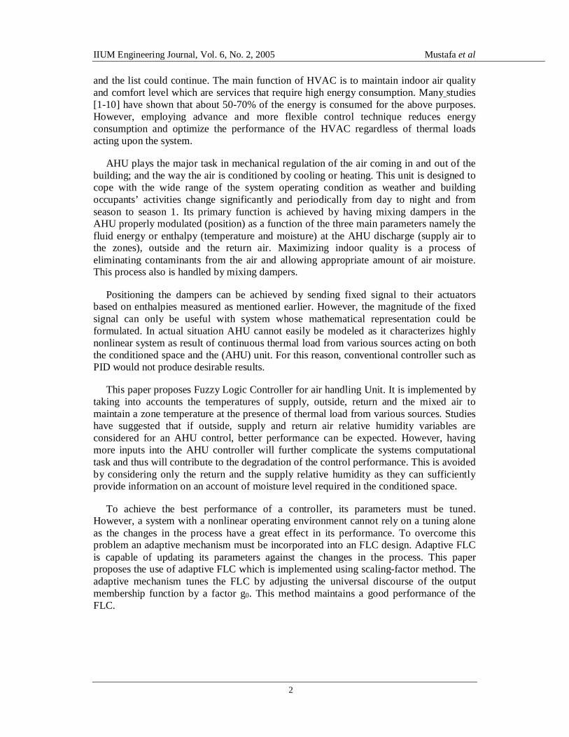
To implement the proposed system, AHU prototype is designed and fabricated as shown in Fig. 1. This prototype comprises four dampers actuated by DC motors, temperature and relative humidity sensors, cooling and heating unit, and fans. A cooling unit is linked to the AHU ductwork to supply cold air; and a heater is placed at the discharge point to speed up heating process when required. Small box is constructed as a conditioning space where room temperature is measured. This temperature is the reference for all actuating signals as function of the outdoor and indoor enthalpies (temperature + relative humidity). Indoor temperature is the variable that is being controlled by properly modulating the mixing dampers OAD, EAD, and RAD and fans SAF and RAF shown Fig. 2. There are times where the outside air is more economical to condition than the return air. During this period an economizer control mode is enabled in which fans and cooling equipments are turned off.
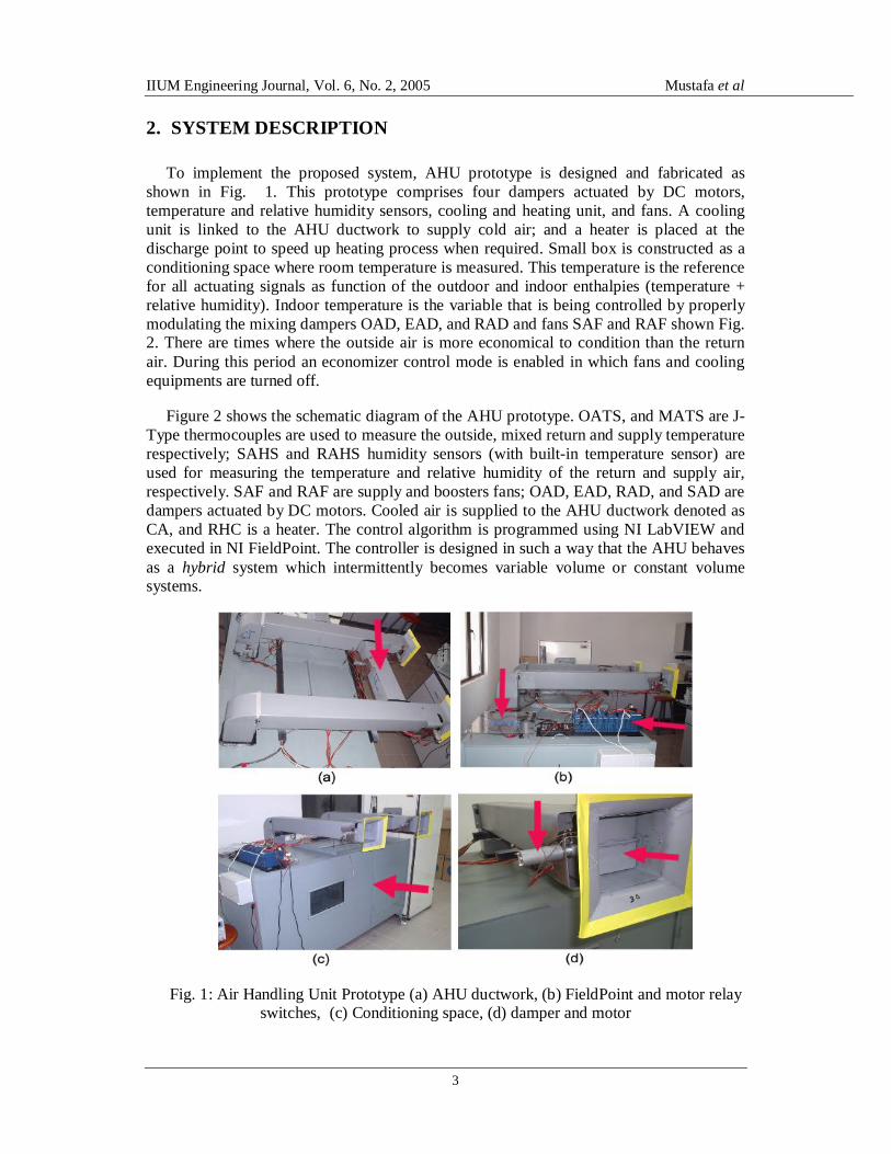
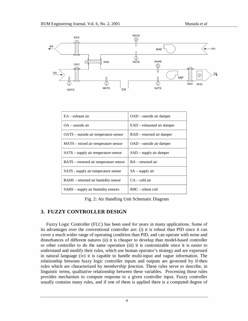
Figure 2 shows the schematic diagram of the AHU prototype. OATS, and MATS are J-Type thermocouples are used to measure the outside, mixed return and supply temperature respectively; SAHS and RAHS humidity sensors (with built-in temperature sensor) are used for measuring the temperature and relative humidity of the return and supply air, respectively. SAF and RAF are supply and boosters fans; OAD, EAD, RAD, and SAD are dampers actuated by DC motors. Cooled air is supplied to the AHU ductwork denoted as CA, and RHC is a heater. The control algorithm is programmed using NI LabVIEW and executed in NI FieldPoint. The controller is designed in such a way that the AHU behaves as a hybrid system which intermittently becomes variable volume or constant volume systems.
Fig. 1: Air Handling Unit Prototype (a) AHU ductwork, (b) FieldPoint and motor relay switches, (c) Conditioning space, (d) damper and motor
IIUM Engineering Journal, Vol. 6, No. 2, 2005 Mustafa et al
4
SAF
RAF
EA – exhaust air OAD – outside air damper
OA – outside air EAD – exhausted air damper
OATS – outside air temperature sensor RAD – returned air damper
MATS – mixed air temperature sensor OAD – outside air damper
SATS – supply air temperature sensor SAD – supply air damper
RATS – returned air temperature sensor RA – returned air
SATS - supply air temperature sensor SA – supply air
RAHS – returned air humidity sensor CA – cold air
SAHS – supply air humidity sensors RHC – reheat coil
Fig. 2: Air Handling Unit Schematic Diagram
3. FUZZY CONTROLLER DESIGN
Fuzzy Logic Controller (FLC) has been used for years in many applications. Some of its advantages over the conventional controller are: (i) it is robust than PID since it can cover a much wider range of operating condition than PID, and can operate with noise and disturbances of different natures (ii) it is cheaper to develop than model-based controller or other controller to do the same operation (iii) it is customizable since it is easier to understand and modify their rules, which use human operator’s strategy and are expressed in natural language (iv) it is capable to handle multi-input and vague information. The relationship between fuzzy logic controller inputs and outputs are governed by if-then rules which are characterized by membership function. These rules serve to describe, in linguistic terms, qualitative relationship between these variables. Processing those rules provides mechanism to compute response to a given controller input. Fuzzy controller usually contains many rules, and if one of them is applied there is a computed degree of
IIUM Engineering Journal, Vol. 6, No. 2, 2005 Mustafa et al
5
match between crisp input and the fuzzy sets, which describe the meaning of the antecedent part of the rules, and then ‘clipping’ the fuzzy set describing the meaning of the consequent part of the rule, to the degree to which the antecedent part has been matched by the crisp input.
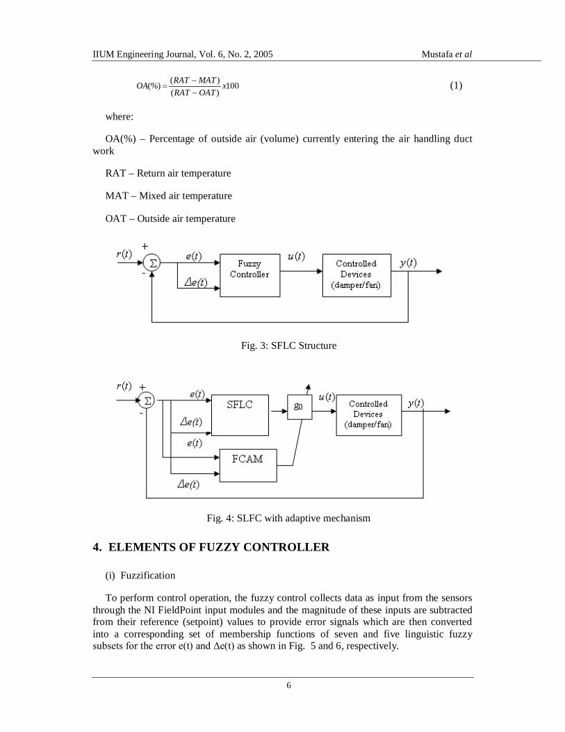
The proposed fuzzy logic controller has two components namely slave and master components. The slave fuzzy logic controller (SFLC) consists of six fuzzy control loops intermediately controlling four dampers and two fans. The SFLCs are two-input single-output controllers. The inputs are the temperature setpoint error, e(t), and the rate of change of this error, Δe(t), and the output, u(t), is damper position or fan speed, see Fig. 3. The initial rules and input/output membership functions of these controllers are heuristically created and is established based on observation made to capture the behavior of the system. Since this approach can be used only for approximating the process identification, we need to iteratively tune the SFLC during the design stage which is subject to stability analysis criteria using Lyapunov method 10. This tuning process has been carried out manually based on the observation of the system performance such as rise time, overshoot and steady state. The center and slopes of the input membership functions in each region is adjusted so that the corresponding rule provides an appropriate control action. There is need to modify the output membership function as well to adjust the rules governing the output universe of discourse. After the tuning is done, the initial FLC parameters namely the input and output membership functions, and the rules are established. Nonlinearity is caused by the effect of process dynamics and induced disturbances into the system. The performance of a well-tuned controller degrades when this problem is encountered and therefore the controller must be kept tuned at all the time to adapt to the changes in the process. To overcome this problem an adaptive fuzzy controller is proposed. This is implemented by tuning the output membership functions using scaling-factor method 11. This method is implemented by introducing gain g0 between the fuzzy controller and the controlled devices (dampers and fans). The structure of this fuzzy controller is shown in Fig. 4 where fuzzy control adaptive mechanism (FCAM) is the master component that adjusts the gain factor g0. The value of this gain is equal to 1 for the original choice of the membership function and therefore when the value of this gain changes is not equal to one the value of control signal instantaneously changes. With the presence of various sources of thermal load in the conditioned space as well as in the AHU itself, the controller provides appropriate command signal to the damper motors and the fans for a desirable system response. But since the system is nonlinear in nature the input-output relationship of the controller must be updated all the time. This is achievable using the adaptive mechanism FCAM. The main objective is to optimize the cooling or heating process by a proper mixture of fresh and return air. When the room temperature exceeds a threshold, the mixing dampers and fans are modulated in order to keep the temperature close to its setpoint without sacrificing the required relative humidity level. When the outside air temperature is lower than the return air temperature, it is more economical to condition the outside air and invariably cooling unit reduces its cooling load hence energy usage is lowered. Consequently, this approach makes use of the temperatures of the outside, mixed, return and supply air as the parameters to use for the cooling/heating process control. The required amount of outside air entering the air handling unit depends on the three components namely the outside air, return and mixed air temperatures. This amount is expressed in percentage:
IIUM Engineering Journal, Vol. 6, No. 2, 2005 Mustafa et al
6
100)()((%) x
OATRATMATRATOA
(1)
where:
OA(%) – Percentage of outside air (volume) currently entering the air handling duct work
RAT – Return air temperature
MAT – Mixed air temperature
OAT – Outside air temperature
Fig. 3: SFLC Structure
Fig. 4: SLFC with adaptive mechanism
4. ELEMENTS OF FUZZY CONTROLLER
(i) Fuzzification
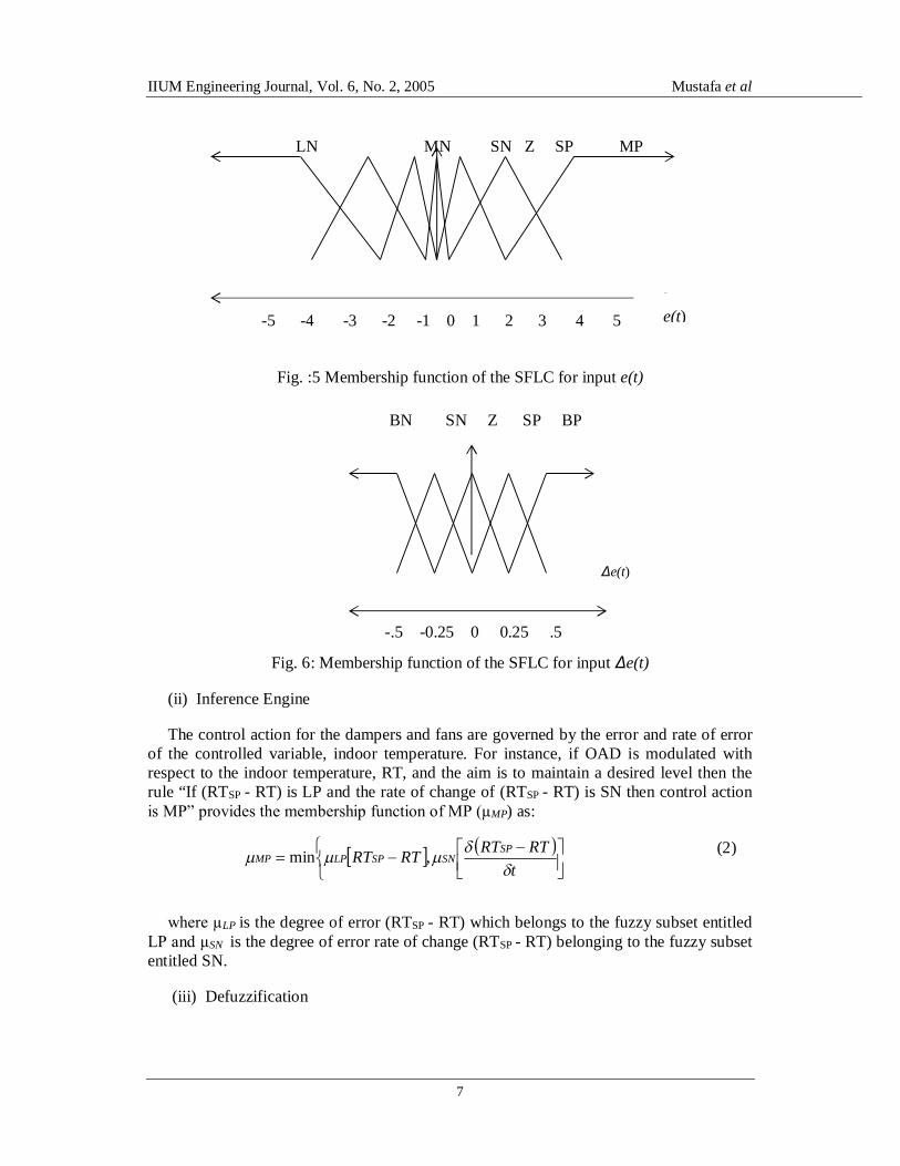
To perform control operation, the fuzzy control collects data as input from the sensors through the NI FieldPoint input modules and the magnitude of these inputs are subtracted from their reference (setpoint) values to provide error signals which are then converted into a corresponding set of membership functions of seven and five linguistic fuzzy subsets for the error e(t) and Δe(t) as shown in Fig. 5 and 6, respectively.
IIUM Engineering Journal, Vol. 6, No. 2, 2005 Mustafa et al
7
Fig. :5 Membership function of the SFLC for input e(t)
Fig. 6: Membership function of the SFLC for input Δe(t)
(ii) Inference Engine
The control action for the dampers and fans are governed by the error and rate of error of the controlled variable, indoor temperature. For instance, if OAD is modulated with respect to the indoor temperature, RT, and the aim is to maintain a desired level then the rule “If (RTSP - RT) is LP and the rate of change of (RTSP - RT) is SN then control action is MP” provides the membership function of MP (µMP) as:
(2)
where µLP is the degree of error (RTSP - RT) which belongs to the fuzzy subset entitled LP and µSN is the degree of error rate of change (RTSP - RT) belonging to the fuzzy subset entitled SN.
(iii) Defuzzification
LN MN SN Z SP MP
-5 -4 -3 -2 -1 0 1 2 3 4 5 e(t)
Δe(t)
-.5 -0.25 0 0.25 .5
BN SN Z SP BP
t
RTRTRTRT SPSNSPLPMP
,min
IIUM Engineering Journal, Vol. 6, No. 2, 2005 Mustafa et al
8
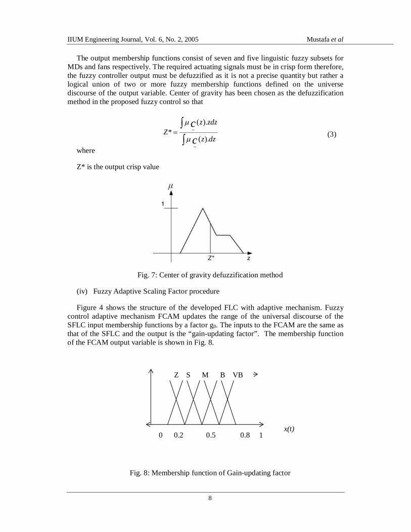
The output membership functions consist of seven and five linguistic fuzzy subsets for MDs and fans respectively. The required actuating signals must be in crisp form therefore, the fuzzy controller output must be defuzzified as it is not a precise quantity but rather a logical union of two or more fuzzy membership functions defined on the universe discourse of the output variable. Center of gravity has been chosen as the defuzzification method in the proposed fuzzy control so that
(3)
where
Z* is the output crisp value
Fig. 7: Center of gravity defuzzification method
(iv) Fuzzy Adaptive Scaling Factor procedure
Figure 4 shows the structure of the developed FLC with adaptive mechanism. Fuzzy control adaptive mechanism FCAM updates the range of the universal discourse of the SFLC input membership functions by a factor g0. The inputs to the FCAM are the same as that of the SFLC and the output is the “gain-updating factor”. The membership function of the FCAM output variable is shown in Fig. 8.
Fig. 8: Membership function of Gain-updating factor
x(t) 0 0.2 0.5 0.8 1
Z S M B VB
dzz
zdzzZ
cc
).(
).(*
~
~
IIUM Engineering Journal, Vol. 6, No. 2, 2005 Mustafa et al
9
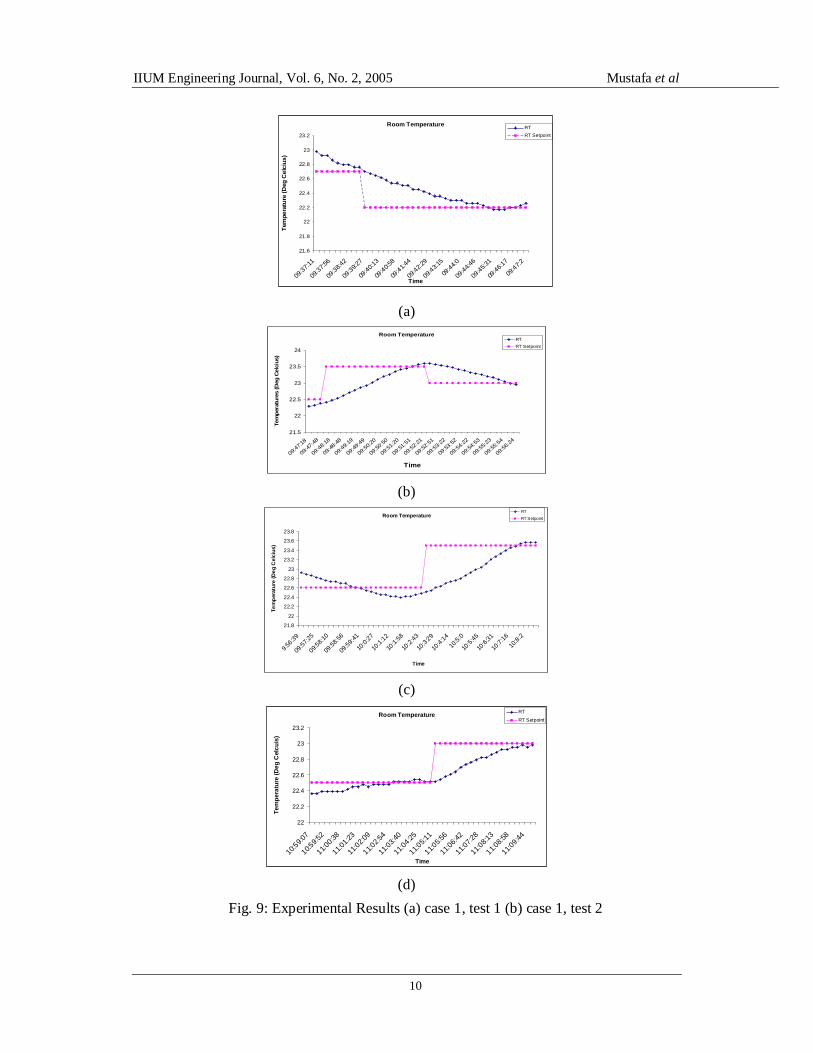
5. EXPERIMENTAL RESULTS AND ANALYSIS
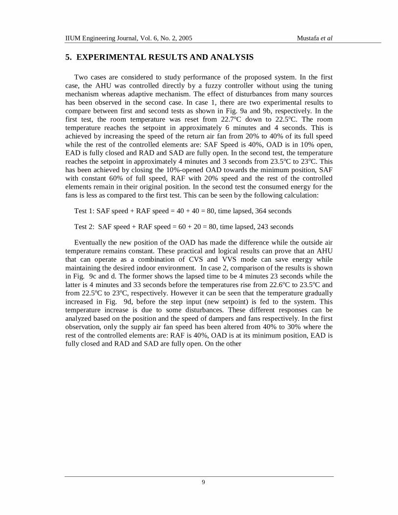
Two cases are considered to study performance of the proposed system. In the first case, the AHU was controlled directly by a fuzzy controller without using the tuning mechanism whereas adaptive mechanism. The effect of disturbances from many sources has been observed in the second case. In case 1, there are two experimental results to compare between first and second tests as shown in Fig. 9a and 9b, respectively. In the first test, the room temperature was reset from 22.7oC down to 22.5oC. The room temperature reaches the setpoint in approximately 6 minutes and 4 seconds. This is achieved by increasing the speed of the return air fan from 20% to 40% of its full speed while the rest of the controlled elements are: SAF Speed is 40%, OAD is in 10% open, EAD is fully closed and RAD and SAD are fully open. In the second test, the temperature reaches the setpoint in approximately 4 minutes and 3 seconds from 23.5oC to 23oC. This has been achieved by closing the 10%-opened OAD towards the minimum position, SAF with constant 60% of full speed, RAF with 20% speed and the rest of the controlled elements remain in their original position. In the second test the consumed energy for the fans is less as compared to the first test. This can be seen by the following calculation:
Test 1: SAF speed + RAF speed = 40 + 40 = 80, time lapsed, 364 seconds
Test 2: SAF speed + RAF speed = 60 + 20 = 80, time lapsed, 243 seconds
Eventually the new position of the OAD has made the difference while the outside air temperature remains constant. These practical and logical results can prove that an AHU that can operate as a combination of CVS and VVS mode can save energy while maintaining the desired indoor environment. In case 2, comparison of the results is shown in Fig. 9c and d. The former shows the lapsed time to be 4 minutes 23 seconds while the latter is 4 minutes and 33 seconds before the temperatures rise from 22.6oC to 23.5oC and from 22.5oC to 23oC, respectively. However it can be seen that the temperature gradually increased in Fig. 9d, before the step input (new setpoint) is fed to the system. This temperature increase is due to some disturbances. These different responses can be analyzed based on the position and the speed of dampers and fans respectively. In the first observation, only the supply air fan speed has been altered from 40% to 30% where the rest of the controlled elements are: RAF is 40%, OAD is at its minimum position, EAD is fully closed and RAD and SAD are fully open. On the other
IIUM Engineering Journal, Vol. 6, No. 2, 2005 Mustafa et al
10
Room Temperature
21.6
21.8
22
22.2
22.4
22.6
22.8
23
23.2
09:3
7:11
09:3
7:56
09:3
8:42
09:3
9:27
09:4
0:13
09:4
0:58
09:4
1:44
09:4
2:29
09:4
3:15
09:4
4:0
09:4
4:46
09:4
5:31
09:4
6:17
09:4
7:2
TimeTe
mpe
ratu
re (D
eg C
elci
us)
RTRT Setpoint
(a) Room Temperature
21.5
22
22.5
23
23.5
24
09:4
7:18
09:4
7:48
09:4
8:18
09:4
8:48
09:4
9:19
09:4
9:49
09:5
0:20
09:5
0:50
09:5
1:20
09:5
1:51
09:5
2:21
09:5
2:51
09:5
3:22
09:5
3:52
09:5
4:22
09:5
4:53
09:5
5:23
09:5
5:54
09:5
6:24
Time
Tem
pera
ture
s (D
eg C
elci
us)
RTRT Setpoint
(b)
Room Temperature
21.8
22
22.2
22.4
22.6
22.8
23
23.2
23.4
23.6
23.8
9:56:3
9
09:5
7:25
09:5
8:10
09:5
8:56
09:5
9:41
10:0
:27
10:1
:12
10:1:
58
10:2
:43
10:3
:29
10:4
:14
10:5
:0
10:5
:45
10:6
:31
10:7
:16
10:8
:2
Time
Tem
pera
ture
(Deg
Cel
cius
)
RTRT Setpoint
(c)
Room Temperature
22
22.2
22.4
22.6
22.8
23
23.2
10:59:0
7
10:59:5
2
11:00:3
8
11:01
:23
11:02:0
9
11:02:5
4
11:03
:40
11:04
:25
11:05:1
1
11:05:5
6
11:06
:42
11:07
:28
11:08:1
3
11:08:5
8
11:09
:44
Time
Tem
pera
ture
(Deg
Cel
cuis
)
RTRT Setpoint
(d)
Fig. 9: Experimental Results (a) case 1, test 1 (b) case 1, test 2
IIUM Engineering Journal, Vol. 6, No. 2, 2005 Mustafa et al
11
(c) case 2, test 1 (d) case 2, test 2
RELATIVE HUMIDITIES
0
10
20
30
40
50
60
70
9:56:39
09:5
7:25
09:5
8:10
09:5
8:56
09:5
9:41
10:0
:27
10:1
:12
10:1
:58
10:2
:43
10:3
:29
10:4
:14
10:5
:0
10:5
:45
10:6
:31
10:7
:16
10:8
:2
Time
SA
_RH
& R
A_R
H
SA_RH
RA_RH
Relative Humidities
0
10
20
30
40
50
60
70
10:59:0
7
10:59:5
2
11:00:3
8
11:01:2
3
11:02:0
9
11:02
:54
11:03:4
0
11:04
:25
11:05:1
1
11:05
:56
11:06:4
2
11:07
:28
11:08:1
3
11:08
:58
11:09:4
4
Time
Rel
ativ
e H
umid
ities
SA_RHRA_RH
(a) (b)
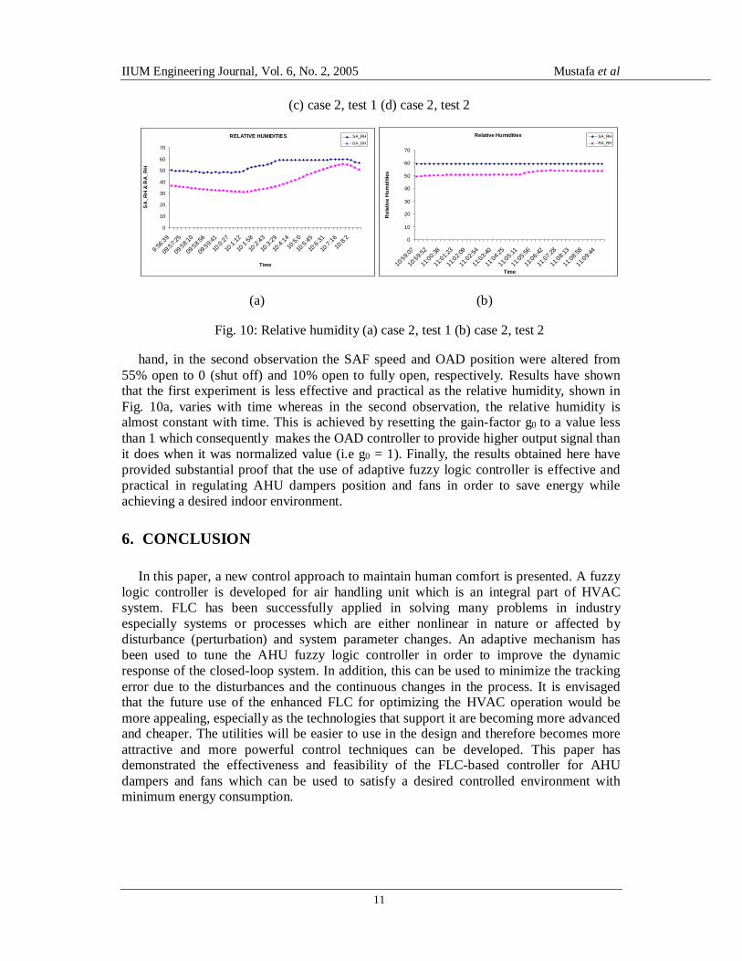
Fig. 10: Relative humidity (a) case 2, test 1 (b) case 2, test 2
hand, in the second observation the SAF speed and OAD position were altered from 55% open to 0 (shut off) and 10% open to fully open, respectively. Results have shown that the first experiment is less effective and practical as the relative humidity, shown in Fig. 10a, varies with time whereas in the second observation, the relative humidity is almost constant with time. This is achieved by resetting the gain-factor g0 to a value less than 1 which consequently makes the OAD controller to provide higher output signal than it does when it was normalized value (i.e g0 = 1). Finally, the results obtained here have provided substantial proof that the use of adaptive fuzzy logic controller is effective and practical in regulating AHU dampers position and fans in order to save energy while achieving a desired indoor environment.
6. CONCLUSION
In this paper, a new control approach to maintain human comfort is presented. A fuzzy logic controller is developed for air handling unit which is an integral part of HVAC system. FLC has been successfully applied in solving many problems in industry especially systems or processes which are either nonlinear in nature or affected by disturbance (perturbation) and system parameter changes. An adaptive mechanism has been used to tune the AHU fuzzy logic controller in order to improve the dynamic response of the closed-loop system. In addition, this can be used to minimize the tracking error due to the disturbances and the continuous changes in the process. It is envisaged that the future use of the enhanced FLC for optimizing the HVAC operation would be more appealing, especially as the technologies that support it are becoming more advanced and cheaper. The utilities will be easier to use in the design and therefore becomes more attractive and more powerful control techniques can be developed. This paper has demonstrated the effectiveness and feasibility of the FLC-based controller for AHU dampers and fans which can be used to satisfy a desired controlled environment with minimum energy consumption.
IIUM Engineering Journal, Vol. 6, No. 2, 2005 Mustafa et al
12
REFERENCES
[1] P.Y Guo, Z.H.Guang, Z. Bein, Y.G. Taejon, “A Simple Fuzzy Adaptive Control Method and Application in HVAC”, IEEE, 1998
[2] J.S.R Jang, C.T. Sun, E. Mizutani, “ Neuro-Fuzzy and Soft Computing’, Pentice-Hall, Inc. 1997.
[3] H.B Verbruggen, H.-J. Zimmermann, R. Babuska, “Fuzzy Algorithms for Control”, Kluwer Academic Publisher, 1999
[4] T.Y Sun, “Air Handling System Design”, McGraw-Hill, Inc. 1994. [5] F.C. McQuiton, E.D Parker, E.D Spiler, “Heating, Ventilating, and Air Conditioning, Analysis
and Design “, 5th Ed, John Wiley & Sons, 2000. [6] V. Bradshaw, “ Building Control System”, 2nd Ed, John Wiley & Sons, 1993. [7] T. Horan, “ Control Systems and Application for HVAC/R”, Prentice-Hall, Inc. 1997. [8] D.V. Chadderton, “Building Services Engineering”, 2nd Ed, E & FN Spon, 1998. [9] C,-T. Lin and C.S G. Lee, 1996, “ Neural Fuzzy Systems: A Neuro-Fuzzy Synergism to
intelligent Systems”, Prentice Hall. [10] K.M Passino, S. Yurkovich, “Fuzzy Control”, 1998, Addision Wesly Longman, Inc [11] L. Song and M. Liu, 2004, “Optimal Outside Airflow Control of an Integrated Air-Handling
Unit System for Large Office Buildings”, Journal of Solar Energy Engineering, Volume 126, Issue 1, pp. 614-619