
Hive Body 2 The Hive Bodies (Super) - Michigan bees hive body is the heart of a managed bee hive...
9
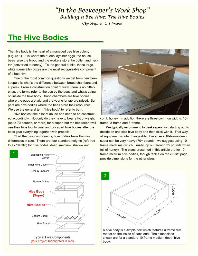
The hive body is the heart of a managed bee hive colony (Figure 1). It is where the queen lays her eggs, the house bees raise the brood and the workers store the pollen and nec- tar (converted to honey). To the general public, these large, white (generally) boxes are the most recognizable component of a bee hive. One of the most common questions we get from new bee- keepers is what’s the difference between brood chambers and supers? From a construction point of view, there is no differ- ence; the terms refer to the use by the bees and what’s going on inside the hive body Brood chambers are hive bodies where the eggs are laid and the young larvae are raised. Su- pers are hive bodies where the bees store their resources. We use the general term “hive body” to refer to both. Hive bodies take a lot of abuse and need to be construct- ed accordingly. Not only do they have to bear a lot of weight (up to 70 pounds, or more) for a super, but the beekeeper will use their hive tool to twist and pry apart hive bodies after the bees glue everything together with propolis. Of all the hive components, hive bodies have the most differences in size. There are four standard heights (referred to as “depth”) for hive bodes: deep, medium, shallow and comb honey. In addition there are three common widths: 10- frame, 8-frame and 5-frame. We typically recommend to beekeepers just starting out to decide on one size hive body and then stick with it. That way, all equipment is interchangeable. Because a 10-frame deep super can be very heavy (70+ pounds), we suggest using 10- frame mediums (which usually top out around 35 pounds when full of honey). The plans presented in this article are for 10- frame medium hive bodies, though tables on the cut list page provide dimensions for the other sizes. The Hive Bodies 1 Typical Hive Components (this project highlighted in red) Hive Stand Rims & Spacers Inner Hive Cover Narrow Shims Hive Bodies Hive Body (Super) Telescoping Hive Cover Bottom Board A hive body is a simple box which features a frame rest rabbet on the inside of each end. The dimensions shown are for a standard 10-frame medium depth hive body. 2 16-1/4" 19-7/8" 6-5/8"
Transcript of Hive Body 2 The Hive Bodies (Super) - Michigan bees hive body is the heart of a managed bee hive...
The hive body is the heart of a managed bee hive colony
(Figure 1). It is where the queen lays her eggs, the house
bees raise the brood and the workers store the pollen and nec-
tar (converted to honey). To the general public, these large,
white (generally) boxes are the most recognizable component
of a bee hive.
One of the most common questions we get from new bee-
keepers is what’s the difference between brood chambers and
supers? From a construction point of view, there is no differ-
ence; the terms refer to the use by the bees and what’s going
on inside the hive body Brood chambers are hive bodies
where the eggs are laid and the young larvae are raised. Su-
pers are hive bodies where the bees store their resources.
We use the general term “hive body” to refer to both.
Hive bodies take a lot of abuse and need to be construct-
ed accordingly. Not only do they have to bear a lot of weight
(up to 70 pounds, or more) for a super, but the beekeeper will
use their hive tool to twist and pry apart hive bodies after the
bees glue everything together with propolis.
Of all the hive components, hive bodies have the most
differences in size. There are four standard heights (referred
to as “depth”) for hive bodes: deep, medium, shallow and
comb honey. In addition there are three common widths: 10-
frame, 8-frame and 5-frame.
We typically recommend to beekeepers just starting out to
decide on one size hive body and then stick with it. That way,
all equipment is interchangeable. Because a 10-frame deep
super can be very heavy (70+ pounds), we suggest using 10-
frame mediums (which usually top out around 35 pounds when
full of honey). The plans presented in this article are for 10-
frame medium hive bodies, though tables on the cut list page
provide dimensions for the other sizes.
The Hive Bodies
1
Typical Hive Components
(this project highlighted in red)
Hive Stand
Rims & Spacers
Inner Hive Cover
Narrow Shims
Hive Bodies
Hive Body
(Super)
Telescoping Hive
Cover
Bottom Board
A hive body is a simple box which features a frame rest
rabbet on the inside of each end. The dimensions
shown are for a standard 10-frame medium depth hive
body.
2
16-1/4"19-7
/8"
6-5
/8"

Construction Details (For a Standard 10-Frame Medium Depth Hive)
Step 1. Cut the Sides and Ends
From 1x8 pine, cut two side pieces 19-7/8” long and two end
pieces 14-3/4” long.(Figure 3)
Before You Begin...
All of the dimensions shown in the drawings and cut list are for
a standard 10-frame medium depth hive body. A table is pro-
vided at the back of this article with the sizes of the various
components for an 8-frame hive and a 5-frame nuc in full, me-
dium, shallow and comb honey depths.
The 19-7/8” length of the hive bodies is industry standard.
However, I find that some frames can be a bit short and slip
down into the box. Plastic frames seem to be particularly no-
torious for this. You may want to experiment with a slightly
shorter box - say 19-3/4” - if you have this problem.
Basic Construction A hive body is a simple box that features a rabbet which
serves as a frame rest on the top inside of each end and hand
holds on the outside of all four sides (Figure 2).
Though there are three different widths and four different
heights of hive bodies, the joinery is the same for all. We rec-
ommend a spline joint for joining the boards. A spline joint is
relatively easy to make, it is very strong and is self-squaring
when assembling the boards.
For the hand holds, we will describe a technique to make
“scalloped” hand holds seen on commercially made hive bod-
ies. The technique uses a 10-inch radial arm saw, though it
could be adapted for a table saw. Using a scalloped hand
hold will add a “professional” finishing touch to your work and
is well worth the effort.
For a full sized “deep” hive body, you will need to work
with 1x12 lumber. In these times, finding good quality 1x12s
can be a challenge and you will pay the price.
For medium and shallow hive bodies, you will use 1x8
lumber. We can usually find very good quality 1x8s, even in
#2 grade; it pays to shop around. We prefer to make hive bod-
ies using full width lumber and then trim the bottoms to the
final height. That way, any minor differences in board width
will not be an issue. The trimmings are not wasted, as you
can always use these as spacers and shims.
From 1x8 pine, cut two side pieces 19-7/8" long and
two end pieces 14-3/4" long.
3
19-7/8
"14-3/4"
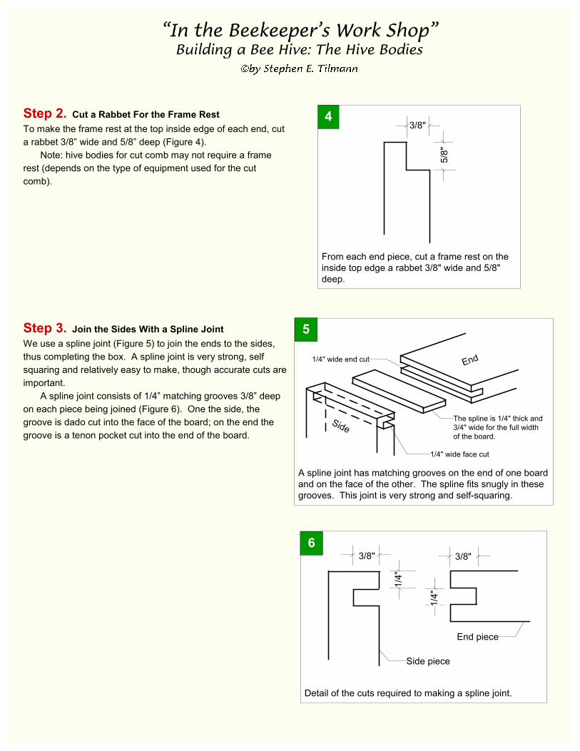
Step 2. Cut a Rabbet For the Frame Rest
To make the frame rest at the top inside edge of each end, cut
a rabbet 3/8” wide and 5/8” deep (Figure 4).
Note: hive bodies for cut comb may not require a frame
rest (depends on the type of equipment used for the cut
comb).
Step 3. Join the Sides With a Spline Joint
We use a spline joint (Figure 5) to join the ends to the sides,
thus completing the box. A spline joint is very strong, self
squaring and relatively easy to make, though accurate cuts are
important.
A spline joint consists of 1/4” matching grooves 3/8” deep
on each piece being joined (Figure 6). One the side, the
groove is dado cut into the face of the board; on the end the
groove is a tenon pocket cut into the end of the board.
Detail of the cuts required to making a spline joint.
1/4
"
3/8"
1/4
"
3/8"
Side piece
End piece
6
From each end piece, cut a frame rest on the
inside top edge a rabbet 3/8" wide and 5/8"
deep.
43/8"
5/8
"
A spline joint has matching grooves on the end of one board
and on the face of the other. The spline fits snugly in these
grooves. This joint is very strong and self-squaring.
5
The spline is 1/4" thick and
3/4" wide for the full width
of the board.
1/4" wide end cut
1/4" wide face cut
Side
End
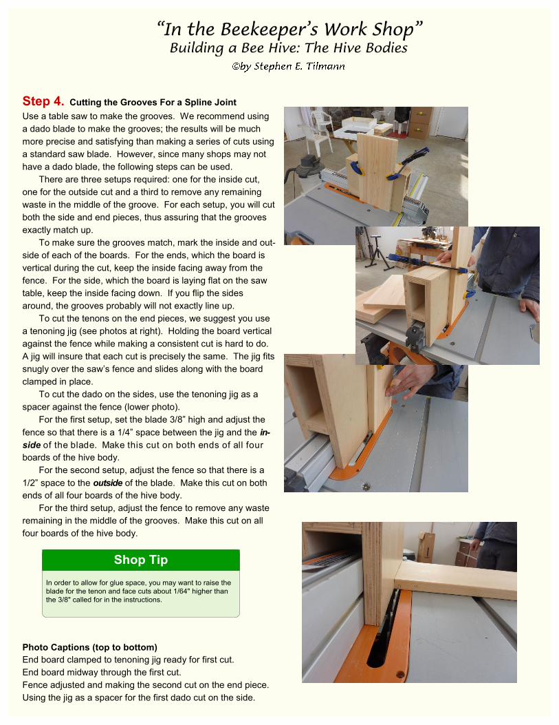
Step 4. Cutting the Grooves For a Spline Joint
Use a table saw to make the grooves. We recommend using
a dado blade to make the grooves; the results will be much
more precise and satisfying than making a series of cuts using
a standard saw blade. However, since many shops may not
have a dado blade, the following steps can be used.
There are three setups required: one for the inside cut,
one for the outside cut and a third to remove any remaining
waste in the middle of the groove. For each setup, you will cut
both the side and end pieces, thus assuring that the grooves
exactly match up.
To make sure the grooves match, mark the inside and out-
side of each of the boards. For the ends, which the board is
vertical during the cut, keep the inside facing away from the
fence. For the side, which the board is laying flat on the saw
table, keep the inside facing down. If you flip the sides
around, the grooves probably will not exactly line up.
To cut the tenons on the end pieces, we suggest you use
a tenoning jig (see photos at right). Holding the board vertical
against the fence while making a consistent cut is hard to do.
A jig will insure that each cut is precisely the same. The jig fits
snugly over the saw’s fence and slides along with the board
clamped in place.
To cut the dado on the sides, use the tenoning jig as a
spacer against the fence (lower photo).
For the first setup, set the blade 3/8” high and adjust the
fence so that there is a 1/4” space between the jig and the in-
side of the blade. Make this cut on both ends of all four
boards of the hive body.
For the second setup, adjust the fence so that there is a
1/2” space to the outside of the blade. Make this cut on both
ends of all four boards of the hive body.
For the third setup, adjust the fence to remove any waste
remaining in the middle of the grooves. Make this cut on all
four boards of the hive body.
Photo Captions (top to bottom)
End board clamped to tenoning jig ready for first cut.
End board midway through the first cut.
Fence adjusted and making the second cut on the end piece.
Using the jig as a spacer for the first dado cut on the side.
In order to allow for glue space, you may want to raise the
blade for the tenon and face cuts about 1/64" higher than
the 3/8" called for in the instructions.
Shop Tip
Step 5. Making the Splines
From 1x4 pine cut the splines which are 1/4” thick and 3/4”
wide and the length of the boards being joined (Figure 5).
When making the splines, cut along the length of the board (a
rip cut) and not across the board (a cross cut).
You may need to cut a test spline or two making minute
adjustments to the saw’s fence each time. You want the
spline to fit snugly into the grooves without having to be forced
(which might split the joint). Also, dry fit the spline in an as-
sembled joint to make sure that it is not too wide thus forcing
the boards apart. If necessary, you can sand the splines with
a coarse sandpaper to get the proper fit.
Step 6. Making the Scalloped Hand Holds
We now turn our attention to making the cutouts for the hand
holds on the outside of all four boards. The technique we de-
scribe is best made with a 10-inch radial arm saw with the
head rotated 90 degrees (like when you rip a board), though it
could be adapted for a table saw.
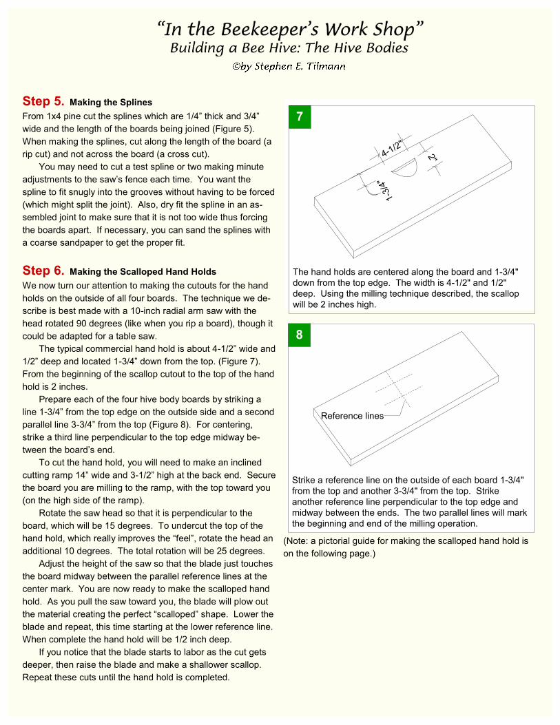
The typical commercial hand hold is about 4-1/2” wide and
1/2” deep and located 1-3/4” down from the top. (Figure 7).
From the beginning of the scallop cutout to the top of the hand
hold is 2 inches.
Prepare each of the four hive body boards by striking a
line 1-3/4” from the top edge on the outside side and a second
parallel line 3-3/4” from the top (Figure 8). For centering,
strike a third line perpendicular to the top edge midway be-
tween the board’s end.
To cut the hand hold, you will need to make an inclined
cutting ramp 14” wide and 3-1/2” high at the back end. Secure
the board you are milling to the ramp, with the top toward you
(on the high side of the ramp).
Rotate the saw head so that it is perpendicular to the
board, which will be 15 degrees. To undercut the top of the
hand hold, which really improves the “feel”, rotate the head an
additional 10 degrees. The total rotation will be 25 degrees.
Adjust the height of the saw so that the blade just touches
the board midway between the parallel reference lines at the
center mark. You are now ready to make the scalloped hand
hold. As you pull the saw toward you, the blade will plow out
the material creating the perfect “scalloped” shape. Lower the
blade and repeat, this time starting at the lower reference line.
When complete the hand hold will be 1/2 inch deep.
If you notice that the blade starts to labor as the cut gets
deeper, then raise the blade and make a shallower scallop.
Repeat these cuts until the hand hold is completed.
(Note: a pictorial guide for making the scalloped hand hold is
on the following page.)
Strike a reference line on the outside of each board 1-3/4"
from the top and another 3-3/4" from the top. Strike
another reference line perpendicular to the top edge and
midway between the ends. The two parallel lines will mark
the beginning and end of the milling operation.
8
Reference lines
The hand holds are centered along the board and 1-3/4"
down from the top edge. The width is 4-1/2" and 1/2"
deep. Using the milling technique described, the scallop
will be 2 inches high.
7
4-1/2"
2"
1-3
/4"
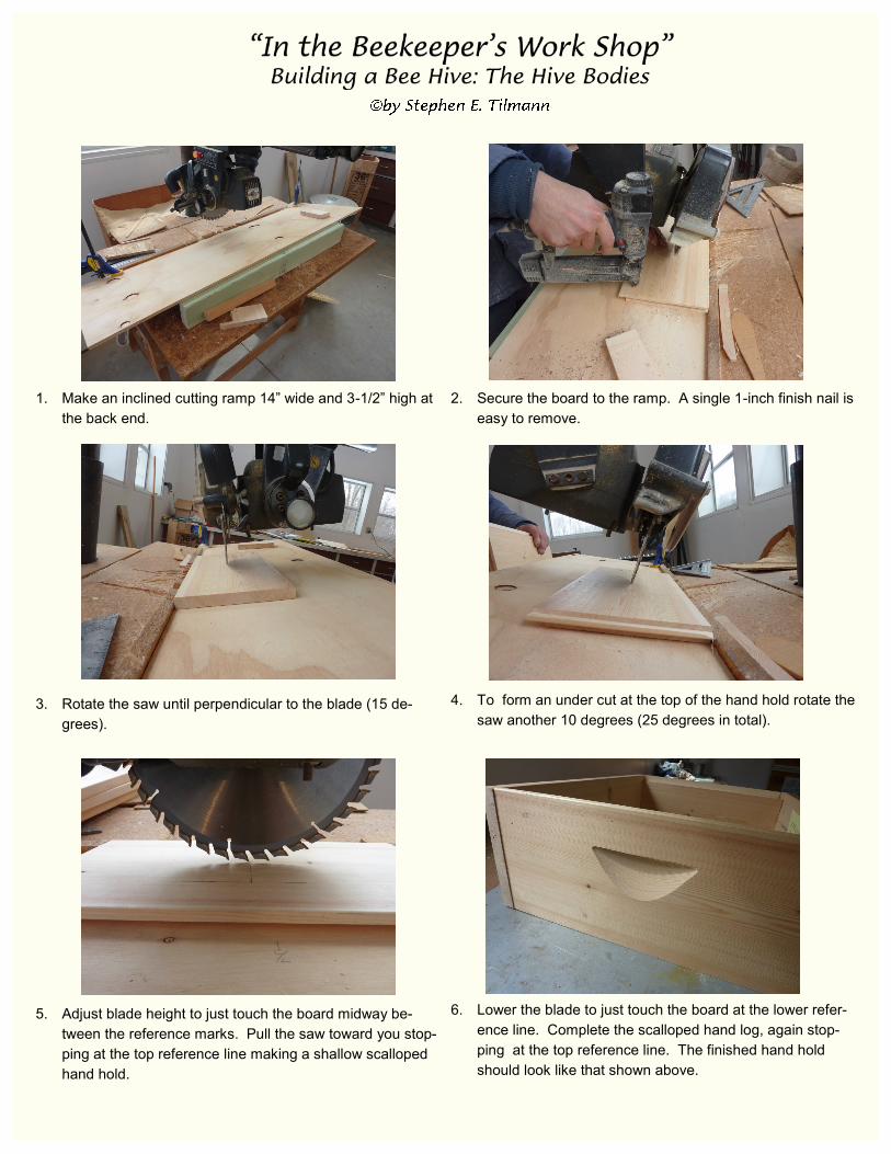
1. Make an inclined cutting ramp 14” wide and 3-1/2” high at
the back end.
3. Rotate the saw until perpendicular to the blade (15 de-
grees).
5. Adjust blade height to just touch the board midway be-
tween the reference marks. Pull the saw toward you stop-
ping at the top reference line making a shallow scalloped
hand hold.
2. Secure the board to the ramp. A single 1-inch finish nail is
easy to remove.
4. To form an under cut at the top of the hand hold rotate the
saw another 10 degrees (25 degrees in total).
6. Lower the blade to just touch the board at the lower refer-
ence line. Complete the scalloped hand log, again stop-
ping at the top reference line. The finished hand hold
should look like that shown above.
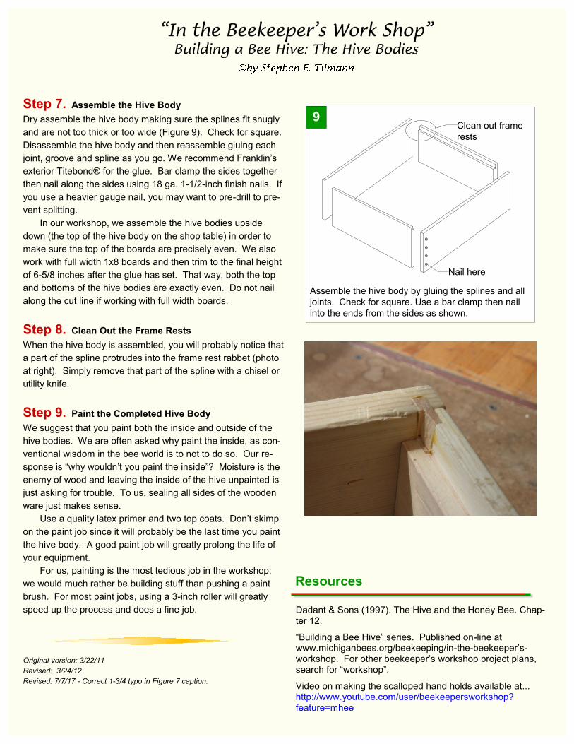
Step 7. Assemble the Hive Body
Dry assemble the hive body making sure the splines fit snugly
and are not too thick or too wide (Figure 9). Check for square.
Disassemble the hive body and then reassemble gluing each
joint, groove and spline as you go. We recommend Franklin’s
exterior Titebond® for the glue. Bar clamp the sides together
then nail along the sides using 18 ga. 1-1/2-inch finish nails. If
you use a heavier gauge nail, you may want to pre-drill to pre-
vent splitting.
In our workshop, we assemble the hive bodies upside
down (the top of the hive body on the shop table) in order to
make sure the top of the boards are precisely even. We also
work with full width 1x8 boards and then trim to the final height
of 6-5/8 inches after the glue has set. That way, both the top
and bottoms of the hive bodies are exactly even. Do not nail
along the cut line if working with full width boards.
Step 8. Clean Out the Frame Rests
When the hive body is assembled, you will probably notice that
a part of the spline protrudes into the frame rest rabbet (photo
at right). Simply remove that part of the spline with a chisel or
utility knife.
Step 9. Paint the Completed Hive Body
We suggest that you paint both the inside and outside of the
hive bodies. We are often asked why paint the inside, as con-
ventional wisdom in the bee world is to not to do so. Our re-
sponse is “why wouldn’t you paint the inside”? Moisture is the
enemy of wood and leaving the inside of the hive unpainted is
just asking for trouble. To us, sealing all sides of the wooden
ware just makes sense.
Use a quality latex primer and two top coats. Don’t skimp
on the paint job since it will probably be the last time you paint
the hive body. A good paint job will greatly prolong the life of
your equipment.
For us, painting is the most tedious job in the workshop;
we would much rather be building stuff than pushing a paint
brush. For most paint jobs, using a 3-inch roller will greatly
speed up the process and does a fine job.
Original version: 3/22/11
Revised: 3/24/12
Revised: 7/7/17 - Correct 1-3/4 typo in Figure 7 caption.
Assemble the hive body by gluing the splines and all
joints. Check for square. Use a bar clamp then nail
into the ends from the sides as shown.
9
Nail here
Clean out frame
rests
Resources
Dadant & Sons (1997). The Hive and the Honey Bee. Chap-ter 12.
“Building a Bee Hive” series. Published on-line at www.michiganbees.org/beekeeping/in-the-beekeeper’s-workshop. For other beekeeper’s workshop project plans, search for “workshop”.
Video on making the scalloped hand holds available at... http://www.youtube.com/user/beekeepersworkshop?feature=mhee
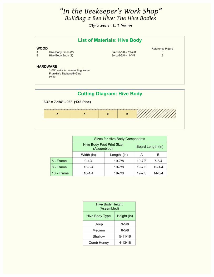
Cutting Diagram: Hive Body
3/4" x 7-1/4" - 96" (1X8 Pine)
BA A B
List of Materials: Hive Body
WOOD Reference Figure
A Hive Body Sides (2) 3/4 x 6-5/8 – 19-7/8 3
B Hive Body Ends (2) 3/4 x 6-5/8 –14-3/4 3
HARDWARE
1-3/4” nails for assembling frame
Franklin’s Titebond® Glue
Paint
5 - Frame
8 - Frame
10 - Frame
Width (in)
9-1/4
13-3/4
16-1/4
Length (in)
19-7/8
19-7/8
19-7/8
Hive Body Foot Print Size
(Assembled)
Sizes for Hive Body Components
A
19-7/8
19-7/8
19-7/8
B
7-3/4
12-1/4
14-3/4
Board Length (in)
Deep
Medium
Shallow
Comb Honey
Hive Body Type
Hive Body Height
(Assembled)
9-5/8
6-5/8
5-11/16
4-13/16
Height (in)
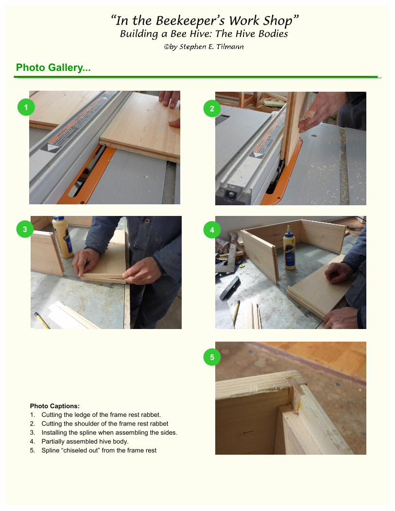
Photo Gallery...
Photo Captions:
1. Cutting the ledge of the frame rest rabbet.
2. Cutting the shoulder of the frame rest rabbet
3. Installing the spline when assembling the sides.
4. Partially assembled hive body.
5. Spline “chiseled out” from the frame rest
1
4
2
5
3


![[Japanese Content] Lance Riedel_The App Server, The Hive in Tokyo_Aug29](https://static.fdocument.pub/doc/165x107/54c6a2c44a7959df148b456d/japanese-content-lance-riedelthe-app-server-the-hive-in-tokyoaug29.jpg)