HiperPFSTM -2(PFS7326H) 및 · 별도의 바이어스 컨버터가 없기 때문에, 서플라이...
83
Power Integrations 5245 Hellyer Avenue, San Jose, CA 95138 USA. Tel: +1 408 414 9200 Fax: +1 408 414 9201 www.powerint.com 제목 HiperPFS TM -2(PFS7326H) 및 HiperLCS TM (LCS702HG)를 사용한 150W 역률 보정 LLC 파워 서플라이에 대한 레퍼런스 디자인 보고서 사양 90VAC~265VAC 입력, 150W(0~3.5A 에서 최대 43V) 출력(정전류) 애플리케이션 LED 가로등 작성자 애플리케이션 엔지니어링 부서 문서 번호 RDR-382 날짜 2014 년 5 월 28 일 개정 6.2 요약 및 기능 아주 적은 수의 부품으로 설계 가능한 고집적 PFC 및 LLC 단 저비용 페라이트 코어를 사용한 연속 모드 PFC 트랜스포머 크기를 대폭 줄이기 위한 고주파수(250kHz) LLC 115VAC 에서 풀부하 PFC 효율 95% 초과 풀부하 LLC 효율 95% 초과 115VAC/230VAC 에서 시스템 효율 각각 91%/93% 스타트 업 회로에 별도의 바이어스 서플라이가 필요 없음 온보드 전류 레귤레이션 및 아날로그 디밍 특허 정보 여기에 설명한 제품 및 애플리케이션(제품의 외장 트랜스포머 구성 및 회로 포함)은 하나 이상의 미국 및 해외 특허의 대상이 되거나 파워 인테그레이션스(Power Integrations)에서 출원 중인 미국 및 해외 특허 신청의 대상이 될 수 있습니다. 파워 인테그레이션스(Power Integrations)의 전체 특허 목록은 www.powerint.com에서 확인할 수 있습니다. 파워 인테그레이션스(Power Integrations)는 고객에게 http://www.powerint.com/ip.htm에 명시된 특정 특허권에 따라 라이센스를 부여합니다.
Transcript of HiperPFSTM -2(PFS7326H) 및 · 별도의 바이어스 컨버터가 없기 때문에, 서플라이...

Power Integrations
5245 Hellyer Avenue, San Jose, CA 95138 USA. Tel: +1 408 414 9200 Fax: +1 408 414 9201
www.powerint.com
제목
HiperPFSTM
-2(PFS7326H) 및
HiperLCSTM
(LCS702HG)를 사용한 150W 역률
보정 LLC 파워 서플라이에 대한 레퍼런스 디자인
보고서
사양 90VAC~265VAC 입력,
150W(0~3.5A에서 최대 43V) 출력(정전류)
애플리케이션 LED 가로등
작성자 애플리케이션 엔지니어링 부서
문서 번호 RDR-382
날짜 2014년 5월 28일
개정 6.2
요약 및 기능
아주 적은 수의 부품으로 설계 가능한 고집적 PFC 및 LLC단
저비용 페라이트 코어를 사용한 연속 모드 PFC
트랜스포머 크기를 대폭 줄이기 위한 고주파수(250kHz) LLC
115VAC에서 풀부하 PFC 효율 95% 초과
풀부하 LLC 효율 95% 초과
115VAC/230VAC에서 시스템 효율 각각 91%/93%
스타트 업 회로에 별도의 바이어스 서플라이가 필요 없음
온보드 전류 레귤레이션 및 아날로그 디밍
특허 정보
여기에 설명한 제품 및 애플리케이션(제품의 외장 트랜스포머 구성 및 회로 포함)은 하나 이상의 미국 및 해외 특허의 대상이
되거나 파워 인테그레이션스(Power Integrations)에서 출원 중인 미국 및 해외 특허 신청의 대상이 될 수 있습니다. 파워
인테그레이션스(Power Integrations)의 전체 특허 목록은 www.powerint.com에서 확인할 수 있습니다. 파워
인테그레이션스(Power Integrations)는 고객에게 http://www.powerint.com/ip.htm에 명시된 특정 특허권에 따라 라이센스를
부여합니다.

RDR-382, 150 W Street Light Power Supply 28-May-14
Page 2 of 83
Power Integrations, Inc. Tel: +1 408 414 9200 Fax: +1 408 414 9201 www.powerint.com
목차 1 소개 ............................................................................................................................ 6
2 파워 서플라이 사양 ..................................................................................................... 8
3 회로도 ......................................................................................................................... 9
4 회로 설명 .................................................................................................................. 11
입력 필터/부스트 컨버터/바이어스 서플라이 ..................................................... 11 4.1
EMI 필터링/돌입 제한 ........................................................................................ 11 4.2
메인 PFC단 ....................................................................................................... 11 4.3
1차측 바이어스 서플라이/스타트업 .................................................................. 11 4.4
LLC 컨버터 ........................................................................................................ 12 4.5
1차측 ................................................................................................................ 12 4.6
출력 정류 ........................................................................................................... 14 4.7
출력 전류 및 전압 제어 ...................................................................................... 14 4.8
5 PCB 레이아웃 ........................................................................................................... 16
6 BOM ......................................................................................................................... 18
7 LED 패널 특성 .......................................................................................................... 21
LED 패널 전류 공유 ........................................................................................... 22 7.1
정전압 부하 ....................................................................................................... 23 7.2
8 트랜스포머................................................................................................................ 27
PFC 초크(L2) 사양 ............................................................................................ 27 8.1
전기적 구성도 ............................................................................................. 27 8.1.1
전기적 사양 ................................................................................................ 27 8.1.2
재료 ............................................................................................................ 27 8.1.3
제작 구성도 ................................................................................................ 28 8.1.4
권선 지침 .................................................................................................... 28 8.1.5
권선 그림 .................................................................................................... 29 8.1.6
LLC 트랜스포머(T1) 사양 .................................................................................. 32 8.2
전기적 구성도 ............................................................................................. 32 8.2.1
전기적 사양 ................................................................................................ 32 8.2.2
재료 ............................................................................................................ 32 8.2.3
제작 구성도 ................................................................................................ 33 8.2.4
권선 지침 .................................................................................................... 33 8.2.5
권선 그림 .................................................................................................... 34 8.2.6
출력 인덕터(L3) 사양 ......................................................................................... 38 8.3
전기적 구성도 ............................................................................................. 38 8.3.1
전기적 사양 ................................................................................................ 38 8.3.2
재료 목록 .................................................................................................... 38 8.3.3
상세 구성 .................................................................................................... 38 8.3.4
9 PFC 설계 스프레드시트 ............................................................................................ 39
28-May-14 RDR-382, 150 W Street Light Power Supply
Page 3 of 83
Power Integrations Tel: +1 408 414 9200 Fax: +1 408 414 9201
www.powerint.com
10 LLC 트랜스포머 설계 스프레드시트 .......................................................................... 43
11 히트싱크 ................................................................................................................ 48
1차측 히트싱크 ................................................................................................. 48 11.1
1차측 히트싱크 판금 .................................................................................. 48 11.1.1
1차측 히트싱크 고정 .................................................................................. 49 11.1.2
1차측 히트싱크 어셈블리 ........................................................................... 50 11.1.3
2차측 히트싱크 ................................................................................................. 51 11.2
2차측 히트싱크 판금 .................................................................................. 51 11.2.1
2차측 히트싱크 고정 .................................................................................. 52 11.2.2
2차측 히트싱크 어셈블리 ........................................................................... 53 11.2.3
12 RD-382 성능 데이터.................................................................................................. 54
LLC단 효율 ....................................................................................................... 54 12.1
총 효율 ........................................................................................................... 55 12.2
역률 ................................................................................................................ 56 12.3
고조파 분포 .................................................................................................... 57 12.4
THD, 100% 부하 ................................................................................................ 57 12.5
출력 전류 및 디밍 입력 전압 ........................................................................... 58 12.6
13 파형 ....................................................................................................................... 59
입력 전류, 100% 부하 .................................................................................... 59 13.1
LLC 1차측 전압 및 전류 .................................................................................... 60 13.2
출력 정류기 피크 역방향 전압 ........................................................................ 61 13.3
PFC 인덕터 + 스위치 전압 및 전류, 100% 부하 ................................................. 62 13.4
스타트업 시 AC 입력 전류 및 PFC 출력 전압 ................................................. 63 13.5
LED 출력 부하 상태에서 LLC 스타트업 출력 전압 및 트랜스포머 1차측 전류 .. 63 13.6
LED 부하 상태에서 출력 전압/전류 스타트업 .................................................... 64 13.7
LLC 출력 회로 단락 ............................................................................................ 65 13.8
출력 리플 측정................................................................................................ 66 13.9
리플 측정 기술 ............................................................................................ 66 13.9.1
리플 측정 .................................................................................................... 67 13.9.2
14 온도 프로파일 ........................................................................................................ 68
90VAC, 60Hz, 150W 출력, 실온 ........................................................................ 68 14.1
115VAC, 60Hz, 150W 출력, 실온 ...................................................................... 71 14.2
230VAC, 50Hz, 150W 출력, 실온 ...................................................................... 74 14.3
15 출력 게인-위상 ...................................................................................................... 77
16 전도성 EMI ............................................................................................................ 78
17 라인 서지 테스트 ................................................................................................... 80
라인 서지 테스트 설정 .................................................................................... 80 17.1
디퍼렌셜 모드 서지, 1.2/50sec ..................................................................... 81 17.2
커먼 모드 서지, 1.2/50sec ............................................................................ 81 17.3

RDR-382, 150 W Street Light Power Supply 28-May-14
Page 4 of 83
Power Integrations, Inc. Tel: +1 408 414 9200 Fax: +1 408 414 9201 www.powerint.com
18 개정 내역............................................................................................................... 82

28-May-14 RDR-382, 150 W Street Light Power Supply
Page 5 of 83
Power Integrations Tel: +1 408 414 9200 Fax: +1 408 414 9201
www.powerint.com
중요 사항:
이 기판은 안전 절연거리 요구 사항에 맞도록 디자인되었지만 엔지니어링 프로토타입은
아직 기관 승인을 받지 않은 상태입니다. AC 입력을 프로토타입 보드에 제공하도록 절연
트랜스포머를 사용하여 모든 테스트를 수행해야 합니다.
본 디자인에서는 별도의 바이어스 컨버터가 없기 때문에, 서플라이 파워 다운 직후 벌크
커패시터 C14 에 최대 280VDC 의 값이 나타납니다. 안전을 위해서는 적절한
저항(10k/2W가 적절)을 통해 이 커패시터를 방전하거나, 취급 전에 서플라이를 최대 10분
정도 방치합니다.

RDR-382, 150 W Street Light Power Supply 28-May-14
Page 6 of 83
Power Integrations, Inc. Tel: +1 408 414 9200 Fax: +1 408 414 9201 www.powerint.com
1 소개
본 엔지니어링 보고서는 90~265VAC 범위의 LED 가로등 및 기타 고전력 조명
애플리케이션용 파워 서플라이에 대한 43V(정격), 150W 의 레퍼런스 디자인에 대해
설명합니다. 해당 파워 서플라이는 43V 에서 150W LED 패널을 직접 구동하기 위해
정전류 출력으로 설계되었습니다.
본 디자인은 PFC 프런트 엔드용 PFS7326H 와 LLC 출력단용 LCS702HG 로 구성되어
있습니다.
Figure 1 – RD-382 Photograph, Top View.

28-May-14 RDR-382, 150 W Street Light Power Supply
Page 7 of 83
Power Integrations Tel: +1 408 414 9200 Fax: +1 408 414 9201
www.powerint.com
Figure 2 – RD-382 Photograph, Bottom View.

RDR-382, 150 W Street Light Power Supply 28-May-14
Page 8 of 83
Power Integrations, Inc. Tel: +1 408 414 9200 Fax: +1 408 414 9201 www.powerint.com
2 파워 서플라이 사양
아래 표에는 설계의 최소 허용 성능이 나와 있습니다. 실제 성능은 결과 섹션에 나열되어
있습니다.
설명 기호 최소 기준값 최대 단위 설명
입력
전압 VIN 90 265 VAC 3선 입력
주파수 fLINE 47 50/60 64 Hz
역률 PF 0.97 풀부하, 230VAC
메인 컨버터 출력
출력 전압 VLG 43 V 43VDC(일반적 - LED 부하에 의해
정의됨)
출력 리플 VRIPPLE(LG) 300 mV P-P 20MHz 대역폭
출력 전류 ILG 0.00 3.5 A 무부하 상태에서 정전류 서플라이
보호
총 출력 전력
연속 출력 전력 POUT 150 W
피크 출력 전력 POUT(PK) N/A W
효율
풀부하 시 총 시스템 Main
91 93
% 115VAC, 풀부하에서 측정
230VAC, 풀부하에서 측정
환경
전도성 EMI CISPR22B/EN55022B 충족
안정성 IEC950/UL1950 클래스 II를 충족하도록 설계됨
서지
디퍼렌셜
커먼 모드
2 4
kV kV
1.2/50 s 서지, IEC 1000-4-5,
디퍼렌셜 모드: 2 커먼 모드: 12
주변 온도 TAMB 0 60 oC 자세한 상태는 써멀 섹션 참조

28-May-14 RDR-382, 150 W Street Light Power Supply
Page 9 of 83
Power Integrations Tel: +1 408 414 9200 Fax: +1 408 414 9201
www.powerint.com
3 회로도
Figure 3 – Schematic RD-382 Street Light Power Supply Application Circuit - Input Filter, PFC Power Stage, and Bias Supplies.

RDR-382, 150 W Street Light Power Supply 28-May-14
Page 10 of 83
Power Integrations, Inc. Tel: +1 408 414 9200 Fax: +1 408 414 9201 www.powerint.com
Figure 4 – Schematic of RD-382 Street light Power Supply Application Circuit, LLC Stage.

28-May-14 RDR-382, 150 W Street Light Power Supply
Page 11 of 83
Power Integrations Tel: +1 408 414 9200 Fax: +1 408 414 9201
www.powerint.com
4 회로 설명
입력 필터/부스트 컨버터/바이어스 서플라이 4.1
그림 3의 회로도는 입력 EMI 필터, PFC단 및 1차측 바이어스 서플라이/스타트업 회로를
나타냅니다. 역률 보정을 위해 PFS7326H가 사용되었습니다. 1차측 및 2차측 바이어스
서플라이는 PFC 인덕터(L2)의 권선으로부터 생성합니다.
EMI 필터링/돌입 제한 4.2
커패시터 C1 및 C2는 디퍼렌셜 모드의 노이즈를 제어하기 위해 사용됩니다. 저항 R1은
댐핑, 역률 개선 및 EMI 감소를 위해 사용됩니다. 저항 R2~R4는 AC 전원이 제거되었을
때 C1 및 C2를 방전합니다. 인덕터 L1은 커먼 모드 EMI를 제어합니다. U1, U3 및 BR1의
히트싱크는 1 차측 복귀에 연결되어 히트싱크가 방사 노이즈/용량성 커플링 노이즈의
소스가 되지 않도록 합니다. 써미스터 RT1 은 돌입 제한 기능을 제공합니다. 커패시터
C33(그림 4)은 커먼 모드 EMI 를 필터링합니다. 인덕터 L4 는 디퍼렌셜 모드 EMI 를
필터링합니다.
메인 PFC단 4.3
R17~R19 및 R23은 출력 전압 피드백을 제공합니다. 커패시터 C15는 PFC 회로의 빠른
언더슈트 및 오버슈트 응답을 위해 U1 FB 핀에 빠른 dv/dt 피드백을 제공합니다. C19, C20,
R21, R22 및 R24에서는 주파수가 보상됩니다. 저항 R10~R12(C10에 의해 필터링됨)는
입력 전압 정보를 U1에 제공합니다. 저항 R13(C11에 의해 필터링됨)은 U1을 “효율성”
모드로 프로그래밍합니다. HiperPFS-2 효율성 모드에 대한 더 자세한 내용은 HiperPFS-2
데이터 시트를 참조하십시오. 저항 R14 는 U1 에 대한 “power good” 기준값을
프로그래밍합니다.
커패시터 C12는 U1에 로컬 바이패싱을 제공합니다. 다이오드 D2는 AC가 처음 인가될
때 PFC 출력 커패시터(C14)를 충전해 PFC 인덕터 L2 및 U1 의 내부 출력 다이오드에
돌입 전류가 흐르지 않도록 합니다. 커패시터 C13 및 저항 R15~R16은 U1및 C14 부품
주변의 고주파수 루프의 길이를 단축하여 EMI를 줄이는 데 사용됩니다. 이러한 저항은
C13과 직렬로 연결되어 중간 대역 EMI 피크를 댐핑합니다. 들어오는 AC 전류는 BR1에
의해 정류되고 C9로 필터링됩니다. 커패시터 C9는 U1 ON 타임일 때 L2를 통해 높은
순간 전류를 보내기 위해 저손실의 폴리프로필렌 유형이 선택되었습니다. 써미스터
RT1은 스타트업 시 돌입 전류를 제한합니다.
1차측 바이어스 서플라이/스타트업 4.4
R5~R7, R8~R9, Q1 및 VR3 부품은 U1 에 스타트업 바이어스를 제공합니다. U1 이
작동하기 시작하면 D1, D3 및 C3~C5 부품은 PFC 초크 L2 의 권선을 통해 1 차측에
필요한 바이어스 서플라이를 발생시킵니다. 이는 파워 서플라이의 PFC 및 LLC단 모두를
구동하는 데 사용됩니다. 1 차측 바이어스 서플라이 전압이 형성되면, 다이오드 D6 을

RDR-382, 150 W Street Light Power Supply 28-May-14
Page 12 of 83
Power Integrations, Inc. Tel: +1 408 414 9200 Fax: +1 408 414 9201 www.powerint.com
통해 MOSFET Q1 을 턴오프시켜 전력 소비량을 줄입니다. 저항 R8 및 R9 는 파워
서플라이가 작동을 시작하지 않을 경우 Q1이 과도하게 전력을 소모하지 않도록 합니다.
D7, Q2, C16~C17 및 VR2는 U1 및 U3의 바이어스 서플라이 전압을 레귤레이션합니다.
D4, D5 및 C6~C8 은 2 차측 제어 회로용으로 L2 의 3 중 절연 권선을 통해 바이어스
서플라이를 발생시킵니다.
LLC 컨버터 4.5
그림 4의 회로도는 LCS702HG를 사용하여 구현된 최대 43V, 150W LLC DC-DC 정전류
출력 컨버터입니다.
1차측 4.6
집적 회로 U3은 LLC 공진형 하프 브리지(HB) 컨버터에 필요한 제어 회로, 드라이버 및
출력 MOSFET를 포함하고 있습니다. U3의 HB 출력은 블로킹/공진형 커패시터(C30)를
통해 출력 트랜스포머 T1을 구동합니다. 이 커패시터는 동작 리플 전류를 만족하며 고장
상태에서 인가되는 고전압을 견딜 수 있습니다.
트랜스포머 T1 은 49H 의 누설 인덕턴스용으로 설계되었으며, 다음 식에 따라 공진형
커패시터 C30과 함께 1차측 직렬 공진 주파수(대략 259kHz)를 설정합니다.
RL
RCL
f
28.6
1
여기서 fR은 직렬 공진 주파수(Hertz)이고, LL은 트랜스포머 누설 인덕턴스(Henry)이며,
CR은 공진형 커패시터(C30) 값(Farad)입니다.
1 차측 턴 수를 조정하여 트랜스포머 권선비를 설정했으므로 정격 입력 전압 및
풀부하에서 동작 주파수는 앞서 설명한 공진 주파수에 근접하거나 그보다 약간 작습니다.
트랜스포머 크기, 출력 필터 커패시턴스(세라믹/필름 커패시터 사용) 및 효율을 고려할 때
동작 주파수로 250kHz가 적절합니다.
코어 및 구리 손실을 고려하여 2차측 권선 턴 수를 선택했습니다. 1차측에는 AWG #44
리츠선을, 2 차측에는 AWG #42 리츠선을 사용했으며 이러한 조합으로 동작 주파수(약
250kHz)에서 높은 효율을 제공합니다. 보빈의 활용도(사용 가능한 공간) 및 구리 손실
간의 균형을 맞추기 위해 리츠선의 각 게이지 내 가닥 수를 선택했습니다.
선택한 코어 재료는 PW4(Itacoil)입니다. 이 재료는 양호한 성능(낮은 손실)을
제공했습니다.

28-May-14 RDR-382, 150 W Street Light Power Supply
Page 13 of 83
Power Integrations Tel: +1 408 414 9200 Fax: +1 408 414 9201
www.powerint.com
U3의 내부 하이 사이드 드라이버에 전력을 공급하는 부트스트랩 회로는 부품 D9, R35 및
C28로 구성됩니다.
R34 및 C25 는 U1 를 위한 VCC 서플라이인 +12V 입력을 필터링하고 바이패스합니다.
참고: VCC 전압이 15V를 초과하는 경우 U3이 손상될 수 있습니다.
전압 분배기 저항 R26~R29는 U3의 고전압 턴온, 턴오프 및 과전압 기준값을 설정합니다.
전압 분배기 값은 360VDC 에서 LLC 턴온 지점이, 285VDC 에서 턴오프 지점이,
473VDC 에서 입력 과전압 턴오프 지점이 설정되도록 선택되었습니다. 내장된
히스테리시스는 280VDC에서 저전압 턴오프 지점을 설정합니다.
커패시터 C29는 U3의 D 및 S1/S2 핀 사이에 짧은 패턴으로 연결된 +380V 입력용 고주파
바이패스 커패시터입니다. 직렬 저항 R41~R42는 EMI를 댐핑합니다.
커패시터 C31은 C30과 함께 전류 분배기를 형성하며 1차측 전류의 일부를 샘플링하는
데 사용됩니다. 저항 R40 이 이 전류를 감지하고 결과 신호는 R39 및 C27 에 의해
필터링됩니다. 커패시터 C31 은 고장 상태 동안 인가되는 피크 전압에 맞춰 정격을
지정해야 하며 금속 필름, SL 세라믹 또는 NPO/COG 세라믹과 같은 안정적이고 저손실의
유전체를 사용해야 합니다. RD-382 에 사용되는 커패시터는 "SL" 온도 특성을 갖는
세라믹 디스크로, 일반적으로 CCFL 튜브용 드라이버에 사용됩니다. 선택한 값은 다음
식에 따라 4.25A에서 1사이클(빠름) 전류 제한과 2.35A에서 7사이클(느림) 전류 제한을
설정합니다.
403130
31
5.0
RCC
CICL
ICL은 7사이클 전류 제한(암페어)이고, R40은 전류 제한 저항(Ohm)이며, C30 및 C31은
각각 공진형 및 전류 샘플링 커패시터(나노패럿)입니다. 1 사이클 전류 제한의 경우 위
식에서 0.5V를 0.9V로 바꿉니다.
저항 R39 및 커패시터 C27은 1차측 전류 신호를 IS 핀으로 필터링합니다. 저항 R39는
최소 권장 값인 220으로 설정됩니다. C27 값은 노이즈로 인한 불필요한 동작을
방지하기 위해 1nF로 설정되며, 이 값은 위의 계산에서 알 수 있듯이 전류 제한 설정 값에
실질적인 영향을 줄 만큼 높은 값이 아닙니다. 이러한 부품은 효율성을 최대화하기 위해 IS
핀 가까이 배치해야 합니다. IS 핀은 마이너스 전류를 견딜 수 있으므로 전류 센싱에
복잡한 정류 구성이 필요하지 않습니다.
R33 및 R38의 테브닌(Thevenin) 등가 조합은 데드 타임을 330ns로 설정하고 U3의 최대
동작 주파수를 847kHz로 설정합니다. U3의 DT/BF 입력은 C23에 의해 필터링됩니다.

RDR-382, 150 W Street Light Power Supply 28-May-14
Page 14 of 83
Power Integrations, Inc. Tel: +1 408 414 9200 Fax: +1 408 414 9201 www.powerint.com
R33 및 R38의 조합에서도 U3용으로 버스트 모드 "1"을 선택합니다. 그러면 하위 및 상위
버스트 기준 주파수가 각각 382kHz 및 437kHz로 설정됩니다.
FEEDBACK 핀은 FEEDBACK 핀으로의 A 당 2.6kHz 의 근사치 특성을 갖습니다.
FEEDBACK 핀에 흐르는 전류에 따라 U3 의 동작 주파수가 높아지고 출력 전압이
낮아집니다. R30 및 R31 의 직렬 조합은 U3 의 최소 동작 주파수를 대략 160kHz 로
설정합니다. 이 값은 풀부하 및 최소 벌크 커패시터 전압에서 레귤레이션에 필요한
주파수보다 약간 낮게 설정됩니다. 저항 R30은 C21에 의해 바이패스되며 피드백 루프
오픈 시, 초기에 FEEDBACK 핀으로 보다 높은 전류가 흐르도록 하여 스타트업 동안 출력
소프트 스타트를 가능하게 합니다. 그러면 스위칭 주파수는 높은 값에서 시작된 후 출력
전압이 레귤레이션에 도달할 때까지 차차 감소합니다. 저항 R31은 일반적으로 R33 및
R38의 병렬 조합과 동일한 값으로 설정되므로 소프트 스타트 시 초기 주파수는 R33 및
R38에 의해 설정된 값과 마찬가지로 최대 스위칭 주파수와 동일합니다. R31 값이 이보다
작은 경우에는 입력 전압을 인가하면 스위칭이 일어날 때까지 지연이 발생합니다.
옵토커플러 U4 는 R32 를 통해 U3 의 FEEDBACK 핀을 동작시키며, 이때 R32 는
FEEDBACK 핀으로 흐르는 최대 옵토커플러 전류를 제한하는 역할을 합니다. 커패시터
C26 은 FEEDBACK 핀을 필터링합니다. 저항 R36 은 옵토커플러의 부하로 동작하여
옵토커플러를 비교적 높은 대기 전류에서 작동시키므로 게인이 증가합니다. 저항 R32 및
R36 역시 큰 신호 단계 응답 및 버스트 모드 출력 리플을 개선합니다. 다이오드 D10은
FMAX/소프트 스타트 네트워크로부터 R36을 절연합니다.
출력 정류 4.7
트랜스포머 T1 의 출력은 D11 및 C34~C35 에 의해 정류되고 필터링됩니다. 이러한
커패시터의 재질은 출력 리플 정격 전류를 고려하여 선택한 폴리에스터 유전체입니다.
출력 정류기 D11은 고효율을 위해 선택된 150V 쇼트키 정류기입니다. 트랜스포머 2차측
권선 절반을 서로 꼬아서 사용하면(섹션 8의 트랜스포머 구조 참조) 두 2차측 절반 간의
누설 인덕턴스가 감소하고, 최악의 조건에서의 역방향 피크 전압이 감소시켜 150V 쇼트키
다이오드를 높은 효율로 사용할 수 있습니다. L3 및 C36이 추가적인 출력 필터 기능을
합니다. 커패시터 C36 또한 LLC "가상" 출력 직렬 R-L과 출력 커패시터 C34~C35에 의한
LLC 출력 임피던스 피크(약 30kHz)를 댐핑합니다.
출력 전류 및 전압 제어 4.8
출력 전류가 저항 R52 및 R53 을 통해 감지됩니다. 이러한 저항은 출력 단락 회로
상태에서 전류 제어 회로에 피해를 주지 않기 위해 다이오드 D13에 의해 클램핑됩니다.
R45 및 U2는 전류 센싱 앰프 U5에 전압 레퍼런스를 제공합니다. 해당 레퍼런스 전압은
R46~R47 및 R50 에 의해 분배되고 C39 에 의해 필터링됩니다. 전류 센싱 저항에서의
전압은 R51 및 C41에 의해 필터링되고 U5의 비반전 입력에 인가됩니다. Op-Amp U5는
D12 및 R25를 통해 옵토커플러 U4를 작동시킵니다. R25, R44, R51, C38, 및 C41는
전류 루프의 주파수를 보상합니다. VR1 및 R43 은 출력 부하가 제거된 경우 파워

28-May-14 RDR-382, 150 W Street Light Power Supply
Page 15 of 83
Power Integrations Tel: +1 408 414 9200 Fax: +1 408 414 9201
www.powerint.com
서플라이를 보호하기 위해 출력 전압을 센싱합니다. 이때, 소프트 전압 제한 특성을
제공하기 위해 R43에 비교적 큰 값을 사용하고 VR1에 비교적 낮은 전압을 사용하도록
선택되었습니다. 이렇게 하면 V-I 곡선의 무릎 지점에서 발진을 방지하고 특정 LED
부하에서 서플라이의 스타트업 특성을 개선하는 데 도움이 됩니다.
J3, Q3~Q4, R48~R49, R54~R55, R46, C40은 원격 디밍 기능을 제공하는 데 사용됩니다.
J3 에서 디밍 전압은 R54 및 R55 에 의해 전류로 변환되고 전류 미러 Q3~Q4 를 통해
R46 에 인가됩니다. 이 전류는 전류 센싱 앰프 U5 에서 레퍼런스 전압으로 풀다운되고
프로그래밍된 출력 전류를 감소시킵니다. 0~10VDC 의 디밍 전압은 0V 에서 100%,
10VDC 입력에서 최대 20%의 출력 전류 범위를 제공합니다.

RDR-382, 150 W Street Light Power Supply 28-May-14
Page 16 of 83
Power Integrations, Inc. Tel: +1 408 414 9200 Fax: +1 408 414 9201 www.powerint.com
5 PCB 레이아웃
Figure 5 – Printed Circuit Layout, Top Side.
28-May-14 RDR-382, 150 W Street Light Power Supply
Page 17 of 83
Power Integrations Tel: +1 408 414 9200 Fax: +1 408 414 9201
www.powerint.com
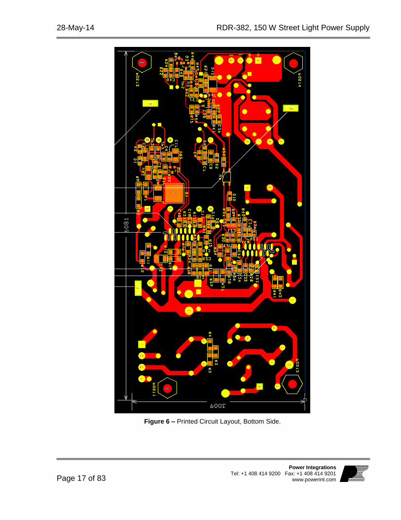
Figure 6 – Printed Circuit Layout, Bottom Side.

RDR-382, 150 W Street Light Power Supply 28-May-14
Page 18 of 83
Power Integrations, Inc. Tel: +1 408 414 9200 Fax: +1 408 414 9201 www.powerint.com
6 BOM Item Qty Ref Des Description Mfg Part Number Mfg
1 1 BR1 600 V, 8 A, Bridge Rectifier, GBU Case GBU8J-BP Micro Commercial
2 1 C1 470 nF, 275 VAC, Film, X2 PX474K31D5 Carli
3 1 C2 220 nF, 275 VAC, Film, X2 ECQ-U2A224ML Panasonic
4 7 C3 C4 C6 C7 C37 C39 C40
100 nF, 50 V, Ceramic, X7R, 0805 CC0805KRX7R9BB104 Yageo
5 2 C5 C8 1 F, 100 V, Ceramic, X7R, 1206 HMK316B7105KL-T Taiyo Yuden
6 1 C9 470 nF, 450 V, METALPOLYPRO ECW-F2W474JAQ Panasonic
7 1 C10 22 nF, 50 V, Ceramic, X7R, 0805 ECJ-2VB1H223K Panasonic
8 1 C11 1 nF, 200 V, Ceramic, X7R, 0805 08052C102KAT2A AVX
9 1 C12 3.3 F, 25 V, Ceramic, X7R, 0805 C2012X7R1E335K TDK
10 1 C13 22 nF, 630 V, Ceramic, X7R, 1210 GRM32QR72J223KW01L Murata
11 1 C14 120 F, 450 V, Electrolytic, 20 %, (18 x 37mm) 450BXW120MEFC18X35 Rubycon
12 1 C15 47 nF, 200 V, Ceramic, X7R, 1206 12062C473KAT2A AVX
13 1 C16 47 F, 50 V, Electrolytic, 20 %, (6.3 x 12.5 mm) 50YXM47MEFC6.3X11 Rubycon
14 2 C17 C19 2.2 F, 25 V, Ceramic, X7R, 0805 C2012X7R1E225M TDK
15 1 C18 22 nF 50 V, Ceramic, X7R, 0603 C1608X7R1H223K TDK
16 1 C20 47 nF, 50 V, Ceramic, X7R, 0805 GRM21BR71H473KA01L Murata
17 1 C21 330 nF, 50 V, Ceramic, X7R, 0805 GRM219R71H334KA88D Murata
18 1 C22 33 nF, 50 V, Ceramic, X7R, 0805 CC0805KRX7R9BB333 Yageo
19 3 C23 C26 C41 4.7 nF, 200 V, Ceramic, X7R, 0805 08052C472KAT2A AVX
20 2 C24 C25 1 F, 25 V, Ceramic, X7R, 1206 C3216X7R1E105K TDK
21 1 C27 1 nF, 200 V, Ceramic, X7R, 0805 08052C102KAT2A AVX
22 1 C28 330 nF, 50 V, Ceramic, X7R FK24X7R1H334K TDK
23 1 C29 47 nF, 630 V, Film MEXPD24704JJ Duratech
24 1 C30 8.2 nF, 1000V VDC, Film B32671L0822J000 Epcos
25 1 C31 47 pF, 1 kV, Disc Ceramic DEA1X3A470JC1B Murata
26 1 C32 22 nF, 200 V, Ceramic, X7R, 0805 08052C223KAT2A AVX
27 1 C33 2.2 nF, Ceramic, Y1 440LD22-R Vishay
28 2 C34 C35 4.7 F, 63 V, Polyester Film B32560J475K Epcos
29 1 C36 120 F, 63 V, Electrolytic, Gen. Purpose, (8 x 22)
EEU-FR1J121LB Panasonic
30 1 C38 10 nF, 200 V, Ceramic, X7R, 0805 08052C103KAT2A AVX
31 2 CLIP_LCS_PFS1 CLIP_LCS_PFS2
Heat sink Hardware, Clip LCS_II/PFS EM-285V0 Kang Yang
Hardware Enterprise
32 8 D1 D3 D4 D5 D6
D7 D10 D12 100 V, 0.2 A, Fast Switching, 50 ns, SOD-323 BAV19WS-7-F Diodes, Inc.
33 1 D2 1000 V, 3 A, Recitifier, DO-201AD 1N5408-T Diodes, Inc.
34 1 D8 75 V, 200 mA, Rectifier, SOD323 BAS16HT1G ON Semi
35 1 D9 600 V, 1 A, Ultrafast Recovery, 75 ns, DO-41 UF4005-E3 Vishay
36 1 D11 150 V, 20 A, Schottky, TO-220AB DSSK 20-015A IXYS
37 1 D13 100 V, 1 A, Rectifier, Glass Passivated, DO-213AA (MELF)
DL4002-13-F Diodes, Inc.
38 1 F1 5 A, 250V, Slow, TR5 37215000411 Wickman
39 1 HS1 HEAT SINK, Custom, Al, 3003, 0.062" Thk Custom
40 1 HS2 HEAT SINK, Custom, Al, 3003, 0.062" Thk Custom
41 1 J1 3 Position (1 x 3) header, 0.156 pitch, Vertical B3P-VH JST
42 1 J2 4 Position (1 x 4) header, 0.156 pitch, Vertical 26-48-1045 Molex
43 1 J3 2 Position (1 x 2) header, 0.1 pitch, Vertical 22-23-2021 Molex

28-May-14 RDR-382, 150 W Street Light Power Supply
Page 19 of 83
Power Integrations Tel: +1 408 414 9200 Fax: +1 408 414 9201
www.powerint.com
44 3 JP1 JP2 JP3 0 , 5%, 1/4 W, Thick Film, 1206 ERJ-8GEY0R00V Panasonic
45 2 JP4 JP5 0 , 5%, 1/8 W, Thick Film, 0805 ERJ-6GEY0R00V Panasonic
46 1 JP6 Wire Jumper, Insulated, TFE, #18 AWG, 1.4 in C2052A-12-02 Alpha
47 1 JP7 Wire Jumper, Non insulated, #22 AWG, 0.7 in 298 Alpha
48 1 JP8 Wire Jumper, Non insulated, #22 AWG, 0.3 in 298 Alpha
49 1 JP9 Wire Jumper, Insulated, #24 AWG, 0.9 in C2003A-12-02 Gen Cable
50 1 JP10 Wire Jumper, Non insulated, #22 AWG, 0.6 in 298 Alpha
51 1 JP11 Wire Jumper, Non insulated, #22 AWG, 0.8 in 298 Alpha
52 2 JP12 JP15 Wire Jumper, Non insulated, #22 AWG, 0.5 in 298 Alpha
53 1 JP13 Wire Jumper, Insulated, #24 AWG, 0.8 in C2003A-12-02 Gen Cable
54 1 JP14 Wire Jumper, Insulated, #24 AWG, 0.5 in C2003A-12-02 Gen Cable
55 1 L1 9 mH, 5 A, Common Mode Choke T22148-902S P.I. Custom Fontaine
56 1 L2 Custom, RD-382 PFC Choke, 437 uH, PQ32/30, Vertical, 9 pins
Power Integrations
57 1 L3 Output Inductor, Custom, 300 nH, ±15%, constructed on Micrometals T30-26 toroidal core
Power Integrations
58 1 L4 150 H, 3.4 A, Vertical Toroidal 2114-V-RC Bourns
59 4 POST1 POST2 POST3 POST4
Post, Circuit Board, Female, Hex, 6-32, snap, 0.375L, Nylon
561-0375A Eagle Hardware
60 1 Q1 400 V, 2 A, 4.4 Ohm, 600 V, N-Channel, DPAK IRFRC20TRPBF Vishay
61 3 Q2 Q3 Q4 NPN, Small Signal BJT, GP SS, 40 V, 0.6 A, SOT-23
MMBT4401LT1G Diodes, Inc.
62 1 R1 4.7 , 2 W, Flame Proof, Pulse Withstanding, Wire Wound
WHS2-4R7JA25 IT Elect_Welwyn
63 3 R2 R3 R4 680 k, 5%, 1/4 W, Thick Film, 1206 ERJ-8GEYJ684V Panasonic
64 3 R5 R6 R7 1.3 M, 5%, 1/4 W, Thick Film, 1206 ERJ-8GEYJ135V Panasonic
65 2 R8 R9 7.5 k, 5%, 1 W, Metal Oxide RSF100JB-7K5 Yageo
66 3 R10 R11 R17 1.50 M, 1%, 1/4 W, Thick Film, 1206 ERJ-8ENF1504V Panasonic
67 1 R12 1 M, 1%, 1/8 W, Thick Film, 0805 ERJ-6ENF1004V Panasonic
68 1 R13 49.9 k, 1%, 1/16 W, Thick Film, 0603 ERJ-3EKF4992V Panasonic
69 1 R14 100 k, 1%, 1/4 W, Metal Film MFR-25FBF-100K Yageo
70 3 R15 R16 R34 4.7 , 5%, 1/4 W, Thick Film, 1206 ERJ-8GEYJ4R7V Panasonic
71 1 R18 787 k, 1%, 1/4 W, Thick Film, 1206 ERJ-8ENF7873V Panasonic
72 1 R19 1.60 M, 1%, 1/4 W, Thick Film, 1206 ERJ-8ENF1604V Panasonic
73 1 R20 39 k, 5%, 1/8 W, Thick Film, 0805 ERJ-6GEYJ393V Panasonic
74 1 R21 6.2 k, 5%, 1/8 W, Thick Film, 0805 ERJ-6GEYJ622V Panasonic
75 1 R22 487 k, 1%, 1/16 W, Thick Film, 0603 ERJ-3EKF4873V Panasonic
76 1 R23 60.4 k, 1%, 1/8 W, Thick Film, 0805 ERJ-6ENF6042V Panasonic
77 1 R24 3 k, 5%, 1/8 W, Thick Film, 0805 ERJ-6GEYJ302V Panasonic
78 3 R25 R32 R37 1 k, 5%, 1/8 W, Thick Film, 0805 ERJ-6GEYJ102V Panasonic
79 3 R26 R27 R28 976 k, 1%, 1/4 W, Thick Film, 1206 ERJ-8ENF9763V Panasonic
80 1 R29 19.6 k, 1%, 1/16 W, Thick Film, 0603 ERJ-3EKF1962V Panasonic
81 1 R30 46.4 k, 1%, 1/8 W, Thick Film, 0805 ERJ-6ENF4642V Panasonic
82 1 R31 5.76 k, 1%, 1/8 W, Thick Film, 0805 ERJ-6ENF5761V Panasonic
83 1 R33 6.81 k, 1%, 1/4 W, Metal Film MFR-25FBF-6K81 Yageo
84 1 R35 2.2 , 5%, 1/4 W, Carbon Film CFR-25JB-2R2 Yageo
85 3 R36 R44 R45 4.7 k, 5%, 1/8 W, Thick Film, 0805 ERJ-6GEYJ472V Panasonic
86 1 R38 127 k, 1%, 1/8 W, Thick Film, 0805 ERJ-6ENF1273V Panasonic
87 1 R39 220 , 5%, 1/10 W, Thick Film, 0603 ERJ-3GEYJ221V Panasonic
88 1 R40 36 , 5%, 1/8 W, Thick Film, 0805 ERJ-6GEYJ360V Panasonic
89 2 R41 R42 1 , 5%, 1/4 W, Thick Film, 1206 ERJ-8GEYJ1R0V Panasonic

RDR-382, 150 W Street Light Power Supply 28-May-14
Page 20 of 83
Power Integrations, Inc. Tel: +1 408 414 9200 Fax: +1 408 414 9201 www.powerint.com
90 1 R43 10 k, 5%, 1/4 W, Carbon Film CFR-25JB-10K Yageo
91 2 R46 R50 10 k, 1%, 1/8 W, Thick Film, 0805 ERJ-6ENF1002V Panasonic
92 1 R47 121 k, 1%, 1/8 W, Thick Film, 0805 ERJ-6ENF1213V Panasonic
93 2 R48 R49 100 , 5%, 1/8 W, Thick Film, 0805 ERJ-6GEYJ101V Panasonic
94 1 R51 20 k, 5%, 1/8 W, Thick Film, 0805 ERJ-6GEYJ203V Panasonic
95 2 R52 R53 0.1 , 5%, 2 W, Thick Oxide MO200J0R1B Synton-Tech
96 2 R54 R55 24.9 k, 1%, 1/8 W, Thick Film, 0805 ERJ-6ENF2492V Panasonic
97 1 RT1 NTC Thermistor, 2.5 , 5 A SL10 2R505 Ametherm
98 4 RTV1 RTV2 RTV3 RTV4
Thermally conductive Silicone Grease 120-SA Wakefield
99 1 RV1 320 V, 80 J, 14 mm, RADIAL V320LA20AP Littlefuse
100 4
SCREW1 SCREW2 SCREW3 SCREW4
SCREW MACHINE PHIL 6-32 X 5/16 SS PMSSS 632 0031 PH Building Fasteners
101 2 SPACER_CER1 SPACER_CER2
SPACER RND, Steatite C220 Ceramic CER-2 Richco
102 1 T1 Integrated Resonant Transformer, Horizontal, 8 pins
TRLEV25043A Itacoil
103 2 TP1 TP3 Test Point, RED, THRU-HOLE MOUNT 5010 Keystone
104 4 TP2 TP4 TP5
TP6 Test Point, BLK, THRU-HOLE MOUNT 5011 Keystone
105 1 U1 HiperPFS-2, ESIP16/13 PFS7326H Power Integrations
106 1 U2 IC, REG ZENER SHUNT ADJ SOT-23 LM431AIM3/NOPB National Semi
107 1 U3 HiperLCS, ESIP16/13 LCS702HG Power Integrations
108 1 U4 Optocoupler, 80 V, CTR 80-160%, 4-Mini Flat PC357N1TJ00F Sharp
109 1 U5 OP AMP SINGLE LOW PWR SOT23-5 LM321MF National Semi
110 1 VR1 39 V, 5%, 500 mW, DO-35 1N5259B-T Diodes, Inc.
111 1 VR2 12 V, 5%, 500 mW, DO-213AA (MELF) ZMM5242B-7 Diodes, Inc.
112 1 VR3 18 V, 5%, 500 mW, DO-213AA (MELF) ZMM5248B-7 Diodes, Inc.
114 4
WASHER1 WASHER2 WASHER3 WASHER4
Washer Flat #6, SS, Zinc Plate, 0.267 OD x 0.143 ID x 0.032 Thk
620-6Z Olander

28-May-14 RDR-382, 150 W Street Light Power Supply
Page 21 of 83
Power Integrations Tel: +1 408 414 9200 Fax: +1 408 414 9201
www.powerint.com
7 LED 패널 특성
A commercial 150 W LED streetlight was used to test the RD-382 power supply. The LED array consisted of (6) 7 X 4 panels, as 4 wide, 7 deep. For the purposes of testing, the six panels were connected in series-parallel, resulting in an LED array 12 wide, 14 deep (see Figures 8 and 9). The V-I characteristic of the LED panels connected in this manner is shown below in Figure 7.
Figure 7 – Streetlight LED Array V-I Characteristic.
38
39
40
41
42
43
44
45
0.0 0.5 1.0 1.5 2.0 2.5 3.0 3.5 4.0
Vo
lta
ge
Dro
p (
V)
Current (A)

RDR-382, 150 W Street Light Power Supply 28-May-14
Page 22 of 83
Power Integrations, Inc. Tel: +1 408 414 9200 Fax: +1 408 414 9201 www.powerint.com
LED 패널 전류 공유 7.1
For the purpose of this report, the six LED panels in the street light were partitioned into 3 sections, each section consisting of two LED panels in series. Each panel was internally connected as an array of LEDs 4 wide and 7 deep so that two panels connected in series consisted of an array of LEDS 4 wide by 14 deep. The three sections were connected in parallel, forming a total LED load 12 wide and 14 deep. Using a DC current probe, the current in each 4 wide by 14 deep section was measured to determine the current distribution between sections, with results shown below. 1 2 3
Figure 8 – LED Test Panel Layout. Figure 9 – Array of LEDs in Each Test Panel.
Section # 1 2 3
Current (A) 1.113 A 1.159 A 1.126 A
Maximum difference between sections was <5%.

28-May-14 RDR-382, 150 W Street Light Power Supply
Page 23 of 83
Power Integrations Tel: +1 408 414 9200 Fax: +1 408 414 9201
www.powerint.com
정전압 부하 7.2
Since this power supply has a constant current output tailored for a relatively fixed constant voltage load, the usual constant current electronic load cannot be used for testing. For bench testing at maximum power, a constant resistance load can be used, set such that the supply output is at maximum current and an output voltage of 43-44 V, as indicated by the V-I curve shown in Figure 7. Other testing, including dimming and gain-phase, will require the actual LED load or a constant voltage load that closely mimics its characteristics. The streetlight LED as a load was both large and heavy. In order to facilitate EMI and surge testing, a constant voltage load was constructed to emulate the behavior of the LED array in a much smaller package. The circuit is shown in Figure 8. The load consists of paralleled power Darlington transistors Q1-5, each with an emitter resistor (R1-5) to facilitate current sharing. Base resistors R6-10 help prevent oscillation. A string of thirteen 3 mm blue LEDs (D1-13) are used as a voltage reference to mimic the characteristics of the LED panel. Resistor R11 is adjusted to vary the voltage at which the load turns on to match the characteristics of the LED panel. Resistors R12-14 add extra impedance in series with the load to approximate the characteristics of the LED panel. The completed array with heat sink is shown in Figure 9. A small fan was used to cool the heat sink when the load was operated for extended periods at full power. The V-I characteristics of the CV load are shown superimposed on those of the LED array in Figure 10. An electronic load with appropriate rating and a constant voltage option (with some series resistance) could also be used for testing, but this load has the advantage that no external AC power is needed.

RDR-382, 150 W Street Light Power Supply 28-May-14
Page 24 of 83
Power Integrations, Inc. Tel: +1 408 414 9200 Fax: +1 408 414 9201 www.powerint.com
Figure 10 – Constant Voltage Load Schematic.

28-May-14 RDR-382, 150 W Street Light Power Supply
Page 25 of 83
Power Integrations Tel: +1 408 414 9200 Fax: +1 408 414 9201
www.powerint.com
Figure 11 – Constant Voltage Load with Heat Sink.

RDR-382, 150 W Street Light Power Supply 28-May-14
Page 26 of 83
Power Integrations, Inc. Tel: +1 408 414 9200 Fax: +1 408 414 9201 www.powerint.com
Figure 12 – Comparison of Streetlight LED Array V-I Characteristic with CV Load.
36
38
40
42
44
46
0.0 0.5 1.0 1.5 2.0 2.5 3.0 3.5 4.0
Vo
lta
ge
Lo
ad
(V
)
Current (A)
LED Load
CV Load

28-May-14 RDR-382, 150 W Street Light Power Supply
Page 27 of 83
Power Integrations Tel: +1 408 414 9200 Fax: +1 408 414 9201
www.powerint.com
8 트랜스포머
PFC 초크(L2) 사양 8.1
전기적 구성도 8.1.1
WDG #158 T – 30x#38AWG
Served Litz
3
1WDG #2
3T 2 X 30 AWG
WGG #32T 2 X 30 AWG T.I.
12
11
7
8
Figure 13 – PFC Choke Electrical Diagram.
전기적 사양 8.1.2
Inductance Pins 1-3 measured at 100 kHz, 0.4 VRMS. 437 H +5%
Resonant Frequency Pins 1-3. N/A kHz (Min.)
재료 8.1.3
Item Description
[1] Core: TDK Core: PC44PQ32/20Z, gap for ALG of 130 nH/T2.
[2] Bobbin: BPQ32/20-112CPFR – TDK.
[3] Litz Wire: 30 x #38 AWG Single Coated Solderable, Served.
[4] Tape, Polyester Film: 3M 1350-F1 or equivalent, 9.0 mm wide.
[5] Magnet Wire, 30 AWG, Solderable Double Coated.
[6] Triple Insulated Wire, 30 AWG, Furukawa TEX-E or equivalent.
[7] Varnish: Dolph BC-359, or equivalent.

RDR-382, 150 W Street Light Power Supply 28-May-14
Page 28 of 83
Power Integrations, Inc. Tel: +1 408 414 9200 Fax: +1 408 414 9201 www.powerint.com
제작 구성도 8.1.4
3
1
58T – Litz Item [3]
11128
7
3T – wire Item [5]
2T – T.I. wire Item [6]
Figure 14 – PFC Inductor Build Diagram.
권선 지침 8.1.5
Winding Preparation
Place the bobbin on the mandrel with the pin side is on the left side. Winding direction is clockwise direction.
Winding #1 Starting at pin 3, wind 58 turns of Litz wire item [3], finish at pin 1.
Insulation Apply one layer of tape item [4]
Winding #2 Starting at pin 11, wind 3 bifilar turns of wire, item [5]. Spread turns evenly across bobbin window. Finish at Pin 12.
Winding #3 Starting at pin 8, wind 2 bifilar turns of wire, item [6], directly on top of previous winding. Spread turns evenly across bobbin window. Finish at pin 7.
Insulation Apply 3 layers of tape item [4].
Final Assembly
Grind core to specified inductance. Secure core halves with tape. Remove pins 2, 4, and 9. Dip varnish with item [7].

28-May-14 RDR-382, 150 W Street Light Power Supply
Page 29 of 83
Power Integrations Tel: +1 408 414 9200 Fax: +1 408 414 9201
www.powerint.com
권선 그림 8.1.6
Winding Preparation
Place the bobbin on the mandrel with the pin side is on the left side. Winding direction is clockwise direction
Winding #1
Starting at pin 3, wind 58 turns with 30x #38 served Litz wire, item [3].
Insulation
Apply 1 layer of insulating tape, item [4]. Terminate wire at pin 1
Winding #2
Starting at pin 11, wind 3 bifilar turns with #30 AWG double coated wire, item [5].

RDR-382, 150 W Street Light Power Supply 28-May-14
Page 30 of 83
Power Integrations, Inc. Tel: +1 408 414 9200 Fax: +1 408 414 9201 www.powerint.com
Terminate wire at pin 12. Do not apply insulating tape to this winding.
Winding #3
Starting at pin 8, wind 2 bifilar turns with #30 AWG triple insulated wire, item [6].
Insulation
Apply 3 layers of insulating tape, item [4]. Terminate wire at pin 7
Solder Terminations
Solder all wire terminations at pins 1, 3, 7, 8, 11, and 12

28-May-14 RDR-382, 150 W Street Light Power Supply
Page 31 of 83
Power Integrations Tel: +1 408 414 9200 Fax: +1 408 414 9201
www.powerint.com
Core Grinding
Grind core for specified inductance.
Final Assembly
Secure core halves with tape. Remove pins 2, 4, and 9.

RDR-382, 150 W Street Light Power Supply 28-May-14
Page 32 of 83
Power Integrations, Inc. Tel: +1 408 414 9200 Fax: +1 408 414 9201 www.powerint.com
LLC 트랜스포머(T1) 사양 8.2
전기적 구성도 8.2.1
3
1
5
7
6
8
WD1: 29T – 125/#44AWG Served LitzWD2A: 6T – 165/#42AWG Unserved Litz
WD2B: 6T – 165/#42AWG Unserved Litz
Figure 15 – LLC Transformer Schematic.
전기적 사양 8.2.2
Electrical Strength 1 second, 60 Hz, from pins 1-3 to pins 5-8. 3000 VAC
Primary Inductance Pins 1-3, all other windings open, measured at 100 kHz, 0.4 VRMS.
340 H ±10%
Resonant Frequency Pins 2-5, all other windings open. 1800 kHz (Min)
Primary Leakage Inductance
Pins 1-5, with pins 5-8 shorted, measured at 100 kHz, 0.4 VRMS.
49 H ±5%
재료 8.2.3
Item Description
[1] Core Pair: Itacoil NFEV25A, PW4 material, gap for ALG of 404 nH/T2.
[2] Bobbin: Itacoil RCEV25A.
[3] Bobbin Cover, Itacoil GSEV25A.
[4] Tape: Polyester Film, 3M 1350F-1 or equivalent, 12 mm wide.
[5] Litz wire: 165/#42 Single Coated, Unserved.
[6] Litz wire: 125/#44 Single Coated, Served.
[7] Copper Tape, 3M-1181; or equivalent, 10 mm wide.
[8] Wire, 20 AWG, Black, Stranded, UL 1015 Alpha 3073 BK or equivalent.

28-May-14 RDR-382, 150 W Street Light Power Supply
Page 33 of 83
Power Integrations Tel: +1 408 414 9200 Fax: +1 408 414 9201
www.powerint.com
제작 구성도 8.2.4
3
1
5
7
6
8
WD1: 24T – 125/#44 Served Litz
WD2A: 5T – 165/#42 Unserved Litz
WD2B: 5T – 165/#42 Unserved Litz
..is twisted and wound in parallel with...
Figure 16 – LLC Transformer Build Diagram.
권선 지침 8.2.5
Secondary Wire Preparation
Prepare 2 strands of wire item [5] 12” length, tin ends. Label one strand to distinguish from other and designate it as FL1, FL2. Other strand will be designated as FL3 and FL4. Twist these 2 strands together ~20 twists evenly along length leaving 1” free at each end. See pictures below.
WD1 (Primary)
Place the bobbin item [2] on the mandrel with primary chamber on the left side. Note: primary chamber is wider than secondary chamber. Starting on pin 3, wind 29 turns of served Litz wire item [6] in 5 layers, and finish on Pin 1.
WD2A & WD2B (Secondary)
Using unserved Litz assembly prepared in step 1, start with FL1 on pins 5 and FL3 on pin 6, tightly wind 6 turns in secondary chamber. Finish with FL2 on pin 6 and FL4 on pin 8.
Bobbin Cover Slide bobbin cover [3] into grooves in bobbin flanges as shown. Make sure cover is securely seated.
Finish
Remove pins 2, 4 of bobbin. Grind core halves [1] for specified inductance. Assemble and secure core halves using circumferential turn of copper tape [7] as shown, overlap ends, and solder. Solder 3” termination lead of stranded wire item [8] to core band close to pin 4 as shown, secure with two turns of tape item [4].

RDR-382, 150 W Street Light Power Supply 28-May-14
Page 34 of 83
Power Integrations, Inc. Tel: +1 408 414 9200 Fax: +1 408 414 9201 www.powerint.com
권선 그림 8.2.6
Secondary Wire Preparation
Prepare 2 strands of wire item [7] 12” length, tin ends. Label one strand to distinguish from other and designate it as FL1, FL2. Other strand will be designated as FL3 and FL4. Twist these 2 strands together ~20 twists evenly along length leaving 1” free at each end.
WD1
(Primary)
Place the bobbin item [2] on the mandrel with primary chamber on the left side. Note: primary chamber is wider than secondary chamber. Starting on pin 3,
WD1 (Primary) (Cont’d)
Wind 29 turns of served Litz wire item [6] in 5 layers, and finish on pin 1.
FL1
FL2
FL3
FL4
FL1
FL3
FL2
FL4

28-May-14 RDR-382, 150 W Street Light Power Supply
Page 35 of 83
Power Integrations Tel: +1 408 414 9200 Fax: +1 408 414 9201
www.powerint.com
WD2A & WD2B
(Secondary)
Using unserved Litz assembly prepared in step 1, start with FL1 on pins 5 and FL3 on pin 6, tightly wind 6 turns in secondary chamber. Finish with FL2 on pin 6 and FL4 on pin 8.

RDR-382, 150 W Street Light Power Supply 28-May-14
Page 36 of 83
Power Integrations, Inc. Tel: +1 408 414 9200 Fax: +1 408 414 9201 www.powerint.com
Bobbin Cover
Slide bobbin cover [3] into grooves in bobbin flanges as shown. Make sure cover is securely seated.
Finish
Remove pins 2, 4 of bobbin. Grind core halves [1] for specified inductance. Assemble and secure core halves using circumferential turn of copper tape [7] as shown, overlap ends, and solder. Solder 3” termination lead of stranded wire item [8] to core band close to pin 4 as shown, secure with two turns of tape item [4].

28-May-14 RDR-382, 150 W Street Light Power Supply
Page 37 of 83
Power Integrations Tel: +1 408 414 9200 Fax: +1 408 414 9201
www.powerint.com

RDR-382, 150 W Street Light Power Supply 28-May-14
Page 38 of 83
Power Integrations, Inc. Tel: +1 408 414 9200 Fax: +1 408 414 9201 www.powerint.com
출력 인덕터(L3) 사양 8.3
전기적 구성도 8.3.1
3T – 19AWG
FL1
FL2
Figure 17 – Inductor Electrical Diagram.
전기적 사양 8.3.2
Inductance Pins FL1-FL2, all other windings open, measured at 100 kHz, 0.4 VRMS.
300 nH, ±15%
재료 목록 8.3.3
Item Description
[1] Powdered Iron Toroidal Core: Micrometals T30-26.
[2] Magnet wire: #19 AWG Solderable Double Coated.
상세 구성 8.3.4
Figure 16 – Finished Part, Front View. Tin Leads to within ~ 1/8” of Toroid Body.

28-May-14 RDR-382, 150 W Street Light Power Supply
Page 39 of 83
Power Integrations Tel: +1 408 414 9200 Fax: +1 408 414 9201
www.powerint.com
9 PFC 설계 스프레드시트
In this design, the spreadsheet generated warnings concerning the high value of KP selected, and for the operating current density of the Litz wire size selected for this design. A high KP value can impact power factor and distortion, so a design generating this warning should be checked for any adverse impact. This design met the requirements for power factor and harmonic distortion, and the high KP value allowed selection of a ferrite core for the PFC inductor, with consequent efficiency improvement. A warning for current density indicates that the design should be checked in its initial stages for excessive temperature rise in the PFC inductor. The guidelines incorporated the spreadsheet are conservative, so that a warning does not necessarily mean that a given design will fail thermally. The measured temperature rise for this design was satisfactory.
Hiper_PFS-II_Boost_062013;
Rev.1.1; Copyright Power Integrations
2013
INPUT INFO OUTPUT UNITS Hiper_PFS-II_Boost_062013_Rev1-1.xls; Continuous Mode Boost Converter Design Spreadsheet
Enter Applications Variables
Input Voltage Range Universal Input voltage range
VACMIN 90 V Minimum AC input voltage
VACMAX 265 V Maximum AC input voltage
VBROWNIN 76.69 Expected Minimum Brown-in Voltage
VBROWNOUT 68.33 V Specify brownout voltage.
VO 385.00 V Nominal Output voltage
PO 160.00 160.00 W Nominal Output power
fL 50 Hz Line frequency
TA Max 40 deg C Maximum ambient temperature
n 0.93 Enter the efficiency estimate for the boost converter at VACMIN
KP 0.750 Warning 0.75 !!!Warning. KP is too high. Reduce KP to below 0.675 for Ferrite cores and to below 0.8 for other core types
VO_MIN 365.75 V Minimum Output voltage
VO_RIPPLE_MAX 20 V Maximum Output voltage ripple
tHOLDUP 18.00 18 ms Holdup time
VHOLDUP_MIN 310 V Minimum Voltage Output can drop to during holdup
I_INRUSH 40 A Maximum allowable inrush current
Forced Air Cooling no no Enter "Yes" for Forced air cooling. Otherwise enter "No"
PFS Parameters
PFS Part Number PFS7326H PFS7326H Selected PFS device
MODE EFFICIENCY EFFICIENCY Mode of operation of PFS. For full mode enter "FULL" otherwise enter "EFFICIENCY" to indicate efficiency mode
R_RPIN 49.9 k-ohms R pin resistor value
C_RPIN 1.00 nF R pin capacitor value
IOCP min 6.80 A Minimum Current limit

RDR-382, 150 W Street Light Power Supply 28-May-14
Page 40 of 83
Power Integrations, Inc. Tel: +1 408 414 9200 Fax: +1 408 414 9201 www.powerint.com
IOCP typ 7.20 A Typical current limit
IOCP max 7.50 A Maximum current limit
RDSON 0.62 ohms Typical RDSon at 100 'C
RV1 1.50 Mohms Line sense resistor 1
RV2 1.50 Mohms Line sense resistor 2
RV3 1.00 Mohms Line sense resistor 3
C_VCC 3.30 uF Supply decoupling capacitor
R_VCC 15.00 ohms VCC resistor
C_V 22.00 nF V pin decoupling capacitor
C_C 22.00 nF Feedback C pin decoupling capacitor
Power good Vo lower threshold VPG(L)
333.00 V Power good Vo lower threshold voltage
PGT set resistor 103.79 kohm Power good threshold setting resistor
FS_PK 60.2 kHz Estimated frequency of operation at crest of input voltage (at VACMIN)
FS_AVG 50.2 kHz Estimated average frequency of operation over line cycle (at VACMIN)
IP 3.97 A MOSFET peak current
PFS_IRMS 1.67 A PFS MOSFET RMS current
PCOND_LOSS_PFS 1.73 W Estimated PFS conduction losses
PSW_LOSS_PFS 0.78 W Estimated PFS switching losses
PFS_TOTAL 2.51 W Total Estimated PFS losses
TJ Max 100 deg C Maximum steady-state junction temperature
Rth-JS 3.00 degC/W Maximum thermal resistance (Junction to heatsink)
HEATSINK Theta-CA 15.30 degC/W Maximum thermal resistance of heatsink
Basic Inductor Calculation
LPFC 437 uH Value of PFC inductor at peak of VACMIN and Full Load
LPFC (0 Bias) 437 uH Value of PFC inductor at No load. This is the value measured with LCR meter
LP_TOL 5.00 5 % Tolerance of PFC Inductor Value
LPFC_RMS 1.97 A Inductor RMS current (calculated at VACMIN and Full Load)
Inductor Construction Parameters
Core Type Ferrite Ferrite Enter "Sendust", "Pow Iron" or "Ferrite"
Core Material Auto PC44
Select from 60u, 75u, 90u or 125 u for Sendust cores. Fixed at PC44 or equivalent for Ferrite cores. Fixed at 52 material for Pow Iron cores.
Core Geometry Auto PQ Select from Toroid or EE for Sendust cores and from EE, or PQ for Ferrite cores
Core PQ32/20 PQ32/20 Core part number
AE 170 mm^2 Core cross sectional area
LE 55.5 mm Core mean path length
AL 6530 nH/t^2 Core AL value
VE 9.44 cm^3 Core volume
HT 5.12 mm Core height/Height of window
MLT 67.1 cm Mean length per turn
BW 8.98 mm Bobbin width
NL 58 Inductor turns
LG 2.06 mm Gap length (Ferrite cores only)
ILRMS 1.97 A Inductor RMS current
Wire type LITZ LITZ Select between "Litz" or "Regular" for double coated magnet wire
AWG 38 38 AWG Inductor wire gauge
Filar 30 30 Inductor wire number of parallel strands

28-May-14 RDR-382, 150 W Street Light Power Supply
Page 41 of 83
Power Integrations Tel: +1 408 414 9200 Fax: +1 408 414 9201
www.powerint.com
OD 0.102 mm Outer diameter of single strand of wire
AC Resistance Ratio 1.01 Ratio of AC resistance to the DC resistance (using Dowell curves)
J Warning 8.11 A/mm^2 !!! Warning Current density is too high and may cause heating in the inductor wire. Reduce J
BP_TARGET 3500 Gauss Target flux density at VACMIN (Ferrite cores only)
BM 1757 Gauss Maximum operating flux density
BP 3487 Gauss Peak Flux density (Estimated at VBROWNOUT)
LPFC_CORE_LOSS 0.09 W Estimated Inductor core Loss
LPFC_COPPER_LOSS
1.80 W Estimated Inductor copper losses
LPFC_TOTAL LOSS 1.89 W Total estimated Inductor Losses
FIT 79.72% % Estimated FIT factor for inductor
Layers 5.1 Estimated layers in winding
Critical Parameters
IRMS 1.91 A AC input RMS current
IO_AVG 0.42 A Output average current
Output Diode (DO)
Part Number Auto INTERNAL PFC Diode Part Number
Type SPECIAL Diode Type - Special - Diodes specially catered for PFC applications, SiC - Silicon Carbide type, UF - Ultrafast recovery type
Manufacturer PI Diode Manufacturer
VRRM 600 V Diode rated reverse voltage
IF 3 A Diode rated forward current
TRR 31 ns Diode Reverse recovery time
VF 1.47 V Diode rated forward voltage drop
PCOND_DIODE 0.61 W Estimated Diode conduction losses
PSW_DIODE 0.16 W Estimated Diode switching losses
P_DIODE 0.77 W Total estimated Diode losses
TJ Max 100 deg C Maximum steady-state operating temperature
Rth-JS 3.85 degC/W Maximum thermal resistance (Junction to heatsink)
HEATSINK Theta-CA 15.30 degC/W Maximum thermal resistance of heatsink
Output Capacitor
CO Auto 120.00 uF Minimum value of Output capacitance
VO_RIPPLE_EXPECTED
11.9 V Expected ripple voltage on Output with selected Output capacitor
T_HOLDUP_EXPECTED
19.5 ms Expected holdup time with selected Output capacitor
ESR_LF 1.38 ohms Low Frequency Capacitor ESR
ESR_HF 0.55 ohms High Frequency Capacitor ESR
IC_RMS_LF 0.29 A Low Frequency Capacitor RMS current
IC_RMS_HF 0.85 A High Frequency Capacitor RMS current
CO_LF_LOSS 0.12 W Estimated Low Frequency ESR loss in Output capacitor
CO_HF_LOSS 0.39 W Estimated High frequency ESR loss in Output capacitor
Total CO LOSS 0.51 W Total estimated losses in Output Capacitor
Input Bridge (BR1) and Fuse (F1)
I^2t Rating 8.43 A^2s Minimum I^2t rating for fuse
Fuse Current rating 3.00 A Minimum Current rating of fuse
VF 0.90 V Input bridge Diode forward Diode drop
IAVG 1.86 A Input average current at 70 VAC.

RDR-382, 150 W Street Light Power Supply 28-May-14
Page 42 of 83
Power Integrations, Inc. Tel: +1 408 414 9200 Fax: +1 408 414 9201 www.powerint.com
PIV_INPUT BRIDGE 375 V Peak inverse voltage of input bridge
PCOND_LOSS_BRIDGE
3.10 W Estimated Bridge Diode conduction loss
CIN 0.47 uF Input capacitor. Use metallized polypropylene or film foil type with high ripple current rating
RT 9.37 ohms Input Thermistor value
D_Precharge 1N5407 Recommended precharge Diode
Feedback Components
R1 1.50 Mohms Feedback network, first high voltage divider resistor
R3 1.60 Mohms Feedback network, third high voltage divider resistor
R2 787.00 kohms Feedback network, second high voltage divider resistor
C1 47.00 nF Feedback network, loop speedup capacitor
R4 60.40 kohms Feedback network, lower divider resistor
R6 487.00 kohms Feedback network - pole setting resistor
R7 6.98 kohms Feedback network - zero setting resistor
C2 47.00 nF Feedback component- noise suppression capacitor
R5 3.00 kohms Damping resistor in serise with C3
C3 2.20 uF Feedback network - compensation capacitor
D1 BAV116 Feedback network - capacitor failure detection Diode
Loss Budget (Estimated at VACMIN)
PFS Losses 2.51 W Total estimated losses in PFS
Boost diode Losses 0.77 W Total estimated losses in Output Diode
Input Bridge losses 3.10 W Total estimated losses in input bridge module
Inductor losses 1.89 W Total estimated losses in PFC choke
Output Capacitor Loss 0.51 W Total estimated losses in Output capacitor
Total losses 8.78 W Overall loss estimate
Efficiency 0.95 Estimated efficiency at VACMIN. Verify efficiency at other line voltages

28-May-14 RDR-382, 150 W Street Light Power Supply
Page 43 of 83
Power Integrations Tel: +1 408 414 9200 Fax: +1 408 414 9201
www.powerint.com
10 LLC 트랜스포머 설계 스프레드시트 HiperLCS_040312; Rev.1.3; Copyright Power Integrations 2012
INPUTS INFO OUTPUTS UNITS HiperLCS_040312_Rev1-3.xls; HiperLCS Half-Bridge, Continuous mode LLC Resonant Converter Design Spreadsheet
Enter Input Parameters
Vbulk_nom 380 V Nominal LLC input voltage
Vbrownout 287 287 V Brownout threshold voltage. HiperLCS will shut down if voltage drops below this value. Allowable value is between 65% and 76% of Vbulk_nom. Set to 65% for max holdup time
Vbrownin 362 V Startup threshold on bulk capacitor
VOV_shut 476 V OV protection on bulk voltage
VOV_restart 459 V Restart voltage after OV protection.
CBULK 120.00 120 uF Minimum value of bulk cap to meet holdup time requirement; Adjust holdup time and Vbrownout to change bulk cap value
tHOLDUP 23.8 ms Bulk capacitor hold up time
Enter LLC (secondary) outputs The spreadsheet assumes AC stacking of the secondaries
VO1 43.00 43.0 V Main Output Voltage. Spreadsheet assumes that this is the regulated output
IO1 3.50 3.5 A Main output maximum current
VD1 0.70 0.70 V Forward voltage of diode in Main output
PO1 151 W Output Power from first LLC output
VO2 0.0 V Second Output Voltage
IO2 0.0 A Second output current
VD2 0.70 V Forward voltage of diode used in second output
PO2 0.00 W Output Power from second LLC output
P_LLC 151 W Specified LLC output power
LCS Device Selection
Device LCS702 LCS702 LCS Device
RDS-ON (MAX) 1.39 ohms RDS-ON (max) of selected device
Coss 250 pF Equivalent Coss of selected device
Cpri 40 pF Stray Capacitance at transformer primary
Pcond_loss 1.5 W Conduction loss at nominal line and full load
Tmax-hs 90 deg C Maximum heatsink temperature
Theta J-HS 9.1 deg C/W Thermal resistance junction to heatsink (with grease and no insulator)
Expected Junction temperature 103 deg C Expectd Junction temperature
Ta max 50 deg C Expected max ambient temperature
Theta HS-A 27 deg C/W Required thermal resistance heatsink to ambient
LLC Resonant Parameter and Transformer Calculations (generates red curve)
Vres_target 380 380 V Desired Input voltage at which power train operates at resonance. If greater than Vbulk_nom, LLC operates below resonance at VBULK.
Po 153 W LLC output power including diode loss
Vo 43.70 V Main Output voltage (includes diode drop) for calculating Nsec and turns ratio
f_target 250 kHz Desired switching frequency at Vbulk_nom. 66 kHz to 300 kHz, recommended 180-250 kHz
Lpar 291 uH Parallel inductance. (Lpar = Lopen - Lres for integrated transformer; Lpar = Lmag for non-integrated low-leakage transformer)
Lpri 341 uH
Primary open circuit inductance for integrated transformer; for low-leakage transformer it is sum of primary inductance and series inductor. If left blank, auto-calculation shows value necessary for slight loss of ZVS at ~80% of Vnom
Lres 50.00 50.0 uH Series inductance or primary leakage inductance of integrated transformer; if left blank auto-calculation is for K=4
Kratio 5.8 Ratio of Lpar to Lres. Maintain value of K such that 2.1 < K < 11. Preferred Lres is such that K<7.

RDR-382, 150 W Street Light Power Supply 28-May-14
Page 44 of 83
Power Integrations, Inc. Tel: +1 408 414 9200 Fax: +1 408 414 9201 www.powerint.com
Cres 8.20 8.2 nF Series resonant capacitor. Red background cells produce red graph. If Lpar, Lres, Cres, and n_RATIO_red_graph are left blank, they will be auto-calculated
Lsec 14.618 uH Secondary side inductance of one phase of main output; measure and enter value, or adjust value until f_predicted matches what is measured ;
m 50 % Leakage distribution factor (primary to secondary). >50% signifies most of the leakage is in primary side. Gap physically under secondary yields >50%, requiring fewer primary turns.
n_eq 4.47 Turns ratio of LLC equivalent circuit ideal transformer
Npri 29.0 29.0 Primary number of turns; if input is blank, default value is auto-calculation so that f_predicted = f_target and m=50%
Nsec 6.0 6.0 Secondary number of turns (each phase of Main output). Default value is estimate to maintain BAC<=200 mT, using selected core (below)
f_predicted 227 kHz Expected frequency at nominal input voltage and full load; Heavily influenced by n_eq and primary turns
f_res 249 kHz Series resonant frequency (defined by series inductance Lres and C)
f_brownout 155 kHz Expected switching frequency at Vbrownout, full load. Set HiperLCS minimum frequency to this value.
f_par 95 kHz Parallel resonant frequency (defined by Lpar + Lres and C)
f_inversion 135 kHz LLC full load gain inversion frequency. Operation below this frequency results in operation in gain inversion region.
Vinversion 247 V LLC full load gain inversion point input voltage
Vres_expected 390 V
RMS Currents and Voltages
IRMS_LLC_Primary 1.03 A Primary winding RMS current at full load, Vbulk_nom and f_predicted
Winding 1 (Lower secondary Voltage) RMS current
2.8 A Winding 1 (Lower secondary Voltage) RMS current
Lower Secondary Voltage Capacitor RMS current
1.8 A Lower Secondary Voltage Capacitor RMS current
Winding 2 (Higher secondary Voltage) RMS current
0.0 A Winding 2 (Higher secondary Voltage) RMS current
Higher Secondary Voltage Capacitor RMS current
0.0 A Higher Secondary Voltage Capacitor RMS current
Cres_Vrms 88 V Resonant capacitor AC RMS Voltage at full load and nominal input voltage
Virtual Transformer Trial - (generates blue curve)
New primary turns 29.0 Trial transformer primary turns; default value is from resonant section
New secondary turns 6.0 Trial transformer secondary turns; default value is from resonant section
New Lpri 341 uH Trial transformer open circuit inductance; default value is from resonant section
New Cres 8.2 nF Trial value of series capacitor (if left blank calculated value chosen so f_res same as in main resonant section above
New estimated Lres 50.0 uH Trial transformer estimated Lres
New estimated Lpar 291 uH Estimated value of Lpar for trial transformer
New estimated Lsec 14.618 uH Estimated value of secondary leakage inductance
New Kratio 5.8 Ratio of Lpar to Lres for trial transformer
New equivalent circuit transformer turns ratio
4.47 Estimated effective transformer turns ratio
V powertrain inversion new 247 V Input voltage at LLC full load gain inversion point
f_res_trial 249 kHz New Series resonant frequency
f_predicted_trial 227 kHz New nominal operating frequency
IRMS_LLC_Primary 1.03 A Primary winding RMS current at full load and nominal input voltage (Vbulk) and f_predicted_trial
Winding 1 (Lower secondary Voltage) RMS 2.7 A RMS current through Output 1 winding, assuming half sinusoidal

28-May-14 RDR-382, 150 W Street Light Power Supply
Page 45 of 83
Power Integrations Tel: +1 408 414 9200 Fax: +1 408 414 9201
www.powerint.com
current waveshape
Lower Secondary Voltage Capacitor RMS current
1.6 A Lower Secondary Voltage Capacitor RMS current
Winding 2 (Higher secondary Voltage) RMS current
2.7 A RMS current through Output 2 winding; Output 1 winding is AC stacked on top of Output 2 winding
Higher Secondary Voltage Capacitor RMS current
0.0 A Higher Secondary Voltage Capacitor RMS current
Vres_expected_trial 390 V Expected value of input voltage at which LLC operates at resonance.
Transformer Core Calculations (Calculates From Resonant Parameter Section)
Transformer Core Auto EEL25 Transformer Core
Ae 0.76 0.76 cm^2 Enter transformer core cross-sectional area
Ve 5.35 5.35 cm^3 Enter the volume of core
Aw 107.9 mm^2 Area of window
Bw 15.50 15.5 mm Total Width of Bobbin
Loss density 200.0 mW/cm^3 Enter the loss per unit volume at the switching frequency and BAC (Units same as kW/m^3)
MLT 5.20 5.2 cm Mean length per turn
Nchambers 2 2 Number of Bobbin chambers
Wsep 1.60 1.6 mm Winding separator distance (will result in loss of winding area)
Ploss 1.1 W Estimated core loss
Bpkfmin 155 mT First Quadrant peak flux density at minimum frequency.
BAC 211 mT AC peak to peak flux density (calculated at f_predicted, Vbulk at full load)
Primary Winding
Npri 29.0 Number of primary turns; determined in LLC resonant section
Primary gauge 44 44 AWG Individual wire strand gauge used for primary winding
Equivalent Primary Metric Wire gauge 0.050 mm Equivalent diameter of wire in metric units
Primary litz strands 125 125 Number of strands in Litz wire; for non-litz primary winding, set to 1
Primary Winding Allocation Factor 50 % Primary window allocation factor - percentage of winding space allocated to primary
AW_P 48 mm^2 Winding window area for primary
Fill Factor 25% % % Fill factor for primary winding (typical max fill is 60%)
Resistivity_25 C_Primary 75.42 m-ohm/m Resistivity in milli-ohms per meter
Primary DCR 25 C 113.73 m-ohm Estimated resistance at 25 C
Primary DCR 100 C 152.40 m-ohm Estimated resistance at 100 C (approximately 33% higher than at 25 C)
Primary RMS current 1.03 A Measured RMS current through the primary winding
ACR_Trf_Primary 259.81 m-ohm Measured AC resistance (at 100 kHz, room temperature), multiply by 1.33 to approximate 100 C winding temperature
Primary copper loss 0.27 W Total primary winding copper loss at 85 C
Primary Layers 3.02 Number of layers in primary Winding
Secondary Winding 1 (Lower secondary voltage OR Single output)
Note - Power loss calculations are for each winding half of secondary
Output Voltage 43.00 V Output Voltage (assumes AC stacked windings)
Sec 1 Turns 6.00 Secondary winding turns (each phase )
Sec 1 RMS current (total, AC+DC) 2.8 A RMS current through Output 1 winding, assuming half sinusoidal waveshape
Winding current (DC component) 1.75 A DC component of winding current
Winding current (AC RMS component) 2.17 A AC component of winding current
Sec 1 Wire gauge 42 AWG Individual wire strand gauge used for secondary winding
Equivalent secondary 1 Metric Wire gauge 0.060 mm Equivalent diameter of wire in metric units
Sec 1 litz strands 165 165 Number of strands used in Litz wire; for non-litz non-integrated transformer set to 1
Resistivity_25 C_sec1 35.93 m-ohm/m Resistivity in milli-ohms per meter
DCR_25C_Sec1 11.21 m-ohm Estimated resistance per phase at 25 C (for reference)
DCR_100C_Sec1 15.02 m-ohm Estimated resistance per phase at 100 C (approximately 33% higher than at 25 C)

RDR-382, 150 W Street Light Power Supply 28-May-14
Page 46 of 83
Power Integrations, Inc. Tel: +1 408 414 9200 Fax: +1 408 414 9201 www.powerint.com
DCR_Ploss_Sec1 0.37 W Estimated Power loss due to DC resistance (both secondary phases)
ACR_Sec1 15.25 m-ohm Measured AC resistance per phase (at 100 kHz, room temperature), multiply by 1.33 to approximate 100 C winding temperature. Default value of ACR is twice the DCR value at 100 C
ACR_Ploss_Sec1 0.14 W Estimated AC copper loss (both secondary phases)
Total winding 1 Copper Losses 0.51 W Total (AC + DC) winding copper loss for both secondary phases
Capacitor RMS current 1.8 A Output capacitor RMS current
Co1 1.8 uF Secondary 1 output capacitor
Capacitor ripple voltage 3.0 % Peak to Peak ripple voltage on secondary 1 output capacitor
Output rectifier RMS Current 2.8 A Schottky losses are a stronger function of load DC current. Sync Rectifier losses are a function of RMS current
Secondary 1 Layers 1.00 Number of layers in secondary 1 Winding
Secondary Winding 2 (Higher secondary voltage) Note - Power loss calculations are for each winding half of secondary
Output Voltage 0.00 V Output Voltage (assumes AC stacked windings)
Sec 2 Turns 0.00 Secondary winding turns (each phase) AC stacked on top of secondary winding 1
Sec 2 RMS current (total, AC+DC) 2.8 A RMS current through Output 2 winding; Output 1 winding is AC stacked on top of Output 2 winding
Winding current (DC component) 0.0 A DC component of winding current
Winding current (AC RMS component) 0.0 A AC component of winding current
Sec 2 Wire gauge 42 AWG Individual wire strand gauge used for secondary winding
Equivalent secondary 2 Metric Wire gauge 0.060 mm Equivalent diameter of wire in metric units
Sec 2 litz strands 0 Number of strands used in Litz wire; for non-litz non-integrated transformer set to 1
Resistivity_25 C_sec2 59292.53 m-ohm/m Resistivity in milli-ohms per meter
Transformer Secondary MLT 5.20 cm Mean length per turn
DCR_25C_Sec2 0.00 m-ohm Estimated resistance per phase at 25 C (for reference)
DCR_100C_Sec2 0.00 m-ohm Estimated resistance per phase at 100 C (approximately 33% higher than at 25 C)
DCR_Ploss_Sec1 0.00 W Estimated Power loss due to DC resistance (both secondary halves)
ACR_Sec2 0.00 m-ohm Measured AC resistance per phase (at 100 kHz, room temperature), multiply by 1.33 to approximate 100 C winding temperature. Default value of ACR is twice the DCR value at 100 C
ACR_Ploss_Sec2 0.00 W Estimated AC copper loss (both secondary halves)
Total winding 2 Copper Losses 0.00 W Total (AC + DC) winding copper loss for both secondary halves
Capacitor RMS current 0.0 A Output capacitor RMS current
Co2 N/A uF Secondary 2 output capacitor
Capacitor ripple voltage N/A % Peak to Peak ripple voltage on secondary 1 output capacitor
Output rectifier RMS Current 0.0 A Schottky losses are a stronger function of load DC current. Sync Rectifier losses are a function of RMS current
Secondary 2 Layers 1.00 Number of layers in secondary 2 Winding
Transformer Loss Calculations Does not include fringing flux loss from gap
Primary copper loss (from Primary section) 0.27 W Total primary winding copper loss at 85 C
Secondary copper Loss 0.51 W Total copper loss in secondary winding
Transformer total copper loss 0.78 W Total copper loss in transformer (primary + secondary)
AW_S 48.38 mm^2 Area of window for secondary winding
Secondary Fill Factor 19% % % Fill factor for secondary windings; typical max fill is 60% for served and 75% for unserved Litz
Signal Pins Resistor Values
f_min 155 kHz Minimum frequency when optocoupler is cut-off. Only change this variable based on actual bench measurements
Dead Time 320 ns Dead time
Burst Mode 1 1 Select Burst Mode: 1, 2, and 3 have hysteresis and have different frequency thresholds
f_max 847 kHz Max internal clock frequency, dependent on dead-time setting. Is also start-up frequency
f_burst_start 382 kHz Lower threshold frequency of burst mode, provides hysteresis. This

28-May-14 RDR-382, 150 W Street Light Power Supply
Page 47 of 83
Power Integrations Tel: +1 408 414 9200 Fax: +1 408 414 9201
www.powerint.com
is switching frequency at restart after a bursting off-period
f_burst_stop 437 kHz Upper threshold frequency of burst mode; This is switching frequency at which a bursting off-period stops
DT/BF pin upper divider resistor 6.79 k-ohms Resistor from DT/BF pin to VREF pin
DT/BF pin lower divider resistor 129 k-ohms Resistor from DT/BF pin to G pin
Rstart 5.79 k-ohms Start-up resistor - resistor in series with soft-start capacitor; equivalent resistance from FB to VREF pins at startup. Use default value unless additional start-up delay is desired.
Start up delay 0.0 ms Start-up delay; delay before switching begins. Reduce R_START to increase delay
Rfmin 46.2 k-ohms Resistor from VREF pin to FB pin, to set min operating frequency; This resistor plus Rstart determine f_MIN. Includes 7% HiperLCS frequency tolerance to ensure f_min is below f_brownout
C_softstart 0.33 uF Softstart capacitor. Recommended values are between 0.1 uF and 0.47 uF
Ropto 1.2 k-ohms Resistor in series with opto emitter
OV/UV pin lower resistor 19.60 19.6 k-ohm Lower resistor in OV/UV pin divider
OV/UV pin upper resistor 2.93 M-ohm Total upper resistance in OV/UV pin divider
LLC Capacitive Divider Current Sense Circuit
Slow current limit 2.35 A 8-cycle current limit - check positive half-cycles during brownout and startup
Fast current limit 4.24 A 1-cycle current limit - check positive half-cycles during startup
LLC sense capacitor 47 pF HV sense capacitor, forms current divider with main resonant capacitor
RLLC sense resistor 37.3 ohms LLC current sense resistor, senses current in sense capacitor
IS pin current limit resistor 220 ohms Limits current from sense resistor into IS pin when voltage on sense R is < -0.5V
IS pin noise filter capacitor 1.0 nF IS pin bypass capacitor; forms a pole with IS pin current limit capacitor
IS pin noise filter pole frequency 724 kHz This pole attenuates IS pin signal
Loss Budget
LCS device Conduction loss 1.5 W Conduction loss at nominal line and full load
Output diode Loss 2.5 W Estimated diode losses
Transformer estimated total copper loss 0.78 W Total copper loss in transformer (primary + secondary)
Transformer estimated total core loss 1.1 W Estimated core loss
Total transformer losses 1.9 W Total transformer losses
Total estimated losses 5.8 W Total losses in LLC stage
Estimated Efficiency 96% % Estimated efficiency
PIN 156 W LLC input power

RDR-382, 150 W Street Light Power Supply 28-May-14
Page 48 of 83
Power Integrations, Inc. Tel: +1 408 414 9200 Fax: +1 408 414 9201 www.powerint.com
11 히트싱크
1차측 히트싱크 11.1
1차측 히트싱크 판금 11.1.1
Figure 18 – RD-382 Primary Heat Sink Sheet Metal Drawing.

28-May-14 RDR-382, 150 W Street Light Power Supply
Page 49 of 83
Power Integrations Tel: +1 408 414 9200 Fax: +1 408 414 9201
www.powerint.com
1차측 히트싱크 고정 11.1.2
Figure 19 – Finished Primary Heat Sink Drawing with Installed Fasteners.

RDR-382, 150 W Street Light Power Supply 28-May-14
Page 50 of 83
Power Integrations, Inc. Tel: +1 408 414 9200 Fax: +1 408 414 9201 www.powerint.com
1차측 히트싱크 어셈블리 11.1.3
Figure 20 – RD-382 Primary Heat Sink Assembly.

28-May-14 RDR-382, 150 W Street Light Power Supply
Page 51 of 83
Power Integrations Tel: +1 408 414 9200 Fax: +1 408 414 9201
www.powerint.com
2차측 히트싱크 11.2
2차측 히트싱크 판금 11.2.1
Figure 21 – Secondary Heat Sink Sheet Metal Drawing.

RDR-382, 150 W Street Light Power Supply 28-May-14
Page 52 of 83
Power Integrations, Inc. Tel: +1 408 414 9200 Fax: +1 408 414 9201 www.powerint.com
2차측 히트싱크 고정 11.2.2
Figure 22 – Finished Secondary Heat Sink with Installed Fasteners.

28-May-14 RDR-382, 150 W Street Light Power Supply
Page 53 of 83
Power Integrations Tel: +1 408 414 9200 Fax: +1 408 414 9201
www.powerint.com
2차측 히트싱크 어셈블리 11.2.3
Figure 23 – RD-382 Secondary Heat Sink Assembly.
RDR-382, 150 W Street Light Power Supply 28-May-14
Page 54 of 83
Power Integrations, Inc. Tel: +1 408 414 9200 Fax: +1 408 414 9201 www.powerint.com
12 RD-382 성능 데이터
All measurements were taken at room temperature and 60 Hz (input frequency) unless otherwise specified. Output voltage measurements were taken at the output connectors.
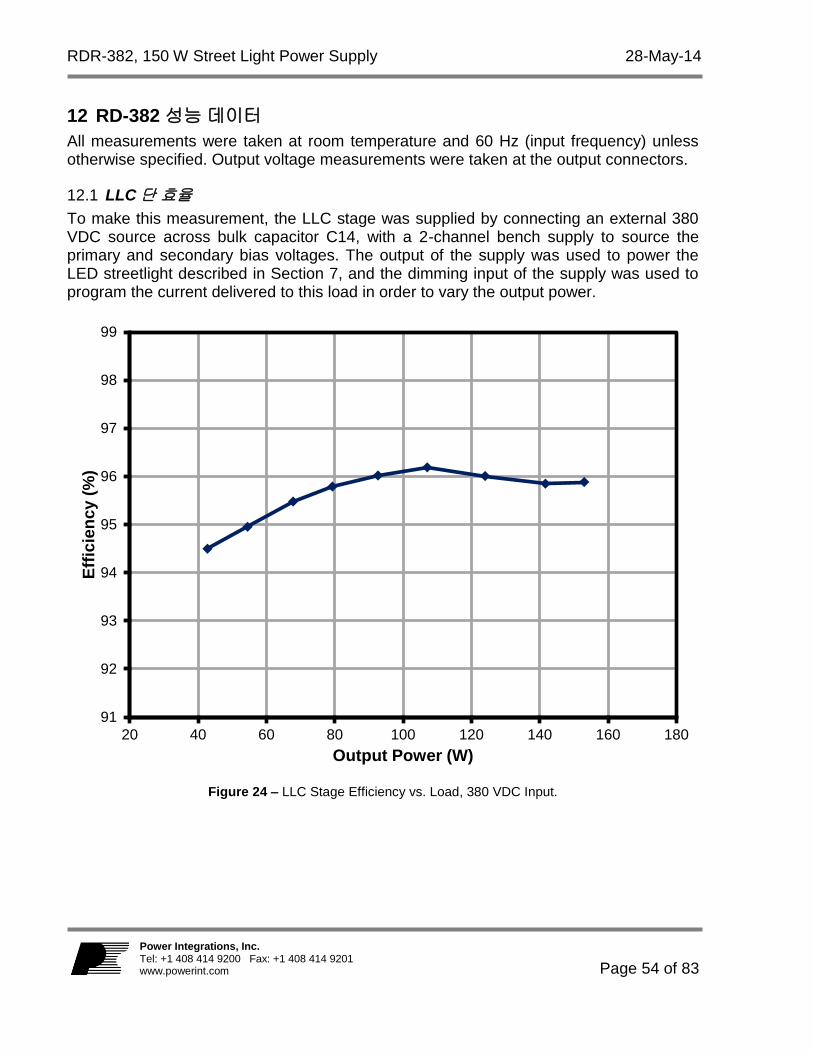
LLC단 효율 12.1
To make this measurement, the LLC stage was supplied by connecting an external 380 VDC source across bulk capacitor C14, with a 2-channel bench supply to source the primary and secondary bias voltages. The output of the supply was used to power the LED streetlight described in Section 7, and the dimming input of the supply was used to program the current delivered to this load in order to vary the output power.
Figure 24 – LLC Stage Efficiency vs. Load, 380 VDC Input.
91
92
93
94
95
96
97
98
99
20 40 60 80 100 120 140 160 180
Eff
icie
nc
y (
%)
Output Power (W)

28-May-14 RDR-382, 150 W Street Light Power Supply
Page 55 of 83
Power Integrations Tel: +1 408 414 9200 Fax: +1 408 414 9201
www.powerint.com
총 효율 12.2
Figures below show the total supply efficiency (PFC and LLC stages). AC input was supplied using a sine wave source. The output was loaded with an electronic load set for constant resistance, with the load adjusted for maximum output current (3.5 A) and 43 V output voltage.
Figure 25 – Total Efficiency vs. Input Voltage, 100% Load.
88
89
90
91
92
93
94
95
70 90 110 130 150 170 190 210 230 250 270 290
Eff
icie
nc
y (
%)
Input Voltage (VAC)

RDR-382, 150 W Street Light Power Supply 28-May-14
Page 56 of 83
Power Integrations, Inc. Tel: +1 408 414 9200 Fax: +1 408 414 9201 www.powerint.com
역률 12.3
Power factor measurements were made using a sine wave AC source and a constant resistance electronic load as described in section 12.2.
Figure 26 – Power Factor vs. Input Voltage, 100% Load.
0.90
0.92
0.94
0.96
0.98
1.00
1.02
1.04
70 90 110 130 150 170 190 210 230 250 270 290
Po
we
r F
acto
r
Input Voltage (VAC)

28-May-14 RDR-382, 150 W Street Light Power Supply
Page 57 of 83
Power Integrations Tel: +1 408 414 9200 Fax: +1 408 414 9201
www.powerint.com
고조파 분포 12.4
Input current harmonic distribution was measured using a sine wave source and an LED load (Section 7).
Figure 27 – Input Current Harmonic Distribution, 230 VAC / 50 Hz Input, 100% Load.
THD, 100% 부하 12.5
THD was measured using the LED streetlight load described in Section 7 of this report.
Input Voltage (VAC) Frequency (Hz) THD (%)
115 60 8.30
230 50 7.38
0.001
0.01
0.1
1
1 2 3 5 7 9 11 13 15 17 19 21 23 25 27 29 31 33 35 37 39
Harm
on
ic C
urr
en
t (A
)
Harmonic Order (n)
MeasuredSpecification Limit

RDR-382, 150 W Street Light Power Supply 28-May-14
Page 58 of 83
Power Integrations, Inc. Tel: +1 408 414 9200 Fax: +1 408 414 9201 www.powerint.com
출력 전류 및 디밍 입력 전압 12.6
Output dimming characteristics were measured using a sine wave AC source and the streetlight LED array described in Section 7. Dimming voltage was provided using a bench supply.
Figure 28 – RD-382 Output Current vs. Dimming Voltage.
0.0
0.5
1.0
1.5
2.0
2.5
3.0
3.5
4.0
0 2 4 6 8 10 12
Ou
tpu
t C
urr
en
t (A
)
Dimming Input (VDC)

28-May-14 RDR-382, 150 W Street Light Power Supply
Page 59 of 83
Power Integrations Tel: +1 408 414 9200 Fax: +1 408 414 9201
www.powerint.com
13 파형
입력 전류, 100% 부하 13.1
Figure 29 – Input Current, 90 VAC, 150 W Load, 2 A, 5 ms / div
Figure 30 – Input Current, 115 VAC, 150 W Load, 2 A, 5 ms / div.
Figure 31 – Input Current, 230 VAC, 150 W Load, 2 A, 5 ms / div.
Figure 32 – Input Current, 265 VAC, 150 W Load, 2 A, 5 ms / div.

RDR-382, 150 W Street Light Power Supply 28-May-14
Page 60 of 83
Power Integrations, Inc. Tel: +1 408 414 9200 Fax: +1 408 414 9201 www.powerint.com
LLC 1차측 전압 및 전류 13.2
The LLC stage current was measured by inserting a current sensing loop in series with the ground side of resonating capacitor C30 that measures the LLC transformer (T2) primary current. The output was loaded with an electronic load set for constant resistance, with the load adjusted for maximum output current and 43 V output voltage.
Figure 33 – LLC Stage Primary Voltage and Current, 100% Load. Upper: Current, 2 A / div. Lower: Voltage, 200 V, 2 s / div.

28-May-14 RDR-382, 150 W Street Light Power Supply
Page 61 of 83
Power Integrations Tel: +1 408 414 9200 Fax: +1 408 414 9201
www.powerint.com
출력 정류기 피크 역방향 전압 13.3
Figure 34 – Output Rectifier (D11) Reverse Voltage, 100% Load. Top and Bottom Traces Show Voltages on Each Half of D11, at
50 V, 2 s / div.
Figure 35 – Output Rectifier (D11) Reverse Voltage, No-Load. Top and Bottom Traces Show Voltages on Each Half of D11, at 50 V,
2 s / div.

RDR-382, 150 W Street Light Power Supply 28-May-14
Page 62 of 83
Power Integrations, Inc. Tel: +1 408 414 9200 Fax: +1 408 414 9201 www.powerint.com
PFC 인덕터 + 스위치 전압 및 전류, 100% 부하 13.4
Since the PFC in this power supply utilizes the internal output diode of the HiperPFS-2, the measured drain current cannot be separated from the PFC inductor current.
Figure 36 – PFC Stage Drain Voltage and Current, Full Load, 115 VAC. Upper: Switch + Inductor Current, 2 A / div. Lower: VDRAIN, 200 V, 2 ms / div.
Figure 37 – PFC Stage Drain Voltage and Current, Full Load, 115 VAC. Upper: Switch + Inductor Current, 2 A / div.
Lower: VDRAIN, 200 V, 20 s / div.
Figure 38 – PFC Stage Drain Voltage and Current, Full Load, 230 VAC. Upper: Switch + Inductor Current, 2 A / div. Lower: VDRAIN, 200 V, 2 ms / div.
Figure 39 – PFC Stage Drain Voltage and Current, Full Load, 230 VAC. Upper: Switch + Inductor Current, 2 A / div.
Lower: VDRAIN, 200 V, 10 s / div.

28-May-14 RDR-382, 150 W Street Light Power Supply
Page 63 of 83
Power Integrations Tel: +1 408 414 9200 Fax: +1 408 414 9201
www.powerint.com
스타트업 시 AC 입력 전류 및 PFC 출력 전압 13.5
Figure 40 – AC Input Current vs. PFC Output Voltage
at Start-up, Full Load, 115 VAC. Upper: AC Input Current, 25 A /div. Lower: PFC Voltage, 100 V, 50 ms / div.
Figure 41 – AC Input Current vs. PFC Output Voltage at Start-up, Full Load, 230 VAC. Upper: AC Input Current, 5 A / div. Lower: PFC Voltage, 200 V, 50 ms / div.
LED 출력 부하 상태에서 LLC 스타트업 출력 전압 및 트랜스포머 1차측 전류 13.6
Figure 42 – LLC Start-up. 115 VAC, 100% Load. Upper: LLC Primary Current, 2 A / div. Lower: LLC VOUT, 20 V, 2 ms / div.

RDR-382, 150 W Street Light Power Supply 28-May-14
Page 64 of 83
Power Integrations, Inc. Tel: +1 408 414 9200 Fax: +1 408 414 9201 www.powerint.com
LED 부하 상태에서 출력 전압/전류 스타트업 13.7
Figure 43 – LLC Start-up. 115 VAC, 100% Load, LED Load. Upper: LLC IOUT, 1 A / div.
Lower: LLC VOUT, 20 V, 2 ms / div.

28-May-14 RDR-382, 150 W Street Light Power Supply
Page 65 of 83
Power Integrations Tel: +1 408 414 9200 Fax: +1 408 414 9201
www.powerint.com
LLC 출력 회로 단락 13.8
The figure below shows the effect of an output short circuit on the LLC primary current and on the output current. A mercury displacement relay was used to short the output to get a fast, bounce-free connection.
Figure 44 – Output Short-Circuit Test. Upper: LLC Primary Current, 2 A / div.
Lower: LLC VOUT, 20 V, 10 s / div.
Figure 45 – Output Short-Circuit Test. Upper: LLC IOUT, 50 A / div.
Lower: LLC VOUT, 20 V, 10 s / div.

RDR-382, 150 W Street Light Power Supply 28-May-14
Page 66 of 83
Power Integrations, Inc. Tel: +1 408 414 9200 Fax: +1 408 414 9201 www.powerint.com
출력 리플 측정 13.9
리플 측정 기술 13.9.1
For DC output ripple measurements a modified oscilloscope test probe is used to reduce spurious signals. Details of the probe modification are provided in the figures below. Tie two capacitors in parallel across the probe tip of the 4987BA probe adapter. Use a
0.1 F / 50 V ceramic capacitor and 1.0 F / 100 V aluminum electrolytic capacitor. The aluminum-electrolytic capacitor is polarized, so always maintain proper polarity across DC outputs.
Figure 46 – Oscilloscope Probe Prepared for Ripple Measurement (End Cap and Ground Lead Removed).
Figure 47 – Oscilloscope Probe with Probe Master 4987BA BNC Adapter (Modified with Wires for Probe Ground for Ripple measurement and Two Parallel Decoupling Capacitors Added).
Probe Tip
Probe Ground

28-May-14 RDR-382, 150 W Street Light Power Supply
Page 67 of 83
Power Integrations Tel: +1 408 414 9200 Fax: +1 408 414 9201
www.powerint.com
리플 측정 13.9.2
Figure 48 – Output Ripple, Full Load, 115 VAC. Upper: IOUT, 1 A / div. Lower: Output Voltage Ripple, 100 mV, 5 ms / div.

RDR-382, 150 W Street Light Power Supply 28-May-14
Page 68 of 83
Power Integrations, Inc. Tel: +1 408 414 9200 Fax: +1 408 414 9201 www.powerint.com
14 온도 프로파일
The board was operated at room temperature, with output set at maximum using a constant resistance load. For each test condition the unit was allowed to thermally stabilize (~1 hr) before measurements were made.
90VAC, 60Hz, 150W 출력, 실온 14.1
Figure 49 – Inrush Limiting Thermistor (RT1), 90 VAC Input, 100% Load, Room Temperature.
Figure 50 – Common Mode Choke (L1), 90 VAC Input, 100% Load, Room Temperature.
Figure 51 – Differential Mode Choke (L4), 90 VAC Input, 100% Load, Room Temperature.
Figure 52 – Input Rectifier Bridge (BR1), 90 VAC Input, 100% Load, Room Temperature.

28-May-14 RDR-382, 150 W Street Light Power Supply
Page 69 of 83
Power Integrations Tel: +1 408 414 9200 Fax: +1 408 414 9201
www.powerint.com
Figure 53 – PFC IC (U1), 90 VAC Input, 100% Load, Room Temperature.
Figure 54 – PFC Inductor (L2), 90 VAC Input, 100% Load, Room Temperature.
Figure 55 – LLC IC (U3), 90 VAC Input, 100% Load, Room Temperature.
Figure 56 – LLC Transformer (T2), 90 VAC Input, 100% Load, Room Temperature.

RDR-382, 150 W Street Light Power Supply 28-May-14
Page 70 of 83
Power Integrations, Inc. Tel: +1 408 414 9200 Fax: +1 408 414 9201 www.powerint.com
Figure 57 – Output Rectifier (D11), 90 VAC Input, 100% Load, Room Temperature.
Figure 58 – Current Sense Resistor (R53), 90 VAC Input, 100% Load, Room Temperature.

28-May-14 RDR-382, 150 W Street Light Power Supply
Page 71 of 83
Power Integrations Tel: +1 408 414 9200 Fax: +1 408 414 9201
www.powerint.com
115VAC, 60Hz, 150W 출력, 실온 14.2
Figure 59 – Inrush Limiting Thermistor (RT1), 115 VAC Input, 100% Load, Room Temperature.
Figure 60 – Common Mode Choke (L1), 115 VAC Input, 100% Load, Room Temperature.
Figure 61 – Differential Mode Choke (L4), 115 VAC Input, 100% Load, Room Temperature.
Figure 62 – Input Rectifier Bridge (BR1), 115 VAC Input, 100% Load, Room Temperature.

RDR-382, 150 W Street Light Power Supply 28-May-14
Page 72 of 83
Power Integrations, Inc. Tel: +1 408 414 9200 Fax: +1 408 414 9201 www.powerint.com
Figure 63 – PFC IC (U1), 115 VAC Input, 100% Load, Room Temperature.
Figure 64 – PFC Inductor (L2), 115 VAC Input, 100% Load, Room Temperature
Figure 65 – LLC IC (U3), 115 VAC Input, 100% Load, Room Temperature.
Figure 66 – LLC Transformer (T1), 115 VAC Input, 100% Load, Room Temperature.

28-May-14 RDR-382, 150 W Street Light Power Supply
Page 73 of 83
Power Integrations Tel: +1 408 414 9200 Fax: +1 408 414 9201
www.powerint.com
Figure 67 – Output Rectifier (D11), 115 VAC Input, 100% Load, Room Temperature.
Figure 68 – Current Sense Resistor (R53), 115 VAC Input, 100% Load, Room Temperature.

RDR-382, 150 W Street Light Power Supply 28-May-14
Page 74 of 83
Power Integrations, Inc. Tel: +1 408 414 9200 Fax: +1 408 414 9201 www.powerint.com
230VAC, 50Hz, 150W 출력, 실온 14.3
Figure 69 – Inrush Limiting Thermistor (RT1), 230 VAC Input, 100% Load, Room Temperature.
Figure 70 – Common Mode Choke (L1), 230 VAC Input, 100% Load, Room Temperature.
Figure 71 – Differential Mode Choke (L4), 230 VAC Input, 100% Load, Room Temperature.
Figure 72 – Input Rectifier Bridge (BR1), 230 VAC Input, 100% Load, Room Temperature.

28-May-14 RDR-382, 150 W Street Light Power Supply
Page 75 of 83
Power Integrations Tel: +1 408 414 9200 Fax: +1 408 414 9201
www.powerint.com
Figure 73 – PFC IC (U1), 230 VAC Input, 100% Load, Room Temperature.
Figure 74 – PFC Inductor (L2), 230 VAC Input, 100% Load, Room Temperature
Figure 75 – LLC IC (U3), 230 VAC Input, 100% Load, Room Temperature.
Figure 76 – LLC Transformer (T1), 230 VAC Input, 100% Load, Room Temperature.

RDR-382, 150 W Street Light Power Supply 28-May-14
Page 76 of 83
Power Integrations, Inc. Tel: +1 408 414 9200 Fax: +1 408 414 9201 www.powerint.com
Figure 77 – Output Rectifier (D11), 230 VAC Input, 100% Load, Room Temperature.
Figure 78 – Current Sense Resistor (R53), 230 VAC Input, 100% Load, Room Temperature.

28-May-14 RDR-382, 150 W Street Light Power Supply
Page 77 of 83
Power Integrations Tel: +1 408 414 9200 Fax: +1 408 414 9201
www.powerint.com
15 출력 게인-위상
Gain-phase was tested a maximum load using the constant voltage load described in Section 7.1. It is important to use the actual LED load or a load with similar characteristics during gain-phase testing, as a load with different output characteristic will yield inaccurate results.
Figure 79 – LLC Converter Gain-Phase, 100% Load Crossover Frequency – 1.5 kHz, Phase Margin - 66°.

RDR-382, 150 W Street Light Power Supply 28-May-14
Page 78 of 83
Power Integrations, Inc. Tel: +1 408 414 9200 Fax: +1 408 414 9201 www.powerint.com
16 전도성 EMI
Conducted EMI tests were performed using the constant voltage load described in Section 7.1. The output return was connected to the LISN artificial hand to simulate the capacitance of a typical set of LED panels to chassis ground. The step change in readings at 80 MHz is due to an automatic 10 dB scale change of the EMI receiver rather than an actual peak at 80 MHz.
Figure 80 – Conducted EMI, 115 VAC, Full Load.

28-May-14 RDR-382, 150 W Street Light Power Supply
Page 79 of 83
Power Integrations Tel: +1 408 414 9200 Fax: +1 408 414 9201
www.powerint.com
Figure 81 – Conducted EMI, 230 VAC, Full Load.

RDR-382, 150 W Street Light Power Supply 28-May-14
Page 80 of 83
Power Integrations, Inc. Tel: +1 408 414 9200 Fax: +1 408 414 9201 www.powerint.com
17 라인 서지 테스트
라인 서지 테스트 설정 17.1
The picture below shows the power supply set-up for surge testing. The supply is placed on a ground plane approximately the size of the power supply. A piece of single-sided copper clad printed circuit material was used in this case, but a piece of aluminum sheet with appropriate insulation would also work. An IEC AC connector was wired to the power supply AC input, with the safety ground connected to the ground plane. The CV output load (described in section 7) was placed on top of the ground plane so that it would capacitively couple to the safety ground. A 48 V fan was located inside the plastic shroud shown in the figure, and used to cool the CV load during testing. An indicator consisting of a GaP yellow-green led in series with a 39 V Zener diode and a 100 ohm resistor was placed across the output of the supply and used as a sensitive output dropout detector during line surge testing. The UUT was tested using a Teseq NSG 3060 surge tester. Results of common mode and differential mode surge testing are shown below. A test failure was defined as a non-recoverable output interruption requiring supply repair or recycling AC input voltage.
Figure 82 – Line Surge Physical Set-up.

28-May-14 RDR-382, 150 W Street Light Power Supply
Page 81 of 83
Power Integrations Tel: +1 408 414 9200 Fax: +1 408 414 9201
www.powerint.com
디퍼렌셜 모드 서지, 1.2/50sec 17.2
AC Input Voltage (VAC)
Surge Voltage (kV)
Phase Angle (º)
Generator Impedance
()
Number of Strikes
Test Result
115 +2 90 2 10 PASS
115 -2 90 2 10 PASS
115 +2 270 2 10 PASS
115 -2 270 2 10 PASS
115 +2 0 2 10 PASS
115 -2 0 2 10 PASS
AC Input Voltage (VAC)
Surge Voltage (kV)
Phase Angle (º)
Generator Impedance
()
Number of Strikes
Test Result
230 +2 90 2 10 PASS
230 -2 90 2 10 PASS
230 +2 270 2 10 PASS
230 -2 270 2 10 PASS
230 +2 0 2 10 PASS
230 -2 0 2 10 PASS
커먼 모드 서지, 1.2/50sec 17.3
AC Input Voltage (VAC)
Surge Voltage (kV)
Phase Angle (º)
Generator Impedance
()
Number of Strikes
Test Result
115 +4 90 12 10 PASS
115 -4 90 12 10 PASS
115 +4 270 12 10 PASS
115 -4 270 12 10 PASS
115 +4 0 12 10 PASS
115 -4 0 12 10 PASS
AC Input Voltage (VAC)
Surge Voltage (kV)
Phase Angle (º)
Generator Impedance
()
Number of Strikes
Test Result
230 +4 90 12 10 PASS
230 -4 90 12 10 PASS
230 +4 270 12 10 PASS
230 -4 270 12 10 PASS
230 +4 0 12 10 PASS
230 -4 0 12 10 PASS

RDR-382, 150 W Street Light Power Supply 28-May-14
Page 82 of 83
Power Integrations, Inc. Tel: +1 408 414 9200 Fax: +1 408 414 9201 www.powerint.com
18 개정 내역
Date Author Revision Description and Changes Reviewed
04-Mar-14 RH 6.1 Initial Release Apps & Mktg
28-May-14 RH 6.2 Schematic Updated

28-May-14 RDR-382, 150 W Street Light Power Supply
Page 83 of 83
Power Integrations Tel: +1 408 414 9200 Fax: +1 408 414 9201
www.powerint.com
최신 업데이트에 대한 자세한 내용은 당사 웹사이트(www.powerint.com)를 참고하십시오.
파워 인테그레이션스(Power Integrations)는 안정성 또는 생산성 향상을 위하여 언제든지 당사 제품을 변경할 수 있는
권한이 있습니다. 파워 인테그레이션스(Power Integrations)는 여기서 설명하는 디바이스나 회로 사용으로 인해
발생하는 어떠한 책임도 지지 않습니다. 파워 인테그레이션스(Power Integrations)는 어떠한 보증도 제공하지 않으며
모든 보증(상품성에 대한 묵시적 보증, 특정 목적에의 적합성 및 타사 권리의 비침해를 포함하되 이에 제한되지 않음)을
명백하게 부인합니다.
특허 정보
여기에 설명한 제품 및 애플리케이션(제품의 외장 트랜스포머 구성 및 회로 포함)은 하나 이상의 미국 및 해외 특허의
대상이 되거나 파워 인테그레이션스(Power Integrations)에서 출원 중인 미국 및 해외 특허 신청의 대상이 될 수
있습니다. 파워 인테그레이션스(Power Integrations)의 전체 특허 목록은 www.powerint.com에서 확인할 수 있습니다.
파워 인테그레이션스(Power Integrations)는 고객에게 http://www.powerint.com/ip.htm.에 명시된 특정 특허권에 따라
라이센스를 부여합니다.
PI 로고, TOPSwitch, TinySwitch, LinkSwitch, LYTSwitch, DPA-Switch, PeakSwitch, CAPZero, SENZero, LinkZero, HiperPFS,
HiperTFS, HiperLCS, Qspeed, EcoSmart, Clampless, E-Shield, Filterfuse, StackFET, PI Expert 및 PI FACTS 는 Power
Integrations, Inc의 상표입니다. 다른 상표는 각 회사 고유의 자산입니다. ©Copyright 2013 Power Integrations, Inc.
파워 인테그레이션스(Power Integrations) 전 세계 판매 지원 지역
세계 본사
5245 Hellyer Avenue San Jose, CA 95138, USA.
본사 전화: +1-408-414-9200
고객 서비스:
전화: +1-408-414-9665
팩스: +1-408-414-9765
전자 메일:
독일
Lindwurmstrasse 114 80337, Munich Germany
전화: +49-895-527-39110
팩스: +49-895-527-39200
전자 메일:
일본
Kosei Dai-3 Building 2-12-11, Shin-Yokohama, Kohoku-ku, Yokohama-shi, Kanagawa 222-0033 Japan
전화: +81-45-471-1021
팩스: +81-45-471-3717
전자 메일:
대만
5F, No. 318, Nei Hu Rd., Sec. 1 Nei Hu District Taipei 11493, Taiwan R.O.C.
전화: +886-2-2659-4570
팩스: +886-2-2659-4550
전자 메일:
중국(상하이)
Rm 2410, Charity Plaza, No. 88,
North Caoxi Road,
Shanghai, PRC 200030
전화: +86-21-6354-6323
팩스: +86-21-6354-6325
전자 메일:
인도
#1, 14th Main Road
Vasanthanagar Bangalore-560052 India
전화: +91-80-4113-8020
팩스: +91-80-4113-8023
전자 메일:
한국
RM 602, 6FL Korea City Air Terminal B/D, 159-6 Samsung-Dong, Kangnam-Gu, Seoul, 135-728 Korea
전화: +82-2-2016-6610
팩스: +82-2-2016-6630
전자 메일:
유럽 본사
1st Floor, St. James’s House East Street, Farnham Surrey GU9 7TJ United Kingdom
전화: +44 (0) 1252-730-141 팩스: +44 (0) 1252-727-689
전자 메일:
중국(센젠)
3rd Floor, Block A,
Zhongtou International Business
Center, No. 1061, Xiang Mei Rd,
FuTian District, ShenZhen,
China, 518040
전화: +86-755-8379-3243
팩스: +86-755-8379-5828
전자 메일:
이탈리아
Via Milanese 20, 3rd. Fl.
20099 Sesto San Giovanni (MI) Italy
전화: +39-024-550-8701
팩스: +39-028-928-6009
전자 메일:
싱가포르
51 Newton Road, #19-01/05 Goldhill Plaza Singapore, 308900
전화: +65-6358-2160
팩스: +65-6358-2015
전자 메일:
애플리케이션 문의 전화
전 세계 통합 번호 +1-408-
414-9660
애플리케이션 문의 팩스
전 세계 통합 번호 +1-408-
414-9760


![04장[1].직류 바이어스 방법 BJT IV](https://static.fdocument.pub/doc/165x107/54649afdb4af9fd1478b4f9e/041-bjt-iv.jpg)