![FluorescenceMicroscopyFluorescence Microscopy PlidLihtMiPolarized Light Microscopyolympus114.com/ctlg/6[1]. 현미경 관찰법(형광... · · 2008-11-21형광관찰법(Fluorescence](https://static.fdocument.pub/doc/165x107/5aa04c4d7f8b9a6c178dde89/fluorescencemicroscopyfluorescence-microscopy-plidlihtmipolarized-light-1-.jpg)
High-Speed Confocal Fluorescence Microscopy Using a …
6
Bioimages 4 (2): 57-62, June 1996. ©1996 by Bioimaging Society High-Speed Confocal Fluorescence Microscopy Using a Nipkow Scanner with Microlenses for 3-D Imaging of Single Fluorescent Molecule in Real Time Akira lchihara 1 *, Takeo Tanaami2, Katsumi lsozaki2, Yumiko Sugiyama 2 , Yasuhito Kosugi2, Kenta Mikuriya 2 , Michio Abe3, lsao Uemura 3 1 Yokogawa Research Institute Corp., 2-9-32 Nakacho, Musashino-shi, Tokyo 180, 2 Sensor Laboratory, Yokogawa Electric Corp., 2-9-32 Nakacho, Musashino-Shi, Tokyo 180, and 3 Department of Biology, Tokyo Metropolitan University, 1-1 Minami-Osawa, Hachioji-shi, Tokyo 192-03, Japan. Summary Recent developments in confocal fluorescent microscopy have made 3-D observation of biological specimens possible, an epoch-making event in the long history of microscopy. However, most confocal microscopes currently used are insufficient for the observation of living cells and organs, which require real-time observations with minimal fluorescence staining. We have developed an innovative Nipkow- type scanner for a confocal microscope in which a microlens array is placed in front of a pinhole array and thus the optical efficiency of high-speed scanning is improved. Scanning speeds of 1,000 frames/sec are attained with 10-1000 times greater SIN than those of conventional confocal micro- scopes. Key words Confocal fluorescence microscope, Nipkow scanner, micro- lens, real-time 3-D imaging, living cell observation Introduction The principle of confocal fluorescence microscopy is measuring the intensity of fluorescence in 3-D space for each point in a specimen. There are several types of confocal microscopes, which scan the specimen with light beams in different ways. However, it takes nearly one second to optically scan one 2-D frame using a conventional confocal microscope, and this is too slow to observe movement of living cells in real time. For example, studies of the response of the nervous system indicate that a speed of one frame per millisecond is desirable. In addition to the speed, it is also necessary to attain high resolution. Recently, two Japanese groups (Sase et al., 1995, 1996; Funatsu et al., 1995) achieved great success with fluorescence microscopy at a molecular level, due to large reduction of the background light in their observation systems. In particular, Sase et al. developed a 3-D observation system that attained a signal-to-background ratio 1,000 times that of conven- tional fluorescence microscopes. This system can be adopted for confocal microscopy. In this paper, we describe the development of a high-speed confocal scanner and report its performance. Materials and Methods Construction of CSU1 O Figure 1 shows an overview of the construction of our scanner (Model CSUlO). Model CSUlO had two disks; light incident on microlenses in the upper disk was focused by the microlenses on corresponding pinholes on the lower disk. This system was based on the Nipkow disk scanner, which was invented by Paul Nipkow in 1884 as an optical scanner using rotation of a disk with pinholes to produce an image. The Nipkow disks were used at both the camera and the monitor in the first stage of the development of television (Mellors and Silver, 1951; Zvorykin and Ramberg, 1961). While a Nipkow disk retains many advantages such as fast scanning speed and simple construction, its illumi- nation efficiency is very low due to very low area ratio of the pinhole apertures to the disk surface. Moreover, in a conventional Nipkow disk scanner the detector is placed on the light-source side of the pinhole array, which results in high background light (flare) and thus low SIN. In our system, about 20,000 microlenses in the upper disk focused collimated light from a laser on corre- sponding pinholes in the lower disk which were ar- ranged in the same pattern as the microlenses on the upper disk. Due to the microlenses, the pinholes effec- tively collected 40% of the light incident on the surface of the upper disk. The light passing through the pin- holes was focused by an objective lens on a spot in the specimen. Fluorescent light from the specimen re- *To whom all correspondence should be addressed. 57
Transcript of High-Speed Confocal Fluorescence Microscopy Using a …

Bioimages 4 (2): 57-62, June 1996. ©1996 by Bioimaging Society
High-Speed Confocal Fluorescence Microscopy Using a Nipkow Scanner with Microlenses for 3-D Imaging of Single Fluorescent Molecule in Real Time
Akira lchihara1*, Takeo Tanaami2, Katsumi lsozaki2, Yumiko Sugiyama2, Yasuhito Kosugi2,
Kenta Mikuriya2, Michio Abe3, lsao Uemura3
1Yokogawa Research Institute Corp., 2-9-32 Nakacho, Musashino-shi, Tokyo 180, 2Sensor Laboratory, Yokogawa Electric Corp., 2-9-32 Nakacho, Musashino-Shi, Tokyo 180, and 3Department of Biology, Tokyo Metropolitan University, 1-1 Minami-Osawa, Hachioji-shi, Tokyo 192-03, Japan.
Summary
Recent developments in confocal fluorescent microscopy have made 3-D observation of biological specimens possible, an epoch-making event in the long history of microscopy. However, most confocal microscopes currently used are insufficient for the observation of living cells and organs, which require real-time observations with minimal fluorescence staining. We have developed an innovative Nipkowtype scanner for a confocal microscope in which a microlens array is placed in front of a pinhole array and thus the optical efficiency of high-speed scanning is improved. Scanning speeds of 1,000 frames/sec are attained with 10-1000 times greater SIN than those of conventional confocal microscopes.
Key words
Confocal fluorescence microscope, Nipkow scanner, microlens, real-time 3-D imaging, living cell observation
Introduction
The principle of confocal fluorescence microscopy is measuring the intensity of fluorescence in 3-D space for each point in a specimen. There are several types of confocal microscopes, which scan the specimen with light beams in different ways. However, it takes nearly one second to optically scan one 2-D frame using a conventional confocal microscope, and this is too slow to observe movement of living cells in real time. For example, studies of the response of the nervous system indicate that a speed of one frame per millisecond is desirable.
In addition to the speed, it is also necessary to attain high resolution. Recently, two Japanese groups (Sase et al., 1995, 1996; Funatsu et al., 1995) achieved great success with fluorescence microscopy at a molecular level, due to large reduction of the background light in their observation systems. In particular, Sase et al.
developed a 3-D observation system that attained a signal-to-background ratio 1,000 times that of conventional fluorescence microscopes. This system can be adopted for confocal microscopy. In this paper, we describe the development of a high-speed confocal scanner and report its performance.
Materials and Methods
Construction of CSU1 O
Figure 1 shows an overview of the construction of our scanner (Model CSUlO). Model CSUlO had two disks; light incident on microlenses in the upper disk was focused by the microlenses on corresponding pinholes on the lower disk. This system was based on the Nipkow disk scanner, which was invented by Paul Nipkow in 1884 as an optical scanner using rotation of a disk with pinholes to produce an image. The Nipkow disks were used at both the camera and the monitor in the first stage of the development of television (Mellors and Silver, 1951; Zvorykin and Ramberg, 1961). While a Nipkow disk retains many advantages such as fast scanning speed and simple construction, its illumination efficiency is very low due to very low area ratio of the pinhole apertures to the disk surface. Moreover, in a conventional Nipkow disk scanner the detector is placed on the light-source side of the pinhole array, which results in high background light (flare) and thus low SIN.
In our system, about 20,000 microlenses in the upper disk focused collimated light from a laser on corresponding pinholes in the lower disk which were arranged in the same pattern as the microlenses on the upper disk. Due to the microlenses, the pinholes effectively collected 40% of the light incident on the surface of the upper disk. The light passing through the pinholes was focused by an objective lens on a spot in the specimen. Fluorescent light from the specimen re-
*To whom all correspondence should be addressed .
57

lchihara et al.
turned along the same path through the objective lens and pinhole, and was reflected by a dichroic mirror through a relay lens to the imaging point in a camera. The upper disk containing the microlenses was mechanically connected to the lower disk containing the pinholes, and both were rotated by an electrical motor, thus the light beams raster-scanned the specimen.
Photographs of sea urchin embryo (Uemura and Abe,
1995)
Sea urchin embryos at gastrula invagination stage were treated with dispase, washed with sea water, extracted in a buffer solution containing surfactants, and fixed with formaldehyde. Monoclonal anti-tubulin antibody (Amersham) was used as the first probe for tubulin . Embryos were then stained with a secondary antibody, BODIPY-FL-labeled anti-mouse IgG antibody (Molecular Probes). An argon laser with a 488 nm line wavelength was used for excitation, and photographs were taken through an FITC filter. The magnification of the objective lens was x 40, and ASA 1600 film was used.
3-D Image of sea urchin embryonic structure
The 3-D images of sea urchin embryos were reconstructed from the optical sections taken by CSUlO using an image analyzer software: Insight IQ System (Meridian).
Results
Because of its fast scanning rate at 360 frames/second and its high light efficiency, CSUlO enabled direct viewing of confocal images. Moreover, its high SIN enabled direct view observation of specimens which showed only weak fluorescence. Immunofluorescent microscopic images of sea urchin embryos at the gastrula invagination stage are shown in Fig. 2. P 1 shows a confocal microscopic section in which microtubules of gut cells invaginated inside the blastocoel are clearly shown. In addition, alignment of the microtubules inside the columnar ectodermal cells along the contour of each cell is shown distinctly . It is also clearly seen that cilia arising outside the embryos are connected to the microtubules inside the cells through the basal body at the base. Parts of the spindle microtubules of dividing cells are also shown. P2 shows the surface of an embryo with sections of microtubules aligned along the contour of each ectodermal cell interconnected to form a honeycomb structure. The hole in the center is a blastopore. P3 and P4 were taken at the same spot as P2, but the focus was gradually shifted along the z-axis to scan the inside so that gastrula cross-section and mesenchyme cells inside the blastocoel can be observed.
58
Laser
I Rotation I I
M1crolens ~ 'I' Array !
Microlens
~ l'I~~
---------i-~J~-~( --+r-uq l 1-1 __ -- -~- ---t~ , ~ ~ Lens Camera
' - - - ' Pinhole Pinhole Array
Objective Lens
Sample
Fig. I. Overview of CSUIO. About 20,000 microlenses in the upper disk focused co llim ated light from a laser on corresponding pinholes in the lower disk which were arranged in the same pattern as the
microlenses on the upper disk. The li ght pass ing through the pinholes
was focused by an objective lens on a spot in the speci men.
Fluorescent light from the specimen returned along the same path
through the objective lens and the pinhole, and was reflected by a
dichroic mirror through a relaying lens to the im aging point in a
camera. The upper disk was mechanica lly connected to the lower di sk, and both were rotated by a motor; thus the li ght beams raster-scanned the specimen.
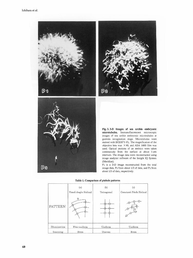
Figure 3 shows 3-D images of sea urchin embryos. Optical sections of sea urchin embryos were continuously taken by using CSUlO, and the 3-D image was reconstructed using an image analyzer software: Insight IQ System (Meridian). P1 was reconstructed from the total image data and clearly shows the alignment of microtubules inside the cell. P2 was reconstructed with about 1/3 of the data taken from the embryo height, and P3 shows a 3-D image of only the cilia on the embryo surface reconstructed from about 1/5 of the data of the embryo height.
Discussion
The pinhole pattern on our Nipkow disk was designed so that excitation light beams uniformly scanned a whole plane of the specimen. This design had all the advantages and none of the defects of the conventional Nipkow scanner. Some special features of our system are as follows:
High Speed Scanning with Multibeam
To microscopically observe a living biological specimen in real time, high-speed scanning is required.

High-Speed Confocal Fluorescence Microscopy
Fig. 2. Immunofluorescent microscopic images of sea urchin embryonic microtubules at gastrnla invagination stage. Mi crotubul es were stained with BODIFY-FL. The magnifi cation of the objecti ve lens was x 40, and ASA 1600 film was used. P1 is a central section of an embryo. P2 to P4 are the images of an embryo taken at the same spot but gradually shifting the z-axis focusing from th e surfa ce (P2) to the 2/3 depth from the surface (P 4).
Especially when using confocal microscopy for 3-D imaging, the scanning rate must be 10 to 100 times as fast as for 2-D imaging. The Galvanometer-type scanner is a single-beam scanner, whereas the Nipkow type is a multibeam scanner. In our scanner, pinholes are placed on an array with 250 µm separation from each other; i.e., there are 1,000 beams within one 7 x 10 mm visual frame. As a consequence, for a given beam scanning velocity, our system realizes 1,000 times the imaging speed of the Galvanometer-type scanner.
Constant Rotation
A Galvanometer mirror oscillates from side to side the scan velocity is non-linear - and the scan velocity at both ends of the span is zero. In contrast, a rotatingdisk scanner scans with a constant velocity, so that a stable high-speed scanning can be achieved.
Insensitivity to Vibration
Mechanical vibration caused by bearings or other parts of an electrical motor or Galvanometer mirror can be a big problem. However, as shown in Fig. 1, in our system the focal point of the excitation beam which impinges onto the pinhole is far enough away (the focal point is at the back of the observation Jens) that pinhole-plate vibration of up to 1 mm is permissible, and thus the effects of vibration in the axial direction are negligible. Moreover, in the common path system we employed, the excitation light beam and the reflected beam pass through the same pinhole even when vibration in the radial direction occurs. Thus the Nipkow-type scanner is very suitable for high-speed scanning. The Nipkow disk in the CSUlO is designed to scan 12 frames in one rotation, and rotates at 1,800 rpm; thus its resolution velocity is 1/360 sec per frame.
59
lchihara et al.
PATTERN
Illumination
Scanning
60
Fig. 3. 3-D Images of sea urchin embryonic microtubules. lmm unofluorescent microscopic images of sea urchin embryonic microtubules at gastrula invagination stage. Microtubules were stained with BODIFY-FL. The magnification of the objective lens was X 40, and ASA 1600 fi lm was used. Optical sections of an embryo were taken continuously from the surface at about I µm intervals. The image data were reconstructed using image analyzer software of the Insight IQ System (Meridian) . P 1 is a 3-D image reconstructed from the total image data, P2 from about 1/3 of data, and P3 from about 1/5 of data, respectively.
Table l. Comparison of pinhole patterns
(a) (b) (c)
Fixed-Angle Helical Tetragonal Constant-Pitch Helical
~ i e--e--,e-- 0
/~ szI8_!-0-
Non-uniform Uniform Uniform
Even Uneven Even

In theory we can achieve higher velocity by further increasing motor rotation velocity-using high-speed motors such as ballbearing motors which can run at 20,000 rpm or air-bearing motors with even higher speed. However, the durability of the scanning system as a whole has to be considered as well.
Low background light
The key to microscopic observation of molecules whose fluorescence emission is very weak lies in minimizing background signals (or flare) and maximizing the SIN of the system. To attain this, light from the excitation source should not impinge on the detector. It is possible to stop the excitation light beam from impinging on the detector by using an improved barrier filter, but it is impossible to remove light generated inside the system if its wavelength is within the detection range; i.e., the most fundamental issue is to design a system which is free from fluorescence. Unfortunately, it is impossible to manufacture a system with completely fluorescence-free materials. In CSUlO, we manufactured such fundamental glass parts as the microlens array, pinhole array and dichroic mirror with synthetic quartz and succeeded in minimizing the fluorescent light inside the system, thus improving the SIN greatly.
While CSUlO is an innovative confocal scanner which attained high-speed and good resolution, a number of issues still need to be explored to further improve CSUlO and to attain our final target of observing one molecule in real time. Some of the most important issues are as follows:
Image distortion and non-uniformity in light intensity distribution
The spatial accuracy of a scanner has to be much higher than the resolution of a microscope. The main causes of image distortion in scanning-type microscopy are scanning distortion and non-uniformity in light intensity distribution.
The following qualitative factors affect uniformity of illumination in our scanner:
Arrangement of pinhole and microlens pattern
It is essential for a Nipkow disk type scanner to have a pinhole pattern which theoretically gives uniform image. One of the special features of our scanner is its small size and small scanning distortion, which was achieved by using a constant-pitch helical pattern. In Table 1 the pattern we used is compared with conventional patterns. Traditionally, the fixed-angle helical pattern (a) has been mostly used due to its simplicity. Its disadvantage is that the light intensity at the outside
High-Speed Confocal Fluorescence Microscopy
periphery of the disk is lower than that at the inside periphery since the pitch between pinholes gets wider towards the outside periphery of the disk. To lessen the effects of non-uniform illumination, it is necessary to make the disk large enough that illumination at the outside periphery of the disk is still sufficient. With a tetragonal pattern (b ), there is no imbalance in light intensity between the inside and the outside peripheries of the disk; however, when the disk is rotated, scanning pitch is not constant, resulting in fringes (stripes). The constant pitch helical pattern ( c) is designed with equal pitch along the helical pattern of pinholes (peripheral pitch) and equal track pitch of the helical pattern (radial pitch) so as to give constant illumination and also constant scanning pitch regardless of the radius. As a result, there is almost no distortion with this pattern.
Manufacturing variations in the pinhole array and microlens array
The original molds for pinhole and microlens arrays were manufactured using steppers such as used in semiconductor manufacturing. Current steppers have positioning accuracy better than 0.1 µm, so we can expect - in the worst case - 0.5 µm variation. In our system, the primary image is focused on the pinhole array by the objective lens, which means that this variation corresponds to 50 nm on the specimen with a x 10 objective lens, and 5 nm with a x 100 objective lens, respectively; these are small enough to be considered negligible.
Non-uniformity of illumination caused by rotation-related problems
When the rotation center does not fall exactly on the pinhole array center, the illumination becomes nonuniform. Variation of rotation locus of the motor can be represented by "runout". We are currently using a ballbearing motor with a runout of several µm. An air-bearing motor may give better results. Currently, the static rotation eccentricity of our system is about 10 µm , which needs to be improved in future. On the other hand, variation caused by rotation could be statistically reduced by integrating numbers of image data. We designed the pinhole pattern to scan 12 frames per rotation. As the motor rotates at 1,800 rpm, we observe one image which is actually the integration of 12 scanning frames at the video rate (1130 sec per frame). Thus illumination non-uniformity caused by rotation is averaged out at the video rate. However, for faster scanning, we may need to increase the rotation speed to a level higher than 10,000 rpm, and a loweccentricity design may become more important.
61

lchihara et al.
Alignment of microlens array and pinhole array
As shown in Fig. 1, positional alignment and fixing of the microlens array and the pinhole array is one of our key technologies. In fact, each of more than 20,000 microlenses has to be aligned one by one with at an accuracy of several µm with pinholes. To date, we have manufactured ten units with satisfactory results, but we have not determined specifications for matching accuracy yet. We need to examine how to measure the variation in each light beam and how to maintain accuracy. We have to decide whether to reduce illumination imbalance by choosing higher-speed rotation and integrating more images or to make illumination during each rotation more uniform.
Received March 13 1996; revised June 3 1996.
Referrences
Funatsu, T., Harada, Y., Tokunaga, M., Saito, K. and Yanagida, T. (1995). Imaging of single fluorescent
62
molecules and individual ATP turnovers by single myosin molecules in aqueous solution. Nature, 374: 555-559.
Mellors, RC. and Silver, R. (1951). A microfluorometric scanner for the differential detection of cells: Application to exfoliative cytology. Science, 114: 356-360.
Sase, I., Miyata, H., Corrie, J.E.T., Craik, J.S . and Kinoshita, K. (1995). Real time imaging of single fluorophores on moving actin with an epifluorescence microscope. Biophysical J., 69: 323-328.
Sase, I. , Corrie, J.E.T., Craik, J.S. and Kinoshita, K. Jr. (1996). Realtime imaging of the orientation of a single dye molecule. Bioimages, 4: 36.
Uemura, I. and Abe, M. (1995). The z-axis Resolution in the confocal laser scanning microscopy. The Second Internet World Congress on Biomedical Science '95, http://medic.mie-u.ac.jp/2NTCNG/POSTERS/FP0616.
Zvorykin, V.K. and Ramberg, E.G. (1961). Photoelectricity and Its Applications (John Wiley , New York), 4th Ed. Chap. , 16: 366-367.