High-rise Design - Hot Water Recirculations and General Pumping Practices
156
Domestic Hot Water Recirculation James M. Pleasants Company www.jmpco.com Approved by GBCI for 1 CE Hour Course Approval Number is 0090009310
Transcript of High-rise Design - Hot Water Recirculations and General Pumping Practices

Domestic Hot Water Recirculation
James M. Pleasants Company
www.jmpco.com
Approved by GBCI for 1 CE Hour
Course Approval Number is 0090009310
Domestic Hot Water Recirculation Learning Objectives
In this seminar you will learn to: 1. Describe why conserving water is important.
2. Calculate the recirculation flow rate.
3. Identify recirculation trouble areas.
4. Design a recirculation system with a sizing example.
5. Apply special design considerations for instantaneous water heater
applications.
6. Identify ways to balance multiple riser flows.
7. Identify ways to recirculate buildings with pressure reducing valve.
2

Building Return
Cold Water Supply
Lochinvar Armor Condensing Water Heater
Constant Flow Pump Balance
Valve
Recirculation Pump
Lock-Temp Storage Tank
Drain
Building Hot Water
Supply
Relief Valve
Thermal Expansion
Tank
Backflow Preventor
Condensing Water Heater
070709CE
3

Why?
4
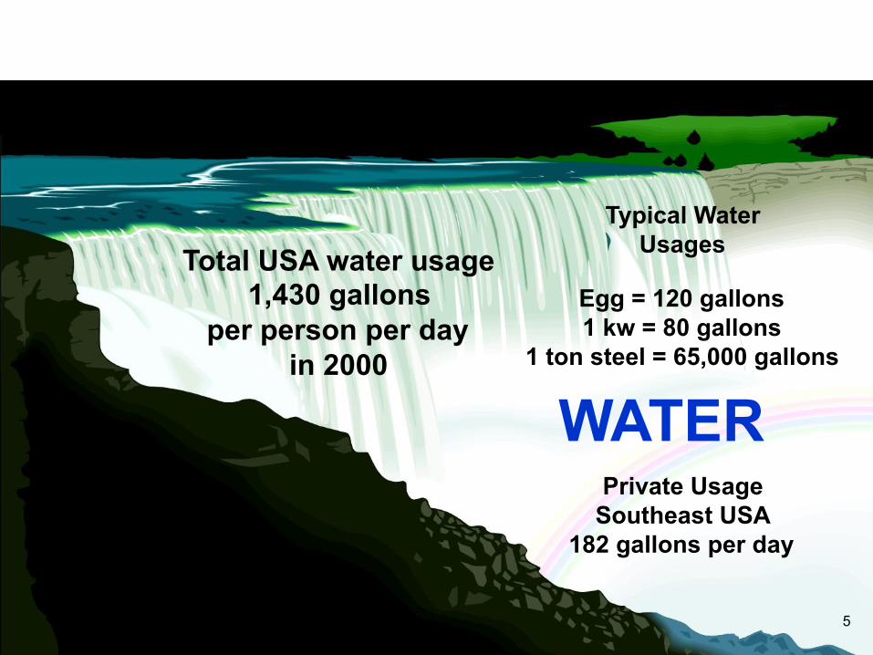
WATER
Egg = 120 gallons 1 kw = 80 gallons
1 ton steel = 65,000 gallons
Typical Water Usages Total USA water usage
1,430 gallons per person per day
in 2000
Private Usage Southeast USA
182 gallons per day
5

WATER
6

Water covers more than
70% of the
earth’s surface.
about 97% is salty water
3% fresh water
World Population
1802 1 Billion 2000 6 Billion 2040 9 Billion
7

What Is The Purpose of Hot Water Recirculation?
To Conserve Water By Providing Hot Water At The Fixture
More Quickly
8
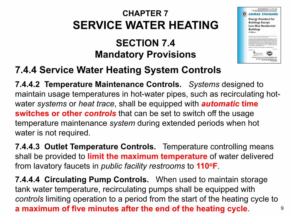
CHAPTER 7 SERVICE WATER HEATING
7.4.4 Service Water Heating System Controls
SECTION 7.4 Mandatory Provisions
7.4.4.2 Temperature Maintenance Controls. Systems designed to maintain usage temperatures in hot-water pipes, such as recirculating hot-water systems or heat trace, shall be equipped with automatic time switches or other controls that can be set to switch off the usage temperature maintenance system during extended periods when hot water is not required.
7.4.4.3 Outlet Temperature Controls. Temperature controlling means shall be provided to limit the maximum temperature of water delivered from lavatory faucets in public facility restrooms to 110oF.
7.4.4.4 Circulating Pump Controls. When used to maintain storage tank water temperature, recirculating pumps shall be equipped with controls limiting operation to a period from the start of the heating cycle to a maximum of five minutes after the end of the heating cycle. 9
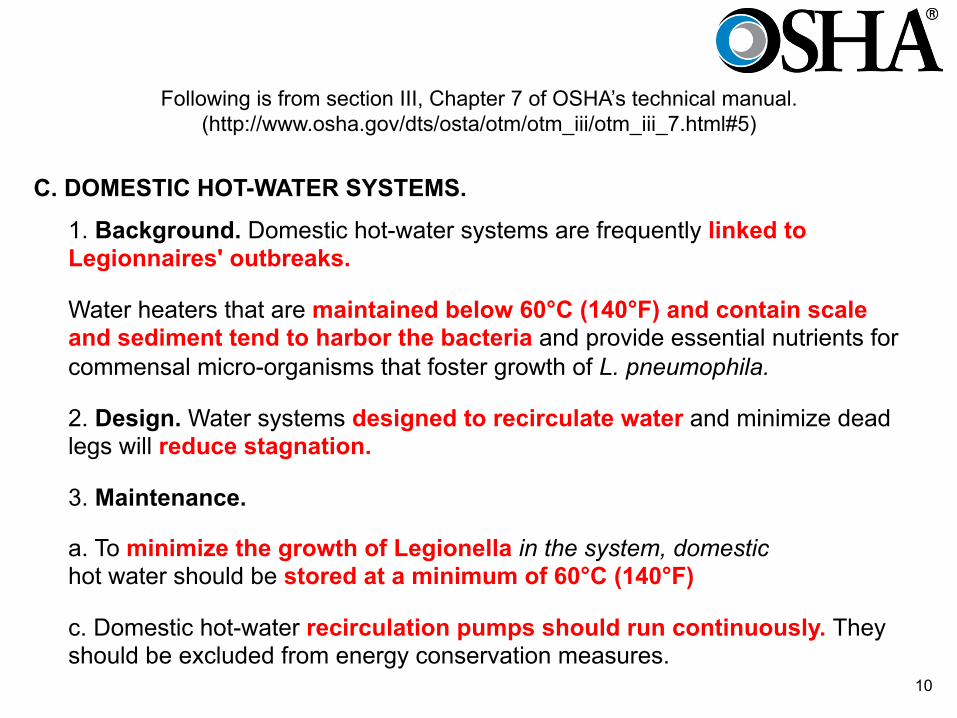
Following is from section III, Chapter 7 of OSHA’s technical manual. (http://www.osha.gov/dts/osta/otm/otm_iii/otm_iii_7.html#5)
1. Background. Domestic hot-water systems are frequently linked to Legionnaires' outbreaks.
C. DOMESTIC HOT-WATER SYSTEMS.
2. Design. Water systems designed to recirculate water and minimize dead legs will reduce stagnation.
3. Maintenance.
c. Domestic hot-water recirculation pumps should run continuously. They should be excluded from energy conservation measures.
Water heaters that are maintained below 60°C (140°F) and contain scale and sediment tend to harbor the bacteria and provide essential nutrients for commensal micro-organisms that foster growth of L. pneumophila.
a. To minimize the growth of Legionella in the system, domestic hot water should be stored at a minimum of 60°C (140°F)
10

The wife of a Vietnam War Army veteran who died Oct. 23 in Erie believes her husband may have died after contracting Legionnaires' disease from the water system at the VA hospital in Oakland. If John McChesney, 63, did die after contracting the pnemonia-like disease at the University Drive facility, that potentially makes him the third patient in the past two years to die after getting Legionnaires' disease there.
Third vet's death tied to Legionnaires' His wife blames water from VA hospital in Oakland
December 4, 2012 12:11 am
By Sean D. Hamill / Pittsburgh Post-Gazette
11
Four Things to Remember about a Hot Water
Recirculation System
12

The recirculation flow rate will be established by supply piping heat loss to the farthest faucet or riser at a given delta temperature
Number 1
13

Recirculation return line heat loss need not be considered
Number 2
14
The required flow to compensate for the heat loss of insulated copper pipe is typically a low GPM flow rate
Number 3
15
The recirculation return line will be (most of the time) equal in length to supply main length
Number 4
16

Potential recirculation trouble areas are:
• Water Heater Temperature Control
• Unbalanced Riser Flows
• Recirculation with Reducing Valves
Recirculation Pump and Its Control
Domestic HW recirculation pumps must be constructed so that all working parts exposed to domestic water are brass, bronze, stainless steel or non-ferrous in order to resist the corrosive attack of oxygenated fresh water. Conventional iron body Hydronic System pumps should not be used! 17

Basic Recirculation Design Procedures
• Determine Required Recirculation Flow Rate.
• Determine Flow-Friction Head Loss in Recirculation Line, Heater, Supply Pipe and etc.
• Size Recirculation Line
• Select Pump Based on Flow Requirement and Head Loss.
( based on heat loss of supply pipe)
18
Apartment Sizing
Example
19
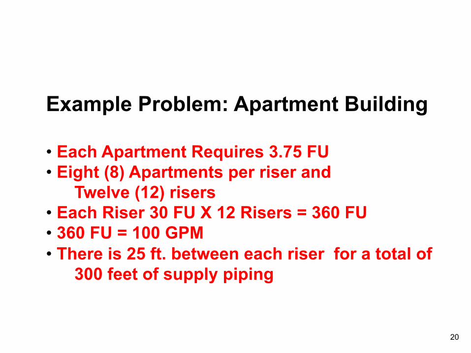
Example Problem: Apartment Building • Each Apartment Requires 3.75 FU • Eight (8) Apartments per riser and Twelve (12) risers • Each Riser 30 FU X 12 Risers = 360 FU • 360 FU = 100 GPM • There is 25 ft. between each riser for a total of 300 feet of supply piping
20

12 11 10 9 8 7 6 5 4 3 2 1 30 60 90 120 150 180 210 240 270 300 330 360
Simple Recirculation System
Riser # F.U.
Count
Check Valve CW
“A”
Heater
“B” 1 1/4” 1 1/2” 2” 2 1/2” 2”
2 1/2”
Recirculation Pump
Recirculation Return
Apartment Building Example (Supply pipe 300 feet long)
21
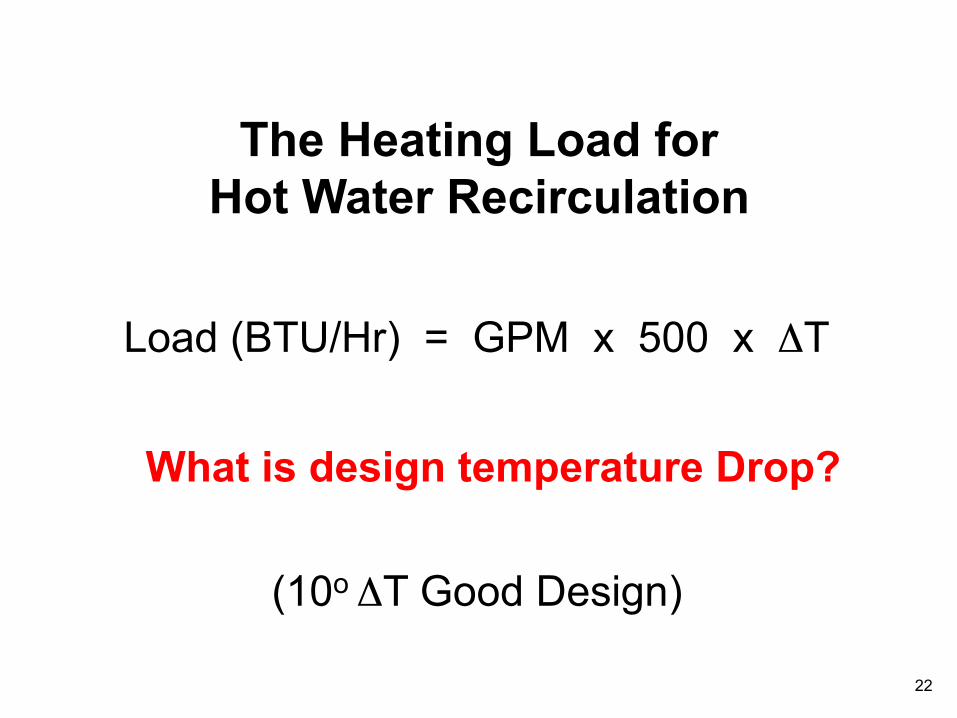
The Heating Load for Hot Water Recirculation
Load (BTU/Hr) = GPM x 500 x ΔT
What is design temperature Drop?
(10o ΔT Good Design)
22
E D
C
B A
Recirculated Main
Non-Recirculated Riser
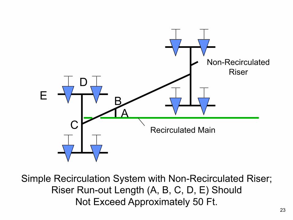
Simple Recirculation System with Non-Recirculated Riser; Riser Run-out Length (A, B, C, D, E) Should
Not Exceed Approximately 50 Ft. 23
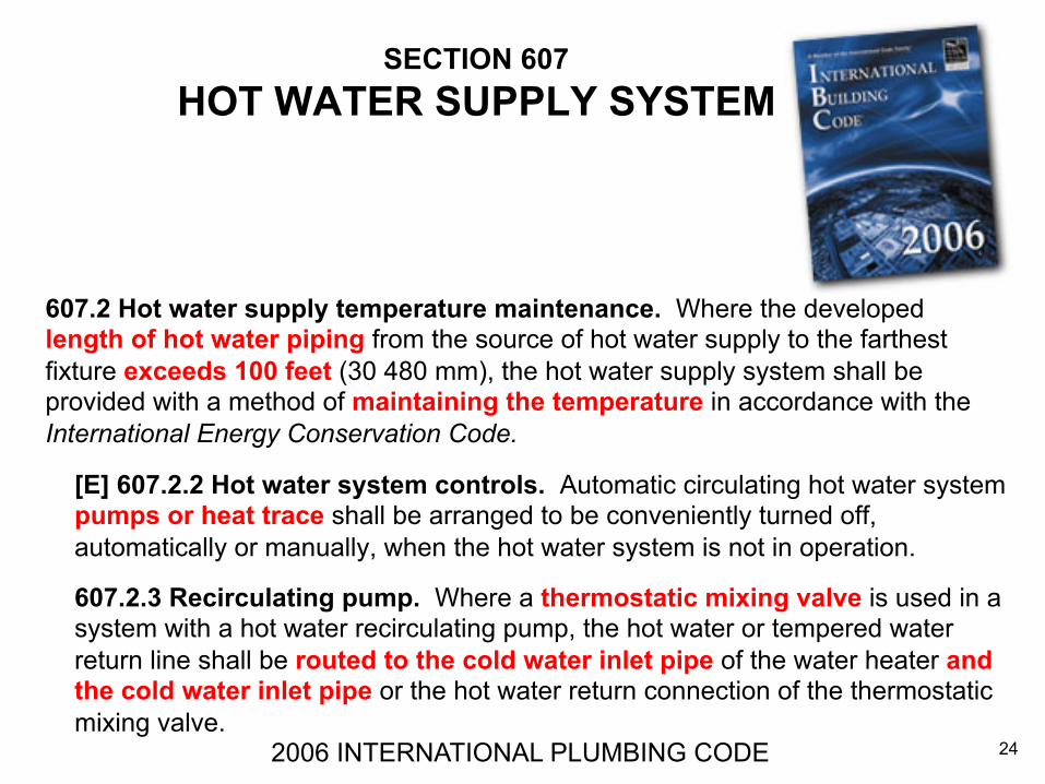
SECTION 607 HOT WATER SUPPLY SYSTEM
607.2 Hot water supply temperature maintenance. Where the developed length of hot water piping from the source of hot water supply to the farthest fixture exceeds 100 feet (30 480 mm), the hot water supply system shall be provided with a method of maintaining the temperature in accordance with the International Energy Conservation Code.
2006 INTERNATIONAL PLUMBING CODE
[E] 607.2.2 Hot water system controls. Automatic circulating hot water system pumps or heat trace shall be arranged to be conveniently turned off, automatically or manually, when the hot water system is not in operation.
607.2.3 Recirculating pump. Where a thermostatic mixing valve is used in a system with a hot water recirculating pump, the hot water or tempered water return line shall be routed to the cold water inlet pipe of the water heater and the cold water inlet pipe or the hot water return connection of the thermostatic mixing valve.
24
Water closets (toilets) - flushometer valve type
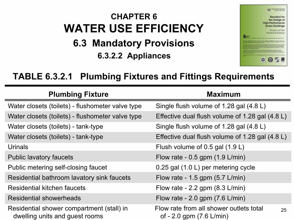
CHAPTER 6 WATER USE EFFICIENCY
TABLE 6.3.2.1 Plumbing Fixtures and Fittings Requirements
6.3.2.2 Appliances 6.3 Mandatory Provisions
Water closets (toilets) - flushometer valve type
Water closets (toilets) - tank-type Water closets (toilets) - tank-type Urinals Public lavatory faucets Public metering self-closing faucet Residential bathroom lavatory sink faucets Residential kitchen faucets Residential showerheads Residential shower compartment (stall) in dwelling units and guest rooms
Single flush volume of 1.28 gal (4.8 L) Effective dual flush volume of 1.28 gal (4.8 L) Single flush volume of 1.28 gal (4.8 L) Effective dual flush volume of 1.28 gal (4.8 L) Flush volume of 0.5 gal (1.9 L) Flow rate - 0.5 gpm (1.9 L/min) 0.25 gal (1.0 L) per metering cycle Flow rate - 1.5 gpm (5.7 L/min) Flow rate - 2.2 gpm (8.3 L/min) Flow rate - 2.0 gpm (7.6 L/min) Flow rate from all shower outlets total of - 2.0 gpm (7.6 L/min)
Plumbing Fixture Maximum
25
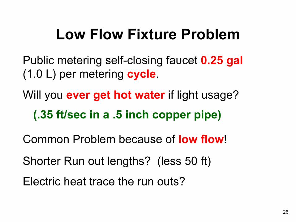
Low Flow Fixture Problem Public metering self-closing faucet 0.25 gal (1.0 L) per metering cycle.
Will you ever get hot water if light usage?
(.35 ft/sec in a .5 inch copper pipe)
Common Problem because of low flow!
Shorter Run out lengths? (less 50 ft)
Electric heat trace the run outs?
26
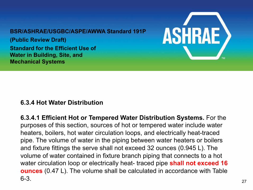
6.3.4 Hot Water Distribution 6.3.4.1 Efficient Hot or Tempered Water Distribution Systems. For the purposes of this section, sources of hot or tempered water include water heaters, boilers, hot water circulation loops, and electrically heat-traced pipe. The volume of water in the piping between water heaters or boilers and fixture fittings the serve shall not exceed 32 ounces (0.945 L). The volume of water contained in fixture branch piping that connects to a hot water circulation loop or electrically heat- traced pipe shall not exceed 16 ounces (0.47 L). The volume shall be calculated in accordance with Table 6-3.
BSR/ASHRAE/USGBC/ASPE/AWWA Standard 191P (Public Review Draft) Standard for the Efficient Use of Water in Building, Site, and Mechanical Systems
27

12 11 10 9 8 7 6 5 4 3 2 1 30 60 90 120 150 180 210 240 270 300 330 360
Simple Recirculation System
Riser # F.U.
Count
Check Valve CW
“A”
Heater
“B” 1 1/4” 1 1/2” 2” 2 1/2” 2”
2 1/2”
Recirculation Pump
Recirculation Return
What is heat loss of supply pipe?
28
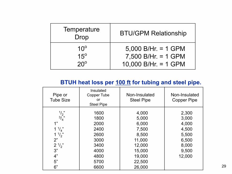
Temperature Drop
10o
15o
20o
BTU/GPM Relationship
5,000 B/Hr. = 1 GPM 7,500 B/Hr. = 1 GPM 10,000 B/Hr. = 1 GPM
1/2” 3/4” 1” 1 1/4” 1 1/2” 2” 2 1/2” 3” 4” 5” 6”
1600 1800 2000 2400 2600 3000 3400 4000 4800 5700 6600
4,000 5,000 6,000 7,500 8,500 11,000 12,000 15,000 19,000 22,500 26,000
2,300 3,000 4,000 4,500 5,500 6,500 8,000 9,500 12,000
Pipe or Tube Size
Insulated Copper Tube
or Steel Pipe
Non-Insulated Steel Pipe
Non-Insulated Copper Pipe
BTUH heat loss per 100 ft for tubing and steel pipe.
29

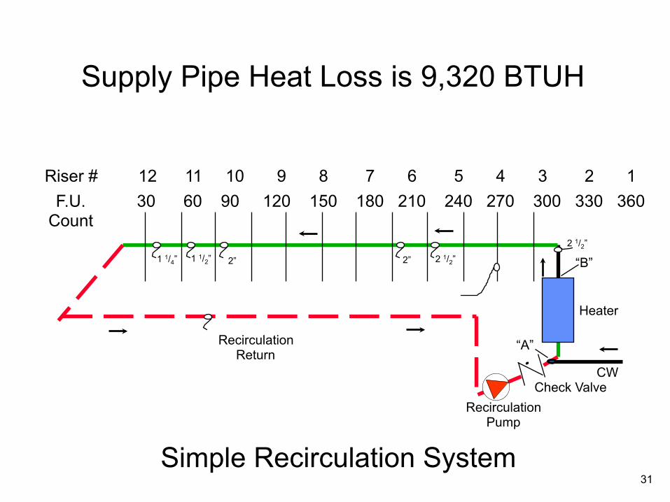
Using insulated copper tube, 25 ft. length between riser take-off points, supply line heat loss to the farthest riser take-off is as follows: Heat loss, BTUH B - #1 2-1/2” 30 ft. 3400/100 3400 x 30/100 = 1020 #1 - #4 2-1/2” 75 ft. 3400/100 3400 x 75/100 = 2550 #4 - #10 2” 150 ft. 3000/100 3000 x 150/100 = 4500 #10 - #11 1-1/2” 25 ft 2600/100 2600 x 25/100 = 650 #11 - #12 1-1/4” 25 ft 2400/100 2400 x 25/100 = 600 TOTAL SUPPLY LINE HEAT LOSS = 9320 BTUH
30
12 11 10 9 8 7 6 5 4 3 2 1 30 60 90 120 150 180 210 240 270 300 330 360
Simple Recirculation System
Riser # F.U.
Count
Check Valve CW
“A”
Heater
“B” 1 1/4” 1 1/2” 2” 2 1/2” 2”
2 1/2”
Recirculation Pump
Recirculation Return
Supply Pipe Heat Loss is 9,320 BTUH
31
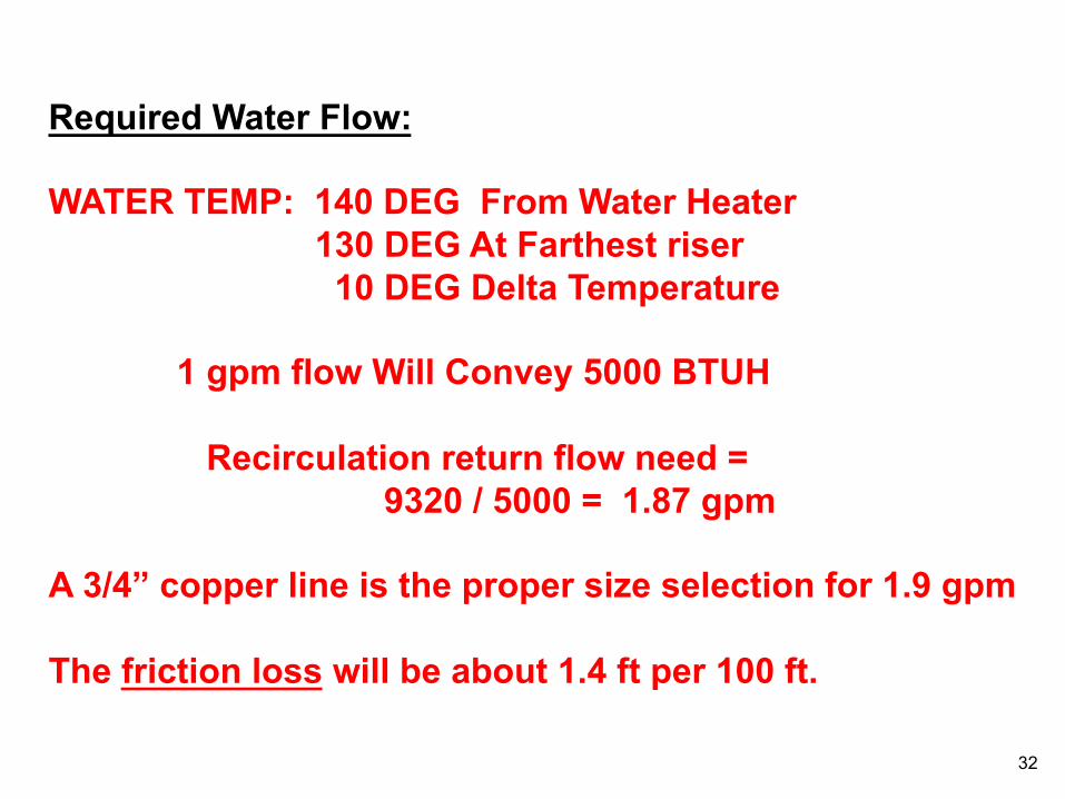
Required Water Flow: WATER TEMP: 140 DEG From Water Heater 130 DEG At Farthest riser 10 DEG Delta Temperature 1 gpm flow Will Convey 5000 BTUH Recirculation return flow need = 9320 / 5000 = 1.87 gpm A 3/4” copper line is the proper size selection for 1.9 gpm The friction loss will be about 1.4 ft per 100 ft.
32
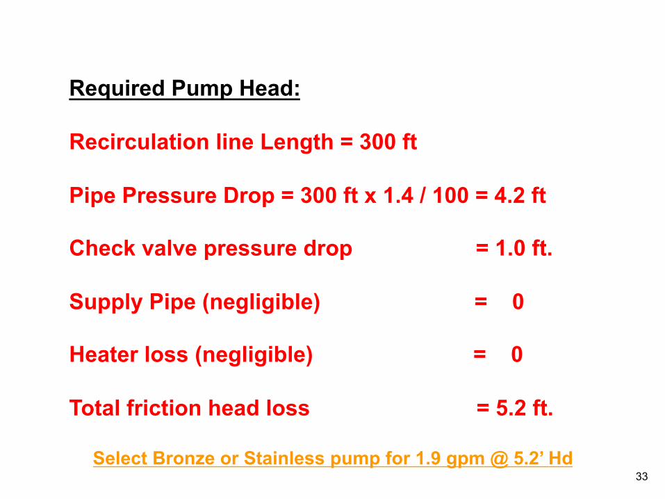
Required Pump Head: Recirculation line Length = 300 ft Pipe Pressure Drop = 300 ft x 1.4 / 100 = 4.2 ft Check valve pressure drop = 1.0 ft. Supply Pipe (negligible) = 0 Heater loss (negligible) = 0 Total friction head loss = 5.2 ft.
Select Bronze or Stainless pump for 1.9 gpm @ 5.2’ Hd 33
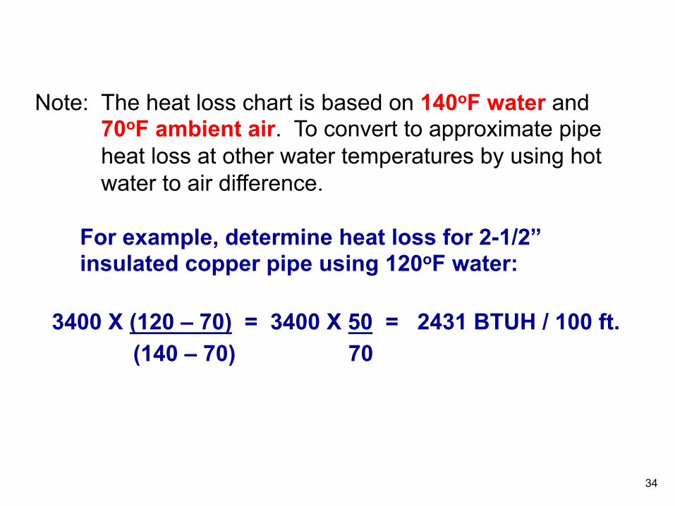
3400 X (120 – 70) = 3400 X 50 = 2431 BTUH / 100 ft. (140 – 70) 70
The heat loss chart is based on 140oF water and 70oF ambient air. To convert to approximate pipe heat loss at other water temperatures by using hot water to air difference.
Note:
For example, determine heat loss for 2-1/2” insulated copper pipe using 120oF water:
34
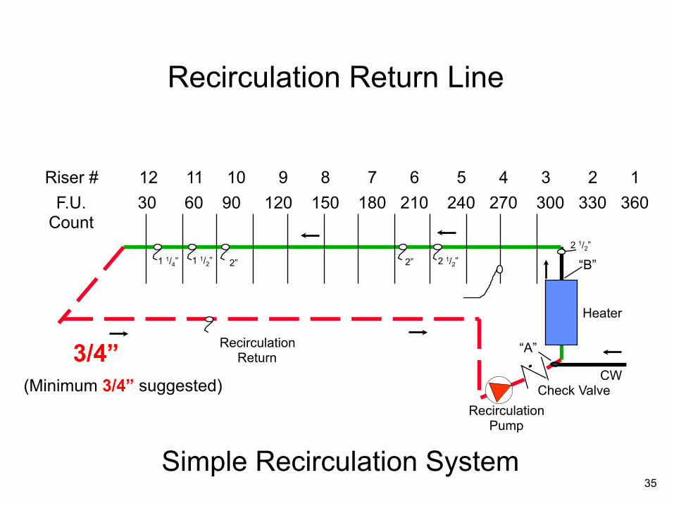
12 11 10 9 8 7 6 5 4 3 2 1 30 60 90 120 150 180 210 240 270 300 330 360
Simple Recirculation System
Riser # F.U.
Count
Check Valve CW
“A”
Heater
“B” 1 1/4” 1 1/2” 2” 2 1/2” 2”
2 1/2”
Recirculation Pump
Recirculation Return 3/4”
Recirculation Return Line
(Minimum 3/4” suggested)
35
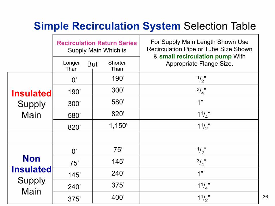
Insulated Supply Main
Non Insulated
Supply Main
0’
190’
300’
580’
820’
0’
75’
145’
240’
375’
190’
300’
580’
820’
1,150’
75’
145’
240’
375’
400’
1/2”
3/4”
1”
11/4”
11/2”
1/2”
3/4”
1”
11/4”
11/2”
Recirculation Return Series Supply Main Which is
Longer Than
Shorter Than
For Supply Main Length Shown Use Recirculation Pipe or Tube Size Shown
& small recirculation pump With Appropriate Flange Size. But
Simple Recirculation System Selection Table
36

Recirculating With No Return Line
No Return Line Required!
37
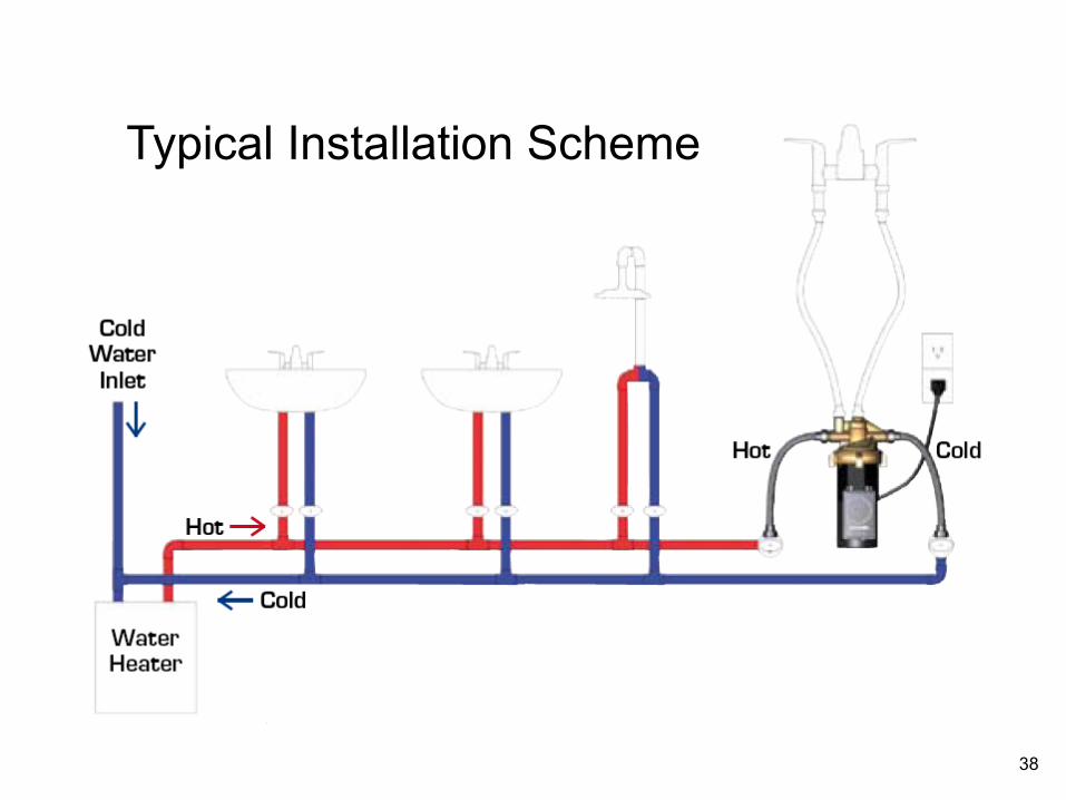
Typical Installation Scheme
38

Typical Installation “Tankless Water Heater”
ecocirc B 23-5 ACT (up to 23 ft pump head)
Installed at furthest fixture from the water
heater 39

40
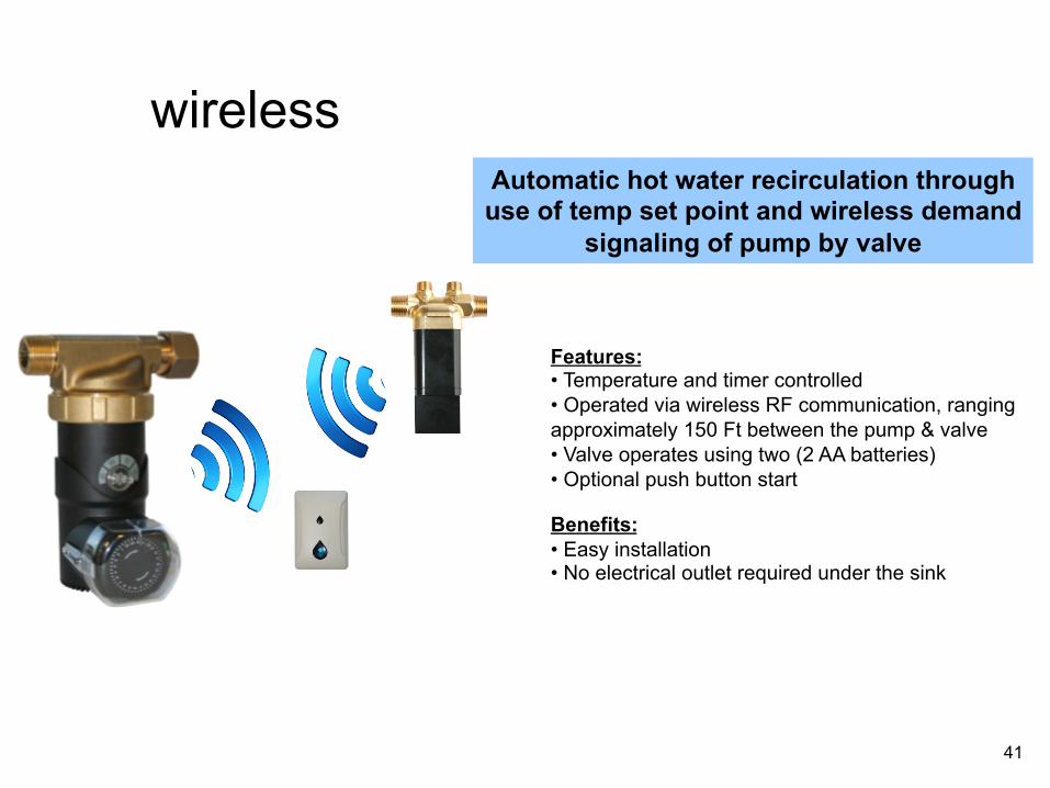
Automatic hot water recirculation through use of temp set point and wireless demand
signaling of pump by valve
Features: • Temperature and timer controlled • Operated via wireless RF communication, ranging approximately 150 Ft between the pump & valve • Valve operates using two (2 AA batteries) • Optional push button start
Benefits: • Easy installation • No electrical outlet required under the sink
wireless
41
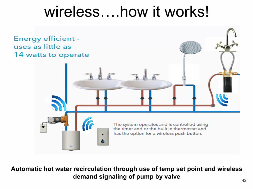
wireless….how it works!
Automatic hot water recirculation through use of temp set point and wireless
demand signaling of pump by valve 42
Watch out for water heater temperature control
Nothing Beats Storage 43

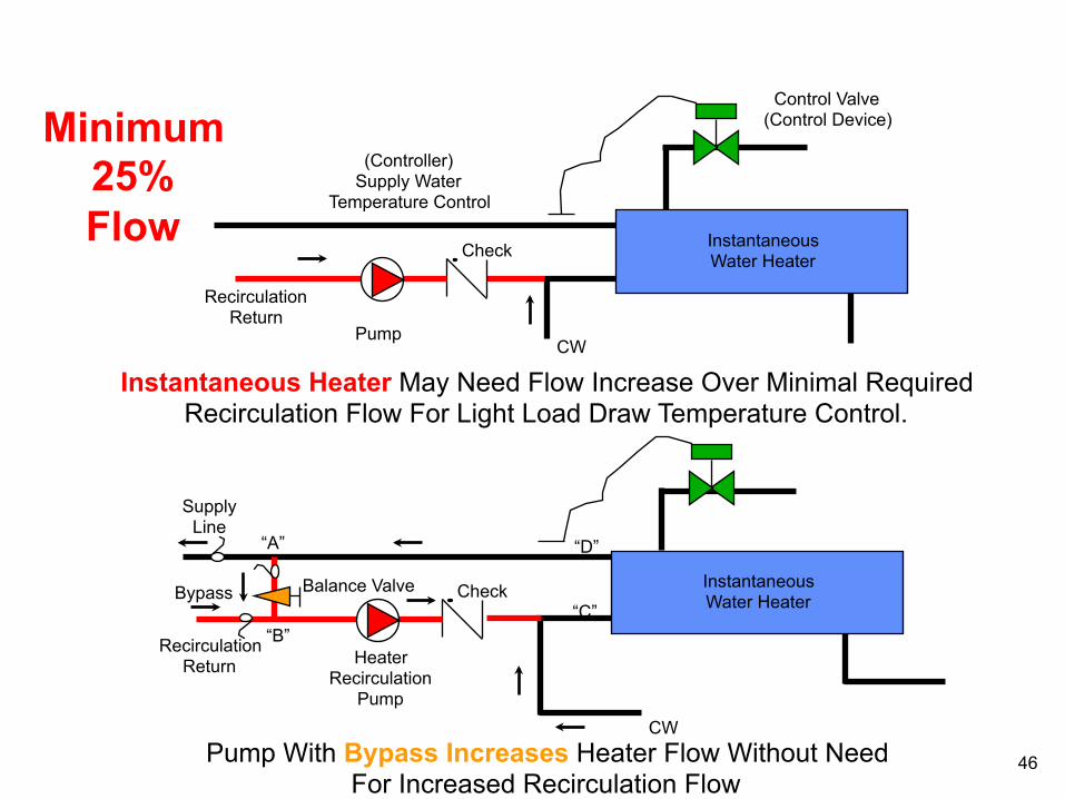
An increase in instantaneous heater flow rate during the light load draw will increase light load temperature control stability. This is because with a high flow rate, the controller needs only to measure temperature change to establish the load set point for the control device.
Instantaneous heater flow rate during periods of light load draw should be increased to about 25 percent of the expected Hunter flow rate.
Domestic hot water recirculation: I
By: Gil Carson, Director, Technical Services, ITT Fluid Handling Div., Skokie, Ill.
Reprinted from the October 1985 issue of HEATING/PIPING/AIR CONDITIONING. Copyright 1985 by Penton Publishing, a division of Pittway Corp.
44
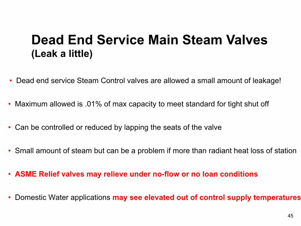
Dead End Service Main Steam Valves (Leak a little)
• Dead end service Steam Control valves are allowed a small amount of leakage!
• Maximum allowed is .01% of max capacity to meet standard for tight shut off
• Can be controlled or reduced by lapping the seats of the valve
• Small amount of steam but can be a problem if more than radiant heat loss of station
• ASME Relief valves may relieve under no-flow or no loan conditions
• Domestic Water applications may see elevated out of control supply temperatures
45
Control Valve (Control Device)
(Controller) Supply Water
Temperature Control
Recirculation Return
Pump
Check
CW
Instantaneous Water Heater
Instantaneous Heater May Need Flow Increase Over Minimal Required Recirculation Flow For Light Load Draw Temperature Control.
Balance Valve
Recirculation Return Heater
Recirculation Pump
Check
CW
Instantaneous Water Heater “C”
“B”
Bypass
“D” “A”
Supply Line
Pump With Bypass Increases Heater Flow Without Need For Increased Recirculation Flow
Minimum 25% Flow
46
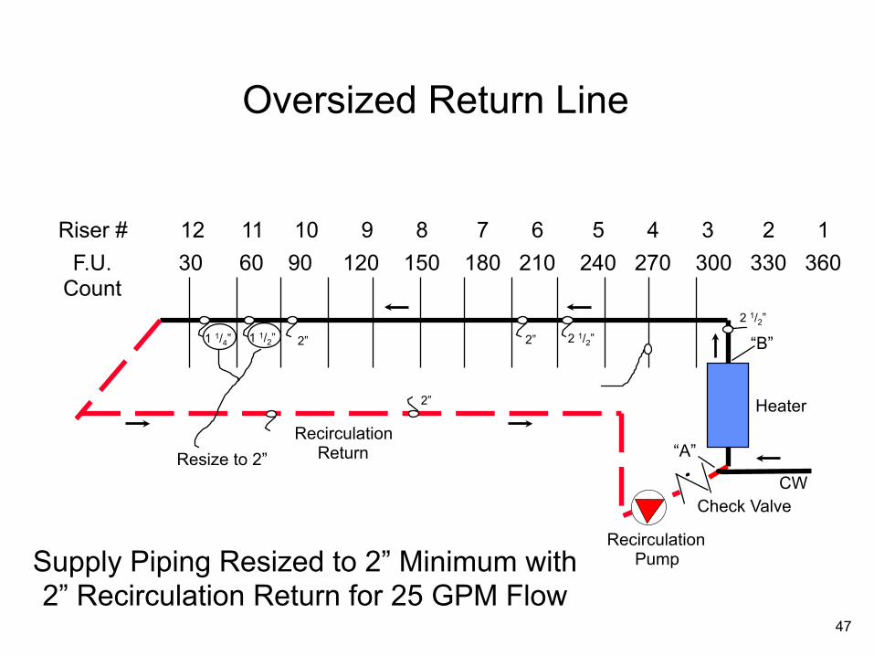
12 11 10 9 8 7 6 5 4 3 2 1 30 60 90 120 150 180 210 240 270 300 330 360
Riser # F.U.
Count
Check Valve CW
“A”
Heater
“B” 1 1/4” 1 1/2” 2” 2 1/2” 2”
2 1/2”
Recirculation Pump
Recirculation Return Resize to 2”
2”
Supply Piping Resized to 2” Minimum with 2” Recirculation Return for 25 GPM Flow
Oversized Return Line
47

12 11 10 9 8 7 6 5 4 3 2 1 30 60 90 120 150 180 210 240 270 300 330 360
Riser # F.U.
Count
Check Valve CW
“B” Instantaneous
HW Heater
11/4” 11/2” 2” 2 1/2” 2”
2 1/2”
Recirculation Pump
Recirculation Return
Supply Piping Resized to 2” Minimum with
2” Recirculation Return for 25 GPM Flow
3/4” 2 ”
2 ” Balance Valve
“A”
Bypass Line in Equipment Room
48

Watch out for unbalanced riser flows
You must balance
Lead Free Balance Valve 49

Multi-Circuited Recirculation Main Example
Recirculation Pump
12 11 10 9 8 7 6 5 4 3 2 1 30 60 90 120 150 180 210 240 270 300 330 360
Riser # F.U.
Count
Check Valve
CW
“A”
Heater
1 1/4” 1 1/2” 2” 2 1/2” 2”
Low Rise Recirculation Return Balance Valve
“F”
71.75
1 1/2”
Balance Valve
Hi-Rise Recirculation
Return
82
92.25
102.5
112.75
123
133.25
143.5
1” 2”
2”
“B” 2”
(143.5 F.U.)
2 1/2” (503 F.U.)
“E”
“C” “D” 61.5
51.25
41
30.75
20.5
10.25
40’ F. U. Count
F. U. Count
Lead Free Balance Valve or Flow Limiter
2 1/2”
2” 1”
1 1/2”
1 1/4”
1 1/4”
1”
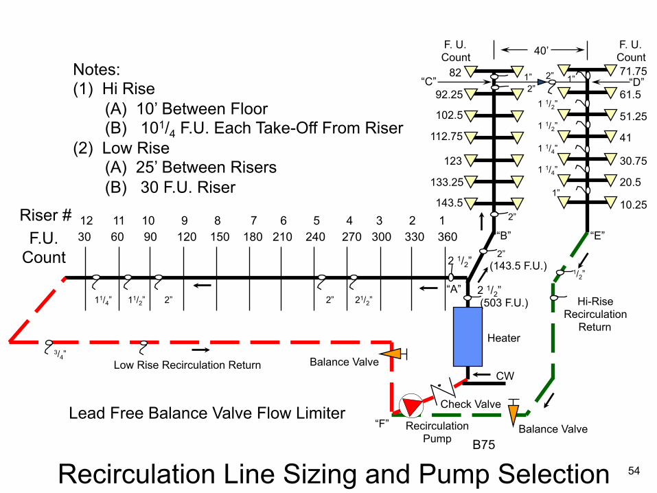
Notes: (1) Hi Rise (A) 10’ Between Floor (B) 101/4 F.U. Each Take-Off From Riser (2) Low Rise (A) 25’ Between Risers (B) 30 F.U. Riser
50
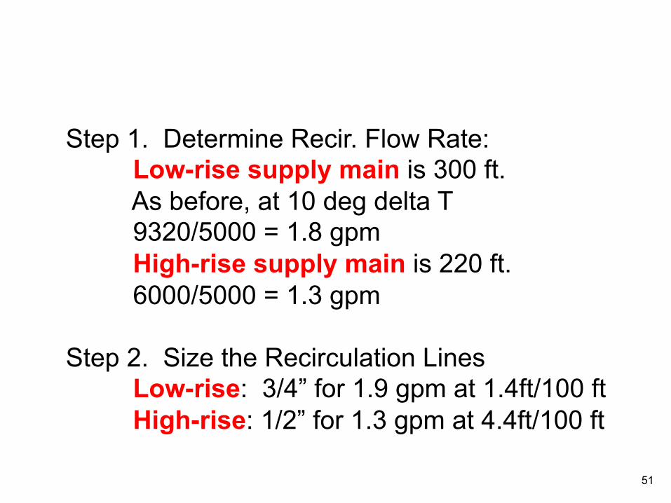
Step 1. Determine Recir. Flow Rate: Low-rise supply main is 300 ft. As before, at 10 deg delta T 9320/5000 = 1.8 gpm High-rise supply main is 220 ft. 6000/5000 = 1.3 gpm
Step 2. Size the Recirculation Lines
Low-rise: 3/4” for 1.9 gpm at 1.4ft/100 ft High-rise: 1/2” for 1.3 gpm at 4.4ft/100 ft
51
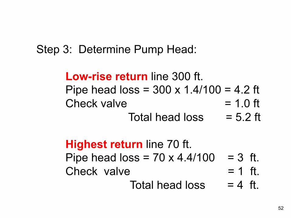
Step 3: Determine Pump Head:
Low-rise return line 300 ft. Pipe head loss = 300 x 1.4/100 = 4.2 ft Check valve = 1.0 ft Total head loss = 5.2 ft
Highest return line 70 ft. Pipe head loss = 70 x 4.4/100 = 3 ft. Check valve = 1 ft. Total head loss = 4 ft.
52
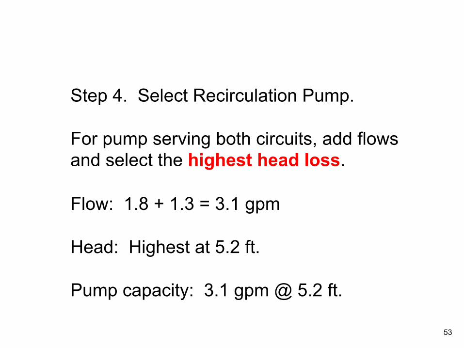
Step 4. Select Recirculation Pump. For pump serving both circuits, add flows and select the highest head loss. Flow: 1.8 + 1.3 = 3.1 gpm Head: Highest at 5.2 ft. Pump capacity: 3.1 gpm @ 5.2 ft.
53
Recirculation Line Sizing and Pump Selection
Recirculation Pump
12 11 10 9 8 7 6 5 4 3 2 1 30 60 90 120 150 180 210 240 270 300 330 360
Riser # F.U.
Count
Check Valve
CW
“A”
Heater
11/4” 11/2” 2” 21/2” 2”
Low Rise Recirculation Return Balance Valve
“F”
71.75
1 1/2”
Balance Valve
Hi-Rise Recirculation
Return
82
92.25
102.5
112.75
123
133.25
143.5
1” 2”
2”
“B” 2”
(143.5 F.U.)
2 1/2” (503 F.U.)
“E”
“C” “D” 61.5
51.25
41
30.75
20.5
10.25
40’ F. U. Count
F. U. Count
Lead Free Balance Valve Flow Limiter
2 1/2”
2” 1”
1 1/2”
1 1/4”
1 1/4”
1”
Notes: (1) Hi Rise (A) 10’ Between Floor (B) 101/4 F.U. Each Take-Off From Riser (2) Low Rise (A) 25’ Between Risers (B) 30 F.U. Riser
3/4”
B75
1/2”
54

Even though the return line is 70 ft, the supply line is 220 ft. Based on head loss a 1/2” return line was selected. However, since the supply line is 220 ft, we recommend a 3/4” return line be used.
55

Recirculation Line Sizing and Pump Selection
Recirculation Pump
12 11 10 9 8 7 6 5 4 3 2 1 30 60 90 120 150 180 210 240 270 300 330 360
Riser # F.U.
Count
Check Valve
CW
“A”
Heater
11/4” 11/2” 2” 21/2” 2”
Low Rise Recirculation Return Balance Valve
“F”
71.75
1 1/2”
Hi-Rise Recirculation
Return
82
92.25
102.5
112.75
123
133.25
143.5
1” 2”
2”
“B” 2”
(143.5 F.U.)
2 1/2” (503 F.U.)
“E”
“C” “D” 61.5
51.25
41
30.75
20.5
10.25
40’ F. U. Count
F. U. Count
2 1/2”
2” 1”
1 1/2”
1 1/4”
1 1/4”
1”
Notes: (1) Hi Rise (A) 10’ Between Floor (B) 101/4 F.U. Each Take-Off From Riser (2) Low Rise (A) 25’ Between Risers (B) 30 F.U. Riser
3/4”
1/2” use 3/4”
Lead Free Balance Valve or Flow Limiter
56
Balance Valve

Two observations: 1. Many of the recirculation problems we have seen are on multi-circuited recirculation systems. A main HW loop and loops to remote showers or lavatories. These must be balanced if hot water is to ever get to these fixtures. 2. Do not use a 1/2” return line on any system of any size. A minimum 3/4” return line size will eliminate many problems.
57

Watch out for unbalanced riser flows
You must balance
Lead Free Balance Valve 58

8 Story Hotel
Worlds Fair
Alcoa, TN
(No Balance Valves) Startup Problems
Which is the Free Hotel Room?
59
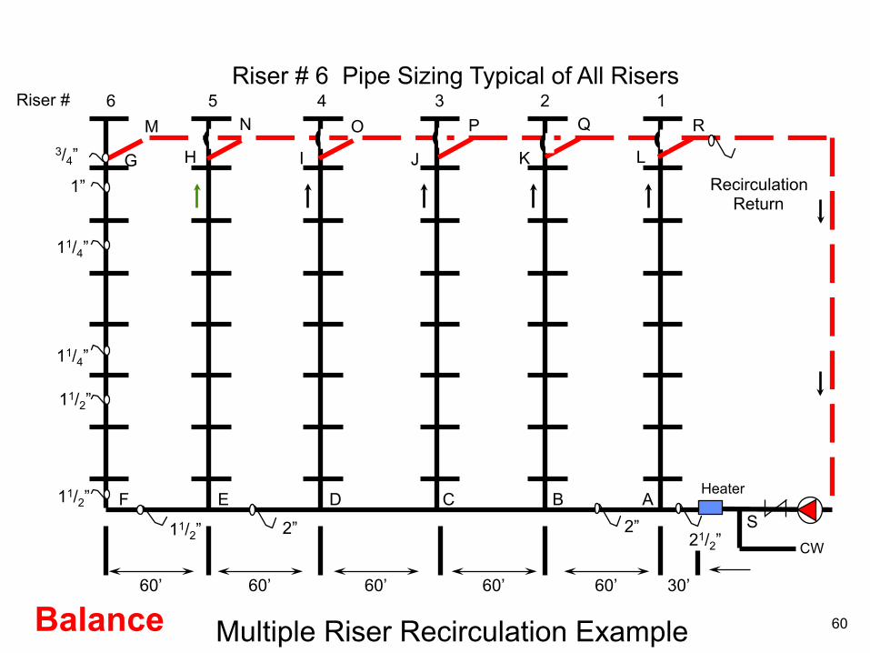
60’ 60’ 60’ 60’ 60’ 30’
3/4”
1”
11/4”
11/4”
11/2”
11/2”
11/2” 2”
6 5 4 3 2 1 M N O P Q R
G H I J K L
Riser #
CW
Heater
S F E D C B A
2” 21/2”
Multiple Riser Recirculation Example Balance
Riser # 6 Pipe Sizing Typical of All Risers
Recirculation Return
60

60’ 60’ 60’ 60’ 60’ 30’
3/4”
1”
11/4”
11/4”
11/2”
11/2”
11/2” 2”
6 5 4 3 2 1 M N O P Q R
G H I J K L
Riser #
CW
Heater
S F E D C B A
2” 21/2”
Multiple Riser Recirculation Example Balance
Riser # 6 Pipe Sizing Typical of All Risers
Recirculation Return
Lead Free Balance Valve
61
62
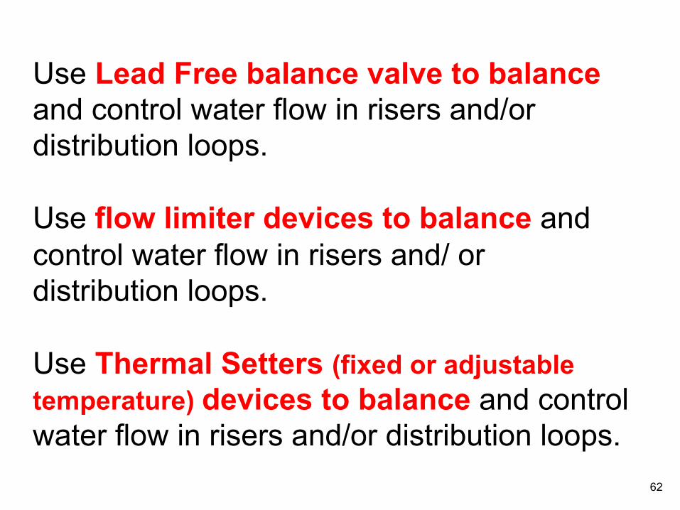
Use Lead Free balance valve to balance and control water flow in risers and/or distribution loops. Use flow limiter devices to balance and control water flow in risers and/ or distribution loops. Use Thermal Setters (fixed or adjustable temperature) devices to balance and control water flow in risers and/or distribution loops.
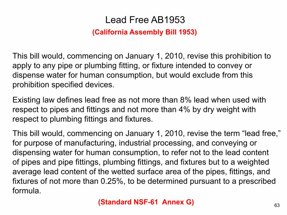
This bill would, commencing on January 1, 2010, revise this prohibition to apply to any pipe or plumbing fitting, or fixture intended to convey or dispense water for human consumption, but would exclude from this prohibition specified devices.
Existing law defines lead free as not more than 8% lead when used with respect to pipes and fittings and not more than 4% by dry weight with respect to plumbing fittings and fixtures.
This bill would, commencing on January 1, 2010, revise the term “lead free,” for purpose of manufacturing, industrial processing, and conveying or dispensing water for human consumption, to refer not to the lead content of pipes and pipe fittings, plumbing fittings, and fixtures but to a weighted average lead content of the wetted surface area of the pipes, fittings, and fixtures of not more than 0.25%, to be determined pursuant to a prescribed formula.
Lead Free AB1953 (California Assembly Bill 1953)
(Standard NSF-61 Annex G) 63
Ret
urn
Sup
ply
Sup
ply
Sup
ply
X X
Ret
urn
Sup
ply
Sup
ply
X
Return
Sup
ply
Sup
ply
Vent
Mai
n S
uppl
y
{ }
A B C
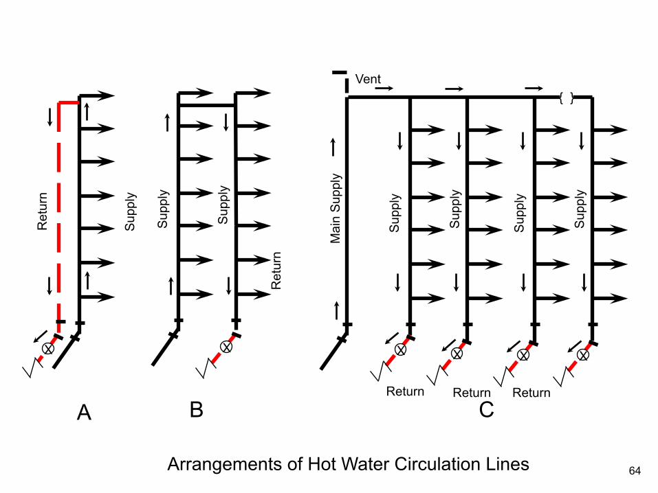
Arrangements of Hot Water Circulation Lines
X
Return
X
Return
X
64
Watch out for recirculation with reducing valves
Never recircuit across a pressure reducing valve
65

High Rise Hotel
Worlds Fair
Knoxville, TN
(Circulating across PRV) Startup Problems
Which is the Free Hotel Room?
66
118 120 121 120
Heater C. W.
# B 100
F G A
B
118
20
20
70
70
E H
No Flow
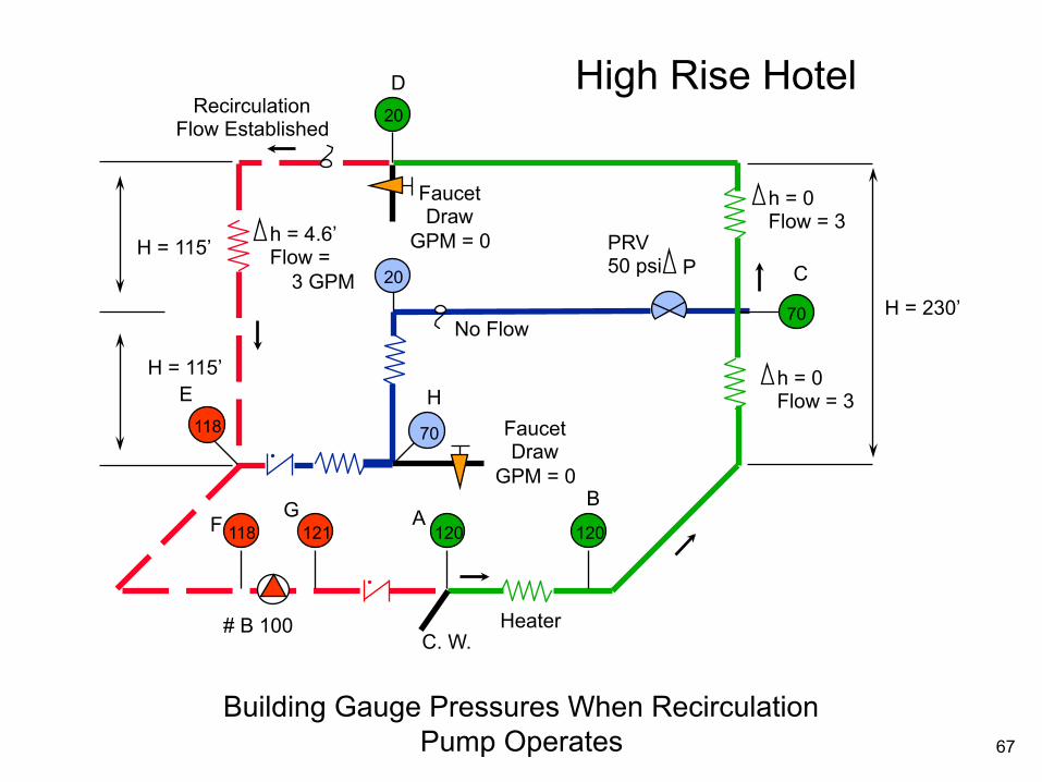
Building Gauge Pressures When Recirculation Pump Operates
Faucet Draw
GPM = 0
h = 0 Flow = 3
C
h = 0 Flow = 3
H = 230’
H = 115’
H = 115’
Recirculation Flow Established
Faucet Draw
GPM = 0 h = 4.6’ Flow =
3 GPM
D
PRV 50 psi P
High Rise Hotel
67

68 120 121 120
Heater C. W. Pump 122’ @ 6 GPM
F
G A B
68
20
20
70
69
E H
Larger Pump May or May Not Solve Recirculation Problem
Faucet Draw
GPM = 0
h = 0 Flow = 6
C
h = 0 Flow = 3
H = 230’
H = 115’
H = 115’
Faucet Draw
GPM = 0 h = 4.6’ Flow =
3 GPM
D
P.R. Valve
h = 2.3’ Flow = 3
Balance Valve 52 PSI
P @ 3 GPM
h = 2.3’ Flow = 3 GPM
High Rise Hotel
68
Heater
Shower
Shower
Shower Mix Valve
CW
CW
HW
CW PRV
HW PRV
CW
HW
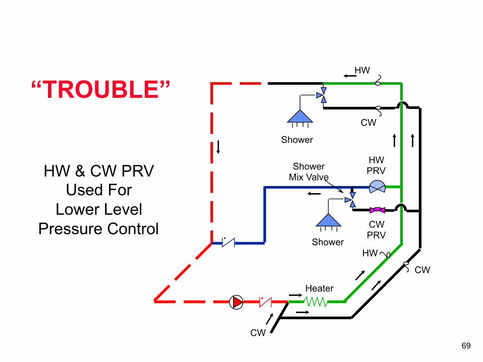
“TROUBLE”
HW & CW PRV Used For
Lower Level Pressure Control
69
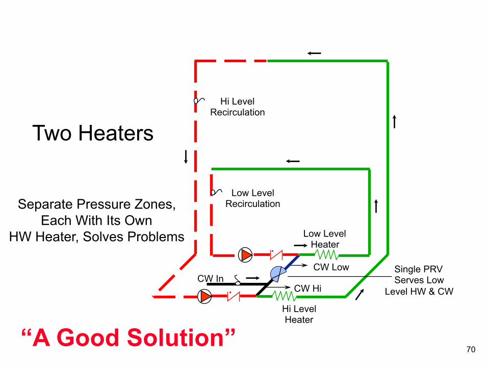
Hi Level Recirculation
Low Level Recirculation
Low Level Heater
CW Low
CW Hi
Hi Level Heater
Single PRV Serves Low
Level HW & CW CW In
Separate Pressure Zones, Each With Its Own
HW Heater, Solves Problems
Two Heaters
“A Good Solution” 70
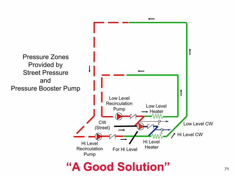
Low Level Recirculation
Pump Low Level Heater
Hi Level Heater
CW (Street)
Pressure Zones Provided by
Street Pressure and
Pressure Booster Pump
Low Level CW
Hi Level CW
Hi Level Recirculation
Pump For Hi Level
“A Good Solution” 71
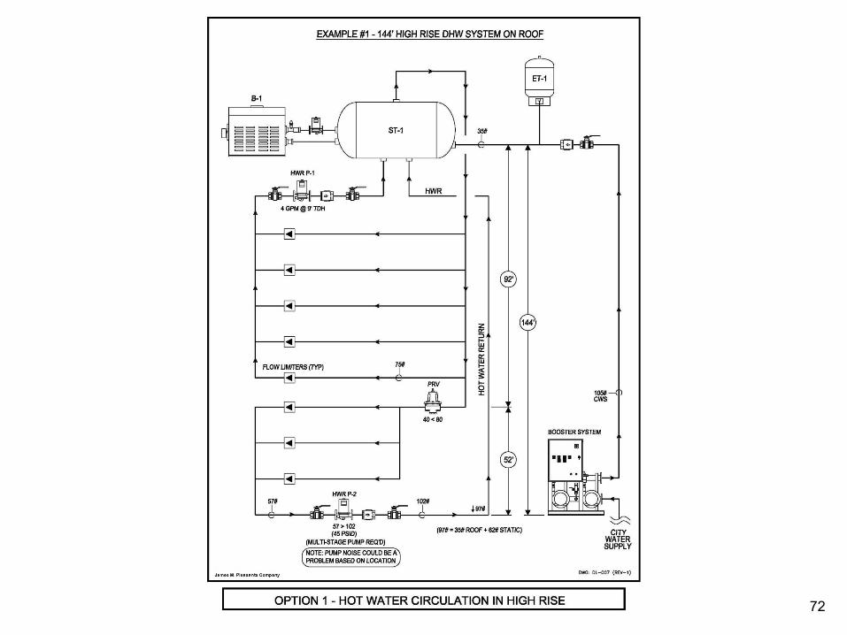
72
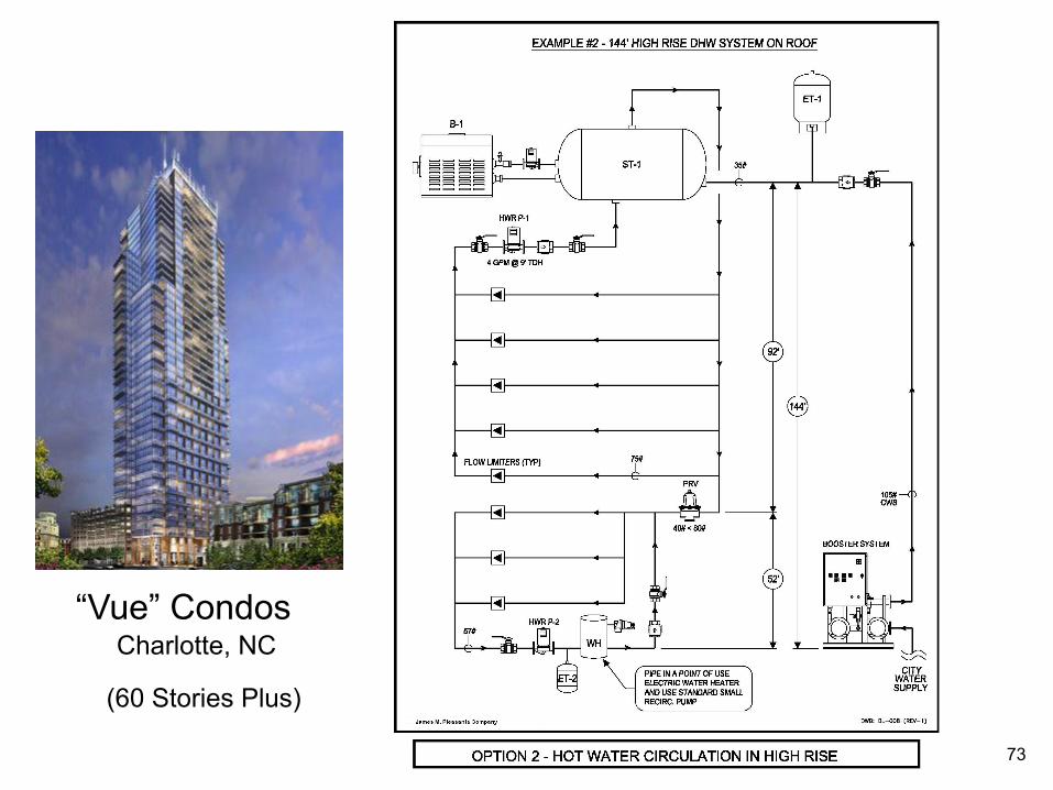
“Vue” Condos Charlotte, NC
(60 Stories Plus)
73

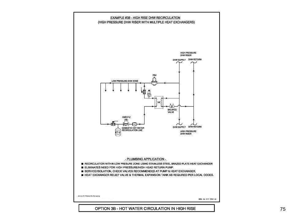
74
75

76
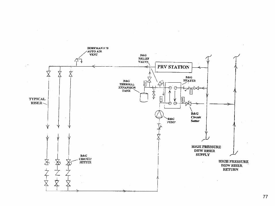
77
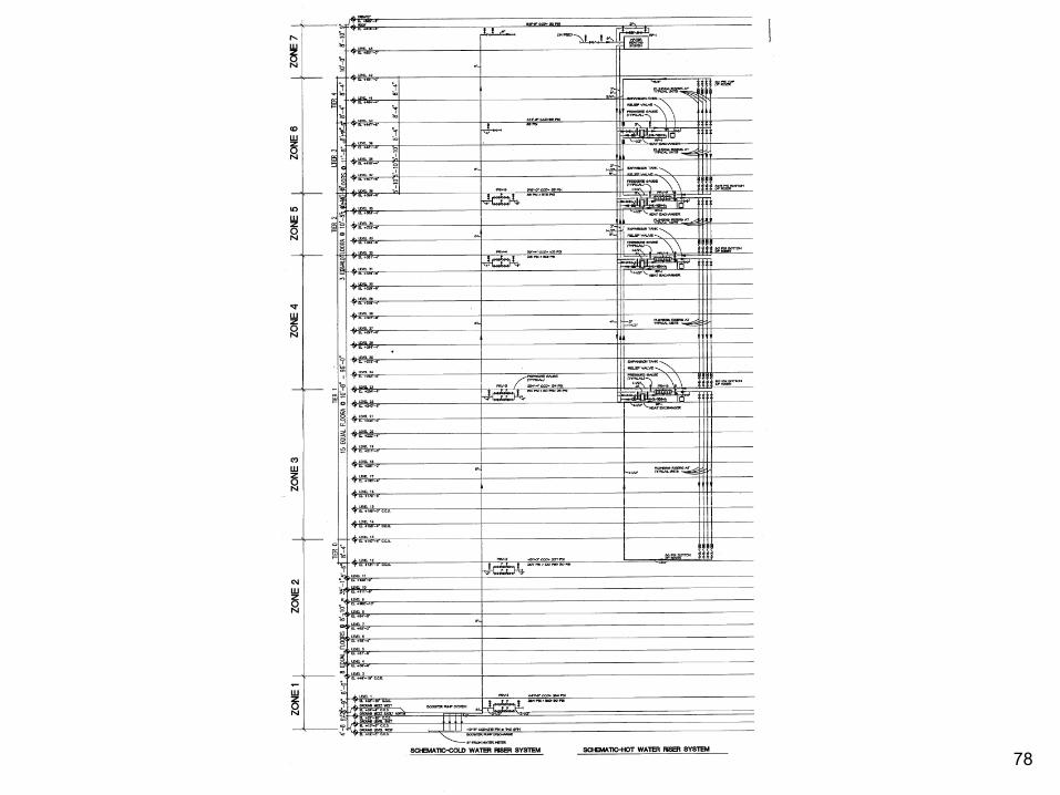
78

Single Temperature Recirculation System
Typical Installation
Storage Tank Water
Heater
Check Valve
Heat Trap 27” Drop
To Low Temperature Fixtures
Low Temperature Return Aquastat
Balancing Valve Recirculation
Pump
79

Dual Temperature Recirculation System
Typical Installation
Water Heater
Check Valve
Heat Trap 27” Drop
To Low Temperature Fixtures
Low Temperature Return Aquastat
Balancing Valve Recirculation
Pump Storage
Tank High Temperature Return
80
Storage Tank
Water Heater
Gas Fired Water Heater Detail
27” Min.
115o
130o
CWS
140o
110o
Expansion Tank
Dual Temperature Piping System
James M. Pleasants Company, Inc. 1-800-365-9010
Gas Cock
Balance Valve
Aqustat
Non-Condensing Water Heater 070709CE
81
Variable Speed Pressure Boosting
James M. Pleasants Company
www.jmpco.com
Approved by GBCI for 1 CE Hour
Course Approval Number is 0090007847
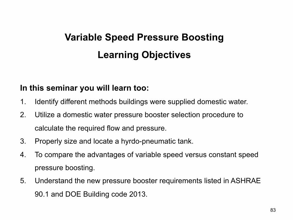
Variable Speed Pressure Boosting
Learning Objectives
In this seminar you will learn too: 1. Identify different methods buildings were supplied domestic water.
2. Utilize a domestic water pressure booster selection procedure to
calculate the required flow and pressure.
3. Properly size and locate a hyrdo-pneumatic tank.
4. To compare the advantages of variable speed versus constant speed
pressure boosting.
5. Understand the new pressure booster requirements listed in ASHRAE
90.1 and DOE Building code 2013.
83
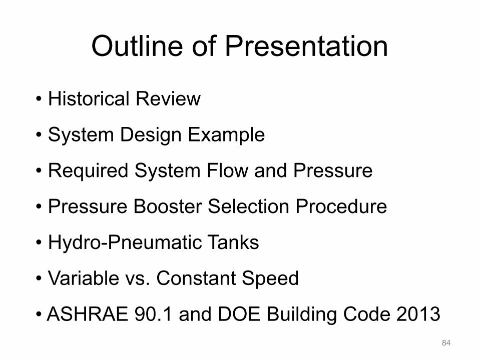
Outline of Presentation
84
• Historical Review
• System Design Example
• Required System Flow and Pressure
• Pressure Booster Selection Procedure
• Hydro-Pneumatic Tanks
• Variable vs. Constant Speed
• ASHRAE 90.1 and DOE Building Code 2013

Historical Review
85

1700 BC - Island of Crete-Minoan Palace had Terra Cotta hot and cold water supply piping and separate sewers constructed of stone.
52 AD - Romans had 220 miles of aqueducts to supply 300 gallons of water for every citizen.
79 AD - The Romans of Pompeii had water closets with a cistern to provide flush water and a separate sewer system. Lead and tile pipe was used for supply water. Public baths had hot water and were heated.
1596 - Sir John Harrington invented a water closet for Queen Elizabeth of England.
1775 - In England Alexander Cummings reinvented Harrington’s water closet.
1836 - In England Thomas Crapper is born. He was a plumber until 1904 and his company operated under the Crapper name until 1966.
1491 BC Approx. - Deuteronomy 23:12-14 (New International Version) (The First Latrine) 12 Designate a place outside the camp where you can go to relieve yourself. 13 As part of your equipment have something to dig with,…
1850 - privy - a room equipped with toilet (a private place)
Plumbing Water History Systems
86
700 BC Approx. - “Plumbum” - Latin for “Lead” - which is the origin of the word “Plumbing”.

87
Water covers more than
70% of the
earth’s surface.
about 97% is salty water
3% fresh water
World Population
1802 1 Billion 2000 6 Billion 2040 9.0 Billion
World Population
1802 1 Billion 2000 6 Billion 2040 9 Billion
88
100 Psi
10 Psi
1 Psi
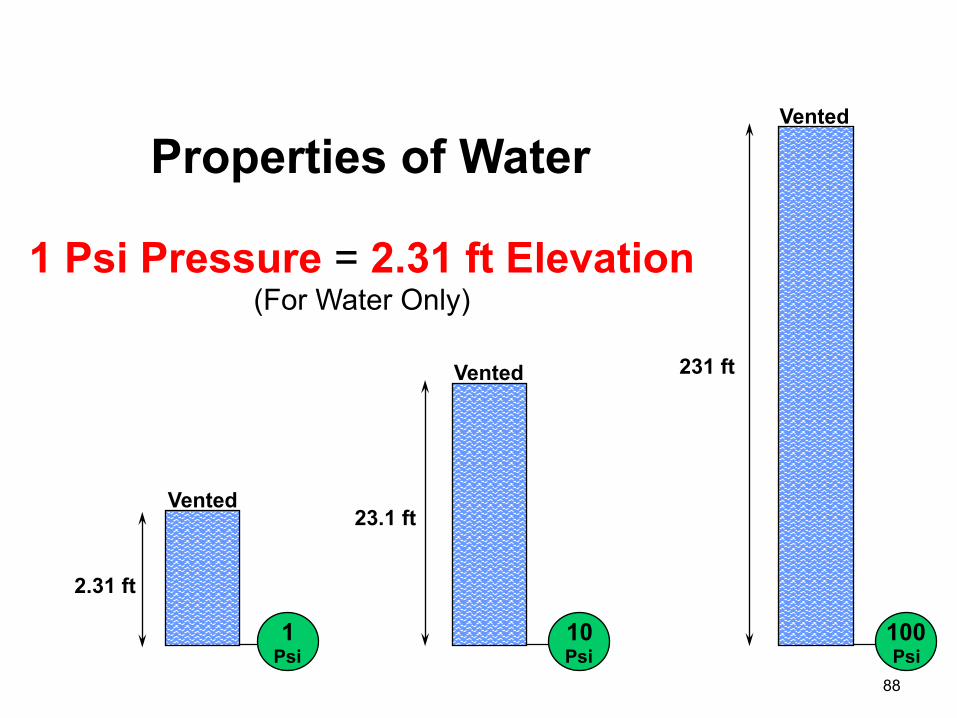
Properties of Water
Vented
Vented
Vented
2.31 ft
23.1 ft
231 ft
1 Psi Pressure = 2.31 ft Elevation (For Water Only)
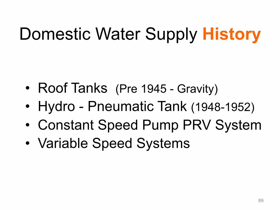
• Roof Tanks (Pre 1945 - Gravity)
• Hydro - Pneumatic Tank (1948-1952)
• Constant Speed Pump PRV System
• Variable Speed Systems
Domestic Water Supply History
89

Required Water Level
Tank
To System
Blow-Off Valve
Vent
Diaphragm Valve
Orifice/Needle Valve Pressure Reducing Valve
City Water Supply
By-Pass Valve
1829 Boston Tremont Hotel first with indoor plumbing with steam driven pump and roof tank.
Roof Tanks
90
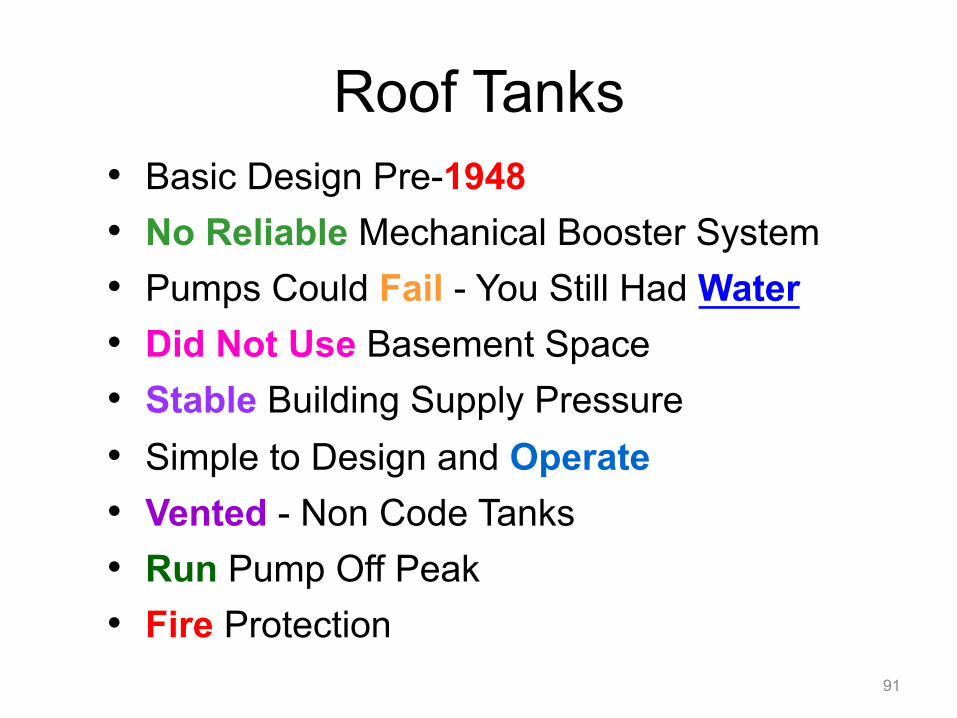
• Basic Design Pre-1948
• No Reliable Mechanical Booster System
• Pumps Could Fail - You Still Had Water
• Did Not Use Basement Space
• Stable Building Supply Pressure
• Simple to Design and Operate
• Vented - Non Code Tanks
• Run Pump Off Peak
• Fire Protection
Roof Tanks
91

High Water Level
Pressure Switch
Deep Well Pump
Solenoid Valve
Control for Hydro-Pneumatic Tanks Supplied by Deep Well Pumps
92

• Between 1952 and 1957
• Two 100% Pumps with Air Compressor
• Higher System Pressures
• Expensive Large Tanks Should be Code
• Expensive Floor Space Rooftop and Basement
• High Pneumatic Tank Maintenance
• Corrosion Problem Due to Oxygen
Hydro-Pneumatic Tanks
93
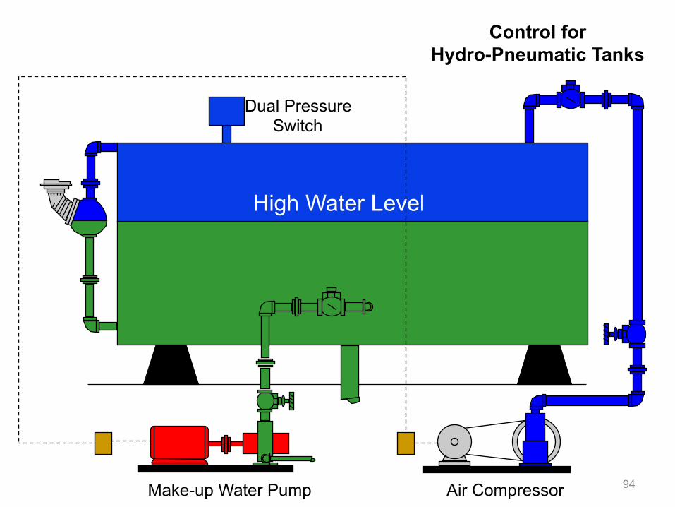
High Water Level
Dual Pressure Switch
Make-up Water Pump Air Compressor
Control for Hydro-Pneumatic Tanks
94
95
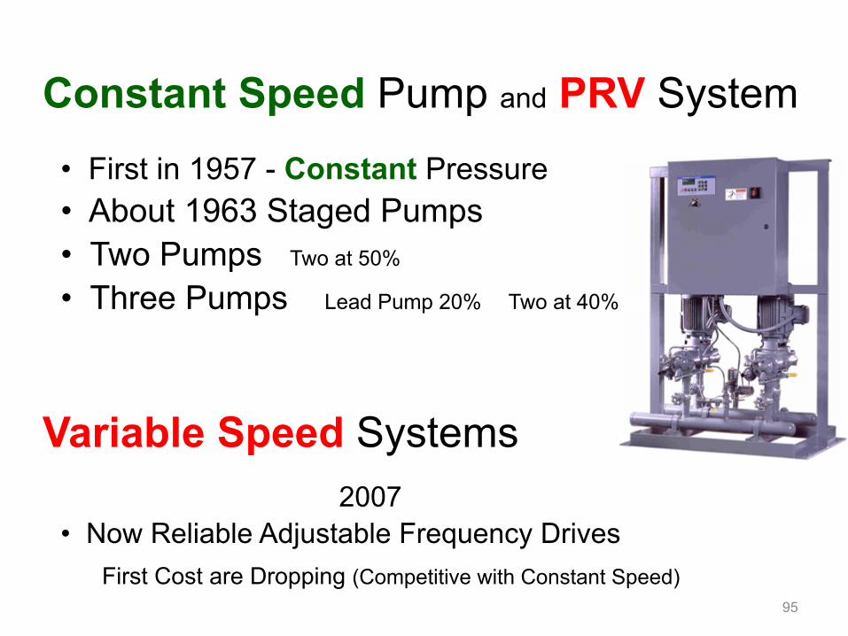
Constant Speed Pump and PRV System
• First in 1957 - Constant Pressure • About 1963 Staged Pumps • Two Pumps Two at 50% • Three Pumps Lead Pump 20% Two at 40%
Variable Speed Systems 2007
• Now Reliable Adjustable Frequency Drives First Cost are Dropping (Competitive with Constant Speed)

Introduction of
System Design Example
96

F.ixture U.nit and GPM
Example: Fixture unit counts determine your GPM flow rates.
100 Room Apartment Design
97

• Elevation of 116 ft to top • 10 Stories high - 10 apartments per floor • Each apartment has one bathroom group and kitchen sink
• City Pressure at Street Level Static 55 psi • Minimum City Water Pressure is 40 psi • Backflow Preventer and Water Meter Required • *Flush Tanks Used - Require 20 psi at the top
City Water 40 PSI Minimum Water
Meter
Backflow Preventer
Pressure Booster
10 Stories High
20 PSI (Minimum)
116 ft Elevation
Note: First few floors with street pressure?
*CAUTION: Specific Flow and Pressure Requirements will vary
100 Room Apartment
98
Critical Fixture

• Demand is based on Fixture Units (Check your local code on F.U.)
Domestic Water Supply GPM and Fixture Units
99
Tennessee Code Effective 3/1/07
IBC 2006 South Carolina Board of Building Codes Council Notice of Intention to Adopt Building Codes 2006 Edition of the International Plumbing Code
State Plumbing Codes
100
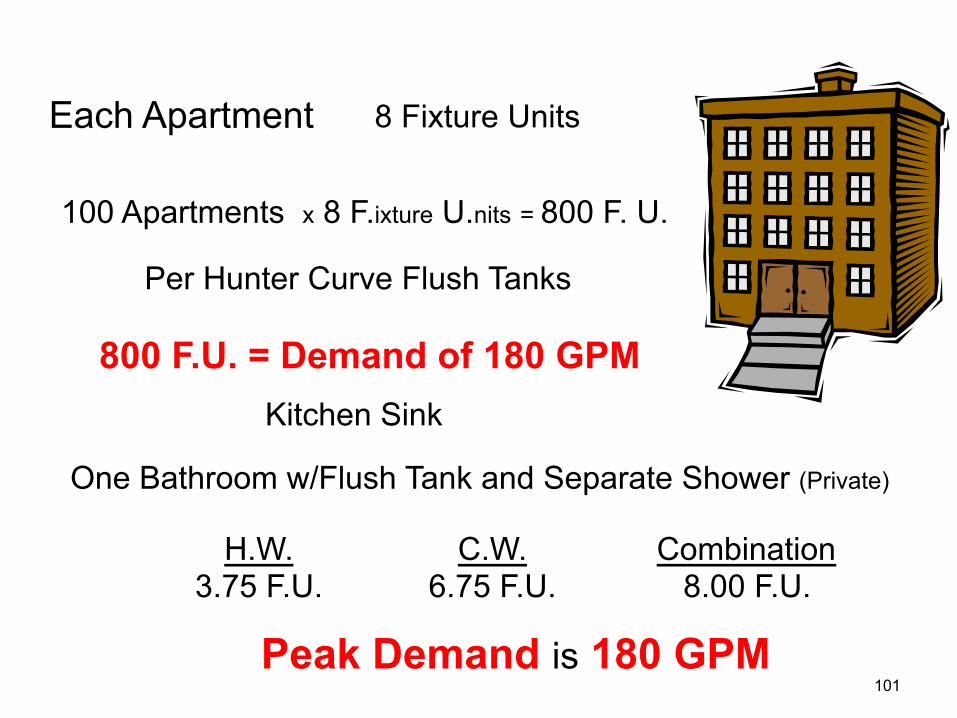
Each Apartment 8 Fixture Units
100 Apartments x 8 F.ixture U.nits = 800 F. U.
Per Hunter Curve Flush Tanks
800 F.U. = Demand of 180 GPM Kitchen Sink
One Bathroom w/Flush Tank and Separate Shower (Private)
H.W. 3.75 F.U.
C.W. 6.75 F.U.
Combination 8.00 F.U.
Peak Demand is 180 GPM 101
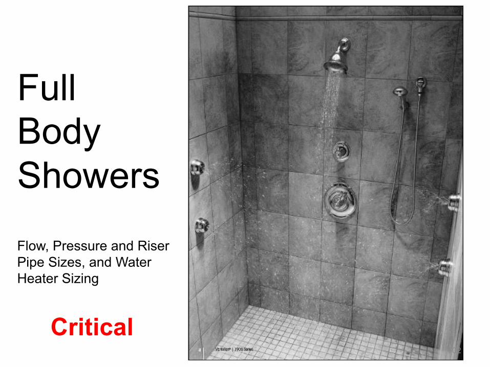
Flow, Pressure and Riser Pipe Sizes, and Water Heater Sizing
Critical
Full Body Showers
102

Canopy Showerhead
Flow, Pressure and Riser Pipe Sizes, and Water
Heater Sizing
59 psi 27.8 gallons per minute 16 x 20
Critical
103
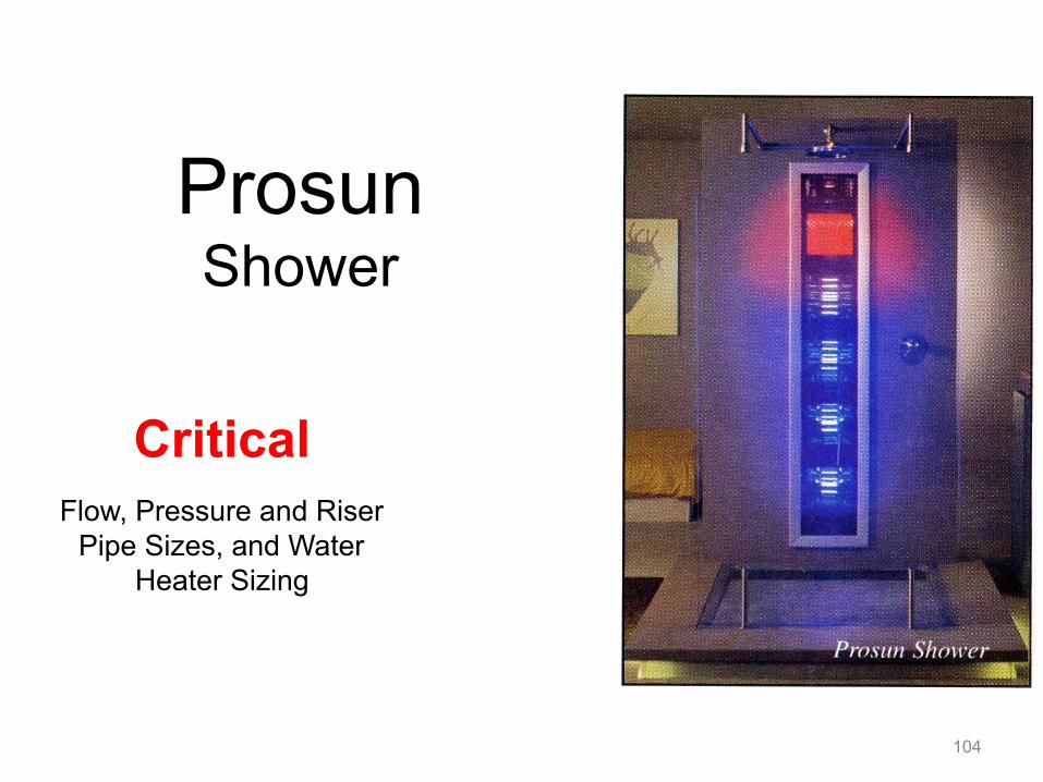
Flow, Pressure and Riser Pipe Sizes, and Water
Heater Sizing
Critical
Prosun Shower
104
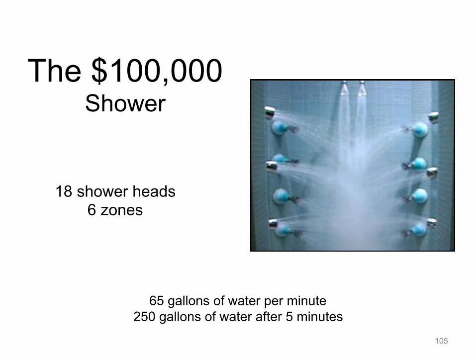
65 gallons of water per minute 250 gallons of water after 5 minutes
18 shower heads 6 zones
The $100,000 Shower
105

Is your Cooling Tower on the Roof?
106
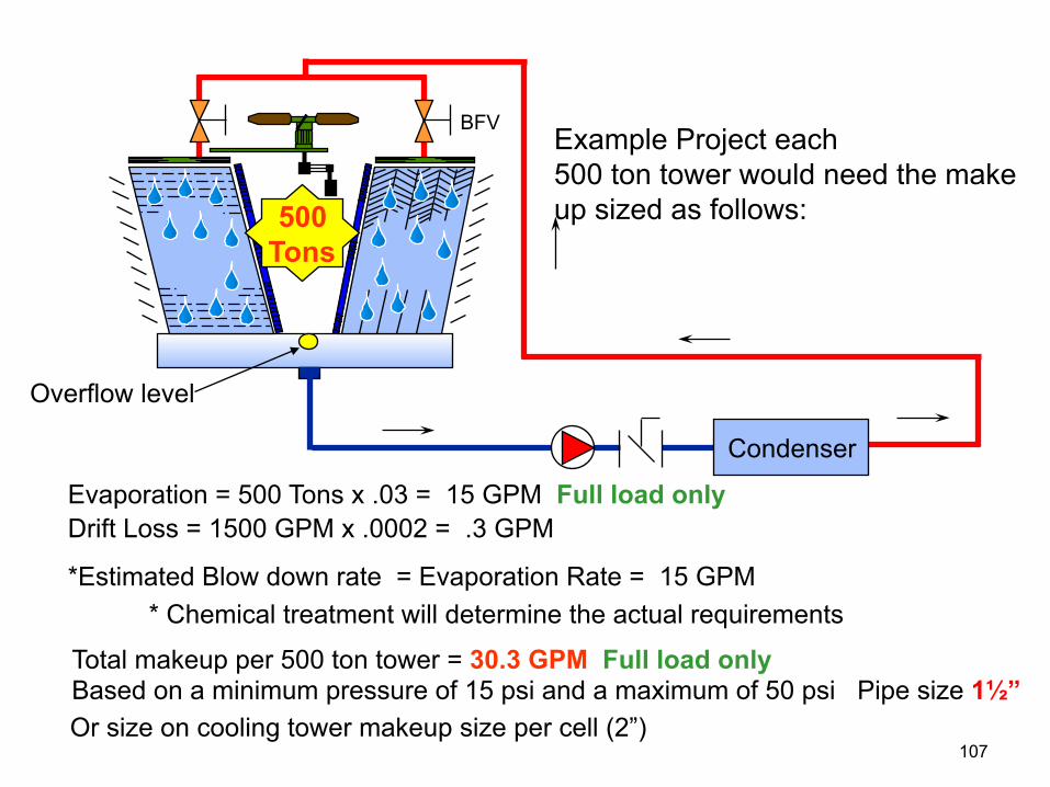
Example Project each 500 ton tower would need the make up sized as follows:
Condenser
Overflow level
BFV
500 Tons
Evaporation = 500 Tons x .03 = 15 GPM Full load only Drift Loss = 1500 GPM x .0002 = .3 GPM
*Estimated Blow down rate = Evaporation Rate = 15 GPM * Chemical treatment will determine the actual requirements
Total makeup per 500 ton tower = 30.3 GPM Full load only Based on a minimum pressure of 15 psi and a maximum of 50 psi Pipe size 1½” Or size on cooling tower makeup size per cell (2”)
107
Water closets (toilets) - flushometer valve type
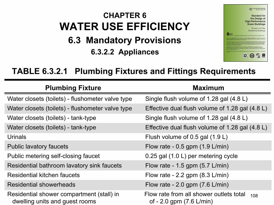
CHAPTER 6 WATER USE EFFICIENCY
TABLE 6.3.2.1 Plumbing Fixtures and Fittings Requirements
6.3.2.2 Appliances 6.3 Mandatory Provisions
Water closets (toilets) - flushometer valve type
Water closets (toilets) - tank-type Water closets (toilets) - tank-type Urinals Public lavatory faucets Public metering self-closing faucet Residential bathroom lavatory sink faucets Residential kitchen faucets Residential showerheads Residential shower compartment (stall) in dwelling units and guest rooms
Single flush volume of 1.28 gal (4.8 L) Effective dual flush volume of 1.28 gal (4.8 L) Single flush volume of 1.28 gal (4.8 L) Effective dual flush volume of 1.28 gal (4.8 L) Flush volume of 0.5 gal (1.9 L) Flow rate - 0.5 gpm (1.9 L/min) 0.25 gal (1.0 L) per metering cycle Flow rate - 1.5 gpm (5.7 L/min) Flow rate - 2.2 gpm (8.3 L/min) Flow rate - 2.0 gpm (7.6 L/min) Flow rate from all shower outlets total of - 2.0 gpm (7.6 L/min)
Plumbing Fixture Maximum
108

Required System Pressure
109
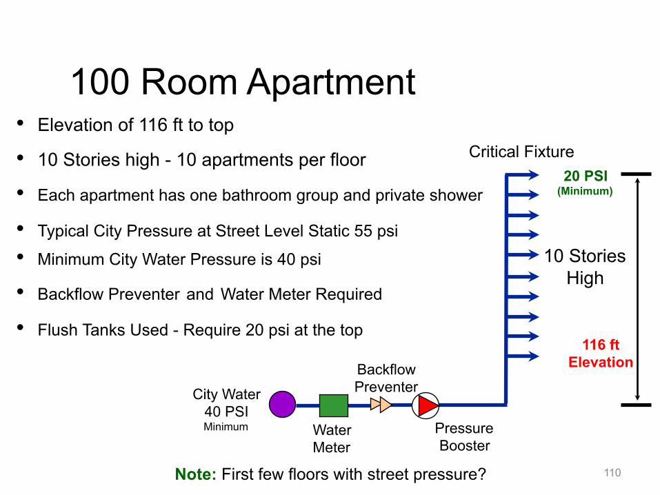
• Elevation of 116 ft to top • 10 Stories high - 10 apartments per floor • Each apartment has one bathroom group and private shower • Typical City Pressure at Street Level Static 55 psi • Minimum City Water Pressure is 40 psi • Backflow Preventer and Water Meter Required • Flush Tanks Used - Require 20 psi at the top
City Water 40 PSI Minimum Water
Meter
Backflow Preventer
Pressure Booster
10 Stories High
20 PSI (Minimum)
116 ft Elevation
Note: First few floors with street pressure?
100 Room Apartment
110
Critical Fixture
Pressure Booster Selection Procedure
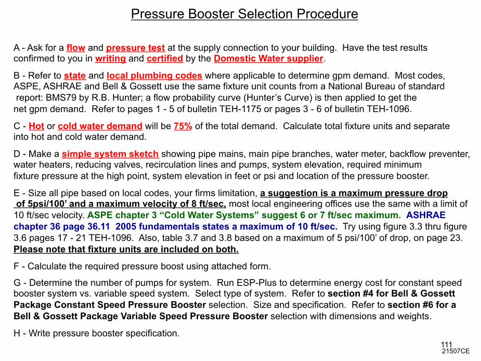
A - Ask for a flow and pressure test at the supply connection to your building. Have the test results confirmed to you in writing and certified by the Domestic Water supplier.
B - Refer to state and local plumbing codes where applicable to determine gpm demand. Most codes, ASPE, ASHRAE and Bell & Gossett use the same fixture unit counts from a National Bureau of standard report: BMS79 by R.B. Hunter; a flow probability curve (Hunter’s Curve) is then applied to get the net gpm demand. Refer to pages 1 - 5 of bulletin TEH-1175 or pages 3 - 6 of bulletin TEH-1096.
C - Hot or cold water demand will be 75% of the total demand. Calculate total fixture units and separate into hot and cold water demand.
D - Make a simple system sketch showing pipe mains, main pipe branches, water meter, backflow preventer, water heaters, reducing valves, recirculation lines and pumps, system elevation, required minimum fixture pressure at the high point, system elevation in feet or psi and location of the pressure booster.
E - Size all pipe based on local codes, your firms limitation, a suggestion is a maximum pressure drop of 5psi/100’ and a maximum velocity of 8 ft/sec, most local engineering offices use the same with a limit of 10 ft/sec velocity. ASPE chapter 3 “Cold Water Systems” suggest 6 or 7 ft/sec maximum. ASHRAE chapter 36 page 36.11 2005 fundamentals states a maximum of 10 ft/sec. Try using figure 3.3 thru figure 3.6 pages 17 - 21 TEH-1096. Also, table 3.7 and 3.8 based on a maximum of 5 psi/100’ of drop, on page 23. Please note that fixture units are included on both.
F - Calculate the required pressure boost using attached form.
G - Determine the number of pumps for system. Run ESP-Plus to determine energy cost for constant speed booster system vs. variable speed system. Select type of system. Refer to section #4 for Bell & Gossett Package Constant Speed Pressure Booster selection. Size and specification. Refer to section #6 for a Bell & Gossett Package Variable Speed Pressure Booster selection with dimensions and weights.
21507CE
H - Write pressure booster specification. 111

112 180 GPM
5 PSI
1-800-365-9010 www.jmpco.com
113
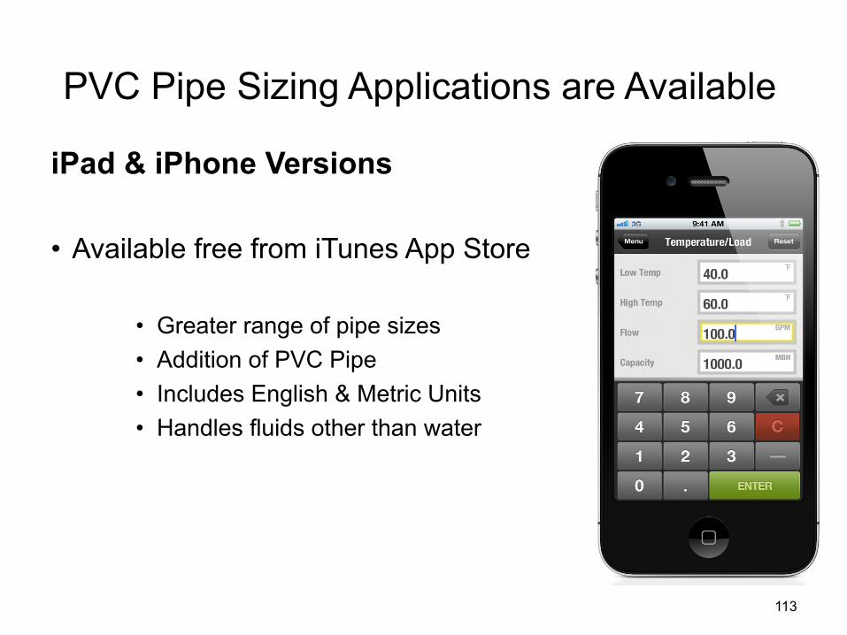
PVC Pipe Sizing Applications are Available
iPad & iPhone Versions
• Available free from iTunes App Store
• Greater range of pipe sizes • Addition of PVC Pipe • Includes English & Metric Units • Handles fluids other than water
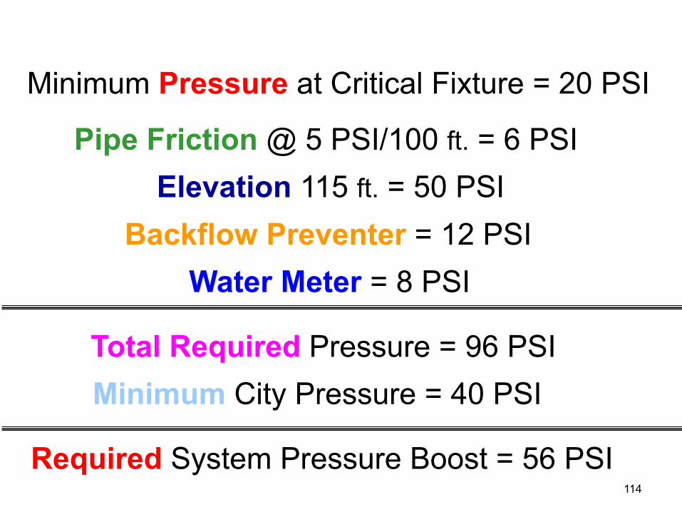
Minimum Pressure at Critical Fixture = 20 PSI
Pipe Friction @ 5 PSI/100 ft. = 6 PSI Elevation 115 ft. = 50 PSI
Backflow Preventer = 12 PSI Water Meter = 8 PSI
Total Required Pressure = 96 PSI Minimum City Pressure = 40 PSI
Required System Pressure Boost = 56 PSI 114

Minimum Pressure at the System Top ________ PSI (Pressure Drop of Greatest Pressure Drop Fixture) (Typically 20 to 25 PSI Flush Tanks and Dishwashers) (Typically 30 to 35 PSI Flush Valves) (Low Flush Valves 35 psi)
Pipe Friction at 5 PSI/100 ft Longest Run ________ PSI (Add 20% for Tees, Elbows, and Fittings)
Elevation Above Water Supply Conn. ________ PSI Divide Feet by 2.31 ft/PSI to get PSI
Water Heater if Used (2.31 ft/PSI) ________ PSI
System Pressure Reducing Valve or Check Valve ________ PSI
Back Flow Preventer (Typically 10 to 12 PSI) ________ PSI
Water Meter (Typically 5 to 6 PSI) ________ PSI
Thermostatic Mixing Valve (Typically 5 to 20 psi) ________ PSI
Miscellaneous (Pump Suction Valves, Filters, Strainers, Water Softner, etc.) ________ PSI Total Required System Pressure ________ PSI
*Minimum City Suction Pressure (-) ________ PSI
*Required System Pressure Boost ________ PSI
PSI * 2.31 ft/PSI Equals Head in Feet ________ ft Note: *Pressure Booster Selections Include The Pressure Reducing Valve Drop. *Confirm Minimum City Pressure in Writing for the Project Data File. 21507CE
Pressure Booster Selection Procedure Job Name:_____________________ Date:_____________________
Total Fixture Units ________F.U. Hunter Curve Demand ________GPM
115
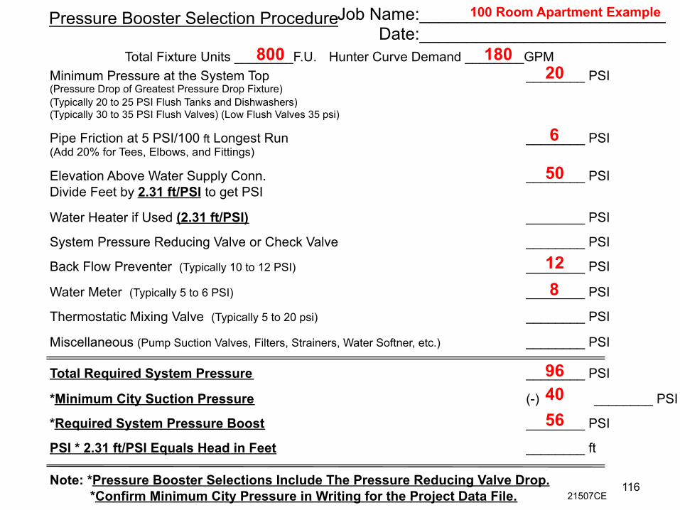
Minimum Pressure at the System Top ________ PSI (Pressure Drop of Greatest Pressure Drop Fixture) (Typically 20 to 25 PSI Flush Tanks and Dishwashers) (Typically 30 to 35 PSI Flush Valves) (Low Flush Valves 35 psi)
Pipe Friction at 5 PSI/100 ft Longest Run ________ PSI (Add 20% for Tees, Elbows, and Fittings)
Elevation Above Water Supply Conn. ________ PSI Divide Feet by 2.31 ft/PSI to get PSI
Water Heater if Used (2.31 ft/PSI) ________ PSI
System Pressure Reducing Valve or Check Valve ________ PSI
Back Flow Preventer (Typically 10 to 12 PSI) ________ PSI
Water Meter (Typically 5 to 6 PSI) ________ PSI
Thermostatic Mixing Valve (Typically 5 to 20 psi) ________ PSI
Miscellaneous (Pump Suction Valves, Filters, Strainers, Water Softner, etc.) ________ PSI Total Required System Pressure ________ PSI
*Minimum City Suction Pressure (-) ________ PSI
*Required System Pressure Boost ________ PSI
PSI * 2.31 ft/PSI Equals Head in Feet ________ ft Note: *Pressure Booster Selections Include The Pressure Reducing Valve Drop. *Confirm Minimum City Pressure in Writing for the Project Data File.
Pressure Booster Selection Procedure Job Name:__________________________ Date:__________________________
Total Fixture Units ________F.U. Hunter Curve Demand ________GPM
100 Room Apartment Example
20
6
50
12 8
96 40 56
800 180
116 21507CE

Hydro-Pneumatic Tanks
• Hydro-pneumatic tanks are primarily used in a domestic water system for draw down purposes when the pressure booster system is off on no-flow shutdown. • Without the tank, the booster would restart upon the slightest call for flow such as a single toilet being flushed • These factors prevent booster pump short cycling
Constant & Variable Boosters 117
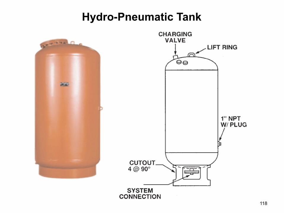
118
Hydro-Pneumatic Tank

Pump 2
Pump 1
119

Hydro-pneumatic tanks are primarily used in a domestic water system for draw down purposes when the pressure booster system is off on no-flow shutdown (NFSD). To prevent pump short cycling and to save energy.
Hydropneumatic Tank Sizing is Dependent on Two Factors
1. How long you wish to keep the pumps off in a no-flow condition. 2. The tank location in relation to the pressure booster pumps.
• Discharge Header Pressure Booster (most common)
• Top of the System (smallest tank lower working pressure) (best location)
Hydro-Pneumatic Tanks
Constant & Variable
120

To Fixtures
Located at the discharge of the pressure booster Easier to install (vs. top of system) Insure bldg pressure < tank pressure rating Typically 150 or 200 psi
Tank
Discharge Header Pressure Booster Booster size 124 GPM @ 58 PSIG
88 PSIG @ Tank (Initial Pressure)
98 PSIG @ Tank (Final Pressure)
109 Gallons
121
PRV not required for variable speed application
50
100
150
200
250
300
350
400
450
500
8
15
23
30
38
45
53
60
68
75
60
120
180
240
300
360
420
480
540
600
15
30
45
60
75
90
105
120
135
150
15
30
45
60
75
90
105
120
135
150
23
45
68
90
113
135
158
180
203
225
11
22
33
44
55
66
77
88
99
110
15
30
45
60
75
90
105
120
135
150
38
75
113
150
188
225
263
300
338
375
Tota
l Sys
tem
D
eman
d (G
PM
)
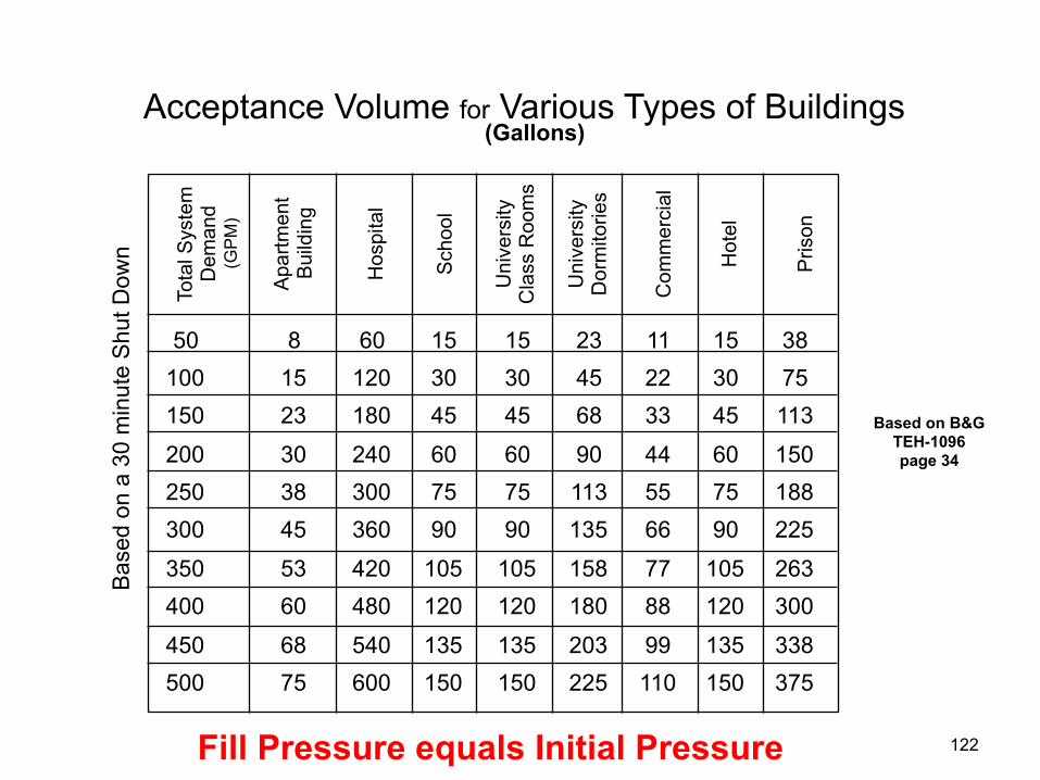
Acceptance Volume for Various Types of Buildings (Gallons)
Bas
ed o
n a
30 m
inut
e S
hut D
own
Apa
rtmen
t B
uild
ing
Hos
pita
l
Sch
ool
Uni
vers
ity
Cla
ss R
oom
s
Uni
vers
ity
Dor
mito
ries
Com
mer
cial
Hot
el
Pris
on
Fill Pressure equals Initial Pressure
Based on B&G TEH-1096 page 34
122
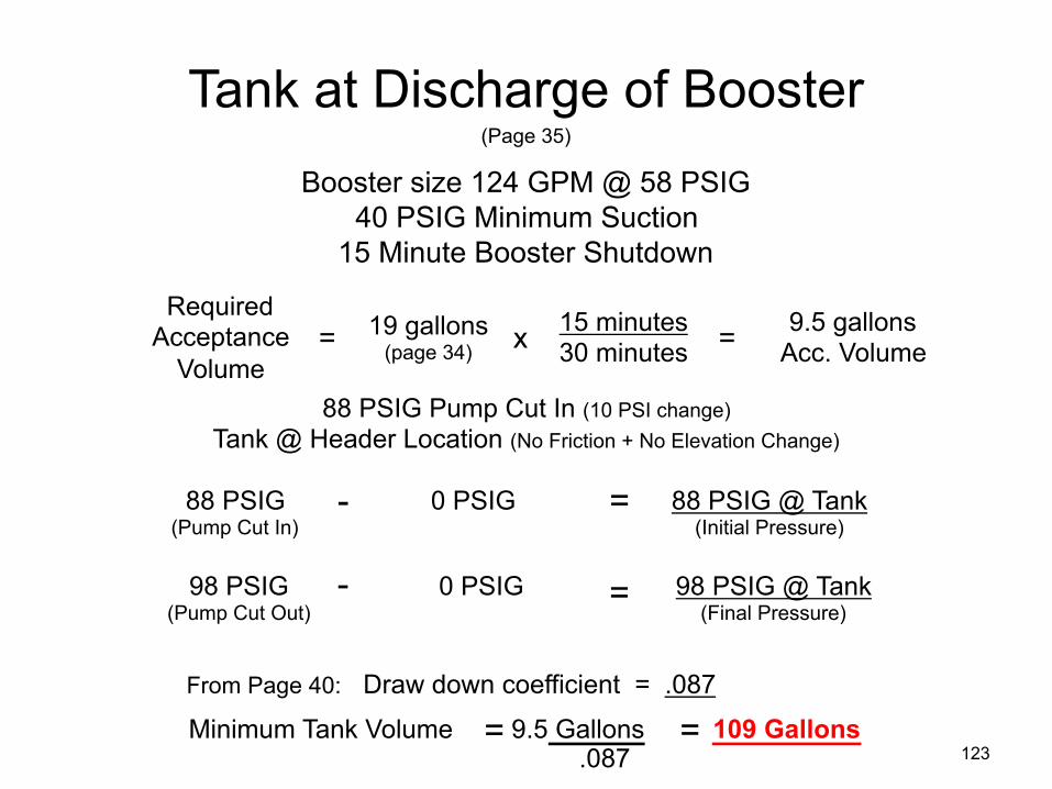
Tank at Discharge of Booster Booster size 124 GPM @ 58 PSIG
40 PSIG Minimum Suction 15 Minute Booster Shutdown
Required Acceptance
Volume 19 gallons
(page 34) 15 minutes 30 minutes
9.5 gallons Acc. Volume
88 PSIG Pump Cut In (10 PSI change) Tank @ Header Location (No Friction + No Elevation Change)
88 PSIG (Pump Cut In)
0 PSIG
88 PSIG @ Tank (Initial Pressure)
- =
- 98 PSIG (Pump Cut Out)
0 PSIG
98 PSIG @ Tank (Final Pressure)
=
= = x
From Page 40: Draw down coefficient = .087
Minimum Tank Volume 9.5 Gallons 109 Gallons = = .087
(Page 35)
123

124
Tank at High Point

125
Tank at Discharge of Booster
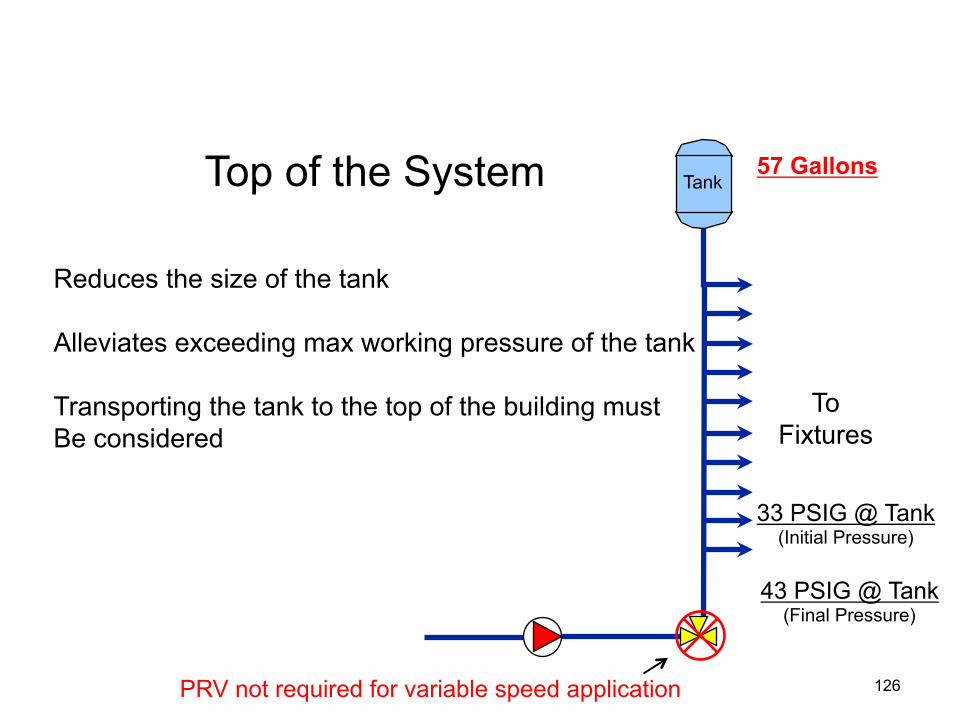
To Fixtures
Reduces the size of the tank Alleviates exceeding max working pressure of the tank Transporting the tank to the top of the building must Be considered
Tank Top of the System
57 Gallons
33 PSIG @ Tank (Initial Pressure)
43 PSIG @ Tank (Final Pressure)
126 PRV not required for variable speed application

Tank at High Point Booster size 124 GPM @ 58 PSIG
40 PSIG Minimum Suction 15 Minute Booster Shutdown
Required Acceptance
Volume 19 gallons
(page 34) 15 minutes 30 minutes
9.5 gallons Acc. Volume
88 PSIG Pump Cut In (10 PSI change) 4.7 PSI Friction + 50.2 PSI Elevation = (55 PSIG)
88 PSIG (Pump Cut In)
55 PSIG (Friction + Elevation)
33 PSIG @ Tank (Initial Pressure)
- =
- 98 PSIG (Pump Cut Out)
55 PSIG (Friction + Elevation)
43 PSIG @ Tank (Final Pressure)
=
= = x
From Page 40: Draw down coefficient = .168
Minimum Tank Volume 9.5 Gallons 57 Gallons = = .168 127
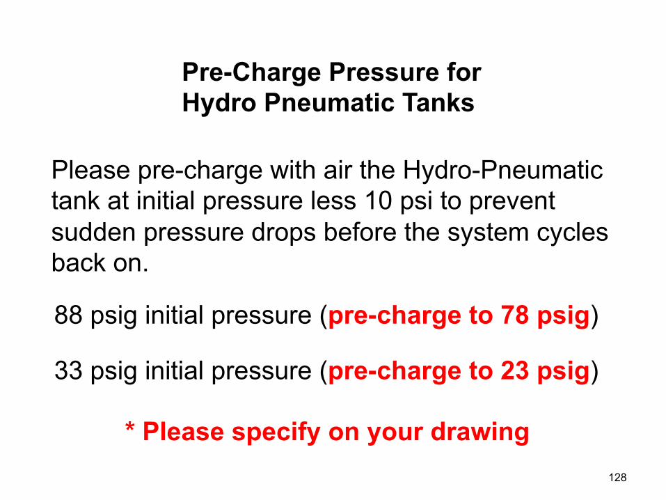
Please pre-charge with air the Hydro-Pneumatic tank at initial pressure less 10 psi to prevent sudden pressure drops before the system cycles back on.
Pre-Charge Pressure for Hydro Pneumatic Tanks
88 psig initial pressure (pre-charge to 78 psig)
33 psig initial pressure (pre-charge to 23 psig)
* Please specify on your drawing 128

606.5.10 Pressure relief for tanks. Every pressure tank in a hydropneumatic pressure booster system shall be protected with a pressure relief valve. The pressure relief valve shall be set at a maximum pressure equal to the rating of the tank. The relief valve shall be installed on the supply pipe to the tank or on the tank. The relief valve shall discharge by gravity to a safe place of disposal.
(ICC - International Plumbing Code)
Hydro Pneumatic Pressure Tank Relief
129

City Water
Water Meter
Backflow Preventer
Pressure Booster
Hydro-Pneumatic Tank
Thermal Expansion
Tank
This Application Requires Two Tanks
Water Heater
Hot Water
Cold Water
Pressure Relief Valve
130
Pressure Booster Pumping Applications
Constant Speed
vs.
Variable Speed
Considerations 131
132
ASHRAE STANDARD
ANSI/ASHRAE/IESNA/Standard 90.1-2010 (I-P Edition)
133
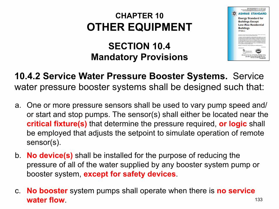
CHAPTER 10 OTHER EQUIPMENT
10.4.2 Service Water Pressure Booster Systems. Service water pressure booster systems shall be designed such that:
SECTION 10.4 Mandatory Provisions
One or more pressure sensors shall be used to vary pump speed and/or start and stop pumps. The sensor(s) shall either be located near the critical fixture(s) that determine the pressure required, or logic shall be employed that adjusts the setpoint to simulate operation of remote sensor(s).
a.
No device(s) shall be installed for the purpose of reducing the pressure of all of the water supplied by any booster system pump or booster system, except for safety devices.
b.
No booster system pumps shall operate when there is no service water flow.
c.
134
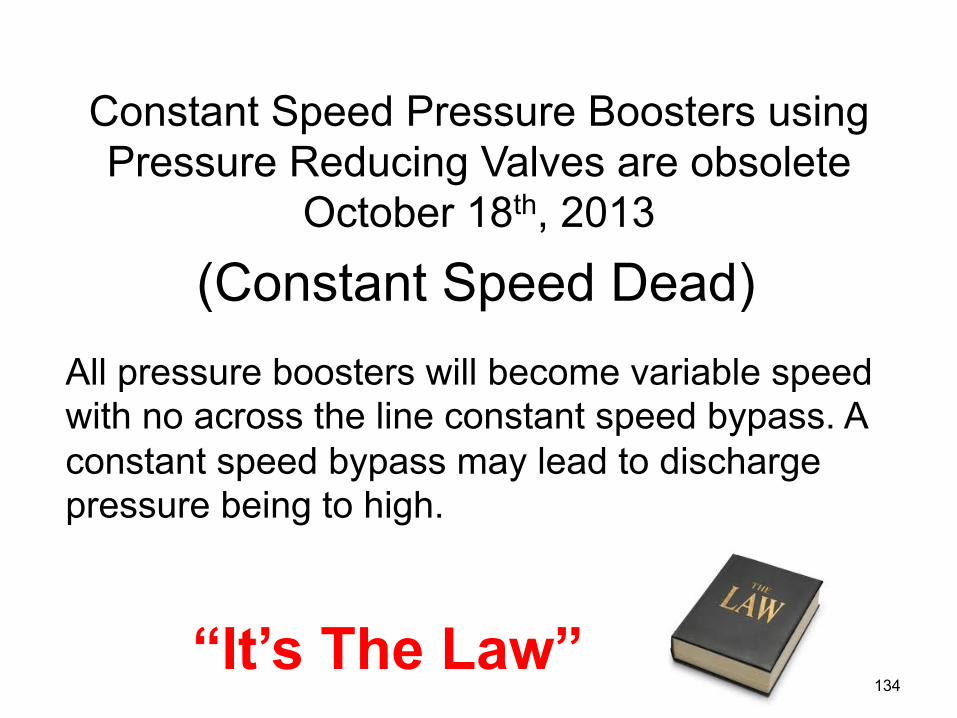
Constant Speed Pressure Boosters using Pressure Reducing Valves are obsolete
October 18th, 2013
All pressure boosters will become variable speed with no across the line constant speed bypass. A constant speed bypass may lead to discharge pressure being to high.
“It’s The Law”
(Constant Speed Dead)
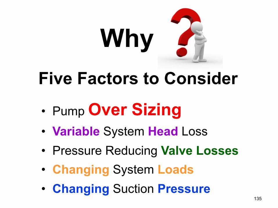
• Pump Over Sizing
• Variable System Head Loss
• Pressure Reducing Valve Losses • Changing System Loads
• Changing Suction Pressure 135
Five Factors to Consider
Why
A conservative estimate (or guess) for system flow diversity is often
used which results in an oversized pump
136
Pump Over Sizing
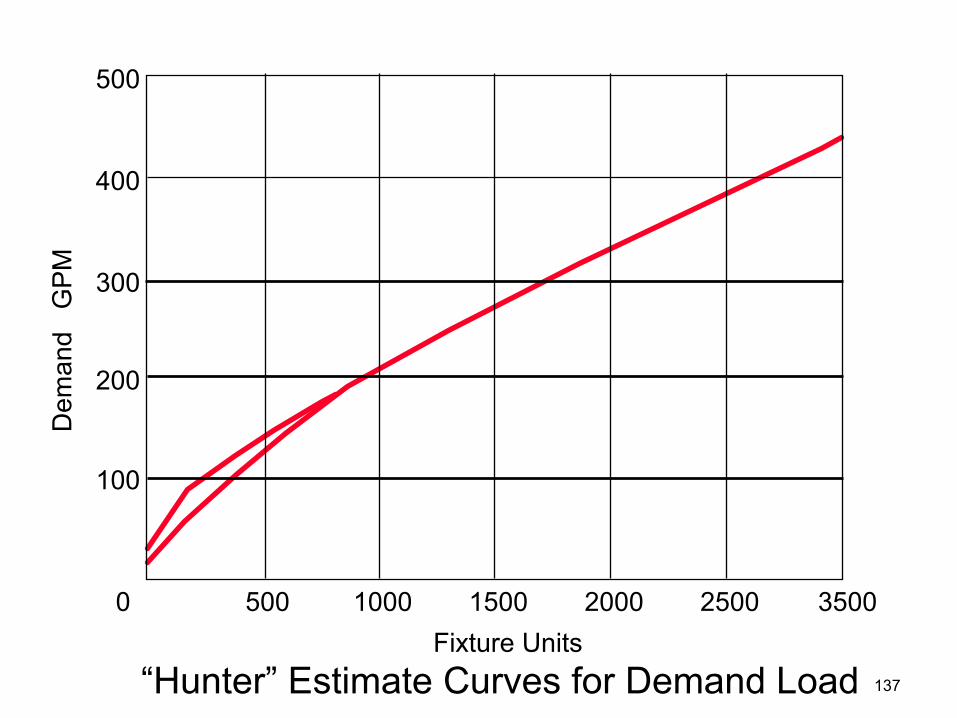
“Hunter” Estimate Curves for Demand Load Fixture Units
Dem
and
GP
M
500
400
300
200
100
0 500 1000 1500 2000 2500 3500
137

As flow decreases, friction loss also decreases.
Constant speed boosters don’t take this into account.
Variable Head Loss
138
Pressure reducing valves typically have a pressure drop of up to 5-8 psi which
must be taken into account when sizing the pump/motor.
139
PRV Pressure Drop

Booster systems experience widely varying system loads during the course of a day
140
Varying System Loads
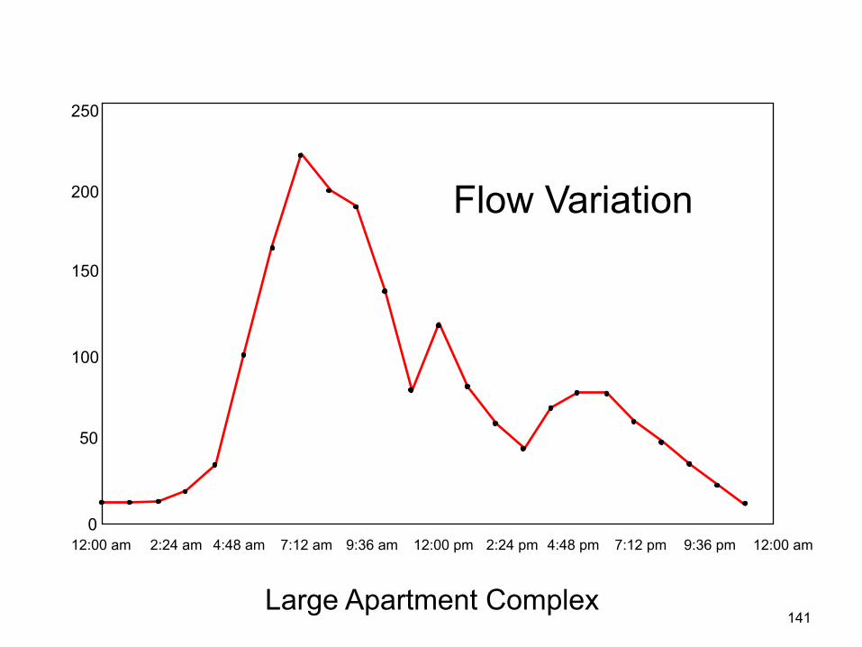
250
200
150
100
50
0 12:00 am 2:24 am 4:48 am 7:12 am 9:36 am 12:00 pm 2:24 pm 4:48 pm 7:12 pm 9:36 pm 12:00 am
Large Apartment Complex
Flow Variation
141
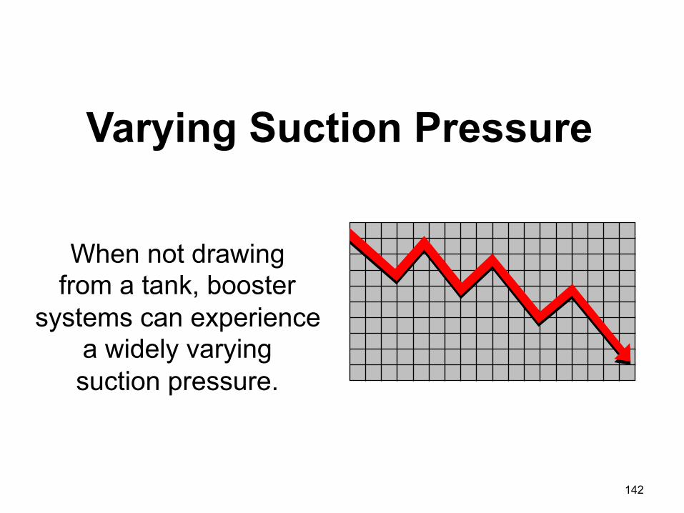
When not drawing from a tank, booster
systems can experience a widely varying suction pressure.
142
Varying Suction Pressure
Water Meter
5 PSI Drop
Backflow Preventer
10 PSI Drop
HW CW
Water Heater
Pump PRV
HW CW
Water Heater
HW CW
City Main
35 PSIG Minimum
Pressure Booster System
74 PSIG
Water Heater
30 PSIG
Administration and bed tower
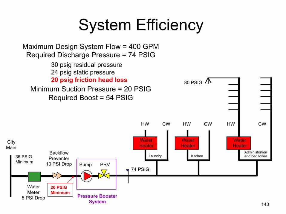
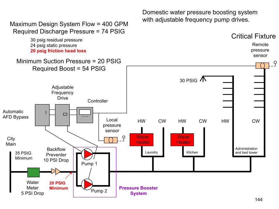
Maximum Design System Flow = 400 GPM Required Discharge Pressure = 74 PSIG
Minimum Suction Pressure = 20 PSIG Required Boost = 54 PSIG
System Efficiency
Kitchen Laundry
30 psig residual pressure 24 psig static pressure 20 psig friction head loss
20 PSIG Minimum
143
Local pressure sensor
Pump 2
Water Meter
5 PSI Drop
Backflow Preventer
10 PSI Drop
HW CW
Water Heater
HW CW
Water Heater
HW CW
City Main
35 PSIG Minimum
Pressure Booster System
30 PSIG
Administration and bed tower
Maximum Design System Flow = 400 GPM Required Discharge Pressure = 74 PSIG
Minimum Suction Pressure = 20 PSIG Required Boost = 54 PSIG
Domestic water pressure boosting system with adjustable frequency pump drives.
Kitchen Laundry
30 psig residual pressure 24 psig static pressure 20 psig friction head loss
Automatic AFD Bypass
Adjustable Frequency
Drive Controller
Pump 1
Remote pressure sensor
20 PSIG Minimum
144
Critical Fixture
Effi
cien
cy, p
erce
nt
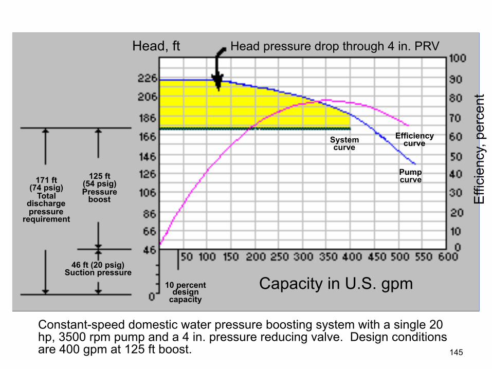
Head, ft Head pressure drop through 4 in. PRV
System curve
Efficiency curve
Pump curve
Capacity in U.S. gpm
125 ft (54 psig) Pressure
boost
171 ft (74 psig)
Total discharge pressure
requirement
46 ft (20 psig) Suction pressure
10 percent design
capacity
Constant-speed domestic water pressure boosting system with a single 20 hp, 3500 rpm pump and a 4 in. pressure reducing valve. Design conditions are 400 gpm at 125 ft boost. 145
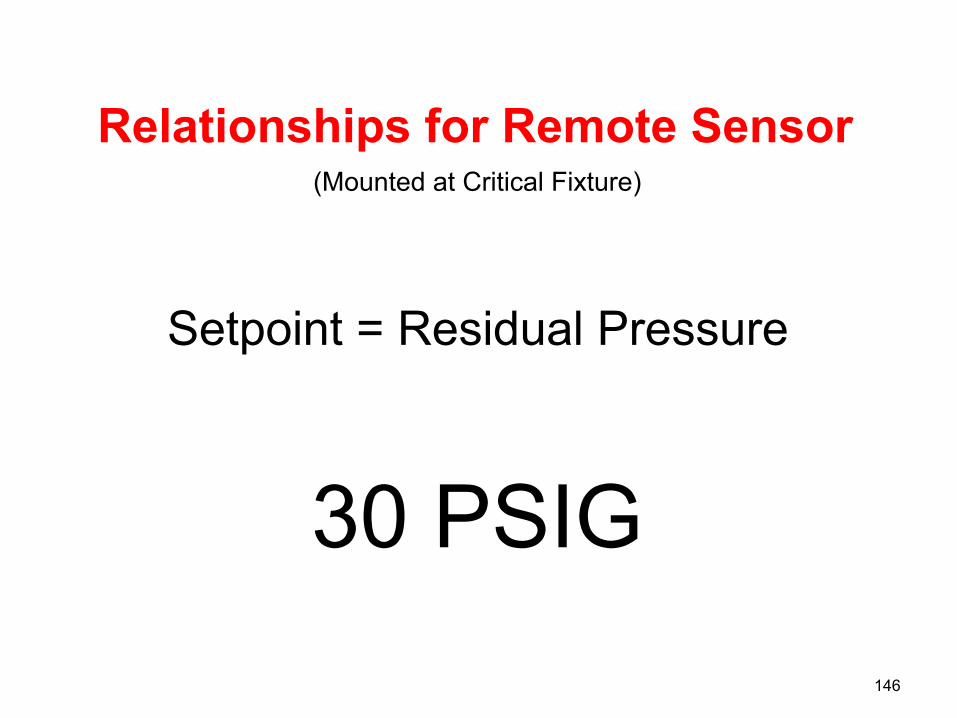
Relationships for Remote Sensor
Setpoint = Residual Pressure
146
(Mounted at Critical Fixture)
30 PSIG

Local pressure sensor
Pump 2
Water Meter
5 PSI Drop
Backflow Preventer
10 PSI Drop
HW CW
Water Heater
HW CW
Water Heater
HW CW
City Main
35 PSIG Minimum
Pressure Booster System
30 PSIG
Administration and bed tower
Maximum Design System Flow = 400 GPM Required Discharge Pressure = 74 PSIG
Minimum Suction Pressure = 20 PSIG Required Boost = 54 PSIG
Domestic water pressure boosting system with adjustable frequency pump drives.
Kitchen Laundry
30 psig residual pressure 24 psig static pressure 20 psig friction head loss
Automatic AFD Bypass
Adjustable Frequency
Drive Controller
Pump 1
Remote pressure sensor
20 PSIG Minimum
147
Critical Fixture
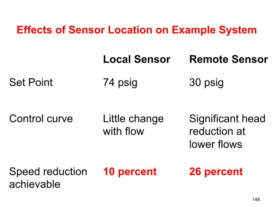
Effects of Sensor Location on Example System
148
Local Sensor Remote Sensor
Set Point 74 psig 30 psig
Control curve Little change with flow
Significant head reduction at lower flows
Speed reduction achievable
10 percent 26 percent
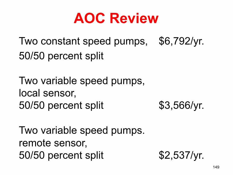
AOC Review
Two constant speed pumps, $6,792/yr. 50/50 percent split Two variable speed pumps, local sensor, 50/50 percent split $3,566/yr. Two variable speed pumps. remote sensor, 50/50 percent split $2,537/yr.
149
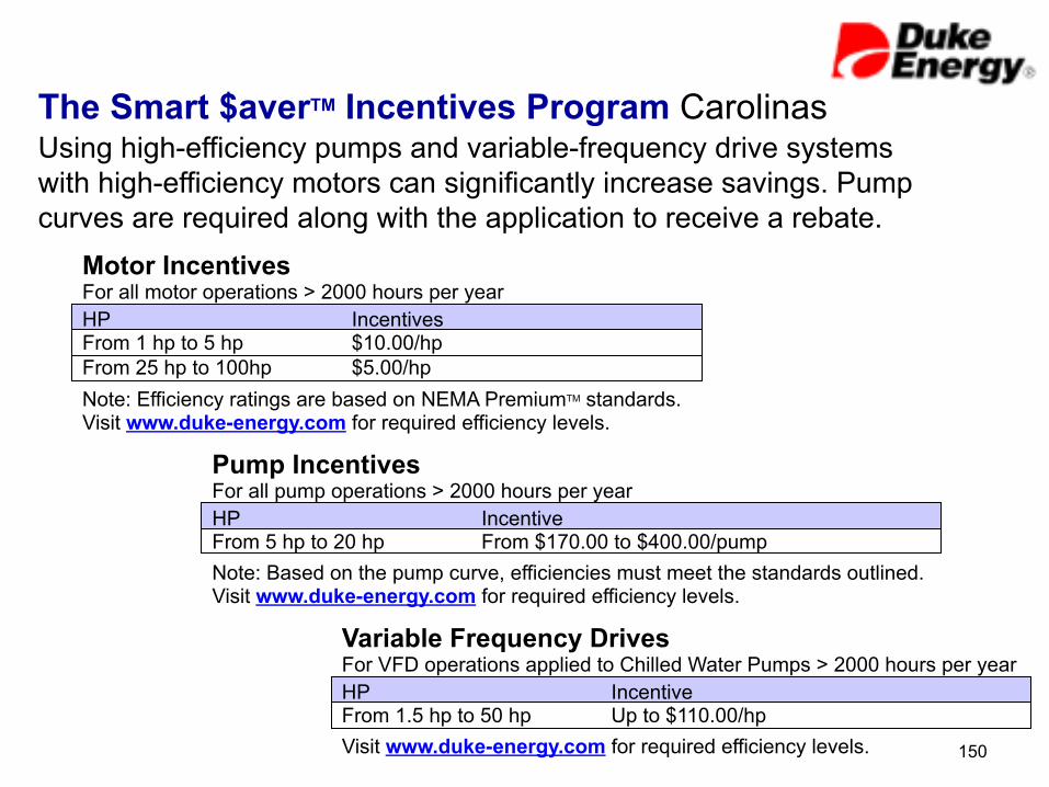
The Smart $averTM Incentives Program Carolinas Using high-efficiency pumps and variable-frequency drive systems with high-efficiency motors can significantly increase savings. Pump curves are required along with the application to receive a rebate.
Motor Incentives For all motor operations > 2000 hours per year HP From 1 hp to 5 hp From 25 hp to 100hp
Incentives $10.00/hp $5.00/hp
Note: Efficiency ratings are based on NEMA PremiumTM standards. Visit www.duke-energy.com for required efficiency levels.
Pump Incentives For all pump operations > 2000 hours per year HP From 5 hp to 20 hp
Incentive From $170.00 to $400.00/pump
Note: Based on the pump curve, efficiencies must meet the standards outlined. Visit www.duke-energy.com for required efficiency levels.
Variable Frequency Drives For VFD operations applied to Chilled Water Pumps > 2000 hours per year HP From 1.5 hp to 50 hp
Incentive Up to $110.00/hp
Visit www.duke-energy.com for required efficiency levels. 150
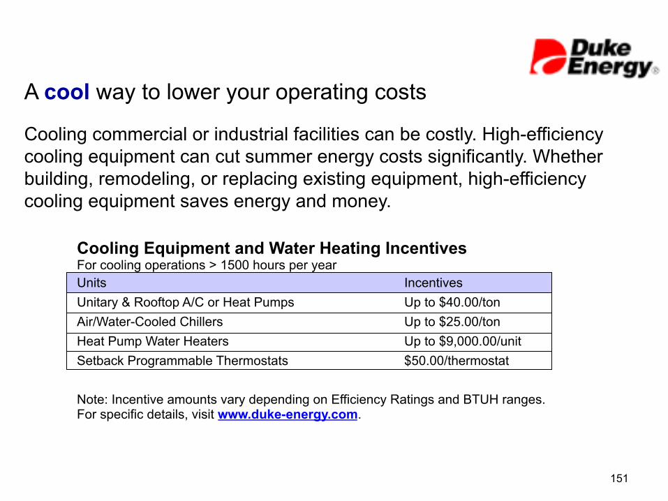
A cool way to lower your operating costs
Cooling commercial or industrial facilities can be costly. High-efficiency cooling equipment can cut summer energy costs significantly. Whether building, remodeling, or replacing existing equipment, high-efficiency cooling equipment saves energy and money.
Cooling Equipment and Water Heating Incentives For cooling operations > 1500 hours per year Units Unitary & Rooftop A/C or Heat Pumps Air/Water-Cooled Chillers Heat Pump Water Heaters Setback Programmable Thermostats
Incentives Up to $40.00/ton Up to $25.00/ton Up to $9,000.00/unit $50.00/thermostat
Note: Incentive amounts vary depending on Efficiency Ratings and BTUH ranges. For specific details, visit www.duke-energy.com.
151

152
ASHRAE STANDARD
ANSI/ASHRAE/IESNA/Standard 90.1-2010 (I-P Edition)

153
WASHINGTON—ASHRAE's Washington office is reporting that the U.S. Department of Energy (DOE) has determined that ANSI/ASHRAE/IES Standard 90.1-2010, Energy Standard for Buildings Except Low-Rise Residential Buildings, saves more energy than Standard 90.1-2007. Specifically, DOE found national source energy savings of approximately 18.2%, and site energy savings of approximately 18.5%, when comparing the 2010 and 2007 versions of Standard 90.1. As a result of this week's DOE final determination, states are required to certify by Oct. 18, 2013 that that have reviewed the provisions of their commercial building code regarding energy efficiency and updated their code to meet or exceed Standard 90.1-2010.
States to Use 90.1-2010 by Oct. 18, 2013

154
CHAPTER 10 OTHER EQUIPMENT
10.4.2 Service Water Pressure Booster Systems. Service water pressure booster systems shall be designed such that:
SECTION 10.4 Mandatory Provisions
One or more pressure sensors shall be used to vary pump speed and/or start and stop pumps. The sensor(s) shall either be located near the critical fixture(s) that determine the pressure required, or logic shall be employed that adjusts the setpoint to simulate operation of remote sensor(s).
a.
No device(s) shall be installed for the purpose of reducing the pressure of all of the water supplied by any booster system pump or booster system, except for safety devices.
b.
No booster system pumps shall operate when there is no service water flow.
c.

Required Addition to all Pressure Booster Master Specifications
155
To meet ASHRAE 90.1-2010 standard and DOE building code requirement by October 18th, 2013 the variable speed pressure booster shall control to a remote sensor at the critical fixture or logic to vary the local discharge pressure setpoint based on demand to simulate the operation of a remote sensor.
“It’s The Law”

Web Site: http://www.jmpco.com
Thank you for coming!
156