Hangers and Supports CEU 252 - ASPE · PDF fileand with the pipe and pipe support...
20
CEU 252 Hangers and Supports Continuing Education from the American Society of Plumbing Engineers October 2017 ASPE.ORG/ReadLearnEarn
-
Upload
nguyencong -
Category
Documents
-
view
225 -
download
7
Transcript of Hangers and Supports CEU 252 - ASPE · PDF fileand with the pipe and pipe support...
CEU
252
Hangers and Supports
Continuing Education from the American Society of Plumbing Engineers
October 2017
ASPE.ORG/ReadLearnEarn
Piping system supports and hangers perform many functions—including supporting or anchoring piping systems, preventing pipe runs from sagging, allowing for motion to alleviate breakage, and providing adequate slope to accommodate drainage or flow—and they are an integral part of plumbing systems. Choosing the correct supports and hangers is an important aspect of the design of a plumbing system, as improper specification can lead to failure of the entire system. The designer must consider a multitude of environmental and physical characteristics that may interact with and affect the overall system, such as the quantity and composition of the fluid expected to flow through the piping, structural components, chemical interactions, metal fatigue analysis, acoustics, and even electric current transference. The specification must go beyond the support types and hanger distances prescribed in the plumbing codes. In fact, the designer may need to consult with other engineering disciplines and with the pipe and pipe support manufacturers for the correct materials to specify for particular applications.
HANGER AND SUPPORT CONSIDERATIONSThe most common hanger and support detail specified on plans is a simple statement: “The piping shall be supported in a good and substantial manner in accordance with all local codes and ordinances.” However, the codes typically provide little help to the plumbing engineer, as the requirements are simple—for example:
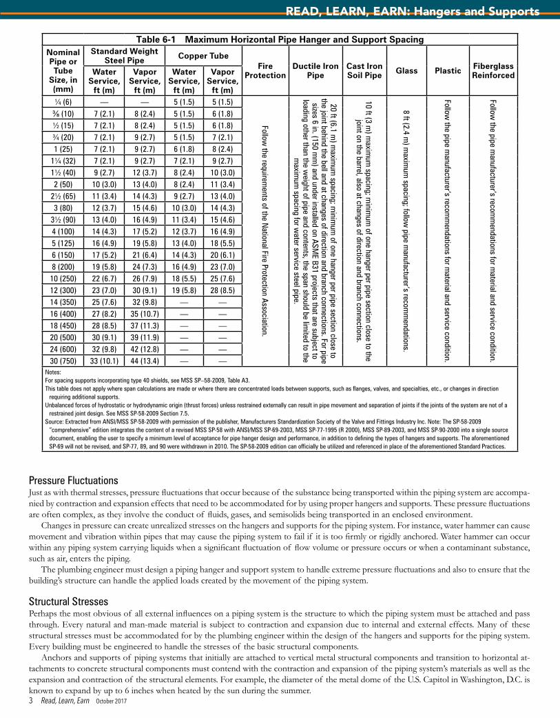
• All water piping shall be adequately supported to the satisfaction of the administrative authority.• Piping shall be supported for the weight and the design of the material used.• Supports, hangers, and anchors are devices for properly supporting and securing pipe, fixtures, and equipment.• Suspended piping shall be supported at intervals not to exceed those shown in Table 6-1.• All piping shall be supported in such a manner as to maintain its alignment and prevent sagging.• Hangers and anchors shall be of sufficient strength to support the weight of the pipe and its contents. • Piping shall be isolated from incompatible materials.A technical specification or performance characteristic regarding piping support is an often-overlooked part of the plumbing system design.
In addition to following the basic code requirements, the plumbing engineer must study, evaluate, and analyze the piping layout in relation to the structure and equipment, as well as consider the totality of the piping systems that will be utilized and the surrounding environmental and physical characteristics that will come to bear on the overall performance of the completed system. Given the wide variety of environmental and physical characteristics around which projects are designed, it is not possible to provide an exhaustive listing of potential areas that need evaluation. However, some basic considerations include the following.
LoadsWhat will be the total load of the piping system? First and foremost, basic engineering requires a performance and load calculation to be con-ducted to determine the physical amount and weight of all specific piping system elements. In this initial determination, the engineer considers not only the weight of the piping itself, but also that of all associated elements including valves, fittings, the bulk weight and flow characteristics of the substance to flow through or be carried within the pipe, and thermal or acoustical insulation or other pipe-covering material.
Depending on the piping system’s location, other natural and man-made forces that may create an additional load on the piping system, such as rain, ice, and snow for piping systems exposed to natural weather conditions, also must be considered. When a portion of the piping system will be exposed and relatively easy to reach, the engineer should give some consideration to the potential for unintended uses, such as people hanging from pipes or using them as supports for various items (e.g., plants, lights). The chosen hanger, support, and anchor system must, at a minimum, accommodate the piping system load. Moreover, the plumbing engineer needs to work closely with the structural engineer to ensure that the building’s structure will be able to support the load created by the attachment of the piping system. This load calculation also may incorporate other elements as indicated below.
Thermal StressesWhat stresses and accompanying limitations will be imposed on the piping system? Many external, internal, and thermal stresses and the accom-panying movements that can occur need to be accommodated by the hangers, supports, and anchors of a piping system. Hangers and supports must provide for flexibility and axial (twisting), latitudinal, and longitudinal motions.
Thermal events subject the piping system to both internal and external influences, resulting in contractions and expansions, which can be gradual or sudden in their movements. These contracting and expanding movements can be caused by temperature fluctuations in the piping system. Pipe systems experience dimension changes due to a change in temperature, and piping systems subject to these temperature changes will experience thermal stress conditions, which can exert forces and moments on the piping system. The hangers must be able to accommodate the effects of thermal stress by either expansion joints and/or by installing anchors and guides to allow for movement.
Reprinted from Plumbing Engineering Design Handbook, Volume 4. © 2016, American Society of Plumbing Engineers. All rights reserved.
Note: In determining your answers to the CE questions, use only the material presented in the corresponding continuing education article. Using information from other materials may result in a wrong answer.
2 Read, Learn, Earn October 2017
READ, LEARN, EARN
Pressure FluctuationsJust as with thermal stresses, pressure fluctuations that occur because of the substance being transported within the piping system are accompa-nied by contraction and expansion effects that need to be accommodated for by using proper hangers and supports. These pressure fluctuations are often complex, as they involve the conduct of fluids, gases, and semisolids being transported in an enclosed environment.
Changes in pressure can create unrealized stresses on the hangers and supports for the piping system. For instance, water hammer can cause movement and vibration within pipes that may cause the piping system to fail if it is too firmly or rigidly anchored. Water hammer can occur within any piping system carrying liquids when a significant fluctuation of flow volume or pressure occurs or when a contaminant substance, such as air, enters the piping.
The plumbing engineer must design a piping hanger and support system to handle extreme pressure fluctuations and also to ensure that the building’s structure can handle the applied loads created by the movement of the piping system.
Structural StressesPerhaps the most obvious of all external influences on a piping system is the structure to which the piping system must be attached and pass through. Every natural and man-made material is subject to contraction and expansion due to internal and external effects. Many of these structural stresses must be accommodated for by the plumbing engineer within the design of the hangers and supports for the piping system. Every building must be engineered to handle the stresses of the basic structural components.
Anchors and supports of piping systems that initially are attached to vertical metal structural components and transition to horizontal at-tachments to concrete structural components must contend with the contraction and expansion of the piping system’s materials as well as the expansion and contraction of the structural elements. For example, the diameter of the metal dome of the U.S. Capitol in Washington, D.C. is known to expand by up to 6 inches when heated by the sun during the summer.
Table 6-1 Maximum Horizontal Pipe Hanger and Support SpacingNominal Pipe or Tube
Size, in (mm)
Standard Weight Steel Pipe Copper Tube
Fire Protection
Ductile Iron Pipe
Cast Iron Soil Pipe Glass Plastic Fiberglass
ReinforcedWater Service,
ft (m)
Vapor Service,
ft (m)
Water Service,
ft (m)
Vapor Service,
ft (m)¼ (6) — — 5 (1.5) 5 (1.5)
Follow the requirem
ents of the National Fire Protection Association.
20 ft (6.1 m) m
aximum
spacing; minim
um of one hanger per pipe section close to
the joint behind the bell and at changes of direction and branch connections. For pipe sizes 6 in. (150 m
m) and under installed on ASM
E B31 projects that are subject to loading other than the w
eight of pipe and contents, the span should be limited to the
maxim
um spacing for w
ater service steel pipe.
10 ft (3 m) m
aximum
spacing; minim
um of one hanger per pipe section close to the
joint on the barrel, also at changes of direction and branch connections.
8 ft (2.4 m) m
aximum
spacing; follow pipe m
anufacturer’s recomm
endations.
Follow the pipe m
anufacturer’s recomm
endations for material and service condition.
Follow the pipe m
anufacturer’s recomm
endations for material and service condition.
⅜ (10) 7 (2.1) 8 (2.4) 5 (1.5) 6 (1.8)½ (15) 7 (2.1) 8 (2.4) 5 (1.5) 6 (1.8)¾ (20) 7 (2.1) 9 (2.7) 5 (1.5) 7 (2.1)1 (25) 7 (2.1) 9 (2.7) 6 (1.8) 8 (2.4)
1¼ (32) 7 (2.1) 9 (2.7) 7 (2.1) 9 (2.7)1½ (40) 9 (2.7) 12 (3.7) 8 (2.4) 10 (3.0)2 (50) 10 (3.0) 13 (4.0) 8 (2.4) 11 (3.4)
2½ (65) 11 (3.4) 14 (4.3) 9 (2.7) 13 (4.0)3 (80) 12 (3.7) 15 (4.6) 10 (3.0) 14 (4.3)
3½ (90) 13 (4.0) 16 (4.9) 11 (3.4) 15 (4.6)4 (100) 14 (4.3) 17 (5.2) 12 (3.7) 16 (4.9)5 (125) 16 (4.9) 19 (5.8) 13 (4.0) 18 (5.5)6 (150) 17 (5.2) 21 (6.4) 14 (4.3) 20 (6.1)8 (200) 19 (5.8) 24 (7.3) 16 (4.9) 23 (7.0)10 (250) 22 (6.7) 26 (7.9) 18 (5.5) 25 (7.6)12 (300) 23 (7.0) 30 (9.1) 19 (5.8) 28 (8.5)14 (350) 25 (7.6) 32 (9.8) — —16 (400) 27 (8.2) 35 (10.7) — —18 (450) 28 (8.5) 37 (11.3) — —20 (500) 30 (9.1) 39 (11.9) — —24 (600) 32 (9.8) 42 (12.8) — —30 (750) 33 (10.1) 44 (13.4) — —
Notes:For spacing supports incorporating type 40 shields, see MSS SP–58-2009, Table A3.This table does not apply where span calculations are made or where there are concentrated loads between supports, such as flanges, valves, and specialties, etc., or changes in direction
requiring additional supports.Unbalanced forces of hydrostatic or hydrodynamic origin (thrust forces) unless restrained externally can result in pipe movement and separation of joints if the joints of the system are not of a
restrained joint design. See MSS SP-58-2009 Section 7.5.Source: Extracted from ANSI/MSS SP-58-2009 with permission of the publisher, Manufacturers Standardization Society of the Valve and Fittings Industry Inc. Note: The SP-58-2009
“comprehensive” edition integrates the content of a revised MSS SP-58 with ANSI/MSS SP-69-2003, MSS SP-77-1995 (R 2000), MSS SP-89-2003, and MSS SP-90-2000 into a single source document, enabling the user to specify a minimum level of acceptance for pipe hanger design and performance, in addition to defining the types of hangers and supports. The aforementioned SP-69 will not be revised, and SP-77, 89, and 90 were withdrawn in 2010. The SP-58-2009 edition can officially be utilized and referenced in place of the aforementioned Standard Practices.
3 Read, Learn, Earn October 2017
READ, LEARN, EARN: Hangers and Supports
Natural Environmental ConditionsThe susceptibility of a piping system to natural conditions must be accounted for within the piping system and the accompanying hangers, sup-ports, and anchors. The major effect of these natural environmental conditions is on the basic building structure. However, within structures designed to handle extreme natural phenomena, the piping system itself must be hardened or conditioned.
Typical natural phenomena consist of seismic forces and sustained periods of high winds, including hurricanes and typhoons, which create major stresses and loads on a building’s structure. For instance, an extreme high-rise building, such as the Empire State Building in New York City, can move 4 to 12 inches laterally in high winds. In zones of known natural phenomena, such as areas susceptible to earth movement, the plumbing engineer must design the piping and support systems to sustain the shocks, stresses, and loads inherent with and applied by these extreme forces. The engineer must refer to the applicable building codes to determine the seismic design category for any mandated piping system support requirements.
While a plumbing system may not be expected to survive the complete destruction of a building’s structure, it is expected to survive intact and working in the event that the building structure itself survives.
Reactivity and Conductivity The hangers and supports vital to providing piping system integrity often must also provide protection from unexpected natural and man-made activities, events, and phenomena totally unrelated to the structure, stresses, loads, and similar engineering events. Just as designers must consider the makeup of the interior surfaces of the piping material, they also must consider the exterior components of the piping system that will be subject to environmental and man-made conditions. The hangers and supports must be factored into this reactive equation.
Reactive conditions can consist of chemical reactions between unlike materials or the introduction of a reactive substance or electrical conductivity that can occur between different materials due to electrical leakage onto a piping system. These reactive and conductivity concerns can be unobtrusive and unexpected. Regardless, they can be the cause of unexpected failure in the hangers or supports of the piping system.
This type of failure can be especially acute in unexpected areas. Chemical fumes, salt water, and cleaning liquids can cause a chemical reaction between a hanger or support and a pipe of differing metals. Initial indicators of potential failure can be seen in corrosion or in the compounds produced by a chemical reaction that attach to the hangers and supports in inhospitable environments such as boiler rooms or specialty gas and liquid systems. Another corrosive environment is natatoriums, where chlorine or other chemicals used for indoor pools can affect the hangers and supports (i.e., the presence of chloramines contributes to the corrosion of stainless steel).
It is vital that such reactive conditions be considered and that the engineer specify compatible pipe and support materials or provide for pro-tective coatings or materials. It is especially important to ensure that the interior portions of hangers, supports, and clamps that come in contact with piping also are subject to the protective coatings; otherwise, they will be prone to failure as the material is destroyed from the inside out.
Similarly, electrical current seepage or leakage can cause unexpected but known effects between two dissimilar materials. The plumbing en-gineer may need to evaluate the potential for this electrical leakage, especially in common raceways where piping and conduit are placed side by side, and provide suitable protection via the hangers and supports. A common example of this is the galvanic corrosion that occurs in copper pipe when steel hangers are used.
AcousticsFor certain structures, the engineer may need to consider various acoustical aspects related to piping systems. In general, two significant types of acoustical annoyances must be considered. The first is noise, such as the sound of liquid rushing through a pipe or a harmonic resonance that makes a pipe ring. In these instances, the engineer must ensure that the piping system and the accompanying supports receive proper insulation.
The second type of acoustic effect that must be considered is that created by vibration and movement within the piping system. This acoustic anomaly requires a hanger and support system that offers a combination of three-dimensional flexibility to account for lateral, longitudinal, and axial movements of the piping system and a sound- and vibration-insulating material or anchor integrated into the hanger.
Man-Made Environmental ConditionsThe plumbing designer also should be cognizant of any man-made environmental conditions that can affect the piping system. These created conditions can cause uncalculated stresses and loads on the system and lead to premature failure. Created environmental conditions that can result in resonance or vibration affecting interior structural systems include major highway arteries with significant automotive and truck traf-fic, airport takeoff and landing patterns, nearby construction, underground digging, and underground traffic such as subways. Other manmade environments can be where temperatures and humidities are above the normal conditions, such as in natatoriums and arboretums.
HANGER AND SUPPORT SELECTION AND INSTALLATIONThe old adage “the whole is only as strong as its individual parts” applies directly to piping hangers and supports. Countless environmental and physical conditions as discussed above can be considered when choosing the correct hanger, support, or anchor. Nothing, however, substitutes for experience and knowledge. The engineer should work directly with the pipe manufacturer regarding the proper spacing criteria and hang-ing methods for the pipe that is to be specified. While the number of variables that can be examined in choosing hangers and supports for a plumbing system has no limits, practicality and resource limitations also must be taken into consideration.
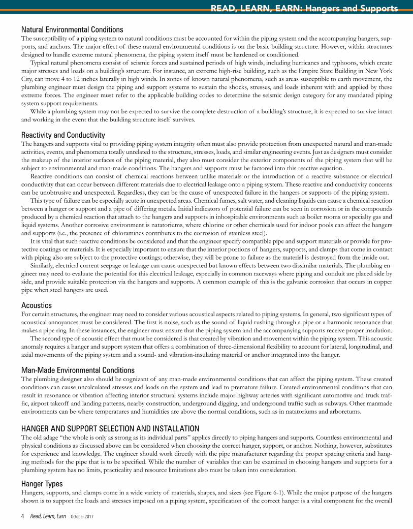
Hanger TypesHangers, supports, and clamps come in a wide variety of materials, shapes, and sizes (see Figure 6-1). While the major purpose of the hangers shown is to support the loads and stresses imposed on a piping system, specification of the correct hanger is a vital component for the overall
4 Read, Learn, Earn October 2017
READ, LEARN, EARN: Hangers and Supports
structural integrity of the building itself. The structure must be able to handle the loads and stresses of the piping system, and the hanger and support system must be engineered to provide flexibility, durability, and structural strength.
Selection CriteriaTo ensure proper hanger and support selection, the plumbing engineer must determine or be cognizant of the degrees of freedom that will be necessary within the piping system due to its operating characteristics. These degrees of freedom need to be considered in a three-dimensional space to account for lateral, horizontal, vertical, and axial movements and fluctuations.
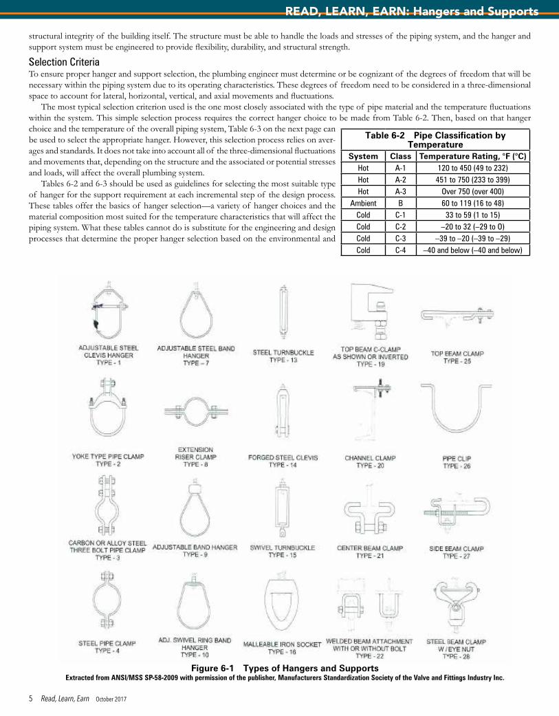
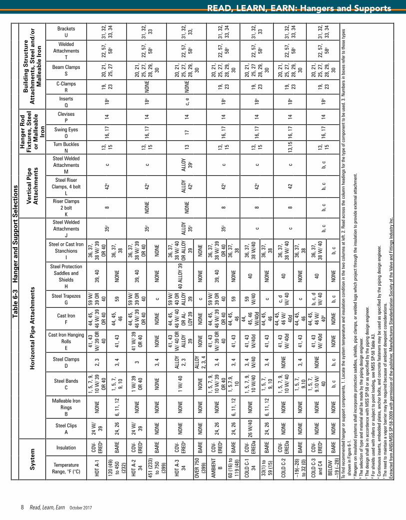
The most typical selection criterion used is the one most closely associated with the type of pipe material and the temperature fluctuations within the system. This simple selection process requires the correct hanger choice to be made from Table 6-2. Then, based on that hanger choice and the temperature of the overall piping system, Table 6-3 on the next page can be used to select the appropriate hanger. However, this selection process relies on aver-ages and standards. It does not take into account all of the three-dimensional fluctuations and movements that, depending on the structure and the associated or potential stresses and loads, will affect the overall plumbing system.
Tables 6-2 and 6-3 should be used as guidelines for selecting the most suitable type of hanger for the support requirement at each incremental step of the design process. These tables offer the basics of hanger selection—a variety of hanger choices and the material composition most suited for the temperature characteristics that will affect the piping system. What these tables cannot do is substitute for the engineering and design processes that determine the proper hanger selection based on the environmental and
Figure 6-1 Types of Hangers and SupportsExtracted from ANSI/MSS SP-58-2009 with permission of the publisher, Manufacturers Standardization Society of the Valve and Fittings Industry Inc.
Table 6-2 Pipe Classification by Temperature
System Class Temperature Rating, °F (°C)Hot A-1 120 to 450 (49 to 232)Hot A-2 451 to 750 (233 to 399)Hot A-3 Over 750 (over 400)
Ambient B 60 to 119 (16 to 48)Cold C-1 33 to 59 (1 to 15)Cold C-2 –20 to 32 (–29 to O)Cold C-3 –39 to –20 (–39 to –29)Cold C-4 –40 and below (–40 and below)
5 Read, Learn, Earn October 2017
READ, LEARN, EARN: Hangers and Supports
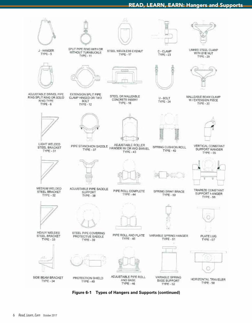
Figure 6-1 Types of Hangers and Supports (continued)
6 Read, Learn, Earn October 2017
READ, LEARN, EARN: Hangers and Supports
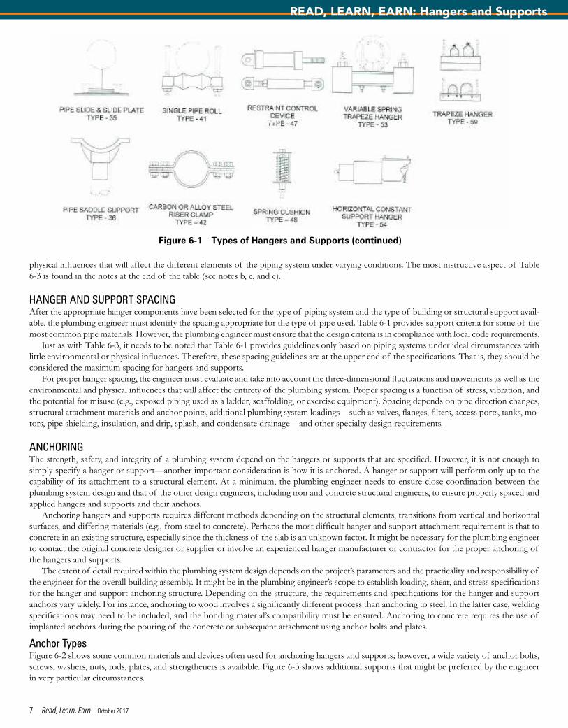
physical influences that will affect the different elements of the piping system under varying conditions. The most instructive aspect of Table 6-3 is found in the notes at the end of the table (see notes b, c, and e).
HANGER AND SUPPORT SPACINGAfter the appropriate hanger components have been selected for the type of piping system and the type of building or structural support avail-able, the plumbing engineer must identify the spacing appropriate for the type of pipe used. Table 6-1 provides support criteria for some of the most common pipe materials. However, the plumbing engineer must ensure that the design criteria is in compliance with local code requirements.
Just as with Table 6-3, it needs to be noted that Table 6-1 provides guidelines only based on piping systems under ideal circumstances with little environmental or physical influences. Therefore, these spacing guidelines are at the upper end of the specifications. That is, they should be considered the maximum spacing for hangers and supports.
For proper hanger spacing, the engineer must evaluate and take into account the three-dimensional fluctuations and movements as well as the environmental and physical influences that will affect the entirety of the plumbing system. Proper spacing is a function of stress, vibration, and the potential for misuse (e.g., exposed piping used as a ladder, scaffolding, or exercise equipment). Spacing depends on pipe direction changes, structural attachment materials and anchor points, additional plumbing system loadings—such as valves, flanges, filters, access ports, tanks, mo-tors, pipe shielding, insulation, and drip, splash, and condensate drainage—and other specialty design requirements.
ANCHORINGThe strength, safety, and integrity of a plumbing system depend on the hangers or supports that are specified. However, it is not enough to simply specify a hanger or support—another important consideration is how it is anchored. A hanger or support will perform only up to the capability of its attachment to a structural element. At a minimum, the plumbing engineer needs to ensure close coordination between the plumbing system design and that of the other design engineers, including iron and concrete structural engineers, to ensure properly spaced and applied hangers and supports and their anchors.
Anchoring hangers and supports requires different methods depending on the structural elements, transitions from vertical and horizontal surfaces, and differing materials (e.g., from steel to concrete). Perhaps the most difficult hanger and support attachment requirement is that to concrete in an existing structure, especially since the thickness of the slab is an unknown factor. It might be necessary for the plumbing engineer to contact the original concrete designer or supplier or involve an experienced hanger manufacturer or contractor for the proper anchoring of the hangers and supports.
The extent of detail required within the plumbing system design depends on the project’s parameters and the practicality and responsibility of the engineer for the overall building assembly. It might be in the plumbing engineer’s scope to establish loading, shear, and stress specifications for the hanger and support anchoring structure. Depending on the structure, the requirements and specifications for the hanger and support anchors vary widely. For instance, anchoring to wood involves a significantly different process than anchoring to steel. In the latter case, welding specifications may need to be included, and the bonding material’s compatibility must be ensured. Anchoring to concrete requires the use of implanted anchors during the pouring of the concrete or subsequent attachment using anchor bolts and plates.
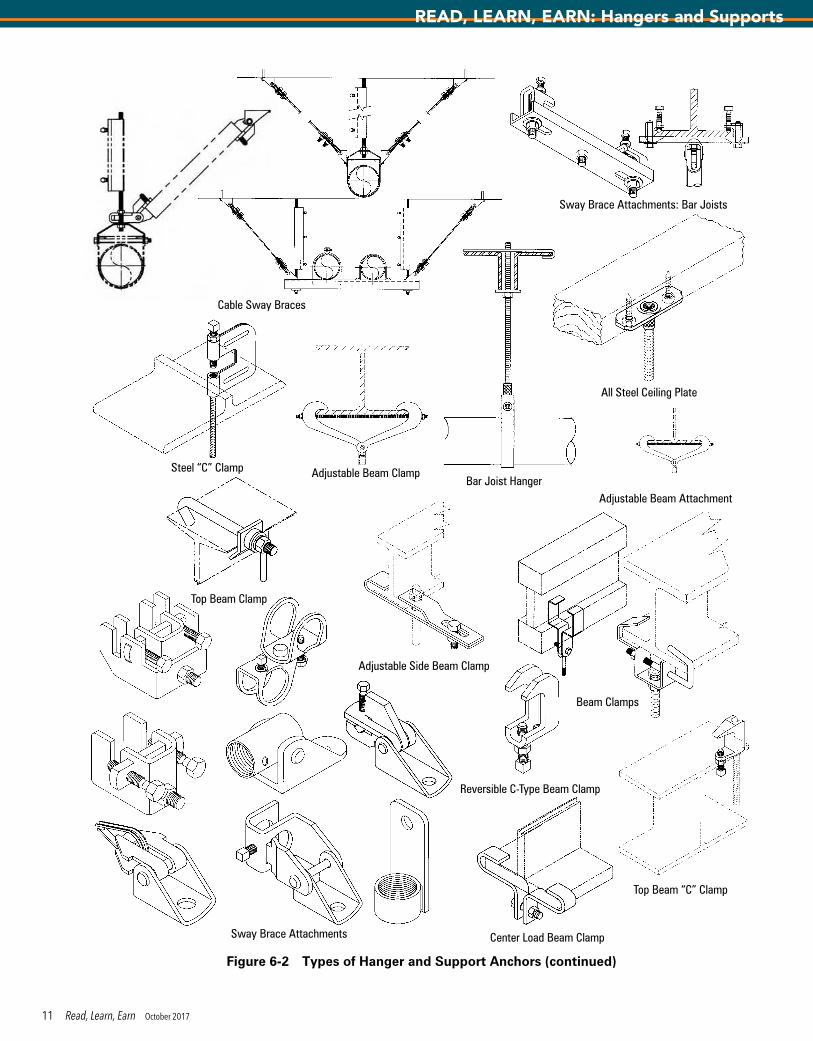
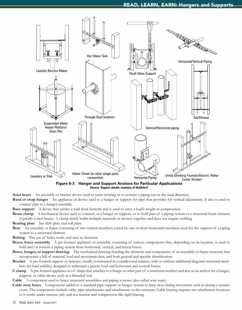
Anchor TypesFigure 6-2 shows some common materials and devices often used for anchoring hangers and supports; however, a wide variety of anchor bolts, screws, washers, nuts, rods, plates, and strengtheners is available. Figure 6-3 shows additional supports that might be preferred by the engineer in very particular circumstances.
Figure 6-1 Types of Hangers and Supports (continued)
7 Read, Learn, Earn October 2017
READ, LEARN, EARN: Hangers and Supports
Tab
le 6
-3
Han
ger
and
Sup
po
rt S
elec
tio
ns
Sys
tem
Ho
rizo
nta
l Pip
e A
ttac
hm
ents
Ver
tica
l Pip
e A
ttac
hm
ents
Han
ger
Ro
d
Fixt
ure
s, S
teel
o
r M
alle
able
Ir
on
Bu
ildin
g S
tru
ctu
re
Att
ach
men
ts, S
teel
an
d/o
r M
alle
able
Iro
n
Temperature Range, °F (°C)
Insulation
Steel ClipsA
Malleable Iron Rings
B
Steel BandsC
Steel ClampsD
Cast Iron Hanging Rolls
E
Cast IronF
Steel TrapezesG
Steel Protection Saddles and
ShieldsH
Steel or Cast Iron Stanchions
I
Steel Welded Attachments
J
Riser Clamps2 bolt
K
Steel Riser Clamps, 4 bolt
L
Steel Welded Attachments
M
Turn BucklesN
Swing EyesO
ClevisesP
InsertsQ
C-ClampsR
Beam ClampsS
Welded Attachments
T
BracketsU
HOT
A-1
COV-
ERED
a
24 W
/ 39
NON
E1,
5, 7
, 9,
10 W
/ 39
OR 4
02,
341
, 43
W/ 3
9 OR
40
44, 4
5,
46 W
/ 39
OR 4
0
59 W
/ 39
OR
4039
, 40
36, 3
7,
38 W
/ 39
OR 4
035
c8
42c
c13
, 15
16, 1
714
18e
19,
2320
, 21,
25
, 27
22, 5
7,
58c
31, 3
2,
33, 3
412
0 (4
9)
to 4
50
(232
)BA
RE24
, 26
6, 1
1, 1
21,
5, 7
, 9,
10
3, 4
41, 4
344
, 45,
46
59N
ONE
36, 3
7,
38
HOT
A-2
34CO
V-ER
EDa
24 W
/ 39
NON
E1
W/ 3
9 OR
40
341
W/ 3
9 OR
40
44, 4
5,
46 W
/ 39
OR 4
0
59 W
/ 39
OR
4039
, 40
36, 3
7,
38 W
/ 39
OR 4
035
cN
ONE
42c
c13
, 15
16, 1
714
18e
NON
E
20, 2
1,
25, 2
7,
28, 2
9,
30
22, 5
7,
58c
31, 3
2,
3345
1 (2
33)
to 7
50
(399
)BA
REN
ONE
NON
EN
ONE
3, 4
NON
EN
ONE
cN
ONE
NON
E
HOT
A-3
34CO
V-ER
EDa
NON
EN
ONE
1 W
/ 40
ALLO
Y 2,
3
41, 4
3 W
/ 40
OR
ALLO
Y 39
44, 4
5,
46 W
/ 40
OR A
L-LO
Y 39
59 W
/ 40
OR
ALLO
Y 39
40 A
LLOY
39
36, 3
7,
38 W
/ 40
OR A
LLOY
39
ALLO
Y 35
cN
ONE
ALLO
Y 42
c
ALLO
Y 39
c13
1714
c, e
NON
E
20, 2
1,
25, 2
7,
28, 2
9,
30
22, 5
7,
58c
31, 3
2,
33,
OVER
750
(3
99)
BARE
NON
EN
ONE
NON
EAL
LOY
2, 3
, 4N
ONE
NON
Ec
NON
EN
ONE
AMBI
ENT
BCO
V-ER
EDa
24, 2
6N
ONE
1, 5
, 7, 9
, 10
W/ 3
9 OR
40
3, 4
41, 4
3 W
/ 39
OR
40
44, 4
5,
46 W
/ 39
OR 4
0
59 W
/ 39
OR
4039
, 40
36, 3
7,
38 W
/ 39
OR 4
035
c8
42c
c13
, 15
16, 1
714
18e
19,
23
20, 2
1,
25, 2
7,
28, 2
9,
30
22, 5
7,
58c
31, 3
2,
33, 3
460
(16)
to
119
(48)
BARE
24, 2
66,
11,
12
1, 5
.7.9
, 10
3, 4
41, 4
344
, 45,
46
59N
ONE
36, 3
7,
38
COLD
C-1
34
COV-
ERED
a26
W/4
0N
ONE
1, 5
, 7, 9
, 10
W/4
03,
4
W/4
041
, 43
W/4
0d
44,
45, 4
6 W
/40d
59
W/4
040
36, 3
7,
38 W
/40
c8
42c
c13
, 15
16, 1
714
18e
19,
23
20, 2
1,
25, 2
7 28
, 29,
30
22, 5
7,
58c
31, 3
2,
3333
(1) t
o 59
(15)
BARE
24, 2
66,
11,
12
1, 5
, 7,
9, 1
03,
441
, 43
44, 4
5,
46c
NON
E36
, 37,
38
COLD
C-2
COV-
ERED
aN
ONE
NON
E1,
5, 7
, 9,
10 W
/ 40
NON
E41
, 43
W/ 4
0d
44, 4
5,
46 W
/ 40
d
c, d
W
/ 40
4036
, 37,
38
W/ 4
0c
842
c13
,15
16, 1
714
18e
19,
23
20, 2
1,
25, 2
7,
28, 2
9,
30
22, 5
7,
58c
31, 3
2,
33, 3
4–1
9(–2
8)
to 3
2 (0
)BA
REN
ONE
NON
E1,
5, 7
, 9.
103,
441
, 43
44, 4
5,
46c
NON
E36
, 37,
38
COLD
C-3
an
d C4
COV-
ERED
aN
ONE
NON
E1,
5, 7
, 9.
10 W
/ 40
NON
E41
, 43
W/ 4
0d
44, 4
5,
46 W
/ 40
d
b, c
, d
W/ 4
040
36, 3
7,
38 W
/ 40
b, c
b, c
b, c
b, c
13,
1516
, 17
1418
e19
, 23
20, 2
1,
25, 2
7,
28, 2
9,
30
22, 5
7,
58c
31, 3
2,
33, 3
4BE
LOW
–1
9 (–
28)
BARE
NON
EN
ONE
b, c
b, c
NON
EN
ONE
b, c
NON
Eb,
c
To fi
nd re
com
men
ded
hang
er o
r sup
port
com
pone
nts,
1. L
ocat
e th
e sy
stem
tem
pera
ture
and
insu
latio
n co
nditi
on in
the
two
colu
mns
at l
eft.
2. R
ead
acro
ss th
e co
lum
n he
adin
gs fo
r the
type
of c
ompo
nent
to b
e us
ed. 3
. Num
bers
in b
oxes
refe
r to
thos
e ty
pes
show
n in
Fig
ure
6-1.
a Han
gers
on
insu
late
d sy
stem
s sh
all i
ncor
pora
te p
rote
ctio
n sa
ddle
s, s
hiel
ds, p
ipe
clam
ps, o
r wel
ded
lugs
whi
ch p
roje
ct th
roug
h th
e in
sula
tion
to p
rovi
de e
xter
nal a
ttach
men
t. b T
he s
elec
tion
of ty
pe a
nd m
ater
ial s
hall
be m
ade
by th
e pi
ping
des
ign
engi
neer
.c T
he d
esig
n sh
all b
e in
acc
orda
nce
with
MSS
SP-
58 o
r as
spec
ified
by
the
pipi
ng d
esig
n en
gine
er.
d For
shi
elds
use
d w
ith ro
llers
or s
ubje
ct to
poi
nt lo
adin
g, s
ee M
SS S
P-58
Tab
le A
3.e C
ontin
uous
inse
rts, e
mbe
dded
pla
tes,
anc
hor b
olts
, and
con
cret
e fa
sten
ers
may
be
used
as
spec
ified
by
the
pipi
ng d
esig
n en
gine
er.
f The
nee
d to
mai
ntai
n a
vapo
r bar
rier m
ay b
e re
quire
d be
caus
e of
am
bien
t dew
poin
t con
side
ratio
ns.
Extra
cted
from
AN
SI/M
SS S
P-58
-200
9 w
ith p
erm
issi
on o
f the
pub
lishe
r, M
anuf
actu
rers
Sta
ndar
diza
tion
Soci
ety
of th
e Va
lve
and
Fitti
ngs
Indu
stry
Inc.
8 Read, Learn, Earn October 2017
READ, LEARN, EARN: Hangers and Supports
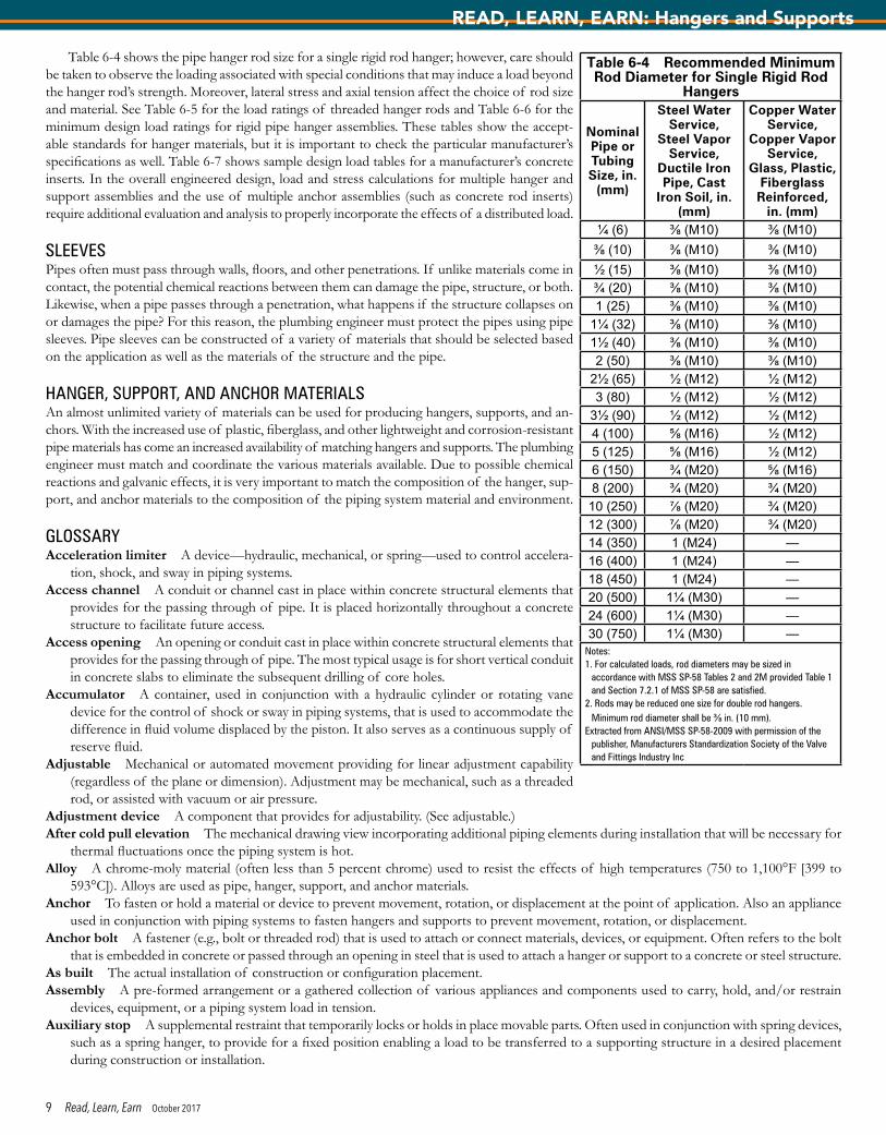
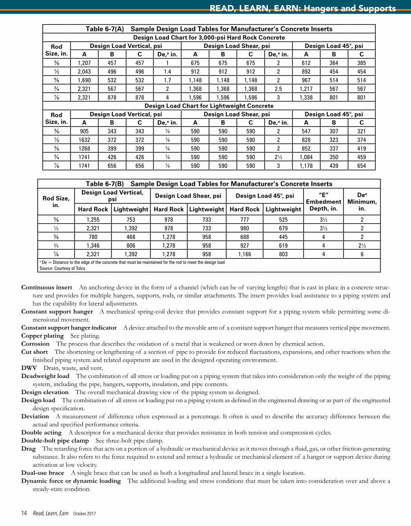
Table 6-4 shows the pipe hanger rod size for a single rigid rod hanger; however, care should be taken to observe the loading associated with special conditions that may induce a load beyond the hanger rod’s strength. Moreover, lateral stress and axial tension affect the choice of rod size and material. See Table 6-5 for the load ratings of threaded hanger rods and Table 6-6 for the minimum design load ratings for rigid pipe hanger assemblies. These tables show the accept-able standards for hanger materials, but it is important to check the particular manufacturer’s specifications as well. Table 6-7 shows sample design load tables for a manufacturer’s concrete inserts. In the overall engineered design, load and stress calculations for multiple hanger and support assemblies and the use of multiple anchor assemblies (such as concrete rod inserts) require additional evaluation and analysis to properly incorporate the effects of a distributed load.
SLEEVESPipes often must pass through walls, floors, and other penetrations. If unlike materials come in contact, the potential chemical reactions between them can damage the pipe, structure, or both. Likewise, when a pipe passes through a penetration, what happens if the structure collapses on or damages the pipe? For this reason, the plumbing engineer must protect the pipes using pipe sleeves. Pipe sleeves can be constructed of a variety of materials that should be selected based on the application as well as the materials of the structure and the pipe.
HANGER, SUPPORT, AND ANCHOR MATERIALSAn almost unlimited variety of materials can be used for producing hangers, supports, and an-chors. With the increased use of plastic, fiberglass, and other lightweight and corrosion-resistant pipe materials has come an increased availability of matching hangers and supports. The plumbing engineer must match and coordinate the various materials available. Due to possible chemical reactions and galvanic effects, it is very important to match the composition of the hanger, sup-port, and anchor materials to the composition of the piping system material and environment.
GLOSSARYAcceleration limiter A device—hydraulic, mechanical, or spring—used to control accelera-
tion, shock, and sway in piping systems.Access channel A conduit or channel cast in place within concrete structural elements that
provides for the passing through of pipe. It is placed horizontally throughout a concrete structure to facilitate future access.
Access opening An opening or conduit cast in place within concrete structural elements that provides for the passing through of pipe. The most typical usage is for short vertical conduit in concrete slabs to eliminate the subsequent drilling of core holes.
Accumulator A container, used in conjunction with a hydraulic cylinder or rotating vane device for the control of shock or sway in piping systems, that is used to accommodate the difference in fluid volume displaced by the piston. It also serves as a continuous supply of reserve fluid.
Adjustable Mechanical or automated movement providing for linear adjustment capability (regardless of the plane or dimension). Adjustment may be mechanical, such as a threaded rod, or assisted with vacuum or air pressure.
Adjustment device A component that provides for adjustability. (See adjustable.)After cold pull elevation The mechanical drawing view incorporating additional piping elements during installation that will be necessary for
thermal fluctuations once the piping system is hot.Alloy A chrome-moly material (often less than 5 percent chrome) used to resist the effects of high temperatures (750 to 1,100°F [399 to
593°C]). Alloys are used as pipe, hanger, support, and anchor materials.Anchor To fasten or hold a material or device to prevent movement, rotation, or displacement at the point of application. Also an appliance
used in conjunction with piping systems to fasten hangers and supports to prevent movement, rotation, or displacement.Anchor bolt A fastener (e.g., bolt or threaded rod) that is used to attach or connect materials, devices, or equipment. Often refers to the bolt
that is embedded in concrete or passed through an opening in steel that is used to attach a hanger or support to a concrete or steel structure.As built The actual installation of construction or configuration placement.Assembly A pre-formed arrangement or a gathered collection of various appliances and components used to carry, hold, and/or restrain
devices, equipment, or a piping system load in tension.Auxiliary stop A supplemental restraint that temporarily locks or holds in place movable parts. Often used in conjunction with spring devices,
such as a spring hanger, to provide for a fixed position enabling a load to be transferred to a supporting structure in a desired placement during construction or installation.
Table 6-4 Recommended Minimum Rod Diameter for Single Rigid Rod
Hangers
Nominal Pipe or Tubing Size, in.
(mm)
Steel Water Service,
Steel Vapor Service,
Ductile Iron Pipe, Cast
Iron Soil, in. (mm)
Copper Water Service,
Copper Vapor Service,
Glass, Plastic, Fiberglass Reinforced,
in. (mm)¼ (6) ⅜ (M10) ⅜ (M10)⅜ (10) ⅜ (M10) ⅜ (M10)½ (15) ⅜ (M10) ⅜ (M10)¾ (20) ⅜ (M10) ⅜ (M10)1 (25) ⅜ (M10) ⅜ (M10)
1¼ (32) ⅜ (M10) ⅜ (M10)1½ (40) ⅜ (M10) ⅜ (M10)2 (50) ⅜ (M10) ⅜ (M10)
2½ (65) ½ (M12) ½ (M12)3 (80) ½ (M12) ½ (M12)
3½ (90) ½ (M12) ½ (M12)4 (100) ⅝ (M16) ½ (M12)5 (125) ⅝ (M16) ½ (M12)6 (150) ¾ (M20) ⅝ (M16)8 (200) ¾ (M20) ¾ (M20)10 (250) ⅞ (M20) ¾ (M20)12 (300) ⅞ (M20) ¾ (M20)14 (350) 1 (M24) —16 (400) 1 (M24) —18 (450) 1 (M24) —20 (500) 1¼ (M30) —24 (600) 1¼ (M30) —30 (750) 1¼ (M30) —
Notes:1. For calculated loads, rod diameters may be sized in
accordance with MSS SP-58 Tables 2 and 2M provided Table 1 and Section 7.2.1 of MSS SP-58 are satisfied.
2. Rods may be reduced one size for double rod hangers. Minimum rod diameter shall be ⅜ in. (10 mm).
Extracted from ANSI/MSS SP-58-2009 with permission of the publisher, Manufacturers Standardization Society of the Valve and Fittings Industry Inc
9 Read, Learn, Earn October 2017
READ, LEARN, EARN: Hangers and Supports
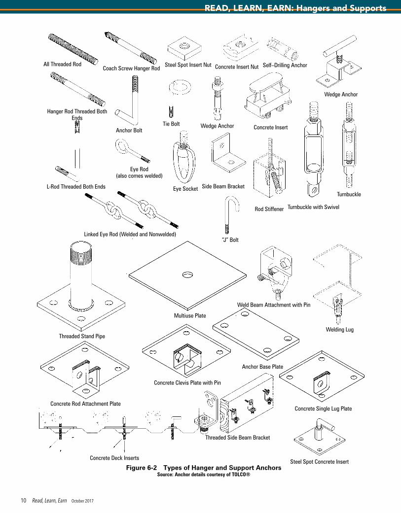
Steel Spot Concrete InsertFigure 6-2 Types of Hanger and Support Anchors
Source: Anchor details courtesy of TOLCO®
Eye Socket
Turnbuckle with Swivel
Steel Spot Insert Nut Concrete Insert Nut
Concrete Insert
Self–Drilling Anchor
Wedge Anchor
Turnbuckle
Anchor Bolt
L-Rod Threaded Both Ends
Coach Screw Hanger Rod
Hanger Rod Threaded Both Ends
Tie Bolt
“J” Bolt
All Threaded Rod
Linked Eye Rod (Welded and Nonwelded)
Wedge Anchor
Eye Rod (also comes welded)
Rod Stiffener
Side Beam Bracket
Threaded Stand Pipe
Multiuse Plate
Anchor Base Plate
Concrete Deck Inserts
Threaded Side Beam Bracket
Concrete Rod Attachment Plate
Concrete Clevis Plate with Pin
Concrete Single Lug Plate
Welding Lug
Weld Beam Attachment with Pin
10 Read, Learn, Earn October 2017
READ, LEARN, EARN: Hangers and Supports
All Steel Ceiling Plate
Top Beam “C” Clamp
Reversible C-Type Beam Clamp
Steel “C” Clamp
Top Beam Clamp
Bar Joist Hanger
Center Load Beam Clamp
Adjustable Beam Attachment
Adjustable Side Beam Clamp
Adjustable Beam Clamp
Beam Clamps
Cable Sway Braces
Sway Brace Attachments
Sway Brace Attachments: Bar Joists
Figure 6-2 Types of Hanger and Support Anchors (continued)
11 Read, Learn, Earn October 2017
READ, LEARN, EARN: Hangers and Supports
Axial brace An assembly or bracket device used to resist twisting or to restrain a piping run in the axial direction.Band or strap hanger An appliance or device used as a hanger or support for pipe that provides for vertical adjustment. It also is used to
connect pipe to a hanger assembly.Base support A device that carries a load from beneath and is used to carry a load’s weight in compression.Beam clamp A mechanical device used to connect, as a hanger or support, or to hold part of a piping system to a structural beam element
(typically a steel beam). A clamp firmly holds multiple materials or devices together and does not require welding.Bearing plate See slide plate and roll plate.Bent An assembly or frame consisting of two vertical members joined by one or more horizontal members used for the support of a piping
system to a structural element.Bolting The use of bolts, studs, and nuts as fasteners.Brace, brace assembly A pre-formed appliance or assembly consisting of various components that, depending on its location, is used to
hold and/or restrain a piping system from horizontal, vertical, and lateral forces.Brace, hanger, or support drawing The mechanical drawing detailing the elements and components of an assembly or frame structure that
incorporates a bill of material, load and movement data, and both general and specific identification.Bracket A pre-formed support or fastener, usually constructed in a cantilevered manner, with or without additional diagonal structural mem-
bers for load stability, designed to withstand a gravity load and horizontal and vertical forces.C clamp A pre-formed appliance in a C shape that attaches to a flange or other part of a structural member and acts as an anchor for a hanger,
support, or other device such as a threaded rod.Cable A component used to brace structural assemblies and piping systems (also called wire rope).Cable sway brace Components added to a standard pipe support or hanger system to limit sway during movement such as during a seismic
event. The components include cable, pipe attachments, and attachments to the structure. Cable bracing requires two attachment locations as it works under tension only and not tension and compression like rigid bracing.
Figure 6-3 Hanger and Support Anchors for Particular ApplicationsSource: Support details courtesy of Holdrite®
Hot Water Tank
Laundry Box/Ice Maker
Horizontal/Vertical Piping
Flush Valve Support
Tub/Shower
Vertical/Horizontal piping
Through Stud Isolation
Suspended Water Heater Platform/
Drain Pan
Lavatory or SinkWater Closet (or other single point
connection) Horizontal PipingUrinal (Drinking Fountain/Electric Water
Cooler Similar)
12 Read, Learn, Earn October 2017
READ, LEARN, EARN: Hangers and Supports

Cantilever A projecting structural element or member sup-ported at only one end.
Center beam clamp A jaw-type mechanical device used to connect, as a hanger or support, or used to hold part of a piping system to a structural beam element (typically a steel beam). It is used with I beams and wide flange beams to provide a centered beam connection.
Channel clamp A mechanical device with a channel adapter and hook rod that provides an off-center attachment to the bottom flange of a channel beam for a hanger, support, or other part of a piping system.
Clamp A mechanical device used to connect, as a hanger or support, or hold part of a piping system to a structural beam element. (A clamp firmly holds multiple materials or devices together and does not require welding.) See beam clamp, C clamp, channel clamp, double bolt pipe, three-bolt clamp, double-bolt riser, riser clamp, and pipe clamp.
Clevis A connector device or metal shackle with drilled ends to receive a pin or bolt that is used for attaching or sus-pending parts.
Clevis hanger A support device providing vertical adjust-ment consisting of a clevis-type top bolted to a formed steel bottom strap.
Cold elevation See design elevation and after cold pull eleva-tion.
Cold hanger location The location of the pipe hangers, supports, and assemblies of the installed piping system in reference to the building’s structure and structural elements prior to the invoking of an operating environment.
Cold load The stress or loading put on a piping system prior to the occurrence of a normal or steady-state operating en-vironment (as measured at ambient temperature). The cold load equals the operating load plus or minus load variations.
Cold setting The position at which a mechanical control device indicator, such as that on a spring hanger, is set to denote the proper nonoperating position installation setting of the unit.
Cold shoe A T-section hanger or support with integrated in-sulation that has been designed for cold temperature piping system applications.
Cold spring The act of pre-stressing a piping system during installation to condition it for minimal fluctuations, expan-sions, and other reactions when the finished piping system and related equipment are used in the designed operating environment.
Colored finish A generic term to describe various color finishes that are used as an identifier for product compatibility. For example, a copper-colored finish on connectors or piping denotes that the product was sized for copper tubing.
Commercial piping system A piping system located in a commercial building structure that generally includes fire protection, plumbing, heating, and cooling piping systems.
Component Any individual item, appliance, or device that is combined with others to create an assembly or is part of a whole.
Concrete fastener A device installed in or attached to concrete by various means (often precast, drilled, or epoxied) to which a pipe hanger or support can be attached.
Concrete insert, concrete insert box An anchor device cast in place in concrete that provides for a hanger, support, rod, or similar attachment. The insert provides load assistance to a piping system and has nominal lateral adjustment.
Table 6-5 Load Ratings of Carbon Steel Threaded Hanger
Rods
Nominal Rod
Diameter, in. (mm)
Root Area of Thread, in.2 (mm2)
Maximum Safe Load at Rod Temp.
of 650°F (343°C), lb
(kg)⅜ (9.6) 0.068 (43.8) 730 (3.23)½ (12.7) 0.126 (81.3) 1,350 (5.98)⅝ (15.8) 0.202 (130.3) 2,160 (9.61)¾ (19.0) 0.302 (194.8) 3,230 (14.4)⅞ (22.2) 0.419 (270.3) 4,480 (19.9)1 (25.4) 0.551 (356.1) 5,900 (26.2)
1¼ (31.8) 0.890 (573.5) 9,500 (42.4)1½ (38.1) 1.29 (834.2) 13,800 (61.6)1¾ (44.4) 1.74 (1,125) 18,600 (82.8)2 (50.8) 2.30 (1,479) 24,600 (109)
2¼ (57.2) 3.02 (1,949) 32,300 (144)2½ (63.5) 3.72 (2,397) 39,800 (177)2¾ (69.8) 4.62 (2,980) 49,400 (220)3 (76.2) 5.62 (3,626) 60,100 (267)
3¼ (82.6) 6.72 (4,435) 71,900 (320)3½ (88.9) 7.92 (5,108) 84,700 (377)3¾ (95.2) 9.21 (5,945) 98,500 (438)4 (101.6) 10.6 (6,844) 114,000 (505)
4¼ (108.0) 12.1 (7,806) 129,000 (576)4½ (114.3) 13.7 (8,832) 146,000 (652)4¾ (120.6) 15.4 (9,922) 165,000 (733)5 (127.0) 17.2 (11,074) 184,000 (819)
Notes:1. For materials other than carbon steel, see requirements
of ANSI/MSS SP-58-2009, Section 4.8 and Table A2.2. Tabulated loads are based on a minimum actual tensile
stress of 50 ksi (345 MPa) divided by a safety factor of 3.5, reduced by 25%, resulting in an allowable stress of 10.7 ksi. (The 25% reduction is to allow for normal installation and service conditions.)
3. Root areas of thread are based on the following thread series: diam. 4 in. and below: coarse thread (UNC); diam. above 4 in.: 4 thread (4-UN).
Extracted from ANSI/MSS SP-58-2009 with permission of the publisher, Manufacturers Standardization Society of the Valve and Fittings Industry Inc
Table 6-6 Minimum Design Load Ratings for
Pipe Hanger Assemblies*
Nominal Pipe or
Tube Size, in. (mm)
Minimum Design Load
Rating at Normal Temp. Range, lb (kg)
⅜ (10) 150 (0.67)½ (15) 150 (0.67)¾ (20) 150 (0.67)1 (25) 150 (0.67)
1¼ (32) 150 (0.67)1½ (40) 150 (0.67)2 (50) 150 (0.67)
2½ (65) 150 (0.67)3 (80) 200 (0.89)
3½ (90) 210 (0.93)4 (100) 250 (1.11)5 (125) 360 (1.60)6 (150) 480 (2.14)8 (200) 760 (3.38)10 (250) 1,120 (4.98)12 (300) 1,480 (6.58)14 (350) 1,710 (7.61)16 (400) 2,130 (9.47)18 (450) 2,580 (11.48)20 (500) 3,060 (13.61)24 (600) 3,060 (13.61)30 (750) 3,500 (15.57)
* Applicable to all components of complete assembly, including pipe attachment, rod, fixtures, and building attachment
Notes:1. See MSS SP-58-2009 Section 4 for
allowable stresses and temperatures.2. Normal temperature range is –20 to
650°F (–29 to 343°C) for carbon steel, –20 to 450°F (–29 to 231°C) for malleable iron, and –20 to 400°F (–29 to 204°C) for gray iron.
3. See MSS SP-58-2009 Section 7.2.1 for minimum rod diameter restrictions.
4. For loads greater than those tabulated, hanger component load ratings shall be established by the manufacturer. Design shall be in accordance with all criteria as outlined in MSS SP-58-2009.
5. Pipe attachment ratings for temperature ranges between 650 and 750°F (343 and 398°C) shall be reduced by the ratio of allowable stress at service temperature to the allowable stresses at 650°F (343°C).
6. For services over 750°F (398°C), attachments in direct contact with the pipe shall be designed to allowable stresses listed in MSS SP-58-2009, Tables A2 and A2M.
Extracted from ANSI/MSS SP-58-2009 with permission of the publisher, Manufacturers Standardization Society of the Valve and Fittings Industry Inc.
13 Read, Learn, Earn October 2017
READ, LEARN, EARN: Hangers and Supports
Continuous insert An anchoring device in the form of a channel (which can be of varying lengths) that is cast in place in a concrete struc-ture and provides for multiple hangers, supports, rods, or similar attachments. The insert provides load assistance to a piping system and has the capability for lateral adjustments.
Constant support hanger A mechanical spring-coil device that provides constant support for a piping system while permitting some di-mensional movement.
Constant support hanger indicator A device attached to the movable arm of a constant support hanger that measures vertical pipe movement.Copper plating See plating.Corrosion The process that describes the oxidation of a metal that is weakened or worn down by chemical action.Cut short The shortening or lengthening of a section of pipe to provide for reduced fluctuations, expansions, and other reactions when the
finished piping system and related equipment are used in the designed operating environment.DWV Drain, waste, and vent.Deadweight load The combination of all stress or loading put on a piping system that takes into consideration only the weight of the piping
system, including the pipe, hangers, supports, insulation, and pipe contents.Design elevation The overall mechanical drawing view of the piping system as designed.Design load The combination of all stress or loading put on a piping system as defined in the engineered drawing or as part of the engineered
design specification.Deviation A measurement of difference often expressed as a percentage. It often is used to describe the accuracy difference between the
actual and specified performance criteria.Double acting A descriptor for a mechanical device that provides resistance in both tension and compression cycles.Double-bolt pipe clamp See three-bolt pipe clamp.Drag The retarding force that acts on a portion of a hydraulic or mechanical device as it moves through a fluid, gas, or other friction-generating
substance. It also refers to the force required to extend and retract a hydraulic or mechanical element of a hanger or support device during activation at low velocity.
Dual-use brace A single brace that can be used as both a longitudinal and lateral brace in a single location.Dynamic force or dynamic loading The additional loading and stress conditions that must be taken into consideration over and above a
steady-state condition.
Table 6-7(A) Sample Design Load Tables for Manufacturer’s Concrete InsertsDesign Load Chart for 3,000-psi Hard Rock Concrete
Rod Size, in.
Design Load Vertical, psi Design Load Shear, psi Design Load 45°, psiA B C De,a in. A B C De,a in. A B C
⅜ 1,207 457 457 1 675 675 675 2 612 364 385½ 2,043 496 496 1.4 912 912 912 2 892 454 454⅝ 1,690 532 532 1.7 1,148 1,148 1,148 2 967 514 514¾ 2,321 567 567 2 1,368 1,368 1,368 2.5 1,217 567 567⅞ 2,321 878 878 4 1,596 1,596 1,596 3 1,338 801 801
Design Load Chart for Lightweight Concrete
Rod Size, in.
Design Load Vertical, psi Design Load Shear, psi Design Load 45°, psiA B C De,a in. A B C De,a in. A B C
⅜ 905 343 343 ⅞ 590 590 590 2 547 307 321½ 1632 372 372 ⅞ 590 590 590 2 828 323 374⅜ 1268 399 399 ⅞ 590 590 590 2 852 337 419¾ 1741 426 426 ⅞ 590 590 590 2½ 1,084 350 459⅞ 1741 656 656 ⅞ 590 590 590 3 1,178 439 654
Table 6-7(B) Sample Design Load Tables for Manufacturer’s Concrete Inserts
Rod Size, in.
Design Load Vertical, psi Design Load Shear, psi Design Load 45°, psi “E”
Embedment Depth, in.
Dea Minimum,
in.Hard Rock Lightweight Hard Rock Lightweight Hard Rock Lightweight
⅜ 1,255 753 978 733 777 525 3½ 2½ 2,321 1,392 978 733 980 679 3½ 2⅜ 780 468 1,278 958 688 445 4 2¾ 1,346 806 1,278 958 927 619 4 2½⅞ 2,321 1,392 1,278 958 1,166 803 4 6
a De = Distance to the edge of the concrete that must be maintained for the rod to meet the design load Source: Courtesy of Tolco
14 Read, Learn, Earn October 2017
READ, LEARN, EARN: Hangers and Supports
Dynamic load The temporary stress or loading put on a piping system as the result of internal or external forces that create movement or motion in the system.
Elbow lug An elbow-shaped device with a pipe connector welded to it for use as an attachment.Electrogalvanized A protective coating of electroplated zinc. (See also galvanized.)Electroplated Plating by using an electrodeposition process. (See also plating.)Electrolysis The production of chemical changes due to differences in the electrical potential between dissimilar materials in the presence
of moisture. (See also corrosion.)Elevation A mechanical drawing view that is a geometrical projection as seen on a vertical plane.Embedded A device or fastener that is cast in place in a concrete structure.Engineered drawing A mechanical drawing that details the elements and components of a piping system and incorporates a bill of material,
load and movement data, location information, and both general and specific identification.Engineered hanger assembly A mechanical drawing that details the elements and components of a hanger assembly and incorporates a bill
of material, load and movement data, location information, and both general and specific identification. (See also semi-engineered hanger assembly.)
Erected elevation See design elevation.Extension riser clamp An attachment device for the support of vertical piping that provides for the transfer of the piping load to the bear-
ing surface to which the clamp is attached.Eye rod A bolt or rod with a circular or pear-shaped end that permits other components or devices to be attached by means of a bolt or pin.
The eye may be forged, welded, or non-welded.Eye socket An appliance that provides for the attachment of a threaded bolt or rod to the bolt or rod of another component or device.Fabrication A term used to refer to a part constructed or manufactured out of standard parts or raw materials.Fabricated steel part A component that is constructed from standard shapes of steel plate.Fabricator A business engaged in the fabrication of parts.Forged clevis A connector device, a clevis, that has been formed as one piece (i.e., forged).Four-way brace An assembly consisting of lateral and longitudinal bracing that is designed to control back-and-forth movement in four
directions.Framing steel A structural steel member, normally less than 10 feet in length, used between existing members as a means of providing for
the attachment of a hanger or support for a piping system.Friction load The stress or loading put on a piping system as the result of frictional forces that exist between different surfaces that are in
contact with each other, such as moving or sliding surfaces.Galvanized A zinc coating applied to steel to protect against oxidation and other chemical actions.Gang hanger A hanger assembly utilizing a common cross-member to provide support for parallel runs or banks of piping.Guide A device used to permit pipe movement in a predetermined direction while restraining movement in other directions.Hanger A device that is suspended from a structure and used to carry or support a load.Hanger assembly A general term used to describe a series of assembled components that make up a device that is connected to or suspended
from a structure and is used to carry or support a load in tension or carry a load under compression. The device may be designed to prevent, resist, or limit movement, or it may be used to permit movement in a predetermined direction while restraining movement in other directions.
Hanger drawing See brace, hanger, or support drawing.Hanger load See pipe hanger load.Hanger rod A round steel bar, normally threaded, used to connect components for hangers and supports.Heavy bracket A bracket used for the support of heavy loads. (See bracket.)Hinged pipe clamp Also known as a split ring, a hinged attachment device that permits installation before or after piping is in place and
used primarily on non-insulated piping.Horizontal traveler A hanger or support device that accommodates horizontal piping movement.Hot-dip galvanized A corrosion protection coating of zinc applied to steel or other metals.Hot elevation The mechanical drawing view of a piping system as it will appear in its full operating environment.Hot hanger location The location of the pipe hangers, supports, and assemblies of the installed piping system in reference to the building’s
structure and structural elements within the operating environment.Hot load The stress or loading put on a piping system as the result of a normal or steady-state operating environment. (See operating load.)Hot setting The position at which a mechanical control device indicator, such as that on a spring hanger, is set to denote the proper operat-
ing position setting of the unit.Hot shoe A T-section hanger or support with integrated insulation that has been designed for hot-temperature piping system applications.HVAC Heating, ventilation, and air-conditioning.Hydraulic snubber See hydraulic sway brace.Hydraulic sway brace A hydraulic cylinder or rotating vane device used to control shock or sway in piping systems, while allowing for normal
thermal expansion.Hydrostatic load The stress or loading put on a piping system as the result of hydrostatic testing. (See hydrostatic test load.)
15 Read, Learn, Earn October 2017
READ, LEARN, EARN: Hangers and Supports
Hydrostatic lock The condition wherein a supplemental restraint temporarily locks or holds in place moveable parts during a hydrostatic test. It often is used in conjunction with spring devices, such as a spring hanger, to provide for a fixed position and enabling a load to be transferred to a supporting structure in a desired placement during construction or installation.
Hydrostatic test A pre-operational test whereby the piping system is subjected to a pressurized fluid in excess of the specified operational pressure to ensure the integrity of the system.
Hydrostatic test load The temporary loading condition consisting of the total load weight of the piping (gravitational load), insulation, and test fluid for piping systems subjected to hydrostatic tests.
Industrial piping system A piping system located in an industrial complex that generally includes fire protection, plumbing, heating, and cooling piping systems and also incorporates process, vacuum, air, steam, or chemical piping systems.
Insert An anchor device that is cast in place in a concrete structure and provides for a hanger, support, rod, or similar attachment. Inserts provide load assistance to a piping system and have nominal lateral adjustment.
Insert box See concrete insert.Insert nut A female threaded anchor device that is locked into position as part of an insert and that receives a threaded rod or bolt.Institutional piping system A piping system located in an institutional environment or building structure that generally includes fire protec-
tion, plumbing, heating, and cooling piping systems, as well as process, vacuum, air, or chemical gas piping systems.Insulated pipe support A hanger or support with an integrated insulation insert designed for use with insulated pipe.Insulation protection saddle A device used to prevent damage to the insulation on a pipe at the support point.Integral attachment When connector pieces and devices have been welded together as hangers and supports or an assembly.Intermediate anchor An attachment point used to control the distribution, loading, and movement on a flexible piping system.Invert A drawing elevation view from the bottom or underneath.Jacket A metal covering placed around the insulation on a pipe to protect it against damage.Knee brace A diagonal structural member used to transfer load or provide stability.Lateral brace A brace designed to restrain a piping system against transverse loads.Lateral stability The state or degree of control of a piping system transverse to the run of the pipe.Light bracket A bracket used for the support of light loads. (See bracket.)Limit stop An internal device built into a mechanical device to prevent the overstressing of a spring coil, overtravel, or release of a load.Liner Material placed between hangers, supports, or an assembly to protect a piping system from damage or other undesirable effects.Load adjustment scale A scale used on a mechanical device to indicate the load adjustment.Load bolt or pin A bolt or pin used to support the weight or load carried by a hanger or assembly.Load coupling An adjustment device used to connect hanger and support components.Load indicator A pointer, dial, or gauge for reading or determining the settings and changes of a device.Load rated The rating of a particular size of component or assembly to withstand a specified force with a safety factor applied.Load scale A measurement pointer, dial, or gauge attached to a device to provide a means of determining the static or dynamic aspects of
a supported load.Load variation The difference in the elevations at a support point between the time of installation (cold) and actual operating (hot) environment.Load See pipe hanger load.Location See pipe hanger location.Lock up The operational period when a hydraulic, mechanical, or spring device used to control shock and sway in a piping system is actuated.Longitudinal brace A brace designed to restrain a piping system against axial loads.Lug A welded appliance to provide an attachment point to a structural member or piping.Mechanical snubber See mechanical sway brace.Mechanical sway brace A mechanical device used to control shock or sway in piping systems, while allowing for normal thermal expansion.Medium bracket A bracket used for the support of moderate loads. (See bracket.)Metric hanger A hanger or support that conforms to metric measurements and, where appropriate, contains a metric threaded connection.Mill galvanized A corrosion-protection coating of zinc applied at the point of fabrication.Multiple support See gang hanger.Negligible movement The calculated minimum movement at a support point for the portion of a piping system with inherent flexibility.Nominal size The identified size, which may vary from the actual size.Non-integral attachment When connector pieces and devices do not require being welded together as hangers and supports or an assembly.Offset A relative displacement between a structural attachment point and a piping system that is incorporated into the design to accommodate
movement.Operating load The stress or loading put on a piping system as the result of a normal or steady-state operating environment.OSHPD California Office of Statewide Health Planning and Development, which is a national leader in seismic restraint guidelines and
requirements.Pipe attachment Any component or device used to connect a pipe to a hanger, support, or assembly.Pipe brace See brace.Pipe channel A conduit or channel cast in place within concrete structural elements that provides for the passing through of pipe. It is placed
horizontally throughout a concrete structure to facilitate future access.Pipe clamp A bolted clamp attachment that connects a pipe to a hanger, support, assembly, or structural element.
16 Read, Learn, Earn October 2017
READ, LEARN, EARN: Hangers and Supports
Pipe clip An attachment appliance used to connect a pipe directly to a structural element. Also referred to as a strap or pipe clamp.Pipe covering protection saddle A protective covering used to prevent damage to insulation surrounding a pipe at hanger and support points.Pipe elevation See design elevation, erected elevation, after cold pull elevation, and cold elevation.Pipe hanger An appliance or device attached to or suspended from a structural element that is used to support a piping system load in tension.Pipe hanger assembly An assembly of hangers used to hold a piping system.Pipe hanger drawing A mechanical drawing that details the elements and components of a piping system and incorporates a bill of material,
load and movement data, location information, and both general and specific identification. (See also engineered drawing and semi-engineered drawing.)
Pipe hanger load See specific load types: cold load, deadweight load, design load, dynamic load, friction load, hot load, hydrostatic load, operating load, seismic load, thermal load, thrust load, trip-out load, water hammer load, and wind load.
Pipe hanger location See location types: cold hanger location and hot hanger location.Pipe hanger plan and pipe hanger plan location The engineered design and elevations that fully detail the hangers, supports, and anchors
of a piping system. Mechanical drawings include appropriate offsets as a result of movement and displacement expectations.Pipe insulation shield A rigid insert appliance designed to protect pipe insulation passing through hangers, supports, and assemblies.Pipe load See specific load types: cold load, deadweight load, design load, dynamic load, friction load, hot load, hydrostatic load, operating
load, seismic load, thermal load, thrust load, trip-out load, water hammer load, and wind load.Pipe opening An opening, conduit, or channel cast in place within a concrete structural element that provides for the passing through of
pipe. The most typical usage is for short vertical conduit in concrete slabs to eliminate the subsequent drilling of core holes.Pipe rack A structural frame that is used to support piping systems. (See assembly.)Pipe roll A pipe hanger or support that utilizes a roller or bearing device to provide the ability for lateral axial movement in a piping system.Pipe saddle support A pipe support that utilizes a curved section to cradle the pipe.Pipe shoe A hanger or support (typically T-shaped) attached to a pipe to transmit the load or forces to adjacent structural elements.Pipe size Nominal pipe size, unless otherwise specified.Pipe sleeve An opening, conduit, or channel cast in place within a concrete structural element that provides for the passing through of pipe.
The most typical usage is for short vertical conduit in concrete slabs to eliminate the subsequent drilling of core holes. However, conduit or channel may be placed horizontally throughout a concrete structure to facilitate future access.
Pipe sleeve, pipe sleeve hanger or support An appliance or device that surrounds a pipe and connects to a hanger or support to provide for alignment and limited movement.
Pipe slide A hanger or support that incorporates a slide plate to accommodate horizontal pipe movement.Pipe strap An attachment appliance used to connect a pipe directly to a structural element. (See pipe clip and pipe clamp.)Pipe support A device or stanchion by which a pipe is carried or supported from beneath. In this position, the pipe load is in compression.Pipe system load See specific load types: cold load, deadweight load, design load, dynamic load, friction load, hot load, hydrostatic load,
operating load, seismic load, thermal load, thrust load, trip-out load, water hammer load, and wind load.Plate lug See lug.Plating An electroplating process whereby a metallic coating (e.g., copper, chrome, or zinc) is deposited on a substrate.Point loading The point of application of a load between two surfaces. It typically describes the load point between a curved and a flat surface.Preset Prior installation adjustment of hangers, supports assemblies, equipment, and devices.Protection saddle A saddle that provides a protective covering or coating to prevent damage to pipe or to the insulation surrounding a pipe
at hanger and support points.Protection shield An appliance, which may be rigid or flexible, designed to protect pipe or insulation at contact points with hangers and supports.Random hanger A hanger or support that requires field fabrication, the exact location, shape, and type of which are left to the discretion
of the installer.Reservoir An attachment or separate container used in conjunction with a fluid- (or gas-) using device (e.g., hydraulic) that provides a means to
store or hold a supply of liquid (or gas) to provide for a reserve or otherwise ensure for an adequate or continuous supply of fluid (or gas).Restraint An appliance, device, or equipment that prevents, resists, or limits unplanned or random movement.Restraining control device A hydraulic, mechanical, spring, or other rigid or flexible hanger, support, or device used to control movement.Resilient support A hanger, support, or device that provides for vertical, horizontal, lateral, or axial movement.Retaining strap An appliance or device used in conjunction with clamps and other components to secure hangers and supports to structural
elements.Rigid sway brace Components added to a standard pipe support or hanger system to limit sway during movement such as a seismic event.
The components include solid strut or pipe, pipe attachments, and attachment to the structure. Rigid bracing only requires one attachment per location because it works under tension and compression.
Rigid hanger A hanger or support that controls or limits vertical and horizontal movement.Rigid support See rigid hanger.Rigging Devices, including chain, rope, and cable, used to erect, support, and manipulate.Ring band An appliance or device consisting of a strap (steel, plastic, or other material) formed in a circular shape with an attached knurled
swivel nut used for vertical adjustment.Riser An upright or vertical member, structural or otherwise.Riser clamp An appliance or device used to provide connections to and support for upright or vertical members, structural or otherwise.
17 Read, Learn, Earn October 2017
READ, LEARN, EARN: Hangers and Supports
Riser hanger A hanger or support used in conjunction with a riser.Rod A slender bar typically considered to have a circular cross-section, available in a variety of materials. (See threaded rod.)Rod coupling An appliance or device used to join two rods. (See threaded rod coupling.)Rod hanger A hanger or support that has an integrated rod as part of its construction.Rod stiffener An appliance or device used to provide additional rigidity to a rod.Roll stand A pipe roll mounted on a stand and used for support.Roll and plate A combination of a pipe roll and a slide plate used for minimal lateral and axial movement where minimal or no vertical
adjustment is required.Roll hanger An appliance or device that utilizes a pipe roll for lateral and axial movement when used to carry a load in suspension or tension.Roll plate A flat appliance, typically a steel or alloy plate, that permits movement and/or facilitates a sliding motion. (See slide plate.)Roll trapeze A combination device utilizing a pipe roll and a trapeze hanger.Saddle A curved appliance or device designed to cradle a pipe and used in conjunction with a hanger or support.Safety factor The ultimate strength of a material divided by the allowable stress. It also refers to the ultimate strength of a device divided by
the rated capacity.Scale plate A device attached to hangers, supports, and assemblies to detect changes in load or movement.Seismic control device An appliance or device used to provide structural stability in the event of a change in the steady-state environment
affecting a building’s structure, such as would occur with a natural event such as an earthquake or other violent action.Seismic load The temporary stress or loading put on a piping system as the result of a change in the steady-state environment affecting a
building’s structure, such as would occur with a natural event such as an earthquake or other violent action.Semi-engineered drawing A mechanical drawing that details the elements and components of a piping system and incorporates a bill of
material, load and movement data, and other general identification.Semi-engineered hanger assembly A mechanical drawing that details the elements and components of a hanger assembly and incorporates
a bill of material, load and movement data, and other general identification.Service conditions A description of the operating environment and operating conditions, including operating pressures and temperatures.Shear lug An appliance or device used primarily to transfer axial stress (shear stress) and load to a support element.Shield See protection shield.Side beam bracket A bracket designed to be mounted in a vertical position by attachment to a structural element. This bracket provides
mounting capability for a hanger or support.Side beam clamp A beam clamp that provides for an off-center attachment to a structural element.Significant movement The calculated movement at a proposed support point for a hanger or support.Single acting A descriptor for a mechanical device that provides resistance in either tension or compression cycles, but not both. (See double
acting.)Single pipe roll A pipe roll used in a trapeze hanger.Sleeper A horizontal support, usually located at grade.Slide plate A flat appliance, typically a steel or alloy plate, which permits movement and/or facilitates a sliding motion.Sliding support An appliance or device that provides for frictional resistance to horizontal movement.Slip fitting An appliance or device used to help align and provide for limited movement of a pipe. This device is used as an assembly component.Snubber A hydraulic, mechanical, or spring device used to control shock and sway; a shock absorber.Special component An appliance or device that is designed and fabricated on an as-required basis.Spider guide An appliance or device used with insulated piping to maintain alignment during axial expansion and contraction cycles.Split ring See hinged pipe clamp.Spring cushion hanger A simple, non-calibrated, single-rod spring support used to provide a cushioning effect.Spring cushion roll A pair of spring coils with retainers for use with a pipe roll.Spring hanger An appliance or device using a spring or springs to permit vertical movement.Spring snubber See spring sway brace.Spring sway brace A spring device used to control vibration or shock or to brace against sway.Stanchion A straight length of structural material used as a support in a vertical or upright position.Stop An appliance or device used to limit movement in a specific direction.Strap An attachment appliance used to connect a pipe directly to a structural element. (See pipe clip and pipe clamp.)Stress analysis An analytical report that evaluates material, structural, or component stress levels.Strip insert See continuous insert.Structural attachment An appliance or device used to connect a hanger, support, or assembly to a structural element.Strut A rigid tension/compression member.Strut clamp An appliance or device used to secure a pipe to a strut.Support A device that attaches to or rests on a structural element to carry a load in compression.Support drawing See brace or hanger drawing.Suspension hanger See pipe hanger.Sway brace See lateral brace or restraining control device.Swivel pipe ring See ring band.
18 Read, Learn, Earn October 2017
READ, LEARN, EARN: Hangers and Supports
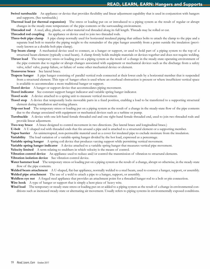
Swivel turnbuckle An appliance or device that provides flexibility and linear adjustment capability that is used in conjunction with hangers and supports. (See turnbuckle.)
Thermal load (or thermal expansion) The stress or loading put on or introduced to a piping system as the result of regular or abrupt changes in the steady-state temperature of the pipe contents or the surrounding environment.
Threaded rod A steel, alloy, plastic, or other material rod threaded along its full length. Threads may be rolled or cut.Threaded rod coupling An appliance or device used to join two threaded rods.Three-bolt pipe clamp A pipe clamp normally used for horizontal insulated piping that utilizes bolts to attach the clamp to the pipe and a
separate load bolt to transfer the piping weight to the remainder of the pipe hanger assembly from a point outside the insulation (previ-ously known as a double-bolt pipe clamp).
Top beam clamp A mechanical device used to connect, as a hanger or support, or used to hold part of a piping system to the top of a structural beam element (typically a steel beam). A clamp firmly holds multiple materials or devices together and does not require welding.
Thrust load The temporary stress or loading put on a piping system as the result of a change in the steady-state operating environment of the pipe contents due to regular or abrupt changes associated with equipment or mechanical devices such as the discharge from a safety valve, relief valve, pump failure, or failure of some other mechanical device or element.
Transverse brace See lateral brace.Trapeze hanger A pipe hanger consisting of parallel vertical rods connected at their lower ends by a horizontal member that is suspended
from a structural element. This type of hanger often is used where an overhead obstruction is present or where insufficient vertical space is available to accommodate a more traditional hanger or support.
Travel device A hanger or support device that accommodates piping movement.Travel indicator See constant support hanger indicator and variable spring hanger indicator.Travel scale A device attached to a spring unit to measure vertical movement.Travel stop A device that temporarily locks moveable parts in a fixed position, enabling a load to be transferred to a supporting structural
element during installation and testing phases.Trip-out load The temporary stress or loading put on a piping system as the result of a change in the steady-state flow of the pipe contents
due to the change associated with equipment or mechanical devices such as a turbine or pump.Turnbuckle A device with one left-hand female threaded end and one right-hand female threaded end, used to join two threaded rods and
provide linear adjustment.Two-way brace A brace designed to control movement in two directions. (See lateral brace and longitudinal brace.)U-bolt A U-shaped rod with threaded ends that fits around a pipe and is attached to a structural element or a supporting member.Vapor barrier An uninterrupted, non-permeable material used as a cover for insulated pipe to exclude moisture from the insulation.Variability The load variation of a variable-spring hanger divided by the hot load, expressed as a percentage.Variable spring hanger A spring coil device that produces varying support while permitting vertical movement.Variable spring hanger indicator A device attached to a variable spring hanger that measures vertical pipe movement.Velocity limited A term relating to snubbers in which velocity is the means of control.Vibration control device An appliance used to reduce and/or control the transmission of vibration to structural elements.Vibration isolation device See vibration control device.Water hammer load The temporary stress or loading put on a piping system as the result of a change, abrupt or otherwise, in the steady-state
flow of the pipe contents.Welded beam attachment A U-shaped, flat-bar appliance, normally welded to a steel beam, used to connect a hanger, support, or assembly.Welded pipe attachment The use of a weld to attach a pipe to a hanger, support, or assembly.Weldless eye nut A forged steel appliance that provides an attachment point for a threaded hanger rod to a bolt or pin connection.Wire hook A type of hanger or support that is simply a bent piece of heavy wire.Wind load The temporary or steady-state stress or loading put on or added to a piping system as the result of a change in environmental con-
ditions such as increased steady-state or alternating air movement. Usually refers to piping systems in environmentally exposed conditions.
19 Read, Learn, Earn October 2017
READ, LEARN, EARN: Hangers and Supports
1. Which one of these is not a type of hanger?a. metricb. pipec. rigidd. side beam
2. Which of the following creates an acoustical effect in piping systems?a. insulationb. strength of pipec. vibrationd. type of hanger
3. When a pipe passes through a penetration, what should be done or used to protect the pipe?
a. the structural hole should be at least 1 inch larger than the pipeb. fire caulkingc. slide plated. pipe sleeve
4. Who should the plumbing engineer work closely with to ensure that the building will be able to support the load of the pipe?
a. architectb. authority having jurisdictionc. mechanical engineerd. structural engineer
5. From what standard was the information in this article taken? a. ANSI/MSS SP-58-2009b. ANSI/MSS SP-59-2012c. ANSI/MSS SP-58-2015d. ANSI/MSS SP-59-2015
6. _______ can cause a chemical reaction between a hanger or support and a pipe of differing metals.
a. cleaning liquidsb. salt waterc. chemical fumesd. all of the above
7. What is the recommended minimum rod diameter for a single rigid rod hanger for the nominal pipe size of 2½ inches for steel and copper water service?
a. 3/8 inchb. ½ inchc. 5/8 inchd. ¾ inch
8. The structure must be able to handle the loads and _______ of the piping system.
a. hanger weightb. flexibilityc. durabilityd. stresses
9. Anchors and supports of piping systems must contend with the ________ and ________ of the piping system’s materials.
a. contractionb. heat and cold fluidsc. expansiond. both a and c
10. Which of the following is a type of hanger or support?a. clevisb. swivel turnbucklec. horizontal travelerd. all of the above
11. Which of the following is a T-Section hanger or support with integrated insulation that has been designed for hot-temperature piping system applications?
a. gang hangerb. two-way bracec. bracketd. hot shoe
12. What is the maximum horizontal pipe hanger spacing requirement for 2½-inch water service using steel pipe and 3½-inch water service using copper tube?
a. 9 feetb. 10 feetc. 11 feetd. 12 feet
ASPE Read, Learn, Earn Continuing EducationYou may submit your answers to the following questions online at aspe.org/readlearnearn. If you score 90 percent or higher on the test, you will be notified that you have earned 0.1 CEU, which can be applied toward CPD renewal or numerous regulatory-agency CE programs. (Please note that it is your responsibility to determine the acceptance policy of a particular agency.) CEU information will be kept on file at the ASPE office for three years.
Notice for North Carolina Professional Engineers: State regulations for registered PEs in North Carolina now require you to complete ASPE’s online CEU validation form to be eligible for continuing education credits. After successfully completing this quiz, just visit ASPE’s CEU Validation Center at aspe.org/CEUValidationCenter.
Expiration date: Continuing education credit will be given for this examination through October 31, 2018.
CE Questions — “Hangers and Supports” (CEU 252)Test written by Hal Alvord, CPD, GPD