GLOBAL SOLUTIONS - windserver.com · Outline: Critical Issues 3 Following the IEC 61400-12-1...
20
GLOBAL SOLUTIONS IN ENGINEERING Power Performance Testing Municipal Infrastructure Buildings Transportation Industrial Energy Environment
Transcript of GLOBAL SOLUTIONS - windserver.com · Outline: Critical Issues 3 Following the IEC 61400-12-1...

GLOBAL SOLUTIONS
IN ENGINEERING
Power Performance Testing
Municipal Infrastructure Buildings Transportation Industrial Energy Environment
Why Power Perfomance Testing?
2
Identification of turbine performance issues
• Operational issues
• Turbine losses
Standardized way to compare measured power curve to warranted
power curve
Project wide performance
Higher value for resale or project financing
Outline: Critical Issues
3
Following the IEC 61400-12-1 Standard
Proper tower positioning and instrumentation
Data filtering techniques
Measurement uncertainty
Turbine Supply Agreement Conditions
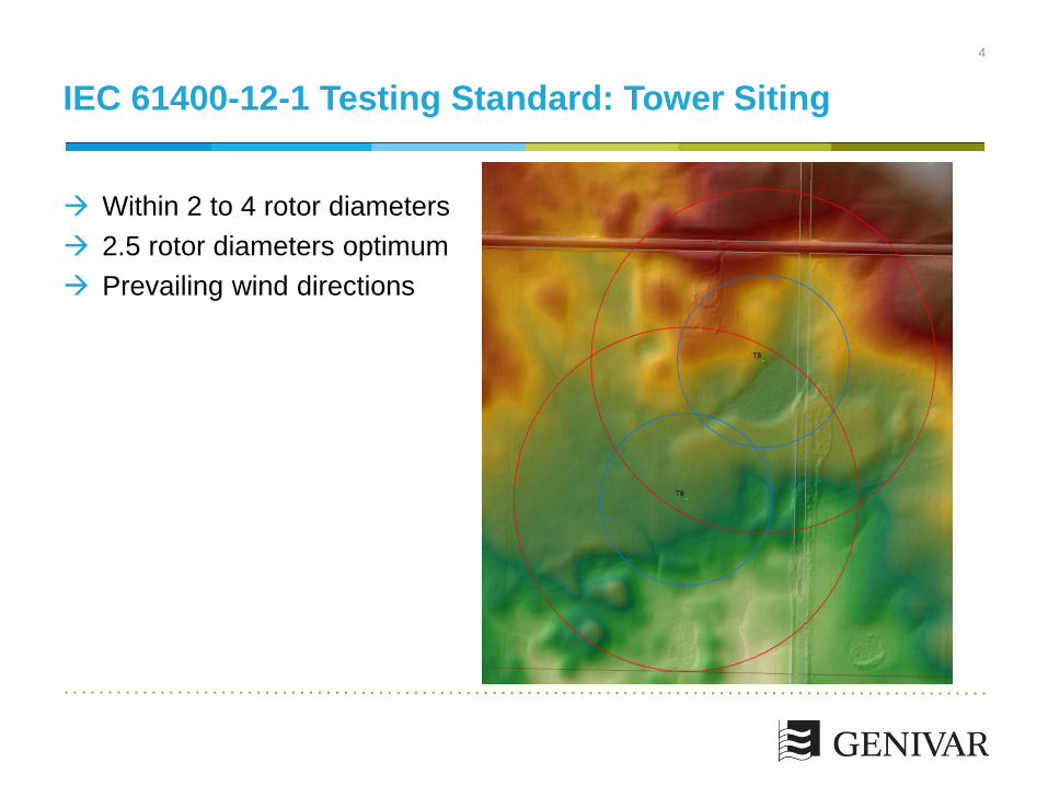
IEC 61400-12-1 Testing Standard: Tower Siting
4
Within 2 to 4 rotor diameters
2.5 rotor diameters optimum
Prevailing wind directions

IEC 61400-12-1 Testing Standard: Terrain Criteria
Criterion Description* Distance† Sector (deg)
1 Maximum slope of best fit plane
< 3% < 2L 3600
2 Maximum terrain variation from
best fit plane < 0.04(H+D) < 2L 3600
3 Maximum slope of best fit plane
< 5% 2L – 4L Measurement sector
4 Maximum terrain variation from
best fit plane < 0.08(H+D) 2L – 4L Measurement sector
5 Steepest slope maximum < 10% 2L – 4L Outside measurement
sector
6 Maximum slope of best fit plane
< 10% 4L – 8L Measurement sector
7 Maximum terrain variation from
best fit plane < 0.13(H+D) 4L – 8L Measurement sector
5
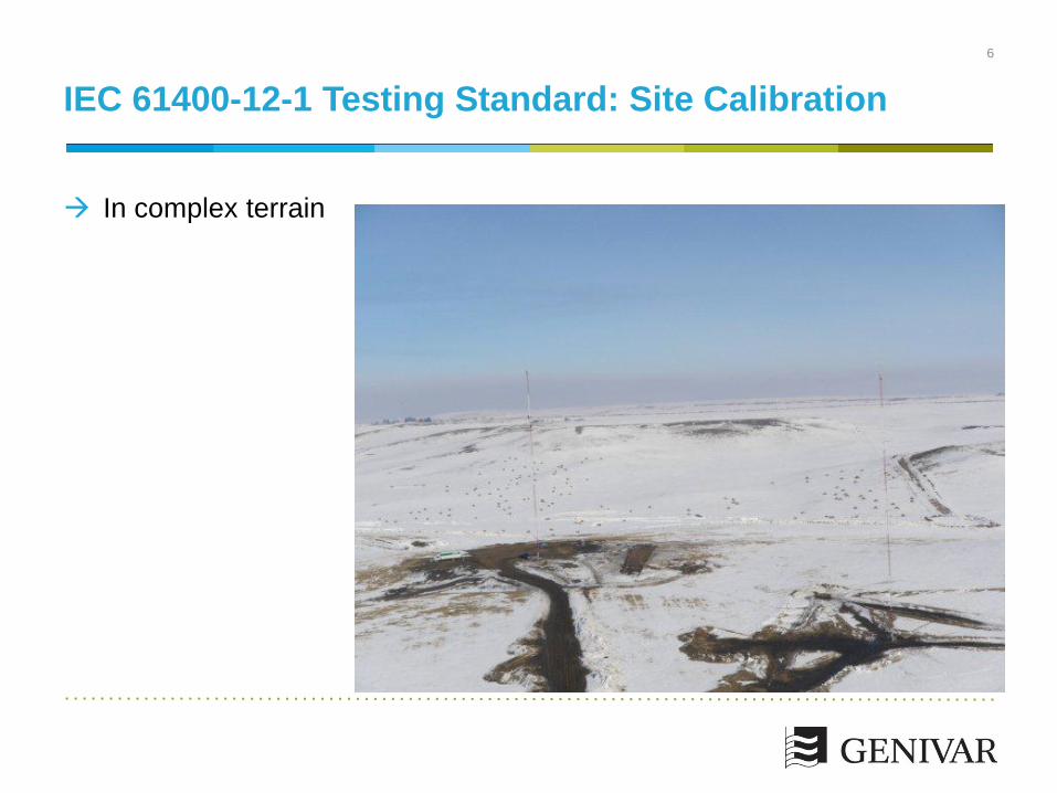
In complex terrain
IEC 61400-12-1 Testing Standard: Site Calibration
6
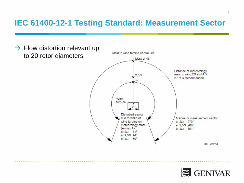
IEC 61400-12-1 Testing Standard: Measurement Sector
7
Flow distortion relevant up
to 20 rotor diameters
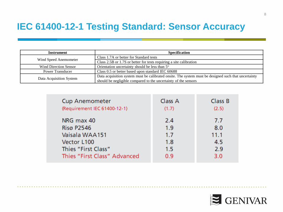
IEC 61400-12-1 Testing Standard: Sensor Accuracy
Instrument Specification
Wind Speed Anemometer Class 1.7A or better for Standard tests
Class 2.5B or 1.7S or better for tests requiring a site calibration
Wind Direction Sensor Orientation uncertainty should be less than 5o
Power Transducer Class 0.5 or better based upon standard IEC 60688
Data Acquisition System Data acquisition system must be calibrated onsite. The system must be designed such that uncertainty
should be negligible compared to the uncertainty of the sensors
8

Tower Configuration
9
Over and above the IEC standard to minimize uncertainty

Tower Configuration
Instrument Height (m) Model No. Mounting
Anemometer (2) 80 Thies First Class Advanced 4.3351.00 goal post boom
Sonic Anemometer (1) 78.3 Thies 4.3830.21.310 post mounted horizontal boom
Wind Vane (1) 78.3 Thies 4.3150.10 post mounted horizontal boom
Temp/Humidity Probe (1) 77 RM Young 41382 , 41003 mounted on tower
Barometric Pressure 77 RM Young 61302 mounted on tower
Anemometer (1) 59 Thies First Class Advanced 4.3351.00 tilt down boom
Wind Vane (1) 59 Thies 4.3150.10 tilt down boom
Anemometer (2) 39 Thies First Class Advanced 4.3351.00 tilt down booms (2)
Temperature Sensor (1) 2 RM Young 41342, 41003 mounted on tower
Anemometer (1) 10 Thies First Class Advanced 4.3351.00 tilt down boom
Precipitation Sensor (1) 2 Thies 5.4103.20.041 short custom boom
10

Tower Configuration
11

Tower Configuration
12
Sufficient separation between sensors
and tower
Clean configuration

Tower Configuration
13

Tower Orientation
14

Data Filtering: Turbine Operational Envelope
15
Inflow Angle (8 degrees)
Shear (0.2)
Turbulence Levels (IEC Standard Class)
Temperature
Precipitation
Blade Soiling
Icing
Turbine status codes
Data Collection
16
1-second data
Detailed turbine status data
Thorough data monitoring program (calibration and test)

Conditions specified in anemometer
documentation
Class 1 conditions for the Vector A 100L2
Measurement Uncertainty: Anemometer Accuracy
17
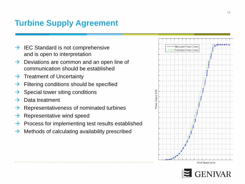
IEC Standard is not comprehensive
and is open to interpretation
Deviations are common and an open line of
communication should be established
Treatment of Uncertainty
Filtering conditions should be specified
Special tower siting conditions
Data treatment
Representativeness of nominated turbines
Representative wind speed
Process for implementing test results established
Methods of calculating availability prescribed
Turbine Supply Agreement
18
Following IEC standard
Instrumentation and Tower positioning
Data collection
Data filtering conditions: minimizing uncertainty
Turbine supply agreement considerations
Conclusions
19