Geocentric Design Code
92
Geocentric Design Code Copyright © 2001-16 Russell Randolph Westfall Last revised: November 21, 2016 Geocentric Design Code is a framework of comprehensive design guidance serving as a virtual template of broad applicability. In as much as design entails shaping space (informed by time where relevant), the rich pattern variability and intrinsic dynamism engendered by the geometry of the code’s simple Archimedean foundational form naturally affords a tool for such in most engineering and architectural endeavors. All so-designed artifacts are integrable by reason of the form’s spherical basis keyed to, and grounded by, the convenience of earth common to all. Beyond aforementioned professional realms, the code is intended for any student of design who might be inclined to a puzzle-solving approach in framing sublime potentiality with a practical - as well as sustainable - living foundation. To that end, code concepts and their simplest applications are conveyed in this document via series of illustrations attended by short blocks of text. Mathematical expressions are included where deemed useful, but are generally not required for basic understanding. Perhaps the biggest challenge here is for someone in one field to grasp the abstract reasonings behind applications of others. However, in doing this, the design horizons of any effort should expand, and hopefully the task will be eased by the underlying geometry that makes the code a wholistic enterprise. As such, the code is sequentially organized into 7 parts with an order that aims to render the most economic flow of ideas. Code orientation builds a conceptual model, then centers the constituent spheres of its geometric foundation to earth before exploring its pattern attributes. Next, cube-based abodes are built upon the foundation to manifest an architectural style that expresses a spherical earth and cosmic expansiveness amid compact comfort. Thirdly rolling transport draws on fixed and dynamic symmetries intrinsic to the geometry’s wheel orientation to guide the design of moving earth-bound constructs. Wheel/abode fusion methods are expanded to include polytechnic integration of functionalities to conceptualize a general mobility template. Fuller integration is applied to the abode and earth with ground design methods of wave forming in grid infrastructure contexts. After detailing such, wheel extrapolations address air, marine, and spacecraft as well as driven or driving fluid dynamic constructs. Finally, artifacts that project from the earth architecturally, electromagnetically, and independently employ extra-topographic guidelines. Orientation – p.2 – elements of space; reasoned accretion; square formation; the cuboctahedron; bodal manifestations; the geocentric cuboda; universal positioning; alternative rotations; bode growth; pattern attributes; geometric interplay; indefinite accretion Cube-based Abodes – p.15 – hexahedral accretion; celestial co-cubes; prime cube projection; co-cube conventionality; architectural reunion; profile characteristics; angular measurements; rectilinear rounding; passive breathability; sun wall charting; rooftop organization Rolling Transport – p.28 - the bodal wheel; profile abstractions; asymmetric dynamism; application profiles; force transmissions; symmetric neutralization; the transporter template; transverse expansion; elementary rounding; rolling proportions; the macrocosmic wheel; architectural accommodation Polytechnic Integration – p.41 – wheel-abode fusion; roof options; reflected roofs; plane transformations; tetrahedral fusion; 3D orthogonalizing; full link configurations; vector reorientations; the bodal shift; hexagonal alternates; cubical incorporation; universal spheres Ground Design – p.54 - grid alternatives; bodal prisms; grid junctures; CBA embanking; P-R grid berming; diamond waveforms; topographic variations; architectural options; concave contouring; outdoor rooms; flat grading; ground formulas Wheel Extrapolations – p.67 - wheel-based abode; diamond grid structures; abstract path; path manifestations; code bridges; template aircraft; airflow surfaces; marine vessels; fluid dynamic cubodas; bodal turbines; the disc orientation; directional discs Extra-topographic Guidelines – p.80 - grid context; foundation pads; pad interiors; building basics; optional roof forms; code towers; the electrodynamics cuboda; bodal oscillations; field-encoded spheres; rocket geometry; streamline curvatures; wholistic rocketry Illustration references: bL, bCl, bC, bCr, bR, aL, aCl, aC, aCr, and aR refer to (e.g.) above right, below center left, etc. Copyright statement: aside from fair usage applications, users are allowed only those copies necessary for their personal or professional use. Copyright protects distribution of expressions - not the ideas, methods, etc., expressed. Therefore, as far as the code is concerned, ideas and methods expressed here may be applied freely.
-
Upload
russ-westfall -
Category
Design
-
view
150 -
download
2
Transcript of Geocentric Design Code

Geocentric Design Code
Copyright © 2001-16 Russell Randolph Westfall Last revised: November 21, 2016
Geocentric Design Code is a framework of comprehensive design guidance serving as a virtual template of broad
applicability. In as much as design entails shaping space (informed by time where relevant), the rich pattern variability
and intrinsic dynamism engendered by the geometry of the code’s simple Archimedean foundational form naturally
affords a tool for such in most engineering and architectural endeavors. All so-designed artifacts are integrable by
reason of the form’s spherical basis keyed to, and grounded by, the convenience of earth common to all.
Beyond aforementioned professional realms, the code is intended for any student of design who might be inclined to
a puzzle-solving approach in framing sublime potentiality with a practical - as well as sustainable - living foundation.
To that end, code concepts and their simplest applications are conveyed in this document via series of illustrations
attended by short blocks of text. Mathematical expressions are included where deemed useful, but are generally not
required for basic understanding. Perhaps the biggest challenge here is for someone in one field to grasp the abstract
reasonings behind applications of others. However, in doing this, the design horizons of any effort should expand,
and hopefully the task will be eased by the underlying geometry that makes the code a wholistic enterprise.
As such, the code is sequentially organized into 7 parts with an order that aims to render the most economic flow of
ideas. Code orientation builds a conceptual model, then centers the constituent spheres of its geometric foundation
to earth before exploring its pattern attributes. Next, cube-based abodes are built upon the foundation to manifest an
architectural style that expresses a spherical earth and cosmic expansiveness amid compact comfort. Thirdly rolling
transport draws on fixed and dynamic symmetries intrinsic to the geometry’s wheel orientation to guide the design of
moving earth-bound constructs. Wheel/abode fusion methods are expanded to include polytechnic integration of
functionalities to conceptualize a general mobility template. Fuller integration is applied to the abode and earth with
ground design methods of wave forming in grid infrastructure contexts. After detailing such, wheel extrapolations
address air, marine, and spacecraft as well as driven or driving fluid dynamic constructs. Finally, artifacts that project
from the earth architecturally, electromagnetically, and independently employ extra-topographic guidelines.
Orientation – p.2 – elements of space; reasoned accretion; square formation; the cuboctahedron; bodal
manifestations; the geocentric cuboda; universal positioning; alternative rotations; bode growth; pattern attributes;
geometric interplay; indefinite accretion
Cube-based Abodes – p.15 – hexahedral accretion; celestial co-cubes; prime cube projection; co-cube
conventionality; architectural reunion; profile characteristics; angular measurements; rectilinear rounding; passive
breathability; sun wall charting; rooftop organization
Rolling Transport – p.28 - the bodal wheel; profile abstractions; asymmetric dynamism; application profiles;
force transmissions; symmetric neutralization; the transporter template; transverse expansion; elementary rounding;
rolling proportions; the macrocosmic wheel; architectural accommodation
Polytechnic Integration – p.41 – wheel-abode fusion; roof options; reflected roofs; plane transformations;
tetrahedral fusion; 3D orthogonalizing; full link configurations; vector reorientations; the bodal shift; hexagonal
alternates; cubical incorporation; universal spheres
Ground Design – p.54 - grid alternatives; bodal prisms; grid junctures; CBA embanking; P-R grid berming;
diamond waveforms; topographic variations; architectural options; concave contouring; outdoor rooms; flat grading;
ground formulas
Wheel Extrapolations – p.67 - wheel-based abode; diamond grid structures; abstract path; path
manifestations; code bridges; template aircraft; airflow surfaces; marine vessels; fluid dynamic cubodas; bodal
turbines; the disc orientation; directional discs
Extra-topographic Guidelines – p.80 - grid context; foundation pads; pad interiors; building basics;
optional roof forms; code towers; the electrodynamics cuboda; bodal oscillations; field-encoded spheres; rocket
geometry; streamline curvatures; wholistic rocketry
Illustration references: bL, bCl, bC, bCr, bR, aL, aCl, aC, aCr, and aR refer to (e.g.) above right, below center left, etc.
Copyright statement: aside from fair usage applications, users are allowed only those copies necessary for their
personal or professional use. Copyright protects distribution of expressions - not the ideas, methods, etc., expressed.
Therefore, as far as the code is concerned, ideas and methods expressed here may be applied freely.

Geocentric Design Code - Part I - Orientation - 2
Copyright © 2001-16 Russell Randolph Westfall Last revised: November 21, 2016
To appreciate and employ the code’s conceptual model to the fullest, it is built from elemental spheres before the
centermost is radially transfixed and coaxially keyed to earth - with alternative axes yielded by the completed cluster’s
underlying geometry enabling universal positioning of pattern attributes introduced.
Overview: Part I begins with the conceptual model’s initial construction steps in which elements of space to three
dimensions are formed in a natural manner before advancing to a reasoned accretion of spheres. Upon yielding the
parallelism and perpendicularity of square formation, observations of such guide subsequent sphere placements to
complete the cuboctahedron. From its bodal manifestations of spheres, planes and linear structure, the rotational
axis abstracted is transfixed to an earth keyed to the cluster’s common central sphere to form the faceted geocentric
cuboda. In conjunction with its natural axis, the form’s innate equatorial axis enables universal positioning that with
easily derived alternative axes spin pattern elements of any symmetric orientation to be located at any longitude and
latitude. An exploration of bode growth geometry then informs pattern attributes the boundless outward generation
and inward divisibility of which exhibit infinite customizability. Possibilities grow with the spherical and conic sections
of geometric interplay which join the potentiality of universal centered-ness in an indefinite accretion of spheres.
Elements of Space - 3 - integral sphere-point specs; natural accretion; line, plane, and tetrahedral formation
Reasoned Accretion - 4 - tetrahedral sphere-pairs; faux orthogonality; sphere 5 parallelism and perpendicularity Square Formation - 5 - sphere 6 reflection; 4-sphere square; 6-sphere cluster common sphere; planar alternation
The Cuboctahedron - 6 - assessment-based accretion; full vertex and hexagonal formation; 13-sphere completion
Bodal Manifestations - 7 – spherical cluster; structural framework; crystalline planes; external/internal expressions
The Geocentric Cuboda - 8 - bodal orientations; opposing sphere alignments; radially-transfixed center/earth-sphere
Universal Positioning - 9 - primary longitudinal rotation; opposing equatorial vertices; latitudinal element positioning
Alternative Axes - 10 - opposing equatorial elements; mid-element axes; secondary rotations; symmetric positioning
Bode Growth - 11 - intrinsic tetrahedra; space-filling square pyramids; octahedral completion; tetrahedral centering
Pattern Attributes - 12 - tetrahedral divisibility; polyhedral interfacing; internal/external equivalence; customizability
Geometric Interplay - 13 - line axis; sphere-sectioned forms; cone rotations; innate conic sections; wave formation
Indefinite Accretion - 14 - growth directions; accretion rules; triangular ambiguity; basic dueling pattern possibilities

Geocentric Design Code - Part I - Orientation - 3
Copyright © 2001-16 Russell Randolph Westfall Last revised: November 21, 2016
Elements of Space
The geometric foundation of the code’s conceptual model is built with spheres. In such light, the sphere is regarded as an equal and
omnidirectional expansion of a dimensionless point. In occupying the sphere’s center, such a point is vitally integral to that sphere
such that the point element is regarded as a contracted sphere as much as the sphere is viewed as an expanded point.
To build the form of the model’s geometric foundation, all sphere dimensions are specified to be equal, as are distances from sphere
center-points to neighboring sphere surfaces [aR]. The latter is uniquely met at relational points of contact between sphere surfaces
that coincide and confirm formation of 1-dimensional lines spanning spheres’ center-points. A 3rd sphere placed in mutual contact
with established spheres is free to in essence orbit that line [bL]. This type of placement is referred to as planar nesting.
The equilateral triangle delineated by the lines joining the 3 sphere center-points minimally constitutes a 2-dimensional plane [aC-R].
A 4th sphere deep-nested into the 3-sphere cluster forms an underlying structure that is characterized as a minimal 3-dimensional
solid termed the tetrahedron [bL-R]. The 4 spheres thus arranged comprise the most complex cluster in which each sphere is in
direct contact with all of the remaining spheres. The 4-sphere cluster also signifies completion of a natural accretion of spheres.
Tetrahedron

Geocentric Design Code - Part I - Orientation - 4
Copyright © 2001-16 Russell Randolph Westfall Last revised: November 21, 2016
Reasoned Accretion
To forestall the random disorder of indiscriminate deep-nesting, the 4-sphere tetrahedral cluster is viewed as 2 sphere-pairs [aL].
With one line serving as an axis, the underlying tetrahedron is rotated such that it meets the other line [aCl-Cr]. The concept of
perpendicularity is then joined by that of parallelism if the form is rotated further such that the spaces around the intersecting lines
are equivalent [aR]. In the cluster thus-oriented, however, perpendicular and parallel lines are only so in the plane visualized [bL].
True perpendicularity and parallelism is attained by first joining sphere center-points from each pair [aC]. A 5th sphere is then planar
nested into the shared sphere-pair and rotated about its line to a position such that the line joining 5 to the horizontal pair’s sphere
truly parallels that of the vertical sphere-pair [aR, bL]. The angle made between it and the horizontal line equals that made by the
line joining 5 to the vertical-pair sphere and the line joining that sphere to the opposing horizontal sphere - a true right angle [bC-R].
5

Geocentric Design Code - Part I - Orientation - 5
Copyright © 2001-16 Russell Randolph Westfall Last revised: November 21, 2016
Square Formation
Before placing sphere 6, focus returns to the tetrahedral cluster oriented to accentuate the apparent perpendicularity of its sphere
pairs [bL]. The 4 lines joining spheres not of their aligned pairs delineate a complete circuit of apparent right angles. Lines making
these angles are projected onto the plane visualized, and are not parallel (or perpendicular) in any non-parallel plane.
However, the appearance of such qualities suggests another basic form which is realized by placing sphere 6 in a manner that
reflects sphere 5’s placement [aC]. The underlying square made by the 4-sphere cluster completes a circuit of true right angles and
is characterized by an even number of parallel sides that neither converge nor diverge [aR]. The square exhibits 2-dimensional
symmetry and planar uniformity in its innate intersections. The greater cluster is assessed by viewing all of its 6 spheres [bL-C].
From such perspective, it is evident that only one sphere is in contact with, or common to, each of the remaining spheres. Of those 5
spheres, 2 are in common with each of the 4 and 3-sphere clusters that define an underlying square and triangle, respectively [aR].
Thus the two basic plane types share a common line that joins the center-points of their common spheres.
6

Geocentric Design Code - Part I - Orientation - 6
Copyright © 2001-16 Russell Randolph Westfall Last revised: November 21, 2016
The Cuboctahedron
The two key 6-sphere assessments are applied to subsequent sphere placements [aL]. By deep-nesting sphere 7 into a 3-sphere
cluster comprised of the common sphere and 2 square side spheres, an additional triangle and right angle are formed [aC]. Sphere
8 nested similarly completes another square so that an alternation of squares and triangles converge at one vertex [aR]. Spheres 9
and 10 are then deep-nested into the common sphere and the remaining sides of each square cluster [bL].
By flipping the 10-sphere cluster over, a complete layer of 6 spheres surrounding the common sphere is shown with the underlying
hexagon of alternately-oriented triangles [aC]. Of the 6 deep-nesting possibilities presented, space allows for only 3 more sphere
placements. Sphere 11 is placed by adhering to the guiding principle of square/triangle alternation [aR, bL]. Spheres 12 and 13
follow similarly into the remaining vacancies to complete a cluster of 12 outer spheres surrounding one common center sphere [bC].
The underlying completed form created by the 13-sphere cluster invariably exhibits alternation of squares and triangles and is most
commonly referred to as a cuboctahedron [aR]. Because this term is cumbersome in repeated use, it is sometimes shortened to
cuboda, but it is more often shortened further to bode - with bodal being its qualifying adjective.
11
11
12
13
8
7 Common Sphere
Geocentric Design Code - Part I - Orientation - 7
Copyright © 2001-16 Russell Randolph Westfall Last revised: November 21, 2016
Bodal Manifestations
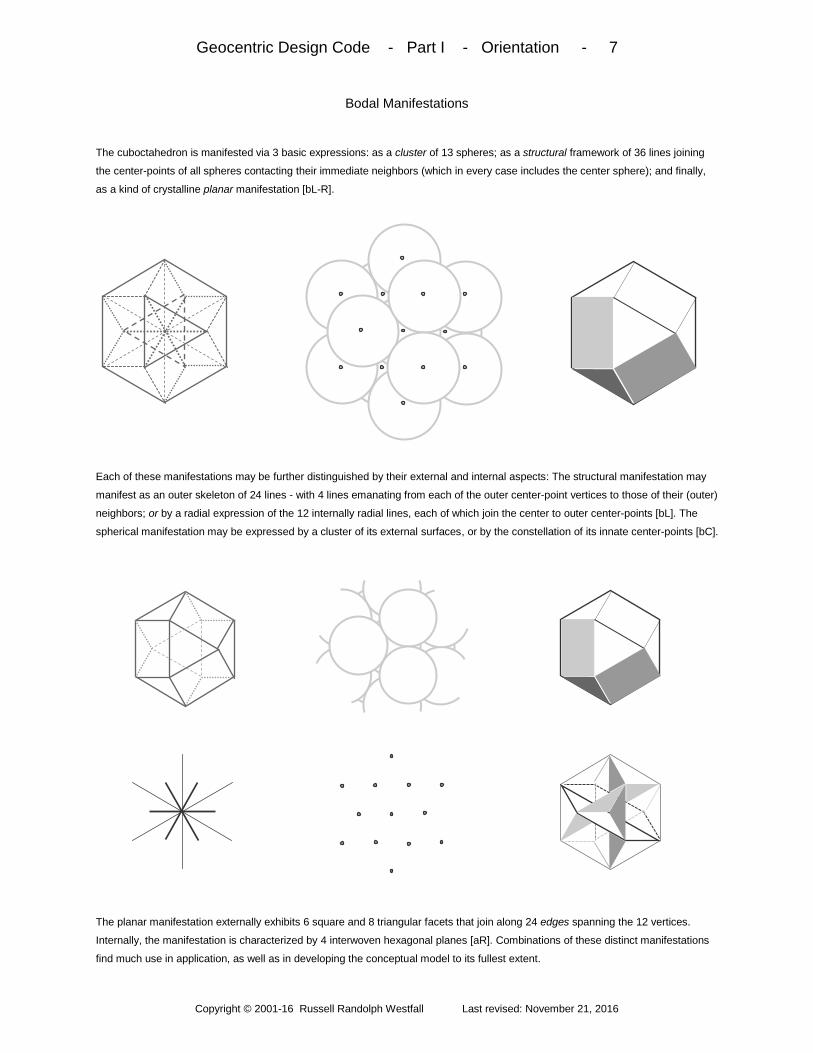
The cuboctahedron is manifested via 3 basic expressions: as a cluster of 13 spheres; as a structural framework of 36 lines joining
the center-points of all spheres contacting their immediate neighbors (which in every case includes the center sphere); and finally,
as a kind of crystalline planar manifestation [bL-R].
Each of these manifestations may be further distinguished by their external and internal aspects: The structural manifestation may
manifest as an outer skeleton of 24 lines - with 4 lines emanating from each of the outer center-point vertices to those of their (outer)
neighbors; or by a radial expression of the 12 internally radial lines, each of which join the center to outer center-points [bL]. The
spherical manifestation may be expressed by a cluster of its external surfaces, or by the constellation of its innate center-points [bC].
The planar manifestation externally exhibits 6 square and 8 triangular facets that join along 24 edges spanning the 12 vertices.
Internally, the manifestation is characterized by 4 interwoven hexagonal planes [aR]. Combinations of these distinct manifestations
find much use in application, as well as in developing the conceptual model to its fullest extent.

Geocentric Design Code - Part I - Orientation - 8
Copyright © 2001-16 Russell Randolph Westfall Last revised: November 21, 2016
The Geocentric Cuboda
In addition to the form’s basic manifestations, the cuboda may be oriented to 4 prime alignments characterized by symmetry of the
orientation’s dominating element - triangle, line (edge), point (vertex); and square - in at least one-dimension. If the vertex-up bode
cluster (with superimposed structure) is turned to a triangle-out perspective, 6 pairs of opposing spheres transfix the center sphere
[bL]. The structure is then removed with exception of the line(s) joining one set of 3 aligned spheres [bC].
With the foremost spheres removed to reveal the central sphere transfixed by one line to suggest an axis of rotation, a naturally
corresponding earth sphere is evoked in light of its universal commonality [aR]. The greater arrangement is termed the geocentric
cuboda [bL]. Although joining earth-sized outer spheres by default, it may be scaled to any greater or lesser degree if axis and outer
vertices coincide properly [bC]. Minus radial lines also (excepting the coaxial line), the outer structure is termed the bodal shell [bR].
k

Geocentric Design Code - Part I - Orientation - 9
Copyright © 2001-16 Russell Randolph Westfall Last revised: November 21, 2016
Universal Location
With vertex-up coaxial alignment of earth and the bodal shell, the latter is rotated relative to the former in a maneuver termed
primary rotation by which symmetrically-oriented geometric elements - vertex, triangle, edge, and square - may be positioned
directly over the equator at any longitude, at any time. From the square-out position [aR], an orthogonal pair of opposing
horizontally-aligned vertices signifies an extended intrinsic line uniquely residing in the equatorial plane [bL].
Because the horizontal line also passes through the center of the earth and fully transfixes that sphere, this line functions as an
imaginary equatorial axis [aR]. With the “poles” of such an axis positioned 90° to either direction of a longitude of interest, prime
bodal elements may undergo secondary rotations to located them directly over any latitude of a particular longitude. Thus the
vertex-up orientation is unique in enabling all symmetrically-aligned elements to be positioned over any earth location at any time.
Equatorial Axis
Equatorial View
Polar View

Geocentric Design Code - Part I - Orientation - 10
Copyright © 2001-16 Russell Randolph Westfall Last revised: November 21, 2016
Alternative Axes
In addition to the opposing equatorially-aligned vertices, primary rotation of the bodal shell presents opposing pairs of squares,
edges, and triangles that situate orthogonal to the equatorial plane which bisects these elements symmetrically. For this reason, and
because the elements’ centers are readily determined, lines joining center-points of opposing elements and passing through earth’s
center pose additional equatorial axes that allow symmetric, though alternatively-oriented, elements to undergo secondary rotations.
Specifically, the mid-edge axis latitudinally positions polar-oriented triangles; polar–oriented lines and longitudinal vertices are
positioned by mid-triangle axes; and the mid-square axis rotates skewed squares. Together with universal positioning, such
capability allows all elements of all symmetric alignments - and the patterns they represent - to be located anywhere.

Geocentric Design Code - Part I - Orientation - 11
Copyright © 2001-16 Russell Randolph Westfall Last revised: November 21, 2016
Bode Growth
Exploration of bode pattern geometry begins by disregarding geocentric context and observing how the form is comprised of 8
tetrahedra, and how its 4 hexagons base 3 each [aL]. Each 3 frame (edge-to-edge) an oppositely-oriented tetrahedron. Occupying
spaces between the tetrahedral faces are forms termed square pyramids [aCl-R]. If the perspective of this form’s isolated 5-sphere
cluster is turned orthogonally, an additional sphere nested into it mirrors the bode’s central sphere [bL-Cl].
The underlying structure of the 6-sphere cluster regarded independently of the bode is termed an octahedron, a form comprised of 3
internal squares encased by 8 triangles [aCr]. If the octahedron is regarded in its bodal context [aR], 4 of the bode’s 8 outer triangles
are extended in the mode of hexagonal alternation supplied by the growth’s 4 new oppositely-oriented triangles. If spheres are
nested into all bode square clusters, the 6 octahedra formed contribute triangles to creation of a larger octahedron [bL].
The larger octahedron doubles the dimensions of the smaller locally accreted octahedra expanding and occupying its bounding
edges and corners [aC]. Spaces between smaller octahedra are filled by tetrahedra which are signified by the presence of triangles
aligned oppositely to those of both the smaller and greater octahedron [aR].
Central Bode
Sphere
Tetrahedra
15
Octahedron
Tetrahedron
2X
Octahedron
Greater (2X)
Octahedron
O O
O O
O
O
T
T
14
Square
Pyramid
Octahedron
Central Bode Sphere

Geocentric Design Code - Part I - Orientation - 12
Copyright © 2001-16 Russell Randolph Westfall Last revised: November 21, 2016
Pattern Attributes
The inter-relationship between tetrahedra and octahedra is characterized by the triangle of one invariably interfacing that of the
other. Thus a tetrahedron is formed by deep-nesting a sphere into any octahedral triangle [bL-Cl]. In the context of a bode grown
octahedron, the newly formed tetrahedron joins the bode’s original tetrahedra to suggest a larger such form [bC].
Another (sphere nested) tetrahedron appended to the octahedron’s remaining isolated triangle effectively completes the larger
tetrahedron bounded by the 4 smaller tetrahedra with the space between them occupied by the octahedron [aCr]. The octahedron’s
existence within a form that is bode-intrinsic suggests that the pattern is inwardly divisible to any infinitesimal degree. With infinite
growth potential 7, the bode pattern is freely customizable as shown by hexagonal and rectilinear perspectives below.
Another pattern characteristic lies in the indistinguishability of the bode’s internal and external lines as each is common to a
rectilinear and hexagonal plane, with the internal line also part of a second hexagonal plane [aR, bL]. With pattern basics so
explored, the hexagonal and rectilinear perspectives of such are returned to the geocentric context [bCl-C]. Combinations of both
perspectives entail their sharp separation in the edge-out alignment [bCr], and full integration in the vertex-out alignment [bR].
Octahedron
Tetrahedron T
T T O

Geocentric Design Code - Part I - Orientation - 13
Copyright © 2001-16 Russell Randolph Westfall Last revised: November 21, 2016
Geometric Interplay
The spheres (points or vertices), lines (or edges), and planes (triangles or squares) comprising the bode pattern may interact in
ways that derive other geometric forms or impart meaning to existing elements. A simple example of the latter has already been
utilized with a line passing through a sphere’s center-point to confine its movement to that of rotation about the axis evoked [bL].
The simplest example of a derived form is the circle sectioned from an intrinsic sphere by an intrinsic plane of either type [aC]. By
the preceding pattern explorations pgs.11-12, planes parallel and are intrinsic to any plane that a bode orientation manifests. If a
plane is not oriented with that of visualization, the projection of the spherical section onto such will be an ellipse [aR]. Intrinsic axes,
or those derived by abstracting mid-points from opposing elements, may also be utilized to shape conical forms [bL-C].
Cones’ bounding slopes are defined by actual (or parallel) lines or by planar mid-lines rotated about an axis, however oriented in a
bode alignment context. From these, conic sections may be formed by alignments’ intrinsic planes. If shallower than a cone’s slope,
an ellipse is formed [aR]. If planes parallel the cone axis or slope, hyperbolas or parabolas are formed, respectively [bL-C]. Cone
slopes may also key maximum (or minimum) slopes of waves formulated from the rotating circle in the rectilinear context [bR].
Mid-triangle
Line
Line Cone
Mid-square Line
Mid-square
Axis Cone
Parallel
hexagonal Planes Cone
Mid – (skewed) Square
Line
Mid-edge Axis
Ellipse
Triangular-
bisecting
Plane
Hyperbola Parabola
Square- sectioning
Plane
Circle Sphere
Hexagonal
Plane
(Skewed) Rectilinear
Plane Ellipse

Geocentric Design Code - Part I - Orientation - 14
Copyright © 2001-16 Russell Randolph Westfall Last revised: November 21, 2016
Indefinite Accretion
Individual spheres placed freely in or around an established bode pattern are consistent with such; but for a cluster to be so, it must
be guided by pattern intersections. If orthogonal, 2 lines are sufficient to form a pattern-aligned bode cluster [aL]. If hexagonal, a 3rd
line is required. The bode pattern is extendable in (42) directions if sphere placements follow prescribed rules [aC]. Rectilinear rules
are straightforward [aR], while deep-nesting spheres into the triangular clusters poses ambiguity [bL].
This ambiguity stems from the bode’s characteristic duality. Because deep-nesting forms a tetrahedron, the triangle it nests into
must be octahedral and this may be difficult to determine (aR). Placement error leads to pattern disintegration and a disordered
cluster [bL]. Conversely, if placed correctly, the pattern is preserved and possesses the quality of every sphere potentially being a
center sphere surrounded by 12 in the same exact manner as the original [bR].
Original Center
New Center
X
?
?
no yes
X
6 Square Planes
12 Radial
Lines
24 Edges

Geocentric Design Code - Part II - Cube-based Abodes - 15
Copyright © 2001-16 Russell Randolph Westfall Last revised: November 21, 2016
Celestial co-cubes - based on squares of the universally locatable geocentric cuboda - project their pattern
uniformities from diverging positions to earth where juxtaposed guide design of an architectural style characterized by
paradoxical humble cosmic essence, compact airy spaces, and optimal solar harnessing attributes.
Overview: Part ll begins by finding an alternative to indefinite accretion in non-ambiguous hexahedral formation
which finds a home on the geocentric cuboda’s equatorial squares as a pair of celestial co-cubes. One such cube’s
primary projection has its pattern alighting to earth’s surface in a latitude independent manner unlike its variable
twin which nonetheless poses co-cube conventionality on the grid defined by it. The juxtaposed projections of each
then constitute an architectural reunion of superimposed geometries that guide design of walls, floors, and roofs –
the totality of which bears both useful and sublime profile characteristics. Structural challenges posed by abstract
rectilinearity on a spherical mass are addressed by angular measurements to set the stage for rectilinear rounding
of overarching radial layouts and open partitioned zones. Then special adaptations required for such conclude with
exploration of passive breathability attributes. Finally, an optimal alignment is utilized by customizable sun wall
charting that works in conjunction with rooftop organization of solar-related elements.
Hexahedral Formation - 16 - alternative accretion; bode plane and principle; mutual orthogonalities; cube attributes
Celestial Co-cubes - 17 - bodal shell possibilities; skewed square shortcomings; opposing equatorial based cubes
Primary Projection - 18 – primary longitudinal positioning; latitude/projection equivalence; 3-plane cube column
Co-cube Conventionality - 19 - latitudinal positioning; projection column surface orthogonality; polar-rotational grid
Architectural Reunion - 20 - co-cubes’ juxtaposition and reconstitution; prime cube roof and co-cube wall guidelines
Profile Characteristics - 21 - parallel cube planes; rotation fenestration; tilt effect and enhancement; parabolic CBA Angular Measurements - 22 - projection and oblate deviation; roof asymmetry; sloped R-values; geocentric flat roofs
Rectilinear Rounding - 23 - earth-squared circles; radial living; central 4-season pads; rotated profile interior zones
Special Adaptations - 24 - bath/utility combo; kitchen twirl; circular furniture; non-code seating; low wall partitioning
Passive Breathability - 25 - high wall ventilation; evaporative porches; circular venting, asymmetric air movement
Sun Wall Charting - 26 - CBA alignment optimality; sun path formulation; custom chart construction; 4 wall division Rooftop Organization - 27 - equatorial roofs; universal roof-centric chart; solar energy integration; reflectivity control
λ
90° - λ
N
E

Geocentric Design Code - Part II - Cube-based Abodes - 16
Copyright © 2001-16 Russell Randolph Westfall Last revised: November 21, 2016
Hexahedral Formation
To preclude the advent of bode pattern degradation while also building a complementary and most useful form, an alternative to
indefinite accretion p.14 employs a plane and principle supplied by the bode. To do so, the bode cluster is first oriented vertex-up,
with all but 4 square spheres removed [aL-C]. A 14th sphere is then placed on any sphere such that angles made with both lines
converging at the corner there equal that made by same [aR]. Another sphere placed similarly results in orthogonal planes [bL].
The next sphere placement forms 3 mutually orthogonal planes representative of the 3 spatial dimensions [aC]. A final placement
completes a 3D circuit of right angles that signify an underlying hexahedron or cube [aR]. In posing the most economic expression
of 3 dimensions, it possesses a unique innate pattern that may be infinitely expanded or divided with total uniformity [bL]. This end
result of a rational accretion of spheres complements the bode perfectly, and in the geocentric context, guides architectural design.

Geocentric Design Code - Part II - Cube-based Abodes - 17
Copyright © 2001-16 Russell Randolph Westfall Last revised: November 21, 2016
Celestial Cubes
To properly base the generalized cube on a particular bodal shell square, the coaxial alignment of the geocentric coincidence guides
selection [aCl-Cr]. In first regarding the skewed squares of this context, it is evident that they are relatively identical. A problem with
choosing one arises if the pattern of a cube appended to any of these is projected to earth and a 45° swath of latitudes is excluded
with full rotation [aR]. Theoretically, this might be resolved by regarding the bode’s 6 squares as 3 pairs of opposing squares [bL].
Because squares of any particular pair are parallel, cubes based on them exhibit 3D pattern consistency and thus each can be
viewed as an extension of the other [aCl]. However, having one pair of skewed squares serve as foundations for such cubes poses
a conflict with the other skewed pair because, while the 2 pairs are indistinguishable relative to the coaxially-aligned bode [aCr], they
are at odds with each other geometrically [aR]. Alternatively, the pair of equatorial squares distinguishes itself as one such pair [bL].
By employing equatorial squares to serve as the foundations for a pair of celestial cubes, the generalized cube’s prime attribute of
unambiguous pattern uniformity is upheld. Although one cube’s extended pattern is sufficient to include all earth latitudes [aC],
appropriating both equatorial squares for a pair of cubes enables each to guide design of a differentiated architectural element.

Geocentric Design Code - Part II - Cube-based Abodes - 18
Copyright © 2001-16 Russell Randolph Westfall Last revised: November 21, 2016
Primary Projection
Practical application of the celestial co-cubes’ 3D rectilinear patterns first requires that the cubed bodal shell undergoes primary
rotation such that a designated prime cube directly faces the longitude of a specified location, at the equator [aL-R]. So positioned, a
narrow square-based column of the cube’s intrinsic pattern is projected from the region corresponding to the location’s latitude [bL].
From a polar perspective, the projection extends from the cube’s center [bCl].
Both perspectives of the column’s relative position are manifested in a direct view through the cube’s earth-facing plane [aCr].
Beyond the magnified profile [aR], further magnification focusing on where the projection alights to earth’s surface identifies the
column’s 3 essential planes below, i.e., those parallel to and representative of the prime cube projected. The angle of incidence (λ)
at earth’s surface made by the earth-facing plane equals that of the location’s latitude expressed in degrees.
Prime Cube
Prime Cube
Projection Column
Equator
Polar-facing Plane
Earth-facing Plane
Rotation-facing Plane
90° - λ λ

Geocentric Design Code - Part II - Cube-based Abodes - 19
Copyright © 2001-16 Russell Randolph Westfall Last revised: November 21, 2016
Co-Cube Conventionality
The celestial cubes’ parallelism is broken to position the prime cube’s mate: the co-cube. Starting at the longitude opposing the
prime cube [aL-C], secondary rotation about the axis spanning opposing equatorial vertices positions the co-cube radially out from,
and directly above, a specified location’s latitude [aR]. So positioned, a column projected from the center of the earth-facing square
intersects the surface perpendicularly - as do column lines and planes with familiar vertical and horizontal alignments [bL-C].
Viewed through the column’s earth-facing square [aR], that plane’s central set of orthogonal lines coincide with those of latitude and
longitude [aR, bL]. As tangents to these may represent vectors directed toward 1) earth’s rotational axis poles, and 2) the rotation
itself [bC], the surface pattern that the projection lines attune to is termed the polar-rotational or P-R grid [bR]. For purposes here,
polar wobble or drift is not discernable by measuring tapes up to the farthest exposed lands of Arctic and Antarctic latitudes (≈ 85°).
Co- cube
Co- cube
Ground Level
Co- cube
P
R
N
S
E W P-R Grid
N

Geocentric Design Code - Part II - Cube-based Abodes - 20
Copyright © 2001-16 Russell Randolph Westfall Last revised: November 21, 2016
Architectural Reunion
Because both prime cube and co-cube projections conform to the polar-rotational grid geometrically, their alighting columns are
juxtaposed in separate profiles united by the grid orientation [bL]. Together, the celestial cubes are rejoined as their projections’
respective geometries are superimposed to serve as guidelines for the design of essential architectural components [bR].
Regarding the reconstitution as an abstract template, any line or plane paralleling those of the co-cube projection guides the design
of walls, floors, ceilings, roof support, etc. (with a slight correction p.22). Conversely, lines and planes paralleling those of the prime
cube projection serve to guide roof, ceiling, and staircase design as well as diagonal wall bracing [aR]. Because north and south
facing roofs are mutually orthogonal by virtue of their same-cube origination, each is conducive to rectilinear organization [bL].
Otherwise, the walls, doors, windows, etc. of the north and south elevations are characterized by rectilinear conventionality. A top
view depicts how the disparately sloping north and south roofs of the cube-based abode (CBA) style appear as a conventional
roofline while underscoring precise alignment to the polar-rotational grid [aR].
Co-cube Rotation-facing
Plane
Pole - Equator
Prime Cube Rotation-facing
Plane
North
Top View North or South Elevation
Pole - Equator

Geocentric Design Code - Part II - Cube-based Abodes - 21
Copyright © 2001-16 Russell Randolph Westfall Last revised: November 21, 2016
Profile Characteristics
Because the conventional aspects of CBA essentials and perspectives are well known, focus is placed on the un-conventional
profile where design of east and west walls is guided by the rotation-facing planes of both cube projections rotated relative to each
other. As such, the dueling alignments must eventually merge and may do so in any manner required or deemed appropriate [bL].
As the profile exhibits the only setting of plane parallelism among the co-cubes’ projection plane sets, local rotation between these
planes is manifested by circular fenestration designed into the east or west wall planes it is intended for [aC-R]. Such expression of
rotation emphasizes the tendency of the orthogonal roof’s tilt to incline consciousness away from the limited lateral, an effect that
diminishes the need for larger homes. The varying effect of the tilt is exemplified at select latitudes below.
Although subjective, the effect might be gauged by the net difference between vertical components of roof sections treated as
vectors in mid latitudes [bL]. There and elsewhere, the effect may be enhanced or subdued by lengthening one side relative to the
other (bCl]. With roof slopes expressed trigonometrically, required pitch rise is determinable from the run [bCr]. Regardless of the
combination of complementary slopes, reflection of co-cube lines by the prime cube roof mirrors a key parabolic attribute [bR].
| h2 – h1 | > 0
50°(40°) 30°(60°) 10°(80°) 70°(20°)
ρ
Tan ρ x Run = Rise Where ρ = λ
or 90°- λ
Rise
Run
h2
h1

Geocentric Design Code - Part II - Cube-based Abodes - 22
Copyright © 2001-16 Russell Randolph Westfall Last revised: November 21, 2016
Angular Measurements
As a general rule, the smaller the abode, the closer lines of its co-cube projected column conform to surface normals corresponding
to gravity and leveling devices based on such [bL]. Across latitudes, deviation (Δ) of earth’s slightly ellipsoidal form from a perfect
sphere is as high as 0.19° at the mid (45°) latitudes [bC]. This translates to a 5/16” lateral shift of an 8’ stud [bR].
For structural reasons, the co-cube projection yields to the local normal determined by a level or plumb line, and in so doing, reflects
symmetrically about same. Building smaller also results in the prime cube-projected roof junctures being more perfectly orthogonal.
There, relative torque contributed by each roof is determined with centers of gravity located at the midpoint of each uniform density
length [bL-Cl]. To determine the generalized balance point (Lu), the torque caused by one side is set equal to the other [bCr].
Open ceiling joist run (Lj) from the higher to the steeper roof section includes the point wherefrom bracing to the roof forms a perfect
square [aR]. The formulations also apply to collar ties. To meet sloped ceiling insulation requirements (RS), the derived formula
relates wall and flat ceiling R values specified for particular climate zones [bL]. Flat roof extensions able to shed rain water follow the
co-cube projection determined by the oblate correction factor. Such roofs invariably slope down toward the equator [bR].
Ljs = Lr /
[SinƟ + CosƟ ]
Lj = L
R / Cos Ɵ
Ls = L
jsSinƟ
Ljs
Ɵ
LR
TL ~ (L
L²/2) sinƟ
Ɵ
TR ~ (L
R²/2) cosƟ
TT = T
L - T
R
Ɵ
LL
Lu
L
Lu = L
R² CosƟ - L
LSinƟ /
[2CosƟ(LR + L
L)]
LR
East-West
Ω = ArcTan [ .99345 Tan λ ] =
geocentric latitude of the
co-cube projection
as a function
of geodetic
latitude (λ)
∆
Co-cube projection Plumb
Vertical (normal)
Reflected projection
Equator
λ = geodetic latitude
Ω
3950 mi
3963 mi
Earth-facing Plane of Co-Cube Projection
Ellipsoidal Surface Parallel Equator
Δ
λ
R-Ceiling
(RC)
R- Wall (R
W)
RS = R
W + (Cos ρ) (R
C – R
W)
ρ
RS
λ - Ω = Δ = deviation between latitude (λ) and co-cube projection (Ω). For an 8’ board:
Δ= 1/16” from 3°- 9° and 81°-87°; 1/8” for 9°-15° & 75°-81°; 3/16” for 15°-22°& 68°-75°;
¼” for 22°--32° & 58°-68°; and 5/16” for 32° -58°

Geocentric Design Code - Part II - Cube-based Abodes - 23
Copyright © 2001-16 Russell Randolph Westfall Last revised: November 21, 2016
Rectilinear Rounding
The geometries of the spherical earth and the cubed bode it centers translate to CBA roundedness that manifest in differing ways:
The co-cube projection’s earth-facing plane’s section that sphere to inform CBA rectilinearity with a radial layout of open concentric
living areas serving as a “grand room” - with sleeping/bathing areas situated at the ends of CBA’s natural east-west bias [aL-R].
Actual circular constructs may be yielded from sectioning a centrally divided co-cube projection’s intrinsic spheres [bL].
If joined cylindrically, such forms may center grand rooms as elevated masonry constructs accommodative of cartable woodstoves
(or gas furnaces), rock waterfalls, or large potted plants to match the season [aCl-Cr]. Another expression of roundness arises from
the locally manifested rotation of celestial cube projections [aR]. Aside from rounded exterior options, the open cross-sectional
asymmetry is naturally partitioned into zones in which low, dark, cozy areas open to high, light, and airy spaces [bL-R].
Co-cube
Projection
Sleeping, Bathing
Seasonal Center
Seating
Sleeping, Bathing
Access
Living, Dining, Cooking
Loft
Bath

Geocentric Design Code - Part II - Cube-based Abodes - 24
Copyright © 2001-16 Russell Randolph Westfall Last revised: November 21, 2016
Special Adaptations
CBA’s characteristic compactness necessitates efficient use of space, especially in much used areas. In the examples above, bath
and utility rooms are consolidated into one compartmentalized area capable of accommodating 3 or 4 functions simultaneously with
requisite privacy. Semi-open kitchens encircle small areas with task flow beginning at food storage. Intrinsic co-cube projection
spheres guide inside corner rounding [bL-Cl]. Circular tables and chairs are sectioned from spheres of divided projections [bCl].
Cylindrical proportioning is addressed in Part VII. With regard to sitting furniture otherwise, code applicability is limited to framing
upholstered cushioning [aCr]. Apt locations for such are against low walls where full headroom is not required (and other functions
are suitable). The juncture of an open ceiling joist provides convenient partitioning while retaining grand room openness [aR, bL]. If
joists are extended to the outside to support a porch roof, a bracing option conforms to the roof’s complementary slope [bR].
Closet
Dryer
Closet W/M H/W
7’ x 13’ Ref
Pantry
Top View
Code
Consistent
Non – Code
See p.8
PW
= Sinρ (LL – L
R Tanρ)
Open
Ceiling joist
Partition
Open Ceiling joist

Geocentric Design Code - Part II - Cube-based Abodes - 25
Copyright © 2001-16 Russell Randolph Westfall Last revised: November 21, 2016
Passive Breathability
As a rule, equator-facing wall height increases with decreasing latitude to accommodate slatted vents above doors and windows to
supplement those situated in or along their sides to admit air flow during warmer months [bL-C]. To cool that air, open ceiling joists
extended to the outside may support evaporative and air-permeable green walls or vertically stretched water-wicking materials [bR].
Alternatively, joist extensions may also support shallow evaporating reservoirs. Inside, quarter circle vents centered at the roof
juncture allow exit of warm upper-most air [bL]. Full circular vents on east and west walls pose additional outlet options [bCl]. These
may share space with glazing or be rotated to capture breezes. (Low polar-facing wall options are addressed in Part IV.) In general,
the encounter of warm rising air with ceiling plane asymmetry will result in subtle pressure and temperature differentials [bCr].
Such differentials may suffice to induce circular air flow by virtue of the asymmetry’s rotational basis. The flow may be influenced by
admitting or blocking sunlight according to season with movable flat roof planks [aR]. Air flow may also be guided by utilizing the grid
of open ceiling joists to support fixed or movable panels in every spatial dimension [bL-C]. Finally, solar chimney effects may work in
conjunction with earth tubes to enhance the temperature moderating attributes attending Part V embanking methods [bR].
T1 ~ P
1
T2 ~ P
2 Summer
Sun
Winter Sun
λ
Equator
E - W
Green or Wicking
Wall
Top View
East-west
Open ceiling joists
Movable Panels
Fixed Panel

Geocentric Design Code - Part II - Cube-based Abodes - 26
Copyright © 2001-16 Russell Randolph Westfall Last revised: November 21, 2016
Sun Wall Charting
CBA orientation toward solar noon and east-west extendibility makes it highly applicable to solar energy utilization for passive
heating, cooling, and illumination purposes - as well as simplifying construction of latitude-specific sun path charts for wall, glazing,
and shade tree planning. How chart construction is formulated begins with locally parallel, latitude (λ) sloped planes [bC].
Any plane’s intersection with a locally-centered celestial sphere defines the sun-path arc of one day, with the angular separation of
arcs keyed to earth’s changing declination (ψ) up to +/- 23.5° at the solstices. At this stage, solar noon zenith as well as sunrise and
set azimuths (ΦH) are calculable. By converting a generalized hour angle (ω) and its relationship with latitude and declination (from
x,y,z) to spherical coordinates (θ,Φ), sunrise trajectory angle (dа/dΦ) and sun position at any time of day and year can be charted.
To construct the chart (e.g.at 35° latitude), spherical coordinates are transferred to a cylinder sliced vertically at the polar azimuth
and unrolled to plot hourly altitudes (а) versus azimuths (Φ). The former corresponds to angle length and the latter is referenced to
90° (west). With summer solstice altitude over east and west (аs), the 360° chart is divided into 4 overlapping 180° charts centered
by each CBA wall’s direction. Hour angles from solar noon to sunrises and sets enable origin shifts from one to the other.
Equator E or W Pole
Φ
а ( = 90° - ϴ ) 1 h
2 h
3 h
4 h
5 h
6 h
Summer Solstice Winter
Solstice
Equinoxes
аs= arcsin[(cos23.5°)
x √ (tan2λ –tan
2ψ)]
Hour angle from solar noon to sunrise or sunset = 90° - arcsin [tanψtanλ]
April 16, Aug 26 (Ψ = -10°)
Ψ = 23.5° Sin τ
Where τ = # days (from
spring toward winter)
x 360°/365 days ω = # hrs x 15°/ hr
(from solar noon)
τ
sin 23.5°
ω cos Ψ
Solar noon zeniths = 90° - ψ
ΦH = arcsin [sinψ / cosλ]
dа/dΦ = cosΦ/tanλ
θ = ArcCos (Cosλ Cos Ψ Cosω – SinΨ Sinλ)
Φ = arcCos [ cosψ sinω / sinϴ ]
λ ψ
Z = ( Y- [sinψ / cosλ]) / tanλ
Y
Equator
Equinox Plane
Summer
solstice plane
Sinψ / cosλ X
Sin 23.5°
ψ
Equator
(θ,Φ)
Cylinder

Geocentric Design Code - Part II - Cube-based Abodes - 27
Copyright © 2001-16 Russell Randolph Westfall Last revised: November 21, 2016
Rooftop Organization
CBS roof orthogonality is naturally conducive to 3D rectilinear compartmentalization [aL]; and because the equatorially-oriented half
directly faces the exact center of all sun positions experienced throughout every day of the year [aCl-aCr], it is ideally positioned to
either reflect sunlight for cooling, or absorb it to heat water and/or generate photovoltaic electricity. Furthermore, because the roof
parallels a plane tangent to the equator at the same longitude, roof-centric sun paths are equivalent to those at 0° latitude [aR, bL].
Equatorial equivalence simplifies formulation of hourly coordinates of azimuths and altitude [aCl]; as well as the integration of solar
energy received by a roof element over time. To create the basis of a universal latitude-independent roof-centric chart, hourly angles
originate at sunrise, and the angle ϴ is projected onto a plane tangent to ϴ = 0° [aCr]. Then, upon plotting the latitude-dependent
“eclipse” of the earth [aR, bL], this chart, in conjunction with the wall chart p.26, can estimate energy received at a point over time.
To find a desired balance between low albedo photovoltaic or hot water panels and the passive cooling of a high albedo roof base
(or elements), the products of albedo (AL) and area (AR) of each are added and then divided by the total area to give the total areal
reflectivity. Skylights with removable insulated high albedo blocking elements pose an option for both daily and seasonal flexibility.
Equinox Solar Noon
Equator
Power (P) per area = K Cos Θ where K = 1 Sun = 1.36 kW/m2
Energy/m2 = ∫Pdt = ∫ K (12/π) Sin ω CosΨdω = - K (12/π) CosΨ [Cosω
2 – Cos ω
1]
Earth Eclipse Θ = ArcTan 1/(SinΦ Tanλ)
Equator
Θ (= 70°)
Summer solstice
Φ = 0°
Areal Reflectivity = Albedo(AB) x Area(A
R)
Σi A
BiA
Ri / Total Area = net albedo for that area
Ψ = 10° (Feb 23, Oct 17)
Hr 1 (ω =15°)
Θ = ArcCos [Sin ω CosΨ ] Φ = ArcCos [Cos ω CosΨ / Sin Θ]
Θ
λ
λ Local Parallel
Earth Plane

Geocentric Design Code - Part III - Rolling Transport - 28
Copyright © 2001-16 Russell Randolph Westfall Last revised: November 21, 2016
A fundamental re-conceptualization of the essential wheel engages interplay between all bode manifestations as well
as two starkly differing ways of dealing with bodal asymmetry in its quintessential circular orientation to pose a
guiding geometry for the design of rolling artifacts - primarily individual and multi-person transporters.
Overview: Part lll begins by abstracting the bodal wheel from the geometry of triangularly-oriented bode, with the
pattern of plane-sectioned spheres extended to a greater wheel that yields more profile abstractions. The wheel is
then turned to exhibit the asymmetric dynamism intrinsic to its dimension of width which finds ample expression in
application profiles. Simple economic ways of how wheel geometry facilitates force transmissions concludes
wheel rotation which then undergoes symmetric neutralization to form the pattern basis of transporter components
at rest relative to the motion afforded. Such takes form in a guiding transporter template that facilitates travel-
aligned pattern elongation as well as transverse expansion. Then upon applying elementary rounding methods to
the template-guided shell’s hard angles, duly completed transporter guidelines are quantified with 3D rolling
proportions. Part III concludes by introducing the macrocosmic wheel and the guidance it provides to wheel-
related constructs fixed to earth in the slots and slopes of architectural accommodation.
The Bodal Wheel - 29 - triangular orientation; hexagonal layered sphere sections; hub and spokes; the greater wheel
Profile Abstractions - 30 - co-spinning wheels; travel direction; traction; separation; alternate hexagon; greater radii
Asymmetric Dynamism - 31 - lateral wheel asymmetry; rotation resolution; alternating drive; asymmetric bracing
Application Profiles - 32 - layer expressions; 12 spoke wheels; depth projection; wheels within wheels; the bicycle
Force Transmissions - 33 - triangular support; tangential pull; hexagonal couplings; rim/hub equivalence; arced rims
Symmetric Neutralization - 34 - bode bisection; hexagonal shift; neutralized dynamism; at rest motion relativity
Transporter Template - 35 - h-shifted options; up/down distinctions; motion-aligned extendibility; all profile elements
Transverse Expansion - 36 - head-on template; hexagonal separation; triangular prisms; expansion and extension
Elementary Rounding - 37 - vertex spheres; cylindrical joining; parallel melding planes; internal or concave options
Rolling Proportions - 38 - quantified polyhedra; radial rounding volumes and areas; wheel bases; dishing angle
The Macrocosmic Wheel - 39 - geocentric cuboda; equatorial axis; celestial cube co-planing; circular fenestration
Architectural Accommodation - 40 - local microscopic representatives; wheel squares; slots and sloped annexes

Geocentric Design Code - Part III - Rolling Transport - 29
Copyright © 2001-16 Russell Randolph Westfall Last revised: November 21, 2016
The Bodal Wheel
To abstract the essence of the wheel from bode geometry, the form’s spherical cluster - regarded without celestial cubes or any
geocentric context - is oriented to face an underlying triangle directly [bL]. First noted from such a view is simply how the
fundamental plane type of the triangle always exhibits asymmetry in at least one of its 2 plane dimensions [bCl-Cr].
From this initial observation, wheel attributes follow by engaging the bode’s planar and structural manifestations [aR]. If the triangle’s
3 foremost spheres are removed to reveal the central cluster of spheres [bL], it is apparent that any one of those 7 is bisected by the
underlying hexagonal plane formed by the cluster to define a circle. It then follows that the circle’s structure follows that of its
bisecting plane which strongly suggests 6 spokes radiating from the central hub of a prospective wheel [bC].
With the spoked wheel derived from the hexagonal array’s central circle (or sphere), the spokes are extended through the outer
(bisected) spheres by virtue of the bode’s intrinsic pattern fully manifested with the return of the 3 foremost spheres [aR]. These
comprise integral parts of a greater bodal wheel which as a whole is circumscribed by a greater, equally pattern-intrinsic circle.
Asymmetry
Symmetry
Asymmetry

Geocentric Design Code - Part III - Rolling Transport - 30
Copyright © 2001-16 Russell Randolph Westfall Last revised: November 21, 2016
Profile Abstractions
To obtain additional information from the greater bodal wheel, focus is again placed on the central hexagonal layer of spheres and
its pattern extension from central to the outer 6 spheres. As such, each sphere is representative of a wheel by reason of its
formation via intrinsic planar bisection [bL].
A thought experiment is then applied to the arrangement in which the central wheel is considered friction-less while the outer 6 are
regarded as being frictionally engaged. Thus stipulated, rotation of one circle causes neighboring circles to spin oppositely and
alternate circles to spin in the same direction [aC]. By joining hubs of 2 co-spinning wheels, a direction of travel is defined [aR]. This
line, in conjunction with the central intersecting hexagonal line, may be viewed as analogous to an axial vector cross product [bL].
In following the rotation direction of the traveling circles, the axial vector abstractly represents an element of friction by which the
intermediary circle attains traction and spins [aC]. Other abstractions lie in how: separation of co-spinning circles is a function of
diameter [aR]; and how joining all co-spinning circles forms alternately oriented triangles and the hexagon defined by them [bL].
Otherwise, the greater wheel’s concentric circles represent sphere-layer distances expressed by constituent sphere radius [bC-R].
D D [ (√3) -1 ]
Inner &Inter-layer contacts – [(√3)/3]R
Inner triangular – [(2√3)/3 - 1]R
Central hexagonal layer – 2R
Outer hexagonal layer - 3R
Central Sphere – R
Outer contacts – √3 R
Central triangular – [(2√3)/3]R
Outer triangular – [(2√3)/3 + 1]R
Outer Inter layer contacts - [(√21)/3]R

Geocentric Design Code - Part III - Rolling Transport - 31
Copyright © 2001-16 Russell Randolph Westfall Last revised: November 21, 2016
Asymmetric Dynamism
The greater bodal wheel’s axis of rotation passes through the centers of the opposing outer triangular clusters [aL]. With those
spheres removed in a direct view, the essential asymmetry of the wheel’s dimension of width is highlighted [aC]. One of 2 basic
ways to resolve the asymmetry is to do so dynamically via rotation [aR]. Left/right symmetry is found in positions 1 and 3 (which
pose up/down symmetry also); and by 2 and 4. Such a picture constitutes a mirrored superimposition of time-lapsed events [bL].
In the structural depth of the wheel’s width dimension, transversely displaced hexagonal layers receive bracing guidance from
intrinsic cross-layer lines [aC-R]. Parallel layers situated transversely at the rim are braced similarly against lateral (sway) forces and
also attain symmetry dynamically [bL-Cr]. The alternation entailed in chasing symmetry suggests that the dynamic also guide how
the wheel is driven via oppositely-oriented triangles surrounding the axis of rotation as depicted in the profile view [bR].
Spoke Braces
Rim Hub
Spoke
1 2
3 4

Geocentric Design Code - Part III - Rolling Transport - 32
Copyright © 2001-16 Russell Randolph Westfall Last revised: November 21, 2016
Application Profiles
The intrinsic dynamism of alternating drive abstracted from the depth of the wheel’s width dimension is perhaps most simply
expressed in 2 dimensions via superimposition of outer bode triangles onto the plane of the wheel [bL]. As far as the alternatively-
oriented hexagonal pattern derived from co-spinning wheels is concerned, it finds apt expression in a 12-spoke pattern [bCl-C].
Both alternative and alternating planes are expressed by first pairing spokes, then triangles from each hexagonal orientation with
each pair staggered 60° relative to the other [aCr-R]. Alternatively, lines joining triangular and hexagonal layers may be projected
onto the plane of the wheel in an alternating manner [bL-Cl]. Another possibility is for the greater wheel’s circular hexagonal pattern
to be employed as a whole, or to be further applied to the central circle to guide bolt hole patterns, etc. [bCr].
Concentric circles of radii pegged to the greater bodal wheel may be expressed explicitly [aR], or may guide differentiation of
alternating elements [bL].Such expressions may vary from having practical relevance to being purely cosmetic with sizing, shaping,
and rounding enhanced by color and texturing. The structure of the central hexagonal plane (and its alternative) readily guides
design of the individual transporter [bR]. Intrinsic circles supply rounded arcs of properly-angled terminating tangents.

Geocentric Design Code - Part III - Rolling Transport - 33
Copyright © 2001-16 Russell Randolph Westfall Last revised: November 21, 2016
Force Transmissions
The radial pattern of (rounded) equilateral triangles poses optimal weight dispersal with minimal spokes [bL]; and with the alternative
hexagon’s spokes, rim depth requirements are reduced while inscribed triangles also reinforce strength. Torsional forces find a path
to optimal tangential pull in a solid disc’s molecularity [bCl]. Spoke configurations guided by a hexagonal hub reduce mass [bC-Cr].
In contrast to a radially spoked hub, the tangential pull of the hexagonal hub’s perimeter poses the angle of force application. The
rotational inertias of the bodal wheel’s principle geometric elements includes the parallel spokes of (3) force couplings [aR, bL].
Because the torque (T) is constant at any rim/surface position regarded as a wheel pivot point in such couplings, the geometry at
hub and instantaneous ground pivots are periodically identical with a rim-inscribed hexagon [bC].
With the hub-to-rim’s hexagonal geometry, force components are transmitted both toward the wheel’s center and to the rim to create
torques there [aR]. By such reasoning, the wheel may follow the solid disc’s spiral in discreet steps [bL]. Coupling the greater bodal
wheel’s circles poses a configuration of continuous force transmission, and if extended to the inner circle with wheel concentricity,
bearing placement and hydraulic schemes may be guided [bCl-Cr]. Wheel geometry may also frame mechanical leveraging [bR].
Rotational Inertias (I):
Triangle = (1/6) mass
x side squared
Hexagon = (5/6) mass
x side squared
F-couplings: each of 6
lengths = (1/12) mass
x [ L2 + 3D
2 ]
D
L
T = Constant
I = MR2(5π+3√3)/π
R/3

Geocentric Design Code - Part III - Rolling Transport - 34
Copyright © 2001-16 Russell Randolph Westfall Last revised: November 21, 2016
Symmetric Neutralization
In addition to resolving bodal wheel asymmetry in a dynamic manner via rotation, a very different approach to attaining symmetry
first entails regarding the bode’s planar manifestation directly - with focus placed on the vertical bisection in which the form is
naturally divided along the central hexagonal plane [aL-Cl]. Upon separating the 2 halves [aC-R], the hexagon is shown to
characterize the face of each half. Separated thus, one half is turned relative to the other [bL-C].
Upon relative rotation of 60°, the triangular orientation of each half’s hexagon is re-matched [aCr-R]. Across the 6-sided central
dividing perimeter, such a hexagonal shift results in the bode’s planar alternation being supplanted by planar mirroring in which
left/right symmetry is essentially fixed. In attaining such symmetry, the intrinsic dynamism of the wheel is effectively neutralized. The
h-shift is exhibited in 4 prime orientations of direct/top view interchangeability with corresponding profiles below them.
The neutralized wheel forms the basis of a 3D pattern by which the design of transporter components - at rest relative to the
translation motion provided by the dynamic wheel - may be guided. In perhaps the simplest application, the lines accentuated above
guide one possibility for the design of bicycle handlebar [aR].

Geocentric Design Code - Part III - Rolling Transport - 35
Copyright © 2001-16 Russell Randolph Westfall Last revised: November 21, 2016
Transport Template
The two h-shifted bodal wheel options that are horizontally aligned to any prospective rolling direction of travel may be employed as
the pattern basis for non-rolling transporter component design guidance. The up/down asymmetry that characterizes each of these
options attunes to the vertical differentiation of the ground/air interface.
Stipulated thus, the h-shifted wheel may naturally be elongated in the direction of travel without deviation from the essential bode
pattern - to the extent that any particular arrangement of front or rear facing planes may remain unchanged. Thus characterized, the
h-shifted wheel forms the basis of a virtual transporter template. It is essentially comprised of the bode pattern potentiality of
omnipresent lines, planes, and 3D forms. As such, the template is also applicable to rolling farm field machinery.
Basic bode elements may be employed in conjunction with the pattern’s equally intrinsic spheres to form circles, arcs, semi-spheres,
or rounded planes and 3D junctures, etc. Both of the template’s options (triangle or square-up) are equally valid, with selection
made according to transporter requirements. Use of the 2 vertical h-shifted wheels requires special integration addressed in Part IV.
Square-up
Air
Ground
Triangle-up
Tetrahedron
Octahedron
Geocentric Design Code - Part III - Rolling Transport - 36
Copyright © 2001-16 Russell Randolph Westfall Last revised: November 21, 2016
Transverse Expansion
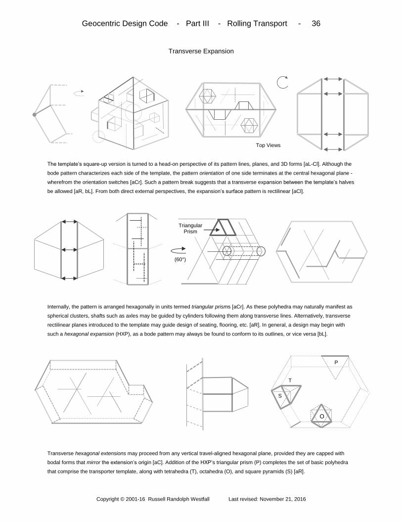
The template’s square-up version is turned to a head-on perspective of its pattern lines, planes, and 3D forms [aL-Cl]. Although the
bode pattern characterizes each side of the template, the pattern orientation of one side terminates at the central hexagonal plane -
wherefrom the orientation switches [aCr]. Such a pattern break suggests that a transverse expansion between the template’s halves
be allowed [aR, bL]. From both direct external perspectives, the expansion’s surface pattern is rectilinear [aCl].
Internally, the pattern is arranged hexagonally in units termed triangular prisms [aCr]. As these polyhedra may naturally manifest as
spherical clusters, shafts such as axles may be guided by cylinders following them along transverse lines. Alternatively, transverse
rectilinear planes introduced to the template may guide design of seating, flooring, etc. [aR]. In general, a design may begin with
such a hexagonal expansion (HXP), as a bode pattern may always be found to conform to its outlines, or vice versa [bL].
Transverse hexagonal extensions may proceed from any vertical travel-aligned hexagonal plane, provided they are capped with
bodal forms that mirror the extension’s origin [aC]. Addition of the HXP’s triangular prism (P) completes the set of basic polyhedra
that comprise the transporter template, along with tetrahedra (T), octahedra (O), and square pyramids (S) [aR].
Top Views
(60°)
Triangular Prism
P
S
T
O
Geocentric Design Code - Part III - Rolling Transport - 37
Copyright © 2001-16 Russell Randolph Westfall Last revised: November 21, 2016
Elementary Rounding
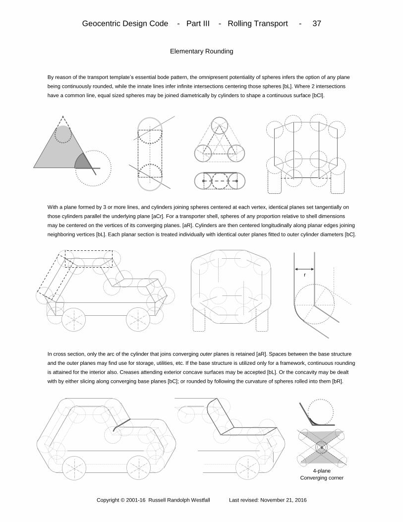
By reason of the transport template’s essential bode pattern, the omnipresent potentiality of spheres infers the option of any plane
being continuously rounded, while the innate lines infer infinite intersections centering those spheres [bL]. Where 2 intersections
have a common line, equal sized spheres may be joined diametrically by cylinders to shape a continuous surface [bCl].
With a plane formed by 3 or more lines, and cylinders joining spheres centered at each vertex, identical planes set tangentially on
those cylinders parallel the underlying plane [aCr]. For a transporter shell, spheres of any proportion relative to shell dimensions
may be centered on the vertices of its converging planes. [aR]. Cylinders are then centered longitudinally along planar edges joining
neighboring vertices [bL]. Each planar section is treated individually with identical outer planes fitted to outer cylinder diameters [bC].
In cross section, only the arc of the cylinder that joins converging outer planes is retained [aR]. Spaces between the base structure
and the outer planes may find use for storage, utilities, etc. If the base structure is utilized only for a framework, continuous rounding
is attained for the interior also. Creases attending exterior concave surfaces may be accepted [bL]. Or the concavity may be dealt
with by either slicing along converging base planes [bC]; or rounded by following the curvature of spheres rolled into them [bR].
4-plane Converging corner
r

Geocentric Design Code - Part III - Rolling Transport - 38
Copyright © 2001-16 Russell Randolph Westfall Last revised: November 21, 2016
Rolling Proportions
Polyhedra comprising the transport template are quantified above with the area (A), volume (V), and Height (H), etc. of each based
on one unit length (L). The forms are the equilateral triangle [aL]; tetrahedron (T); octahedron (O); square pyramid (S) and triangular
prism (P). Dihedral angles (DA) between planes of each form are required to determine exposed portions of rounding cylinders as
exemplified by the cross section of the common tetrahedron plus square pyramid (T+S) planar convergence [bL].
Convergence types numbered on the shell profile are quantified by proportion coefficients (KC) along with radius and length to find
the area and volume of each cylindrical wedge. Vertex convergences are lettered with their coefficients (KS) applied to areas and
volumes of spherical wedge remainders [aR]. Wheel base proportioning may be guided by co-spinning wheel separation or cycloids
attuned to wave curvature [bL-C]. Wheel dishing against sway employs a dynamic transformation angle derived in Part VI [bR].
DA’s = 60°, 90°
V = (√3)L3/2
V = (√2) L3/3
H = (√2) L
DA = 2 Tan-1(√2)
≈ 110°
O
DA’s = 1,½ “O”
V, H = ½ “O”
S
P A = (√3) L
2/4
H = √(3)L/2
L
CH =H/3 H =(√6)L/3
DA = Tan-1
(2√2)
≈ 71°
V = (√2/12) L3
T
CH = H/4
D
n =1 n = 2
Sn = D [ (n√3) -1 ]
2π D Tan-1(√6)//6
≈ 22.2°
a) T-T-S: Ks = 1 / 24
b) T-T-S-S: Ks = 1 / 12
c) T-S-P-P: Ks = 1 / 24
Vs = K
s (4π r
3/3)
As = K
s (4π r
2 )
1) P + P: KC
= 1/6 or 1/3
2) O: K
C = [π – 2 tan
-1(2√2)] / 2π
3) S + P: KC
= [π – tan-1(√2) + 90°] / 2π 4) T + P: K
C = [π – tan
-1(2√2) + 90°] / 2π
5) T + S: KC = [π – tan
-1(2√2) + tan
-1(√2)] / 2π
AC = K
C ( 2π r L ) V
C = K
C (π r
2 L)
T
S
a
c
2
3
1
4
5 b
P S
Cylindrical Wedge Spherical Wedge
Geocentric Design Code - Part III - Rolling Transport - 39
Copyright © 2001-16 Russell Randolph Westfall Last revised: November 21, 2016
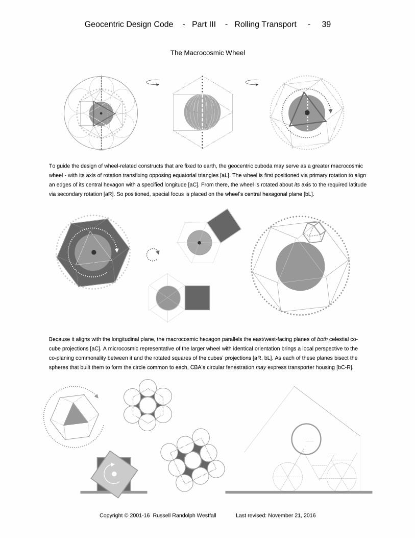
The Macrocosmic Wheel
To guide the design of wheel-related constructs that are fixed to earth, the geocentric cuboda may serve as a greater macrocosmic
wheel - with its axis of rotation transfixing opposing equatorial triangles [aL]. The wheel is first positioned via primary rotation to align
an edges of its central hexagon with a specified longitude [aC]. From there, the wheel is rotated about its axis to the required latitude
via secondary rotation [aR]. So positioned, special focus is placed on the wheel’s central hexagonal plane [bL].
Because it aligns with the longitudinal plane, the macrocosmic hexagon parallels the east/west-facing planes of both celestial co-
cube projections [aC]. A microcosmic representative of the larger wheel with identical orientation brings a local perspective to the
co-planing commonality between it and the rotated squares of the cubes’ projections [aR, bL]. As each of these planes bisect the
spheres that built them to form the circle common to each, CBA’s circular fenestration may express transporter housing [bC-R].

Geocentric Design Code - Part III - Rolling Transport - 40
Copyright © 2001-16 Russell Randolph Westfall Last revised: November 21, 2016
Architectural Accommodation
Because the cube-based abode is rectilinear, dedicated transporter housing is guided by macrocosmic wheel squares. After
longitudinal positioning via primary rotation, the wheel is rotated about its axis of opposing equatorial triangles such that a radial line
of the central hexagon radial is aligned vertically at the location’s required latitude to guide a slotted housing approach [bL-Cl].
With focus on the wheel’s local microcosmic representative, perspective shifts to a polar view where the proportion of the square’s
dimensions projected onto the polar-facing plane defines the height-to-width ratio of transporter slots housing a bicycle or 2 [aC-Cr].
With the opposing square’s projection, a double slot accommodates a family vehicle [aR]. In the sloped wheel housing approach,
the wheel is rotated such that any square’s outer edge parallels earth’s surface at the specified location [bL].
With the microcosmic representative shifting from profile to polar perspectives, focus is placed on the sloping square [aCl]. This
element guides the design of roofs intended for co-cube consistent structures annexed to CBA’s east or west walls [aCr-R]. Full
transporter/house fusion and annexation hybrids are described in Part IV.
N - S
E - W
√ 2 / √ 3 ≈ 4 / 5
∆
N - S
E - W
∆ =
Tan-1[(√2)/2]
≈ 35°
Top View
N - S
∆

Geocentric Design Code - Part IV - Polytechnic Integration - 41
Copyright © 2001-16 Russell Randolph Westfall Last revised: November 21, 2016
Fusion of vehicular and architectural design guidelines based on free and earth-bound bode geometries stem from
methods which yield universal linking intermediaries serving to expand the transport template into a general dynamic
one that introduces the capability of incorporating polytechnic functionalities via polyhedral integration.
Overview: Part IV begins by detailing the way to full wheel-abode fusion through the reconciliation of CBA and
bodal wheel geometries, then presenting rule-disciplined roof options that retain the identity of each function. One
option is characterized by reflected roofs that with wheel integrations allowed underscore the latitudinal dance of
fusing angles which lead to the concept of planar transformations. Their idealization is then shown to correspond to
a tetrahedral fusion, the form of which finds a home in the cube it bolsters to define a 3D orthogonalizing capability
with general linking intermediaries. To such, corner-centered spheres complete the basis of full link configurations
ready for application to vector reorientations in which axes of bodal wheel constructs are aligned to the direction of
template-guided transporters. Shaft centering and wing accommodation are next enabled by the bodal shift that also
introduces the incorporating possibilities of hexagonal alternates. Part IV concludes with cubical incorporation into
the hexagonal template and universal spheres that serve as external and internal links to any construct whatsoever.
Wheel-Abode Fusion - 42 - macrocosmic h-shift; tri-wings to roof; fusion formula; cross gable wheel port
Roof Options - 43 - fused gable dormers; east-west lateral fusion expansion; hybrid corner ports; option rules
Reflected Roofs - 44 - ground reflections; wheel port expansions; upper wall vents and fenestration; roof fusions
Plane Transformations - 45 - fusion plane junctures; octahedral sphere projection; arced 2D transformations
Tetrahedral Fusion - 46 – idealized 55° fusion; tetrahedron formation; tetrahedral 3D fusion recti-linearity
3D Orthogonalizing - 47 – tetrahedral cube faces; the cube link; orthogonal orientations; all bodal positions linked
Full Link Configurations - 48 - reinforced cube links; corner spheres; radii ratios; link assemblages; sphere joining
Vector Reorientations - 49 - transport template linking; bodal wheel propulsion axis; vertical axis rotors; shaft holes
The Bodal Shift - 50 - opposing bode pairs; tetrahedral bridges; rotor/housing resonance; existing plane shifts; wings
Hexagonal Alternates - 51 - orthogonal hexagons; circular and cylindrical links; crossed rectangle links; overlap radii
Cubical Incorporation – 52 - inside corner radii; multiples; abutting and apart constructs; hexagonal-expansion links
Universal Spheres - 53 - cube and tetrahedral spheres; plane sectioning; ball joints; internal spheres and cylinders

Geocentric Design Code - Part IV - Polytechnic Integration - 42
Copyright © 2001-16 Russell Randolph Westfall Last revised: November 21, 2016
Wheel-Abode Fusion
In the cube-based abode context, a framework for transporter housing is sought in which both a wall and roof section, as well as a
3-dimensional wheel expression, are engaged. To do so, the earth-centered macrocosmic wheel is positioned such that an outer
triangular edge is aligned with, and parallel to, a longitudinal tangent at a specified location [bL].
At location, the wheel’s microcosmic representative is viewed in profile, then turned to a polar perspective [aCl-C]. Thus aligned, the
wheel undergoes an h-shift to attain lateral symmetry and thus dynamic neutralization topped with matched triangles. In profile, the
matched triangles represent the wheel as a quasi-independent entity juxtaposed against the abode [aCr-R]. With the connecting
ridge held horizontal, the matched triangular “wings” are adjusted to fit the roof section as depicted from a polar perspective [bL].
The expression relating slope “ρ” (equal to latitude or its complement) to the angle of wing spread (“γ”) is termed the fusion formula.
After the tri-wing pair is bisected vertically flush with the north or south wall [aR], the wing halves minimally express the wheel as
one triangle. So crafted, what is essentially a precisely specified cross gable serves as a canopy for wheeled accommodation while
imparting to the CBA style a way of manifesting latitude from polar and top view perspectives [bL-R].
ρ Hexagonal
-shift
Microcosmic wheel
Earth’s Surface
N-S
γ = Sin-1
[ (√3/3) Tan ρ ]
γ
C /√3
F = H / Tan ρ
ρ= Tan-1( √3 Sin γ )
H= L Tan γ C = L/Cos γ
C / √3
ξ = Tan-1
[( √ 3) /3 Cos γ] ρ= Tan-1( 1 / Tan ξ )
L
ξ

Geocentric Design Code - Part IV - Polytechnic Integration - 43
Copyright © 2001-16 Russell Randolph Westfall Last revised: November 21, 2016
Roof Options
The fused cross gable, though primarily intended for transporter housing, is also applicable to entrances in general - be they doors,
windows, or vents admitting passage of air, light, people, and goods [bL]. As a general rule, dormer structures may not be extended
in ways that depart from the triangular wings’ hexagonal geometry and allow the rectilinear pattern to take over [bC].
The triangular pattern may be truncated by following the triangular pattern to effect hip style dormers [aR]. Inside these structures,
planes must invariably parallel north or south walls. Another option especially applicable to steeper gables entails transverse
extension of the tri-wing ridge to so as to form a plateaued roof section [bL]. At CBA corners [bC], hybrid roofs - juxtaposing fixed
and variable wheel/abode integration approaches - are comprised of half fusion gables and wheel-based annexations p.40.
Hybrid roofs may occupy only one (polar) side of an east or west wall to avoid obscuring CBA profile expression [aR]. With this
stipulation, hybrids may situate on diagonally opposed corners [bL]. Another rule stipulates that dedicated wheel annexations and
fusions may not exist on the same structure – unless a hybrid situates on one of the corners bookending the 2 wheel expressions to
inform them both [bR]. In general, such rules are intended to preserve intra-latitude identity and inter-latitude integrity.
Annex Fusion ρ
≈ 35° No
Corner
Top View
N-S

Geocentric Design Code - Part IV - Polytechnic Integration - 44
Copyright © 2001-16 Russell Randolph Westfall Last revised: November 21, 2016
Reflected Roofs
Another roof option is characterized by reflection of the prime celestial cube projection planes off the (ideal) horizontal surface [bL].
If such roofs are shallower than the CBA roof section, new vertical (wall) planes may be formed on the low side where steeper roofs
offer little area for windows or vents required for cooling [bR]. The reflected roof section may also extend beyond the abode.
If utilized, it is imperative that the reflected roof section (as well as the structure supporting it) does not obscure the essential
expression of CBA’s celestial cube-projected geometry. If the roof situates on a wall at the extreme east or west end, a properly
placed facial board may satisfy CBA expression [bL]. Dedicated east-west walls supporting reflected roofs may also host circular
fenestration [bC]. However, wheel annexes, either standalone or as part of hybrids, are not allowed on such.
Reflected roofs may also host wheel/abode fusions to afford longer, shallower cross gable options for transporter housing otherwise
stifled by steeper CBA roofs – while also effecting visual sociability between longitudinal neighbors. So conceptualized, such roofs
may extend to the CBA projected roof of a neighboring structure to the extent of creating enclosed courtyards [bL-R]. With the gable
extending beyond the structure and bridging a like slope on the other structure, triangular integrity is retained.
Reflected Roofs
Fusion Cross
gable
East-west
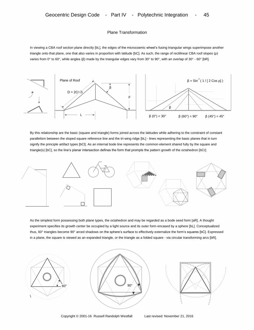
Geocentric Design Code - Part IV - Polytechnic Integration - 45
Copyright © 2001-16 Russell Randolph Westfall Last revised: November 21, 2016
Plane Transformation
In viewing a CBA roof section plane directly [bL], the edges of the microcosmic wheel’s fusing triangular wings superimpose another
triangle onto that plane, one that also varies in proportion with latitude [bC]. As such, the range of rectilinear CBA roof slopes (ρ)
varies from 0° to 60°, while angles (β) made by the triangular edges vary from 30° to 90°, with an overlap of 30° - 60° [bR].
By this relationship are the basic (square and triangle) forms joined across the latitudes while adhering to the constraint of constant
parallelism between the sloped square reference line and the tri-wing ridge [bL] - lines representing the basic planes that in turn
signify the principle artifact types [bCl]. As an internal bode line represents the common element shared fully by the square and
triangle(s) [bC], so the line’s planar intersection defines the form that prompts the pattern growth of the octahedron [bCr].
As the simplest form possessing both plane types, the octahedron and may be regarded as a bode seed form [aR]. A thought
experiment specifies its growth center be occupied by a light source and its outer form encased by a sphere [bL]. Conceptualized
thus, 60° triangles become 90° arced shadows on the sphere’s surface to effectively externalize the form’s squares [bC]. Expressed
in a plane, the square is viewed as an expanded triangle, or the triangle as a folded square - via circular transforming arcs [bR].
\
β = Sin-1
( 1 / [ 2 Cos ρ] )
L
D = 2C/√3 F
Plane of Roof
β
β
β (0°) = 30° β (60°) = 90° β (45°) = 45°
60° 90°

Geocentric Design Code - Part IV - Polytechnic Integration - 46
Copyright © 2001-16 Russell Randolph Westfall Last revised: November 21, 2016
Tetrahedral Fusion
By introducing the plane transformation with the roof fusion, a special equilateral triangular proportion superimposed on the
rectilinear background comes to light at β = 60° [aL]. To obtain this result in the fusion context, the rectilinear plane slope must be
√2: 1 ≈ 55° [aC]. Alternatively, β = 60° results from a tri-wing adjustment angle of γ ≈ 55° [aR]. Thus equating γ and ρ in the fusion
formula yields 55°. By such symmetry and the fact of both tri-wings being equilateral indicates formation of a tetrahedron [bL].
In the bode context, the tetrahedron’s 55° slope matches bode plane slopes if the form is oriented to set on any one its triangles or
squares [aC-R]. In the latter case, the tetrahedron matches the slope of an octahedral square. In the former case, the tetrahedron
matches another (oppositely-oriented) tetrahedron such that octahedral overlap is manifested [bL]. The parallel sets of orthogonal
lines characterizing the pair thus joined suggests the fusion possesses a quality of 3-dimensional recti-linearity [bCl].
This attribute of rectilinearity is reinforced by the pairing’s top view [aCr], as well as by the form’s previously observed attributes of
rectilinear perpendicularity and parallelism [bCr-R]. Because the triangular tetrahedron associates so intrinsically with the rectilinear,
it plays a key role in integration schemes, primarily pertaining to the latitude independent geometry of the transport template.
Octahedron Tetrahedron
β = 60° @ ρ ≈ 55° and @ γ ≈ 55° 55° ≈ Sin-1 [(√3/3)Tan 55°]
β = 60° ρ = 55°
γ ≈ 55°
T/O
O/T

Geocentric Design Code - Part IV - Polytechnic Integration - 47
Copyright © 2001-16 Russell Randolph Westfall Last revised: November 21, 2016
3D Orthogonalizing
Tetrahedral rectilinearly also manifests from the opposite approach in that diagonal lines spanning opposing corners of all 6 cube
faces essentially define the form [aL]. A second tetrahedron may be formed by spanning the cube’s remaining corners [aC]. Thus is
the structural weakness of the cube’s abstract ideal optimally reinforced. This attribute, in conjunction with planar transformation and
the form’s most economic expression of 3 dimensions [aR], renders the cube ideal for use as a linking intermediary [bL].
By such attributes and reasonings, the cube link functions to reorient the bode to orthogonal positions. From one perspective
(vertex-out [aC]), each prime bode alignment (edge, vertex, square, and triangle-up) is directly attained from any other orientation.
Octahedral square-to-square, triangle-to-triangle, or square-to-triangle characterize the interfaces, with the link’s innate tetrahedron
matching the octahedron’s projection onto same [aR]. Triangularly interfaced bodes may be further reoriented [bL-R].
Triangle-up Edge-up
Square-up
Vertex-up
Square-to- Triangle
Square-to-square
Tetrahedral-
inscribed cube link
Octahedral Square
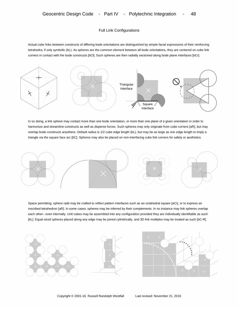
Geocentric Design Code - Part IV - Polytechnic Integration - 48
Copyright © 2001-16 Russell Randolph Westfall Last revised: November 21, 2016
Full Link Configurations
Actual cube links between constructs of differing bode orientations are distinguished by simple facial expressions of their reinforcing
tetrahedra, if only symbolic (bL). As spheres are the common element between all bode orientations, they are centered on cube link
corners in contact with the bode constructs [bCl]. Such spheres are then radially sectioned along bode plane interfaces [bCr].
In so doing, a link sphere may contact more than one bode orientation, or more than one plane of a given orientation in order to
harmonize and streamline constructs as well as disperse forces. Such spheres may only originate from cube corners [aR], but may
overlap bode constructs anywhere. Default radius is 1/2 cube edge length (bL), but may be as large as one edge length to imply a
triangle via the square face arc [bC]. Spheres may also be placed on non-interfacing cube link corners for safety or aesthetics.
Space permitting, sphere radii may be crafted to reflect pattern interfaces such as an octahedral square [aCr], or to express an
inscribed tetrahedron [aR]. In some cases, spheres may be inferred by their complements. In no instance may link spheres overlap
each other– even internally. Unit cubes may be assembled into any configuration provided they are individually identifiable as such
[bL]. Equal sized spheres placed along any edge may be joined cylindrically, and 3D link multiples may be treated as such [bC-R].
/
Square Interface
Triangular Interface
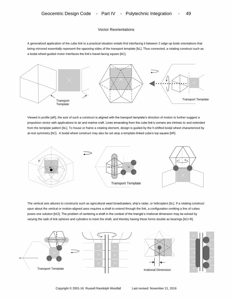
Geocentric Design Code - Part IV - Polytechnic Integration - 49
Copyright © 2001-16 Russell Randolph Westfall Last revised: November 21, 2016
Vector Reorientations
A generalized application of the cube link to a practical situation entails first interfacing it between 2 edge-up bode orientations that
being mirrored essentially represent the opposing sides of the transport template [bL]. Thus connected, a rotating construct such as
a bodal wheel-guided motor interfaces the link’s travel-facing square [bC].
Viewed in profile [aR], the axis of such a construct is aligned with the transport template’s direction of motion to further suggest a
propulsion vector with applications to air and marine craft. Lines emanating from the cube link’s corners are intrinsic to and extended
from the template pattern [bL]. To house or frame a rotating element, design is guided by the h-shifted bodal wheel characterized by
at-rest symmetry [bC]. A bodal wheel construct may also be set atop a template-linked cube’s top square [bR].
The vertical axis attunes to constructs such as agricultural seed broadcasters, ship’s radar, or helicopters [bL]. If a rotating construct
spun about the vertical or motion-aligned axes requires a shaft to extend through the link, a configuration omitting a line of cubes
poses one solution [bCl]. The problem of centering a shaft in the context of the triangle’s irrational dimension may be solved by
varying the radii of link spheres and cylinders to meet the shaft, and thereby having these forms double as bearings [bCr-R].
Transport Template Irrational Dimension
Transport Template Transport Template
Transport Template

Geocentric Design Code - Part IV - Polytechnic Integration - 50
Copyright © 2001-16 Russell Randolph Westfall Last revised: November 21, 2016
The Bodal Shift
The transport template’s edge-up bode geometry poses other planes to which cube links may interface [aL]. In one configuration,
mirrored cube links interface triangle-up bodes of opposing orientation in the context of one hexagonal plane [aC-R]. Any template
hexagonal plane may host such a bodal shift pairing, provided the pair’s linear juncture parallels the template-guided transporter’s
travel direction [aR]. Tetrahedral links bridge the pair’s opposing octahedral faces by virtue of planar transformation reasoning [bL].
In a vertical axis situation, both hexagonal shifting and expanding both bodes results in a configuration that is suitable for guiding the
design of housings or frameworks of rotating elements [aC]. Such a configuration is characterized by an oscillatory geometric
resonance between stationary and rotating elements [aR]. It also enables precise shaft centering in both plane dimensions [bL].
Another application of the bodally-shifted pairing specifically entails utilizing the template’s vertical planes [bC].
In this case as in others involving pre-existing planes that signal bode structural depth, one of the pairing is an actual h-shifted bode.
Because the juncture satisfies the travel-aligned requisite, the pair may interface cube links bridged by tetrahedra to accommodate
edge-out h-shifted bodal constructs possessing a horizontally-oriented hexagonal plane applicable to wing design, etc. [aR].
Tetrahedral Links
Transport Template
Transport Template Top View
Hexagonal Plane

Geocentric Design Code - Part IV - Polytechnic Integration - 51
Copyright © 2001-16 Russell Randolph Westfall Last revised: November 21, 2016
Hexagonal Alternates
Other integration options applicable to the transport template’s vertical planes include incorporating a triangle-out bode shifted 30° to
effectively obtain a pattern possessing vertical lines orthogonal to the direction of travel [bL]. Such an orthogonal shift (or O-shift) is
largely justified by the planar manifestation of the transformation between squares and triangles [bC].
Such manifestation is expanded to show how two orthogonal triangles - representative of orthogonal hexagonal pattern orientations
- share one arc of transformation. Because circles are intrinsic to both orientations, they form the basis of links between them [aR].
For O-shifted constructs abutting the template’s vertically-aligned hexagonal plane, a circumscribing circular plate functions as the
link, while for larger constructs extended apart from the template plane, cylindrical extensions serve as the intermediary [bL-Cl].
More specialized links are derived from orthogonally-placed rectangles proportioned to minimal hexagonal expressions [aCr-R].
Radii of circles centered on outside corners are keyed to the rectangles’ overlap [bL]. Aligned circles are joined tangentially, and
plate links may be extended transversely for constructs apart [bCl]. The value in joining links end-to-end lies in accommodating
vertically biased bode constructs [bC-Cr]. These are vertically melded, while those linking orthogonal HXP’s directly are not [bR].
L L
√3L
Transport template
bode or HXP Geometry
30°
[(√3-1)/2] x L
HXP

Geocentric Design Code - Part IV - Polytechnic Integration - 52
Copyright © 2001-16 Russell Randolph Westfall Last revised: November 21, 2016
Cubical Incorporation
Link crafting criteria include realignment economy, practical implementation, simple distinguishability of what is linked to, and
expression of their common element. To incorporate rectilinear constructs (including doors) onto the transport template’s vertical
planes, crossed rectangles keyed to hexagonal proportion again underlay the links, with circle radii pegged to inner corners [bL-C].
Configurations of such links are joined along the rectangles’ common squares [aR]. For constructs extended apart from the template
plane, their links retain rectangular melding and rounding. Abutting constructs, e.g., an intermodal container scheme, omit melding
and the link manifests in circular radius/spacing proportions [bL]. Intermediaries linking cubical constructs to an HXP’s rectilinear
planes are based on the prism form’s spherical basis [bC]. On such links, corner-centered spheres possess half-edge length radii.
Sectioned corner spheres are joined by flat circles centered on the triangular convergence below them [aR]. Configurations of such
links join square-to-square, and to encompass abutting constructs individual spheres remain as such [bL]. For constructs apart, link
extensions are melded tangentially along transverse lines, while circular under-sphere expressions remain flat as always [bC]. Cube
links joining HXP to bode constructs possess half-edge radius corner spheres only, and meld with transverse cylindrical forms [bR].
[(√3-1)/2] L
Cubical Construct
HXP HXP
Extended Link
Cubical Construct
Cube Link
HXP
Bode Construct

Geocentric Design Code - Part IV - Polytechnic Integration - 53
Copyright © 2001-16 Russell Randolph Westfall Last revised: November 21, 2016
Universal Spheres
Cube links possessing full edge length corner sphere radii evoke the alternate accretion of spheres that initially built the form, while
spheres centered on vertices of a tetrahedron utilized as a link can largely obscure the form, as in a bodal shift setting (bL). If a
sphere radius of one edge length is utilized, the tetrahedron may be virtually undiscernible [bCl].
In such case, the sphere is sectioned along planes adjacent to, or opposite of the vertex/sphere center to link square and triangle-up
constructs [aCr-R]. In general, the sphere may comprise the entire link in joining vertically and horizontally-aligned hexagonal lattice
structures [bL]. In practice, the sphere naturally interfaces cylindrical tubes and/or rods [bCl]. To avoid overlap of structural members
and attain bode-consistent tangential melding angles, relative sphere and member radii are quantified by the given expression [aCr].
Cylinders centered by, and aligned with, bode edges may also function as external links to the orientations emphasizing a square,
triangle, vertex, or edge [aR]. Because spheres represent an omnipresent potentiality in the bode pattern and may be connected to
such by a single line, they may serve (along with cylindrical extensions) as internal links to bode constructs of any orientation, as
well as to non-code constructs.
Non- Code
r / R = Cos α
α =
0°, 30°, 60°, 90°
@ - r =
R, (√3/2)R, R/2, 0
R
r
α
α

Geocentric Design Code - Part V - Ground Design - 54
Copyright © 2001-16 Russell Randolph Westfall Last revised: November 21, 2016
A deeper realm of integration entails joining celestially projected architecture to the sphere it sets upon by employing
the prism-like geometry of the earth-centered bode that extends its applicability to the surrounding environment with
supporting terrestrial waveforms serving to nourish and enhance the abode in aesthetic as well as material ways.
Overview: Part V begins by establishing complementary grid alternatives which define guiding surface foundations
for topographic constructs shaped by waveforms’ smoothest transitions from one level to another via bodal prisms.
Such are keyed to the maximum slopes of mounded grid junctures of intrinsic universal fusibility, then to the same
quantifiers of CBA embanking waves for the practical benefits as well as architectural harmony posed. Apart from
the abode, prism slopes of P-R grid berming join CBA averages via the fusion formula, as diamond waveforms
support larger flora of greater solar demand. With rudiments of ground design, topographic variations harmoniously
interface natural terrain, while architectural options enhance the abode and expand its context. Then with prism
application to concave contouring, waveform methods are sufficiently advanced to create outdoor rooms featuring
support for overhead lattices and outdoor furniture. Part V concludes by relating ideal and natural earth spheres to
derive flat grading methods that base and harmonize all grid elements quantified by ground formulas.
Grid Alternatives - 55 – P-R grid; geocentric cuboda skewed squares; latitudinal; diamond grid; grid integration
Bodal Prisms - 56 - prism orientations; elemental slopes; inherent angles; maximum wave slopes; quarter waves Grid Junctures - 57 - mundane vertices and poles; vertex-up prism; local rotation; inter- and intra-grid mounds
CBA Embanking - 58 - square-up prism; vertex-up role; 45° prism slope commonality; default embanking waveforms
P-R Grid Berming - 59 - edge-up prism; positioning pathways; sloping square; waveform berming; juncture fusions
Diamond Waveforms - 60 - edge-up sloping triangle; berm end rounding; fusion planes; orchards; slope progression
Topographic Variations - 61 - terraced berms and mounds; quarter wave translations; natural terrain interfacing Architectural Options - 62 - outside corner grid juncture waveforms; insides; embanking fusions; sunken houses;
Concave Contouring - 63 - pattern concavities; wave trough axes; plateau depressions; inside corner contouring
Outdoor Rooms - 64 - courtyard embanking; waveform seating; crest post lattice support; plateaus; wading pools
Flat Grading - 65 - ideal and real earth spheres; natural and abstract flat; construct bases; drainage; isotropic slope Ground Formulas - 66 - wave numbers; max slope to curvature circles; wave areas and volumes; lot proportions
N
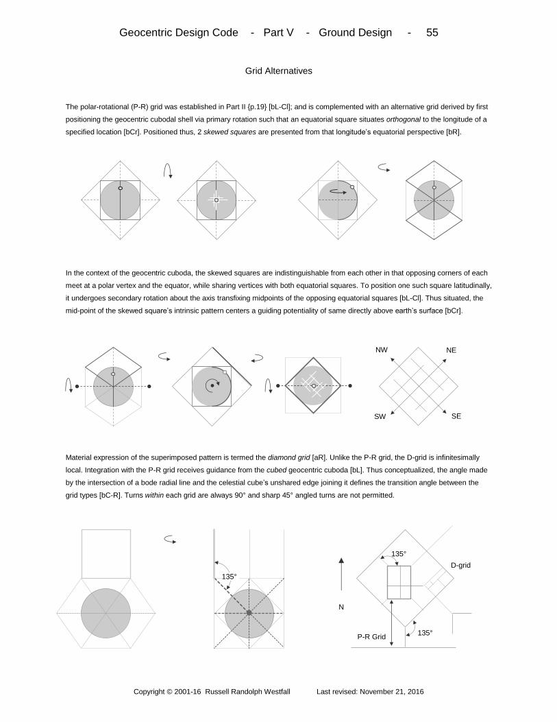
Geocentric Design Code - Part V - Ground Design - 55
Copyright © 2001-16 Russell Randolph Westfall Last revised: November 21, 2016
Grid Alternatives
The polar-rotational (P-R) grid was established in Part II p.19 [bL-Cl]; and is complemented with an alternative grid derived by first
positioning the geocentric cubodal shell via primary rotation such that an equatorial square situates orthogonal to the longitude of a
specified location [bCr]. Positioned thus, 2 skewed squares are presented from that longitude’s equatorial perspective [bR].
In the context of the geocentric cuboda, the skewed squares are indistinguishable from each other in that opposing corners of each
meet at a polar vertex and the equator, while sharing vertices with both equatorial squares. To position one such square latitudinally,
it undergoes secondary rotation about the axis transfixing midpoints of the opposing equatorial squares [bL-Cl]. Thus situated, the
mid-point of the skewed square’s intrinsic pattern centers a guiding potentiality of same directly above earth’s surface [bCr].
Material expression of the superimposed pattern is termed the diamond grid [aR]. Unlike the P-R grid, the D-grid is infinitesimally
local. Integration with the P-R grid receives guidance from the cubed geocentric cuboda [bL]. Thus conceptualized, the angle made
by the intersection of a bode radial line and the celestial cube’s unshared edge joining it defines the transition angle between the
grid types [bC-R]. Turns within each grid are always 90° and sharp 45° angled turns are not permitted.
NE NW
SW SE
N .06
135°
P-R Grid
D-grid
135°
135°

Geocentric Design Code - Part V - Ground Design - 56
Copyright © 2001-16 Russell Randolph Westfall Last revised: November 21, 2016
Bodal Prisms
In the context of grid alternatives’ superimpositions, customized topographic constructs are dimensionally completed via guidance
from the sloping elements of the 4 prime bode orientations aligned vertically relative to a specified location. Such localized bode
manifestations are referred to as bodal prisms, and the angles of their sloping lines and planes total 7 (aside from 0° and 90°).
Of the 7 prism angles, 30°, 45°, and 60° are exact while the remaining 4 are approximate with their precise ratios listed on page 13.
Angles 35°, 45°, and 55° manifest twice each via differing sloping elements from differing orientations - an attribute relevant to their
application. Within any given prism orientation, angles identified with steeper sloping elements than one of primary focus are termed
inherent angles [bL]. These play a major role in ground design, while shallower extra-terrestrial angles find use in Parts VI and VII.
To apply the angles of sloping elements, the bodal prism is generally regarded as an abstract entity analogous to the white light of
random terrain into a quantized set of constituent waveforms [aR]. More specifically, a prism angle is keyed to the unique point of a
wave’s curvature that is its maximum slope and that thus characterizes it with one number. Because this slope is located halfway
between trough and crest, a full wave is divided into quarters having maximum and 0° (horizontal) slope end points.
≈ 35° (triangle) 45° (square) ≈ 55° (square) ≈ 71° (triangle)
60° (edge)
30° (edge)
≈ 19° (triangle) ≈ 35° (square) ≈ 55° (triangle)
0
45° (edge)
Triangle-up Vertex -up
Square-up Edge-up
Maximum Slope (M)
= Hπ / 2L
Y
X
Y = M [1 + Cos (πx/L)] / π
H
L
Inherent
angle
Edge-up
Prism
slopes
Extra-
terrestrial
angle
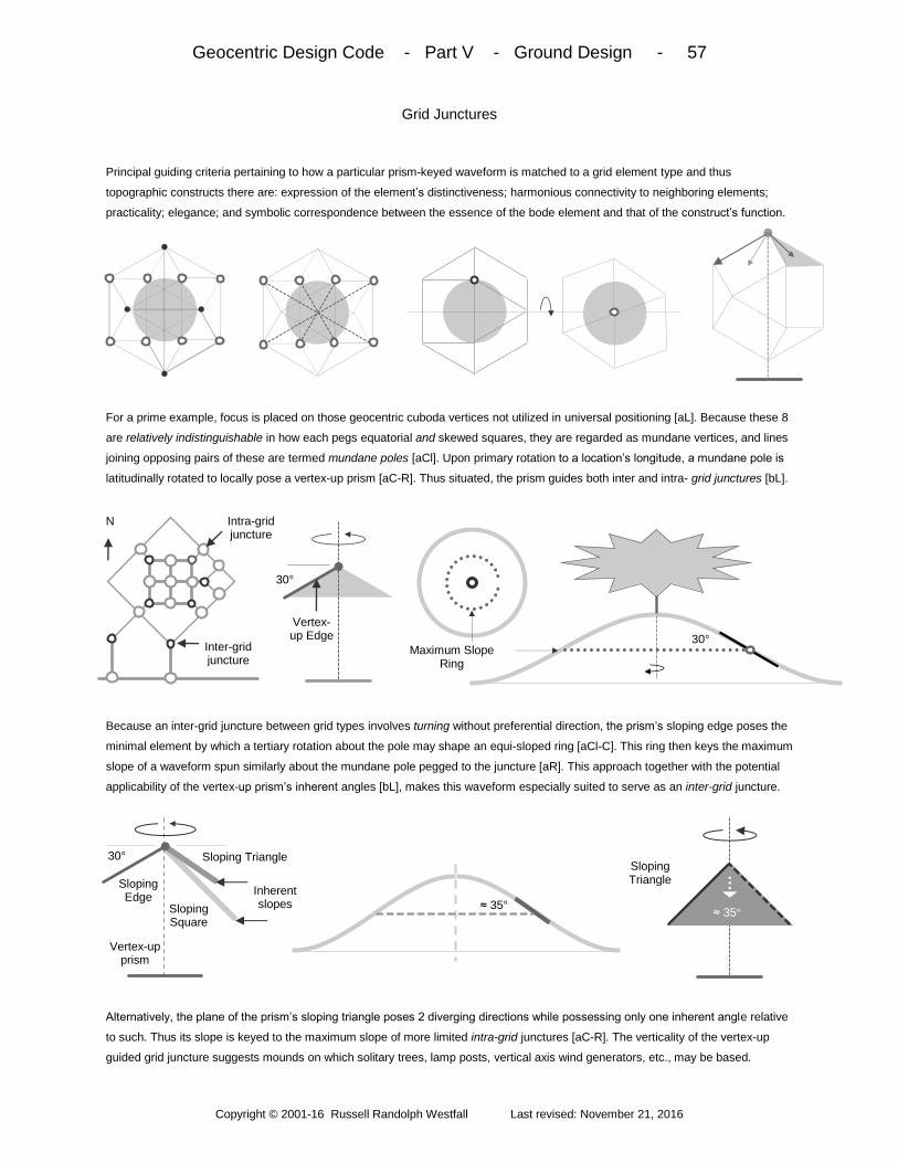
Geocentric Design Code - Part V - Ground Design - 57
Copyright © 2001-16 Russell Randolph Westfall Last revised: November 21, 2016
Grid Junctures
Principal guiding criteria pertaining to how a particular prism-keyed waveform is matched to a grid element type and thus
topographic constructs there are: expression of the element’s distinctiveness; harmonious connectivity to neighboring elements;
practicality; elegance; and symbolic correspondence between the essence of the bode element and that of the construct’s function.
For a prime example, focus is placed on those geocentric cuboda vertices not utilized in universal positioning [aL]. Because these 8
are relatively indistinguishable in how each pegs equatorial and skewed squares, they are regarded as mundane vertices, and lines
joining opposing pairs of these are termed mundane poles [aCl]. Upon primary rotation to a location’s longitude, a mundane pole is
latitudinally rotated to locally pose a vertex-up prism [aC-R]. Thus situated, the prism guides both inter and intra- grid junctures [bL].
Because an inter-grid juncture between grid types involves turning without preferential direction, the prism’s sloping edge poses the
minimal element by which a tertiary rotation about the pole may shape an equi-sloped ring [aCl-C]. This ring then keys the maximum
slope of a waveform spun similarly about the mundane pole pegged to the juncture [aR]. This approach together with the potential
applicability of the vertex-up prism’s inherent angles [bL], makes this waveform especially suited to serve as an inter-grid juncture.
Alternatively, the plane of the prism’s sloping triangle poses 2 diverging directions while possessing only one inherent angle relative
to such. Thus its slope is keyed to the maximum slope of more limited intra-grid junctures [aC-R]. The verticality of the vertex-up
guided grid juncture suggests mounds on which solitary trees, lamp posts, vertical axis wind generators, etc., may be based.
Inter-grid juncture
N
30°
Maximum Slope Ring
30°
Intra-grid juncture
Vertex-up Edge
Inherent slopes ≈ 35° Sloping
Square
Sloping Triangle
≈ 35°
Sloping Edge
Vertex-up prism
30° Sloping Triangle

Geocentric Design Code - Part V - Ground Design - 58
Copyright © 2001-16 Russell Randolph Westfall Last revised: November 21, 2016
CBA Embanking
Integration of the code’s prime architectural style with the earth first requires selection of the square-up prism by virtue of this
element’s role in the CBA foundation [bL-Cl]. Thus assigned, the prism is centered on a CBA corner where focus is placed on the
prism’s (45°) sloping edges - the minimal elements of sweep about a corner aligned-axis [bC].
To align the sloping edges to the orientation of the CBA foundation, the prism is rotated 45° in the plane of the grid [aCr-R]. Thus
oriented, 3 of the prism’s square pyramid triangles surround the corner precisely. Because the corner presents a vertical line and the
like-oriented vertex-up prism possesses 45° sloping squares, that prism is brought into play to afford extension of those planes
along both walls [bL-Cr]. Lines supplied by the square-up prism’s inherent 55° triangles vertically bound the squares’ skew [bR].
To laterally bound the plane, the square-up prism’s 45° sloping edges are utilized. Thus the 2 prisms work together, with the angle
common to both defining the default maximum slope of CBA embanking waveforms. In the context of CBA roof variability, the slope
poses a universal average at each and all latitudes. The slope also matches the inherent 45° angle of both grid juncture types for
fusion applicability. Aside from complementing CBA angularity, such embanking passively contributes to temperature moderation.
Wall Plane Direction
45° sloping Square
0
CBA Corner
45° Sloping
Vertex-up Squares
55° sloping inherent triangle line
45° Sloping
Square-up Edge
0
Square-up Prism
CBA Corner
45° sloping Edges
0
55°
0 Square-up
Prism
Top View Top View
CBA Corner
CBA Corner
45° 45°
45°

Geocentric Design Code - Part V - Ground Design - 59
Copyright © 2001-16 Russell Randolph Westfall Last revised: November 21, 2016
P-R Grid Berming
To shape waveforms apart from the abode and extended along polar-rotational grid lines, the edge-up prism is utilized by reason of
the grid’s essential linearity [bL]. Because of this grid type’s dualistic nature, the prism is aligned to the grid in 2 ways: Upon
longitudinally positioning an equatorial square, rotational edges undergo secondary rotation for latitudinal locating [bCl-C].
Upon directly positioning a polar edge longitudinally, it is latitudinally positioned via secondary rotation about the opposing mid-
triangle equatorial axis [aCr-R]. With either path, the edge-up prism poses a sloping square that is keyed to the maximum slope of
waveforms extended along grid lines to form berms [bL-Cl]. The sloping square’s angle represents the fusion formula solution to the
default CBA embanking slope. The 35° sloping triangle required for the fusing element is supplied by the vertex-up prism [bCr].
The vertex-up prism also functions to round the end of the berm via tertiary rotation about its innate vertical axis [aR], while its
sloping triangle may also fuse to the inherent 45° sloping squares of both inter- or intra- grid junctures [bL-Cl]. The vertex-up prism’s
vertical axis, together with the square/triangle transformation arcs it superimposes on the edge-up prism’s squares, attunes the
berm to plant growth in settings ranging from residential landscaping to farm field crop furrows [bCr-R].
30° Inter-grid Juncture 35° Intra-grid Juncture
45° 45°
≈ 35°
≈ 35° Waveform Cross-
section
Sin-1
[(√3/3) Tan 45°] ≈ 35°
P-R grid berm profile
0
Top View
≈ 35°
Edge-up Prism Vertex-up
Prism
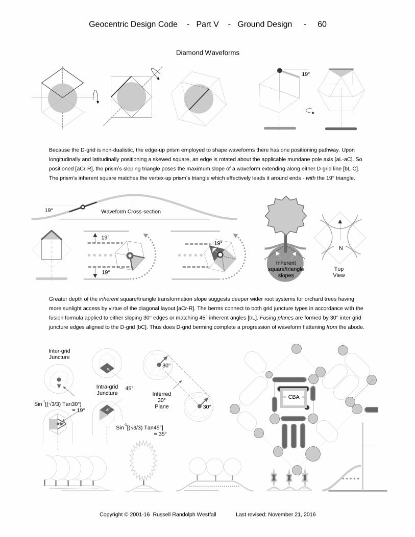
Geocentric Design Code - Part V - Ground Design - 60
Copyright © 2001-16 Russell Randolph Westfall Last revised: November 21, 2016
Diamond Waveforms
Because the D-grid is non-dualistic, the edge-up prism employed to shape waveforms there has one positioning pathway. Upon
longitudinally and latitudinally positioning a skewed square, an edge is rotated about the applicable mundane pole axis [aL-aC]. So
positioned [aCr-R], the prism’s sloping triangle poses the maximum slope of a waveform extending along either D-grid line [bL-C].
The prism’s inherent square matches the vertex-up prism’s triangle which effectively leads it around ends - with the 19° triangle.
Greater depth of the inherent square/triangle transformation slope suggests deeper wider root systems for orchard trees having
more sunlight access by virtue of the diagonal layout [aCr-R]. The berms connect to both grid juncture types in accordance with the
fusion formula applied to either sloping 30° edges or matching 45° inherent angles [bL]. Fusing planes are formed by 30° inter-grid
juncture edges aligned to the D-grid [bC]. Thus does D-grid berming complete a progression of waveform flattening from the abode.
19°
19° Waveform Cross-section
0
N 19°
19°
19° Top View
Inherent square/triangle
slopes
Sin-1[(√3/3) Tan30°]
≈ 19°
Inferred 30°
Plane
45°
30°
30°
Intra-grid Juncture
Sin-1[(√3/3) Tan45°]
≈ 35°
Inter-grid Juncture
CBA

Geocentric Design Code - Part V - Ground Design - 61
Copyright © 2001-16 Russell Randolph Westfall Last revised: November 21, 2016
Topographic Variations
Options pertaining to wave-formed mounds, berms, and architectural embankments fall into 2 categories. To afford areal flexibility
and expand planting applicability, terracing generally entails setting the trough of one waveform atop the crest of another. The two
waveforms typically have the same slope (exceptions are required in Part VII), but they may scale to any size relative to each other.
The 0° juncture between waveforms may be extended laterally, and as the maximum slope also poses a natural juncture, it too may
be separated to accommodate desired planting needs. Because 1/4 waves possess the essentials of maximum and 0° slopes, they
may be used alone or in reverse order. At the top, mounds may be spun around a ring to form circular plateaus. The other category
of options pertain to merging waveforms with the natural terrain such that each sets off the virtues of the other with a clean juncture.
Like CBA walls, the simplest, most stark interfaces are posed by vertical drops from the circular (and grid-aligned bases) of mounds
(and berms). Another option characterized by a defined juncture extends the maximum slope straight to the terrain - with the lower
areas of mound or berm ends essentially becoming truncated conical forms. Flat horizontal interfaces are detailed on Page 12.
Maximum slope
Truncated Cone
Truncated Cone
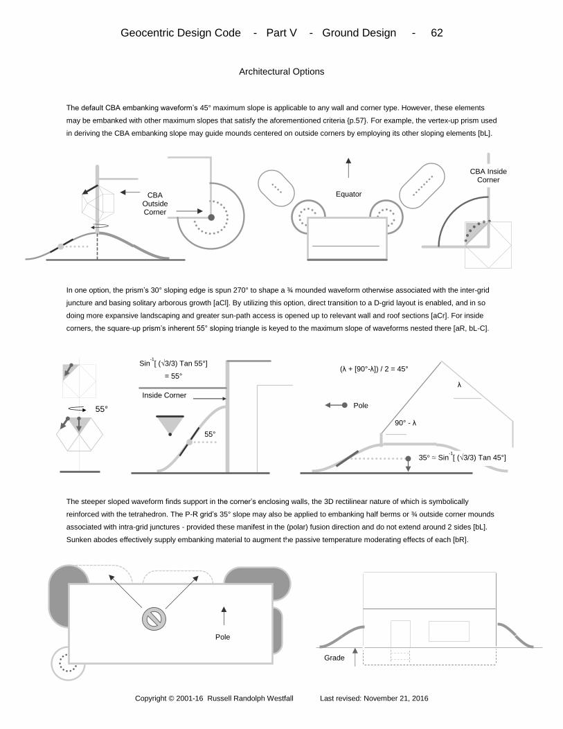
Geocentric Design Code - Part V - Ground Design - 62
Copyright © 2001-16 Russell Randolph Westfall Last revised: November 21, 2016
Architectural Options
The default CBA embanking waveform’s 45° maximum slope is applicable to any wall and corner type. However, these elements
may be embanked with other maximum slopes that satisfy the aforementioned criteria p.57. For example, the vertex-up prism used
in deriving the CBA embanking slope may guide mounds centered on outside corners by employing its other sloping elements [bL].
In one option, the prism’s 30° sloping edge is spun 270° to shape a ¾ mounded waveform otherwise associated with the inter-grid
juncture and basing solitary arborous growth [aCl]. By utilizing this option, direct transition to a D-grid layout is enabled, and in so
doing more expansive landscaping and greater sun-path access is opened up to relevant wall and roof sections [aCr]. For inside
corners, the square-up prism’s inherent 55° sloping triangle is keyed to the maximum slope of waveforms nested there [aR, bL-C].
The steeper sloped waveform finds support in the corner’s enclosing walls, the 3D rectilinear nature of which is symbolically
reinforced with the tetrahedron. The P-R grid’s 35° slope may also be applied to embanking half berms or ¾ outside corner mounds
associated with intra-grid junctures - provided these manifest in the (polar) fusion direction and do not extend around 2 sides [bL].
Sunken abodes effectively supply embanking material to augment the passive temperature moderating effects of each [bR].
CBA Inside Corner
CBA Outside Corner
Equator
55°
Sin-1[ (√3/3) Tan 55°]
= 55° (λ + [90°-λ]) / 2 = 45°
90° - λ
λ
35° ≈ Sin-1[ (√3/3) Tan 45°]
Pole 55°
Inside Corner
Pole
Grade
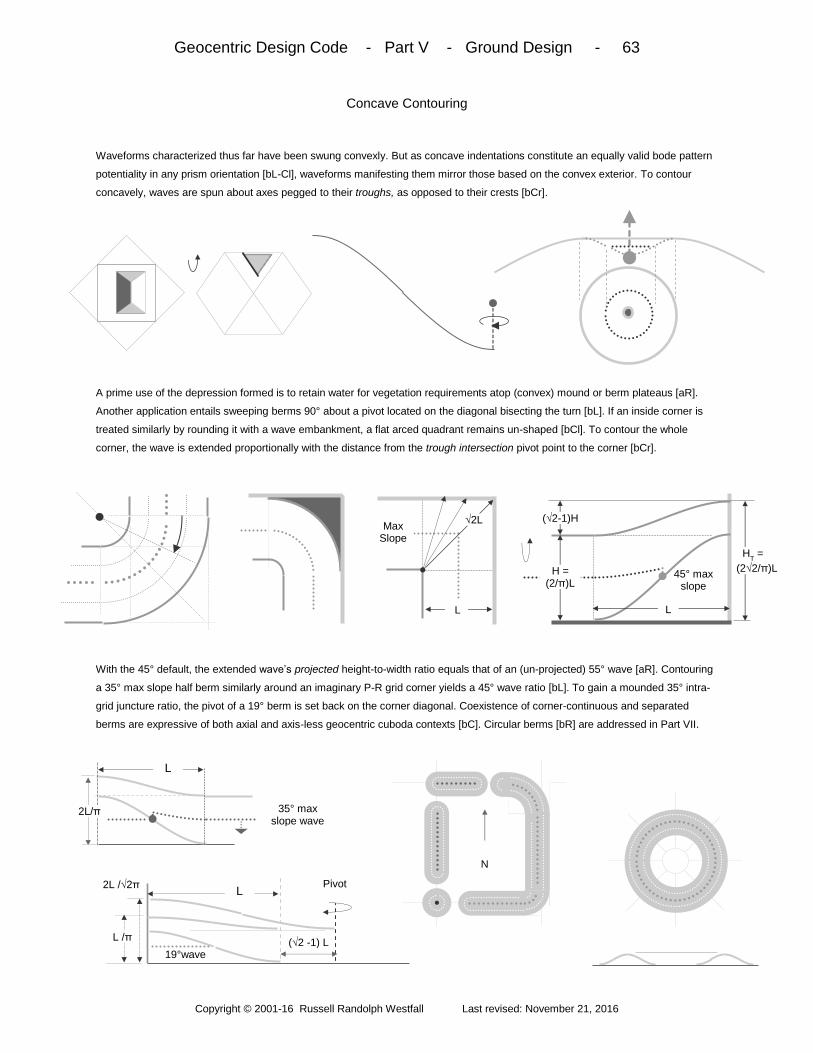
Geocentric Design Code - Part V - Ground Design - 63
Copyright © 2001-16 Russell Randolph Westfall Last revised: November 21, 2016
Concave Contouring
Waveforms characterized thus far have been swung convexly. But as concave indentations constitute an equally valid bode pattern
potentiality in any prism orientation [bL-Cl], waveforms manifesting them mirror those based on the convex exterior. To contour
concavely, waves are spun about axes pegged to their troughs, as opposed to their crests [bCr].
A prime use of the depression formed is to retain water for vegetation requirements atop (convex) mound or berm plateaus [aR].
Another application entails sweeping berms 90° about a pivot located on the diagonal bisecting the turn [bL]. If an inside corner is
treated similarly by rounding it with a wave embankment, a flat arced quadrant remains un-shaped [bCl]. To contour the whole
corner, the wave is extended proportionally with the distance from the trough intersection pivot point to the corner [bCr].
With the 45° default, the extended wave’s projected height-to-width ratio equals that of an (un-projected) 55° wave [aR]. Contouring
a 35° max slope half berm similarly around an imaginary P-R grid corner yields a 45° wave ratio [bL]. To gain a mounded 35° intra-
grid juncture ratio, the pivot of a 19° berm is set back on the corner diagonal. Coexistence of corner-continuous and separated
berms are expressive of both axial and axis-less geocentric cuboda contexts [bC]. Circular berms [bR] are addressed in Part VII.
L
√2L
H = (2/π)L
45° max slope
L
HT =
(2√2/π)L
(√2-1)H Max
Slope
N
35° max slope wave
2L/π
19°wave (√2 -1) L
2L /√2π L
Pivot
L /π
L
0

Geocentric Design Code - Part V - Ground Design - 64
Copyright © 2001-16 Russell Randolph Westfall Last revised: November 21, 2016
Outdoor Rooms
To complement abode compactness, CBA geometry is readily extended to outside living areas featuring the preceding concepts.
With courtyards, waveforms embanking full or partial height inward-facing walls mirror the default 45° maximum slope of outward-
facing CBA walls. Inside corners may be swept concavely by such, or occupied by 55° quarter mounds [bL-R].
Courtyard and CBA wall embanking are linked tetrahedrally. If part of a larger scheme, outer-facing courtyard walls are guided by
the defaults, options, and rules of CBA walls. In cross-section, 35° max-sloped waveforms match the inner wall’s 45° waveforms
with their inherent slope while complementing 55° courtyard waveforms - be they manifest or inherent. With embanking or isolated
waveforms, seating is incorporated by sectioning vertically along the lines and circular arcs of maximum slopes [bL-Cr].
Seating boundaries must align to relevant grid lines. For areal partitioning, half berms may be swung concavely around imaginary
intersections to form cross, L, U, or T-shaped waveforms [aR]. Verticality imbued by vertex-up prisms’ participation in waveform
building attunes to posts supporting overhead lattices isolated from, or connected to, CBA structure [bL-bCl]. Other options expand
intra-grid mound quadrants to form a rectilinear plateau; and prism slopes key to stepped, quarter-section wading pools [bCr-R].
CBS Abode
Courtyard Tetrahedral Link
35° 45°
45° 55°
55°
N
Maximum Slope
35°
Grade
“Beach”
Lawn

Geocentric Design Code - Part V - Ground Design - 65
Copyright © 2001-16 Russell Randolph Westfall Last revised: November 21, 2016
Flat Grading
To contour horizontal surfaces, differing interpretations of “flat” may be engaged. Floors and waveform bases are referenced to
natural flat which corresponds to what gravity-based leveling instruments would indicate [bL-C]. Natural flat around and between
structures and grid constructs unifies them while posing a clean interface to natural terrain or freeform non-code contouring [bCr].
Use of natural flat is limited because of water drainage problems it poses. Limited drainage is attained by utilizing the abstract flat
applied to CBA roof extensions p.22. This plane slopes downward toward the equator at an angle corresponding to the latitude-
dependent deviation of the real oblate earth from an ideal sphere [aR]. Rifts between natural and abstract flats are smoothed with
freeform contouring. A more universal isotropic flat contouring approach is also derived from ideal and oblate earth spheres [bL-C].
Upon matching flat plane cross-sections of real and ideal spheres via rotations about either of the 2 pertinent orthogonal axes, the
angle rotated through defines the maximum slope of waveforms in all directions. Another flat derives from the mid-edge axis rotation
that directly aligns the natural triangle’s leading edge common the abstract square [aR], and only applies to extended ridges. At
corners [bL], wave size is held constant by shifting termini along diagonal ridges exemplified in the terracing scheme [bR].
Natural Flat
λ
Gravity
Equator
λ - Tan-1(.99345 Tan λ)
= Δ
Natural Flat
Abstract Flat
Freeform Contouring
Cos-1(7900/7926) ≈ 4.6°
30° ≈ 28.1°
Tan-1 (√14) / 7
≈ 1.9°
≈ 1.9°
Max slope Contour
Horizontal wave crest
ridge
Equal-length Waveforms
Natural flat
Freeform Contouring
Natural Flat

Geocentric Design Code - Part V - Ground Design - 66
Copyright © 2001-16 Russell Randolph Westfall Last revised: November 21, 2016
Ground Formulas
Essential bode wave numbers tabulated above include the correspondence between the square of a waveform’s maximum slope
and the number of maximally-sized circles that may be nested into them [bL]. Beyond any symbolic significance, utilities or earth
tubes may be centered on such. To determine quantities of earth required to build mounds, berms, or embankments, a generalized
cross-section depicts basic quarter wave crests (C) and troughs (T), with their areas (A) applicable to straight section calculations.
Wave units are separated from generalized pivots points to include both convex (X) and concave (V) sweeps. Volumes are for full
360° rotations and thus halving or quartering may be required. Total volumes must include cylindrical, rectangular, and conical
contributions. General guidelines for proportioning the abode to its lot or landscaping layout range from a 3:1 minimum to a 8-to-1
maximum ratio to assure sufficient septic field area [bL-C]. In cities, a 1:1 courtyard ratio affords outdoor privacy [aR].
Bodal Prism Angles ≈ 19° 30° ≈ 35° 45° ≈ 55° 60° ≈ 71°
Maximum Slope Ratios 1 : 2√2 1 : √3 1 : √2 1 : 1 √2 : 1 √3 : 1 2√2 : 1
Height /Length Ratios 1 : √2π 2 : √3π 2 : √2π 2 : π 2√2 : π 2√3 : π 4√2 : π
Maximally Nested Circles # 1/8 1/3 1/2 1 2 3 8
CBA CBA
CBA
L
√2L
AC = (2 /π )H
CL
C A
T = (1- [2 /π ] )H
TL
T M = Hπ /2L V
CX = 4 (π–2) H
C L
C (L
C+2R
C X) /π ≈ 0.463 H
C L
C π (L
C+ 2R
C X)
VTX
= (3π2 - 4π - 8 ) H
T L
T (L
T+ 2R
T X) / 3π
≈ 0.305 H
T L
T π (L
T+ 2R
T X)
VCV
= 4(2+π )HC
LC
(LC
+2RC V
) / 3π ≈ 0.695 HC
LC
π (LC
+2RC V
)
VTV
= (π2 - 4π + 8 ) H
TL
T(L
T + 2R
T V) / π
≈ 0.537 H
T L
T π (L
T + 2R
TV) Cylinder V = 2πRH
Cylindrical Shell V = 2πH (R2
Outer – R2
Inner) Conical Section V = (2Mπ /3 )(R
Bottom – R
Top)3 Box V = H x L x D
AT
AC
HT
LT
HC
RTX
LC R
CX
M
RTV
RCV
Convex Concave
Y = M [1 + Cos (πx/L)] / π

Geocentric Design Code - Part VI - Wheel Extrapolations - 67
Copyright © 2001-16 Russell Randolph Westfall Last revised: November 21, 2016
The wheel interpretation of the code’s conceptual foundation is extended to embrace alternative architectural styles,
rolling infrastructure, and other realms of mobile artifacts that heavily employ integration techniques to incorporate a
range of functionalities such as propulsion and mechanical generation of electricity.
Overview: Part VI begins by applying guidance from both the celestial co-cube and the neutralized macrocosmic
wheel to guide polar aligned wheel-based abodes and diamond grid buildings suitable for commercial, industrial,
agricultural, and institutional as well as residential realms. Both structure types utilize the geometry of abstract path
upon which the wheel rolls, with its path manifestations shown to range from farm field furrows to roads and rails.
Path concepts attain their fullest expression in the design of grid-aligned code bridges, and in facilitating template
aircraft take-offs and landings, all terrestrial gaps are freely spanned. Then after exploring air flow surfaces needed
to get off the ground, transport template application is extended further to the water in the design of marine vessels.
To propel non-rolling artifacts, fluid dynamic cubodas are drawn from the inter-woven planes of the code’s base
form and further utilized in turbine applications. Finally, satellite design is framed by the bodal wheel aligned to its
disc orientation that, modified as directional discs, finds application with marine, air, and space craft.
Wheel-based Abodes - 68 - co-cube walls; h-shifted macrocosmic wheel; sloped squares; CBA annex; embanking
Diamond Grid Buildings - 69 - co-cube D-grid rotation; matching macrocosmic triangles; hip roof; stacking; clusters
Abstract Path - 70 - grid square to edge-up path; travel direction/traction; wheel/path resonance; path point fusions
Path Manifestations – 71 - farm field furrows; berm paralleling; side slopes; utilities and culverts; non-grid interfacing
Code Bridges - 72 - square-up roadways; cross-bracing; edge-up trusses and abutments; towers; parabolic arches
Template Aircraft - 73 - runways; template wing planes; wholistic angle of attack; HXP envelopment; wing options
Air Flow Surfaces - 74 - planform; parabolic airfoil; cylindrical design approach; ellipsoidal leads; bode wing planes
Marine Vessels - 75 - template hull; HXP decking; sealing; venting; masts; rounding; keels; cylindrical submersibles
Fluid Dynamic Cubodas - 76 - internal hexagons; propellers; blade patterns and curvatures; dynamic transformation
Turbine Applications - 77 - reaction turbine; hydroelectric dam geometry; impulse turbines; river and wind turbines
The Disc Orientation - 78 - co-planing bodal wheel; internal and external HXPs; satellites and orbits; disc curvatures
Directional Discs - 79 - bow lead construction; stern CBA constructs; orthogonal plane integration; docking schemes

Geocentric Design Code - Part VI - Wheel Extrapolations - 68
Copyright © 2001-16 Russell Randolph Westfall Last revised: November 21, 2016
Wheel-based Abodes
In addition to wheel ports and slots p.40, the macrocosmic wheel may guide dedicated polar-aligned architecture. To do so, the
wheel is rotated such that any central plane edge parallels the tangent of a specified location’s longitude [bL-Cl]. Thus positioned,
the wheel is hexagonally-shifted such that mirrored squares share the edge in the context of dynamic neutralization.
The matched squares’ slopes and 2D patterns are posed locally by the microcosmic wheel, and serve to guide roofs set on walls
framed generally by the co-cube projection P-II and aligned precisely to the local P-R grid [aC-Cr]. Because east and west walls
parallel the wheel’s central plane, circular vents and fenestration may be set into them [aR]. In addition to siding, stairs, etc., slopes
may be applied to longitudinally rounded roofs’ end tangents, and conical forms that round, or append to, polar ends [bL–C].
Another option entails separated and complementary CBA roof sections being set atop north and south wall annexes to frame
porches, sleeping-loft/baths, etc. [aR]. Embanking is characterized by 45° maximum slopes along north or south walls and with
WBA/CBA juncture mounds [bL]. East and west walls may host 19° berms to express wheel asymmetry, the more so if rounded with
35° half mounds. These and 30° corner mounds signify intra-and inter-grid junctures. Inside corners key to the wheel’s profile angle.
1:√2
≈ 35°
East-West
35°
E-W
35° Top View
N
35°
90°-ρ ρ
N - S
N-S
35°
19°
45°
45°
45°
45°
35°
30°
60° 35°
Top View
E-W
35° 19°
60°
60°
60°
North-South

Geocentric Design Code - Part VI - Wheel Extrapolations - 69
Copyright © 2001-16 Russell Randolph Westfall Last revised: November 21, 2016
Diamond Grid Buildings
D-grid architecture follows much of the positioning procedure used in crafting berms there. After locating a celestial co-cube
foundation square longitudinally and latitudinally via universal positioning [bL], the square is rotated about its mid-point axis to the D-
grid alignment. Thus situated, the cube atop the square generally guides walls and the general layout there [bCl-bC].
To guide roof design, the bodal shell (minus the cube) is rotated about the axis of relevant opposing vertices paralleling the edge of
the intended roof ridge [aCr]. With the edge located, the shell becomes a macrocosmic wheel which is h-shifted such that the edge
is shared by paired triangles [aR]. From the local microcosmic wheel representation [bL], the paired triangles guide the slope and
structure of hip style roofs set upon D-grid walls extending along NW-SE or NE-SW directions in essentially identical manners.
Ridge-aligned walls bear circular fenestration, while end planes are rectilinear and capped with √3:1 sloped roof sections. Vertical
stacking is centered evenly over the structure below it [bL-Cl]. With the clustering freedom enabled by corner mound fusing planes
p.60, application expands beyond residential use to commercial, institutional, agricultural and industrial realms [bC]. Embanking
corresponds to that of WBA, excepting 45° rounding of 35° berms and the use of extra-terrestrial angles [aR].
19° 1 : 2√2 ≈ 19°
NE – SW
or
NW - SE
30°
19°
30°
N
Macrocosmic Wheel
Celestial Cube
30° Inter- Grid juncture
Mounds
N
19°
35°
60° 30°
45°
35° 45°
E – W Or
N - S

Geocentric Design Code - Part VI - Wheel Extrapolations - 70
Copyright © 2001-16 Russell Randolph Westfall Last revised: November 21, 2016
Abstract Path
The geometry of that which the wheel rolls upon is first comprised of lines intrinsic to the square and that delineate the direction of
travel in either grid type [bL]. Tetrahedra that contribute to, and extend beneath, such lines are minimally expressed with inclusion of
complementary orthogonal lines signifying traction elements [bCl-bC]. A travel-directed line may also function as an axis.
About such axis, the tetrahedron (with host bode) is rotated to an edge-up position having a central, vertically-aligned plane [aCr].
Oppositely directed rotations on either side of a transversely extended path cross-section virtually superimpose a pair of h-shifts to
constitute a symmetric path potentiality [aR]. In profile, path mirrors the bodal wheel geometry to pose optimal economic strength
against deformation and minimize rolling friction - while grounding asymmetric dynamism in a continual periodic resonance [bL-C].
[
Path can also be regarded as the fusion of 2 points. A built-in fusion is suggested by the profile of path’s matching 19° sloped
triangles, with the hypothetical 30° plane fused to further evoking a vertex-up grid juncture [aR]. As the wheel rolls to its vertex-up
position, rotation about an extended instantaneous vertical axis brings inherent angles of both wheel and juncture into play [bL]. So
conceptualized, the 35° triangle adjoins the deeper 45° slope in what is regarded as a dynamic intra-grid juncture fusion [bCl-C].
The wheel’s vertex-up triangles match path’s edge-up sloping squares in a skating dynamic, with the pairing’s transformation arcs
evoking instantaneous areal traction [aCr]. The sloping square also hosts the edge-up tetrahedron’s orthogonal traction vectors to
mirror the slope made between transport template and HXP axle - in turn paralleling traction lines of path’s square-up origin [aR].
Orthogonal (Traction or
torsion element) Central
Hexagonal Plane
Line of Travel
Path Cross-section Tetrahedron
2
30°
f (30° ) =
Sin-1 [ (√3/3 ) tan30 ° ]
≈ 19°
2 1 1
Inter-grid juncture 30°
f(45°)
≈ 35°
35°
45°
30°
Intra-grid Juncture
35°
T-template
45°
35° ≈ 35°
Path Cross-section
≈ 35°
≈ 35°
HXP
≈ 35°
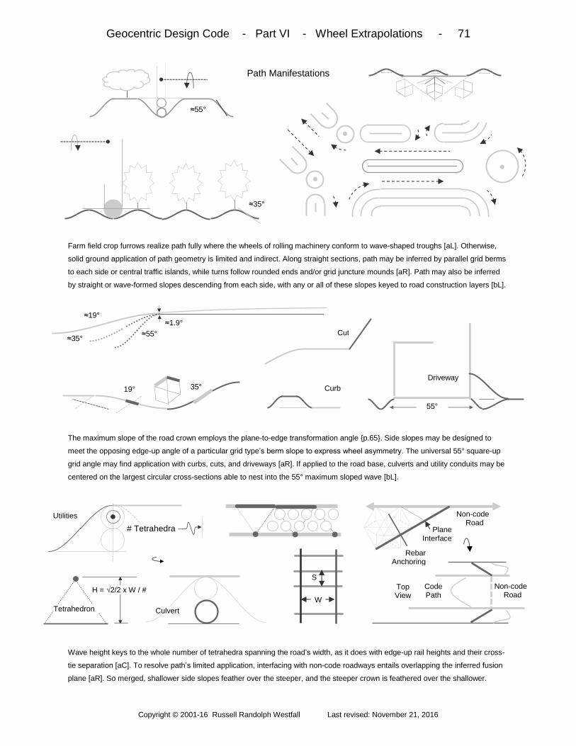
Geocentric Design Code - Part VI - Wheel Extrapolations - 71
Copyright © 2001-16 Russell Randolph Westfall Last revised: November 21, 2016
Path Manifestations
Farm field crop furrows realize path fully where the wheels of rolling machinery conform to wave-shaped troughs [aL]. Otherwise,
solid ground application of path geometry is limited and indirect. Along straight sections, path may be inferred by parallel grid berms
to each side or central traffic islands, while turns follow rounded ends and/or grid juncture mounds [aR]. Path may also be inferred
by straight or wave-formed slopes descending from each side, with any or all of these slopes keyed to road construction layers [bL].
The maximum slope of the road crown employs the plane-to-edge transformation angle p.65. Side slopes may be designed to
meet the opposing edge-up angle of a particular grid type’s berm slope to express wheel asymmetry. The universal 55° square-up
grid angle may find application with curbs, cuts, and driveways [aR]. If applied to the road base, culverts and utility conduits may be
centered on the largest circular cross-sections able to nest into the 55° maximum sloped wave [bL].
Wave height keys to the whole number of tetrahedra spanning the road’s width, as it does with edge-up rail heights and their cross-
tie separation [aC]. To resolve path’s limited application, interfacing with non-code roadways entails overlapping the inferred fusion
plane [aR]. So merged, shallower side slopes feather over the steeper, and the steeper crown is feathered over the shallower.
≈55°
≈35°
Culvert
Utilities
# Tetrahedra
Tetrahedron
H = √2/2 x W / #
Non-code Road
Rebar Anchoring
Plane Interface
Top View
Non-code Road
Code Path
W
S
≈19°
≈35° ≈55° ≈1.9°
35° 19°
Cut
Curb Driveway
55°

Geocentric Design Code - Part VI - Wheel Extrapolations - 72
Copyright © 2001-16 Russell Randolph Westfall Last revised: November 21, 2016
Code Bridges
Abstract path may be fully engaged by bridges aligned to either grid type. Square-up bode geometry defines roadway structure, with
essential tetrahedral lines corresponding to travel and traction, and lines connecting them contributing to shear and sway bracing
[bL- bCl]. Such roadways may situate anywhere between the top and bottom members of edge-up hexagonal truss geometry [bCr].
Further bracing is guided by lines joining the edge-up bode’s vertical planes [aR, bL]. Where bracing struts join truss members of
opposing sides or abutments varies with road width [bCl]. Flexibility in bracing placement is gained via extended floor beams or
vertical members introduced by reason of path’s vertex-up grid juncture potentiality [bCr]. Cylindrical linking intermediaries may join
square, edge, and vertex-up members along travel-aligned planar intersections [bR]. Otherwise, semi-circular plates serve as links.
Such linking is required extensively on towers structured with square-up octahedral stacking - joined by vertex-up verticals and
braced with edge-up geometry to infer intra-grid junctures [bL]. Towers support circular arches terminating at 30°, 60° or 90° angles,
or parabolas sectioned by edge-up planes terminating at 30° or 60° tangents [bL], with 15°, 35°, 45°, 55° and 75° angles reflecting
bode angles and verticals reflected anywhere along the curvature. Verticals outside the parabola terminate at the directrix [bC].
Top View
Cross-section
Square-up bracing
Roadway
Directrix
35° L:H = 4√3 : 3 Focal Distance = H/3
30°
60°
Focal Distance = 3H
L:H = 4√3 : 1 Square-up Compression
Vertex-up Tension
Edge-up Bracing
W Square-
to-edge-up
cylindrical Link
Circular plate
60° Abutment Profile
Truss
(2√6/6)W
Side Bracing
Floor Beam
(√6/6)W

Geocentric Design Code - Part VI - Wheel Extrapolations - 73
Copyright © 2001-16 Russell Randolph Westfall Last revised: November 21, 2016
Template Aircraft
To span terrestrial divides where code bridges are neither economic nor physically possible, alternative traveling modes guided by
the transport template may plausibly do so [bL]. Concerning aircraft, wings and stabilizers are guided by extended triangular planes
in top or bottom wing configurations having dihedral and anhedral slopes of +/- 19° [bL-Cl]. Either way, motion begins with rolling.
For the rolling dynamic, path geometry may be applied to the runway slab’s scoring and reinforcement. To impart a wholistic angle
of attack to the aircraft from template geometry, lowering an endpoint is attended by widening with the bottom wing configuration, or
vice versa for top wings [aR]. Hexagonal expansion portions of a design may be fully enveloped by template bode geometry [bL-Cl].
Where connecting struts do not meet bode or HXP vertices, contact point bracing follows intrinsically available intersecting lines.
Door and window openings may be linked in, or otherwise conform to plane patterns [aC]. Full circular rounding is allowed with
triangles. Wing planform (and axes for ailerons, flaps, elevators, etc.) draw from extended triangular planes [aCr]. Alternative wings
include a version of the bodal shift-based wing p.50 in which cylindrical linking centered on the root chord affords rotation [aR].
Other options extend the template’s rectilinear planes [bL-Cl], or employ the horizontally-oriented hexagonal extension [bCr-R].
Rebar Square-up
Tetrahedral spacing
Edge-up 60° scoring
Front Back
HXP
Top View
0° Dihedral
Fuselage
≈ 35°
Top View Fuselage
≈ 35°
HXT Planform
Fuselage
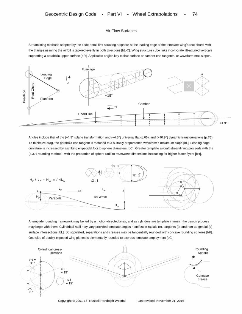
Geocentric Design Code - Part VI - Wheel Extrapolations - 74
Copyright © 2001-16 Russell Randolph Westfall Last revised: November 21, 2016
Air Flow Surfaces
Streamlining methods adopted by the code entail first situating a sphere at the leading edge of the template wing’s root chord, with
the triangle assuring the airfoil is tapered evenly in both directions [bL-C]. Wing structure cube links incorporate lift-attuned verticals
supporting a parabolic upper surface [bR]. Applicable angles key to that surface or camber end tangents, or waveform max slopes.
Angles include that of the (≈1.9°) plane transformation and (≈4.6°) universal flat p.65, and (≈10.9°) dynamic transformations p.76.
To minimize drag, the parabola end tangent is matched to a suitably proportioned waveform’s maximum slope [bL]. Leading edge
curvature is increased by ascribing ellipsoidal foci to sphere diameters [bC]. Greater template aircraft streamlining proceeds with the
p.37 rounding method - with the proportion of sphere radii to transverse dimensions increasing for higher faster flyers [bR].
A template rounding framework may be led by a motion-directed lines; and as cylinders are template intrinsic, the design process
may begin with them. Cylindrical radii may vary provided template angles manifest in radials (c), tangents (t), and non-tangential (s)
surface intersections [bL]. So stipulated, separations and creases may be tangentially rounded with concave rounding spheres [bR].
One side of doubly-exposed wing planes is elementarily rounded to express template employment [bC].
Leading Edge
≈19°
Chord line
≈1.9°
Root
Chord
Planform
Fu
sela
ge
Fuselage
Camber
1/4 Wave Parabola
LW
HW
HP
LP
HP
/ LP = H
W π / 4L
W
√2 : 1
√3 : 1
√2 : 1
Cylindrical cross-sections
Rounding Sphere
Concave crease
c-t ≈ 19°
c-s ≈ 35°
s-t ≈ 19°
c-c = 90°
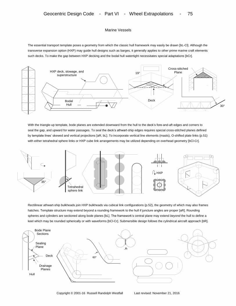
Geocentric Design Code - Part VI - Wheel Extrapolations - 75
Copyright © 2001-16 Russell Randolph Westfall Last revised: November 21, 2016
Marine Vessels
The essential transport template poses a geometry from which the classic hull framework may easily be drawn [bL-Cl]. Although the
transverse expansion option (HXP) may guide hull designs such as barges, it generally applies to other prime marine craft elements
such decks. To make the gap between HXP decking and the bodal hull watertight necessitates special adaptations [bCr].
With the triangle-up template, bode planes are extended downward from the hull to the deck’s fore-and-aft edges and corners to
seal the gap, and upward for water passages. To seal the deck’s athwart-ship edges requires special cross-stitched planes defined
by template lines’ skewed and vertical projections [aR, bL]. To incorporate vertical line elements (masts), O-shifted plate links p.51
with either tetrahedral sphere links or HXP cube link arrangements may be utilized depending on overhead geometry [bCl-Cr].
Rectilinear athwart-ship bulkheads join HXP bulkheads via cubical link configurations p.52, the geometry of which may also frames
hatches. Template structure may extend beyond a rounding framework to the hull if juncture angles are proper [aR]. Rounding
spheres and cylinders are sectioned along bode planes [bL]. The framework’s central plane may extend beyond the hull to define a
keel which may be rounded spherically or with waveforms [bCl-Cr]. Submersible design follows the cylindrical aircraft approach [bR].
Cross-stitched Plane
Deck
30°
Deck
19° HXP deck, stowage, and superstructure
Bodal Hull
35°
HXP
Tetrahedral sphere link
Bode Plane Sections
Sealing Plane
Drainage Planes
Deck
Hull
60°

Geocentric Design Code - Part VI - Wheel Extrapolations - 76
Copyright © 2001-16 Russell Randolph Westfall Last revised: November 21, 2016
Fluid Dynamic Cubodas
To move (or be moved by) fluids, the bodal wheel’s (4) internal hexagonal planes are engaged [aL]. For axial flow, propeller blades
may be drawn from the 3 skewed hexagonal patterns so as to cause flow in one direction upon rotation [aCl-Cr]. Paired triangles
may be rotated about their common edge axes to conform to the central hexagon [aR]. In so doing, a controllable pitch range is
defined [aR]. One blade edge viewed in profile signifies the maximum slope and thus ideal pitch of a wave-projected helix [bL-Cl].
Propeller (or impeller) elements may be shaped from the central hexagon in 2 basic ways [aCr], then rounded by innate circularity.
Elements may also be folded along pattern lines and rounded circularly or with quarter waveforms [aR], or elliptically formed and
centered on a common focus [bL]. More curvature options are derived from dynamic transformations in which initial (given) and
alignments sought are joined by rotation steps - with the total of angles spun through less than that of a static fusion [bCl-R].
For example, in transforming the bode from the edge-up transporter mode to that of a triangle-up propeller, total rotation is less than
70° in 3 rotation steps – in contrast to the one 90° re-orientation characterizing a simple static cube linking scheme. Conceptualized
thus, transformation angles are applied to a propeller element’s corresponding pattern-defined axis.
Tan-1[1/ (2√2)] ≈ 71°
≈ 55° rectilinear
≈ 71° hexagonal
30° - Tan
-1(√3/9)
≈ 19°
Tan-1(√6/6) ≈ 22°
Tan-1√(14)/7
≈ 28° √3:1
Tan-1(√3/9)
≈ 11°

Geocentric Design Code - Part VI - Wheel Extrapolations - 77
Copyright © 2001-16 Russell Randolph Westfall Last revised: November 21, 2016
Turbine Applications
Bodal wheel geometry is also applicable to reaction turbines, with axes oriented vertically in hydroelectric dams [bL]. In these
contexts, the triangle-up turbine framework situates atop cube link configurations interfacing a square-up oriented structure. With
such dams exhibiting bridge, berm, and marine craft attributes, they are also guided by orthogonal edge-up orientations [bCl].
Junctures between the dam wall and buttresses are joined by cube link configurations [aCr]. These may link to square-up bode
elements which guide cross reinforcement [aR, bL]. Square-up bode geometry swung about a cylindrical link that follows edge-up
horizontals poses an optional back slope. Impulse turbines fed by hexagonally-arrayed jets exhibit alternating bode-guided and
rounded cups [bCl-C]. Edge-up lines guide penstock slopes and wave-formed spillways that situate turbine chambers [bCr].
Fish ladder frameworks may also be framed from edge-up geometries. Aside from a dam’s grid-aligned course, it may be curved
convexly and concavely in the manner of berms to meet natural terrain [aR]. For run-of-the-river turbines, radial HXP planes are
applicable if the HXP is paired to negate the form’s symmetric neutralization [bL]. If applied to a vertical axis wind turbine, 2 or 3
planes are specified by bode-keyed curvatures [bCl-C]. One plane end may be twisted and keyed to a helix-projected wave [bCr-R].
60°
45°
19°, 35°
Buttress
Dam Face Rebar
45°
60°
Top View
55°
Tetrahedral Rebar
60°
HXP
Penstock
Spillway
HXP
HXP
60° = Tan-1(1/b)
b=√3/3
r = ae(√3/3)Θ
Logarithmic spiral 55°
Minimum slope
180° H =
√2ΠW /2 60° Quarter
waves
√3:1 half ellipses
W =
L S in(μ /2 )
μ = 60°, 120°, 180°
L

Geocentric Design Code - Part VI - Wheel Extrapolations - 78
Copyright © 2001-16 Russell Randolph Westfall Last revised: November 21, 2016
The Disc Orientation
The bodal wheel’s vertically-aligned axis suggests a free construct in which the wheel’s central bisecting hexagon parallels a surface
of travel. Co-planing surfaces include the water’s surface, subsea thermoclines, atmospheric layers, and iso-gravitational potentials.
So conceptualized, the disc’s 2 motions are translational along the surface and about the axis perpendicular to both plane surfaces.
The disc’s rotational aspect may be as minimal as being capable of readily changing direction 360° around the plane. Because the
disc is a rotating construct, it cannot undergo hexagonal-shifts and expansions as do transporter frameworks. HXP elements may
however be internally incorporated by h-shifting the bodal pattern at one axis end [bL]. Externally, short HXP elements may be
crafted in the manner of turbines, i.e., paired to retain overall asymmetry and dynamism [bCl].
Satellite design poses one prime application of the unmodified disc as its orientation optimizes rotational inertia for gyroscopic
control and stability [aCr-R]. Motion may coincide with the geocentric cuboda’s polar and subtropical orbital planes. The disc may
utilize various curvature options that manifest bode geometry [aL-R]. The slope of the line common to (triangle-up) bode planes keys
to conical and ellipsoidal forms which may draw from other proportions to express bodal asymmetry and vertical bias in hybrid forms
HXP
Bode
Geometry
H-shifted
Geometry Sub-tropical Orbit
Polar Orbit
≈ 55° Max slope
Tan- 1
(√6/ [3 -√3] ) ≈ 63°
a /b = √ (3 -√3)
a /b = 2+√3/ 2√ (1+√3)
≈ 55° ≈ 71°
Toroid

Geocentric Design Code - Part VI - Wheel Extrapolations - 79
Copyright © 2001-16 Russell Randolph Westfall Last revised: November 21, 2016
Directional Discs
The disc’s pattern may be extended to bias its translational motion in a preferred direction by first mirroring a bode square pyramid
to complete an octahedron [bL]. Next, the triangle of the octahedron adjoining the disc’s central hexagon is matched by that of a
tetrahedron to imbue the disc with a distinct vertex which essentially leads non-shuttling marine, air, or space craft [bC-R].
By engaging one square in this procedure, its opposite is distinguished in a manner analogous to the geocentric cuboda’s equatorial
squares. By this association, cubical constructs may extend from the stern square without linking [bL]. However, outer constructs
are capped with a bode-guided form. If inward, the construct merges with a properly-linked and axially-aligned cubical structure like
CBA architecture [bCl]. Integrating a motion-directed plane orthogonal to the co-planing surfaces entails a circular plate link [bCr].
With the resulting O-shifted and thus motion-aligned hexagon, a bodal shift p.50 hosts a cube-linking scheme. As tetrahedral links
bolster one side, an h-shifted edge-up bode is nested onto the other to supply lines and planes for keels, tail fins, or non-rotational
propulsion guidance [aR, bL]. To dock shuttling template-guided transporters, tetrahedral links on cubical extensions or cube links
on hexagonal extensions (or their caps) may be utilized [bCl-R]. Each of these extension types may also serve as conveyers.
Tetrahedral Link
H-shift
Top Stern square
Below stern triangles
Tetrahedral Link
HXT
HXT

Geocentric Design Code - Part VII - Extra-topographic Guidelines - 80
Copyright © 2001-16 Russell Randolph Westfall Last revised: November 21, 2016
The geometry of the code’s conceptual model - applied thus far to framing the design of shelter, transporters, their
integration as well as the greater fusion with the ground and various dynamic constructs spawned - concludes with
guidance for artifacts seen as projecting from the earth architecturally, electromagnetically, and independently.
Overview: Part VII begins by applying circularity abstracted from the grid context to the duel expressions of
foundation pads that combine rectilinear junctures with variously configured yet invariably circular cross-sectioned
structures. Then greater pad details pertaining to access, structure, and interior layouts set the stage for building
basics characterized by cylindrical walls and the spherical domes crowning them. Ellipsoids, cones and their intrinsic
sections pose a set of alternative roof forms that may stack with vertical waveforms to create code towers. The
bode geometry of such is next employed to model the essentials of wave transmission with the electrodynamic
cuboda from which classical and quantum potentialities are extended to bode oscillations. Then Field-encoded
spheres complete the model which also applies to the gravitational challenge and guidance of relevant constructs.
After the bode’s characteristic slopes are keyed to streamlining curvatures applied to engine and atmospheric path-
ways, Part VII concludes with lift-off into the cosmos via wholistic rocketry from the greater launch pad of earth.
Grid Context - 81 - grid centeredness; grid rings; concentric berms; cross-sections; straightaways; traffic circles
Foundation Pads - 82 - grid nodes; geocentric cylindrical projections; inner/outer pad realms; 24-point structural ring
Greater Pad Details - 83 - access points; vertical and conical slopes; concentric and polygonal partitioning; structure
Building Basics - 84 - exterior wall cylinders; bode orientation layouts; spherical dome; tangent rings; structural arcs
Alternative Roof Forms - 85 - toroid; cones; arches; hyperboloids, paraboloids, and ellipsoids; partitioning; skylights
Code Towers - 86 - parallel form rotation; vertical disc-interface stacking; bode cylindrical proportions; vertical waves
The Electrodynamic Cuboda - 87 - electrostatic model; opposing charges; dynamic magnetism; quantum parallels
Bode Oscillations - 88 - bode dipoles; pattern wave propagation; spherical field projections; octahedral orthogonality
Field-encoded Spheres - 89 - photonic octahedra; relational sphere vectors; wave geodesics; synchronous spheres
Gravitational Challenge - 90 – EM model relevance; G-surface; tri-up bode; matter wave body cylinder; HXP linking
Streamline Curvatures - 91 - tri-up slopes; de Laval waves; booster melding; fins and tail ends; hybrid nose cones
Wholistic Rocketry - 92 - crew ops and living; payload containers; rocket holder; pad venting; service structures
+
-
-
+

Geocentric Design Code - Part VII - Extra-topographic Guidelines - 81
Copyright © 2001-16 Russell Randolph Westfall Last revised: November 21, 2016
Grid Context
The detailed layouts of either grid type are easily configured to follow a centralized pattern [bL]. Alternatively, both grids laid out
together may do so in a radial manner whereby circular paths encompassing them are regarded as grid integrating rings [bCl]. Such
rings are comprised of up to eight 45° or four 90° arced sections separated by straight tangential sections of equal length [bCr].
Circular path may be manifested as concentrically arced berms situated on either, both, or between (traffic island) sides meeting
gridlines perpendicularly [aR]. Wave-formed berm cross-sections follow the guidance of grid juncture maximum slopes on the out-
ward facing side and the angle common to square and vertex-up prisms on the inner slope, with berm ends rounded by the steeper
angle [bL-Cl]. If supporting elevated path, tangential straightaways begin by rounding berms with path’s edge-up profile slope [bCr].
Because straightaways exhibit bridge attributes, edge and square-up orientations may be utilized to guide overpasses, transit stops,
etc. [aR, bL]. Outer lanes and ramps are keyed to the universal “flat” angle between ideal and real earths p.65. Where grid rings
shrink to traffic circles, berms arcs are constrained by minimal proportions to avoid 45° convergences [bCr]. Arc center-points peg to
vertical members arrayed octagonally or rectilinearly on key wave locations of the circle’s terraced grid juncture mound [bR].
60°
≈ 4.6° Max Slope
W
≥ πW
Top view ≈ 4.6°
N, NW, or
NE
45°
Arced Berms
Circular Path
60°
Outer Slope
30° 45° 45°
45° 60°
60°
Abutments
30°

Geocentric Design Code - Part VII - Extra-topographic Guidelines - 82
Copyright © 2001-16 Russell Randolph Westfall Last revised: November 21, 2016
Foundation Pads
Centralized nodes on which grid lines converge or terminate may also be occupied by mounded forms that are circumscribed by
path and centered by flat circular areas which support constructs having circular cross-sections [bL-C]. Such pads derive from
cylindrical joining of the geocentric cuboda’s innate scaled down spheres - radially aligned along the vertex-up position [bR].
Conceptualized thus, the intersection of the cylinder’s projection with earth’s surface delineates a circular disc. Spheres do not align
linearly in the other 3 bode orientations, but repeat regularly in a radial direction and thus cylinders enveloping them may also be
projected to circularly section earth’s surface [bL]. The greater pad is characterized by 2 realms in which each is manifested by at
least one slope expression spun 360° around the pad proper. The outer realm expresses a grid juncture [bC-R].
The inner realm’s slope(s) reflects the supported construct’s orientation and may proceed upward in a terraced fashion and/or
downward to a crater. Slopes are typically keyed to waves, but may also shape conical forms or their sections. To structure the pad,
its guiding circle is divided into 24 equidistant points that begin with the 8 grid directions, with points of the bodal shell triangles
positioned by the basic geocentric rotations such that one triangle point always coincides with a grid direction [bL-R].
0 ET
Pad
0
Earth
Circular Section
Cylindrical
Projection
0
Path
Mound
Bode Sphere
Cylinder
Edge- Up
Square- Up
Triangle- Up
Intra-grid Juncture (35°)
Inter-grid Juncture (30°)
Grid/construct Interface
Inner (ET Construct) Realm
0
Inner Slope
Outer Slope
Pad Proper
ET Construct Pad Proper

Geocentric Design Code - Part VII - Extra-topographic Guidelines - 83
Copyright © 2001-16 Russell Randolph Westfall Last revised: November 21, 2016
Greater Pad Details
To access the greater pad’s perimeter path, the structural ring is divided further by intersections of perpendiculars to its 24 radial
end-points to form an alternate set of 24 directions [bL-Cl]. Opposing alternate point pairs straddling grid directions thus mark gaps
between perimeter berm ends [bC]. Access through the outer pad entails omitting 90° sections centered on grid directions [bCr].
The omitted section extends from arcs of maximum slope or the crest wherefrom cylindrical sections descend vertically [aR, bL].
Alternatively, truncated conical forms may descend from the same arcs to afford cylindrical placement flexibility, or in so doing guide
stairways of cylindrical shell steps [bC]. The 48-point access ring also guides rectilinear, vertically-aligned planes sectioned from the
cylinders to accommodate doorways [bCr]. This approach generally applies to the concave curvature of the inner slope also [bR].
Inner access sections to pads supporting triangle-up guided constructs are cut from that orientation’s hexagonal pattern. If access
planes are part of hexagonal interior layouts, and outer realm door planes introduce rectilinear or octagonal interiors, cylindrical
walls must separate the 2 geometries. Otherwise these forms generally characterize interiors centered by utility shafts [bL-C]. Steps,
elevators, partitions, etc., are guided by the access ring, while structural members key to the 24-point foundational ring [bC-R].
15°
Grid Path
Pad Perimeter
Arced Berm
Perimeter Path
Pad Proper
Pad Access
Cross-section
Outer Slope Crest
Max Slope
Alternate point set
Access Set
Structural set
Cylindrical section
Outer
Maximum Slope Cone
Cone Max Slope
Access (Doorway)
planes Pad Proper
Inner slope
Cylindrical section
60° Cylindrical
section
Cylindrical section
Inner/Outer Realm Boundary
Outer Realm
Access Plane Steps
Concentric Steps Radial
Steps
Concentric Elevator
Central Elevator
Cylindrical Boundary
Wall
Outer Door Plane
Inner Door Plane
Pad
Outer Maximum Slope
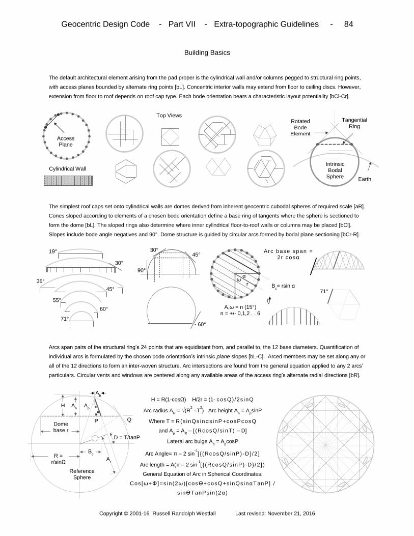
Geocentric Design Code - Part VII - Extra-topographic Guidelines - 84
Copyright © 2001-16 Russell Randolph Westfall Last revised: November 21, 2016
Building Basics
The default architectural element arising from the pad proper is the cylindrical wall and/or columns pegged to structural ring points,
with access planes bounded by alternate ring points [bL]. Concentric interior walls may extend from floor to ceiling discs. However,
extension from floor to roof depends on roof cap type. Each bode orientation bears a characteristic layout potentiality [bCl-Cr].
The simplest roof caps set onto cylindrical walls are domes derived from inherent geocentric cubodal spheres of required scale [aR].
Cones sloped according to elements of a chosen bode orientation define a base ring of tangents where the sphere is sectioned to
form the dome [bL]. The sloped rings also determine where inner cylindrical floor-to-roof walls or columns may be placed [bCl].
Slopes include bode angle negatives and 90°. Dome structure is guided by circular arcs formed by bodal plane sectioning [bCr-R].
Arcs span pairs of the structural ring’s 24 points that are equidistant from, and parallel to, the 12 base diameters. Quantification of
individual arcs is formulated by the chosen bode orientation’s intrinsic plane slopes [bL-C]. Arced members may be set along any or
all of the 12 directions to form an inter-woven structure. Arc intersections are found from the general equation applied to any 2 arcs’
particulars. Circular vents and windows are centered along any available areas of the access ring’s alternate radial directions [bR].
Earth
Intrinsic Bodal
Sphere Cylindrical Wall
Rotated Bode
Element (Cone)
Tangential Ring
Top Views
Access Plane
Q
Reference Sphere
P
Ap
Bc
Ah H
Ab
Dome base r
Ar
H = R(1-cosΩ) H/2r = (1- cosQ)/2s inQ
Arc radius AR = √(R
2 –T
2) Arc height A
h = A
psinP
Where T = R(s inQs inαs inP+cosPcosQ
and Ap = A
R – [ (RcosQ/s inT) – D]
Lateral arc bulge Ab = A
pcosP
Arc Angle= π – 2 sin-1[ (RcosQ/s inP) -D /2 ]
Arc length = A(π – 2 sin-1[ (RcosQ/s inP) -D / 2 ] )
General Equation of Arc in Spherical Coordinates:
Cos[ω+Φ ]=s in (2ω ) [ cosϴ+c osQ+s inQs inαTanP] /
s inϴTanPs in (2α )
R = r/sinΩ
D = T/tanP
Α,ω = n (15°) n = +/- 0,1,2 . . 6
30°
19°
35° 45°
55° 60°
71°
30° 45°
90°
- 60°
71°
Arc base span = 2r cosα
Bc= rsin α
α ω

Geocentric Design Code - Part VII - Extra-topographic Guidelines - 85
Copyright © 2001-16 Russell Randolph Westfall Last revised: November 21, 2016
Alternative Roof Forms
Intrinsic bode spheres situated (laterally) apart from the localized axis may be sectioned in the manner of domes and spun about
that axis to fashion toroidal forms set atop cylindrical shells [bL]. Cones shaped by bode slopes may be partitioned cylindrically with
concentric freedom [bCl-C]. Skylights are bounded by such partitions and radii centered on the access ring’s alternate 24 points.
Hyperbolic arches may span alternate ring points at the cone base, provided the bode orientation possesses vertical planes to
section them [aCr-R]. A hyperboloid dome is spun about the axis centered on the section of the cone that determines its asymptote,
and its base slope is specified to follow a shallower extra-terrestrial angle of the orientation employed [bL]. Paraboloidal domes are
formed by vertically sectioning bodal cones whose slopes parallel intrinsic vertical planes supplied by 3 of the 4 orientations [bCl].
Because parabolic proportion is independent of cone slope, a parabola is made code consistent by keying its base tangents to any
of a specified orientation’s angle set before being spun about its axes [aCr]. The parabola’s vertical reflection attribute enables floor-
to-ceiling cylindrical partitioning freedom [aR]. Ellipsoidal domes are defined by the horizontal projections of spheres sectioned from
bode planes [bL-C]. Such domes always feature vertical base tangents and are only partitioned at their foci [bCr].
Δ ≈19°, 30°, ≈ 35°, 45°, ≈ 55°, 60°, ≈ 71°
Q
Hyperbolic Section
Structure Column
Access Column
Latus Rectum @ f = a cosQ
Bisecting plane
Q b = a sinQ
Orientation Bisector [b/a]
Tr-up Tri [2(√2)/3 ≈ .94] Sq [√(2/3) ≈ .82] Eg-up Tri [1/3 = .333] Sq [(√3)/3 ≈.578]
Vx-up Tri [(√3)/3 ≈.578] Sq [√2 ≈ .71]
Sq-up Tri [√(2/3) ≈ .82]
a
Parabolic section Q
H = R(tanQ)/2
R
H
Generating Cone H =
R [ ( t an2Q)/ t anP] – a
Hyperboloid
P
Q = tan-1(a/b)
Cone
a
b

Geocentric Design Code - Part VII - Extra-topographic Guidelines - 86
Copyright © 2001-16 Russell Randolph Westfall Last revised: November 21, 2016
Code Towers
All forms generated from the bode’s intrinsic spheres or cones may be fashioned apart from a localized axis by reason of bode
pattern repetition [aL]. After such forms are spun about their own axes, they may be rotated about the parallel central axis to create
the flat circular planes that vertically bound them [aCr-R]. Such planes enable stacking configurations shaped according to an
orientation employed [bL]. Cylindrical spacing is determined by the ratio of an orientation’s vertically repeating spheres [bCl-Cr].
Because vertex-up directed spheres contact along a vertical line, enveloping cylinders may have any height-to-diameter ratio; and
as this orientation is invariably utilized in the greater foundation pads’ outer slopes, cylindrical walls of the inner realm’s construct
proportion freely up to a 1:1 ratio regardless of orientation [aR]. Beyond such, orientation ratios must be utilized [bL]. Vertical wave-
forms exhibit bode-keyed minimum slopes [bCl]. Quarter waves may situate up or down, or change scale in code towers [bC-R].
Paraboloid
Ellipsoid
Conical
Edge-up Stacking
Spherical
Vertex-up (1:1)
Enveloping Cylinder
Edge – up (√3:1)
Square -up (√2:1)
Triangle -up (√6:1)
60°
60°
19°
b/a = sin35°
Minimum slope
90°
≈71°
≈55° ≈ 71° ≈ 55°
≈ 35°
√6:1
√6:1
√6:1

Geocentric Design Code - Part VII - Extra-topographic Guidelines - 87
Copyright © 2001-16 Russell Randolph Westfall Last revised: November 21, 2016
The Electrodynamic Cuboda
The next 3 pages pose a model of electrodynamic behavior drawn from bode geometry. It begins by associating the symmetric array
of lines emanating from the bode center with electric field line vectors from a point charge at rest [bL]. Directionless electric field
potential is signified by the outer lines of planar intersections joining the (12) neighboring vector ends [bCl].
Imbalance in surrounding charge densities that generally give cause to charge motion is viewed as a pair of equal and oppositely-
oriented tetrahedra in which the point charge situates at their nexus [aCr-R]. The velocity vector attending the motion transfixes the
charge’s spherical representation to suggest an axis of rotation in the context of bode asymmetry [bL-bCl]. Thus relative direction is
imparted to orthogonal potential lines surrounding the charge motion, and magnetic field vectors (B) are attributed them [bCr].
Variation of B-field strength with velocity magnitude scales the bode [aR]. Inverse velocity scales the charge’s matter wavelength
signified by minimal line paths joining bode nodes along its motion [bL]. Tetrahedral edge paths model conductors in the quantum
mechanical diffraction slit sense, with the path viewed as the direct instantaneous E-field line joining an electrostatic dipole [bCl-Cr].
In its general motion, the point charge becomes identified with the tetrahedral plane and slows by the uncertainty principle [bR].
Volumetric Matter
Wave
v
Δx ~ h/Δv
Λ ~ h / v
B
E
Conducting
Paths
1/v
E-field vector (E)
- -
-
- -
+
+
+
+
+
-
-
Potential field (Φ)
Line (1 of 24) +
(√6)L/12 L
Tetrahedron (and charge
density) Center
+
-
v
B ~ v
Opposing Tetrahedra
Charge Sphere
Velocity Vector

Geocentric Design Code - Part VII - Extra-topographic Guidelines - 88
Copyright © 2001-16 Russell Randolph Westfall Last revised: November 21, 2016
Bode Oscillations
The abstract instantaneous dipole of a conducting tetrahedral charge path suggests that some formerly electrostatic potential lines
become E-field vectors [bL]. In the triangle-up dipole depicting the charge’s average motion, change of speed through a generalized
dielectric in concurrence with the uncertainty principle is caused by polarity switching via relative whole bode rotation [bCl-C].
As the charge slows, stops, and changes direction, field lines reverse accordingly [aCr-R]. To depict how oscillation effects the fields
surrounding it, a rope analogy is used with the impulse transmitted optimally along a field line orthogonal to the dynamic, and thus
propagation is directed along a former electrostatic E-vector [bL]. In extending the analogy to the bode structure around a stiffer rod,
the totality of the pattern is viewed akin to free space permittivity and permeability which determine the propagation speed limit.
The wave of the field pattern disturbance propagates in all directions favoring the orthogonal where periodicity spreads radially in
concentric waves at the speed of light [aR]. E and B vector projections onto the intrinsic sphere corresponding to wave concentricity
properly orthogonalizes the intersections of each with the propagation vector [bL-Cl]. Angles between the planes of E and B vectors
remain unchanged [bC]. Their proper orthogonality in the octahedral square implies a plane propagation vector [bCr-R].
B
E
E
B ~71° ~109°
B E
B
E
+
-
Φ → E
+
+
-
+
-
-
Time
(or Space)
Charge Oscillation
Bode Pattern
v = C
B Time
(or Space)

Geocentric Design Code - Part VII - Extra-topographic Guidelines - 89
Copyright © 2001-16 Russell Randolph Westfall Last revised: November 21, 2016
Field-encoded Spheres
The cross-product direction of the (half) octahedral square lines signifying orthogonal E and B field vectors suggests completing that
form by externally mirroring it [bL]. Alternative formation appends a full octahedron onto a tetrahedral face, in which case E and B
vectors intersect triangularly [bCl]. However generated, octahedra are enveloped by spheres contacting each form’s 6 points [bC].
So enveloping the form is analogous to centering a sphere on a relational point between neighboring spheres in the accretion
process that formed the bode [aCr]. However lines are matched to vectors in the 2 octahedral formation modes, projections onto
their enveloping spheres result in 60° to 90° and 90° to 180° transformations [aR]. Both are required to attain mutual orthogonality
with propagation vectors. Octahedral symmetry of field-encoded spheres translates to their being electromagnetically neutral [bL].
The octahedral sphere’s intrinsic centerlessness also signifies a mass-less entity having a relative radius of rp = √2 re which squared
doubles the charge’s spin angular momentum. Budding octahedral possess common lines in the bode’s radial vectors [aCl-C]. As
the bode expands by integral numbers, corresponding divisions project onto expanding spheres as geodesic field lines [aCr-R].
Spherical wave-fronts coincide with the light quanta of field encoded photons along the principle propagation paths below.
60°
90°
90°
180°
Octahedral Formation
E
B
Bode-centered wave-sphere
Geodesics
1
2
3
Scattering juncture
Bode-centered spherical
Wave-front
Field-encoded Spheres
Electron
√2re

Geocentric Design Code - Part VII - Extra-topographic Guidelines - 90
Copyright © 2001-16 Russell Randolph Westfall Last revised: November 21, 2016
Gravitational Challenge
The bode EM model also poses relevance to gravity with radial concentricity surrounding a sphere/point mass; field influence on
mass or massless energy densities; interchangeability of space and time; intrinsic relation between reference Euclidean and curved
space-time geometries; and the bode’s inherent ability to generate conic sections describing motion in a gravitational field [bL-Cr].
As the dipole model’s moving charge invariably possesses mass, the triangle directly confronted by such represents a gravitational
potential surface [aR]. Thus an anti-gravitational construct designed to transcend the surface while extending the momentum of the
dipole dynamic is guided by the triangle-up orientation [bL]. Such constitutes a 3rd wheel orientation after rolling and co-planing disc
manifestations. As an earth-ported construct, the rocket’s triangle has 2 geocentric cuboda positioning paths [bCr].
The rocket’s main cylindrical body is keyed to the repetition of innate vertically-aligned spheres and doubling such completes the
code-modeled matter wave [aC-Cr]. By integrals of such, the cylinder is partitioned by hexagonal expansions paired for rotational
capability [aR, bL]. Radial planes or their spheres may broach the main cylinder to guide design of control, stability, and boosting
components [bCl]. Cylinder sectioning with HXP planes affords smoother linking to vertex-up guided components [bCr-R].
Λ / 2
Λ
1
2√6
HXP Linking
Tri-up Linking
T
R
Erg Density Ellipse
Parabola Hyperbola
T
T
R
R

Geocentric Design Code - Part VII - Extra-topographic Guidelines - 91
Copyright © 2001-16 Russell Randolph Westfall Last revised: November 21, 2016
Streamline Curvatures
The steeper angles of the rocket’s guiding triangle-up framework optimize streamlining efforts [aL]. The angle made by the cone
generated from the edge common to the angled planes is included by reason of the rocket’s axial rotation dynamic [aC]. Internally,
angles are keyed to half waves that shape the engine’s de Laval nozzles [aR]. Wave scaling changes are made at rings of minimum
slope or at the throat [bL]. Nozzles may be one central and/or of 3 peripherals [bCl].
If merged with the main cylinder, their encasing cylinders are spherically melded. These and stabilizing fins are guided by HXP
geometry – including its intrinsic spheres [aC]. A simple approach to tail end rounding uses a reverse-oriented quarter wave [aCr].
With proper linking, vertically-aligned paraboloidal components may be generated [aR]. Monolithic nose cone design employs half
ellipsoids whose foci coincide with either full or half matter waves [bL].
Partitioning of such is limited to the latus rectum and focal sphere. Quarter and half waveforms allow cylindrical melding applicable
to multi-stage schemes [aCl]. To fashion hybrid nose cones, slopes are extended with conical forms, sectioned spheres, or cone-
generated HXP-sectioned hyperboloids [aCr]. A fusion of cone and nozzle design may find application with ducted rockets [aR].
~55°
≈71°
≈55° Quarter
wave
Conical
Sphere
Hyperbola √6D = Λ/2
(√7-√6)D
2√6D = Λ
Booster
≈55° ≈ 71°
≈ 63°
≈ 55° ≈ 71° Up Gas
Converging Passage
Diverging Passage
Concave Melding
V-up Cone-generated
Paraboloid
Central Cylinder
Stabilizer
Booster
~71°

Geocentric Design Code - Part VII - Extra-topographic Guidelines - 92
Copyright © 2001-16 Russell Randolph Westfall Last revised: November 21, 2016
Wholistic Rocketry
From the top down, a rocket’s hyperbolic cap housing the gyroscope sets on a sphere section from which 6 or 12 portholes are
sectioned and the slope is steepened. The truncated conical form below it houses the crew’s work stations accessed from the living
quarters shaped by an HXP-partitioned quarter wave which melds to a main cylindrical body of one matter wave length.
Payload containment utilizes the universal linking attributes of spheres or their cylindrical extensions for edge, square, or vertex-up
transport template-guided artifacts. Booster nose cones are keyed to the full matter wave ellipsoid. Encasing the lower rocket on the
ground is a dynamic break-away support stand that conforms to the inner launch pad and facilitates exhaust venting through the
outer pad. The flat ridge between outer and inner pad realms bases cylindrical shell service structures.
Alternatively, a cylindrical shell extended below the pad may contain a reservoir for buoyancy-assisted launches in which the rocket
stand is made watertight. Symbolic or otherwise, reasoned placement of one sphere nested into an aptly-scaled nose cone’s wave-
form - and lifted into the cosmos from the greater launch pad of earth - brings the code full circle to its foundational construction.
≈ 63°
≈ 55°
Operations Center
Sleeping
Utility/ Storage
Internal Payload
Links
Cylinder
Sphere
≈ 55°
Spherical Section
Payload Fuel Engines
Living
Wave-guided Exhaust Vent
Service Tower
Pad Access
≈ 55°
Outer Grid Juncture Mound
Vents
Rocket Stand
Reservoir
Service Towers
Ground Level
Launch Pad