Full duplex MAC 기술 -...
53
한국통신학회 차세대 초저지연/고효율 무선접속기술 워크샵 Full duplex MAC 기술 2016. 07. 14. Jae-Hyun Kim [email protected] Wireless Internet aNd Network Engineering Research Lab. http://winner.ajou.ac.kr School of Electrical and Computer Engineering Ajou University, Korea
-
Upload
trinhtuong -
Category
Documents
-
view
221 -
download
0
Transcript of Full duplex MAC 기술 -...
한국통신학회 차세대 초저지연/고효율 무선접속기술 워크샵
Full duplex MAC 기술
2016. 07. 14.
Jae-Hyun Kim
Wireless Internet aNd Network Engineering Research Lab.
http://winner.ajou.ac.kr
School of Electrical and Computer Engineering
Ajou University, Korea
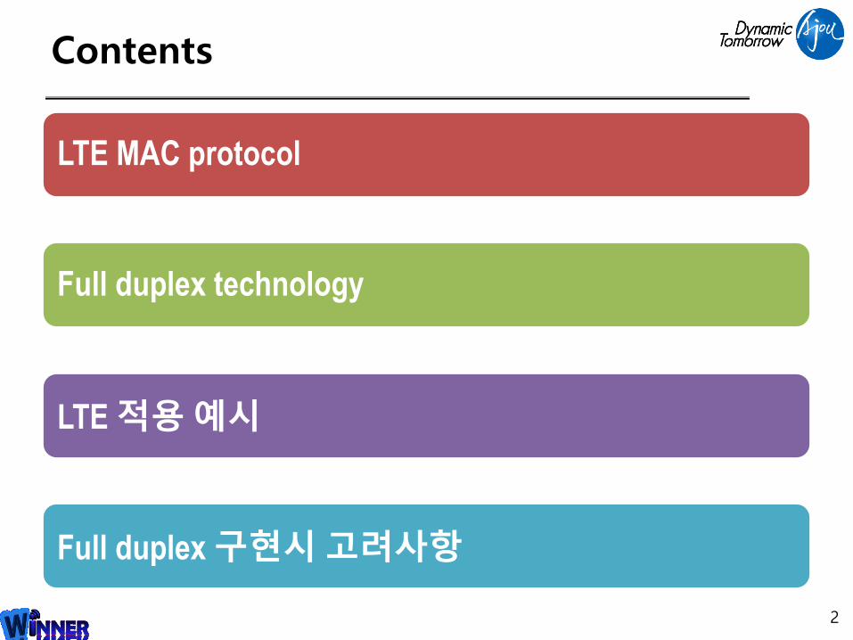
Contents
LTE MAC protocol
Full duplex technology
LTE 적용예시
Full duplex 구현시고려사항
2

LTE MAC protocol
3

Control Plane Protocol Overview
4
Non-access stratum PLMN selection
Tracking area update
Paging
Authentication
EPS bearer establishment, modification and release
• Access stratum control plane
– radio-specific functionalities
– The AS interacts with the NAS (upper layers)
RRC: Radio Resource Control PDCP: Packet Data Convergence Protocol
RLC: Radio Link Control PLMN: Public Land Mobile Network EPS: Evolved Packet System
eNB
PHY
UE
PHY
MAC
RLC
MAC
MME
RLC
NAS NAS
RRC RRC
PDCP PDCP
PHY
MAC
IP
S1-AP
SCTP
PHY
MAC
IP
S1-AP
SCTP
LTE-Uu(radio interface)
S1-MME(logical interface)
DRB Establishment : Signaling Radio Bearers
5
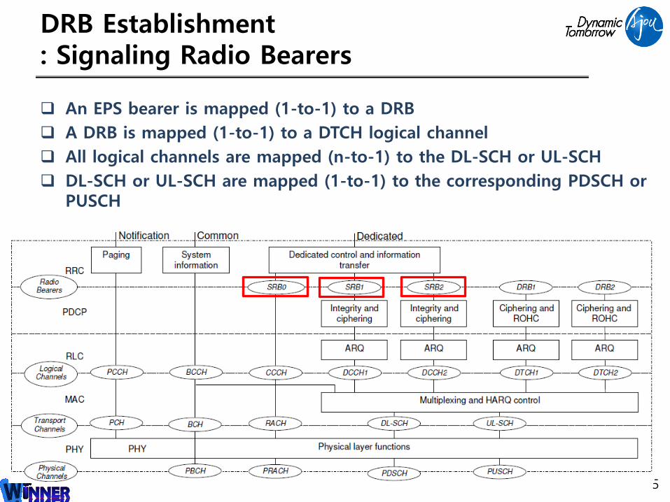
An EPS bearer is mapped (1-to-1) to a DRB
A DRB is mapped (1-to-1) to a DTCH logical channel
All logical channels are mapped (n-to-1) to the DL-SCH or UL-SCH
DL-SCH or UL-SCH are mapped (1-to-1) to the corresponding PDSCH or PUSCH
EPS Bearer Service Architecture
6
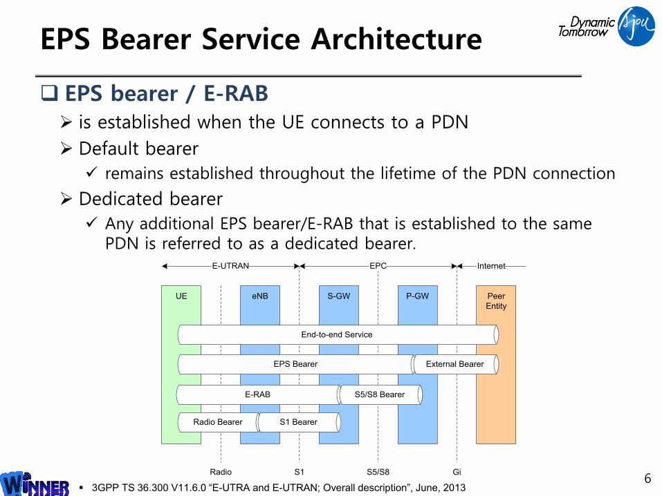
EPS bearer / E-RAB is established when the UE connects to a PDN
Default bearer
remains established throughout the lifetime of the PDN connection
Dedicated bearer
Any additional EPS bearer/E-RAB that is established to the same PDN is referred to as a dedicated bearer.
P-GWS-GW Peer
Entity
UE eNB
EPS Bearer
Radio Bearer S1 Bearer
End-to-end Service
External Bearer
Radio S5/S8
Internet
S1
E-UTRAN EPC
Gi
E-RAB S5/S8 Bearer
3GPP TS 36.300 V11.6.0 “E-UTRA and E-UTRAN; Overall description”, June, 2013
Summary of Control Plane
7
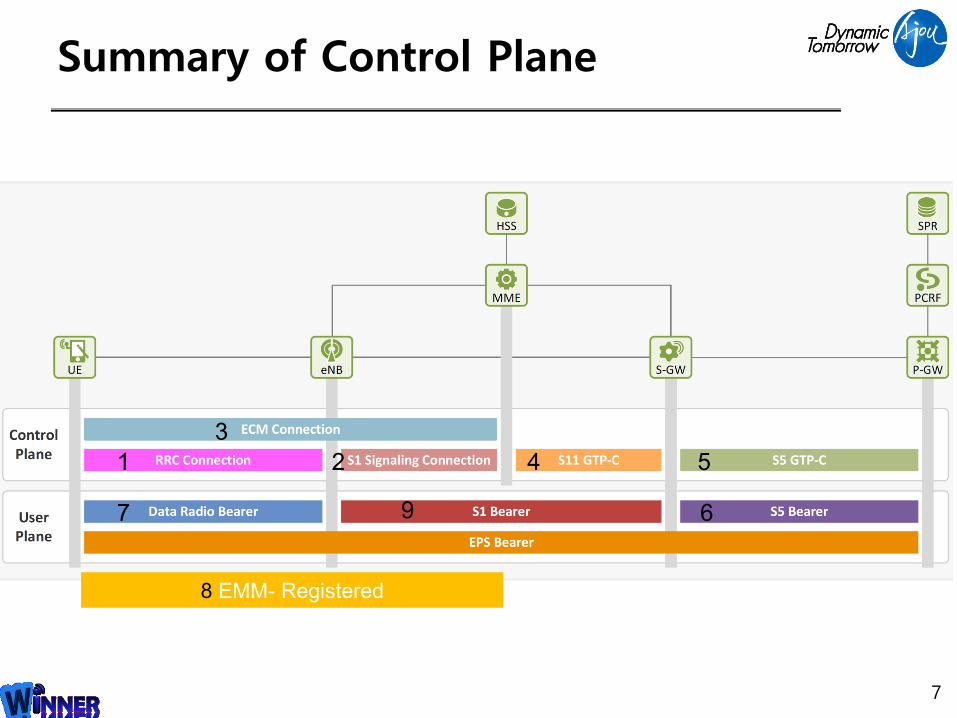
1
3
2 4 5
67 9
8 EMM- Registered
Overview of User Plane Protocol
8
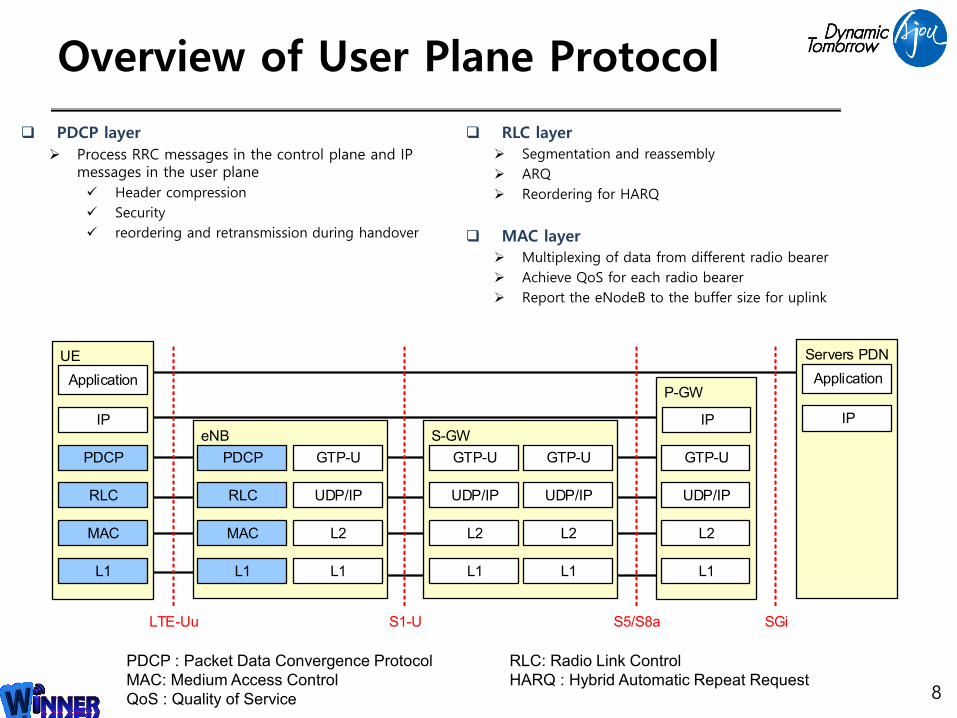
PDCP layer
Process RRC messages in the control plane and IP messages in the user plane
Header compression
Security
reordering and retransmission during handover
PDCP : Packet Data Convergence Protocol RLC: Radio Link Control
MAC: Medium Access Control HARQ : Hybrid Automatic Repeat Request
QoS : Quality of Service
RLC layer
Segmentation and reassembly
ARQ
Reordering for HARQ
MAC layer
Multiplexing of data from different radio bearer
Achieve QoS for each radio bearer
Report the eNodeB to the buffer size for uplink
S5/S8a
eNB
LTE-Uu
UE
Application
IP
PDCP
L1
MAC
RLC
S1-U
PDCP
L1
MAC
RLC
GTP-U
L1
L2
UDP/IP
S-GW
GTP-U
L1
L2
UDP/IP
GTP-U
L1
L2
UDP/IP
P-GW
IP
GTP-U
L1
L2
UDP/IP
SGi
Servers PDN
Application
IP
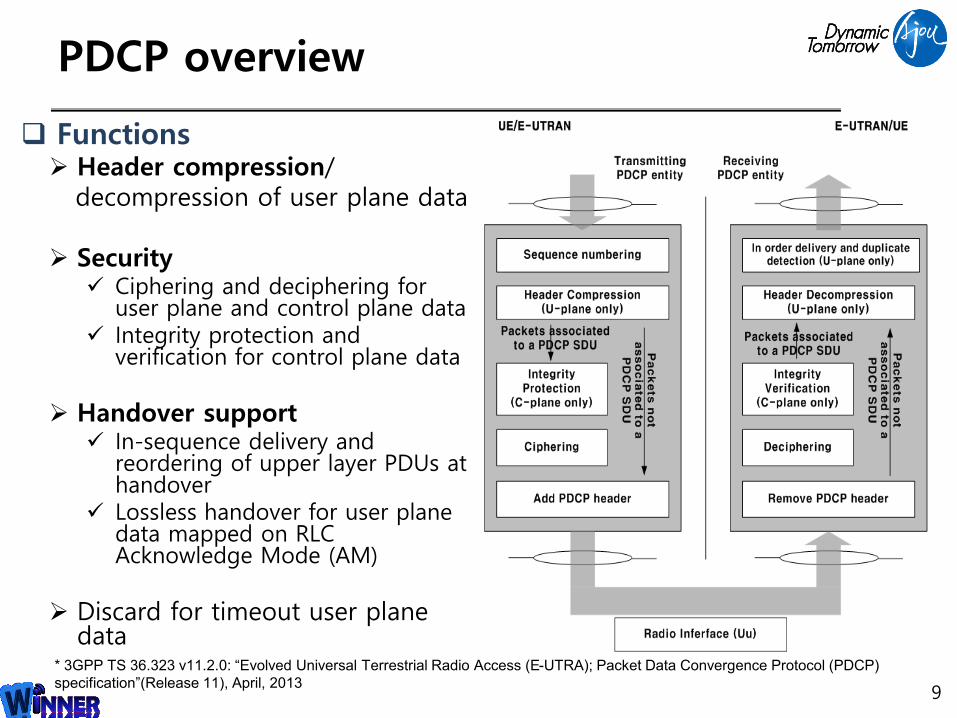
PDCP overview
9
Functions Header compression/
decompression of user plane data
Security Ciphering and deciphering for
user plane and control plane data Integrity protection and
verification for control plane data
Handover support In-sequence delivery and
reordering of upper layer PDUs at handover
Lossless handover for user plane data mapped on RLC Acknowledge Mode (AM)
Discard for timeout user plane data
* 3GPP TS 36.323 v11.2.0: “Evolved Universal Terrestrial Radio Access (E-UTRA); Packet Data Convergence Protocol (PDCP)
specification”(Release 11), April, 2013
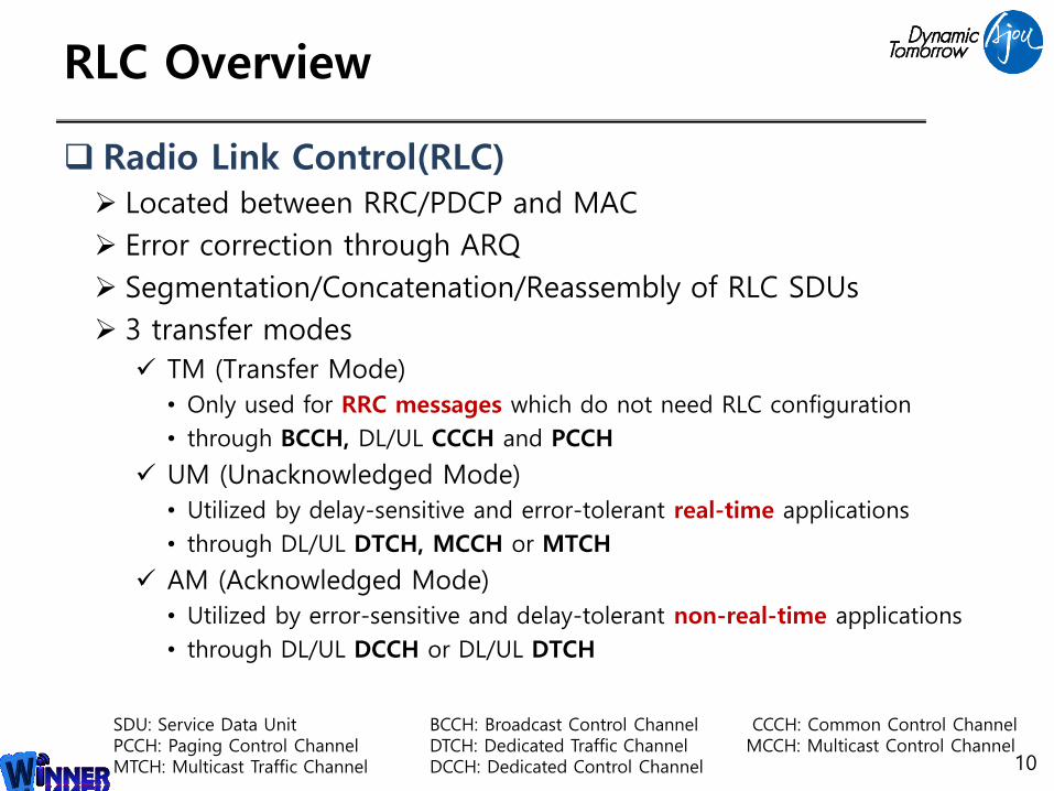
RLC Overview
Radio Link Control(RLC) Located between RRC/PDCP and MAC
Error correction through ARQ
Segmentation/Concatenation/Reassembly of RLC SDUs
3 transfer modes
TM (Transfer Mode)
• Only used for RRC messages which do not need RLC configuration
• through BCCH, DL/UL CCCH and PCCH
UM (Unacknowledged Mode)
• Utilized by delay-sensitive and error-tolerant real-time applications
• through DL/UL DTCH, MCCH or MTCH
AM (Acknowledged Mode)
• Utilized by error-sensitive and delay-tolerant non-real-time applications
• through DL/UL DCCH or DL/UL DTCH
10
SDU: Service Data Unit BCCH: Broadcast Control Channel CCCH: Common Control ChannelPCCH: Paging Control Channel DTCH: Dedicated Traffic Channel MCCH: Multicast Control ChannelMTCH: Multicast Traffic Channel DCCH: Dedicated Control Channel
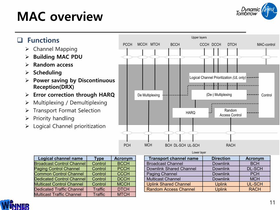
MAC overview
11
Random
Access Control
PCCH BCCH CCCH DCCH DTCH MAC-control
Upper layers
PCH BCH DL-SCH UL-SCH RACH
Lower layer
(De-) Multiplexing
Logical Channel Prioritization (UL only)
HARQ
Control
MCCH MTCH
MCH
De Multiplexing
Transport channel name Direction Acronym
Broadcast Channel Downlink BCH
Downlink Shared Channel Downlink DL-SCH
Paging Channel Downlink PCH
Multicast Channel Downlink MCH
Uplink Shared Channel Uplink UL-SCH
Random Access Channel Uplink RACH
Logical channel name Type Acronym
Broadcast Control Channel Control BCCH
Paging Control Channel Control PCCH
Common Control Channel Control CCCH
Dedicated Control Channel Control DCCH
Multicast Control Channel Control MCCH
Dedicated Traffic Channel Traffic DTCH
Multicast Traffic Channel Traffic MTCH
Functions Channel Mapping
Building MAC PDU
Random access
Scheduling
Power saving by Discontinuous Reception(DRX)
Error correction through HARQ
Multiplexing / Demultiplexing
Transport Format Selection
Priority handling
Logical Channel prioritization
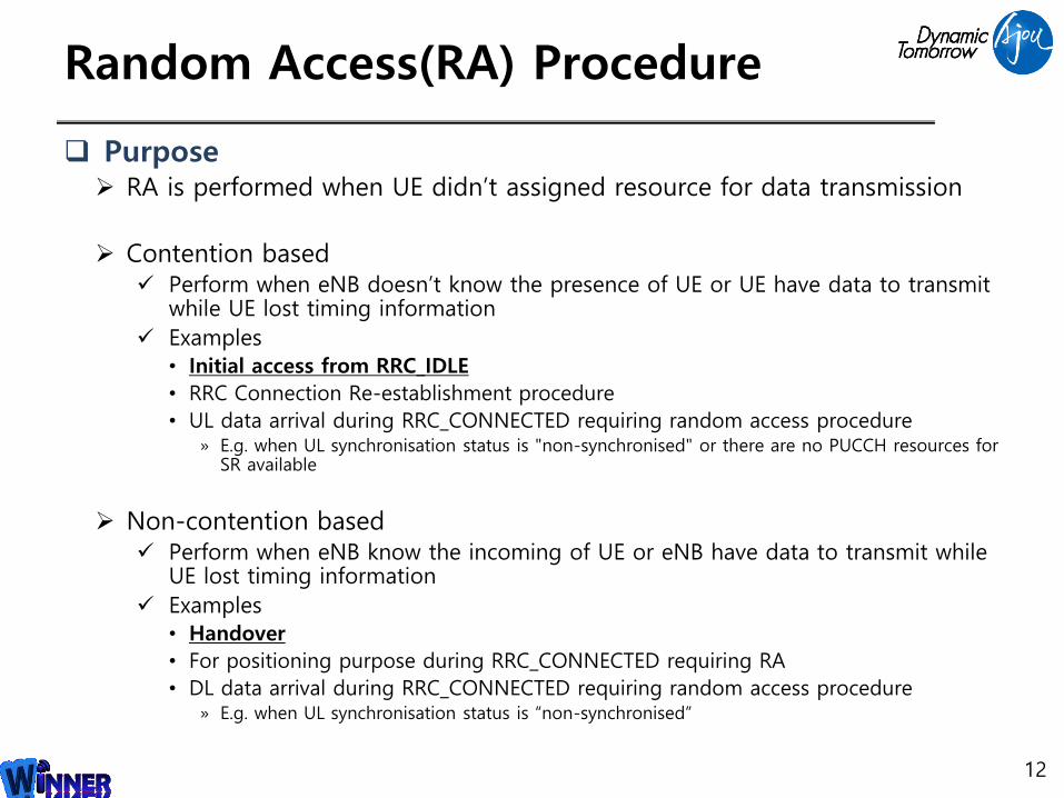
Random Access(RA) Procedure
Purpose RA is performed when UE didn’t assigned resource for data transmission
Contention based Perform when eNB doesn’t know the presence of UE or UE have data to transmit
while UE lost timing information
Examples• Initial access from RRC_IDLE
• RRC Connection Re-establishment procedure
• UL data arrival during RRC_CONNECTED requiring random access procedure» E.g. when UL synchronisation status is "non-synchronised" or there are no PUCCH resources for
SR available
Non-contention based Perform when eNB know the incoming of UE or eNB have data to transmit while
UE lost timing information
Examples• Handover
• For positioning purpose during RRC_CONNECTED requiring RA
• DL data arrival during RRC_CONNECTED requiring random access procedure» E.g. when UL synchronisation status is “non-synchronised”
12
Random Access Procedure- Contention based(1)
13
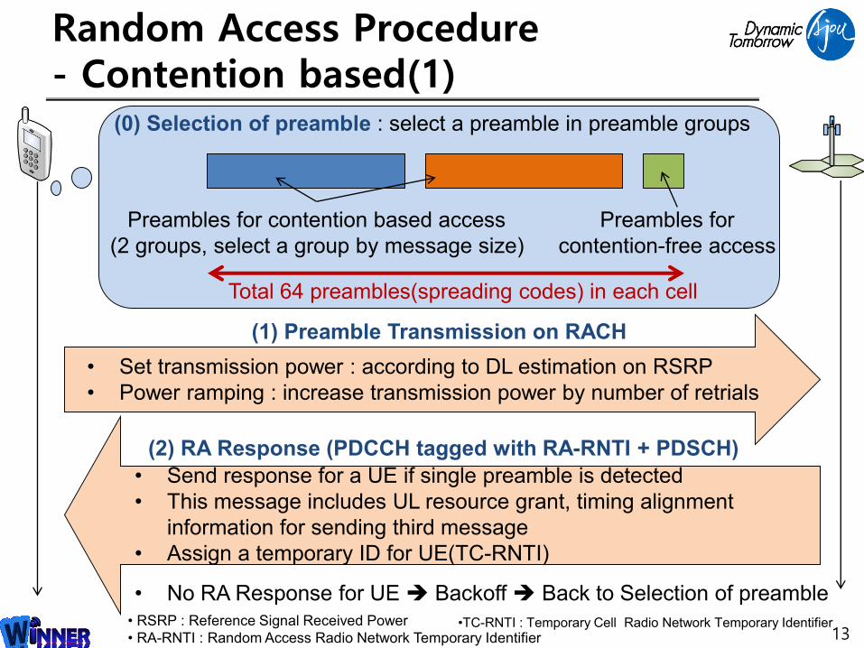
(0) Selection of preamble : select a preamble in preamble groups
Preambles for contention based access
(2 groups, select a group by message size)
Total 64 preambles(spreading codes) in each cell
Preambles for
contention-free access
(1) Preamble Transmission on RACH
• Set transmission power : according to DL estimation on RSRP
• Power ramping : increase transmission power by number of retrials
(2) RA Response (PDCCH tagged with RA-RNTI + PDSCH)
• Send response for a UE if single preamble is detected
• This message includes UL resource grant, timing alignment
information for sending third message
• Assign a temporary ID for UE(TC-RNTI)
• RSRP : Reference Signal Received Power
• RA-RNTI : Random Access Radio Network Temporary Identifier•TC-RNTI : Temporary Cell Radio Network Temporary Identifier
• No RA Response for UE Backoff Back to Selection of preamble
Random Access Procedure- Contention based(2)
14
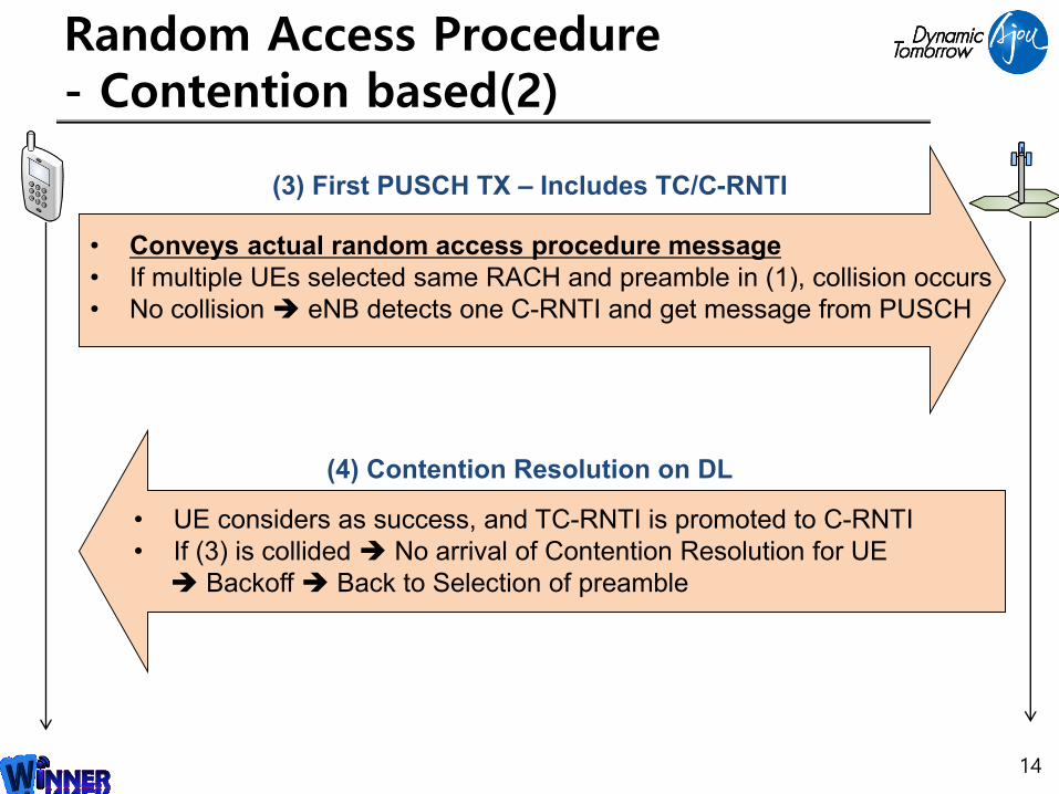
(3) First PUSCH TX – Includes TC/C-RNTI
• Conveys actual random access procedure message
• If multiple UEs selected same RACH and preamble in (1), collision occurs
• No collision eNB detects one C-RNTI and get message from PUSCH
• UE considers as success, and TC-RNTI is promoted to C-RNTI
• If (3) is collided No arrival of Contention Resolution for UE
Backoff Back to Selection of preamble
(4) Contention Resolution on DL
Random Access Procedure- Non-Contention based
15
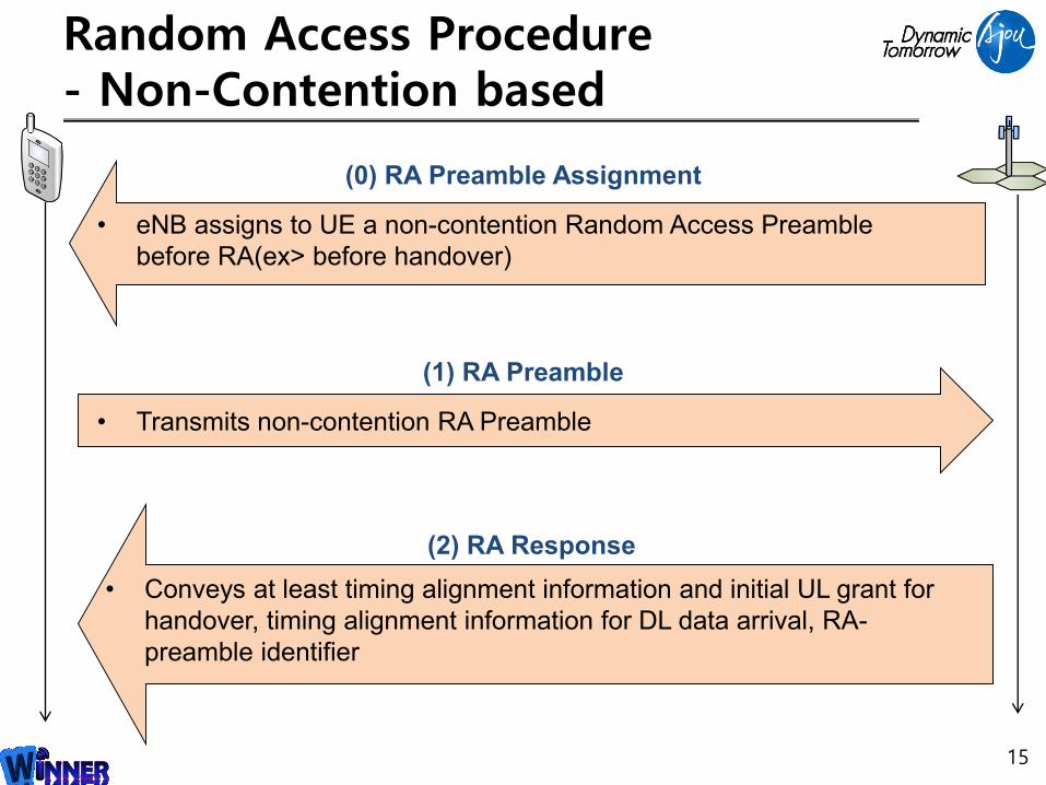
(0) RA Preamble Assignment
(1) RA Preamble
(2) RA Response
• eNB assigns to UE a non-contention Random Access Preamble
before RA(ex> before handover)
• Transmits non-contention RA Preamble
• Conveys at least timing alignment information and initial UL grant for
handover, timing alignment information for DL data arrival, RA-
preamble identifier
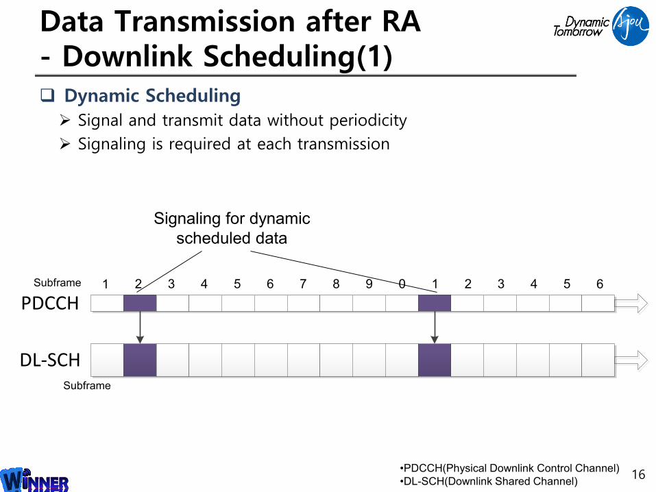
Data Transmission after RA- Downlink Scheduling(1) Dynamic Scheduling
Signal and transmit data without periodicity
Signaling is required at each transmission
16
Signaling for dynamic
scheduled data
PDCCH
DL-SCH
•PDCCH(Physical Downlink Control Channel)
•DL-SCH(Downlink Shared Channel)
Subframe
Subframe 1 2 3 4 5 6 7 8 9 0 1 2 3 4 5 6

Data Transmission after RA- Downlink Scheduling(2) Semi-persistent scheduling
Schedule periodical transmission
Only the one signaling at first transmission is required
Reduce signaling overhead
Scheduling periodicity is configured by RRC
17
PDCCH
DL-SCH
Signaling for semi-persistent data
(example : period = 4)
No additional signalling for semi-
persistent scheduled data
Subframe 1 2 3 4 5 6 7 8 9 0 1 2 3 4 5 6

Data Transmission after RA- Uplink Scheduling Procedure
eNodeB notifies the TX slot which can be used by UE for uplink transmission
UE sends data through UL-SCH and activates HARQ process
HARQ mechanism : Stop-and-Wait
eNodeB signals transmission result by HARQ ACK/NACK to UE
For NACK, eNodeB schedule for retransmission through PDCCH
18
Tx in 5
Txin 7
Tx in 7
ULData
PDCCH
UL-SCH
ACK NACKPHICH
1 2 3 4 5 6 7 8 9 0 1 2 3 4 5 6
ULData
7
ULData
N=4 N=4UE Response eNB Response
Subframe
• Example for N=4 : UE/eNB response after 4 subframe
•PDCCH(Physical Downlink Control Channel)
•UL-SCH(Uplink Shared Channel)
•PHICH(Physical HARQ Indicator Channel)
Wireless Packet Scheduling Algorithm
Features of Scheduling Algorithms for Wireless Network Each user experience different transmission speed
Channel environment differ by randomly through time
Bursty error occurs
User’s channel capacity changes by fading
Require to estimate channel environment
19
• Additional Slides
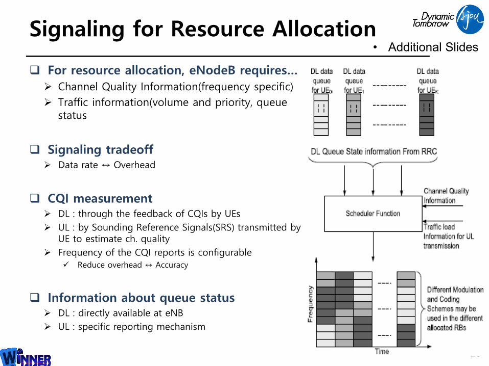
Signaling for Resource Allocation
For resource allocation, eNodeB requires…
Channel Quality Information(frequency specific)
Traffic information(volume and priority, queue status
Signaling tradeoff Data rate ↔ Overhead
CQI measurement DL : through the feedback of CQIs by UEs
UL : by Sounding Reference Signals(SRS) transmitted by UE to estimate ch. quality
Frequency of the CQI reports is configurable
Reduce overhead ↔ Accuracy
Information about queue status DL : directly available at eNB
UL : specific reporting mechanism
20
• Additional Slides
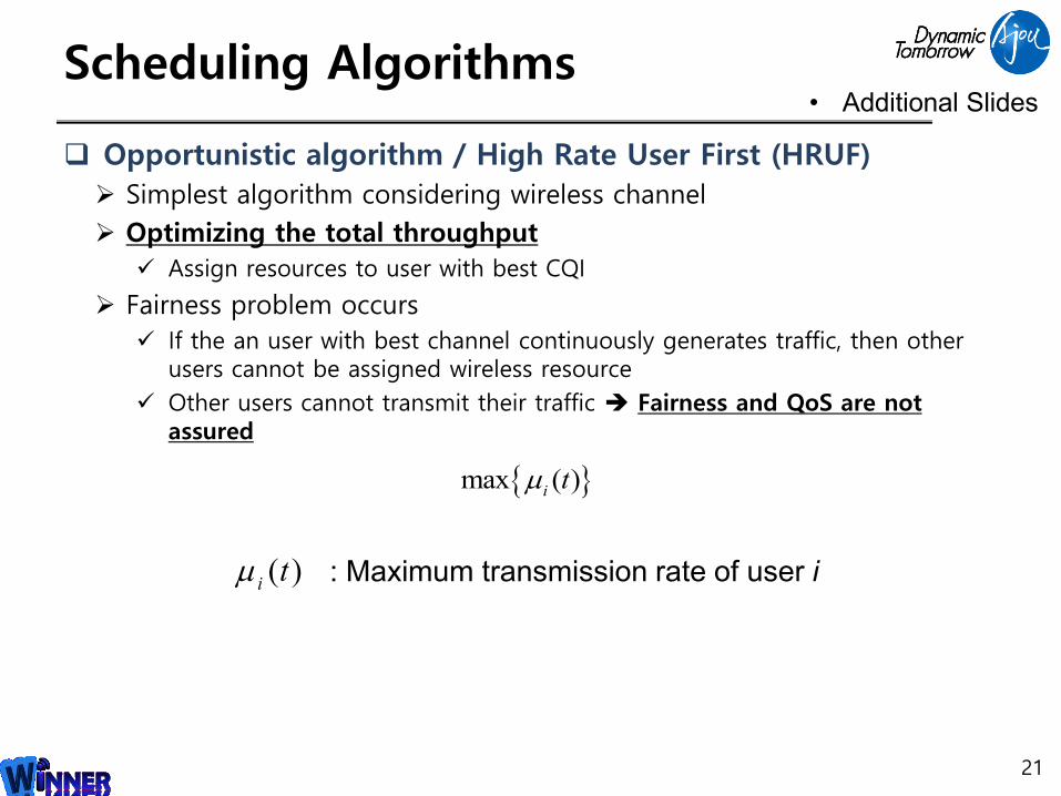
Scheduling Algorithms
Opportunistic algorithm / High Rate User First (HRUF)
Simplest algorithm considering wireless channel
Optimizing the total throughput
Assign resources to user with best CQI
Fairness problem occurs
If the an user with best channel continuously generates traffic, then other users cannot be assigned wireless resource
Other users cannot transmit their traffic Fairness and QoS are not assured
21
max ( )it
( )it : Maximum transmission rate of user i
• Additional Slides
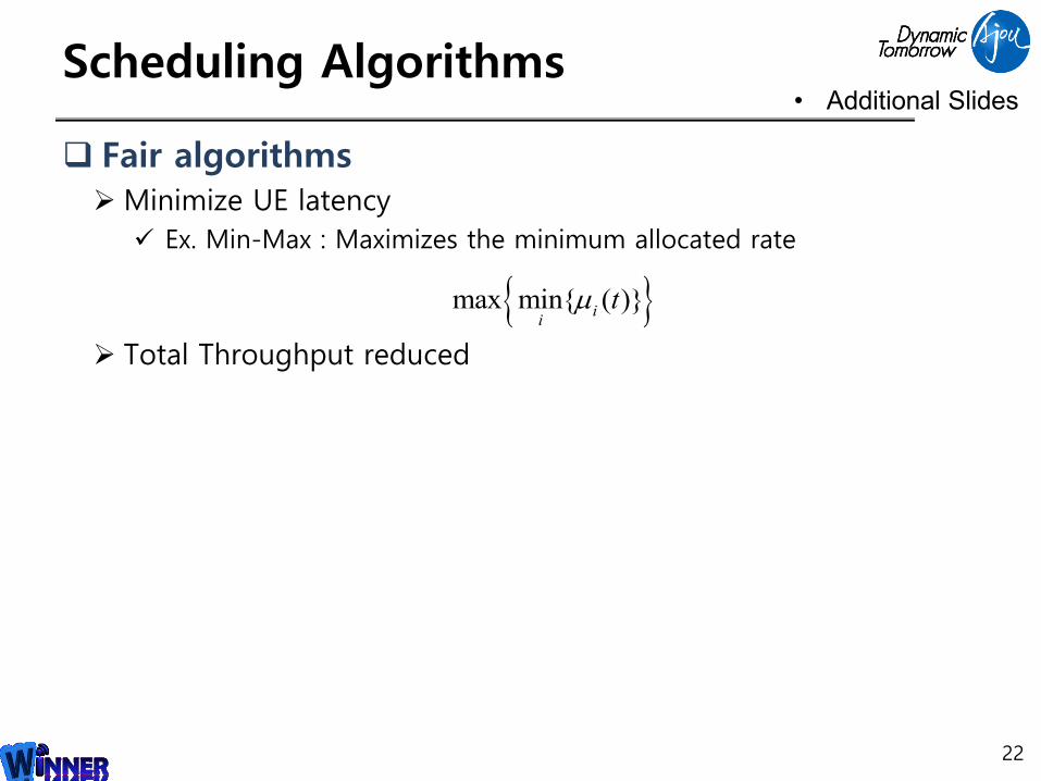
Scheduling Algorithms
Fair algorithmsMinimize UE latency
Ex. Min-Max : Maximizes the minimum allocated rate
Total Throughput reduced
22
max min{ ( )}i
it
• Additional Slides
Scheduling Algorithms
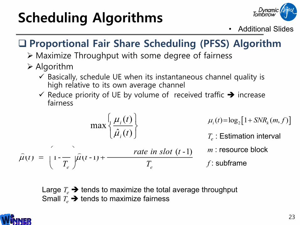
Proportional Fair Share Scheduling (PFSS) AlgorithmMaximize Throughput with some degree of fairness
Algorithm Basically, schedule UE when its instantaneous channel quality is
high relative to its own average channel
Reduce priority of UE by volume of received traffic increase fairness
23
( )max
ˆ ( )
i
i
t
t
1 ( -1)( ) 1- ( -1)
e e
served rate in slot tt t
T T
Te : Estimation interval
m : resource block
f : subframe
2( ) log 1 ( , )i kt SNR m f
Large Te tends to maximize the total average throughput
Small Te tends to maximize fairness
• Additional Slides

Full duplex Technology
24

Full duplex technology
Self interference cancellation(SIC) Key technology to implement full duplex communication
At least -110dB cancellation is required
Self interference
Interference from transmitting signal to receiving signal
25
Tx Rx
Transmitting Signal Receiving Signal
SelfInterference
Full duplex technology
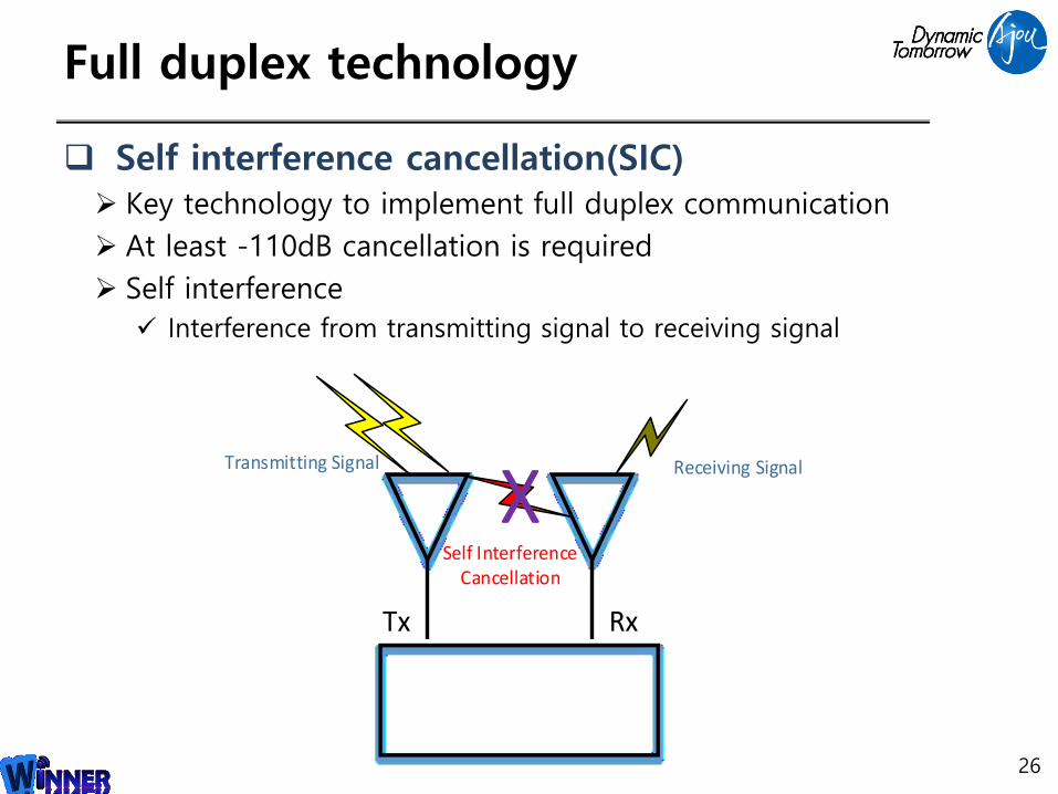
Self interference cancellation(SIC) Key technology to implement full duplex communication
At least -110dB cancellation is required
Self interference
Interference from transmitting signal to receiving signal
26
Tx Rx
Transmitting Signal Receiving Signal
XSelf Interference
Cancellation
Full duplex technology
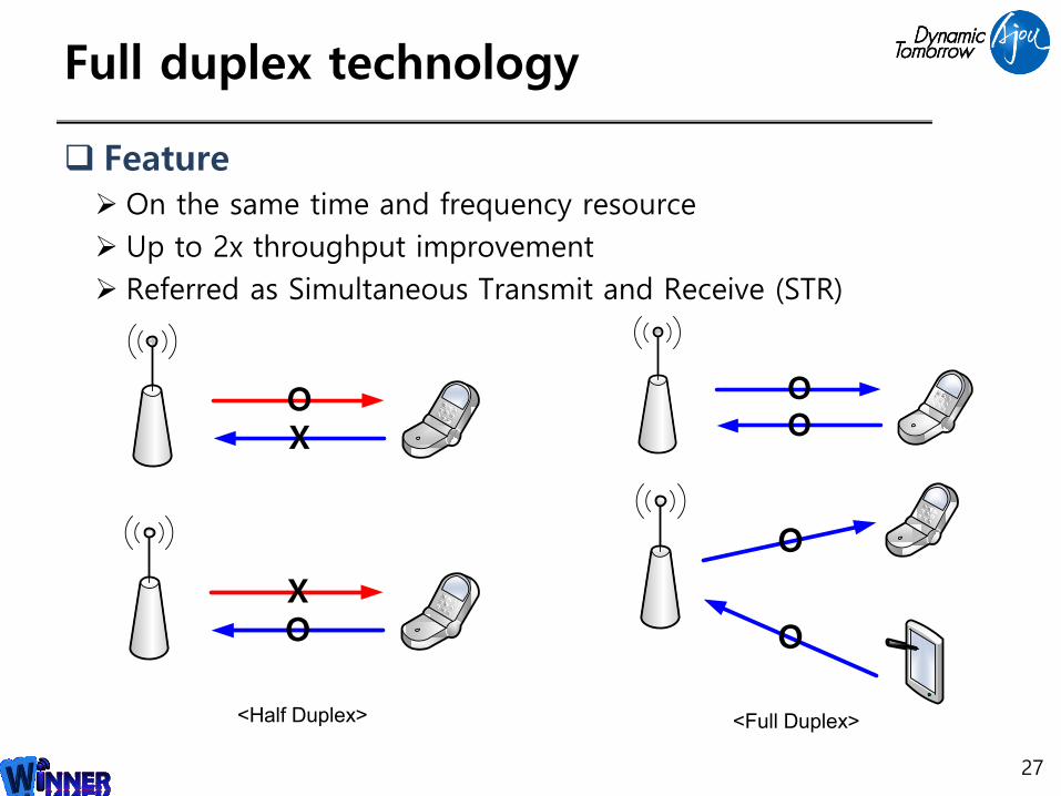
Feature On the same time and frequency resource
Up to 2x throughput improvement
Referred as Simultaneous Transmit and Receive (STR)
27
OO
O
O
<Full Duplex>
OX
OX
<Half Duplex>
Technical issues of full duplex MAC protocols
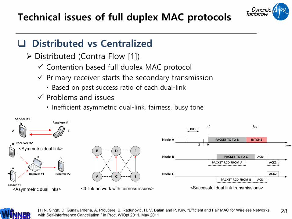
Distributed vs Centralized Distributed (Contra Flow [1])
Contention based full duplex MAC protocol
Primary receiver starts the secondary transmission
• Based on past success ratio of each dual-link
Problems and issues
• Inefficient asymmetric dual-link, fairness, busy tone
28[1] N. Singh, D. Gunawardena, A. Proutiere, B. Radunović, H. V. Balan and P. Key, “Efficient and Fair MAC for Wireless Networks
with Self-interference Cancellation,” in Proc. WiOpt 2011, May 2011
Sender #1
A
Receiver #2
B
Receiver #1
A
B C
D
Sender #1
Receiver #1 Receiver #2
<Symmetric dual link>
<Asymmetric dual links>
PACKET TX TO C
PACKET TX TO B
DIFS
Node A
Node B
2 1 0
B/TONE
t=0 tend
time
Node C
ACK1
PACKET RCD FROM A ACK2
ACK2
PACKET RCD FROM B ACK1
<Successful dual link transmissions>
B
A
D
C
F
E
<3-link network with fairness issues>
Technical issues of full duplex MAC protocols
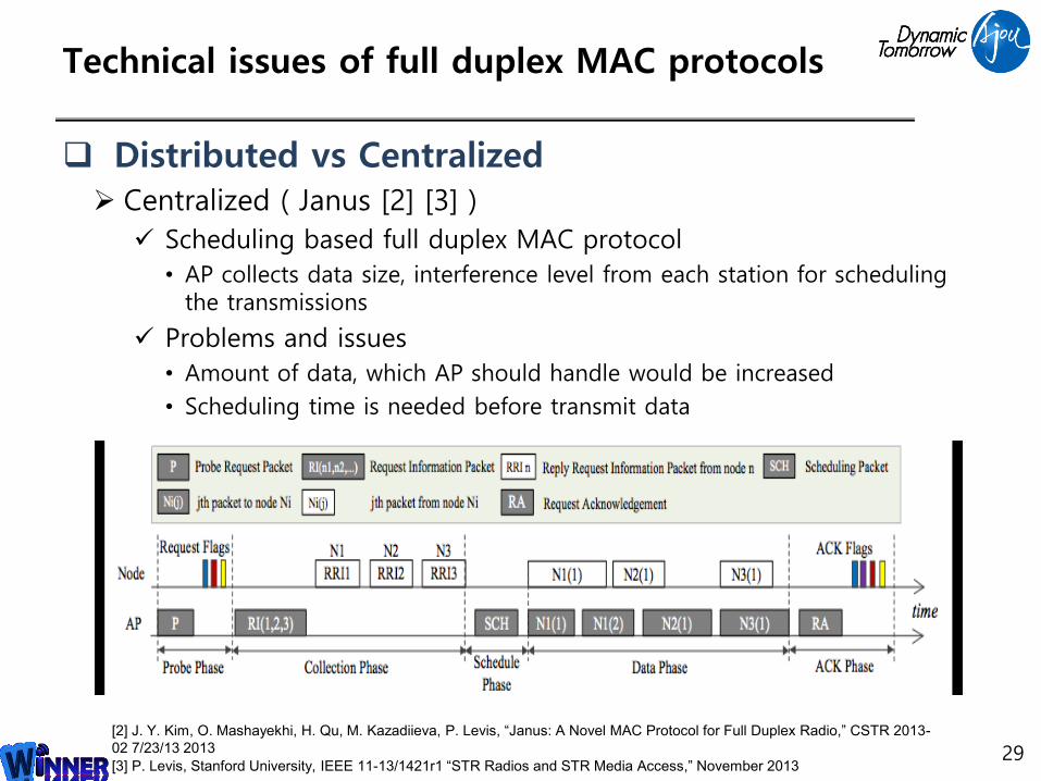
Distributed vs Centralized Centralized ( Janus [2] [3] )
Scheduling based full duplex MAC protocol
• AP collects data size, interference level from each station for scheduling the transmissions
Problems and issues
• Amount of data, which AP should handle would be increased
• Scheduling time is needed before transmit data
29[2] J. Y. Kim, O. Mashayekhi, H. Qu, M. Kazadiieva, P. Levis, “Janus: A Novel MAC Protocol for Full Duplex Radio,” CSTR 2013-
02 7/23/13 2013
[3] P. Levis, Stanford University, IEEE 11-13/1421r1 “STR Radios and STR Media Access,” November 2013
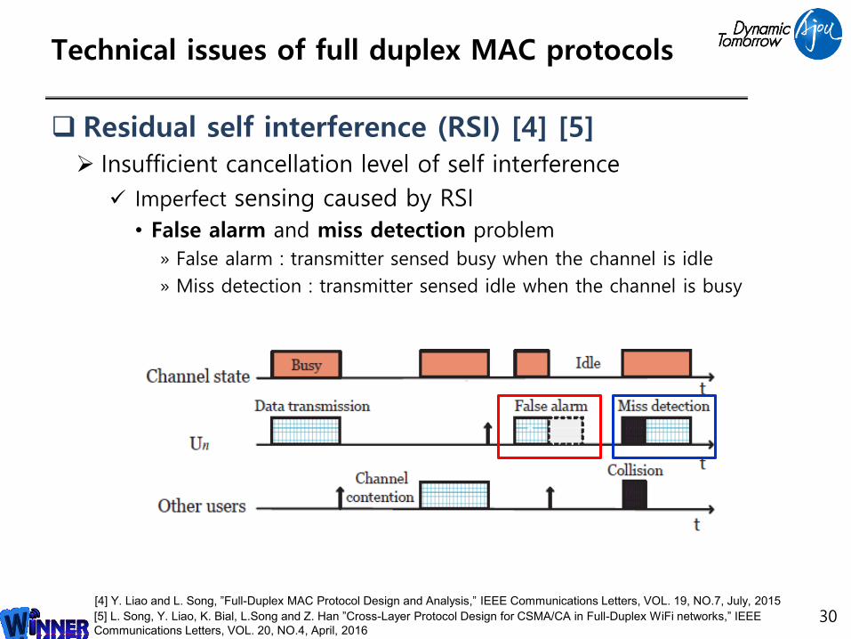
Technical issues of full duplex MAC protocols
Residual self interference (RSI) [4] [5] Insufficient cancellation level of self interference
Imperfect sensing caused by RSI
• False alarm and miss detection problem
» False alarm : transmitter sensed busy when the channel is idle
» Miss detection : transmitter sensed idle when the channel is busy
30[4] Y. Liao and L. Song, ”Full-Duplex MAC Protocol Design and Analysis,” IEEE Communications Letters, VOL. 19, NO.7, July, 2015
[5] L. Song, Y. Liao, K. Bial, L.Song and Z. Han ”Cross-Layer Protocol Design for CSMA/CA in Full-Duplex WiFi networks,” IEEE
Communications Letters, VOL. 20, NO.4, April, 2016
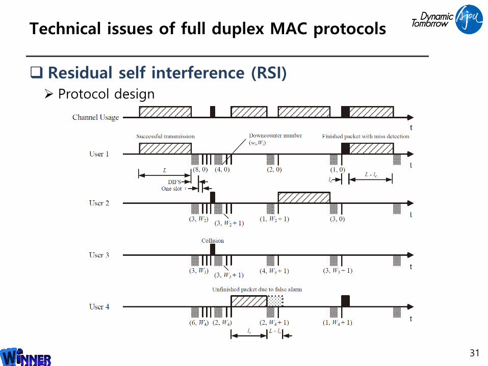
Technical issues of full duplex MAC protocols
Residual self interference (RSI) Protocol design
31
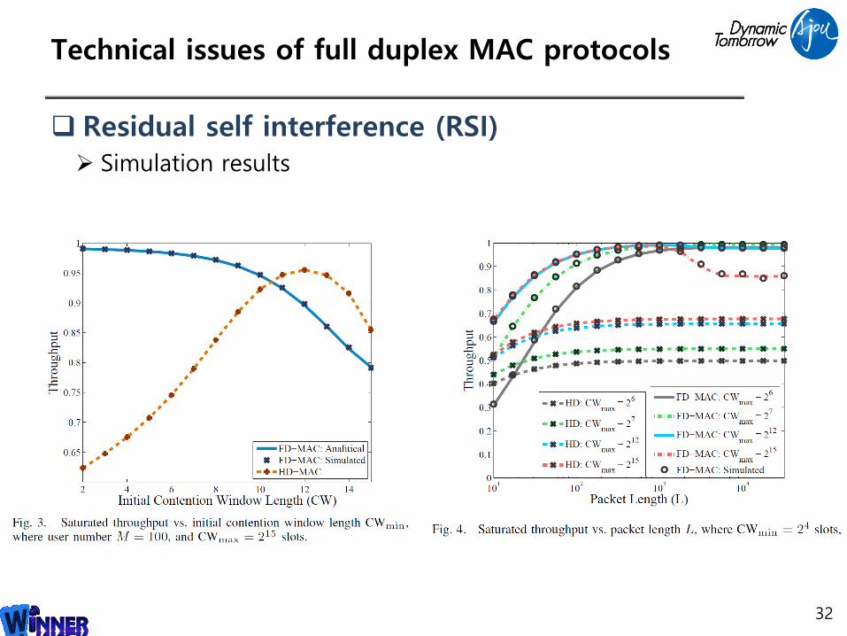
Technical issues of full duplex MAC protocols
32
Residual self interference (RSI) Simulation results

Technical issues of full duplex MAC protocols
Backward comparability Coexistence of half duplex and full duplex devices
Must be considered for transition period
Asymmetrical-Duplex [6] Network with full duplex AP and half duplex stations
Support efficient coexistence between half duplex clients and the full duplex AP
Considers capture effects
AP uses SIR map when choosing downlink transmission
Tradeoff between fairness and throughput
• Nearest station is always the best choice to improve throughput
33[6] A. Tang and X. Wang, ”A-Duplex: Medium Access Control for Efficient Coexistence Between Full-Duplex and Half-Duplex
Communications,” IEEE Transactions on Wireless Communications, Vol. 14, NO. 10, October, 2015
Technical issues of full duplex MAC protocols
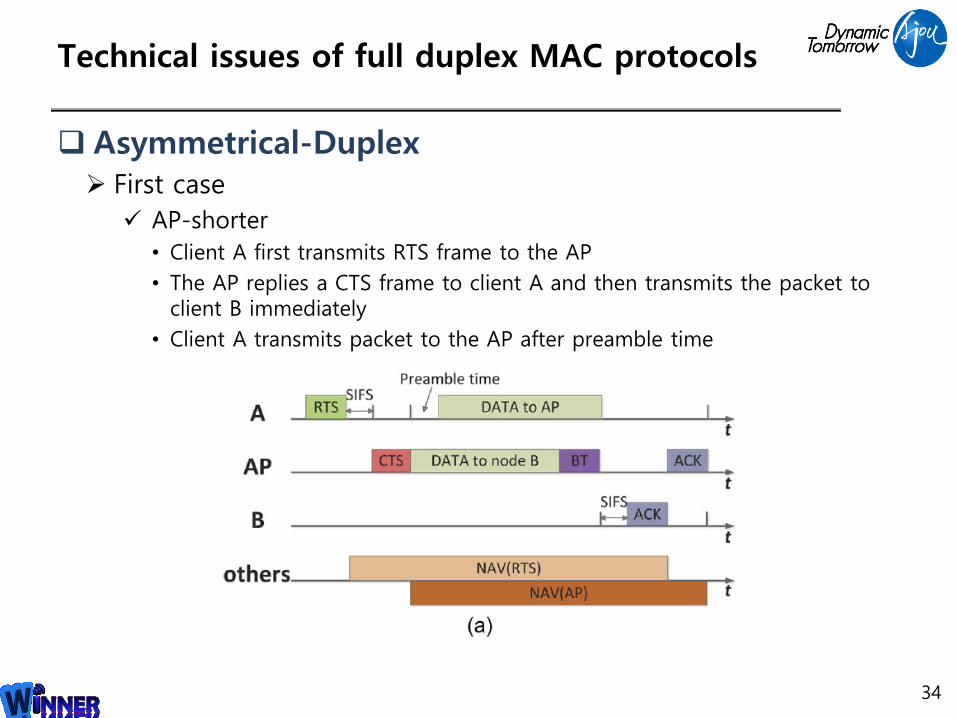
Asymmetrical-Duplex First case
AP-shorter
• Client A first transmits RTS frame to the AP
• The AP replies a CTS frame to client A and then transmits the packet to client B immediately
• Client A transmits packet to the AP after preamble time
34

Technical issues of full duplex MAC protocols
Asymmetrical-Duplex Second case
AP-longer
• Client A first transmits RTS frame to the AP
• The AP replies a CTS frame to client A and then transmits the packet to client B immediately
• Client A delays its transmission for enough time such that two transmissions finish simultaneously
35
Technical issues of full duplex MAC protocols
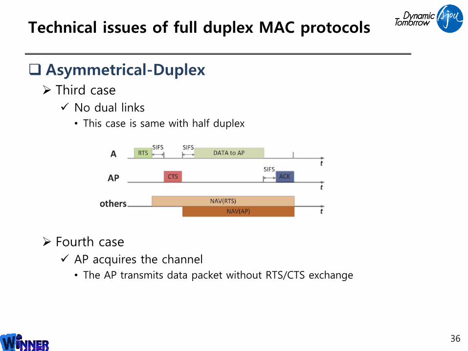
Asymmetrical-Duplex Third case
No dual links
• This case is same with half duplex
Fourth case
AP acquires the channel
• The AP transmits data packet without RTS/CTS exchange
36
Technical issues of full duplex MAC protocols
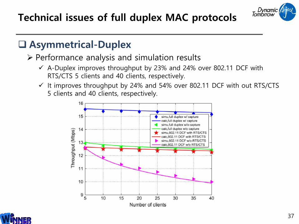
Asymmetrical-Duplex Performance analysis and simulation results
A-Duplex improves throughput by 23% and 24% over 802.11 DCF with RTS/CTS 5 clients and 40 clients, respectively.
It improves throughput by 24% and 54% over 802.11 DCF with out RTS/CTS 5 clients and 40 clients, respectively.
37

LTE 적용 예시
38

Uplink / Downlink 공유
FDD 방식 FDD 방식의 경우 Uplink와 downlink의 주파수 영역이 다름
Self interference cancellation을 통해 간섭 제거
Uplink와 downlink 같은 주파수 영역 사용 가능
39
Uplink (10MHz)
Downlink (10MHz)
Uplink (20MHz)
Downlink (20MHz)
Uplink DownlinkFrequency ~ ~10Mhz 10MHz
Uplink / Downlink Uplink / DownlinkFrequency ~ ~10Mhz 10MHz
Uplink / Downlink 공유
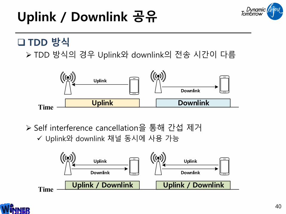
TDD 방식 TDD 방식의 경우 Uplink와 downlink의 전송 시간이 다름
Self interference cancellation을 통해 간섭 제거
Uplink와 downlink 채널 동시에 사용 가능
40
Uplink DownlinkTime
Uplink
Downlink
Uplink / Downlink Uplink / DownlinkTime
Uplink
Downlink
Uplink
Downlink
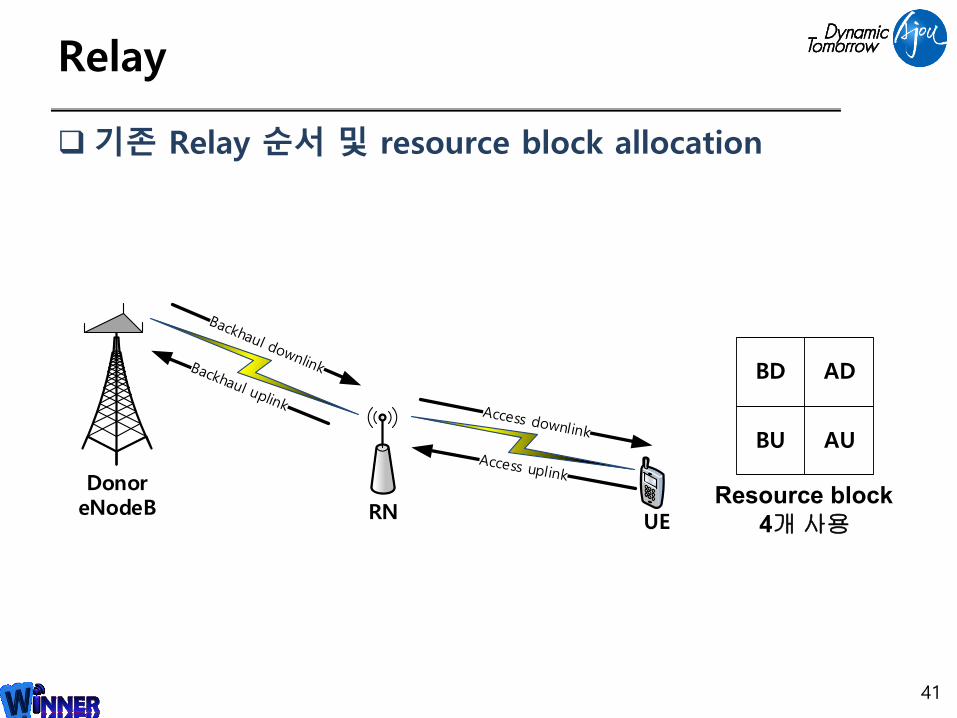
Relay
기존 Relay 순서 및 resource block allocation
41
DonoreNodeB RN UE
BD AD
AUBU
Resource block
4개사용
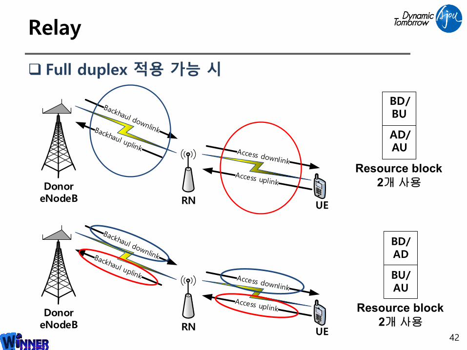
Relay
Full duplex 적용 가능 시
42
DonoreNodeB RN UE
Resource block
2개사용
BD/AD
BU/AU
DonoreNodeB RN UE
Resource block
2개사용
BD/BU
AD/AU
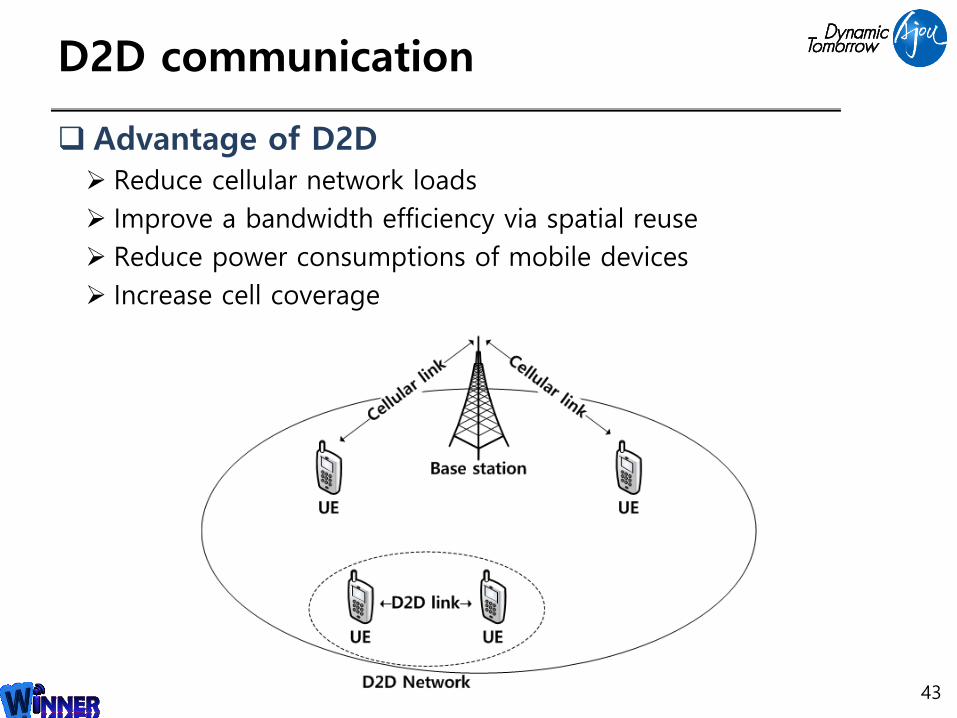
D2D communication
Advantage of D2D Reduce cellular network loads
Improve a bandwidth efficiency via spatial reuse
Reduce power consumptions of mobile devices
Increase cell coverage
43

Full duplex 구현 시 고려사항
44
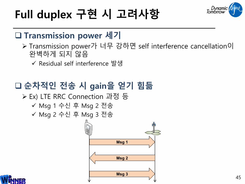
Full duplex 구현 시 고려사항
Transmission power 세기 Transmission power가 너무 강하면 self interference cancellation이
완벽하게 되지 않음
Residual self interference 발생
순차적인 전송 시 gain을 얻기 힘듦 Ex) LTE RRC Connection 과정 등
Msg 1 수신 후 Msg 2 전송
Msg 2 수신 후 Msg 3 전송
45
Msg 1
Msg 2
Msg 3
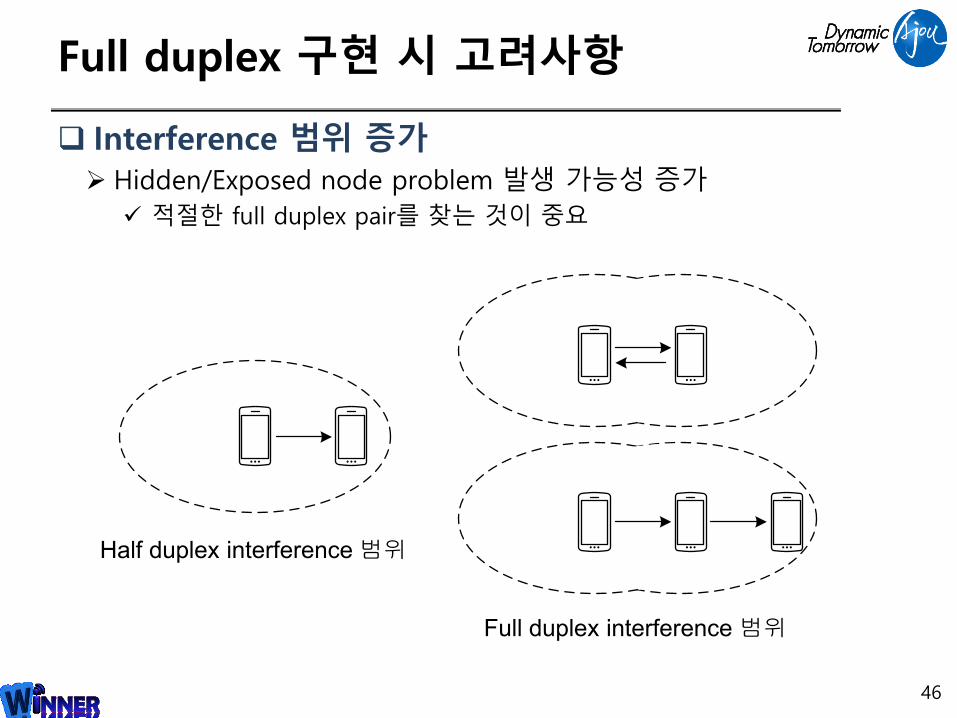
Full duplex 구현 시 고려사항
Interference 범위 증가 Hidden/Exposed node problem 발생 가능성 증가
적절한 full duplex pair를 찾는 것이 중요
46
Half duplex interference 범위
Full duplex interference 범위
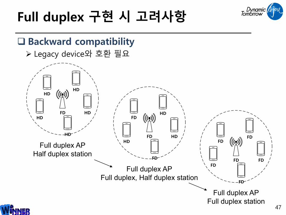
Full duplex 구현 시 고려사항
Backward compatibility Legacy device와 호환 필요
47
FD
HDHD
HD
HDHD
Full duplex AP
Half duplex station
FD
HDFD
FD
HDHD
Full duplex AP
Full duplex, Half duplex station
FD
FDFD
FD
FDFD
Full duplex AP
Full duplex station

Thank you !
Q & A
48
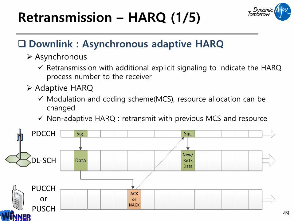
Retransmission – HARQ (1/5)
Downlink : Asynchronous adaptive HARQ Asynchronous
Retransmission with additional explicit signaling to indicate the HARQ process number to the receiver
Adaptive HARQ
Modulation and coding scheme(MCS), resource allocation can be changed
Non-adaptive HARQ : retransmit with previous MCS and resource
49
Sig.
Data
PDCCH
DL-SCH
ACK or
NACK
PUCCHor
PUSCH
Sig.
New/ReTxData

Retransmission – HARQ (2/5)
Uplink : Synchronous Non-adaptive/adaptive HARQ Uplink : Synchronous HARQ
Synchronous
• Retransmission occur at predefined times relative to the initial transmission to reduce control signaling
50
Grant
Data
PDCCH
UL-SCH
Grant
New/ReTxData
PHICHACK /NACK
HARQ
feedback seen
by the UE
PDCCH
seen by
the UE
UE behaviour
ACK
or NACK
New
Transmission
New transmission according
to PDCCH
ACK
or NACK
Retrans-
mission
Retransmission according to
PDCCH(adaptive retransmission)
ACK None
No (re)transmission
PDCCH is required to resume
Retransmissions
NACK None Non-adaptive retransmission

Power Saving/Fast Wake-up –Discontinuous Reception(DRX)
51
CELL_DCH
CELL_FACH
CELL_PCHURA_PCH
IDLE_MODE
TX delay
Power Consumption
High Transition Delay(2~3sec) Lex> click after web page view
to reduce battery consumption
state changesex> during web page reading
Power saving in UMTS Through the state change from CELL_DCH to IDLE_MODE
Fast recovering to CELL_DCH takes undesired delay
•DCH (Dedicated Channel)
•FACH (Forward access channel)
•PCH (Cell Paging channel)
•URA_PCH (URA Paging channel).
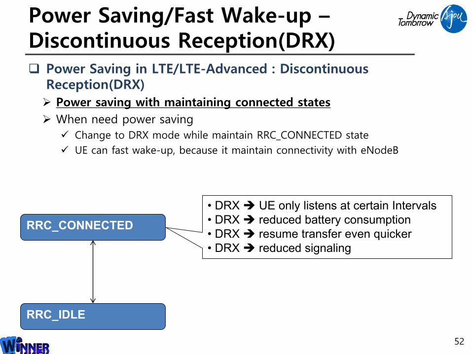
Power Saving/Fast Wake-up –Discontinuous Reception(DRX)
52
RRC_CONNECTED
RRC_IDLE
• DRX UE only listens at certain Intervals
• DRX reduced battery consumption
• DRX resume transfer even quicker
• DRX reduced signaling
Power Saving in LTE/LTE-Advanced : Discontinuous Reception(DRX)
Power saving with maintaining connected states
When need power saving
Change to DRX mode while maintain RRC_CONNECTED state
UE can fast wake-up, because it maintain connectivity with eNodeB

Power Saving/Fast Wake-up –Discontinuous Reception (DRX) UE does not monitor the downlink channels during
such DRX period HARQ Round Trip Time (RTT)
Short cycle, Long cycle Wake-up and check downlink during “on duration” only
By two timer, control wake-up interval(=short DRX cycle and long DRX cycle)
53
①
③
Activate
Inactivity timer
Activate
Short DRX Cycle Timer
④
② ⑤
⑥ enter short DRX mode enter long DRX mode