FRICTION STIR WELDING OF ELEMENTS MADE OF CAST ... - … · FSW (Friction Stir Welding) is the...
8
A R C H I V E S O F M E T A L L U R G Y A N D M A T E R I A L S Volume 59 2014 Issue 1 DOI: 10.2478/amm-2014-0064 B. RAMS * , A. PIETRAS * , K. MROCZKA ** FRICTION STIR WELDING OF ELEMENTS MADE OF CAST ALUMINIUM ALLOYS ZGRZEWANIE METODĄ FSW ELEMENTÓW WYKONANYCH Z ODLEWNICZYCH STOPÓW ALUMINIUM The article presents application of FSW method for joining elements made of cast aluminium alloys which are hardly weldable with other known welding techniques. Research’s results of plasticizing process of aluminium and moulding of seam weld during different FSW process’ conditions were also presented. Influence of welding parameters, shape and dimensions of tool on weld structure, welding stability and quality was examined. Application of FSW method was exemplified on welding of hemispheres for valves made of cast aluminium alloy EN AC-43200. Keywords: Friction Welding, FSW, butt welding, cast aluminium alloy W artykule przedstawiono zastosowanie metody FSW do lączenia elementów z trudno spajanego znanymi technikami spawalniczymi aluminium odlewniczego. Przedstawiono również wyniki badania procesu uplastyczniania aluminium oraz for- mowania się zgrzeiny liniowej w różnych warunkach prowadzenia procesu zgrzewania FSW. Badano wplyw parametrów procesu zgrzewania oraz ksztalt i wymiary narzędzia na strukturę zgrzein oraz na stabilność i jakość zgrzewania. Zastosowanie metody zgrzewania FSW przedstawiono na przykladzie lączenia czasz kul zaworów wykonanych z odlewniczego stopu aluminium EN AC-43200. 1. Introduction FSW (Friction Stir Welding) is the method that makes it possible to successfully join aluminium and its alloys, in- cluding casting alloys which are difficult to weld using known welding techniques. This method is increasingly used in the world mainly in the shipbuilding, rail, automotive and building industries. In FSW process the stirring and rotating tool penetrating material along the line of welding is applied for the friction heating and softening material. After the tool is put into rota- tion and frictional heating and softening the material around the probe, the tool is traversed along the joint line. The heat- ed and plasticised materials of the components being welded are extruded around the tool probe backwards, where before cooling down they are stirred and upset by the shoulder. In the centre of the weld the zone called “nugget” is formed in the result of the stirring of the softened metals of both parts being welded behind the tool [1,2]. The shape and dimensions of the weld depend on the shape and size of the stirring tool and applied welding para- meters. Basic parameters of FSW process comprise: tool rota- tion speed, V n [rpm]; welding speed, V zg [mm/min]; tilt angle, α [ ◦ ]; tool type and size of the tool: probe diameter – d [mm], shoulder diameter – D [mm], probe length – l [mm]. During FSW process material of the workpiece is subject- ed to mechanical stirring and intensive plastic deformation at higher temperature, which spreads out also outside the stirring zone (thermo mechanical affected zone). Additionally, the sig- nificant temperature gradient occurs across the weld outside the thermo mechanical affected zone (heat affected zone). As the result of those factors more complex structure is being formed in the cross-section of the weld, which influences di- rectly its mechanical properties [4-7]. In case of aluminium casting alloys welding, the changes in the microstructure are associated both with processes of deforming, recovery and re- crystallization and also with microstructure component phase changes, e.g. with precipitation or dissolving of intermetallic phases [8]. There is a tendency to produce a weld free from flaws which can occur in conventional arc welding methods. The aim of this research was finding the relation between welding conditions – welding parameters and a tool shape – on a weld structure and the stability and quality of welding. 2. Research station The investigation into FSW process was conducted at Instytut Spawalnictwa on the vertical milling machine FYF32JU2 equipped with special clamps fixing the welded parts. The station for testing of linear welding of plates is * INSTYTUT SPAWALNICTWA W GLIWICACH, ZAKLAD TECHNOLOGII ZGRZEWANIA I INŻYNIERII ŚRODOWISKA, POLAND ** UNIWERSYTET PEDAGOGICZNY W KRAKOWIE, INSTYTUT TECHNIKI, POLAND
Transcript of FRICTION STIR WELDING OF ELEMENTS MADE OF CAST ... - … · FSW (Friction Stir Welding) is the...
A R C H I V E S O F M E T A L L U R G Y A N D M A T E R I A L S
Volume 59 2014 Issue 1
DOI: 10.2478/amm-2014-0064
B. RAMS∗, A. PIETRAS∗, K. MROCZKA∗∗
FRICTION STIR WELDING OF ELEMENTS MADE OF CAST ALUMINIUM ALLOYS
ZGRZEWANIE METODĄ FSW ELEMENTÓW WYKONANYCH Z ODLEWNICZYCH STOPÓW ALUMINIUM
The article presents application of FSW method for joining elements made of cast aluminium alloys which are hardlyweldable with other known welding techniques. Research’s results of plasticizing process of aluminium and moulding of seamweld during different FSW process’ conditions were also presented. Influence of welding parameters, shape and dimensions oftool on weld structure, welding stability and quality was examined. Application of FSW method was exemplified on weldingof hemispheres for valves made of cast aluminium alloy EN AC-43200.
Keywords: Friction Welding, FSW, butt welding, cast aluminium alloy
W artykule przedstawiono zastosowanie metody FSW do łączenia elementów z trudno spajanego znanymi technikamispawalniczymi aluminium odlewniczego. Przedstawiono również wyniki badania procesu uplastyczniania aluminium oraz for-mowania się zgrzeiny liniowej w różnych warunkach prowadzenia procesu zgrzewania FSW. Badano wpływ parametrów procesuzgrzewania oraz kształt i wymiary narzędzia na strukturę zgrzein oraz na stabilność i jakość zgrzewania. Zastosowanie metodyzgrzewania FSW przedstawiono na przykładzie łączenia czasz kul zaworów wykonanych z odlewniczego stopu aluminiumEN AC-43200.
1. Introduction
FSW (Friction Stir Welding) is the method that makesit possible to successfully join aluminium and its alloys, in-cluding casting alloys which are difficult to weld using knownwelding techniques. This method is increasingly used in theworld mainly in the shipbuilding, rail, automotive and buildingindustries.
In FSW process the stirring and rotating tool penetratingmaterial along the line of welding is applied for the frictionheating and softening material. After the tool is put into rota-tion and frictional heating and softening the material aroundthe probe, the tool is traversed along the joint line. The heat-ed and plasticised materials of the components being weldedare extruded around the tool probe backwards, where beforecooling down they are stirred and upset by the shoulder. Inthe centre of the weld the zone called “nugget” is formed inthe result of the stirring of the softened metals of both partsbeing welded behind the tool [1,2].
The shape and dimensions of the weld depend on theshape and size of the stirring tool and applied welding para-meters.
Basic parameters of FSW process comprise: tool rota-tion speed, Vn[rpm]; welding speed, Vzg[mm/min]; tilt angle,α [◦]; tool type and size of the tool: probe diameter – d [mm],shoulder diameter – D [mm], probe length – l [mm].
During FSW process material of the workpiece is subject-ed to mechanical stirring and intensive plastic deformation athigher temperature, which spreads out also outside the stirringzone (thermo mechanical affected zone). Additionally, the sig-nificant temperature gradient occurs across the weld outsidethe thermo mechanical affected zone (heat affected zone). Asthe result of those factors more complex structure is beingformed in the cross-section of the weld, which influences di-rectly its mechanical properties [4-7]. In case of aluminiumcasting alloys welding, the changes in the microstructure areassociated both with processes of deforming, recovery and re-crystallization and also with microstructure component phasechanges, e.g. with precipitation or dissolving of intermetallicphases [8]. There is a tendency to produce a weld free fromflaws which can occur in conventional arc welding methods.
The aim of this research was finding the relation betweenwelding conditions – welding parameters and a tool shape –on a weld structure and the stability and quality of welding.
2. Research station
The investigation into FSW process was conductedat Instytut Spawalnictwa on the vertical milling machineFYF32JU2 equipped with special clamps fixing the weldedparts. The station for testing of linear welding of plates is
∗ INSTYTUT SPAWALNICTWA W GLIWICACH, ZAKŁAD TECHNOLOGII ZGRZEWANIA I INŻYNIERII ŚRODOWISKA, POLAND∗∗ UNIWERSYTET PEDAGOGICZNY W KRAKOWIE, INSTYTUT TECHNIKI, POLAND
386
Fig. 1. Station for FSW welding process, a) tooling for plate welding, b) tooling for valve balls welding
TABLE 1Chemical composition of the EN AC-43200 aluminium alloy [3]
Alloy denotation Elements content, [%]
numerical chemical symbol Si Cu Mg Mn Fe Ti Zn Ni Al
EN AC-43200 EN AC-Al Si10Mg(Cu)9.00-11.00 0.35 0.20-0.45 0.55 0.65 0.20 0.35 0.15 rest
shown in Fig. 1a and Fig. 1b presents the station for weldingof balls, equipped with a special positioner.
Three tool types of a shoulder diameter of 20 mm wereused during the research: cone probe (l = 4.0 mm), conven-tional probe (l = 5.8 mm) and Triflute probe (l = 5.8 mm).Additionally the tool without a probe was used (D=15 mmand D=18 mm). The tool tilt angle was 1.5◦. The shapes ofthe tools used in research are shown in Fig. 2.
Fig. 2. Stirring tools used during research into FSW process a) coneprobe, b) conventional probe, c) Triflute probe
Tested material
In quality testing of FSW process 6.0 mm thick platesand components of ball parts made of aluminium alloyEN AC-43200 were used. Chemical composition of theEN AC-43200 alloy is shown in Table 1.
Testing of FSW butt welding with a toolwithout a probe
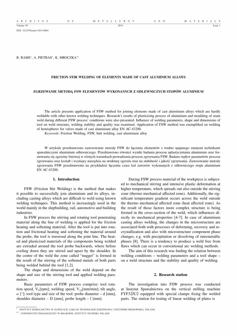
During testing the possibility of producing butt weld in6.0 mm thick plates of aluminium casting alloy EN AC 43200was investigated. The testing of the structure quality of a weldwas performed using a tool without a probe and of a shoulderdiameter D = 18 mm (α =1.5◦) and welding parameters as inTable 2. The example of this weld structure is shown in Fig. 3.
TABLE 2Welding parameters
No. Tool typeParameters of tool motionVn [rpm] Vzg[mm/min]
1Shoulder ø 18 mm,
without a probe
560 2242 560 1803 450 2244 450 180
Fig. 3. FSW weld structure. Welding parameters: no. 4 of Table. 2
Testing of conventional FSW butt welding process
Butt welding of cast plates of EN AC 43200 alloy, 6.0 mmthick, was conducted for parameters as in Table 3, usingconventional and Triflut tools (α =1.5◦). Below in Fig 4-5the examples of weld structures obtained during microscop-ic examination are shown. The welds were characterised bycompact structures without flaws and discontinuities visiblein macroscale. In photographs the advancing side is on theright.
TABLE 3Welding parameters
No. Tool typeParameters of tool motionVn [rpm] Vzg [mm/min]
1 Conventional 560 280
2 Conventional 710 355
3 Triflute 710 355
387
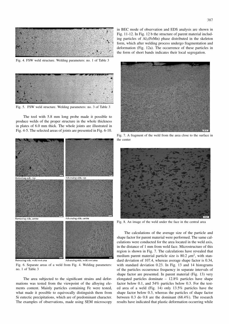
Fig. 4. FSW weld structure. Welding parameters: no. 1 of Table 3
Fig. 5. FSW weld structure. Welding parameters: no. 3 of Table 3
The tool with 5.8 mm long probe made it possible toproduce welds of the proper structure in the whole thicknessin plates of 6.0 mm thick. The whole joints are illustrated inFig. 4-5. The selected areas of joints are presented in Fig. 6-10.
Fig. 6. Separate areas of a weld from Fig. 4. Welding parameters:no. 1 of Table 3
The area subjected to the significant strains and defor-mations was tested from the viewpoint of the alloying ele-ments content. Mainly particles containing Fe were tested,what made it possible to equivocally distinguish them fromSi eutectic precipitations, which are of predominant character.The examples of observations, made using SEM microscopy
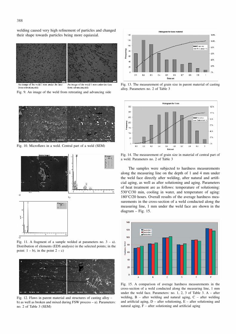
in BEC mode of observation and EDS analysis are shown inFig. 11-12. In Fig. 12 b the structure of parent material includ-ing particles of Al3(FeMn) phase distributed in the skeletonform, which after welding process undergo fragmentation anddeformation (Fig. 12a). The occurrence of these particles inthe form of short bands indicates their local segregation.
Fig. 7. A fragment of the weld from the area close to the surface inthe center
Fig. 8. An image of the weld under the face in the central area
The calculations of the average size of the particle andshape factor for parent material were performed. The same cal-culations were conducted for the area located in the weld axis,in the distance of 1 mm from weld face. Microstructure of thisregion is shown in Fig. 7. The calculations have revealed thatmedium parent material particle size is 80.2 µm2, with stan-dard deviation of 107.4, whereas average shape factor is 0.34,with standard deviation 0.23. In Fig. 13 and 14 histogramsof the particles occurrence frequency in separate intervals ofshape factor are presented. In parent material (Fig. 13) veryelongated particles dominate – 12.8% particles have shapefactor below 0.1, and 54% particles below 0.3. For the test-ed area of a weld (Fig. 14) only 13.5% particles have theshape factor below 0.3, whereas the particles of shape factorbetween 0.3 do 0.8 are the dominant (68.4%). The researchresults have indicated that plastic deformation occurring while
388
welding caused very high refinement of particles and changedtheir shape towards particles being more equiaxial.
Fig. 9. An image of the weld from retreating and advancing side
Fig. 10. Microflaws in a weld. Central part of a weld (SEM)
Fig. 11. A fragment of a sample welded at parameters no. 3 – a).Distribution of elements (EDS analysis) in the selected points; in thepoint: 1 – b), in the point 2 – c)
Fig. 12. Flaws in parent material and structures of casting alloy –b) as well as broken and mixed during FSW process – a). Parameters:no. 2 of Table 3 (SEM)
Fig. 13. The measurement of grain size in parent material of castingalloy. Parameters no. 2 of Table 3
Fig. 14. The measurement of grain size in material of central part ofa weld. Parameters no. 2 of Table 3
The samples were subjected to hardness measurementsalong the measuring line on the depth of 1 and 4 mm underthe weld face directly after welding, after natural and artifi-cial aging, as well as after solutioning and aging. Parametersof heat treatment are as follows: temperature of solutioning:530◦C/30 min, cooling in water, and temperature of aging:180◦C/20 hours. Overall results of the average hardness mea-surements in the cross-section of a weld conducted along themeasuring line, 1 mm under the weld face are shown in thediagram – Fig. 15.
Fig. 15. A comparison of average hardness measurements in thecross-section of a weld conducted along the measuring line, 1 mmunder the weld face. Parameters: no. 1, 2, 3 of Table 3. A – afterwelding, B – after welding and natural aging, C – after weldingand artificial aging, D – after solutioning, E – after solutioning andnatural aging, F – after solutioning and artificial aging
389
Testing of the process of welding valve balls parts
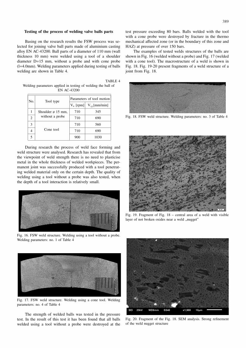
Basing on the research results the FSW process was se-lected for joining valve ball parts made of aluminium castingalloy EN AC-43200. Ball parts of a diameter of 110 mm (wallthickness 10 mm) were welded using a tool of a shoulderdiameter D=15 mm, without a probe and with cone probe(l=4.0mm). Welding parameters applied during testing of ballswelding are shown in Table 4.
TABLE 4Welding parameters applied in testing of welding the ball of
EN AC-43200
No. Tool typeParameters of tool motion
Vn [rpm] Vzg [mm/min]
1 Shoulder ø 15 mm,without a probe
710 345
2 710 690
3Cone tool
710 560
4 710 690
5 900 1030
During research the process of weld face forming andweld structure were analysed. Research has revealed that fromthe viewpoint of weld strength there is no need to plasticisemetal in the whole thickness of welded workpieces. The per-manent joint was successfully produced with a tool penetrat-ing welded material only on the certain depth. The quality ofwelding using a tool without a probe was also tested, whenthe depth of a tool interaction is relatively small.
Fig. 16. FSW weld structure. Welding using a tool without a probe.Welding parameters: no. 1 of Table 4
Fig. 17. FSW weld structure. Welding using a cone tool. Weldingparameters: no. 4 of Table 4
The strength of welded balls was tested in the pressuretest. In the result of this test it has been found that all ballswelded using a tool without a probe were destroyed at the
test pressure exceeding 80 bars. Balls welded with the toolwith a cone probe were destroyed by fracture in the thermomechanical affected zone (or in the boundary of this zone andHAZ) at pressure of over 150 bars.
The examples of tested welds structures of the balls areshown in Fig. 16 (welded without a probe) and Fig. 17 (weldedwith a cone tool). The macrostructure of a weld is shown inFig. 18. Fig. 19-20 present fragments of a weld structure of ajoint from Fig. 18.
Fig. 18. FSW weld structure. Welding parameters: no. 3 of Table 4
Fig. 19. Fragment of Fig. 18 – central area of a weld with visiblelayer of not broken oxides near a weld „nugget”
Fig. 20. Fragment of the Fig. 18. SEM analysis. Strong refinementof the weld nugget structure
390
Summary
The conducted tests made it possible to determine theinfluence of the tools on the process of friction weld formingduring butt welding of casting aluminium plates. The plateswere butt welded using a tool without a probe, conventionaltool and a tool of Triflute type.
Testing with a tool without a probe has revealed that atlow welding speed it is possible to obtain welds of compactstructure but the depth is small. For some applications suchweld thickness is sufficient. For instance the strength of theball welded in such a way and obtained in pressure test hasrevealed that the failure of the ball is caused only when thepressure was higher than 80 bar.
A weld formed correctly and of the adequate dimensionsand load capacity is produced while welding with a tool witha probe. Testing of a structure of butt joints in casting al-loys has revealed that the weld quality is higher of that ofparent material. Casting material contains higher or lower ag-glomerations of micro-shrinkages and discontinuities. Duringfriction welding many of these imperfections are eliminated.There are however micro-shrinkages in material of such a bigdimensions that even intensive thermal-plastic processing ofmaterial during FSW process fails to eliminate them.
Macroscopic structure of a weld is well visible as thematerial structure in the zone of thermo mechanical plas-ticisation undergoes transformation in the result of plasticstrain occurring with large degree of deformation. This zoneis not homogeneous. Basing on the particles distribution itis possible to determine the position of the so called weldnugget – central region in Fig. 6-8. The area covers approx-imately 30% of the whole zone of material thermal-plasticdeformation. Like in the typical FSW welds, the advancingside is characterised by the distinctly marked boundary be-tween the plastically deformed zone and heat affected zone(HAZ).
Weld microstructure testing has revealed that basing onthe distribution and size of particles it is possible to find thatthis boundary is the transition zone between material not plas-tically deformed and an area of strong deformation. In the tran-sition zone Si particles are mechanically fragmented (broken)but their distribution still remains the microstructure of castmaterial. The grains of the metallic matrix in this region areelongated accordingly to the direction of material transferringwhile welding and fail to undergo the processes of structurerenewal – recrystallization or recovery with the participationof subgrains coalescence process. The transition zone on theother side of a weld, i.e. on retreating side, is considerablywider what results in the less distinct boundary with HAZmaterial. Macrostructure analysis shows that the reaction ofa shoulder on its edges has limited influence on the weldstructure. The region of material deformation under the weldface surface occurs on the depth bigger than 1 mm only inthe distance of about 7.8 mm from weld axis. As the proberadius is relatively small (4 mm) the contact of material with ashoulder is in the distance of 9 mm, and the range of shoulderinteraction, as above, is 3.8 mm, which is about 42%. Sucha result implies that from the viewpoint of its reaction on theweld structure, the diameter of a shoulder can be smaller thanthat used currently.
In case of properly produced weld, in the jointcross-section there are no visible imperfections in all regionsof a joint. It is also possible to avoid the frequently occurringkissingbond defect.
One of the characteristic features of the majority of FSWjoints is the considerable diversification of the microstructure.In the separate regions of a weld the material is subjected tothe thermal-plastic treatment of various degrees. This concernsthe degree of the deformation, temperature of the deformationprocess as well as the distance of the material transport result-ing from the tool motion. On the basis of the comparison of theparticles size in parent and weld joint materials it is possibleto determine the degree of the material refinement. Welds incasting alloys are excellent for such analysis as precipitations,mainly Si, in the cast are of significant sizes and their shapesare elongated in the majority of cases. Thanks to this struc-ture feature it was possible to perform the calculations of theaverage particle size and the size factor for parent metal andfor the area located in the joint axis, in the distance of 1 mmfrom the weld face. The calculated average parent materialparticle size, of the average size factor 0.34, is 80.2 µm2. Inturn the average particle size in the analysed joint area (1 mmfrom the face, centre) is 12.4 µm2. This means that the plasticdeformation in this region caused 6-fold refinement of theparticles. The fragmentation of the particles simultaneouslycaused their shortening and changed the shape into more ovalone.
Macroscopic and microscopic analysis indicates the inho-mogeneity of the particles distribution in the separate microre-gions. The areas in the direct vicinity of the weld face revealthe substantial unification of the distribution in contrast withthe regions located closer to the weld nugget. The particlesbanding resulting from the direction of the material flow canalso be observed.
The testing of the welding region focused on the parti-cles containing Fe allowed for their unequivocal distinguishingfrom the dominant, eutectic Si precipitations. The particlescontaining Fe, Mn, Al (it is probably phase Al3(FeMn)), arearranged in short bands – the example of a band is marked asno. 1 in Fig. 12a. Such an arrangement of the particles in themicrostructure indicates their local segregation. The reasonsfor this segregation beyond any doubt are not associated withthe processes of diffusion and precipitation, and should belooked for in the way of plasticisation and displacement in thetested region. Testing of the parent material has revealed thepresence of the phase of the chemical composition analogicalto that which occurs locally in the form of the skeleton struc-tures. The example of this precipitation is shown in Fig. 12b(SEM-BEC observation). Chemical composition in both cas-es (in parent material and in the joint) was analysed usingSEM-EDS method. Such a result of the observation makes itpossible to conclude that material in the region above the weldnugget is subjected to the significant stresses and plastic flow,what causes particle fragmentation without the creation of amixture. For this reasons the skeleton structure of the phasewith Fe content being present in the parent material has beenbroken and transformed into the particles band visible in thejoint region being discussed (Fig. 12a). This conclusion alsobrings the explanation of the presence of micro-flaws in thetested area. The examples of imperfections are marked with
391
arrows in Fig. 12. Their origin is associated with the pres-ence of casting defects, so-called shrinkage porosity in parentmaterial. During welding process these flaws will behave likephases occurring locally. When material is not being mixedthey will only be deformed. State of stresses in the analysedpart of the joint and the range of material flow occurred to beinsufficient for the elimination (so-called recovery) of thoseimperfections. Their size however became significantly small-er. The imperfections in parent material, which sizes weresmaller, were eliminated by upsetting.
Testing of mechanical properties of butt welds producedin cast plates were confined to the determination of the hard-ness distribution. Hardness measurements were conducted inthe distance of 1 and 4 mm from the weld face of three samplesproduced at various welding parameters. Tests were performedfor weld testpieces being in three states: after welding, afterthe natural aging and after the artificial aging. The acquiredresults make it possible to conclude that the microstructuredirectly after welding is in the metastable state and over timeor as a result of the heat treatment undergoes changing, whichcauses hardening of material. This conclusion is confirmedalso by the results of the average hardness calculations per-formed on the basis of the separate hardness distributions.The average hardness of the weld in the state after weldingwas 73 HV0.1, after natural aging 82 HV0.1 and after artificialaging 99 HV0.1.
The process of natural aging causes distinct increase inmaterial hardness in the distance of –5 to +5 mm from thewelding line, thus in the range of tool probe action. In theremaining regions, in this case in the heat affected zone, thematerial hardness is similar to that of material being in thestate after welding and gradually increases with the distancefrom the welding line. The highest material hardness in thetested region was found for the joint after heat treatment, i.e.the artificial aging. The increase in hardness can be observedin the whole joint, and especially in the zone plastically de-formed, where the value of about 107 HV0.1 was noticed, i.e.by 37HV higher comparing to the state after welding. Probablyregardless of the distance from the weld face, material afterwelding will be hardening in the aging processes and the hard-ness increase reaches approximately 20% after natural agingand approximately 30% as a result of the artificial aging. Thedegree of material hardening depends on the place in the joint– the region being plastically processed is more susceptible toaging processes than heat affected zone.
Microstructure of the correct weld obtained during weld-ing of ball parts reveals the same features and characteristicstructures as that observed in the cross sections in butt welds.The structure of a weld is continuous and contains correctlyformed weld nugget. By design the ball parts were not weldedthrough the whole thickness of 10 mm, but only to the depthof 6 mm that was associated with the length of a tool probe.Therefore in the cross sections the oxides band is visible clear-ly, which is distributed in zigzag characteristic for FSW joints[5]. Such oxide inclusions do not reduce the joint strength.
Conclusions
On the basis of the research result analysis carried out atInstytut Spawalnictwa the following conclusions were drawn:• FSW process can be applied for joining components of
casting aluminium. Correctly selected welding parametersmake it possible to obtain good quality joints – withoutmacro and microscopic imperfections and of the requiredmechanical properties.
• In the region between the face and weld nugget the mater-ial is strongly deformed, what causes the refinement of theparticles, however simultaneously material is not mixed.
• In the FSW joint of casting material containing imperfec-tions, so called shrinkage porosity, submicron discontinu-ities of the microstructure can occur in the regions wherematerial is not mixed enough – e.g. in the area betweenthe face and weld nugget or in the zones boundary. Inthese regions the plastic distortion may fail to provide thefull elimination of such discontinuities.
• Plastic strain caused by a tool shoulder (under the facesurface) depends on welding parameters and a tool sizeand is very limited in the regions being more distant fromthe tool axis.
• During FSW process the microstructure of hypoeutecticsilumin in the regions close to weld face undergoes sig-nificant refinement due to mechanical fragmentation ofthe particles. The particles shape factor is also changingtowards more equiaxial one.
• Material of FSW joint, made in components of casting al-loy, directly after the welding process is in the metastablestate. As the result of both natural and artificial aging, thematerial in the weld regions undergoes hardening. Theprocess of the artificial aging is more effective and signif-icantly influences the hardening of material of the joint.
Acknowledgements
The article contains the selected research results obtained inthe project conducted within INNOTECH programme and entitled”Production of bimetallic components using advanced techniques offriction welding process” INNOTECH-K1/IN1/28/150092/NCBR/12,2012-2015.
REFERENCES
[1] W.M. T h o m a s, Friction Stir Butt Welding. Int. Patent Ap-plication. PCT/GB92/02203.1991
[2] K. M r o c z k a, J. D u t k i e w i c z, A. P i e t r a s, Charac-terization of friction stir welds of 6013 and 6013/2017A alu-minium alloy sheets. Inżynieria Materiałowa 30, 3 (2010).
[3] PN-EN 1706:2010. Aluminium i stopy aluminium – Odlewy –Skład chemiczny i własności mechaniczne.
[4] K. K r a s n o w s k i, P. S ę d e k, M. Ł o m o z i k, A.P i e t r a s, Impact of selected FSW parameters on mechanicalproperties of 6082-T6 aluminium alloy butt joints. Archives ofMetallurgy and Materials 56, 2011.
[5] H. O k a m u r a, K. A o t a, M. S a k a m o t o, Behaviourof oxides during friction stir welding of aluminium alloy andtheir effect on its mechanical properties. Welding International4, 2002.

392
[6] Y. M a t s u, K. O k a p i, Y. T a m a k i, Fatigue behaviourof dissimilar friction stir welds between cast and wrought alu-minium alloys. Strength of Materials 40, 1 (2008).
[7] M.S. W ę g l o w s k i, A. P i e t r a s, A. W ę g l o w s k a, Ef-fect of welding parameters on mechanical and microstructural
properties of Al 2024 joints produced by friction stir welding.Journal of Kones Powertrain and Transport 19, 1 (2009).
[8] G. L u a n, G. L i, W. W a n g, Ju K a n g, The FundamentalResearch of the Friction Flow Welding. The 8th InternationalFriction Stir Welding Symposium, Germany, 18-20 May 2010.
Received: 10 May 2013.