![THE MECHANICAL PROPERTIES AND MICROSTRUCTURES OF · PDF fileTHE MECHANICAL PROPERTIES AND MICROSTRUCTURES OF 9% CHROMIUM ... P91 would be possible [3] and secondly this value covers](https://static.fdocument.pub/doc/165x107/5aa91a997f8b9a9a188c64aa/the-mechanical-properties-and-microstructures-of-mechanical-properties-and-microstructures.jpg)
Formation and microstructures of unique nanoporous AAO films fabricated by high voltage anodization
6
Formation and microstructures of unique nanoporous AAO films fabricated by high voltage anodization Li Yi, Ling Zhiyuan, * Hu Xing, Liu Yisen and Chang Yi Received 22nd February 2011, Accepted 19th April 2011 DOI: 10.1039/c1jm10781j Nanoporous anodic aluminium oxide (AAO) films with a large-range tunable interpore distance (D int ) and unique microstructures have been fabricated by high voltage anodization (140–400 V) in 0.3 M oxalic acid electrolyte. The influences of anodization conditions (e.g., anodization voltage (U a ) and current density (i a )) on the microstructures of AAO films have been investigated in detail. Experimental results show that there is a linear relationship between U a and D int under relatively low U a . With the increase of U a , the influences of i a and dehydration of aluminium hydroxide on the D int may not be ignored, thus resulting in a nonlinear relationship between U a and D int . When the anodization is performed at an excessively high U a of 400 V, an interesting competitive growth of nanochannels inside the AAO film tends to occur, thus forming an AAO film with unique nano/micro morphology at the barrier layer side. 1. Introduction As a typical self-assembly material, nanoporous anodic aluminium oxide (AAO) films formed by the anodization process have been investigated for many years, 1–7 and have become one of the most commonly used templates for the fabrication of various nanostructured materials such as nanowires, nanotubes and nanopores, 8–11 since AAO films have a highly ordered 2D nanoporous array with controllable interpore distance (D int ), pore size (D pore ) and aspect ratio by varying the anodization conditions. 12–15 Clearly, the microstructural parameters of AAO films (e.g., D int and D pore ) will directly influence their performance in all these applications. Considering that the D pore can be adjusted and controlled by a further chemical etching process, and the maximum D pore is dependent on the D int , developing proper methods for the fabrication of AAO films with a large-range tunable D int has attracted much attention. 15–21 As we know, the D int of AAO films increases with the anodization voltage (U a ). 15–21 So performing the anodization under a U a as high as possible is an effective way to obtain a larger D int . In addition, high voltage anodization processes can also provide a faster AAO film growth rate and a wider self-organized window. 15–21 However, there are still some drawbacks in these processes: (1) under fixed anodization conditions (e.g., the voltage increasing process, electrolyte concentration and temperature), there is always an upper limit value of U a , over which the ‘‘burning and breakdown’’ phenomenon will occur during the voltage increasing process, 15 (2) the cell separation phenomenon easily occurs, resulting in a relatively weaker mechanical robustness of the as-prepared AAO film, 16,19,20 (3) the relationship between U a and D int is usually nonlinear, thus it is difficult to control the microstructural parameters of the AAO film. Therefore, finding proper methods for the fabrication of designated AAO films with accurately controllable microstructural parameters by high voltage anodization, is significant in both scientific research and commercial applications. In the present work, a simple and reliable approach is proposed for the fabrication of AAO films with a large-range tunable D int in 0.3 M oxalic acid electrolyte at a high U a of 140–400 V. By using an improved voltage increasing process, the ‘‘burning and breakdown’’ phenomenon can be effectively avoided. Based on the experimental results, the influences of anodization conditions (e.g., anodization voltage and current density (i a )) on the microstructural parameters of AAO films have been investigated in detail. To explain the AAO cell separation phenomenon and the nonlinear relationship between U a and D int , the formation and dehydration processes of aluminium hydroxide at the AAO cell walls have also been dis- cussed. Moreover, a new type of AAO film with a unique nano/ micro microstructure has also been realized via a competitive nanochannel growth process under an excessively high U a of 400 V, widening the potential applications of AAO films. 2. Experimental Highly pure aluminium sheets (99.99%) with a thickness of 1 mm were used as the starting materials. The sheets were electro- polished at 0–5 C and 21 V for 5 min in a mixture solution of perchloric acid and ethanol (1 : 4, v/v) to diminish the roughness Department of Electronic Materials Science and Engineering, College of Materials Science and Engineering, South China University of Technology, Guangzhou, 510640, People’s Republic of China. E-mail: [email protected]; Fax: +86 20 8711 1224; Tel: +86 20 8711 1224 This journal is ª The Royal Society of Chemistry 2011 J. Mater. Chem., 2011, 21, 9661–9666 | 9661 Dynamic Article Links C < Journal of Materials Chemistry Cite this: J. Mater. Chem., 2011, 21, 9661 www.rsc.org/materials PAPER Downloaded by University of Illinois at Chicago on 25 May 2012 Published on 27 May 2011 on http://pubs.rsc.org | doi:10.1039/C1JM10781J View Online / Journal Homepage / Table of Contents for this issue
Transcript of Formation and microstructures of unique nanoporous AAO films fabricated by high voltage anodization

Dynamic Article LinksC<Journal ofMaterials Chemistry
Cite this: J. Mater. Chem., 2011, 21, 9661
www.rsc.org/materials PAPER
Dow
nloa
ded
by U
nive
rsity
of
Illin
ois
at C
hica
go o
n 25
May
201
2Pu
blis
hed
on 2
7 M
ay 2
011
on h
ttp://
pubs
.rsc
.org
| do
i:10.
1039
/C1J
M10
781J
View Online / Journal Homepage / Table of Contents for this issue
Formation and microstructures of unique nanoporous AAO films fabricatedby high voltage anodization
Li Yi, Ling Zhiyuan,* Hu Xing, Liu Yisen and Chang Yi
Received 22nd February 2011, Accepted 19th April 2011
DOI: 10.1039/c1jm10781j
Nanoporous anodic aluminium oxide (AAO) films with a large-range tunable interpore distance (Dint)
and unique microstructures have been fabricated by high voltage anodization (140–400 V) in 0.3 M
oxalic acid electrolyte. The influences of anodization conditions (e.g., anodization voltage (Ua) and
current density (ia)) on the microstructures of AAO films have been investigated in detail. Experimental
results show that there is a linear relationship between Ua and Dint under relatively low Ua. With the
increase of Ua, the influences of ia and dehydration of aluminium hydroxide on the Dint may not be
ignored, thus resulting in a nonlinear relationship between Ua and Dint. When the anodization is
performed at an excessively highUa of 400 V, an interesting competitive growth of nanochannels inside
the AAO film tends to occur, thus forming an AAO film with unique nano/micro morphology at the
barrier layer side.
1. Introduction
As a typical self-assembly material, nanoporous anodic
aluminium oxide (AAO) films formed by the anodization process
have been investigated for many years,1–7 and have become one
of the most commonly used templates for the fabrication of
various nanostructured materials such as nanowires, nanotubes
and nanopores,8–11 since AAO films have a highly ordered 2D
nanoporous array with controllable interpore distance (Dint),
pore size (Dpore) and aspect ratio by varying the anodization
conditions.12–15
Clearly, the microstructural parameters of AAO films (e.g.,
Dint and Dpore) will directly influence their performance in all
these applications. Considering that the Dpore can be adjusted
and controlled by a further chemical etching process, and the
maximum Dpore is dependent on the Dint, developing proper
methods for the fabrication of AAO films with a large-range
tunable Dint has attracted much attention.15–21 As we know, the
Dint of AAO films increases with the anodization voltage
(Ua).15–21 So performing the anodization under a Ua as high as
possible is an effective way to obtain a larger Dint. In addition,
high voltage anodization processes can also provide a faster
AAO film growth rate and a wider self-organized window.15–21
However, there are still some drawbacks in these processes: (1)
under fixed anodization conditions (e.g., the voltage increasing
process, electrolyte concentration and temperature), there is
always an upper limit value of Ua, over which the ‘‘burning and
Department of Electronic Materials Science and Engineering, College ofMaterials Science and Engineering, South China University ofTechnology, Guangzhou, 510640, People’s Republic of China. E-mail:[email protected]; Fax: +86 20 8711 1224; Tel: +86 20 8711 1224
This journal is ª The Royal Society of Chemistry 2011
breakdown’’ phenomenon will occur during the voltage
increasing process,15 (2) the cell separation phenomenon easily
occurs, resulting in a relatively weaker mechanical robustness of
the as-prepared AAO film,16,19,20 (3) the relationship between Ua
and Dint is usually nonlinear, thus it is difficult to control the
microstructural parameters of the AAO film. Therefore, finding
proper methods for the fabrication of designated AAO films with
accurately controllable microstructural parameters by high
voltage anodization, is significant in both scientific research and
commercial applications. In the present work, a simple and
reliable approach is proposed for the fabrication of AAO films
with a large-range tunable Dint in 0.3 M oxalic acid electrolyte at
a high Ua of 140–400 V. By using an improved voltage increasing
process, the ‘‘burning and breakdown’’ phenomenon can be
effectively avoided. Based on the experimental results, the
influences of anodization conditions (e.g., anodization voltage
and current density (ia)) on the microstructural parameters of
AAO films have been investigated in detail. To explain the AAO
cell separation phenomenon and the nonlinear relationship
betweenUa andDint, the formation and dehydration processes of
aluminium hydroxide at the AAO cell walls have also been dis-
cussed. Moreover, a new type of AAO film with a unique nano/
micro microstructure has also been realized via a competitive
nanochannel growth process under an excessively high Ua of
400 V, widening the potential applications of AAO films.
2. Experimental
Highly pure aluminium sheets (99.99%) with a thickness of 1 mm
were used as the starting materials. The sheets were electro-
polished at 0–5 �C and 21 V for 5 min in a mixture solution of
perchloric acid and ethanol (1 : 4, v/v) to diminish the roughness
J. Mater. Chem., 2011, 21, 9661–9666 | 9661

Dow
nloa
ded
by U
nive
rsity
of
Illin
ois
at C
hica
go o
n 25
May
201
2Pu
blis
hed
on 2
7 M
ay 2
011
on h
ttp://
pubs
.rsc
.org
| do
i:10.
1039
/C1J
M10
781J
View Online
of their surface. Then the sheet was carefully washed and put into
a tailor-made holder with a square area of 1 cm2 exposed to the
electrolyte. Anodization was conducted in a 0.3 M oxalic acid
electrolyte at 0–5 �C and 140–400 V, with vigorous magnetic
stirring. A powerful low temperature bath, together with an
electrolysis cell (1 L) was used to maintain the low temperatures
required for the anodization. In addition, an improved voltage
increasing process was used: (1) the Ua was increased at a rate of
1 V s�1 until the ia reached 500 A m�2, (2) a constant-current
process was applied, by which the Ua can be smoothly increased
to the high target value (140–400 V), (3) the anodization was
conducted at a designated Ua with a constant-voltage mode. All
the obtained samples were immersed into a saturated CuCl2solution to remove the residual aluminium. The microstructures
of the as-prepared specimens were examined by a field-emission
scanning electron microscope (FE-SEM: LEO 1530 VP). The
anodization voltage and current were measured by multimeters
(Keithley 2010 and 2410).
Fig. 1 SEM images of the barrier layer side of highly ordered AAO films
fabricated in 0.3 M oxalic acid electrolyte (a) 140 V, 160 Am�2, (b) 165 V,
170 A m�2, (c) 190 V, 210 A m�2, (d) 215 V, 200 A m�2, (e) 260 V,
190 A m�2, (f) 310 V, 150 A m�2. Scale bars ¼ 300 nm.
Fig. 2 The evolution of average interpore distance (Dint) as a function of
anodization voltage (Ua). The data marked by filled black squares were
obtained in our experiment, corresponding to the samples shown in Fig. 1.
The datamarked by open black circles were proposed in ref. 15. The black
solid line represents the proportionality constant (z) of 2.0 nm V�1.
3. Results and discussion
3.1 Interpore distance of AAO films
3.1.1 The influence of Ua and ia. In the former studies, the
most commonly used AAO film fabricated in oxalic acid elec-
trolyte has been prepared at 40 V with a solution concentration
of 0.3 M.6 To suppress the burning and breakdown phenomenon
at a highUa (>100 V), Lee et al. found that the voltage increasing
process should be improved, and the maximum Ua can thus be
increased to 155 V in the same electrolyte.15Moreover, it was also
found that the ia plays an important role in the anodization
process.7,20–25 Generally speaking, ia can be divided into two
parts: ionic current density (ii) and electronic current density (ie).
The ii is used to form AAO and the ie can directly influence the
stability of the anodization process: the burning and breakdown
phenomenon will occur when the ie reaches a critical value.24
Considering that the ie is only a part of the ia (ia ¼ ii + ie), keeping
a steady ia is an effective way to obtain a controllable ie during
the initial voltage increasing process, thus avoiding the burning
and breakdown phenomenon under a high Ua. Accordingly,
a constant-current nonlinear voltage increasing process has been
performed in the present work, by which the maximumUa can be
successfully increased to 400 V in 0.3 M oxalic acid electrolyte.
Fig. 1 shows the SEM images of the barrier layer side of AAO
films fabricated under a Ua of 140–310 V with different ia. It can
be seen that their hexagonal structural cells are arranged with
a representative localized ordering, which has a similar
morphology to that reported before.15 In order to investigate the
influencing factors on the Dint, the evolution ofDint as a function
of Ua was measured (Fig. 2). In Fig. 2, it can be seen that the Dint
increases with the Ua, and the data proposed by Lee et al. (<140
V) agrees well with the proportionality constant (z) of 2.0 nm
V�1.15 However, it may only be a special case which occurs under
a special self-organized regime, depending on the anodization
conditions such as anodization voltage, current density and
electrolyte concentration. Obviously, the Dint obtained under
a Ua > 140 V shows a relatively gentle rise as the Ua increases. In
addition, the z exhibits a divergence under certain values of the
Ua. It was found that the Dint is not only dependent on the Ua,
9662 | J. Mater. Chem., 2011, 21, 9661–9666
but also influenced by the ia, and the corresponding equation can
be written as follows:20,21
Dint
Ua
¼ Aþ Be
�iaC : (1)
Where A, B and C are constants which are dependent on the
anodization conditions. According to eqn (1), the Dint and z will
This journal is ª The Royal Society of Chemistry 2011

Dow
nloa
ded
by U
nive
rsity
of
Illin
ois
at C
hica
go o
n 25
May
201
2Pu
blis
hed
on 2
7 M
ay 2
011
on h
ttp://
pubs
.rsc
.org
| do
i:10.
1039
/C1J
M10
781J
View Online
increase with the decrease of the ia. Therefore, it is not surprising
to see that the Dint obtained at 140 V in our experiment (160 A
m�2) is relatively larger than that reported before (230 A m�2).15
In addition, the divergence of the data that deviate from the
linear relationship of z ¼ 2.0 nm V�1 (<190 V) can also be well
elucidated by eqn (1). However, it can be seen that the z under the
condition of Ua > 215 V increases with the ia, which cannot be
reasonably elucidated by eqn (1), but may be ascribed to the
formation and dehydration of aluminium hydroxide at the AAO
cell walls during high voltage anodization.
3.1.2 The influence of hydroxide. It has been known that the
formation and dehydration of aluminium hydroxide (e.g., Al
(OH)3) during the high voltage anodization process can directly
influence the microstructural parameters of the as-prepared
AAO.19,26 In fact, a large amount of O2� and OH� can be
produced under a high enough Ua (Fig. 3a), according to the
hydrolysis equation shown as follows:7,14,25
Al2O3 þ nH2O/2Al3þ þ ð3þ n� xÞO2�
þxOH� þ ð2n� xÞHþ (2)
For these two types of anions, most of the O2� will be consumed
and released in the form of O2, due to the extremely high ieaccompanied by a high voltage anodization (Fig. 3b).24,26 As
a result, most of the Al3+ tends to combine with the OH� instead
of O2�, thus forming Al(OH)3 in the as-prepared AAO (Fig. 3b).
Considering that the dissociation energy of Al(OH)3 is relatively
small (3.80 kcal mol�1) and its dehydration reaction is endo-
thermic, Al(OH)3 will dehydrate easily and result in the forma-
tion of aluminium oxyhydroxide (AlOOH) under a high
temperature (i.e., high ia) accompanied by high voltage anod-
ization (Fig. 3c).19,26–28 This dehydration process will lead to the
volume contraction of the AAO cell walls, and a smaller Dint can
thus be obtained under the repulsive forces between the
Fig. 3 Schematic diagrams of the Al(OH)3 dehydration and volume
contraction process which occurs inside the AAO film during the high
voltage anodization process.
This journal is ª The Royal Society of Chemistry 2011
neighboring cells which are generated inside the AAO film during
the anodization process (Fig. 3c).29 It should be noted that more
Al(OH)3 can be formed and dehydrated under a higherUa during
high voltage anodization, thus resulting in a more apparent
volume contraction of the AAO cell walls. Accordingly, it is not
surprising to see that the z under the condition of Ua > 215 V
increases with the ia, but decreases with the Ua (Fig. 2), which
further means that the nonlinear relationship between Ua and
Dint caused by Ua cannot be ignored when a high enough Ua is
applied. In addition, a larger ia will lead to a higher temperature
in the AAO, thus resulting in a more apparent volume contrac-
tion and a smaller Dint under the same Ua (e.g., 140 V in Fig. 2).
According to this argument, the nonlinear relationship between
Ua and Dint caused by ia variation (i.e., eqn (1)) can also be well
explained.
3.2 A general growth model of AAO
In former studies, anodic aluminium oxide (AAO) and anodic
titanium oxide (ATO) are two nanoporous structural materials
which have been extensively studied in anodization processes. It
has been known that there are three representative morphologies
of the ATO: continuous nanoporous film, smooth separated
nanotubes and nanotubes with wall thickness variations.30,31 By
adjusting and controlling the anodization conditions, these
representative morphologies can also be realized and observed in
AAO.6,16,19,20,26 It is believed that the basic formation mecha-
nisms of AAO and ATO should be similar. However, it is still
difficult to reasonably explain the evolution of their micro-
structures and the z variation by using classical growth models
proposed before.27,29 Herein, we develop a general growth model
of AAO, and related schematic diagrams are shown in Fig. 4.
(I): In this type, the as-prepared AAO is formed as a ‘‘contin-
uous nanoporous film’’, usually corresponding to a relatively
lower Ua and ia. As a consequence, little Al(OH)3 is formed, and
the volume contraction caused by Al(OH)3 dehydration is rela-
tively slight. Therefore, a comparatively larger z of 2.5 nm V�1
can be obtained, which corresponds to the so called ‘‘mild
anodization’’ process.6,12,13With the increase ofUa, more O2� and
OH� can be produced, and more Al(OH)3 can be formed inside
the AAO film because of the increasing ie. As a result, a relatively
smaller z of approximately 2.0 nm V�1 can be obtained under the
coactions of Al(OH)3 dehydration (i.e., volume contraction) and
the repulsive forces between the neighboring cells inside the AAO
film, corresponding to the so called ‘‘hard anodization’’
process.15 It should be noted that in type I, most of the Al(OH)3 is
formed and dehydrated at the position near the pores instead of
the cell boundaries (see the arrows in Fig. 4a), since the migration
abilities of O2� and OH� are different.19,24,26 In this case, the as-
prepared AAO film is made up of anion-contaminated alumina
(near the pores) and relatively pure anion-free alumina (at the
cell boundaries),5,26,32,33 and the cleavage appears along the
pores.6,15
(II): In this type, the as-prepared AAO is formed as ‘‘smooth
separated nanotubes’’. With the further increase of Ua, most of
the O2� is consumed and released in the form of O2,24,26 and more
OH� can be driven by the extremely high electrical field to reach
the oxide/metal interface, thus forming an Al(OH)3 layer at the
cell boundaries.19,26 The dehydration of the Al(OH)3 layer will
J. Mater. Chem., 2011, 21, 9661–9666 | 9663

Fig. 4 Schematic diagrams of three representative morphologies of the
AAO: (a) Type I, continuous nanoporous film, (b) Type II, smooth
separated nanotubes, (c) Type III, nanotubes with wall thickness varia-
tions, the cell boundaries are marked by arrows shown in (a) and (b).
Fig. 5 SEM images of the AAO film fabricated in 0.3 M oxalic acid
electrolyte under a final Ua and ia of 400 V and 180 A m�2, respectively:
(a) the cross-sectional image of the upper and lower AAO films, (b)
a partially enlarged image of the fracture plane shown in (a), (c) the cross-
sectional image of the lower AAO film, (d) a partially enlarged image of
(c). Scale bars: 10 mm for (a), 1 mm for (b), 5 mm for (c), and 2 mm for (d).
Dow
nloa
ded
by U
nive
rsity
of
Illin
ois
at C
hica
go o
n 25
May
201
2Pu
blis
hed
on 2
7 M
ay 2
011
on h
ttp://
pubs
.rsc
.org
| do
i:10.
1039
/C1J
M10
781J
View Online
lead to volume contraction at the cell boundaries, resulting in the
formation of separated AAO nanotubes.16,19,20,26 Considering
that the Al(OH)3 layer is relatively thinner, the volume
contraction is slight, and separated AAO nanotubes with
a smooth external wall can be obtained.16,20 In this case, the
cleavage appears along the cell boundaries.16,20
(III): In this type, the as-prepared AAO is formed as ‘‘nano-
tubes with wall thickness variations’’. Compared with type II, the
Al(OH)3 layer at the cell boundaries is relatively thicker, and
the volume contraction is more apparent. Considering that the
direction of volume contraction of the Al(OH)3 layer can be
parallel to the growth direction of the AAO, separated AAO
nanotubes with wall thickness variations can be obtained, and
the cleavage also appears along the cell boundaries.19,26
Moreover, it is worth mentioning that the morphologies of the
AAO fabricated in different electrolyte systems are quite
different even under the same Ua. For example, under a Ua of
40 V, the AAO fabricated in oxalic acid and sulfuric acid elec-
trolytes will appear as ‘‘continuous nanoporous film’’ and
‘‘smooth separated nanotubes’’, respectively.6,16,20 Further
systematic studies are still needed to improve this general growth
model of AAO from a qualitative model to a quantitative one.
3.3 Unique nanoporous AAO films
Interestingly, a phenomenon accompanied by high voltage
anodization can be observed under the condition that a high
9664 | J. Mater. Chem., 2011, 21, 9661–9666
enough Ua is applied. Fig. 5 shows the SEM images of the AAO
film fabricated under a final Ua and ia of 400 V and 180 A m�2 in
0.3 M oxalic acid electrolyte. Apparently, a fracture plane can be
observed, and the AAO film is divided into two parts (Fig. 5a). It
can be seen that the bottom side of the upper AAO film is rela-
tively smooth, which has a similar morphology with that fabri-
cated via traditional anodization processes (Fig. 5a).6,12,13
However, the lower AAO film exhibits a novel morphology: its
barrier layer surface is rough, and made up of many microscale
(10–30 mm) hemispherical structures. Fig. 5b shows a partially
enlarged image of the fracture plane in Fig. 5a. It can be seen that
the AAO film at the fracture plane is made up of separated AAO
nanotubes (the circular region in Fig. 5b). Fig. 5c–d shows the
partially enlarged images of the lower AAO film shown in
Fig. 5a. It can be seen that each hemispherical structure consists
of many nanochannels developed in radial directions (Fig. 5c–d),
and branched nanochannels can also be observed (Fig. 5d), thus
resulting in a novel nano/micro structure. Fig. 6 shows the cross-
sectional schematic diagram of the AAO film shown in Fig. 5.
To explain these experimental phenomena one may examine
the Ua and ia transients during the anodization process (Fig. 7).
Apparently, two modes are applied in the whole anodization
process: first, a constant current (CC) mode is used during the
voltage increasing process, thus obtaining a high enough Ua, and
then a constant voltage (CV) mode is performed for the fabri-
cation of the AAO film under designated Ua and ia. In addition,
apparent oscillations of the Ua and ia can be observed during the
CC and CV modes, respectively. Similar phenomena can also be
observed in our former research.19,26 Moreover, the ia–time
transients show a decrease as a function of the anodization time,
which can be explained by the diffusion-limited anodization at
the pore bottom.15
Based on the experimental results and above arguments, the
formation process of the AAO film shown in Fig. 5 can be
illustrated as follows. At a certain stage of the voltage increasing
This journal is ª The Royal Society of Chemistry 2011
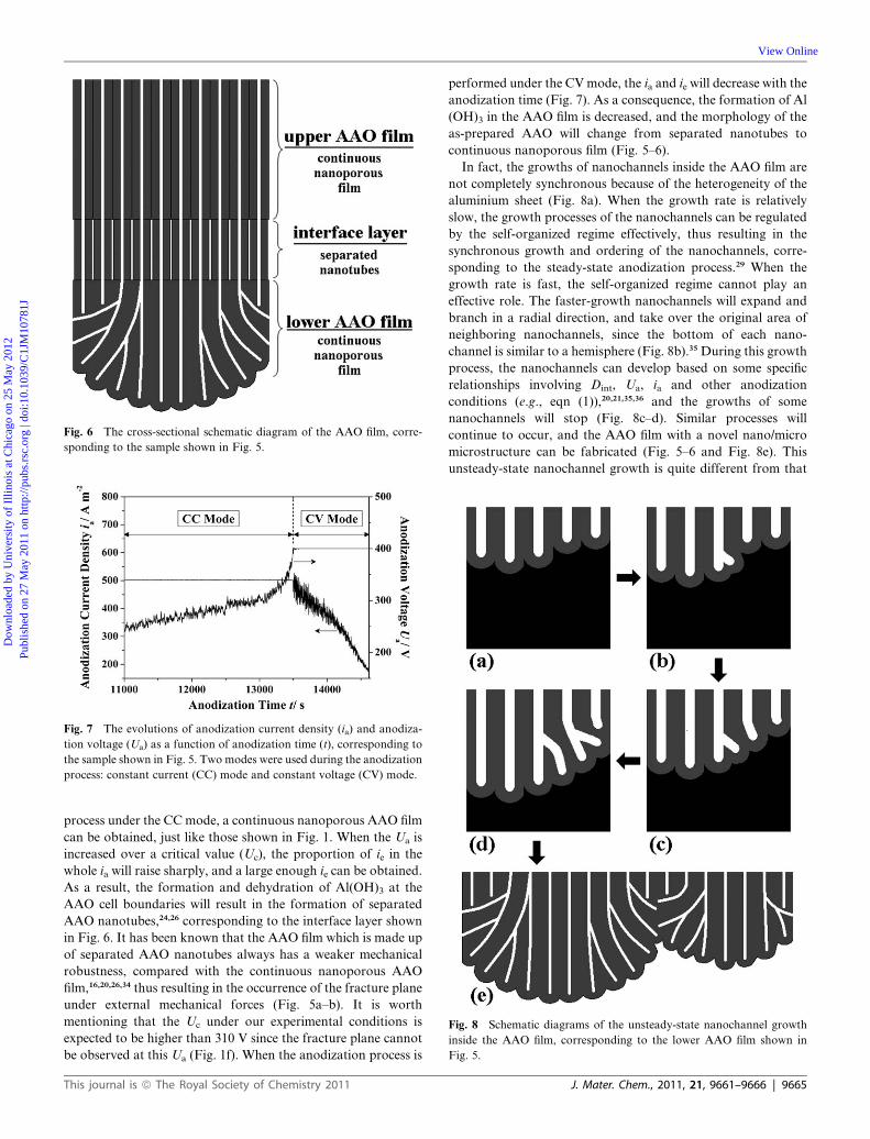
Fig. 6 The cross-sectional schematic diagram of the AAO film, corre-
sponding to the sample shown in Fig. 5.
Fig. 7 The evolutions of anodization current density (ia) and anodiza-
tion voltage (Ua) as a function of anodization time (t), corresponding to
the sample shown in Fig. 5. Two modes were used during the anodization
process: constant current (CC) mode and constant voltage (CV) mode.
Fig. 8 Schematic diagrams of the unsteady-state nanochannel growth
inside the AAO film, corresponding to the lower AAO film shown in
Fig. 5.
Dow
nloa
ded
by U
nive
rsity
of
Illin
ois
at C
hica
go o
n 25
May
201
2Pu
blis
hed
on 2
7 M
ay 2
011
on h
ttp://
pubs
.rsc
.org
| do
i:10.
1039
/C1J
M10
781J
View Online
process under the CCmode, a continuous nanoporous AAO film
can be obtained, just like those shown in Fig. 1. When the Ua is
increased over a critical value (Uc), the proportion of ie in the
whole ia will raise sharply, and a large enough ie can be obtained.
As a result, the formation and dehydration of Al(OH)3 at the
AAO cell boundaries will result in the formation of separated
AAO nanotubes,24,26 corresponding to the interface layer shown
in Fig. 6. It has been known that the AAO film which is made up
of separated AAO nanotubes always has a weaker mechanical
robustness, compared with the continuous nanoporous AAO
film,16,20,26,34 thus resulting in the occurrence of the fracture plane
under external mechanical forces (Fig. 5a–b). It is worth
mentioning that the Uc under our experimental conditions is
expected to be higher than 310 V since the fracture plane cannot
be observed at this Ua (Fig. 1f). When the anodization process is
This journal is ª The Royal Society of Chemistry 2011
performed under the CVmode, the ia and ie will decrease with the
anodization time (Fig. 7). As a consequence, the formation of Al
(OH)3 in the AAO film is decreased, and the morphology of the
as-prepared AAO will change from separated nanotubes to
continuous nanoporous film (Fig. 5–6).
In fact, the growths of nanochannels inside the AAO film are
not completely synchronous because of the heterogeneity of the
aluminium sheet (Fig. 8a). When the growth rate is relatively
slow, the growth processes of the nanochannels can be regulated
by the self-organized regime effectively, thus resulting in the
synchronous growth and ordering of the nanochannels, corre-
sponding to the steady-state anodization process.29 When the
growth rate is fast, the self-organized regime cannot play an
effective role. The faster-growth nanochannels will expand and
branch in a radial direction, and take over the original area of
neighboring nanochannels, since the bottom of each nano-
channel is similar to a hemisphere (Fig. 8b).35 During this growth
process, the nanochannels can develop based on some specific
relationships involving Dint, Ua, ia and other anodization
conditions (e.g., eqn (1)),20,21,35,36 and the growths of some
nanochannels will stop (Fig. 8c–d). Similar processes will
continue to occur, and the AAO film with a novel nano/micro
microstructure can be fabricated (Fig. 5–6 and Fig. 8e). This
unsteady-state nanochannel growth is quite different from that
J. Mater. Chem., 2011, 21, 9661–9666 | 9665

Dow
nloa
ded
by U
nive
rsity
of
Illin
ois
at C
hica
go o
n 25
May
201
2Pu
blis
hed
on 2
7 M
ay 2
011
on h
ttp://
pubs
.rsc
.org
| do
i:10.
1039
/C1J
M10
781J
View Online
which occurs in conventional steady-state anodization
processes,6,12,13 but similar to the ‘‘competitive nanochannel
growth’’ reported before.35,37 It worth mentioning that such
a nano/micro AAO structure has rarely been reported in former
investigations, and may have diverse potential applications in
many fields, such as filters, superhydrophobic surfaces, etc.
4. Conclusions
In summary, nanoporous anodic aluminium oxide (AAO) films
with diverse microstructures and a large-range tunable interpore
distance (Dint) have been fabricated in 0.3 M oxalic acid elec-
trolyte under an anodization voltage (Ua) of 140–400 V. The
relationship between AAO microstructural parameters and
anodization conditions has been investigated in detail. Experi-
mental results show that both the Ua and anodization current
density (ia) can lead to the nonlinear relationship betweenUa and
Dint. The formation and dehydration of Al(OH)3 inside the AAO
film can play a very important role during the high voltage
anodization process, thus resulting in AAO films with diverse
microstructures (e.g., continuous nanoporous AAO film or
separated AAO nanotubes). In addition, the AAO film with
a novel nano/micro microstructure has been fabricated under
aUa of 400 V via an unsteady-state nanochannel growth process.
The AAO films obtained in this approach may have important
use in many related fields, and similar methods may also be
applied in other electrolyte systems to fabricate AAO films with
diverse microstructures.
Acknowledgements
This work was supported by the Fundamental Research Funds
for the Central Universities (2009ZM0095), the China Post-
doctoral Science Foundation funded project (20100470913), and
the Doctoral Fund of Ministry of Education of China
(20100172110011).
References
1 F. Keller, M. S. Hunter and D. L. Robinson, J. Electrochem. Soc.,1953, 100, 411.
2 J. W. Diggle, T. C. Downie and C. W. Goulding, Chem. Rev., 1969,69, 365.
3 J. P. O’Sullivan and G. C. Wood, Proc. R. Soc. London, Ser. A, 1970,317, 511.
4 G. E. Thompson, R. C. Furneaux, G. C. Wood, J. A. Richardson andJ. S. Goode, Nature, 1978, 272, 433.
9666 | J. Mater. Chem., 2011, 21, 9661–9666
5 G. E. Thompson and G. C. Wood, Nature, 1981, 290, 230.6 H. Masuda and K. Fukuda, Science, 1995, 268, 1466.7 Z. X. Su, G. H€ahner andW. Z. Zhou, J.Mater. Chem., 2008, 18, 5787.8 Y. Li, G.W.Meng and L. D. Zhang,Appl. Phys. Lett., 2000, 76, 2011.9 L. Zhao, M. Yosef, M. Steinhart, P. G€oring, H. Hofmeister,U. G€osele and S. Schlecht, Angew. Chem., Int. Ed., 2006, 45, 311.
10 G. Q. Ding, W. Z. Shen, M. J. Zheng and D. H. Fan, Appl. Phys.Lett., 2006, 88, 103.
11 Z. Y. Ling, S. S. Chen, J. C.Wang andY. Li,Chin. Sci. Bull., 2008, 53,183.
12 A. P. Li, F. M€uller, A. Birner, K. Nielsch and U. G€osele, J. Appl.Phys., 1998, 84, 6023.
13 K. Nielsch, J. Choi, K. Schwirn, R. B. Wehrspohn and U. G€osele,Nano Lett., 2002, 2, 677.
14 Z. X. Su and W. Z. Zhou, J. Mater. Chem., 2011, 21, 357.15 W. Lee, R. Ji, U. G€osele and K. Nielsch, Nat. Mater., 2006, 5, 741.16 S. Z. Chu, K. Wada, S. Inoue, M. Isogai and A. Yasumori, Adv.
Mater., 2005, 17, 2115.17 Y. B. Li, M. J. Zheng and L. Ma, Appl. Phys. Lett., 2007, 91, 073109.18 Y. Li, Z. Y. Ling, J. C. Wang, S. S. Chen, X. Hu and X. H. He, Chin.
Sci. Bull., 2008, 53, 1608.19 Y. Li, Z. Y. Ling, S. S. Chen, X. Hu and X. H. He, Chem. Commun.,
2010, 46, 309.20 Y. Li, Z. Y. Ling, S. S. Chen and J. C. Wang, Nanotechnology, 2008,
19, 225604.21 Y. B. Li, M. J. Zheng, L. Ma and W. Z. Shen, Nanotechnology, 2006,
17, 5101.22 S. Ono,M. Saito andH. Asoh,Electrochem. Solid-State Lett., 2004, 7,
B21.23 S. Ono, M. Saito, M. Ishiguro and H. Asoh, J. Electrochem. Soc.,
2004, 151, B473.24 X. F. Zhu, Y. Song, L. Liu, C. Y. Wang, J. Zheng, H. B. Jia and
X. L. Wang, Nanotechnology, 2009, 20, 475303.25 Z. X. Su, M. B€uhl and W. Z. Zhou, J. Am. Chem. Soc., 2009, 131,
8697.26 Y. Li, Z. Y. Ling, X. Hu, Y. S. Liu and Y. Chang, Chem. Commun.,
2011, 47, 2173.27 Z. X. Su and W. Z. Zhou, Adv. Mater., 2008, 20, 3663.28 F. Le Coz, L. Arurault, S. Fontorbes, V. Vilar, L. Datas and
P. Winterton, Surf. Interface Anal., 2010, 42, 227.29 O. Jessensky, F. M€uller and U. G€osele, Appl. Phys. Lett., 1998, 72,
1173.30 Y. Shin and S. Lee, Nano Lett., 2008, 8, 3171.31 J. M. Macak, H. Tsuchiya, L. Taveira, S. Aldabergerova and
P. Schmuki, Angew. Chem., Int. Ed., 2005, 44, 7463.32 J. J. Schneider, J. Engstler, K. P. Budna, C. Teichert and S. Franzka,
Eur. J. Inorg. Chem., 2005, 2352.33 J. Choi, Y. Luo, R. B. Wehrspohn, R. Hillebrand, J. Schilling and
U. G€osele, J. Appl. Phys., 2003, 94, 4757.34 W. Lee, R. Scholz and U. G€osele, Nano Lett., 2008, 8, 2155.35 S. S. Chen, Z. Y. Ling, X. Hu, H. Yang and Y. Li, J. Mater. Chem.,
2010, 20, 1794.36 S. S. Chen, Z. Y. Ling, X. Hu and Y. Li, J. Mater. Chem., 2009, 19,
5717.37 H. Takahashi, M. Nagayama, H. Akahori and A. Kitahara, J.
Electron Microsc., 1973, 22, 149.
This journal is ª The Royal Society of Chemistry 2011