flexiBrute 1.0 MIDI Interface - Eastern Voltage Research · Let your soldering iron tip gently heat...
37
flexiBrute 1.0 MIDI Interface April 2014, Rev A − 1 − http://www.EasternVoltageResearch.com flexiBrute 1.0 MIDI Interface Instruction Manual f f l l e e x x i i B B r r u u t t e e 1 1 . . 0 0 M M I I D D I I I I n n t t e e r r f f a a c c e e I I n n s s t t r r u u c c t t i i o o n n M M a a n n u u a a l l Eastern Voltage Research, LLC
-
Upload
truongnguyet -
Category
Documents
-
view
217 -
download
1
Transcript of flexiBrute 1.0 MIDI Interface - Eastern Voltage Research · Let your soldering iron tip gently heat...

flexiBrute 1.0 MIDI Interface
April 2014, Rev A − 1 − http://www.EasternVoltageResearch.com flexiBrute 1.0 MIDI Interface Instruction Manual
fflleexxiiBBrruuttee 11..00 MMIIDDII IInntteerrffaaccee
IInnssttrruuccttiioonn MMaannuuaall
EEaasstteerrnn VVoollttaaggee RReesseeaarrcchh,, LLLLCC

flexiBrute 1.0 MIDI Interface
April 2014, Rev A − 2 − http://www.EasternVoltageResearch.com flexiBrute 1.0 MIDI Interface Instruction Manual
Introduction to the flexiBrute 1.0 MIDI Interface
Thank you for purchasing the flexiBrute 1.0 MIDI Interface. This kit has been one of our
most requested Tesla Coil related kits and we are excited to finally bring it to you. What
this kit provides is an easy way to convert your existing or your new Solid State Tesla
Coil (SSTC) or Double Resonant Solid State Tesla Coil (DRSSTC) into a musical
instrument. In otherwords, by connecting a keyboard or other compatible MIDI based
instrument or sound source, you can use your Tesla Coil to generate musical tones. For
example, if you play a MIDDLE C on your electronic keyboard, your Tesla Coil will be
pulsed at the MIDDLE C frequency of 261 Hz and you will hear that audio frequency of
261 Hz. Pretty neat, eh? Our monophonic version will allow one to play single notes
with their Tesla Coil while our polyphonic version will allow you to play two
simultaneous notes! The ability to play more than one note at a time on your Tesla Coil
will definitely up the coolness factor significantly.
The flexiBrute 1.0 MIDI Interface is designed to be used for virtually any solid state
Tesla Coil. It will work with the smallest SSTCs as well as the largest DRSSTCs which
could be using full-bridge switching configurations of high power CM600 IGBT bricks.
The flexiBrute 1.0 MIDI Interface is fully customizable by the end user and can be
configured very easily for practically any Tesla coil application.
This kit is also directly compatible with our microBrute and miniBrute line of DRSSTCs.
Please read this manual in its entirety before building, testing, or operating your kit!

flexiBrute 1.0 MIDI Interface
April 2014, Rev A − 3 − http://www.EasternVoltageResearch.com flexiBrute 1.0 MIDI Interface Instruction Manual
Kit Building Tips
A good soldering technique is key! Let your soldering iron tip gently heat both the wires
and pads simultaneously. Apply solder to the wire and the pad when the pad is hot
enough to melt the solder. The finished joint should appear like a small shiny drop of
water on paper, somewhat soaked in. If the pads have not heated up sufficiently, melted
solder (heated only by the soldering iron itself) will form a cold solder joint and will not
conduct properly. These cold joints appear as dull beads of solder, and can be easily
fixed by applying additional heat to the pad and wire. All components, unless otherwise
noted, should be mounted on the top side of the board. This is the side with the
silkscreen printing.
When installing components, the component is placed flat to the board and the leads are
bent on the backside of the board to prevent the part from falling out before soldering.
The part is then soldered securely to the board, and the remaining lead length is clipped
off. It is also extremely important to place the components as close to the board as
possible. This is necessary for proper operation over the wide frequency range of the
various kits we provide. Also be sure that component lead lengths are always as short as
possible. This will avoid adding any stray capacitances or inductances that can be
detrimental to circuit operation.
An alternative approach (which is actually the one I use) is to install the component into
the board and then apply a piece of masking tape on the topside to the hold the
component in place temporarily. The leads on the backside of the board are then trimmed
leaving about 0.10” lead protruding through the backside of the board, and then soldered
from the backside. You can then remove the masking tape, and finally apply a small
amount of solder on the top to complete the joint on both sides. This is shown in the
figure below.

flexiBrute 1.0 MIDI Interface
April 2014, Rev A − 4 − http://www.EasternVoltageResearch.com flexiBrute 1.0 MIDI Interface Instruction Manual
flexiBrute 1.0 MIDI Interface Parts List
RESISTORS
� 4 10k Resistor (brown-black-orange), R3, R4, R5, R6
� 2 560 Resistor (green-blue-brown), R7, R21
� 1 100 Resistor (brown-black-brown), R8
� 1 470 Resistor (yellow-violet-brown), R10
� 1 220 Resistor (red-red-brown), R11
� 1 56 Resistor (green-blue-black), R12
� 2 120 Resistor (brown-red-brown), R13,R14
� 2 1k Resistor (brown-black-red), R15,R16
� 2 Potentiometer, 100k (marking 104), R1,R2
� 1 Potentiometer, 1Meg (marking 105), R9
CAPACITORS
� 2 22pF Capacitor, Ceramic, C1,C2
� 10 0.1uF Capacitor, Ceramic, C3,C4,C5,C6,C8,C9,C10,C11,C21,C22
� 1 0.01uF Capacitor, Ceramic, C7
� 1 10uF, 50V Capacitor, Electrolytic, C12
� 1 1000uF, 10V Capacitor, Electrolytic, C23
DIODES
� 1 Diode, 1N4002, CR21
� 2 Diode, 1N4148, CR1,CR2
� 4 LED, T-1, Blue, D1,D2,D3,D21
SEMICONDUCTORS
� 1 Microcontroller, flexiBrute 1.0 MIDI, 28-Pin, U1
� 1 HCPL2601 Optoisolator, U2
� 1 SN74LS123 Multivibrator, U3
� 1 SN74HC08 Quad 2-Input AND Gate, U4
� 1 TC4427 Gate Driver, U5 � 1 LM7805 Voltage Regulator, U21
� 1 Crystal Oscillator, 16MHz, XTAL1

flexiBrute 1.0 MIDI Interface
April 2014, Rev A − 5 − http://www.EasternVoltageResearch.com flexiBrute 1.0 MIDI Interface Instruction Manual
MISCELLANEOUS
� 1 MIDI, 5-Pin Connector, J1
� 1 RCA Connector, Female, J2A (See Note 1)
� 1 BNC Connector, Female, J2B (See Note 1)
� 1 Fiber Optic Connector, HFBR1412, J3 (See Note 1)
� 1 DIP Switch, 4-Position, SW1
� 1 Terminal Block, 2-Position, TB1
� 1 IC Socket, 28-Pin DIP, U21
� 1 flexiBrute 1.0 MIDI PCB Board
� 1 flexiBrute 1.0 MIDI Schematic
Note 1: The type of connector supplied with the kit is dependent on the particular kit you ordered.
REQUIRED, NOT SUPPLIED
� 1 Power Supply, 9V, 1A (or similar)
OPTIONAL, BUT RECOMMENDED
� 1 16-Pin DIP Socket (See note 2)
� 1 14-Pin DIP Socket (See note 2)
� 2 8-Pin DIP Socket (See note 2)
� 1 Speaker, 8 ohm, Small (See note 3)
Note 2: The use of DIP sockets is not required, but it is recommended. Using DIP sockets for each and
every IC will allow easy removal for troubleshooting and repair. DIP sockets may be purchased from any
electronics supplier, including your local Radio Shack or similar electronics store, or can be purchased
directly from us at our website under the components ordering pages.
Note 3: The use of a small 8 ohm speaker is beneficial as it allows you to test the operation of your MIDI keyboard or similar equipment with your MIDI interface board. We recommend any small 8-ohm speaker.
These are the small speakers typically found in computer cases or other small radios or toys. We also offer
these speakers on our flexiBrute MIDI Interface website ordering page.
flexiBrute 1.0 MIDI Interface
April 2014, Rev A − 6 − http://www.EasternVoltageResearch.com flexiBrute 1.0 MIDI Interface Instruction Manual
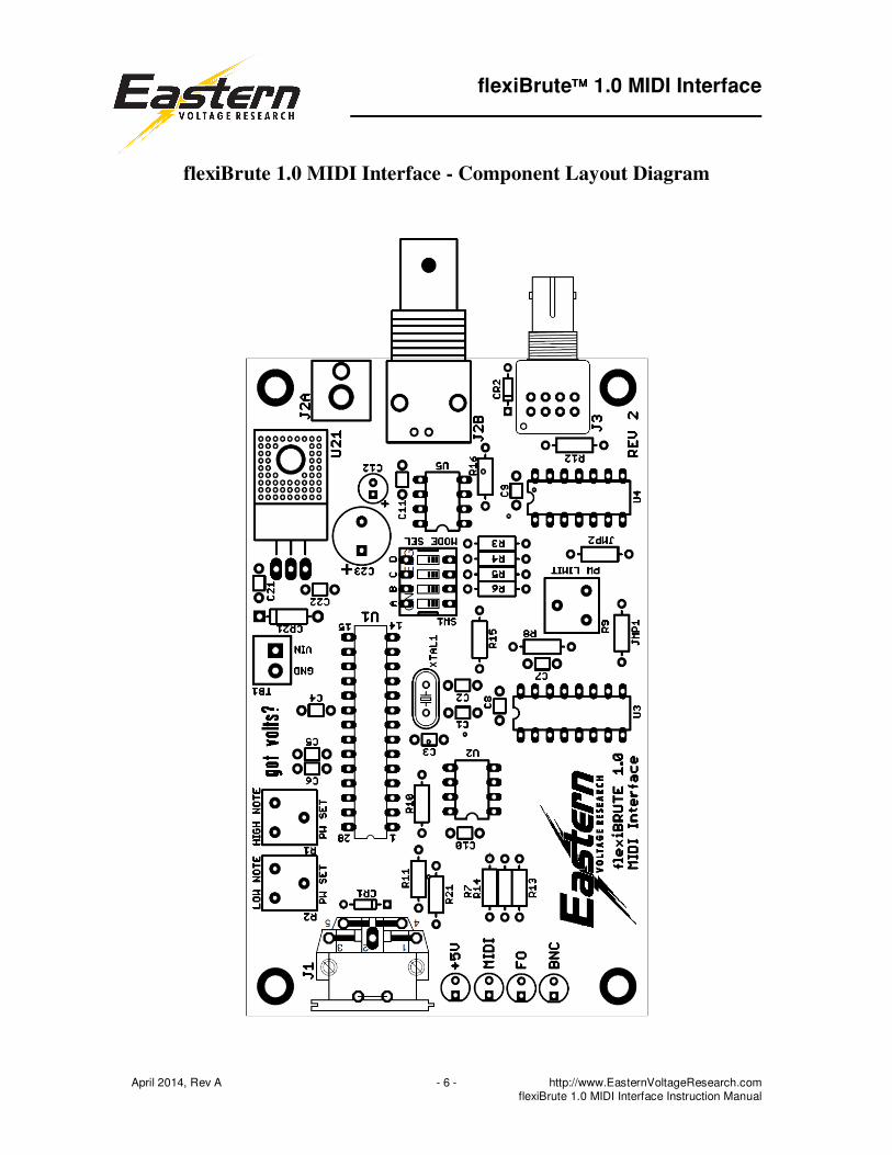
flexiBrute 1.0 MIDI Interface - Component Layout Diagram

flexiBrute 1.0 MIDI Interface
April 2014, Rev A − 7 − http://www.EasternVoltageResearch.com flexiBrute 1.0 MIDI Interface Instruction Manual
flexiBrute 1.0 MIDI Interface – Mounting Provisions
Your flexiBrute 1.0 MIDI Interface can be mounted directly to any flat surface using the
four (4) mounting holes as shown above. Each mounting hole accepts #6 hardware and
we recommend using 6-32 stand-offs and 6-32 screws to mount the board.

flexiBrute 1.0 MIDI Interface
April 2014, Rev A − 8 − http://www.EasternVoltageResearch.com flexiBrute 1.0 MIDI Interface Instruction Manual
KIT Building Instructions
Now we will begin building the kit. There are just a few more important things to know
before we install the first components.
For each component, the word “install” always means the following:
1. Pick the correct value to start with.
2. Insert the component into the correct printed circuit board (PCB) location.
3. Orient the component correctly – especially when there is a right and a wrong
way to solder it in. (i.e. Electrolytic capacitors, diodes, ICs, transistors, etc…)
4. Solder all connections unless directed otherwise. Ensure enough heat is used to
allow solder to flow for clean, shiny, and completed connections.
Also, please be sure to take us seriously when we say that good soldering is the key to the
proper operation of your circuit!
• Use a 25W soldering pencil with a clean, sharp tip. DO NOT USE a high power
soldering gun such as those trigger activated units.
• Use only rosin core solder intended for electronics use
• Ensure your work area is clean, and has plenty of bright lighting
• Build your kit in stages, taking breaks to check your work. Be sure to clean the
board periodically with a brush or compressed air to remove any excess wire
cuttings, etc…
Okay, so lets begin!
� 1. Install JMP2, zero ohm resistor (one black stripe) or jumper wire
� 2. Install R3, 10k resistor (brown-black-orange)
� 3. Install R4, 10k resistor (brown-black-orange)
� 4. Install R5, 10k resistor (brown-black-orange)
� 5. Install R6, 10k resistor (brown-black-orange)
� 6. Install R7, 560 resistor (green-blue-brown)
� 7. Install R21, 560 resistor (green-blue-brown)
� 8. Install R8, 100 resistor (brown-black-brown)

flexiBrute 1.0 MIDI Interface
April 2014, Rev A − 9 − http://www.EasternVoltageResearch.com flexiBrute 1.0 MIDI Interface Instruction Manual
� 9. Install R10, 470 resistor (yellow-violet-brown)
� 10. Install R11, 220 resistor (red-red-brown)
� 11. Install R12, 56 resistor (green-blue-black)
� 12. Install R13, 120 resistor (brown-red-brown)
� 13. Install R14, 120 resistor (brown-red-brown)
� 14. Install R15, 1k resistor (brown-black-red)
� 15. Install R16, 1k resistor (brown-black-red)
� 16. Install CR1, 1N4148 diode. The cathode band on the diode must match that
shown on the silkscreen.
� 17. Install CR2, 1N4148 diode. The cathode band on the diode must match that
shown on the silkscreen.
� 18. Install CR21, 1N4002 diode. The cathode band on the diode must match that
shown on the silkscreen.
� 19. Install D1, Blue LED (smaller LED provided in the kit). The short lead of the
diode is the cathode and will install into the square pad on the PCB board.
� 20. Install D2, Blue LED (smaller LED provided in the kit). The short lead of the
diode is the cathode and will install into the square pad on the PCB board.
� 21. Install D3, Blue LED (smaller LED provided in the kit). The short lead of the
diode is the cathode and will install into the square pad on the PCB board.
� 22. Install D21, Blue LED (smaller LED provided in the kit). The short lead of
the diode is the cathode and will install into the square pad on the PCB board.
� 23. Install C1, 22pF capacitor (marking BC22 or 22J)
� 24. Install C2, 22pF capacitor (marking BC22 or 22J)
� 25. Install C3, 0.1uF capacitor (marking BC104 or 104)
� 26. Install C4, 0.1uF capacitor (marking BC104 or 104)

flexiBrute 1.0 MIDI Interface
April 2014, Rev A − 10 − http://www.EasternVoltageResearch.com flexiBrute 1.0 MIDI Interface Instruction Manual
� 27. Install C5, 0.1uF capacitor (marking BC104 or 104)
� 28. Install C6, 0.1uF capacitor (marking BC104 or 104)
� 29. Install C8, 0.1uF capacitor (marking BC104 or 104)
� 30. Install C9, 0.1uF capacitor (marking BC104 or 104)
� 31. Install C10, 0.1uF capacitor (marking BC104 or 104)
� 32. Install C11, 0.1uF capacitor (marking BC104 or 104)
� 33. Install C21, 0.1uF capacitor (marking BC104 or 104)
� 34. Install C22, 0.1uF capacitor (marking BC104 or 104)
� 35. Install C7, 0.01uF capacitor (marking BC103 or 103)
� 36. Install 28-Pin DIP Socket in the U1 location. Note that one end of the DIP
Socket is marked by a dot, notch, or band; this end MUST be oriented as shown
on the PCB layout.
� 37. Install U2, HCPL2601 Optoisolator (marking 2601). The HCPL2601 may be
soldered directly to the PCB without worry, but you may use an 8-pin DIP socket
(not supplied) if you prefer as this would aid in troubleshooting and repair. Note
that one end of the IC is marked by a dot, notch, or band; this end MUST be
oriented as shown on the PCB layout.
� 38. Install U3, SN74LS123 Multivibrator. The SN74LC123 may be soldered
directly to the PCB without worry, but you may use an 16-pin DIP socket (not
supplied) if you prefer as this would aid in troubleshooting and repair. Note that
one end of the IC is marked by a dot, notch, or band; this end MUST be oriented
as shown on the PCB layout.
� 39. Install U4 SN74HC08 Quad 2-Input AND Gate. The SN74HC08 may be
soldered directly to the PCB without worry, but you may use an 14-pin DIP
socket (not supplied) if you prefer as this would aid in troubleshooting and repair.
Note that one end of the IC is marked by a dot, notch, or band; this end MUST be
oriented as shown on the PCB layout.
� 40. Install U5, TC4427 Gate Driver. The TC4427 may be soldered directly to the
PCB without worry, but you may use an 8-pin DIP socket (not supplied) if you
prefer as this would aid in troubleshooting and repair. Note that one end of the

flexiBrute 1.0 MIDI Interface
April 2014, Rev A − 11 − http://www.EasternVoltageResearch.com flexiBrute 1.0 MIDI Interface Instruction Manual
IC is marked by a dot, notch, or band; this end MUST be oriented as shown on the
PCB layout.
� 41. Install U21, LM7805 Linear Regulator. The tab should be soldered directly
to the PCB board or use mounting hardware (not supplied) if desired. The use of a
heatsink is not required for this kit.
� 42. Install SW1, 4-Position DIP Switch. Note that one end of the IC is marked
by a dot, notch, or band; this end MUST be oriented as shown on the PCB layout.
� 43. Install XTAL1, crystal oscillator. Note there is no polarity on the crystal so
the crystal may be installed in any orientation.
� 44. Install R1, 100k potentiometer (marking 104)
� 45. Install R2, 100k potentiometer (marking 104)
� 46. Install R9, 1Meg potentiometer (marking 105)
� 47. Install TB1, 2-position terminal block. Ensure the open screw terminals face
towards the outside of the board so that wires can be inserted.
� 48. Install C12, 10uF, 50V (or similar) electrolytic capacitor. C12 has “polarity.”
Polarity means the capacitor must be inserted a certain way. You may notice that
one side of the capacitor, there is a black stripe with minus signs. This is the
negative end. Looking at the PCB silkscreen, you will notice the positive side
marked. Install this capacitor into the board ensuring the positive side of the
capacitor installs in the hole that is marked positive on the PCB layout.
� 49. Install C23, 1000uF, 10V (or similar) electrolytic capacitor. C23 has
“polarity.” Polarity means the capacitor must be inserted a certain way. You may
notice that one side of the capacitor, there is a black stripe with minus signs. This
is the negative end. Looking at the PCB silkscreen, you will notice the positive
side marked. Install this capacitor into the board ensuring the positive side of the
capacitor installs in the hole that is marked positive on the PCB layout.
� 50. Install J1, 5-Pin DIN MIDI connector

flexiBrute 1.0 MIDI Interface
April 2014, Rev A − 12 − http://www.EasternVoltageResearch.com flexiBrute 1.0 MIDI Interface Instruction Manual
RCA Connector, J2A Correction – REV 2 Boards
The RCA connector J2A is backwards on the board. Therefore, the GND and
POSITIVE connections are effectively backwards which will make the output
modulator signal negative. There are two ways to correct this issue with the REV 2
board:
1. Simply install the RCA connector, J2A, on the underside of the board, but have
the connector facing inwards as opposed to outwards. This could be on the topside
of the board, but the connector barrel would interfere with other components on the
topside.
2. Install the RCA connector, J2A, as normal but modify the RCA cable so that the
conductors reverse from one end to the other. Although this way modifies the cable,
it still allows the RCA connector to be installed normally on the topside of the board
facing outwards as shown in the photo on the first page of this manual.
� 51. Install J2A, RCA female connector (if supplied). There are two black plastic
tabs underneath connector that should be cut off to ensure the connector sits flat
on the board. Be sure to follow the REV 2 rework instructions above, otherwise
the polarity of your modulator signal will be reversed.
� 52. Install J2B, BNC female connector (if supplied).
� 53. Install J3, HFBR1412 fiber optic transmitter (if supplied).
DO NOT install the 28-Pin Microcontroller IC at this time!

flexiBrute 1.0 MIDI Interface
April 2014, Rev A − 13 − http://www.EasternVoltageResearch.com flexiBrute 1.0 MIDI Interface Instruction Manual
Congratulations! You have just completed your flexiBrute 1.0 MIDI Interface kit.
Please take a few moments to look over the board and ensure that all the components are
installed properly with the correct orientation. Since some of the parts may be unfamiliar
to you, you may want to be extra sure that they have been inserted correctly. After you
are sure that everything seems to be properly installed, move on to the set-up and testing
section.
Set-up and Testing
Okay, so lets begin!
RECOMMENDED TEST EQUIPMENT, NOT SUPPLIED
� 1 Analog or Digital Multimeter
� 1 Oscilloscope
� 1 MIDI Keyboard (or similar)
� 1 Speaker, 8-ohm, Small

flexiBrute 1.0 MIDI Interface
April 2014, Rev A − 14 − http://www.EasternVoltageResearch.com flexiBrute 1.0 MIDI Interface Instruction Manual
IMPORTANT NOTE – REV 2 BOARDS
REV 2 boards are identified by the “REV 2” silkscreen
text in the lower rightside of the board.
The RCA connector J2A is backwards on the board.
Therefore, the GND and POSITIVE connections are
effectively backwards. There are two ways to correct
this issue with the REV 2 board:
1. Simply install the RCA connector, J2A, on the underside of the board, but have
the connector facing inwards as opposed to outwards. This could be on the topside
of the board, but the connector barrel would interfere with other components on the
topside.
2. Install the RCA connector, J2A, as normal but modify the RCA cable so that the
conductors reverse from one end to the other. Although this way modifies the cable,
it still allows the RCA connector to be installed normally on the topside of the board
facing outwards as shown in the photo on the first page of this manual.

flexiBrute 1.0 MIDI Interface
April 2014, Rev A − 15 − http://www.EasternVoltageResearch.com flexiBrute 1.0 MIDI Interface Instruction Manual
Before connecting the flexiBrute 1.0 MIDI Interface to any SSTC or DRSSTC Tesla
Coil, be sure that you are completely familiar with the operation of the MIDI
Interface as well as verified the operation of the interface card using an oscilloscope
or similar device. It is important to ensure that the MIDI Interface pulsewidth
ranges are programmed per the SSTC or DRSSTC it is being used for and that the
proper settings are programmed before connecting to an SSTC or DRSSTC.
WARNING
Unplugging the MIDI connector while playing a note will result in this note being
played indefinitely through the MIDI Interface Card. This is simply how the
MIDI protocol operates, since the note will not stop until a stop-note
command is sent by the MIDI device.
� 1. Hook-up a 7-12VDC, 1A power supply according to the figure below. We
recommend using a 9V, 1A DC power supply which can be ordered from our
website under the flexiBrute 1.0 MIDI Interface ordering page. (A 9V battery can
also be used, although operating run-times will be limited due to the life of the
battery.)
First, use your multimeter to verify which lead from the power supply is the
positive lead, and which lead is the negative lead. Reversing the leads to the
MIDI Interface board may cause damage to the components.
Connect the positive lead to the TB1 terminal block screw labeled “VIN.”
Connect the negative lead to the TB1 terminal block screw labeled “GND.”

flexiBrute 1.0 MIDI Interface
April 2014, Rev A − 16 − http://www.EasternVoltageResearch.com flexiBrute 1.0 MIDI Interface Instruction Manual
� 2. Apply power to the MIDI interface board.
� 3. Verify that +5V LED, D21, is illuminated.
� 4. Verify that the voltages are correct at the measuring points located below. All
voltages should be measured with respect to GND. The heatsink tab of U21 is
ground and provides an easy point for connecting a probe to.
Check Component Measuring Point Voltage
� U21, LM7805 Pin 1 (Input) 7-12V (9V nom)
� U21, LM7805 Pin 3 (Output) 5V ± 0.1V
� U1, Microcontroller Pin 1 (MCLR) 5V ± 0.1V
� U1, Microcontroller Pin 7 (Vcc) 5V ± 0.1V
� U1, Microcontroller Pin 20 (Vcc) 5V ± 0.1V
� U1, Microcontroller Pin 21 (Vcc) 5V ± 0.1V
� U2, Optocoupler Pin 7 5V ± 0.1V
� U2, Optocoupler Pin 8 5V ± 0.1V
� U3, SN74LS123 Pin 16 (Vcc) 5V ± 0.1V
� U3, SN74LS123 Pin 3 (CLR) 5V ± 0.1V
� U4, SN74HC08 Pin 14 (Vcc) 5V ± 0.1V
� U5, TC4427 Pin 6 (Vcc) 5V ± 0.1V
Note: All voltages should be measured with respect to the GND heatsink tab on U21.
flexiBrute 1.0 MIDI Interface
April 2014, Rev A − 17 − http://www.EasternVoltageResearch.com flexiBrute 1.0 MIDI Interface Instruction Manual
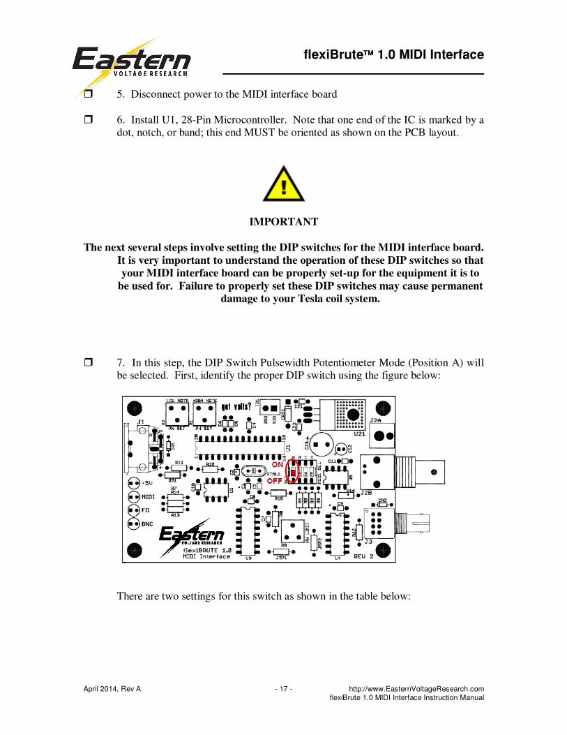
� 5. Disconnect power to the MIDI interface board
� 6. Install U1, 28-Pin Microcontroller. Note that one end of the IC is marked by a
dot, notch, or band; this end MUST be oriented as shown on the PCB layout.
IMPORTANT
The next several steps involve setting the DIP switches for the MIDI interface board.
It is very important to understand the operation of these DIP switches so that
your MIDI interface board can be properly set-up for the equipment it is to
be used for. Failure to properly set these DIP switches may cause permanent
damage to your Tesla coil system.
� 7. In this step, the DIP Switch Pulsewidth Potentiometer Mode (Position A) will
be selected. First, identify the proper DIP switch using the figure below:
There are two settings for this switch as shown in the table below:

flexiBrute 1.0 MIDI Interface
April 2014, Rev A − 18 − http://www.EasternVoltageResearch.com flexiBrute 1.0 MIDI Interface Instruction Manual
Pulsewidth Potentiometer Mode Operation
When this switch is OFF, the pulsewidth of EVERY note
played will be determined by the setting of potentiometer,
R2.
(RECOMMENDED)
When this switch is ON, the pulsewidth of the lowest note
played will be set by adjusting potentiometer, R2, and the pulsewidth of the highest note will be set by adjusting
potentiometer, R1. For notes in between, there will be a
linear mapping between the set pulsewidths of R2 and R1.
For example, if R2 is set for 200us and R1 is set for 100us,
then playing a note in the middle of the range will be
approximately 150us.
Pulsewidth Potentiometer Mode – DIP Switch A set to OFF position

flexiBrute 1.0 MIDI Interface
April 2014, Rev A − 19 − http://www.EasternVoltageResearch.com flexiBrute 1.0 MIDI Interface Instruction Manual
Pulsewidth Potentiometer Mode – DIP Switch A set to ON position
� 8. In this step, the DIP Switch Pulsewidth Range Select (Position B) will be
selected. First, identify the proper DIP switch using the figure below:
flexiBrute 1.0 MIDI Interface
April 2014, Rev A − 20 − http://www.EasternVoltageResearch.com flexiBrute 1.0 MIDI Interface Instruction Manual
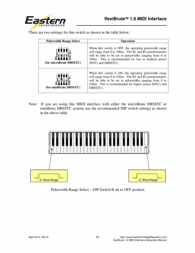
There are two settings for this switch as shown in the table below:
Pulsewidth Range Select Operation
(for microBrute DRSSTC)
When this switch is OFF, the operating pulsewidth range
will range from 0 to 180us. The R1 and R2 potentiometers
will be able to be set to pulsewidths ranging from 0 to
180us. This is recommended for low to medium power
SSTCs and DRSSTCs.
(for miniBrute DRSSTC)
When this switch is ON, the operating pulsewidth range
will range from 0 to 430us. The R1 and R2 potentiometers
will be able to be set to pulsewidths ranging from 0 to
430us. This is recommended for higher power SSTCs and
DRSSTCs.
Note: If you are using this MIDI interface with either the microBrute DRSSTC or
miniBrute DRSSTC system, use the recommended DIP switch settings as shown
in the above table.
Pulsewidth Range Select – DIP Switch B set to OFF position

flexiBrute 1.0 MIDI Interface
April 2014, Rev A − 21 − http://www.EasternVoltageResearch.com flexiBrute 1.0 MIDI Interface Instruction Manual
Pulsewidth Range Select – DIP Switch B set to ON position
� 9. In this step, the DIP Switch MIDI Note Range Select (Position C and D) will
be selected. First, identify the proper DIP switches using the figure below:

flexiBrute 1.0 MIDI Interface
April 2014, Rev A − 22 − http://www.EasternVoltageResearch.com flexiBrute 1.0 MIDI Interface Instruction Manual
There are three settings for this switch as shown in the table below. These two
switches operate as a pair and are used to protect the Tesla coil from notes too
high being played, which could cause damage to the coil due to the large on-times
(high duty cycles) of high pitched notes.
MIDI Note Range Select Operation
RECOMMENDED
HIGHEST PROTECTION
In this mode, MIDI notes above 74 will not be played.
LIMITED PROTECTION
In this mode, MIDI notes above 92 will not be played
NO PROTECTION
In this mode, all MIDI notes up to 127 will be played.
Please note that the lowest note for any range is MIDI note 24.
IMPORTANT
We recommend using HIGHEST PROTECTION for all applications. This includes
using the MIDI interface for both the microBrute and miniBrute DRSSTCs.

flexiBrute 1.0 MIDI Interface
April 2014, Rev A − 23 − http://www.EasternVoltageResearch.com flexiBrute 1.0 MIDI Interface Instruction Manual
MIDI Note Range Select (Playable Notes) – HIGHEST PROTECTION
MIDI Note Range Select (Playable Notes) – LIMITED PROTECTION
MIDI Note Range Select (Playable Notes) – NO PROTECTION
(Note: The keyboard shown only includes notes up to MIDI note 108. In this mode, notes up to MIDI note 127 are also
able to be played)
� 10. At this point, the DIP switch settings should all be set up and you are ready to
begin testing and setting the potentiometer settings for your MIDI interface board.
Connect your MIDI keyboard (or similar) to the MIDI interface as shown in the
figure below. Connect a small 8 ohm speaker, if it is available, as shown as well.
A speaker will be especially helpful in that you will be able to hear the tones
being played while testing and also give you an idea of how the MIDI interface
card operates prior to connecting to an actual SSTC or DRSSTC Tesla coil.

flexiBrute 1.0 MIDI Interface
April 2014, Rev A − 24 − http://www.EasternVoltageResearch.com flexiBrute 1.0 MIDI Interface Instruction Manual
Note: The speaker can be connected directly to either the RCA or BNC connector
or can also be soldered to the terminals / pads on the board for either connector.
Polarity is not important for this connection.
� 11. With everything connected properly, apply power the MIDI interface board.
� 12. Turn the MIDI keyboard ON.
� 13. Check that the MIDI channel on the keyboard is set to channel 1. The MIDI
interface board by default will only read channel 1 from the MIDI instrument.
� 14. Try playing a few notes on the keyboard. If everything is connected and
operating properly, you should begin to hear notes playing through your
connected speaker.
� 15. Verify that the MIDI LED illuminates when notes are played on the
keyboard. Note that the MIDI LED changes state every time a valid MIDI
command is received from the sending instrument. When a single note is played,
the MIDI LED will illuminate, however, if you play a second note, while the first
note is still being held, the MIDI LED will turn off.
� 16. Verify that the FO LED illuminates when notes are played on the keyboard.
This LED indicates that the fiber optic

flexiBrute 1.0 MIDI Interface
April 2014, Rev A − 25 − http://www.EasternVoltageResearch.com flexiBrute 1.0 MIDI Interface Instruction Manual
� 17. Verify that the BNC LED illuminates when notes are played on the keyboard.
This LED indicates that electrical signals are being output at the BNC and RCA
connectors on the MIDI interface board.
� 18. In the next few steps, we will adjust the potentiometers for the operation of
the MIDI interface board. For this step, first disconnect the audio speaker
from the MIDI interface board. Then connect an oscilloscope to the output
BNC of the MIDI interface board or use an oscilloscope probe and look at the
output by monitoring U5 (TC4427), Pin 5. The ground clip of the oscilloscope
can be attached to either the heatsink tab of U21 or one of the mounting holes at
the corners of the board. (Note: If an oscilloscope is not available, you can adjust
the potentiometers using the figures below to get approximate pulsewidth
settings.)
� 19. If you have an oscilloscope, you can verify that the pulsewidth range select is
properly selected and operating correctly. If you do not have an oscilloscope, you
may skip this step.
Pulsewidth Range Select Operation
(for microBrute DRSSTC)
While playing the lowest note on your MIDI keyboard,
adjust R1 and verify that the adjustment range is
approximately from 0-180us.
(for miniBrute DRSSTC)
While playing the lowest note on your MIDI keyboard,
adjust R1 and verify that the adjustment range is approximately from 0-430us.
IMPORTANT – KEY VELOCITY VS. PULSEWIDTH
Please note that the MIDI interface board uses key velocity information from
the received MIDI stream. In otherwords, the hard you press on a key on the
keyboard, the longer the pulsewidth. To ensure maximum pulsewidth is
being measured, be sure to strike each note quickly and firmly as light key
presses will output lower pulsewidths at the output of the MIDI interface
board.

flexiBrute 1.0 MIDI Interface
April 2014, Rev A − 26 − http://www.EasternVoltageResearch.com flexiBrute 1.0 MIDI Interface Instruction Manual
� 20. In this step, you will set the low note maximum pulsewidth. Follow the
instructions as shown in the table below. Please use the table on the next page for
pulsewidth setpoints of R1 and R2 if you do not have an oscilloscope available.
Pulsewidth Potentiometer Mode
Low Note Programming Instructions
NOT RECOMMEND for the
microBrute or miniBrute
DRSSTC
While playing the lowest note on your MIDI keyboard,
adjust potentiometer R2 to the desired maximum
pulsewidth.
For microBrute DRSSTC, the maximum pulsewidth should
not exceed 50us.
For miniBrute DRSSTC, the maximum pulsewidth should
not exceed 100us.
RECOMMENDED
While playing the lowest note on your MIDI keyboard, adjust potentiometer R2 to the desired maximum
pulsewidth.
For microBrute DRSSTC, the recommended maximum
pulsewidth should not exceed 50us.
For miniBrute DRSSTC, the recommended maximum
pulsewidth should not exceed 100us.

flexiBrute 1.0 MIDI Interface
April 2014, Rev A − 27 − http://www.EasternVoltageResearch.com flexiBrute 1.0 MIDI Interface Instruction Manual
Pulsewidth Range Select 0-180us
Approximate Potentiometer Setpoints
(R1, R2)
Pulsewidth Range Select 0-430us
Approximate Potentiometer Setpoints
(R1, R2)
Potentiometer R1, R2 Pulsewidth Setpoints (Approximate)

flexiBrute 1.0 MIDI Interface
April 2014, Rev A − 28 − http://www.EasternVoltageResearch.com flexiBrute 1.0 MIDI Interface Instruction Manual
� 21. In this step, you will set the high note maximum pulsewidth. Follow the
instructions as shown in the table below. Please use the table on the previous
page for pulsewidth setpoints of R1 and R2 if you do not have an oscilloscope
available.
Pulsewidth Potentiometer Mode High Note Programming Instructions
Not applicable. The maximum high note pulsewidth for
DIP switch setting is equal to the maximum low note
pulsewidth as set in step 19.
RECOMMENDED
While playing the lowest note on your MIDI keyboard,
adjust potentiometer R1 to the desired maximum pulsewidth.
For microBrute DRSSTC, the recommended maximum
pulsewidth should not exceed 25us.
For miniBrute DRSSTC, your recommended maximum
pulsewidth should not exceed 50us.

flexiBrute 1.0 MIDI Interface
April 2014, Rev A − 29 − http://www.EasternVoltageResearch.com flexiBrute 1.0 MIDI Interface Instruction Manual
� 22. Verify that the keyboard plays the notes as shown in the table below given
the present DIP switch selection for the Note Range Select. Note that if you have
a smaller keyboard, you may not be able to play notes that fall within the cut-off
range of the Note Range Select.
MIDI Note Range Select Operation
RECOMMENDED
Verify that the notes being played cut-off as shown in the
figure below:
Verify that the notes being played cut-off as shown in the
figure below:
Verify that all notes are able to be played on your MIDI
keyboard.
IMPORTANT – KEYBOARD SIZE
Please note that if you have a smaller keyboard, you will not be able to test or
play all the notes shown in the table above.

flexiBrute 1.0 MIDI Interface
April 2014, Rev A − 30 − http://www.EasternVoltageResearch.com flexiBrute 1.0 MIDI Interface Instruction Manual
At this point, your MIDI interface card is properly set-up and configured. You are now
ready to connect the MIDI interface card to your Tesla coil!
Operation with a Tesla Coil
Okay, so lets make some music!
flexiBrute 1.0 MIDI Interface
April 2014, Rev A − 31 − http://www.EasternVoltageResearch.com flexiBrute 1.0 MIDI Interface Instruction Manual
IMPORTANT NOTE – REV 2 BOARDS
REV 2 boards are identified by the “REV 2” silkscreen
text in the lower rightside of the board.
The RCA connector J2A is backwards on the board.
Therefore, the GND and POSITIVE connections are
effectively backwards. There are two ways to correct
this issue with the REV 2 board:
1. Simply install the RCA connector, J2A, on the underside of the board, but have
the connector facing inwards as opposed to outwards. This could be on the topside
of the board, but the connector barrel would interfere with other components on the
topside.
2. Install the RCA connector, J2A, as normal but modify the RCA cable so that the
conductors reverse from one end to the other. Although this way modifies the cable,
it still allows the RCA connector to be installed normally on the topside of the board
facing outwards as shown in the photo on the first page of this manual.

flexiBrute 1.0 MIDI Interface
April 2014, Rev A − 32 − http://www.EasternVoltageResearch.com flexiBrute 1.0 MIDI Interface Instruction Manual
Before connecting the flexiBrute 1.0 MIDI Interface to any SSTC or DRSSTC Tesla
Coil, be sure that you are completely familiar with the operation of the MIDI
Interface as well as verified the operation of the interface card using an oscilloscope
or similar device. It is important to ensure that the MIDI Interface pulsewidth
ranges are programmed per the SSTC or DRSSTC it is being used for and that the
proper settings are programmed before connecting to an SSTC or DRSSTC.
WARNING
Unplugging the MIDI connector while playing a note will result in this note being
played indefinitely through the MIDI Interface Card. This is simply how the
MIDI protocol operates, since the note will not stop until a stop-note
command is sent by the MIDI device.
Modulator Output Specifications
Please use the following table to determine the proper interface between the MIDI
interface board and your DRSSTC or SSTC system.
Output Connector Specification
J2A, RCA
RCA connector (female)
TTL 5V logic compatible
0V = OFF
5V = ON
J2B, BNC
BNC connector (female) TTL 5V logic compatible
0V = OFF
5V = ON
J3, Fiber Optic
HFBR1412T Transmitter (ST connector)
Compatible with HFBR 2412T Receiver (ST connector)
Light OFF = OFF
Light ON = ON

flexiBrute 1.0 MIDI Interface
April 2014, Rev A − 33 − http://www.EasternVoltageResearch.com flexiBrute 1.0 MIDI Interface Instruction Manual
MIDI Channel
The MIDI interface board only reads MIDI commands issued on Channel 1 of the MIDI
datastream. Please ensure your instrument is set to Channel 1 before use.
MIDI Board LED Status
The follow table lists the MIDI interface board status LEDs and their functions.
Status LED Function
+5V
This LED will illuminate when there is input power and the
5V logic power is present.
MIDI
This LED will illuminate whenever a valid MIDI command
is received by the MIDI interface board. Sample valid
commands would be MIDI note ON, and MIDI note OFF.
Note that this LED will toggle ON/OFF (change state) on
each valid MIDI command received. So for example, if you
press a key, the MIDI LED will illuminate. If you continue holding that key and press a second key, the MIDI LED will
turn off.
FO
This LED illuminates when an output modulator pulse is
active on the fiber optic connector. Note that the brightness
of this LED will vary depending on the magnitude of the
pulsewidth and duty cycle at the output.
BNC
This LED illuminates when an output modulator pulse is
active on either the RCA or BNC output connectors. Note
that the brightness of this LED will vary depending on the magnitude of the pulsewidth and duty cycle at the output.

flexiBrute 1.0 MIDI Interface
April 2014, Rev A − 34 − http://www.EasternVoltageResearch.com flexiBrute 1.0 MIDI Interface Instruction Manual
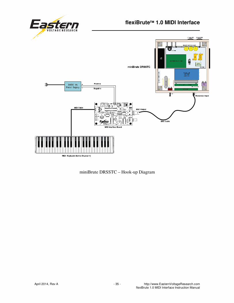
Connecting the MIDI Interface Board to a DRSSTC / SSTC
The follow figures show sample hook-up diagrams for the MIDI interface board.
Positive+
Negative-
9VDC, 1A
Power Supply
MIDI Cable
RCA Cable
Modulator Input
RCAOutput
MIDI Interface Board
microBrute DRSSTC Board
MIDI Keyboard (Set to Channel 1)
microBrute DRSSTC – Hook-up Diagram
flexiBrute 1.0 MIDI Interface
April 2014, Rev A − 35 − http://www.EasternVoltageResearch.com flexiBrute 1.0 MIDI Interface Instruction Manual
miniBrute DRSSTC – Hook-up Diagram

flexiBrute 1.0 MIDI Interface
April 2014, Rev A − 36 − http://www.EasternVoltageResearch.com flexiBrute 1.0 MIDI Interface Instruction Manual
Typical DRSSTC or SSTC – Hook-up Diagram

flexiBrute 1.0 MIDI Interface
April 2014, Rev A − 37 − http://www.EasternVoltageResearch.com flexiBrute 1.0 MIDI Interface Instruction Manual
Troubleshooting
PROBLEM: There is no output on the MIDI interface board and the MIDI interface LED
does not illuminate.
SOLUTION: Verify that the instrument is set to MIDI channel 1.
Conclusion
We sincerely hope that you have enjoyed the construction of this Eastern Voltage
Research Kit. As always, we have tried to write this instruction manual in the easiest,
most “user friendly” format that is possible. As our customers, we value your opinions,
comments, and additions that you would like to see in future publications. Please submit
comments or ideas to:
Eastern Voltage Research, LLC
Technical Support
Thanks again from the people here at Eastern Voltage Research.
Terms and Conditions of Sale
Before opening or assemblying your kit, please read and review the latest Terms and
Conditions of Sale on our website at the following link:
http://www.easternvoltageresearch.com/terms.html