Fiber optics
18
Table of Contents 1.0 Fiber Optics Network ………………………………………..……………………………………………….3 2.0 History…………………………………………………………………………………………………………………4 3.0 Fiber Optics What is it ?……………………………………………….…………………………………….5 4.0 Fiber Optic Introduction ……………………………..…………….………………………………………6 5.0 Transmission of Light through Fiber………………………………………….………….………….….8 6.0 Fiber Optic Network………………………………….……………….………………………………………10 7.0 Fiber Cable…………………………………………………………………….………………………………….12 8.0 Types of Cables…………………………………………………………….…….……………….…………….13 8.1 GLASS FIBER…………………………………………………………………………………………...13 8.2 PLASTIC FIBER…………………………………………………………………………………………13 8.3 Plastic Clad-Silica (PCS)……………………………………………………………………………13 9.0 Fiber Optics Modes………………………………………………………………….………………………..14 9.1 Singlemode Fiber…………………………………………………………….………………………14 9.2 Multimode Step-Index Fiber…………………………………………….……………………..14 10.0 Fiber Optic Communications………………………………………………………….………………….15 10.0 Advantages of Fiber Optic …………………..…………………………………………………………….16 10.1 Optical Fibre Over Copper Cables………………………………………….………………..16 11.0 Fiber Optic Specifications…………………………………………………………………………..………16 12.0 Refrances………………………………………………………………………………………………………….17 13.0 Conclusion……………………………………………………………………………………..………………….18
-
Upload
the-university-of-lahore -
Category
Engineering
-
view
201 -
download
2
Transcript of Fiber optics

Table of Contents
1.0 Fiber Optics Network ………………………………………..……………………………………………….3
2.0 History…………………………………………………………………………………………………………………4
3.0 Fiber Optics What is it ?……………………………………………….…………………………………….5
4.0 Fiber Optic Introduction ……………………………..…………….………………………………………6
5.0 Transmission of Light through Fiber………………………………………….………….………….….8
6.0 Fiber Optic Network………………………………….……………….………………………………………10
7.0 Fiber Cable…………………………………………………………………….………………………………….12 8.0 Types of Cables…………………………………………………………….…….……………….…………….13
8.1 GLASS FIBER…………………………………………………………………………………………...13
8.2 PLASTIC FIBER…………………………………………………………………………………………13
8.3 Plastic Clad-Silica (PCS)……………………………………………………………………………13
9.0 Fiber Optics Modes………………………………………………………………….………………………..14
9.1 Singlemode Fiber…………………………………………………………….………………………14
9.2 Multimode Step-Index Fiber…………………………………………….……………………..14
10.0 Fiber Optic Communications………………………………………………………….………………….15
10.0 Advantages of Fiber Optic …………………..…………………………………………………………….16
10.1 Optical Fibre Over Copper Cables………………………………………….………………..16
11.0 Fiber Optic Specifications…………………………………………………………………………..………16
12.0 Refrances………………………………………………………………………………………………………….17
13.0 Conclusion……………………………………………………………………………………..………………….18

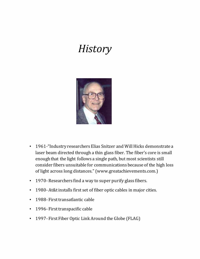
History
• 1961-“Industry researchers Elias Snitzer and Will Hicks demonstrate a
laser beam directed through a thin glass fiber. The fiber’s core is small
enough that the light follows a single path, but most scientists still
consider fibers unsuitable for communications because of the high loss
of light across long distances.” (www.greatachievements.com.)
• 1970- Researchers find a way to super purify glass fibers.
• 1980- At&t installs first set of fiber optic cables in major cities.
• 1988- First transatlantic cable
• 1996- First transpacific cable
• 1997- First Fiber Optic Link Around the Globe (FLAG)

Fiber Optics What Is It?
Fiber Optics are cables that are made of optical fibers that can transmit large
amounts of information at the speed of light.
• Transmitting communications signals over hair thin strands of
glass or plastic
• Not a "new" technology
• Concept a century old
• Used commercially for last 25 years

FIBER OPTICS Many people in the computer industry take enormous pride in how fast
computer technology is improving. The original (1981) IBM PC ran at a clock speed of 4.77 MHz. Twenty years later, PCs could run at 2 GHz, a gain of a factor of 20 per decade. Not too bad.
In the same period, wide area data communication went from 56 kbps (the ARPANET) to 1 Gbps (modern optical communication), a gain of more than a factor of 125 per decade, while at the same time the error rate went from 10-5 per bit to almost zero.
Furthermore, single CPUs are beginning to approach physical limits, such as speed of light and heat dissipation problems. In contrast, with current fiber technology, the achievable bandwidth is certainly in excess of 50,000 Gbps (50 Tbps) and many people are looking very hard for better technologies and materials. The current practical signaling limit of about 10 Gbps is due to our inability to convert between electrical and optical signals any faster, although in the laboratory, 100 Gbps has been achieved on a single fiber.
In the race between computing and communication, communication won. The full implications of essentially infinite bandwidth (although not at zero cost) have not yet sunk in to a generation of computer scientists and engineers taught to think in terms of the low Nyquist and Shannon limits imposed by copper wire. The new conventional wisdom should be that all computers are hopelessly slow and that networks should try to avoid computation at all costs, no matter how much

bandwidth that wastes. In this section we will study fiber optics to see how that transmission technology works.
An optical transmission system has three key components: the light source, the transmission medium, and the detector. Conventionally, a pulse of light indicates a 1 bit and the absence of light indicates a 0 bit. The transmission medium is an ultra-thin fiber of glass. The detector generates an electrical pulse when light falls on it. By attaching a light source to one end of an optical fiber and a detector to the other, we have a unidirectional data transmission system that accepts an electrical signal, converts and transmits it by light pulses, and then reconverts the output to an electrical signal at the receiving end.
This transmission system would leak light and be useless in practice except for an interesting principle of physics. When a light ray passes from one medium to another, for example, from fused silica to air, the ray is refracted (bent) at the silica/air boundary. Here we see a light ray incident on the boundary at an angle a1 emerging at an angle b1. The amount of refraction depends on the properties of the two media (in particular, their indices of refraction). For angles of incidence above a certain critical value, the light is refracted back into the silica; none of it escapes into the air. Thus, a light ray incident at or above the critical angle is trapped inside the fiber, and can propagate for many kilometers with virtually no loss
The sketch shows only one trapped ray, but since any light ray incident on the boundary above the critical angle will be reflected internally,

many different rays will be bouncing around at different angles. Each ray is said to have a different mode, so a fiber having this property is called a multimode fiber.
However, if the fiber's diameter is reduced to a few wavelengths of light, the fiber acts like a wave guide, and the light can propagate only in a straight line, without bouncing, yielding a single-mode fiber. Single-mode fibers are more expensive but are widely used for longer distances. Currently available single-mode fibers can transmit data at 50 Gbps for 100 km without amplification. Even higher data rates have been achieved in the laboratory for shorter distances.
Transmission of Light through Fiber
Optical fibers are made of glass, which, in turn, is made from sand, an inexpensive raw material available in unlimited amounts. Glassmaking was known to the ancient Egyptians, but their glass had to be no more than 1 mm thick or the light could not shine through. Glass transparent enough to be useful for windows was developed during the Renaissance. The glass used for modern optical fibers is so transparent that if the oceans were full of it instead of water, the seabed would be as visible from the surface as the ground is from an airplane on a clear day.
The attenuation of light through glass depends on the wavelength of the light (as well as on some physical properties of the glass). For the
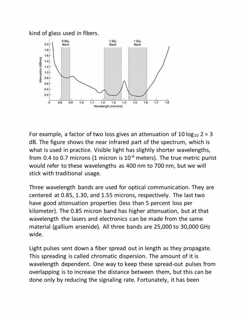
kind of glass used in fibers.
For example, a factor of two loss gives an attenuation of 10 log10 2 = 3 dB. The figure shows the near infrared part of the spectrum, which is what is used in practice. Visible light has slightly shorter wavelengths, from 0.4 to 0.7 microns (1 micron is 10-6 meters). The true metric purist would refer to these wavelengths as 400 nm to 700 nm, but we will stick with traditional usage.
Three wavelength bands are used for optical communication. They are centered at 0.85, 1.30, and 1.55 microns, respectively. The last two have good attenuation properties (less than 5 percent loss per kilometer). The 0.85 micron band has higher attenuation, but at that wavelength the lasers and electronics can be made from the same material (gallium arsenide). All three bands are 25,000 to 30,000 GHz wide.
Light pulses sent down a fiber spread out in length as they propagate. This spreading is called chromatic dispersion. The amount of it is wavelength dependent. One way to keep these spread-out pulses from overlapping is to increase the distance between them, but this can be done only by reducing the signaling rate. Fortunately, it has been
discovered that by making the pulses in a special shape related to the reciprocal of the hyperbolic cosine, nearly all the dispersion effects cancel out, and it is possible to send pulses for thousands of kilometers without appreciable shape distortion. These pulses are called solitons. A considerable amount of research is going on to take solitons out of the lab and into the field.
Fiber Optic Networks
Fiber optics can be used for LANs as well as for long-haul transmission,
although tapping into it is more complex than connecting to an Ethernet. One way around the problem is to realize that a ring network is really just a collection of point-to-point links. The interface at each computer passes the light pulse stream through to the next link and also serves as a T junction to allow the computer to send and accept messages.
Two types of interfaces are used. A passive interface consists of two taps fused onto the main fiber. One tap has an LED or laser diode at the end of it (for transmitting), and the other has a photodiode (for receiving). The tap itself is completely passive and is thus extremely reliable because a broken LED or photodiode does not break the ring. It just takes one computer off-line.
The other interface type, is the active repeater. The incoming light is converted to an electrical signal, regenerated to full strength if it has been weakened, and retransmitted as light. The interface with the computer is an ordinary copper wire that comes into the signal regenerator. Purely optical repeaters are now being used, too. These devices do not require the optical to electrical to optical conversions, which means they can operate at extremely high bandwidths.

If an active repeater fails, the ring is broken and the network goes down. On the other hand, since the signal is regenerated at each interface, the individual computer-to-computer links can be kilometers long, with virtually no limit on the total size of the ring. The passive interfaces lose light at each junction, so the number of computers and total ring length are greatly restricted.
A ring topology is not the only way to build a LAN using fiber optics. It is also possible to have hardware broadcasting by using the passive star construction.. In this design, each interface has a fiber running from its transmitter to a silica cylinder, with the incoming fibers fused to one end of the cylinder. Similarly, fibers fused to the other end of the cylinder are run to each of the receivers. Whenever an interface emits a light pulse, it is diffused inside the passive star to illuminate all the receivers, thus achieving broadcast. In effect, the passive star combines all the incoming signals and transmits the merged result on all lines. Since the incoming energy is divided among all the outgoing lines, the number of nodes in the network is limited by the sensitivity of the photodiodes.
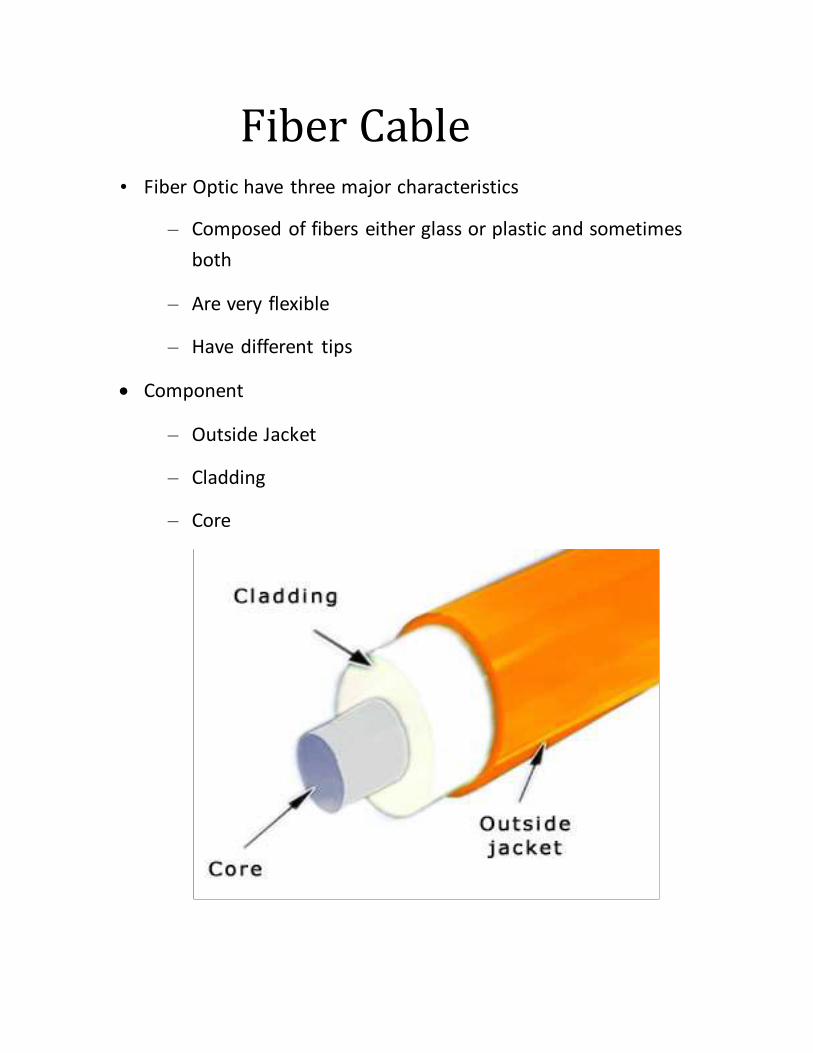
Fiber Cable
• Fiber Optic have three major characteristics
– Composed of fibers either glass or plastic and sometimes
both
– Are very flexible
– Have different tips
Component
– Outside Jacket
– Cladding
– Core
Types of Cables
Glass Fibers
o Glass Core
o Glass Cladding
o Ultra Pure Ultra Transparent Glass
o Made Of Silicon Dioxide
o Low Attenuation
o Popular among industries
Plastic Fibers
o Core Generally Consists Of Polymethyl Methacrylate (Acrylic
Glass) (PMMA) Coated With A Fluoropolymer
o High Attenuation
o Used Mostly In Automotives
o Affordable
o Very Durable
Plastic Clad-Silica (PCS)
o Glass Fiber Core sometimes silicone
o Cladding is Plastic or silicone
o Silicone covering and insulators
o Not common
o Has Defects
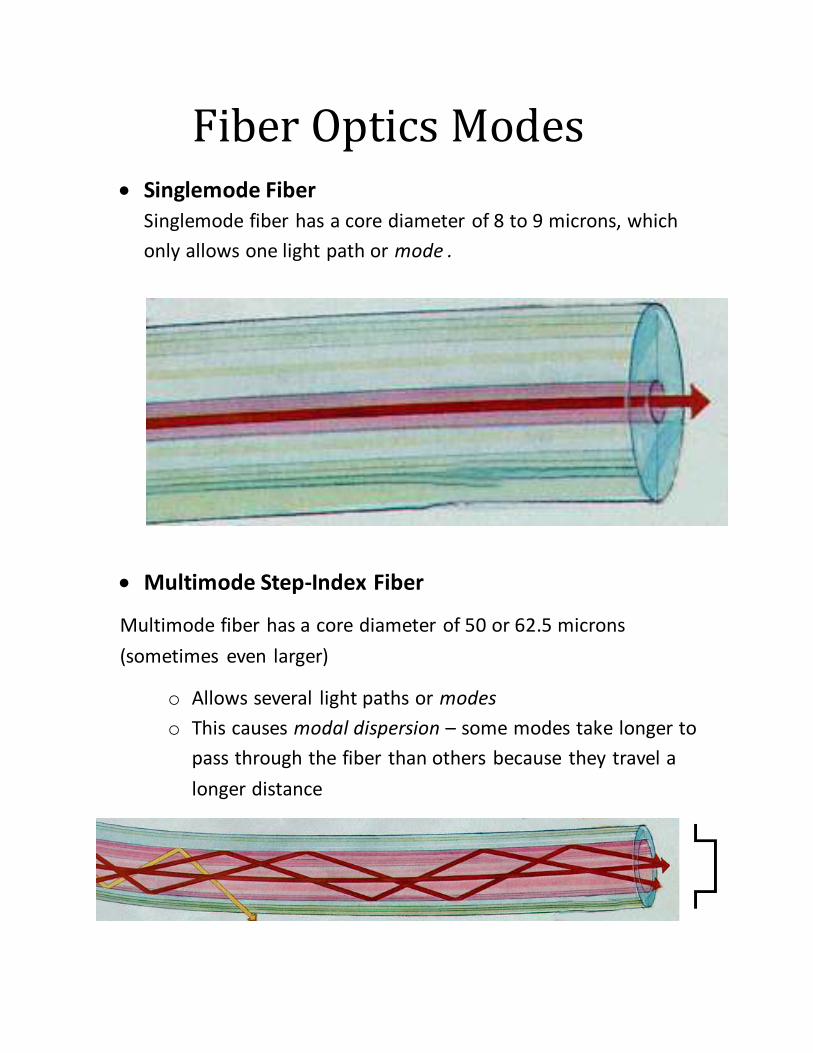
Fiber Optics Modes Singlemode Fiber
Singlemode fiber has a core diameter of 8 to 9 microns, which
only allows one light path or mode .
Multimode Step-Index Fiber
Multimode fiber has a core diameter of 50 or 62.5 microns
(sometimes even larger)
o Allows several light paths or modes
o This causes modal dispersion – some modes take longer to
pass through the fiber than others because they travel a
longer distance
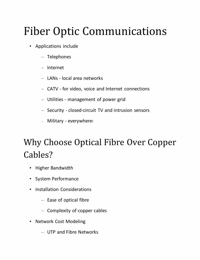
Fiber Optic Communications • Applications include
– Telephones
– Internet
– LANs - local area networks
– CATV - for video, voice and Internet connections
– Utilities - management of power grid
– Security - closed-circuit TV and intrusion sensors
– Military - everywhere!
Why Choose Optical Fibre Over Copper
Cables?
• Higher Bandwidth
• System Performance
• Installation Considerations
– Ease of optical fibre
– Complexity of copper cables
• Network Cost Modeling
– UTP and Fibre Networks
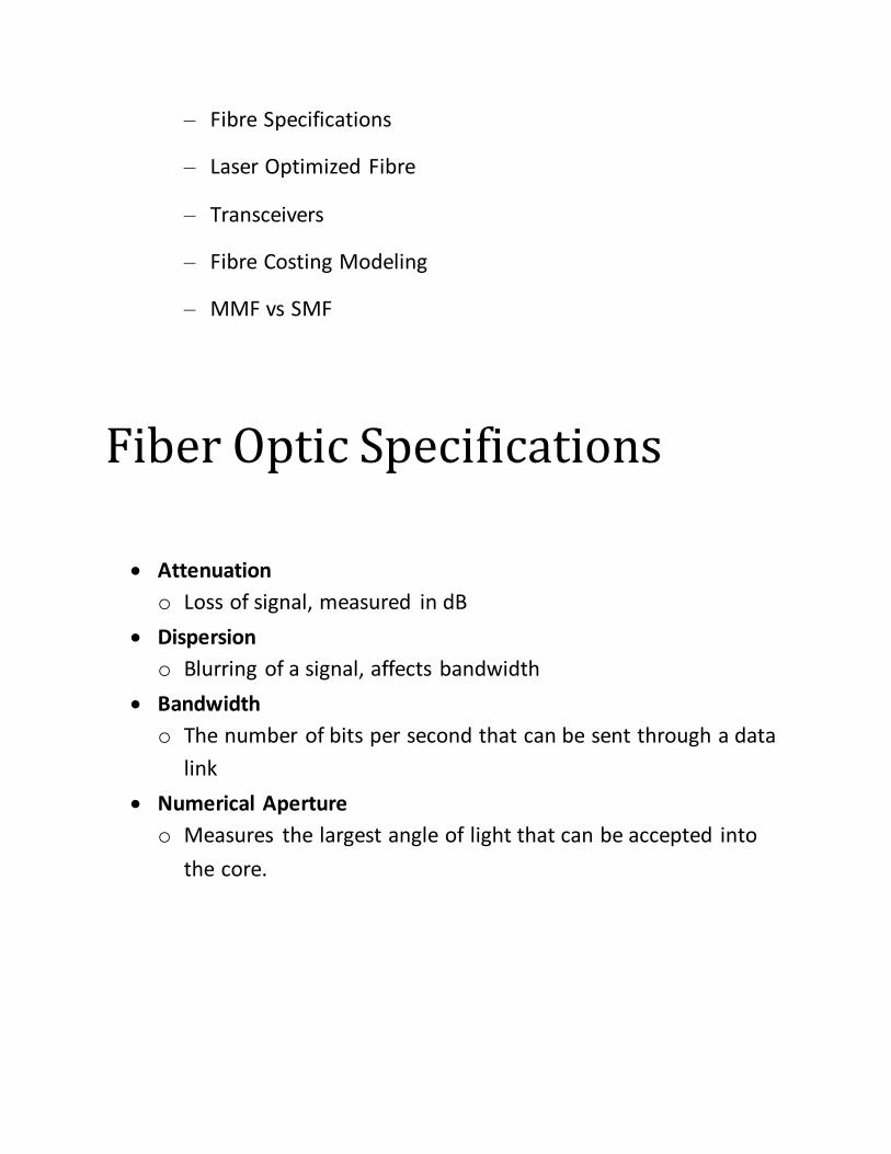
– Fibre Specifications
– Laser Optimized Fibre
– Transceivers
– Fibre Costing Modeling
– MMF vs SMF
Fiber Optic Specifications
Attenuation
o Loss of signal, measured in dB
Dispersion
o Blurring of a signal, affects bandwidth
Bandwidth
o The number of bits per second that can be sent through a data
link
Numerical Aperture
o Measures the largest angle of light that can be accepted into
the core.

References
1. www.thefoa.org/PPT/HSintro
2. www.thefoa.org/PPT/hsintro/HSintro.htm
3. www.uweb.ucsb.edu/~leonard/leodavidpwrpnt
4. www.vdvworks.com/vdvacademy
5. www.ncs.gov
6. samsclass.info/211/ppt/ch2.ppt
7. www.authorstream.com/.../aSGuest283-91536-fibre-optics-introduction-3-cable-
fiber-entertainment-ppt-powerpoint
8. n1.slideserve.com/PPTFiles/FIBER_52917_58236.ppt
9. ccg.ee.ntust.edu.tw/project/Chap1%20fiber%20optics.pdf
10. www.fig.net/nottingham/proc/ts_06_1_brunner.pdf -

Conclusion
This concludes our study of Fiber Optics. We have looked at how
they work and how they are made. We have examined the
properties of fibers, and how fibers are joined together. Although
this presentation does not cover all the aspects of optical fiber
work it will have equipped you knowledge and skills essential to
the fiber optic industry.
TERM PAPER _____________________________________________________________________________________
FIBER OPTICS
Submitted To:
SIR WASEEM IQBAL
Submitted By:
UMAR IKRAM (MIT01103015)
WASEEM ISHAQ (MIT01103015)
Dec 31, 2011