Feasibility analysis of DML with 7nm Pass bandgrouper.ieee.org/groups/802/3/ca/public/meeting... ·...
20
Accelink Technologies Co., Ltd. Lighting Your Dreams | 让光引领梦想 Feasibility analysis of DML with 7nm Pass band 2017, May Page 1
Transcript of Feasibility analysis of DML with 7nm Pass bandgrouper.ieee.org/groups/802/3/ca/public/meeting... ·...
Accelink Technologies Co., Ltd.
Lighting Your Dreams | 让光引领梦想
Feasibility analysis of DML with 7nm Pass band 2017, May
Page 1
Accelink Technologies Co., Ltd.
Lighting Your Dreams | 让光引领梦想
Contributors
Xuguang Chen, Qiangpeng Hu, Jie Zhao, Jun Zhang, Wanhui He, Yi
Jiang, Qijin Duan - Accelink
Dekun Liu - Huawei
Dezhi Zhang – China Telecom
Page 2
Accelink Technologies Co., Ltd.
Lighting Your Dreams | 让光引领梦想
Background
Last meeting Mr. Zhang from CTC presented the idea 7nm Pass band
for US0 instead of 3nm (Plan A) in his contribution Multi-rate receiver
Survey and analysis (Zhangdezhi_3ca_1_0317). Due to DMLs can be
used in ONUs for low cost purpose, further investigation need to be
analyzed.
This presentation demonstrates one of implementation approaches
without the TEC and some potential application scenarios based on the
DML with 7nm Pass band.
Page 3
Accelink Technologies Co., Ltd.
Lighting Your Dreams | 让光引领梦想
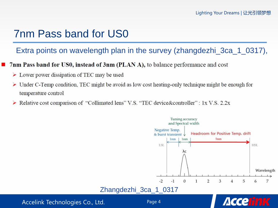
7nm Pass band for US0
Extra points on wavelength plan in the survey (zhangdezhi_3ca_1_0317),
Zhangdezhi_3ca_1_0317
Page 4

Accelink Technologies Co., Ltd.
Lighting Your Dreams | 让光引领梦想
One of heating-only implementation approaches
Pros
• A Thin-film strip resistor is more cheaper than a TEC
• Actuator for heating resistor is simpler than TEC controller
• Compact and easy to be integrated
Cons
• Wavelength control is unavailable
for higher ambient temperature
• Additional heating resistor may
impact layouts
Thin-film resistor
Heat sink Thermistor
Laser
7nm PB DML without any TEC
Page 5
Accelink Technologies Co., Ltd.
Lighting Your Dreams | 让光引领梦想
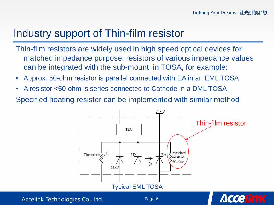
Industry support of Thin-film resistor
Thin-film resistors are widely used in high speed optical devices for
matched impedance purpose, resistors of various impedance values
can be integrated with the sub-mount in TOSA, for example:
• Approx. 50-ohm resistor is parallel connected with EA in an EML TOSA
• A resistor <50-ohm is series connected to Cathode in a DML TOSA
Specified heating resistor can be implemented with similar method
Page 6
Typical EML TOSA
Thin-film resistor
Accelink Technologies Co., Ltd.
Lighting Your Dreams | 让光引领梦想
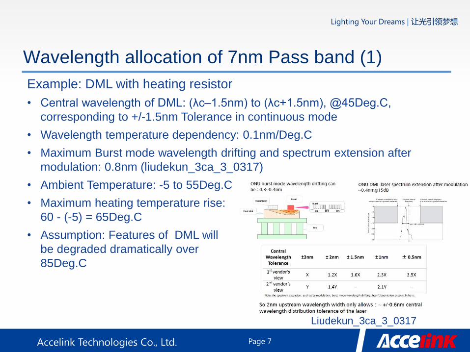
Wavelength allocation of 7nm Pass band (1)
Example: DML with heating resistor
• Central wavelength of DML: (λc–1.5nm) to (λc+1.5nm), @45Deg.C,
corresponding to +/-1.5nm Tolerance in continuous mode
• Wavelength temperature dependency: 0.1nm/Deg.C
• Maximum Burst mode wavelength drifting and spectrum extension after
modulation: 0.8nm (liudekun_3ca_3_0317)
• Ambient Temperature: -5 to 55Deg.C
• Maximum heating temperature rise:
60 - (-5) = 65Deg.C
• Assumption: Features of DML will
be degraded dramatically over
85Deg.C
Liudekun_3ca_3_0317
Page 7

Accelink Technologies Co., Ltd.
Lighting Your Dreams | 让光引领梦想
Wavelength allocation of 7nm Pass band (2)
Spectral Width
& Tuning
accuracy=1nm -0.5nm
-1.5nm
+1.5nm
+0.5nm
+3.5nm
+2.5nm
+5.5nm
+4.5nm
Headroom for
Wavelength
drift=3.5nm
λc-1.5nm
@45Deg.C
Nominal λc
@45Deg.C
Headroom for positive
temperature drift
Tmax: 80Deg.C
0nm λc
@60Deg.C
Heating up
λc+1.5nm
@45Deg.C
Positive
tolerance
=1.5nm
Burst mode
drifting & Mod
extension=1nm
>80Deg.C
>80Deg.C
>80Deg.C
Page 8

Accelink Technologies Co., Ltd.
Lighting Your Dreams | 让光引领梦想
Comparison: Heating resistor and TEC
DML with heating resistor
• Operation temperature range will shrink to high temperature zone
Comparison TEC Heating resistor Uncooled
Operating Temperature
range (Deg.C)
Set-point, i.e.
~ 45 45 to 80 * Total
Key component/Technology Peltier/Semiconductor Resistor/Passive -
Temperature sensor Y Y N
Controller
Control MCU &
Complex controller
MCU &
Simple controller -
Current polarity Bipolar Unipolar -
Pin-outs TEC+, TEC-, Rth Vout, Rth -
Note *: Temperature ranges are variable for different tolerance Central wavelength at 45Deg.C.
For Central wavelength=(λc+1.5nm) at 45Deg.C, operating temperature range may be typ.
45~80Deg.C or 30~80Deg.C for power saving purpose. For Central wavelength=(λc-1.5nm) at
45Deg.C, operating temperature range may be 60~80Deg.C
Page 9
Accelink Technologies Co., Ltd.
Lighting Your Dreams | 让光引领梦想
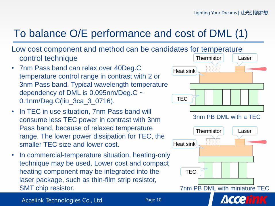
To balance O/E performance and cost of DML (1)
Low cost component and method can be candidates for temperature
control technique
• 7nm Pass band can relax over 40Deg.C
temperature control range in contrast with 2 or
3nm Pass band. Typical wavelength temperature
dependency of DML is 0.095nm/Deg.C ~
0.1nm/Deg.C(liu_3ca_3_0716).
• In TEC in use situation, 7nm Pass band will
consume less TEC power in contrast with 3nm
Pass band, because of relaxed temperature
range. The lower power dissipation for TEC, the
smaller TEC size and lower cost.
• In commercial-temperature situation, heating-only
technique may be used. Lower cost and compact
heating component may be integrated into the
laser package, such as thin-film strip resistor,
SMT chip resistor. 7nm PB DML with miniature TEC
3nm PB DML with a TEC
Heat sink
Thermistor Laser
TEC
Thermistor Laser
TEC
Heat sink
Page 10
Accelink Technologies Co., Ltd.
Lighting Your Dreams | 让光引领梦想
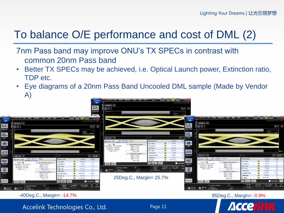
To balance O/E performance and cost of DML (2)
7nm Pass band may improve ONU’s TX SPECs in contrast with
common 20nm Pass band • Better TX SPECs may be achieved, i.e. Optical Launch power, Extinction ratio,
TDP etc.
• Eye diagrams of a 20nm Pass Band Uncooled DML sample (Made by Vendor
A)
25Deg.C., Margin= 25.7%
Page 11
-40Deg.C., Margin= -14.7% 85Deg.C., Margin= -0.9%

Accelink Technologies Co., Ltd.
Lighting Your Dreams | 让光引领梦想
To balance O/E performance and cost of DML (3)
When link budget of US0 is insufficient, 3nm Pass band may be better
choice
Zhang_3ca_1_1116
Page 12
Accelink Technologies Co., Ltd.
Lighting Your Dreams | 让光引领梦想
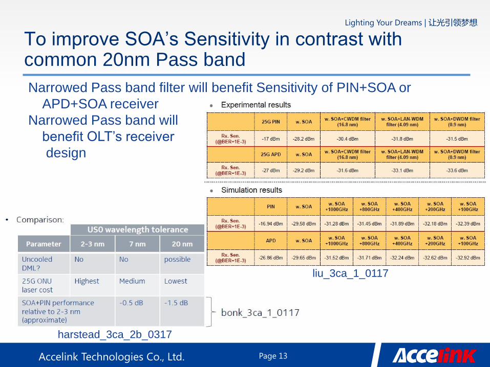
To improve SOA’s Sensitivity in contrast with common 20nm Pass band
Narrowed Pass band filter will benefit Sensitivity of PIN+SOA or
APD+SOA receiver
Narrowed Pass band will
benefit OLT’s receiver
design
harstead_3ca_2b_0317
liu_3ca_1_0117
Page 13
Accelink Technologies Co., Ltd.
Lighting Your Dreams | 让光引领梦想
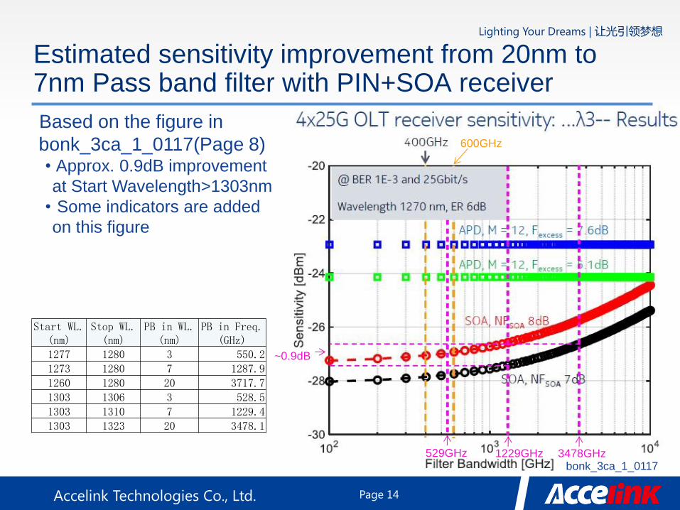
Estimated sensitivity improvement from 20nm to 7nm Pass band filter with PIN+SOA receiver
Based on the figure in
bonk_3ca_1_0117(Page 8) • Approx. 0.9dB improvement
at Start Wavelength>1303nm
• Some indicators are added
on this figure
Page 14
600GHz
529GHz 1229GHz bonk_3ca_1_0117
Start WL. (nm)
Stop WL. (nm)
PB in WL. (nm)
PB in Freq. (GHz)
1277 1280 3 550.2
1273 1280 7 1287.9
1260 1280 20 3717.7
1303 1306 3 528.5
1303 1310 7 1229.4
1303 1323 20 3478.1
~0.9dB
3478GHz
Accelink Technologies Co., Ltd.
Lighting Your Dreams | 让光引领梦想
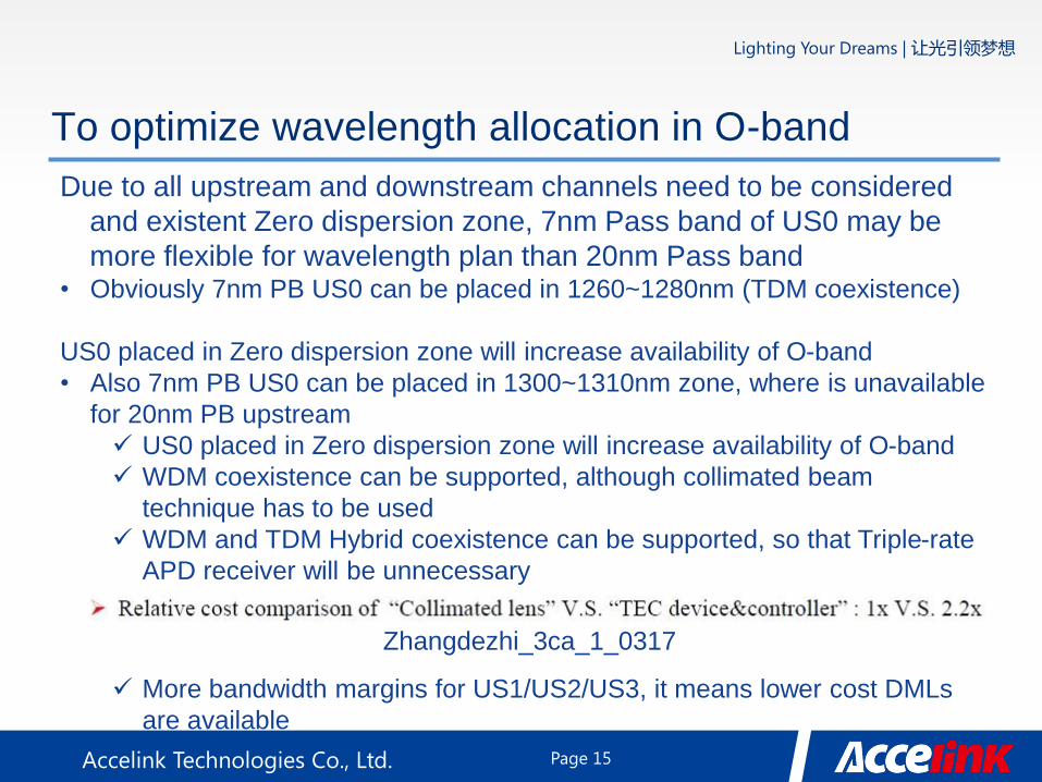
To optimize wavelength allocation in O-band
Due to all upstream and downstream channels need to be considered
and existent Zero dispersion zone, 7nm Pass band of US0 may be
more flexible for wavelength plan than 20nm Pass band • Obviously 7nm PB US0 can be placed in 1260~1280nm (TDM coexistence)
US0 placed in Zero dispersion zone will increase availability of O-band
• Also 7nm PB US0 can be placed in 1300~1310nm zone, where is unavailable
for 20nm PB upstream
US0 placed in Zero dispersion zone will increase availability of O-band
WDM coexistence can be supported, although collimated beam
technique has to be used
WDM and TDM Hybrid coexistence can be supported, so that Triple-rate
APD receiver will be unnecessary
More bandwidth margins for US1/US2/US3, it means lower cost DMLs
are available
Zhangdezhi_3ca_1_0317
Page 15
Accelink Technologies Co., Ltd.
Lighting Your Dreams | 让光引领梦想
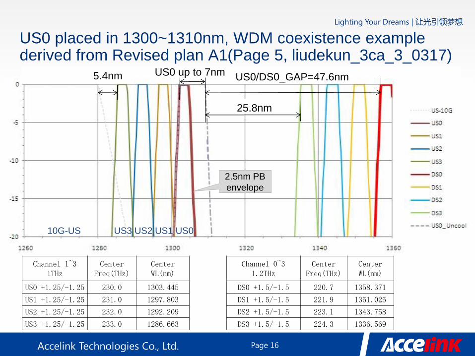
US0 placed in 1300~1310nm, WDM coexistence example derived from Revised plan A1(Page 5, liudekun_3ca_3_0317)
Channel 1~3 1THz
Center Freq(THz)
Center WL(nm)
US0 +1.25/-1.25 230.0 1303.445
US1 +1.25/-1.25 231.0 1297.803
US2 +1.25/-1.25 232.0 1292.209
US3 +1.25/-1.25 233.0 1286.663
Channel 0~3 1.2THz
Center Freq(THz)
Center WL(nm)
DS0 +1.5/-1.5 220.7 1358.371
DS1 +1.5/-1.5 221.9 1351.025
DS2 +1.5/-1.5 223.1 1343.758
DS3 +1.5/-1.5 224.3 1336.569
10G-US US3 US2 US1 US0
US0/DS0_GAP=47.6nm US0 up to 7nm
25.8nm
5.4nm
2.5nm PB
envelope
Page 16
Accelink Technologies Co., Ltd.
Lighting Your Dreams | 让光引领梦想
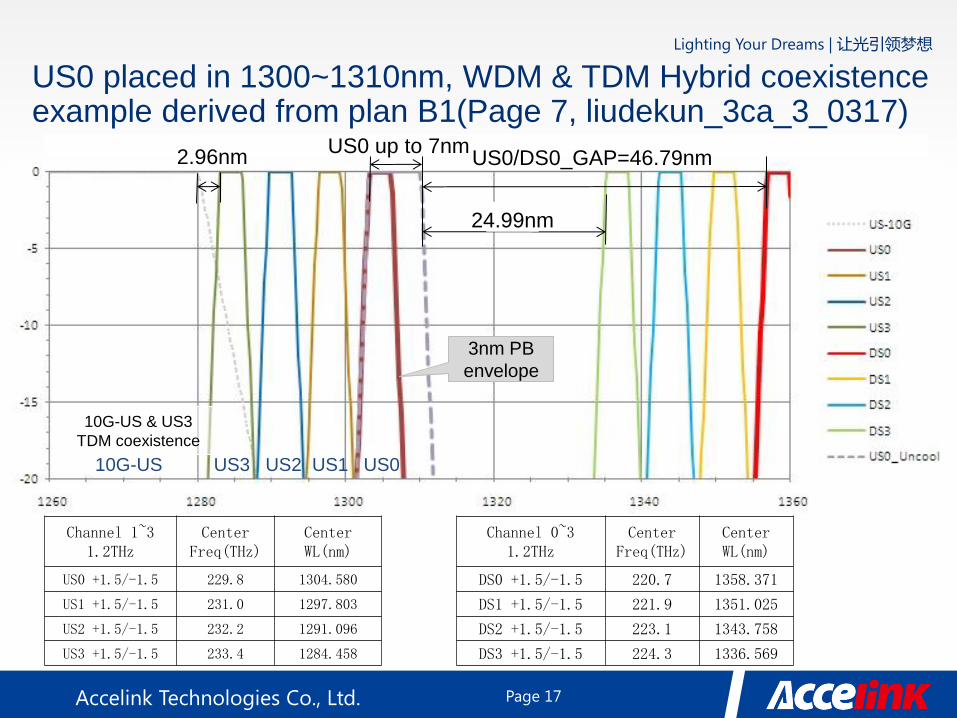
US0 placed in 1300~1310nm, WDM & TDM Hybrid coexistence example derived from plan B1(Page 7, liudekun_3ca_3_0317)
Channel 1~3 1.2THz
Center Freq(THz)
Center WL(nm)
US0 +1.5/-1.5 229.8 1304.580
US1 +1.5/-1.5 231.0 1297.803
US2 +1.5/-1.5 232.2 1291.096
US3 +1.5/-1.5 233.4 1284.458
US0/DS0_GAP=46.79nm
24.99nm
2.96nm US0 up to 7nm
10G-US US3 US2 US1 US0
3nm PB
envelope
Channel 0~3 1.2THz
Center Freq(THz)
Center WL(nm)
DS0 +1.5/-1.5 220.7 1358.371
DS1 +1.5/-1.5 221.9 1351.025
DS2 +1.5/-1.5 223.1 1343.758
DS3 +1.5/-1.5 224.3 1336.569
10G-US & US3
TDM coexistence
Page 17

Accelink Technologies Co., Ltd.
Lighting Your Dreams | 让光引领梦想
Pass band comparisons: 3nm/7nm/20nm
Different temperature control techniques are corresponding to different
TX SPECs and application scenarios
Upstream Pass band 3nm 7nm 20nm without Temp. control
Temperature range I-Temp. C-Temp. I-Temp. C-Temp. I-Temp. C-Temp.
Lowest cost Temp. control method
Full-scale TEC Full-scale TEC Miniature TEC Heater-only Uncooled Uncooled
Achievable TX SPECs Best Best Better than
BASIC Better than
BASIC Worse than
BASIC BASIC
Candidate TX SPECs Best Better than BASIC Worse than BASIC
Candidate RX SPECs with SOA Best Better than BASIC BASIC
Page 18
Accelink Technologies Co., Ltd.
Lighting Your Dreams | 让光引领梦想
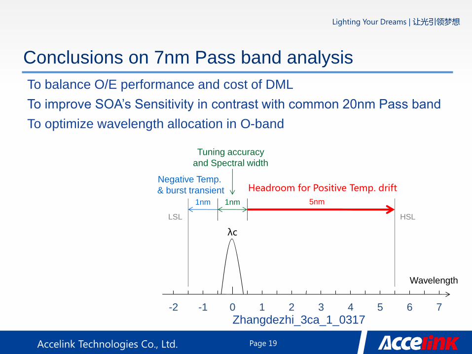
Conclusions on 7nm Pass band analysis
To balance O/E performance and cost of DML
To improve SOA’s Sensitivity in contrast with common 20nm Pass band
To optimize wavelength allocation in O-band
0 -1 -2 2 1 5 4 3 7 6
LSL HSL
Wavelength
λc
Negative Temp.
& burst transient Headroom for Positive Temp. drift
1nm 1nm
Tuning accuracy
and Spectral width
5nm
Zhangdezhi_3ca_1_0317
Page 19
Lighting Your Dreams | 让光引领梦想
Accelink Technologies Co., Ltd.
THANKS
Page 20