
F MODE D'EMPLOI P D BEDIENUNGSSANLEITUNGEN PL · La sottoscritta SANDRIGARDEN srl, via Manzoni 22,...
77
GBL 26 6021440/112 [B00325-02] GB 26 DECESPUGLIATORI BRUSH CUTTERS DEBROUSSAILLEUSES FREISCHNEIDER STRUIKENSNOEIERS DESBROZADORAS ROÇADORAS KOSIARKA MANUALE ISTRUZIONI INSTRUCTION MANUAL MODE D'EMPLOI BEDIENUNGSSANLEITUNGEN GB I F D NL E P PL BEDIENINGSHANDLEIDING MANUAL DE INSTRUCCIONES MANUAL DE INSTRUÇÕES INSTRUKCJA OBS£UGI Leggere attentamente le presenti istruzioni prima del primo impiego. Read this operators manual careful before the first use. Lire avec attention ces instructions avant la première utilisation Vor der Anwendung die vorliegenden Anweisungen aufmerksam lesen. Lees aandachtig deze instructies door alvorens het apparaat voor het eerst in gebruik te nemen. Leer con cuidado estas instrucciones antes de la primera utilización. Leia com atenção estas instruções antes de utilizar pela primeira vez o aparelho. Przed pierwszym u¿ytkowaniem uwa¿nie przeczytaæ niniejsz¹ instrukcjê. I GB F D NL E P PL GBL 34 GB 34
Transcript of F MODE D'EMPLOI P D BEDIENUNGSSANLEITUNGEN PL · La sottoscritta SANDRIGARDEN srl, via Manzoni 22,...

1/112
GBL 26
6021440/112[B00325-02]
GB 26
DECESPUGLIATORIBRUSH CUTTERSDEBROUSSAILLEUSESFREISCHNEIDERSTRUIKENSNOEIERSDESBROZADORASROÇADORASKOSIARKA
MANUALE ISTRUZIONIINSTRUCTION MANUALMODE D'EMPLOIBEDIENUNGSSANLEITUNGEN
GB
I
F
D
NL
E
P
PL
BEDIENINGSHANDLEIDINGMANUAL DE INSTRUCCIONESMANUAL DE INSTRUÇÕES���������� �����
Leggere attentamente le presentiistruzioni prima del primo impiego.Read this operators manual carefulbefore the first use.Lire avec attention ces instructionsavant la première utilisationVor der Anwendung die vorliegendenAnweisungen aufmerksam lesen.Lees aandachtig deze instructiesdoor alvorens het apparaat voor heteerst in gebruik te nemen.Leer con cuidado estasinstrucciones antes de la primerautilización.Leia com atenção estas instruções antesde utilizar pela primeira vez o aparelho.�������������� ���������� ����������������������������� �����
I
GB
F
D
NL
E
P
PL
GBL 34
GB 34

2/112
(I)ATTESTAZIONE DI CONFORMITÀ ALLE NORME CEELa sottoscritta SANDRIGARDEN srl, via Manzoni 22, 36027 ROSÀ (VI) ITALIA, dichiara che i seguenti prodotti:DECESPUGLIATORI CON MOTORE A SCOPPIO GB 26, GBL 26, GB 34, GBL 34 sono conformi alledirettive, 98/37/CEE, 89/336/CEE, ed è stato sviluppato conformemente alle norme EN ISO 11806
(ENG)EC DECLARATION OF CONFORMITYThe under signed SANDRIGARDEN srl, via Manzoni 22, 36027 ROSÀ (VI) ITALIA, declare that the followingproducts: COMBUSTION ENGINE DRIVEN BRUSH CUTTERS GB 26, GBL 26, GB 34, GBL 34 are in accordancewith the directive 98/37/EEC, 89/336/EEC and as been develloped in accordance with the standars EN ISO 11806.
(F)ATTESTATION DE CONFORMITE AUX NORMES CEELa soussignée SANDRIGARDEN srl, via Manzoni 22, 36027 ROSÀ (VI) ITALIE, déclare que ces produitsDEBROUSSAILLEUSE AVEC MOTEUR A EXPLOSION GB 26, GBL 26, GB 34, GBL 34 sont conformes auxdirectives, 98/37/CEE, 89/336/CEE, et conçu selon les normes EN ISO 11806
(D)KONFORMITÄTBESCHEINIGUNG ZU EWG-REGELUNGENDie unterschriebene Firma SANDRIGARDEN srl, via Manzoni 22, 36027 ROSÀ (VI) ITALIEN, erklärt hiermit, dassfolgendes Produkt:: FREISCHNEIDEGERÄTE MIT EXPLOSIONSMOTOR GB 26, GBL 26, GB 34, GBL 34 denRichtlinien 98/37/EWG, 89/336/EWG entspricht und dass es entsprechend den Standards EN ISO 11806 entwickeltwurde.(NL)CONFORMITEITSVERKLARING MET DE CEE NORMENOndergetekende SANDRIGARDEN srl, via Manzoni 22, 36027 ROSÀ (VI) ITALIË, verklaart dat de volgendeproducten: STRUIKENSNOEIERS MET VERBRANDINGSMOTOR GB 26, GBL 26, GB 34, GBL 34 conform zijnaan de richtlijnen 98/37/CEE, 89/336/CEE, en ontworpen zijn in overeenstemming met de normen EN ISO 11806
(E)CERTIFICACIÓN DE CONFORMIDAD CON LAS NORMAS CEELa abajo firmante SANDRIGARDEN srl, via Manzoni 22, 36027 ROSÀ (VI) ITALIA, declara que el siguiente producto:DESBROZADORAS CON MOTOR DE EXPLOSIÓN GB 26, GBL 26, GB 34, GBL 34 son conformes a lasdirectivas, 98/37/CEE, 89/336/CEE, y ha sido realizado de conformidad con las normas EN ISO 11806.
(P)ATESTADO DE CONFORMIDADE COM AS NORMAS CEEA abaixo assinada SANDRIGARDEN srl, via Manzoni 22, 36027 ROSÀ (VI) ITÁLIA, declara que os seguintesprodutos: ROÇADORAS COM MOTOR DE EXPLOSÃO GB 26, GBL 26, GB 34, GBL 34 estão conforme asdirectivas 98/37/CEE, 89/336/CEE, e foram desenvolvidos de maneira conforme as normas EN ISO 11806
(PL)������ !"���#$%&'%(� �#�'%�)") ������������������ �� SANDRIGARDEN srl, �������������������������������� !�"#�$%&��'(��)��������*�)�+,-�KOSIARKI Z SILNIKIEM ISKROWYM GB 26, GBL 26, GB 34, GBL 34�.��/�)�����) *�+, (�0��98/37/CEE, 89/336/CEE �����,�1 ��2�)�(�� ��/�)��������*0�0�EN ISO 11806
05 - 11 - 2001SANDRI GARDEN
srlDirettore GeneraleAlberto Cattaneo
3/112
14
22
8
9
Fig. 1
18
15 16 17
14
15
16
17
10
9
8
13 11
22
21
21
18
12
127
23
19
20
43
12
5
6
24
10
11

4/112
MANUALE ISTRUZIONI DECESPUGLIATORE
1. CONGRATULAZIONIGentile cliente, vogliamo congratularci con Lei peraver scelto un nostro prodotto per il giardino.Il Vostro DECESPUGLIATORE è statocostruito, tenendo conto delle norme di sicurezzavigenti a tutela del consumatore.
In questo manuale sono descritte ed illustrate levarie operazioni di montaggio, di uso ed interventidi manutenzione, necessari per mantenere in per-fetta efficienza il Vostro DECESPUGLIATORE.
PER FACILITARE LA LETTURALe illustrazioni corrispondenti almontaggio e alla descrizione della
macchina si trovano nel risvolto di copertina, all'ini-zio del presente fascicolo.Tenere aperte queste pagine durante la lettura del-le istruzioni di montaggio e di utilizzo.
Nel caso il Vostro DECESPUGLIATORE necessi-tasse di assistenza o riparazione, Vi preghiamo dirivolgervi al nostro rivenditore, o ad un centro assi-stenza autorizzato.
2. PRECAUZIONI FONDAMENTALIDI SICUREZZA
NORME GENERALI
AVVERTENZE:A1 - L'utilizzo del DECESPUGLIA-TORE richiede il rispetto delle norme disicurezza.A2 - Chiunque utilizzi ilDECESPUGLIATORE deve prima leg-gere attentamente il manuale di istru-
zioni e manutenzione e familiarizzarecompletamente con i comandi per unuso corretto dell'apparecchio.A2.1 - Conservare il presente manua-le per consultazioni future.A3 - Non permettere l'uso delDECESPUGLIATORE ai bambini epersone che non siano completamentea conoscenza delle presenti istruzioni.
PERICOLO:A4 - Fare attenzione al materiale pro-iettato dal dispositivo di taglio.A5 - Non mettere in moto e non utilizza-re il tagliaerba in prossimità di persone,animali o cose.Durante il funzionamento si raccoman-da una distanza minima di 15 m tra lamacchina ed altre persone.A6 - L'operatore è responsabile in casodi incidenti o pericoli occorsi ad altrepersone od alle loro cose.
UTILIZZO:B1 - Impiegare il DECESPUGLIATOREsolamente per tagliare erba ed erbaccee cespugli.Non impiegare l'apparecchio per scopidiversi.B2 - Indossare un'abbigliamento ed unequipaggiamento di sicurezza adattoall'utilizzo del DECESPUGLIATORE.Durante l'utilizzo indossare abiti ade-renti e non sciolti.B3 - Indossare occhiali di protezione ovisiera omologati.B3.1 - Indossare paraorecchi di prote-zione per il rumore, omologati.B3.2 - Indossare il casco di protezionein caso di rischio di caduta di oggetti.B4 - Calzare scarpe robuste con suolenon sdrucciolevoli.
I

5/112
MANUALE ISTRUZIONI DECESPUGLIATORE
B5 - Indossare guanti robusti.B6 - Chi utilizza il DECESPUGLIA-TORE deve essere in buona forma.NON UTILIZZARE il DECESPU-GLIATORE in condizioni di stanchez-za, di malessere o sotto l'effetto dell'alcole di altre droghe.B7 - ATTENZIONE! I gas di scaricosono velenosi ed asfissianti. Se inspi-rati possono quindi essere anche mor-tali. Non fare funzionare il motore in luo-go chiuso o scarsamente ventilato.B8 - L'utilizzo prolungato dell'apparec-chio può causare disturbi di circolazio-ne sanguigna alle mani (malattia delledita bianche) attribuibili alle vibrazioni.Fattori che influiscono sulla manifesta-zione dei disturbi possono essere:- Predisposizione personale dell'ope-ratore ad una scarsa irrorazione san-guigna delle mani.- Utilizzo dell'apparecchio a basse tempe-rature (si consigliano pertanto guanti caldi).- Lunghi tempi di utilizzo senza interru-zioni (si consiglia un utilizzo ad interval-li).- In caso di manifestazione di formicolioe intorpedimento si raccomanda di con-sultare un medico.B8.1 - Sostenere l'apparecchio sem-pre con ambedue le mani.Assumere una posizione stabile e sicu-ra sulle gambe.B8.2 - Il Decespugliatore è progettatoper essere utilizzato sul fianco destrodell'operatore (vedi fig. 37-38).Tenere l'impugnatura posteriore (con icomandi) con la mano destra e l'impu-gnatura anteriore con la mano sinistra.
B9 - ATTENZIONE! la benzina ei suoi vapori sono estremamente infiam-mabili.PERICOLO DI USTIONI ED INCENDIO.B9.1 - Arrestare il motore prima del ri-fornimento.B9.2 - Non fumare durante il riforni-mento di carburante.B9.3 - Asciugare il carburante even-tualmente rovesciato. Mettere in moto ilmotore lontano dal luogo di rifornimento.B9.4 - Assicurarsi che il tappo del ser-batoio sia ben serrato.Fare attenzione ad eventuali perdite.B10 - Con l'apparecchio è fornita unaPROTEZIONE DEL DISPOSITIVO DITAGLIO (Fig.1 part.21) che deve es-sere montata prima dell'utilizzo (vediistruzioni di montaggio).Non mettere in moto nè utilizzare l'ap-parecchio se non è provvisto di prote-zione.B10.1 - PERICOLO! Ferite dovute alcontatto con il dispositivo di taglio; pro-iezione di materiale verso l'operatore.Non modificare la protezione.Sostituire la protezione se danneggia-ta, solo con un ricambio originale.B10.2 - PERICOLO! Non montarefilo metallico nella testa di taglio.B10.3 - Il BLOCCO DEL COMANDODELL'ACCELERATORE (vedi fig.1part.16) impedisce l'azionamento acci-dentale della leva dell'acceleratore.B10.4 - INTERRUTTORE (ON/OFF)di arresto del motore (fig.1 part.14).PERICOLO! Attenzione il dispositivo ditaglio continua a girare per un certotempo anche dopo l'azionamento del-l'interruttore sulla posizione "OFF".
I

6/112
MANUALE ISTRUZIONI DECESPUGLIATORE
Tenere saldamente le due impugnatu-re fino al completo arresto. Vedi capito-lo AVVIAMENTO ED ARRESTO.B10.5 PERICOLO! Non montarelame a sega.B10.6 PERICOLO! Non montarelame costituite da più pezzi ma sololame monolitiche.B10.7 PERICOLO! Non montarelame con diametro superiore a230 mm.
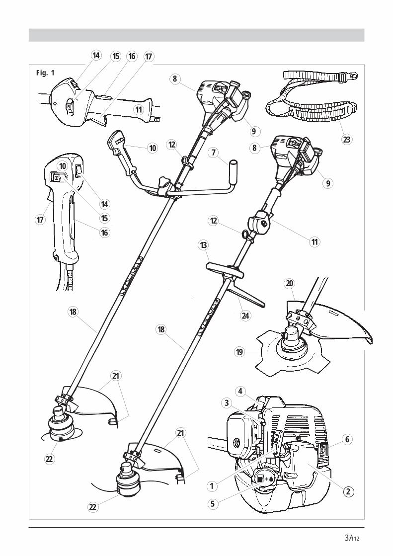
3. DESCRIZIONI PARTI MACCHINADESCRIZIONE Fig.1
1) Maniglia della fune di avviamento2) Avviatore3) Levetta dell'aria4) Cappuccio della candela5) Tappo serbatoio carburante6) Silenziatore7) Impugnatura sinistra (manubrio)8) Motore a scoppio9) Serbatoio carburante10) Impugnatura destra con comandi (manubrio)11) Impugnatura comandi posteriore12) Punto di attacco per cinghia13) Impugnatura anteriore14) Dispositivo di arresto del motore ON/OFF.15) Bloccaggio mezzo acceleratore16) Blocco del comando dell'acceletaore17) Leva dell'acceleratore18) Tubo di trasmissione (asta)19) Lama20) Protezione dispositivo di taglio (per lama)21) Protezione dispositivo di taglio (per testa a fili)22) Dispositivo di taglio (testa a fili)23) Imbracatura a cinghia24) Barriera
4. MONTAGGIOIMPUGNATURA ANTERIORE PER MODELLOGBL 26/341) Posizionare come illustrato nella fig.2 l'impugna-tura (part.1) e la barriera (part.2).2) Bloccare con le n°4 viti, rosette e dadi (fig.3)La barriera ha la funzione di assicurare unadistanza di sicurezza tra l'operatore ed il di-spositivo di taglio.
MANUBRIO CON IMPUGNATURA PER MODEL-LO GB 26/341) Il DECESPUGLIATORE viene imballato con ilmanubrio ripiegato (fig.4).2) Allentare il pomolo (fig.5) e ruotare il manubriotrasversalmente.3) Bloccare il manubrio serrando a fondo il pomolo(fig.6).Il manubrio può essere ripiegato per comodità ditrasporto o rimessaggio oltrechè regolato per unapiù comoda posizione di lavoro.
I DECESPUGLIATORI possono essere utilizzati:A. Per decespugliare, montando la lama e la prote-zione della lama (fig.1 part.19-20).B. Per il taglio di erba, montando la testa a fili el'estensione (fig.1 part.21-22), che viene avvitataalla stessa protezione.
ATTENZIONE! Le condizioni di sicurez-za previste dalle norme vigenti si veri-
ficano solo montando le protezioni come so-pra descritto.
I

7/112
MANUALE ISTRUZIONI DECESPUGLIATORE
MONTAGGIO LAMA E PROTEZIONE (fig.7-8)
ATTENZIONE! Calzare i guanti di sicu-rezza per ogni intervento di montag-gio e manutenzione sulla lama.
1) Inserire i due dadi quadrati nelle loro sedi nellaprotezione (fig.9).2) Posizionare la protezione sotto alla scatola ditrasmissione in alluminio (fig.10).3) Posizionare il morsetto superiore e bloccare conle viti (fig.11).4) Avvitare (con le 3 viti) il piattello fisso alla scatoladi trasmissione (fig.12-13).5) Infilare il piattello superiore (in alluminio fig.14)bloccalama sull'albero di uscita.6) Montare in successione la lama (fig.15) (centrar-la sull'apposita sporgenza del piattello) e quindi ilpiattello inferiore (fig.16) bloccalama, la coppetta(fig.17) e la vite sinistra.7) Serrare in senso antiorario con la chiave in do-tazione (fig.18).
MONTAGGIO TESTA A FILI E L'ESTENSIONE/PROTEZIONE (fig.19-20)1) Unire la protezione (fig.20 part.1) all'estensione(fig.20 part.2) e bloccare con le 3 viti e i dadi.2) Montare la protezione ed il piattello fisso comedescritto nei punti 1-2-3 del paragrafo MONTAG-GIO LAMA E PROTEZIONE.3) Infilare il piattello rotante (in plastica) sull'albero diuscita (fig.21).4) Avvitare (in senso antiorario) la testa a fili (fig.22).5) Inserire un cacciavite nell'apposita nicchia (fig.22part.1) per bloccare l'albero durante il serraggio.6) Serrare la testa a fili.
IMBRACATURA A CINGHIA E ANELLO DI AT-TACCO (fig.23)1) Fissare l'anello in plastica come illustrato in fig.23.2) Fissarlo tramite le viti e i dadi (fig.24). Prima dellamessa in moto regolare la posizione dell'anello perun buon bilanciamento.
5. RIFORNIMENTO CARBURANTE 1) ATTENZIONE! L'apparecchio è equi- paggiato di motore a scoppio a 2 tempi.
Il motore deve essere alimentato con una miscela dibenzina e olio per motori a 2 tempi, nelle seguentipercentuali.
Con olio normale per motore 2 tempi 1:25 (4%) Con olio a base sintetica per motore 2 tempi 1:40 (2,5%)
2) Miscelare agitando abbondantemente il conteni-tore prima di ogni rifornimento.
Fig.253) Preparare lamiscela carbu-rante e fare rifor-nimento solo al-l'aperto (fig.25).
4) Conservare il carburante in un contenitore pre-visto per questo uso e con tappo ben serrato.
6. AVVIAMENTO E ARRESTO
ATTENZIONE! Osservare scrupolosa-mente gli avvertimenti contenuti nel
precedente Cap. 2 PRECAUZIONI FONDAMEN-TALI DI SICUREZZA.
I

8/112
MANUALE ISTRUZIONI DECESPUGLIATORE
AVVIAMENTO A MOTORE FREDDO1) Premere l'interruttore di arresto (fig. 26) sullaposizione "ON".2) Sollevare la levetta dell'aria posta a destra delcoperchio del carburatore (fig.27) e portarla nellaposizione .3) Pressare a fondo ripetutamente il bulbo primer (fig.28) fino a quando il carburante ritorna nel serbatoioattraverso il secondo tubetto trasparente (fig.29).4) Afferrare l'impugnatura premendo con il palmo ilblocco acceleratore (fig.30), liberando in questo modoil movimento della leva acceleratore (fig.30 part.1).5) Premere a fondo la leva dell'acceleratore (fig.31).6) Mantenendo premute le leve (fig.31) spingere afondo il bottone del mezzo acceleratore (fig.32).7) Mantenendo a fondo il bottone rilasciare la levadell'acceleratore .In questo modo il bottone di blocco del mezzo acce-leratore rimane inserito, quindi le mani rimangonoentrambe disponibili per l'avviamento.8) Tirare a fondo fino a 3 volte la maniglia della funedi avviamento (fig.33).9) Spingere in giù la levetta dell'aria del carburato-re (fig.34).10) Tirare la fune di avviamento (fig.33) fino allamessa in moto.
ATTENZIONE - PERICOLO !! Il motore siavvia e rimane accelerato a metà quindi il
dispositivo di taglio è in rotazione.Lasciare funzionare il motore per alcuni secondi.
11) Premendo brevemente la leva acceleratore (fig.35 part.1) il bottone del mezzo acceleratore sidisinserisce automaticamente. Il motore rimane cosìin moto al regime minimo ed il dispositivo di taglio siarresta dopo un breve tempo.
ARRESTO MOTORE
1) Per arrestare il motore, portare l'iterruttore (fig.35 part. 2) nella posizione "OFF".
Fig.27
Fig.28 Fig.29
Fig.30 Fig.31
Fig.32
Fig.33
Fig.34 Fig.35
�
�
�
�
�
�
� �
�
1
2
1
Fig.26
�
ON
OFF
ON
OFF
I
9/112
MANUALE ISTRUZIONI DECESPUGLIATORE
ATTENZIONE! il dispositivo di taglio conti-nua a girare per un certo tempo anche
dopo l'azionamento dell'interruttore sulla posizione"OFF". Tenere saldamente le due impugnature finoal completo arresto.
AVVIAMENTO A MOTORE CALDOProcedere come a motore freddo ma con la levettadell'aria abbassata (vedi fig.34).
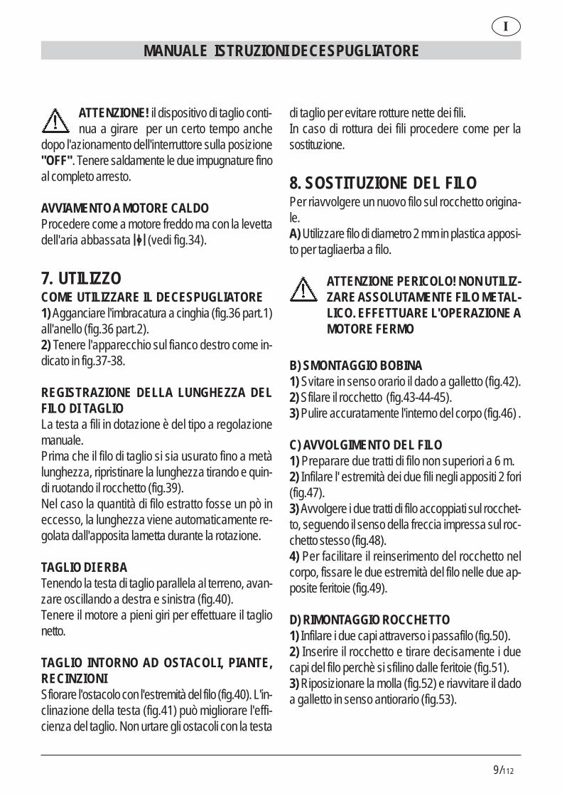
7. UTILIZZOCOME UTILIZZARE IL DECESPUGLIATORE1) Agganciare l'imbracatura a cinghia (fig.36 part.1)all'anello (fig.36 part.2).2) Tenere l'apparecchio sul fianco destro come in-dicato in fig.37-38.
REGISTRAZIONE DELLA LUNGHEZZA DELFILO DI TAGLIOLa testa a fili in dotazione è del tipo a regolazionemanuale.Prima che il filo di taglio si sia usurato fino a metàlunghezza, ripristinare la lunghezza tirando e quin-di ruotando il rocchetto (fig.39).Nel caso la quantità di filo estratto fosse un pò ineccesso, la lunghezza viene automaticamente re-golata dall'apposita lametta durante la rotazione.
TAGLIO DI ERBATenendo la testa di taglio parallela al terreno, avan-zare oscillando a destra e sinistra (fig.40).Tenere il motore a pieni giri per effettuare il taglionetto.
TAGLIO INTORNO AD OSTACOLI, PIANTE,RECINZIONISfiorare l'ostacolo con l'estremità del filo (fig.40). L'in-clinazione della testa (fig.41) può migliorare l'effi-cienza del taglio. Non urtare gli ostacoli con la testa
di taglio per evitare rotture nette dei fili.In caso di rottura dei fili procedere come per lasostituzione.
8. SOSTITUZIONE DEL FILOPer riavvolgere un nuovo filo sul rocchetto origina-le.A) Utilizzare filo di diametro 2 mm in plastica apposi-to per tagliaerba a filo.
ATTENZIONE PERICOLO! NON UTILIZ-ZARE ASSOLUTAMENTE FILO METAL-LICO. EFFETTUARE L'OPERAZIONE AMOTORE FERMO
B) SMONTAGGIO BOBINA1) Svitare in senso orario il dado a galletto (fig.42).2) Sfilare il rocchetto (fig.43-44-45).3) Pulire accuratamente l'interno del corpo (fig.46) .
C) AVVOLGIMENTO DEL FILO1) Preparare due tratti di filo non superiori a 6 m.2) Infilare l' estremità dei due fili negli appositi 2 fori(fig.47).3) Avvolgere i due tratti di filo accoppiati sul rocchet-to, seguendo il senso della freccia impressa sul roc-chetto stesso (fig.48).4) Per facilitare il reinserimento del rocchetto nelcorpo, fissare le due estremità del filo nelle due ap-posite feritoie (fig.49).
D) RIMONTAGGIO ROCCHETTO1) Infilare i due capi attraverso i passafilo (fig.50).2) Inserire il rocchetto e tirare decisamente i duecapi del filo perchè si sfilino dalle feritoie (fig.51).3) Riposizionare la molla (fig.52) e riavvitare il dadoa galletto in senso antiorario (fig.53).
I

10/112
9. MANUTENZIONECANDELAAlmeno una volta all'anno od in caso di difficoltà dimessa in moto, verificare lo stato della candela diaccensione. Attendere che il motore si raffreddi pri-ma dell'operazione.1) Sfilare il cappuccio e svitare la candela con lachiave in dotazione (fig.54).In caso di eccessive incrostazioni e notevole usuradegli elettrodi, sostituire la candela con una di tipoequivalente (fig.55-56).Un eccesso di incrostazioni può essere dovuta a:# Eccessiva percentuale di olio nel carburante e/oqualità non appropriata dell'olio.# Filtro aria parzialmente ostruito.2) Avvitare la candela a mano fino a fondo filetto perevitare danni alla sua sede. Usare l'apposita chia-ve solo per il serraggio (fig.54).
FILTRO ARIAPulire periodicamente il filtro aria; frequentementese si opera in aree polverose.1) Svitare la vite a galletto del coperchio (fig.57).2) Lavare con acqua e detergente neutro.3) Fare asciugare il filtro prima di riposizionarlo(fig.58).Sostituire il filtro se danneggiato per noncompromettere la durata del motore.
FILTRO PESCANTE DEL CARBURANTESostituire una volta all'anno il filtro estraendolo conun gancio attraverso l'apertura di rifornimento delserbatoio.
RETINA PARASCINTILLE DEL SILENZIATO-RE# Nel foro di scarico del gas è inserito un anello conretina (parte più sporgente).# A causa dei depositi la retina tende a ostruirsi
riducendo notevolmente le prestazioni del motore.# Estrarre l'anello con retina per mezzo di una pinzaa becchi (fig.59).
REGIME MINIMO DEL MOTORE# Verificare ad ogni utilizzo che al regime-minimo il dispositivo di taglio non sia in rota-zione.
# Se tende a ruotare rivolgersi ad un centro di assi-stenza per l'intervento di regolazione.
VERIFICA VITI E PARTI ROTANTI# Prima di ogni utilizzo controllare che non ci sianoviti o parti allentate e che non ci siano cricche onotevoli usure nel dispositivo di taglio.# Sostituire le parti danneggiate prima dell'utilizzo.
PULIZIA TRASPORTO E RIMESSAGGIO# In caso di interruzione di utilizzo superiore a 2mesi, vuotare il serbatoio del carburante.# Non pulire con liquidi aggressivi.# Conservare l'apparecchio in luogo asciutto e si-curo non accessibile ai bambini.# In occasione di trasporto vuotare il serbatoio car-burante e proteggere la lama (se montata) con unapposita protezione.
MANUALE ISTRUZIONI DECESPUGLIATORE
I

11/112
MANUALE ISTRUZIONI DECESPUGLIATORE
I
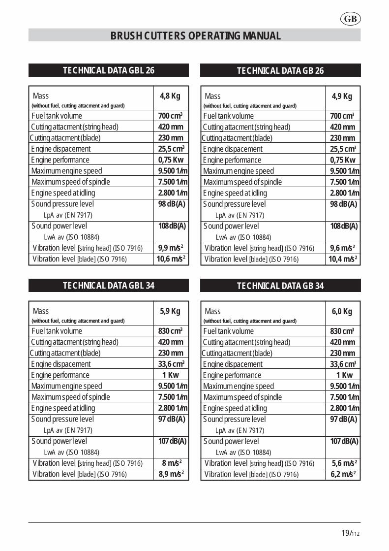
DATI TECNICI GBL 26
Massa 4,8 Kg (senza carburante - dispositivo di taglio - protezione)
Capacità serbatoio 700 cm3
Dispositivo di taglio (testa a fili) 420 mm Dispositivo di taglio (lama) 230 mm Cilindrata motore 25,5 cm3
Potenza massima 0,75 Kw Regime massimo del motore 9.500 1/min Regime massimo del dispositivo di taglio 7.500 1/min Regime di minimo 2.800 1/min Livello di pressione acustica 98 dB(A) LpA av (EN 7917)
Livello di potenza acustica 108 dB(A) LwA av (ISO 10884) Livello vibrazioni max [testa a fili] 9,9 m/s2
(ISO 7916) Livello vibrazioni max [lama] 10,6 m/s2
(ISO 7916)
DATI TECNICI GB 26
Massa 4,9 Kg (senza carburante - dispositivo di taglio - protezione)
Capacità serbatoio 700 cm3
Dispositivo di taglio (testa a fili) 420 mm Dispositivo di taglio (lama) 230 mm Cilindrata motore 25,5 cm3
Potenza massima 0,75 Kw Regime massimo del motore 9.500 1/min Regime massimo del dispositivo di taglio 7.500 1/min Regime di minimo 2.800 1/min Livello di pressione acustica 98 dB(A) LpA av (EN 7917)
Livello di potenza acustica 108 dB(A) LwA av (ISO 10884)
Livello vibrazioni max [testa a fili] 9,6 m/s2
(ISO 7916)
Livello vibrazioni max [lama] 10,4 m/s2
(ISO 7916)
DATI TECNICI GBL 34
Massa 5,9 Kg (senza carburante - dispositivo di taglio - protezione)
Capacità serbatoio 830 cm3
Dispositivo di taglio (testa a fili) 420 mm Dispositivo di taglio (lama) 230 mm Cilindrata motore 33,6 cm3
Potenza massima 1 Kw Regime massimo del motore 9.500 1/min Regime massimo del dispositivo di taglio 7.500 1/min Regime di minimo 2.800 1/min Livello di pressione acustica 97 dB(A) LpA av (EN 7917)
Livello di potenza acustica 107 dB(A) LwA av (ISO 10884) Livello vibrazioni max [testa a fili] 8 m/s2
(ISO 7916)
Livello vibrazioni max [lama] 8,9 m/s2
(ISO 7916)
DATI TECNICI GB 34
Massa 6,0 Kg (senza carburante - dispositivo di taglio - protezione)
Capacità serbatoio 830 cm3
Dispositivo di taglio (testa a fili) 420 mm Dispositivo di taglio (lama) 230 mm Cilindrata motore 33,6 cm3
Potenza massima 1 Kw Regime massimo del motore 9.500 1/min Regime massimo del dispositivo di taglio 7.500 1/min Regime di minimo 2.800 1/min Livello di pressione acustica 97 dB(A) LpA av (EN 7917)
Livello di potenza acustica 107 dB(A) LwA av (ISO 10884)
Livello vibrazioni max [testa a fili] 5,6 m/s2
(ISO 7916)
Livello vibrazioni max [lama] 6,2 m/s2
(ISO 7916)

12/112
1. CONGRATULATIONSDear Client - May we congratulate you for havingchosen one of our products for your garden.Your GBL 26/34,GB26/34 BRUSH CUTTERShas been manufactured in accordance with thecurrent safety regulations which protect theconsumer.
This manual describes and illustrates the variousoperations for assembly, use and maintenance whichare required in order to keep your BRUSHCUTTERS in perfect condition.
TO FACILITATE READINGThe illustrations about the assemblyare to be found on the back of
cover, at the beginning of this booklet. Keep thesepages open while reading the assembly instructions.
Should your BRUSH CUTTERS need servicingor repair, please contact your retailer or anauthorised service centre.
2.ESSENTIAL SAFETY PRECAU-TIONS
GENERAL REGULATIONS
PRECAUTIONS:A1 - Safety regulations must be heededwhen using the BRUSH CUTTERS.A2 - All users of the BRUSH CUTTERSmust first carefully read the maintenanceand operating manual and familiarisethemselves fully with all controls forcorrect operation of the device.A2.1 - Keep this manual for futurereference.
A3 - Do not let children and personswho are not completely aware of theseinstructions use the BRUSHCUTTERS.
DANGER:A4 - Beware of objects hurled by theline head.A5 - Do not start up and do not use thegrass trimmer near people, otheranimals or obtrusive objects.During operation we recommendkeeping a minimum distance of 15 mbetween the machine and other people.A6 - The operator is responsible forany accidents or hazards that mayoccur to other persons or theirbelongings.
OPERATION:B1 - Use the BRUSH CUTTER only tocut grass, weeds and bushes.Do not use the device for otherpurposes.B2 - Wear clothing and safety gearsuitable for BRUSH CUTTERSoperation.During operation wear close-fittingclothing and not loose or baggygarments.B3 - Wear approved protective gogglesor visor.B3.1 - Wear approved noise-dampingearplugs.B3.2 - Wear a safety helmet in areaswhere objects are likely to fall.B4 - Wear sturdy shoes with non-slipsoles.B5 - Wear sturdy gloves.B6 - BRUSH CUTTERS operators mustbe in good physical condition. DO NOTUSE the BRUSH CUTTERS if you feel
BRUSH CUTTERS OPERATING MANUAL
GB

13/112
BRUSH CUTTERS OPERATING MANUAL
tired, ill or are under the influence ofalcohol or other drugs.B7 - CAUTION! Exhaust fumes aretoxic and asphyxiating. If inhaled, thesefumes may even be lethal. Do not startthe engine in closed or poorly ventilateenvironments.B8 - Prolonged use of the device mayhinder blood circulation to the hands(Raynaud’s phenomenon) due tovibrations.The following factors may pose a risk tothe operator’s health:- Operator is predisposed to poor bloodcirculation in the hands.- The device is used in cold weather(warm gloves are stronglyrecommended).- The device is used non-stop for longperiods (we suggest using it atintervals).- If you feel a tingling sensation or numbin any way, please seek medicalattention.B8.1 - Always hold the device with bothhands.Stand in a safe and steady position onboth legs.B8.2 - The grass trimmer is designedto be used on your right-hand side (seefig. 37-38).Hold the rear handle with controls withyour right hand and the front handlewith your left hand.B9 - CAUTION! Petrol and its vapoursare highly flammable.BURNING AND FIRE HAZARDS.B9.1 - Stop the engine before refuelling.B9.2 - Do not smoke while refuelling.B9.3 - Wipe off any fuel that may have
spilled. Start up the engine away fromthe place where it was refuelled.B9.4 - Make sure the tank cap istightened properly.Beware of any leaks.B10 - The device is supplied with aCUTTING ATTACHMENT GUARD(Fig.1 item21) that must be mountedbefore operation (see assemblyinstructions).Do not start up or use the device if it isnot equipped with the guard.B10.1 - DANGER! Injuries caused bycontact with the line head. Guardagainst objects hurled towards theoperator.Do not modify the guard.If damaged, replace the guard only withan original spare part.B10.2 - DANGER! Do not fit metalwire in the line head.B10.3 - The THROTTLE TRIGGERLOCKOUT (see fig.1 item 16) stopsaccidental operation of the throttlecontrol lever.B10.4 - Engine power ON/OFFSWITCH (fig.1 item14).DANGER! Caution! The line headcontinues to spin for a while even afterthe power switch has been shut OFF.Hold both handles firmly until the linehead comes to a complete stop. Seesection titled STARTING ANDSTOPPING.B10.5 DANGER! Do not fit saw blades.B10.6 DANGER! Do not fit bladescomposed of many parts but only singleblades.
GB

14/112
B10.7 DANGER! Do not fit bladeswith a diameter greater than 230mm.
3. DESCRIPTIONS OF MACHINEPARTSDESCRIPTION Fig.11) Starter grip2) Starter3) Chock lever4) Spark plug cap5) Fuel cap6) Silencer7) Left grip (handle bar)8) Combustion engine9) Fuel tank10) Right handle with controls (handle bar)11) Rear handle with controls12) Suspension point13) Front handle14) Engine stopping device (OFF/ON swithc).15) Throttle lock16) Throttle trigger lock out17) Throttle control lever18) Shaft tube19) Blade20) Cutting attachment guard (for blade)21) Cutting attachment guard (for line head)22) Line head23) Belt harness24) Barrier
4. ASSEMBLYFRONT HANDLE FOR MODEL GBL 26/341) Position the handle (item 1) and the guard (item2) as illustrated in fig.2.2) Clamp with 4 screws, washers and nuts (fig.3)The guard is used to maintain a safe distancebetween the operator and the cutting tool.
HANDLE FOR MODEL GB 26/341) The BRUSH CUTTER is packaged with a foldedhandle (fig.4).2) Loosen the knob (fig.5) and turn the handlecrosswise.3) Lock the handle by tightening the knob (fig.6) fully.The handle can be folded back for ease of transportor storage and can be adjusted for a morecomfortable working position.
BRUSH CUTTERS GB 26/34 and GBL 26/34may be used:A. To trim bushes, by fitting the blade and the bladeguard (fig.1 item 19-20).B. To trim grass by fitting the line head and theextension (fig.1 item 21-22), that is screwed onto thesame guard.
CAUTION! Safe operating conditionsestablished by effective regulationsare only met if guards are fitted asdescribed above.
BLADE AND GUARD ASSEMBLY (fig.7-8)
CAUTION! Wear safety gloves forassembly and maintenance jobs on theblade.
1) Fit the two square nuts into their threads on theguard (fig.9).
BRUSH CUTTERS OPERATING MANUAL
GB

15/112
2) Place the guard under the aluminium gearbox(fig.10).3) Place the top clamp and lock with screws (fig.11).4) Screw the fixed deflector onto the gearbox (fig.12-13) (with 3 screws).5) Insert the alluminium blade-lock upper collar(fig.14) in the drive shaft.6) In the following order fit the blade (fig.15) (centreit on the nib of the collar) and then the (fig.16) bladelock lower flange, the plate (fig.17) and the left screw.7) Tighten anticlockwise with the wrench provided(fig.18).
LINE HEAD ASSEMBLY AND EXTENSION /GUARD (fig.19-20)1) Join the guard (fig.20 item 1) to the extension(fig.20 item 2) and clamp with 3 screws and nuts.2) Assemble the guard and the fixed deflector asdescribed in points 1-2-3 of the paragraph titledBLADE AND GUARD ASSEMBLY.3) Install the (plastic) rotary flange in the drive shaft(fig.21).4) Screw on the line head (fig.22) anticlockwise.5) Insert a screwdriver in the relevant notch (fig.22item 1) to lock the shaft when tightening attachments.6) Tighten the line head.
BELT HARNESS AND SUSPENSION RING(fig.23)1) Attach the plastic ring as illustrated in fig.23.2) Attach it with screws and nuts (fig.24). Beforestarting the brush cutter, adjust the position of thering to ensure good balance.
BRUSH CUTTERS OPERATING MANUAL
5. REFUELLING 1) CAUTION! The device is equipped with a two-stroke engine.
The engine must be supplied with a mixture of petroland oil for two-stroke engines in the following ratios.
With normal oil for two-stroke engines 1:25 (4%) With synthetic oil for two-stroke engines 1:40 (2.5%)
2) Mix by stirring the container thoroughly beforerefilling the tank.3) Prepare the fuel mixture and only refuel outdoors(fig.25).4) Store the fuel in a container set aside for thispurpose and with tightly sealed cap.
Fig.25
GB

16/112
6. STARTING AND STOPPING
CAUTION! Strictly heed the warningsoutlined in the chapter 2 above titled
ESSENTIAL SAFETY PRECAUTIONS.
COLD ENGINE STARTUP1) Press the stop button (fig.26) to the “ON” position.2) Lift the choke lever located to the right of thecarburettor cover (fig.27) and place it in the position.3) Repeatedly press the primer bulb (fig.28) downuntil the fuel returns to the tank through the secondtransparent hose (fig.29).4) Grip the handle by pressing the throttle triggerlock out (fig. 30) with the palm of your hand, thusallowing you to move throttle control lever (fig.30item 1) freely.5) Press the throttle control lever right down (fig.31).6) Hold the levers (fig.31) down and push the throttlelock button (fig.32) right down.7) Hold the button down and release the throttlecontrol lever.This should lock the throttle lock button, so both handsare free to operate the device.8) Pull the starter grip (fig.33) completely as manyas 3 times.9) Push the carburettor choke lever (fig.34) down .10) Pull the start cord (fig.33) until the engine starts up.
CAUTION - DANGER !! The engine startsat half acceleration and as a result the line
head is spinning.Let the engine run a few seconds.
11) Press the throttle contol lever briefly (fig. 35item1) and the throttle lock button will disengageautomatically. The engine will thus return to idle andthe line head will stop after a short while.
BRUSH CUTTERS OPERATING MANUAL
Fig.27
Fig.28 Fig.29
Fig.30 Fig.31
Fig.32
Fig.33
Fig.34 Fig.35
�
�
�
�
�
�
� �
�
1
2
1
Fig.26
�
ON
OFF
ON
OFF
STOP ENGINE
1) To stop the engine, shut the power switch (fig. 35item 2) “OFF”.
GB

17/112
CAUTION! The line head continues to spinfor a while even after the power switch has
been shut OFF. Hold both handles firmly until theline head comes to a complete stop.
WARM ENGINE STARTUPProceed as with a cold engine startup but with thechoke lever down (see fig.34).
7. OPERATIONHOW TO USE THE BRUSH CUTTERS1) Couple the belt harness (fig.36 item 1) to the ring(fig.36 item 2).2) Hold the appliance on the right side as shown infig.37-38.
ADJUSTING THE LENGTH OF THE CUTTINGLINEThe line head supplied requires manual adjustment.Before the cutting line has worn as far as halfwayrestore the length by pulling and then turning thespool (fig.39).If too much line is pulled out, the length is automaticallyadjusted by the limiter blade during rotation.
TRIMMING GRASSWith the line head held parallel to the ground,proceed swinging the trimmer to the right and left(fig. 40). Keep the engine running at full speed for aclean trim.
TRIMMING AROUND OBSTACLES, PLANTSAND FENCESKeep the end of the line (fig. 40) just clear of obstacles.The inclination of the head (fig. 41) may improvetrimming efficiency. Do not knock obstacles with theline head to avoid cutting lines.Should lines snap, replace them as outlined below.
8. REPLACING A CUTTING LINEFor rewinding a new line on the original spool:A) Use a plastic line 2 mm in diameter speciallydesigned for strimmers.
ATTENTION DANGER! DO NOT USEMETAL WIRE AT ALL! DO THIS JOBWITH THE ENGINE OFF
B) DETACHING A SPOOL1) Unscrew the wing nut (fig.42) clockwise.2) Remove the spool (fig.43-44-45).3) Thoroughly clean the inside of the housing(fig.46).
C) WINDING A LINE1) Prepare two sections of line not over 6 m inlength.2) Insert the end of the two lines into the 2 holes(fig.47) provided.3) Wind the two coupled lengths of line on the spool,following the direction of the arrow printed on thespool itself (fig. 48).4) To make it easier to reinstall the spool in thehousing, attach both ends of the line in the two slotsprovided (fig.49).
D) REFITTING A SPOOL1) Insert both ends through the guiding eyelet(fig.50).2) Install the spool and pull boths end of the linefirmly until they hang out of the slots (fig.51).3) Refit the spring (fig.52) and screw the wing nutback (fig.53) on anti-clock wise.
BRUSH CUTTERS OPERATING MANUAL
GB

18/112
9.MAINTENANCESPARK PLUGAt least once a year or if the engine has problemsstarting up properly, check the condition of the sparkplug. Wait for the engine to cool before operation.1) Remove the cap and unscrew the spark plugwith the wrench provided (fig. 54).If the electrodes are excessively soiled or are veryworn, replace the spark plug with an equivalent(fig. 55-56).Excessive soiling may be due to:# The oil ratio used in fuel is too high and/or oil is notof an appropriate type.# Air filter is partly clogged.2) Screw the spark plug manually as far as possibleto avoid damaging its socket. Use the wrenchprovided only to tighten it (fig. 54).
AIR FILTERClean the air filter periodically or frequently whenworking in dusty areas.1) Unscrew the wing nut from the cover (fig.57).2) Wash with water and neutral detergent.3) Dry the filter before replacing it (fig.58).Replace the filter if it is damaged so as notcompromise engine life.
FUEL INTAKE FILTERReplace the filter once a year by removing it with ahook through tank-refilling outlet.
SILENCER SPARK ARRESTER SCREEN# A ring with a screen is inserted in the exhaust gasoutlet (outermost part).# Deposits tend to block the screen and considerablyreduce engine performance.# Remove the ring with a screen using a pair ofpliers (fig.59).
BRUSH CUTTERS OPERATING MANUAL
ENGINE IDLING SPEED# Before use, always make sure the linehead does not turn when the engine is idling.
# If it tends to turn, contact a service centre foradjustment.
CHECKING SCREWS AND ROTATING PARTS# Before use, always make sure there are no screwsor loose parts and there are no cracks or wornsections in the line head.# Replace any damaged parts before reuse.
CLEANING, TRANSPORT AND STORAGE# If the trimmer is not used for over 2 months, emptythe fuel tank.# Do not clean with aggressive liquids.# Store the device in a dry and safe place inaccessibleto children.# For transportation, empty the fuel tank and protectthe blade (if fitted) with a special guard.
TECHNICAL DATA GBL 26
GB
19/112
BRUSH CUTTERS OPERATING MANUAL
GB
Mass 4,8 Kg (without fuel, cutting attacment and guard)
Fuel tank volume 700 cm3
Cutting attacment (string head) 420 mm Cutting attacment (blade) 230 mm Engine dispacement 25,5 cm3
Engine performance 0,75 Kw Maximum engine speed 9.500 1/m Maximum speed of spindle 7.500 1/m Engine speed at idling 2.800 1/m Sound pressure level 98 dB(A) LpA av (EN 7917)
Sound power level 108 dB(A) LwA av (ISO 10884)
Vibration level [string head] (ISO 7916) 9,9 m/s2
Vibration level [blade] (ISO 7916) 10,6 m/s2
TECHNICAL DATA GB 26
Mass 4,9 Kg (without fuel, cutting attacment and guard)
Fuel tank volume 700 cm3
Cutting attacment (string head) 420 mm Cutting attacment (blade) 230 mm Engine dispacement 25,5 cm3
Engine performance 0,75 Kw Maximum engine speed 9.500 1/m Maximum speed of spindle 7.500 1/m Engine speed at idling 2.800 1/m Sound pressure level 98 dB(A) LpA av (EN 7917)
Sound power level 108 dB(A) LwA av (ISO 10884)
Vibration level [string head] (ISO 7916) 9,6 m/s2
Vibration level [blade] (ISO 7916) 10,4 m/s2
TECHNICAL DATA GBL 26 TECHNICAL DATA GB 26
Mass 5,9 Kg (without fuel, cutting attacment and guard)
Fuel tank volume 830 cm3
Cutting attacment (string head) 420 mm Cutting attacment (blade) 230 mm Engine dispacement 33,6 cm3
Engine performance 1 Kw Maximum engine speed 9.500 1/m Maximum speed of spindle 7.500 1/m Engine speed at idling 2.800 1/m Sound pressure level 97 dB(A) LpA av (EN 7917)
Sound power level 107 dB(A) LwA av (ISO 10884)
Vibration level [string head] (ISO 7916) 8 m/s2
Vibration level [blade] (ISO 7916) 8,9 m/s2
TECHNICAL DATA GB 26
Mass 6,0 Kg (without fuel, cutting attacment and guard)
Fuel tank volume 830 cm3
Cutting attacment (string head) 420 mm Cutting attacment (blade) 230 mm Engine dispacement 33,6 cm3
Engine performance 1 Kw Maximum engine speed 9.500 1/m Maximum speed of spindle 7.500 1/m Engine speed at idling 2.800 1/m Sound pressure level 97 dB(A) LpA av (EN 7917)
Sound power level 107 dB(A) LwA av (ISO 10884)
Vibration level [string head] (ISO 7916) 5,6 m/s2
Vibration level [blade] (ISO 7916) 6,2 m/s2
TECHNICAL DATA GBL 34 TECHNICAL DATA GB 34
20/112
MANUEL D'INSTRUCTION DE LA DEBROUSSAILLEUSE
F
d’instruction et d’entretien afin d’appren-dre parfaitement les commandes pourune utilisation correcte de la machine.A2.1 - Garder ce manuel pour le con-sulter à l’avenir.A3 - L’utilisation de laDEBROUSSAILLEUSE est interditeaux enfants et aux personnes qui neconnaissent pas ces instructions.
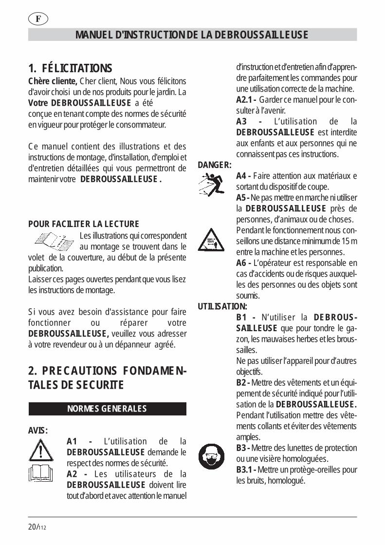
DANGER:A4 - Faire attention aux matériaux esortant du dispositif de coupe.A5 - Ne pas mettre en marche ni utiliserla DEBROUSSAILLEUSE près depersonnes, d’animaux ou de choses.Pendant le fonctionnement nous con-seillons une distance minimum de 15 mentre la machine et les personnes.A6 - L’opérateur est responsable encas d’accidents ou de risques auxquel-les des personnes ou des objets sontsoumis.
UTILISATION:B1 - N ’utiliser la DEBROUS-SAILLEUSE que pour tondre le ga-zon, les mauvaises herbes et les brous-sailles.Ne pas utiliser l’appareil pour d’autresobjectifs.B2 - Mettre des vêtements et un équi-pement de sécurité indiqué pour l’utili-sation de la DEBROUSSAILLEUSE.Pendant l’utilisation mettre des vête-ments collants et éviter des vêtementsamples.B3 - Mettre des lunettes de protectionou une visière homologuées.B3.1 - Mettre un protège-oreilles pourles bruits, homologué.
1. FÉLICITATIONSChère cliente, Cher client, Nous vous félicitonsd'avoir choisi un de nos produits pour le jardin. LaVotre DEBROUSSAILLEUSE a étéconçue en tenant compte des normes de sécuritéen vigueur pour protéger le consommateur.
Ce manuel contient des illustrations et desinstructions de montage, d'installation, d'emploi etd'entretien détaillées qui vous permettront demaintenir votre DEBROUSSAILLEUSE .
POUR FACILITER LA LECTURELes illustrations qui correspondentau montage se trouvent dans le
volet de la couverture, au début de la présentepublication.Laisser ces pages ouvertes pendant que vous lisezles instructions de montage.
Si vous avez besoin d'assistance pour fairefonctionner ou réparer votreDEBROUSSAILLEUSE, veuillez vous adresserà votre revendeur ou à un dépanneur agréé.
2. PRECAUTIONS FONDAMEN-TALES DE SECURITE
NORMES GENERALES
AVIS:A1 - L’utilisation de laDEBROUSSAILLEUSE demande lerespect des normes de sécurité.A2 - Les utilisateurs de laDEBROUSSAILLEUSE doivent liretout d’abord et avec attention le manuel
21/112
F
MANUEL D'INSTRUCTION DE LA DEBROUSSAILLEUSE
B3.2 - Mettre le casque de protection sides objets risquent de tomber.B4 - Mettre des chaussures robustesavec des semelles anti-dérapage.B5 - Mettre des gants robustes.B6 - Les utilisateurs de laDEBROUSSAILLEUSE doivent êtreen forme. NE PAS UTILISER laDEBROUSSAILLEUSE en cas defatigue, de malaise, sous l’effet de l’al-cool et d’autres drogues.B7 - ATTENTION! les gaz d’échappe-ment sont toxiques et asphyxiants; unefois inspirés, ils peuvent être mortels.Le moteur ne doit jamais fonctionnerdans un endroit fermé et peu ventilé.B8 - L’utilisation prolongée de l’appa-reil peut provoquer des troubles de lacirculation sanguine des mains (mala-die des doigts blancs) provoqués parles vibrations.Des facteurs qui exercent un impact surla manifestation peuvent être les sui-vants.- Prédisposition personnelle de l’opé-rateur à une mauvaise circulation san-guine dans les mains.- Utilisation de l’appareil à de bassestempératures (nous conseillons doncdes gants chauds).- De longues périodes d’utilisation sansinterruption (nous conseillons une utili-sation à intervalles).- En cas de fourmillement et engourdis-sement, nous conseillons de s’adres-ser à un médecin.B8.1 - Prendre toujours l’appareil avecles deux mainsPrendre un position stable et sûre surles jambes.
B8.2 - La DEBROUSSAILLEUSE estconçue pour une utilisation du côté droitde l’opérateur (voir fig. 37-38).Tenir la poignée postérieure (aveccommandes) avec la main droite et lapoignée antérieure avec la main gau-che.B9 - ATTENTION! l’essence et sesvapeurs sont très inflammables.RISQUES DE BRULURES ET D’IN-CENDIEB9.1 - Arrêter le moteur avant le ravi-taillement.B9.2 - Ne pas fumer pendant le ravi-taillement de carburant.B9.3 - Sécher le carburant éventuelle-ment renversé. Mettre en marche lemoteur loin du lieu de ravitaillement.B9.4 - S’assurer que le bouchon duréservoir est bien serré.Faire attention à toute perte de carbu-rant.B10 - L’appareil est fourni avec unePROTECTION DU DISPOSITIF DECOUPE (Fig.1 dét.21) qui doit êtremontée avant son utilisation (voir ins-tructions de montage).Ne pas mettre en marche ni utiliser l’ap-pareil sans protection.B10.1 - DANGER! Blessures provo-quées par le contact avec le dispositifde coupe; matériaux éjectés vers l’opé-rateur.Ne pas modifier la protection.Ne remplacer toute protection endom-magée que par une rechange origi-nale.B10.2 - DANGER! Ne pas monter lefil en métal dans la tête de coupe.B10.3 - LE BLOCAGE DE LA COM-MANDE DE L’ACCELERATEUR (voir

22/112
MANUEL D'INSTRUCTION DE LA DEBROUSSAILLEUSE
F
fig.1 dét.16): empêche l’actionnementaccidentel du levier de l’accélérateur.B10.4 - INTERRUPTEUR (ON/OFF)d’arrêt du moteur (fig.1 dét.14).DANGER! Attention: le dispositif decoupe continue à tourner pour quel-ques instants même aprèsl’actionnement de l’interrupteur en po-sition «OFF». Tenir solidement les deuxpoignées jusqu’à l’arrêt complet. Voir lechapitre DEMARRAGE ET ARRET.B10.5 DANGER! Ne pas monter deslames à scie.B10.6 DANGER! Monter seulementdes lames monolithiques et nonpas des lames multiples.B10.7 DANGER! Ne pas monter deslames ayant un diamètre supérieurà 230 mm.
3. DESCRIPTION PARTIESMACHINE
DESCRIPTION Fig.11) Poignée du câble de démarrage2) Démarreur3) Levier d’air (starter)4) Capuchon de la bougie5) Bouchon réservoir carburant6) Silencieux7) Poignée gauche (guidon)8) Moteur à explosion9) Réservoir carburant10) Poignée droite avec commandes
(guidon)11) Poignée commandes postérieure12) Point de fixation pour la courroie13) Poignée antérieure14) Dispositif d’arrêt du moteur ON/OFF.15) Blocage accélérateur16) Blocage commande accélérateur
17) Levier de l’accélérateur18) Tube de transmission (barre)19) Lame20) Protection dispositif de coupe (pour lame)21) Protection dispositif de coupe (pour tête à
fils)22) Dispositif de coupe (tête à fils)23) Harnais de securite24) Barrière
4. MONTAGEPOIGNEE AVANT POUR MODELE GBL 26/341) Positionner selon les indications de la fig.2 lapoignée (dét.1) et la barrière (dét.2).2) Bloquer par les 4 vis, les rondelles et les écrous(fig.3)La barrière assure une distance de sécuritéentre l’opérateur et le dispositif de coupe.
GUIDON AVEC POIGNEE POUR MODELE GB26/341) La DEBROUSSAILLEUSE est emballée avecle guidon replié (fig.4).2) Desserrer le pommeau (fig.5) et tourner le gui-don transversalement.3) Pour bloquer le guidon serrer à fond le pom-meau (fig.6).Le guidon peut être replié pour un transport ou unremisage plus facile, ou bien réglé pour une posi-tion de travail plus confortable.
Les DEBROUSSAILLEUSES GB26/34,GBL26/34peuvent être utilisées:A. Pour débroussailler, monter la lame et la protec-tion de celle-ci (fig.1 dét.19-20).B. Pour tondre le gazon: monter la tête à fils et sonextension (fig.1 dét.21-22), qui est vissée à la mêmeprotection.

23/112
F
MANUEL D'INSTRUCTION DE LA DEBROUSSAILLEUSE
ATTENTION! Les conditions de sécurité prévues par les normes en vi-
gueur ne peuvent être contrôlées que par lemontage des protections selon la descriptionprécédente.
MONTAGE LAME ET PROTECTION (fig.7-8)
ATTENTION! Mettre les gants de sécurité pour chaque opération demontage et entretien sur la lame.
1) Insérer les deux écrous carrés dans leurs loge-ments dans la protection (fig.9).2) Mettre la protection sous la boîte de transmissionen aluminium (fig.10).3) Mettre la borne supérieure et bloquer par les vis(fig.11).4) Visser (par les 3 vis) le plateau fixe à la boîte detransmission (fig.12-13).5) Extraire le plateau supérieur (en aluminium fig.14)bloque-lame sur l’arbre de sortie.6) Monter la lame (fig.15) (centrer celle-ci sur lasaillie du plateau prévue à cet effet) et ensuite leplateau inférieur (fig.16) bloque-lame, le godet(fig.17) et la vis gauche.7) Serrer à gauche par la clé fournie avec l’appa-reil (fig.18).
MONTAGE TETE A FILS ET L’EXTENSION/PRO-TECTION (fig.19-20)1) Unir la protection (fig.20 dét.1) à l’extension (fig.20dét.2) et bloquer par les 3 vis et les écrous.2) Monter la protection et le plateau fixe selon ladescription des points 1-2-3 du paragraphe MON-TAGE LAME ET PROTECTION.3) Introduire le plateau rotatif (en plastique) sur l’ar-bre de sortie (fig.21).4) Visser (dans le sens contraire) la tête à fils (fig.22).5) Introduire un tournevis dans la niche prévue à
cet effet (fig.22 dét.1) pour bloquer l’arbre pendantle serrage.6) Serrer la tête à fils.
HARNAIS DE SECURITE (fig.23)1) Fixer la bague en plastique suivant la fig.23.2) Fixer la bague par les vis et les écrous (fig.24).Avant la mise en marche, régler la position de labague pour obtenir un bon équilibre.
5. RAVITAILLEMENT CARBURANT 1) ATTENTION! L’appareil est doté de moteur à explosion à 2 temps.
Le moteur doit être alimenté par un mélange d’es-sence et huile pour des moteurs à 2 temps, dans lespourcentages suivants:
Avec huile normale pour moteur à 2 temps 1:25 (4%)
Avec huile à base synthétique pour moteur à 2 temps 1:40 (2,5%)
2) Bien mélanger et agiter le conteneur avant cha-que ravitaillement. Fig.25
3) Préparer lemélange carbu-rant et ravitaillerseulement en pleinair (fig.25).
4) Garder le carburant dans un conteneur spécialprévu à cet effet et avec le bouchon bien serré
6. DEMARRAGE ET ARRET
ATTENTION! Respecter soigneusementles avis du Chap.2 précédent PRECAU-
TIONS FONDAMENTALES DE SECURITE.
24/112
MANUEL D'INSTRUCTION DE LA DEBROUSSAILLEUSE
F
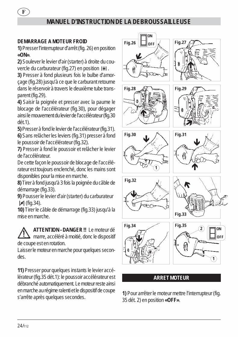
DEMARRAGE A MOTEUR FROID1) Presser l’interrupteur d’arrêt (fig. 26) en position«ON».2) Soulever le levier d’air (starter) à droite du cou-vercle du carburateur (fig.27) en position .3) Presser à fond plusieurs fois le bulbe d’amor-çage (fig.28) jusqu’à ce que le carburant retournedans le réservoir à travers le deuxième tube trans-parent (fig.29).4) Saisir la poignée et presser avec la paume leblocage de l’accélérateur (fig.30), pour dégagerainsi le mouvement du levier de l’accélérateur (fig.30dét.1).5) Presser à fond le levier de l’accélérateur (fig.31).6) Sans relâcher les leviers (fig.31) presser à fondle poussoir de l’accélérateur (fig.32).7) Presser à fond le poussoir et relâcher le levierde l’accélérateur.De cette façon le poussoir de blocage de l’accélé-rateur est toujours enclenché, donc les mains sontdisponibles pour la mise en marche.8) Tirer à fond jusqu’à 3 fois la poignée du câble dedémarrage (fig.33).9) Pousser le levier d’air (starter) du carburateur (fig.34).10) Tirer le câble de démarrage (fig.33) jusqu’à lamise en marche.
ATTENTION - DANGER !! Le moteur démarre, accéléré à moitié, donc le dispositif
de coupe est en rotation.Laisser le moteur en marche pour quelques secon-des.
11) Presser pour quelques instants le levier accé-lérateur (fig.35 dét.1): le poussoir accélérateur estdébranché automatiquement. Le moteur reste ainsien marche au régime ralenti et le dispositif de coupes’arrête après quelques secondes.
Fig.27
Fig.28 Fig.29
Fig.30 Fig.31
Fig.32
Fig.33
Fig.34 Fig.35
�
�
�
�
�
�
� �
�
1
2
1
Fig.26
�
ON
OFF
ON
OFF
ARRET MOTEUR
1) Pour arrêter le moteur mettre l’interrupteur (fig.35 dét. 2) en position «OFF».

25/112
F
MANUEL D'INSTRUCTION DE LA DEBROUSSAILLEUSE
ATTENTION! le dispositif de coupe continue à tourner pour quelques instants même
après la mise de l’interrupteur en position «OFF».Tenir solidement les deux poignées jusqu’à l’arrêtcomplet.
DEMARRAGE A MOTEUR CHAUDAppliquer la même procédure du moteur froid, maisavec le levier d’air (starter) baissé (voir fig.18).
7. UTILISATIONUTILISATION DE LA TONDEUSE1) Accrocher la courroie d’élingage (fig.36 dét.1) àla bague (fig.36 dét.2).2) Tenir l’appareil du côté droit selon les indicationsde la fig.37-38.
REGLAGE DE LA LONGUEUR DU FIL DECOUPELa tête à fils fournie avec l’appareil est du type àréglage manuel.Avant l’usure du fil de coupe jusqu’à moitié de salongueur, tirer et tourner la bobine (fig.39) pourrétablir cette longueur.Si la quantité de fil extrait était excessive, sa lon-gueur est réglée automatiquement par la lame spé-ciale pendant la rotation.
TONTE DU GAZONAvec la tête de coupe parallèle au sol, avancer pardes oscillations à droite et à gauche (fig.40).Tenir le moteur au régime de pointe pour effectuerune coupe nette.
COUPE AUTOUR D’OBSTACLES, DE PLAN-TES, D’ENCEINTESEffleurer l’obstacle avec l’extrémité du fil (fig.40).L’inclinaison de la tête (fig.41) peut améliorer la per-formance de coupe. Ne pas heurter les obstacles
avec la tête de coupe pour éviter des ruptures net-tes des fils.En cas de rupture des fils appliquer la même procé-dure du remplacement.
8. REMPLACEMENT DU FILPour enrouler un fil neuf sur la bobine originale:A) Utiliser un fil diamètre 2 mm en plastique spécialpour Debroussailleuse.
ATTENTION DANGER! NE JAMAIS UTI-LISER LE FIL EN METAL. EFFECTUERL’OPERATION MOTEUR ARRETE
B) DEMONTAGE BOBINE1) Dévisser l’écrou à ailettes dans le sens desaiguilles d’une montre (fig.42).2) Extraire la bobine (fig.43-44-45).3) Nettoyer soigneusement la partie à l’intérieur ducorps (fig.46) .
C) ENROULEMENT DU FIL1) Préparer deux bouts de fil non supérieurs à 6 m.2) Introduire l’extrémité des deux fils dans les 2orifices spéciaux (fig.47).3) Enrouler les deux bouts de fil accouplés sur labobine, suivant la direction de la flèche impriméesur la même bobine (fig.48).4) Pour faciliter la réintroduction de la bobine dansle corps, fixer les deux bouts de fil dans les deuxrainures prévues à cet effet (fig.49).
D) REMONTAGE BOBINE1) Introduire les deux bouts par les guide-fil (fig.50).2) Introduire la bobine et tirer avec force les deuxbouts de fil pour les extraire des rainures (fig.51).3) Remonter le ressort (fig.52) et serrer à nouveaul’écrou à ailettes dans le sens contraire aux aiguillesd’une montre (fig.53).

26/112
MANUEL D'INSTRUCTION DE LA DEBROUSSAILLEUSE
F
9. ENTRETIENBOUGIEAu moins une fois par an ou en cas de difficultédans le démarrage, vérifier l’état de la bougie d’al-lumage. Attendre le refroidissement du moteur avantl’opération.1) Extraire le capuchon et dévisser la bougie par laclé fournie (fig.54).En cas d’incrustations et d’usure excessive des élec-trodes, remplacer la bougie par une autre de typeéquivalent (fig.55-56).Un excès d’incrustations peut être provoqué par# Pourcentage d’huile excessif dans le carburant et/ou qualité de l’huile non appropriée.# Obstruction partielle du filtre à air2) Visser manuellement la bougie à fond pour nepas endommager son logement. Utiliser la clé spé-ciale seulement pour le serrage (fig.54).
FILTRE A AIRNettoyer périodiquement le filtre à air et souventapres des opérations dans des zones poussiéreu-ses.1) Dévisser l’écrou à ailettes du couvercle (fig.57).2) Nettoyer avec de l’eau et du détergent neutre.3) Laisser sécher le filtre avant son remontage(fig.58).Remplacer un filtre endommagé pour ne pascompromettre la durée du moteur.
FILTRE DU TUYAU D’ASPIRATION DU CAR-BURANTRemplacer une fois par an le filtre après son ex-traction par un crochet à travers l’ouverture de ra-vitaillement du réservoir.
FILET METALLIQUE PARE-ETINCELLES DUSILENCIEUX# Dans l’orifice d’échappement du gaz se trouveune bague à filet (partie plus saillante).
# A cause des dépôts l’obstruction du filet entraîneune réduction considérable des performances dumoteur.# Extraire la bague à filet par une pince à becs(fig.59).
REGIME DE RALENTI DU MOTEUR# S’assurer à chaque utilisation que le dispositif de coupe ne tourne pas au ralenti.# En cas de rotation du dispositif de coupe
s’adresser à un service après-vente pour son ré-glage.
CONTROLE VIS ET PARTIES ROTATIVES# Avant chaque utilisation vérifier le serrage correctdes vis et des parties de la machine, tout commel’absence de criques ou d’usures considérablesdans le dispositif de coupe.# Remplacer les parties endommagées avant l’utili-sation.
NETTOYAGE ET REMISAGE# Si la machine n’est pas utilisée pendant plus de 2mois, vidanger le réservoir du carburant.# Ne pas nettoyer avec des liquides agressifs.# Garder l’appareil dans un milieu sec et sûr, horsde portée des enfants.# Au moment du transport vidanger le réservoir àcarburant et protéger la lame (si elle est installée)par une protection spéciale.

27/112
F
MANUEL D'INSTRUCTION DE LA DEBROUSSAILLEUSEDONNEES TECHNIQUES GBL 26
Masse 4,8 kg (sans carburant – dispositif de coupe – protection)
Capacité réservoir 700 cm3
Dispositif de coupe (tête à fils) 420 mm Dispositif de coupe (lame) 230 mm Cylindrée moteur 25,5 cm3
Puissance maximum 0,75 KW Régime maximum du moteur 9.500 1/min. Régime maximum du dispositif de coupe 7.500 1/min Régime minimum 2.800 1/min. Niveau de pression acoustique 98 dB (A)
LpA av (EN 7917) Niveau de pression acoustique 108 dB (A)
LwA av (ISO 19884) Niveau vibrations max [fil nylon] 9,9 m/s2
(ISO 7916) Niveau vibrations max . [lame] 10,6 m/s2
(ISO 7916)
DONNEES TECHNIQUES GB 26
Masse 4,9 kg (sans carburant – dispositif de coupe – protection)
Capacité réservoir 700 cm3
Dispositif de coupe (tête à fils) 420 mm Dispositif de coupe (lame) 230 mm Cylindrée moteur 25,5 cm3
Puissance maximum 0,75 KW Régime maximum du moteur 9.500 1/min. Régime maximum du dispositif de coupe 7.500 1/min Régime minimum 2.800 1/min. Niveau de pression acoustique 98 dB (A)
LpA av (EN 7917) Niveau de pression acoustique 108 dB (A)
LwA av (ISO 19884) Niveau vibrations max [fil nylon] 9,6 m/s2
(ISO 7916) Niveau vibrations max . [lame] 10,4 m/s2
(ISO 7916)
DONNEES TECHNIQUES GBL 34
Masse 5,9 kg (sans carburant – dispositif de coupe – protection)
Capacité réservoir 830 cm3
Dispositif de coupe (tête à fils) 420 mm Dispositif de coupe (lame) 230 mm Cylindrée moteur 33,6 cm3
Puissance maximum 1 KW Régime maximum du moteur 9.500 1/min. Régime maximum du dispositif de coupe 7.500 1/min Régime minimum 2.800 1/min. Niveau de pression acoustique 97 dB (A)
LpA av (EN 7917) Niveau de pression acoustique 107 dB (A)
LwA av (ISO 19884) Niveau vibrations max [fil nylon] 8 m/s2
(ISO 7916) Niveau vibrations max . [lame] 8,9 m/s2
(ISO 7916)
DONNEES TECHNIQUES GB 34
Masse 6,0 kg (sans carburant – dispositif de coupe – protection)
Capacité réservoir 830 cm3
Dispositif de coupe (tête à fils) 420 mm Dispositif de coupe (lame) 230 mm Cylindrée moteur 33,6 cm3
Puissance maximum 1 KW Régime maximum du moteur 9.500 1/min. Régime maximum du dispositif de coupe 7.500 1/min Régime minimum 2.800 1/min. Niveau de pression acoustique 97 dB (A)
LpA av (EN 7917) Niveau de pression acoustique 107 dB (A)
LwA av (ISO 19884) Niveau vibrations max [fil nylon] 5,6 m/s2
(ISO 7916) Niveau vibrations max . [lame] 6,2 m/s2
(ISO 7916)

28/112
BEDIENUNGSANWEISUNGEN ZUM FREISCHNEIDER
D
1. AN UNSERE KUNDENWir möchten uns für Ihre Kaufentscheidungbedanken. Bei der Herstellung unseresFREISCHNEIDER haben wir zuIhrem persönlichen Schutz die geltendenSicherheitsnormen angewandt.
Diese Anleitung macht Sie mit der Montage, demAnschluß sowie der Benutzung und Wartung IhresFREISCHNEIDER vertraut, damitSie seine Vorzüge auf lange Zeit genießen können.
FÜR EIN BESSERES VERSTÄNDNISAlle Abbildungen zur Montagebefinden sich in der
Deckblattumschlagklappe.Diese während des Durchlesens derMontageanleitungen aufschlagen.
Bei Kundendienstleistungen und Reparaturenwenden Sie sich bitte an Ihren Händler bzw. aneine autorisierte Servicestelle..
2. WESENTLICHESICHERHEITSVORKEHRUNGEN
ALLGEMEINE NORMEN
HINWEISE:A1 – Die Anwendung des FREI-SCHNEIDER erfordert die Einhaltungder Sicherheitsnormen.A2 – Alle Benützer des FREI-SCHNEIDER müssen zuerst dieBedienungs- und Wartungsanleitungaufmerksam durchlesen und sich mit denSteuerungen für einen richtigen Betriebdes Geräts vertraut machen.A2.1 - Dieses Handbuch zum späte-ren Nachschlagen aufbewahren.
A3 – Kindern und Personen, die diehier stehenden Anweisungen nicht ken-nen, ist die Anwendung des FREI-SCHNEIDER untersagt.
GEFAHR:A4 – Auf das von der Schnittvorrichtungprojizierte Material aufpassen.A5 – In der Nähe von Personen, Tie-ren oder Gegenständen darf derRasentrimmer weder gestartet nochbenützt werden.Während des Betriebs ist ein Mindest-abstand von 15 m zwischen der Ma-schine und anderen Personen emp-fohlen.A6 – Für Verletzungen an anderenPersonen oder Gegenständen oder fürGefahren haftet der Bediener.
ANWENDUNG:B1 – Das FREISCHNEIDER nur zumSchneiden von Gras, Kräutern undSträuchern verwenden.Das Gerät darf nicht für andere Zwek-ke angewendet werden.B2 – Eine für die Anwendung des FREI-SCHNEIDER passende Kleidung undSchutzausrüstung tragen.Während der Benützung ist anliegen-de und keine lose Kleidung zu tragen.B3 – Zugelassene Schutzbrillen oderVisiere tragen.B3.1 – Zugelassenen Ohrenschutzgegen Lärm tragen.B3.2 – Besteht die Gefahr fallenderGegenstände ist ein Schutzhelm aufzu-setzen.B4 – Widerstandsfähige Schuhe mitrutschfesten Sohlen tragen.B5 – Widerstandsfähige Handschuhetragen.B6 – Die Benützer des FREI-SCHNEIDER müssen körperlich gut in

29/112
D
BEDIENUNGSANWEISUNGEN ZUM FREISCHNEIDER
Form sein. Bei Müdigkeit, Übelkeit undunter Einfluß von Alkohol oder ande-ren Drogen darf der FREI-SCHNEIDER nicht benützt werden.
B7 - ACHTUNG Die Abgase sind giftigund wirken erstickend. Bei Einatmenkönnen sie auch tödliche Auswirkun-gen haben. Der Motor darf in geschlos-senen oder wenig belüfteten Räumennicht in Betrieb genommen werden.B8 – Die verlängerte Anwendung desGeräts kann Durchblutungsstörungenin den Händen verursachen (Weiße-Finger-Krankheit), die auf dieVibrationen zurückzuführen sind.Folgende können die Faktoren sein,die das Erscheinen der Störungen be-einflussen:- Persönliche Neigung desBedieners zur schwachenDurchblutung der Hände.- Anwendung des Geräts beiniedrigen Temperaturen (daherwerden warme Handschuheempfohlen).- Lange Anwendungszeit ohneUnterbrechungen (die Anwendung mitEinlegen von Pausen ist empfohlen).- Bei Verspüren von Kribbeln undGefühllosigkeit wird das Aufsucheneines Arztes empfohlen.B8.1 – Das Gerät immer mit beidenHänden halten.Mit den Beinen eine feste und sicherePosition einnehmen.B8.2 – Der FREISCHNEIDER ist soausgelegt, um vom Bediener auf derrechten Seite verwendet zu werden(siehe Abb. 37-38).Den hinteren Griff (mit Steuerungen)mit der rechten Hand und den Vorder-
griff mit der linken Hand festhalten.B9 - ACHTUNG! Das Benzin und sei-ne Dämpfe sind leichtentzündlich.BRANDWUNDEN- UND BRANDGE-FAHR.B9.1 – Den Motor vor dem Nachtan-ken abstellen.B9.2 – Während dem Auftanken nichtrauchen.B9.3 – Den eventuell verschüttetenTreibstoff trocknen. Den Motor an ei-nem von der Auftankstelle entfernten Ortstarten.B9.4 – Sich vergewissern, dass derDeckel des Tankbehälters gut ver-schlossen ist. Auf eventuelle Leckstellenachten.B10 – Mit dem Gerät wird eineSCHUTZABDECKUNG DERSCHNITTVORRICHTUNG (Abb.1Det.21) geliefert, die vor der Anwen-dung montiert werden muß (sieheMontageanleitung).Ohne dieser Schutzabdeckung darf dasGerät weder gestartet noch verwendetwerden.B10.1 - GEFAHR! Durch die Schnitt-vorrichtung verursachte Wunden; Pro-jizieren von Material auf den Bediener.Die Schutzabdeckung nicht abändern.Eine schadhafte Schutzabdeckung darfnur mit einem Original-Ersatzteil aus-getauscht werden.B10.2 – GEFAHR! Keinen Draht in denSchnittkopf montieren.B10.3 – Die BLOCKIERVOR-RICHTUNG DER GASHEBELS-TEUERUNG (siehe Abb. 1 Det. 16):verhindert einen unabsichtlichen An-trieb des Gashebels.B10.4 - SCHALTER (ON/OFF) zumAbstellen des Motors (Abb.1 Det.14).

30/112
BEDIENUNGSANWEISUNGEN ZUM FREISCHNEIDER
D
GEFAHR! Achtung! Die Schnittvor-richtung dreht sich noch für eine ge-wisse Zeit nach dem Ausschalten(Schalter auf Position “OFF”) weiter. Diezwei Griffe bis zum vollständigen Still-stand festhalten. Siehe Kapitel ANLAUFUND STOP.B10.5 GEFAHR! Keine Sägeblätteranbauen.B10.6 GEFAHR! Keine mehrteiligenKlingen, sondern nur fugenloseKlingen anbauen.B10.7 GEFAHR! Keine Klingen mitDurchmesser größer als 230 mmanbauen.
3. BESCHREIBUNG DERMASCHINENTEILE
BESCHREIBUNG ABB.11) Griff des Anlasserseils2) Anlasser3) Startlufthebel4) Zündkerzenkappe5) Tankverschluss6) Schalldämpfer7) Linkshandgriff (Handstange)8) Explosionsmotor9) Kraftstoffstank10) Rechtshandgriff mit Steuerungen (Hand-
stange)11) Hinterhandgriff Steuerungen12) Riemeneinsatzpunkt13) Vorderhandgriff14) Motorabstellvorrichtung ON/OFF.15) Halbtouren-Knopfblockierung16) Gashebelsteuerungsperre17) Gashebel18) Übertragungsrohr (Stange)19) Klinge20) Schutz für die Schnittvorrichtung
(Klingenschutz)21) Schutz für die Schnittvorrichtung (Faden
kopfschutz)22) Schneidwerkzeug (Fadenkopf)23) Schlinge mit Traggurt24) Sperre
4. MONTAGEVORDERHANDGRIFF ZUM MODELL GBL26/341) Handgriff (Det.1) und Sperre (Det.2) gemäß Abb.2 positionieren.2) Die 4 Schrauben, Scheiben und Mutterfestspannen (Abb.3)Die Sperre dient dazu, einenSicherheitsabstand zwischen dem Benützerund dem Scheidwerkzeug zu gewährleisten.
HANDSTANGE MIT HANDGRIFF ZUM MODELLGB 26/341) Das FREISCHNEIDER wird mitzusammengelegter Handstange verpackt (Abb. 4).2) Kugelgriff lösen (Abb.5) und Handstange querdrehen.3) Durch Festziehen des Kugelgriffs fest dieHandstange blockieren (Abb.6).Die Handstange kann zum Transport- oderInstandsetzungszwecken zusammengelegt sowie füreine bequemere Arbeitsposition eingestellt werden.
Die FREISCHNEIDER GB26/34, GBL26/34können verwendet werden:A. zum Freischneiden mit angebauter Klinge undKlingenschutz (Abb.1 Det. 19-20)B. zum Grasschneiden mit angebautem Fadenkopfund Erstreckungsstück (Abb.1 Det. 21-22), der aufden Schutz selbst angeschraubt wird.
ACHTUNG! Die von den gü l t igenN o r m e n v o r g e s e h e n e nSicherheitsbedingungen treten nur
beim Anbauen der Schutzvorrichtungen, wieoben beschrieben, ein.
31/112
D
BEDIENUNGSANWEISUNGEN ZUM FREISCHNEIDER
KLINGENANBAU UND SCHUTZ (Abb.7-8)
ACHTUNG! Für alle Montage- undWartungseingriffe auf der Klingei m m e r d i e S c h u t z h a n d s c h u h eanziehen.
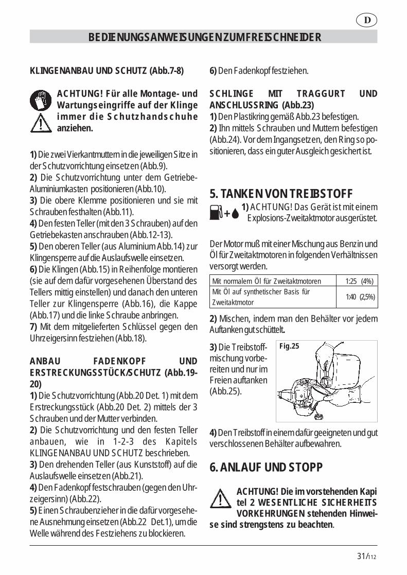
1) Die zwei Vierkantmuttern in die jeweiligen Sitze inder Schutzvorrichtung einsetzen (Abb.9).2) Die Schutzvorrichtung unter dem Getriebe-Aluminiumkasten positionieren (Abb.10).3) Die obere Klemme positionieren und sie mitSchrauben festhalten (Abb.11).4) Den festen Teller (mit den 3 Schrauben) auf denGetriebekasten anschrauben (Abb.12-13).5) Den oberen Teller (aus Aluminium Abb.14) zurKlingensperre auf die Auslaufswelle einsetzen.6) Die Klingen (Abb.15) in Reihenfolge montieren(sie auf dem dafür vorgesehenen Überstand desTellers mittig einstellen) und danach den unterenTeller zur Klingensperre (Abb.16), die Kappe(Abb.17) und die linke Schraube anbringen.7) Mit dem mitgelieferten Schlüssel gegen denUhrzeigersinn festziehen (Abb.18).
ANBAU FADENKOPF UNDERSTRECKUNGSSTÜCK/SCHUTZ (Abb.19-20)1) Die Schutzvorrichtung (Abb.20 Det. 1) mit demErstreckungsstück (Abb.20 Det. 2) mittels der 3Schrauben und der Mutter verbinden.2) Die Schutzvorrichtung und den festen Telleranbauen, wie in 1-2-3 des KapitelsKLINGENANBAU UND SCHUTZ beschrieben.3) Den drehenden Teller (aus Kunststoff) auf dieAuslaufswelle einsetzen (Abb.21).4) Den Fadenkopf festschrauben (gegen den Uhr-zeigersinn) (Abb.22).5) Einen Schraubenzieher in die dafür vorgesehe-ne Ausnehmung einsetzen (Abb.22 Det.1), um dieWelle während des Festziehens zu blockieren.
6) Den Fadenkopf festziehen.
SCHLINGE MIT TRAGGURT UNDANSCHLUSSRING (Abb.23)1) Den Plastikring gemäß Abb.23 befestigen.2) Ihn mittels Schrauben und Muttern befestigen(Abb.24). Vor dem Ingangsetzen, den Ring so po-sitionieren, dass ein guter Ausgleich gesichert ist.
5. TANKEN VON TREIBSTOFF 1) ACHTUNG! Das Gerät ist mit einem Explosions-Zweitaktmotor ausgerüstet.
Der Motor muß mit einer Mischung aus Benzin undÖl für Zweitaktmotoren in folgenden Verhältnissenversorgt werden.
2) Mischen, indem man den Behälter vor jedemAuftanken gut schüttelt.
1:40 (2,5%)
Mit normalem Öl für Zweitaktmotoren 1:25 (4%) Mit Öl auf synthetischer Basis für Zweitaktmotor
3) Die Treibstoff-mischung vorbe-reiten und nur imFreien auftanken(Abb.25).
4) Den Treibstoff in einem dafür geeigneten und gutverschlossenen Behälter aufbewahren.
6. ANLAUF UND STOPP
ACHTUNG! Die im vorstehenden Kapitel 2 WESENTLICHE SICHERHEITSVORKEHRUNGEN stehenden Hinwei-
se sind strengstens zu beachten.
Fig.25

32/112
BEDIENUNGSANWEISUNGEN ZUM FREISCHNEIDER
D
ANLAUF BEI KALTEM MOTOR1) Den Stoppschalter (Abb.26) auf die Position „ON“drücken.2) Den neben dem Treibstoffdeckel (Abb. 27) rechtsangeordneten Lufthebel heben und ihn in die Posi-tion bringen.3) Den Primerwulstknopf (Abb.28) wiederholt tiefdrücken, bis der Treibstoff über den zweitentransparenten Schlauch in den Behälterzurückkehrt(Abb.29).4) Den Griff nehmen und mit der Handfläche dieBlockiervorrichtung des Gashebels (Abb.30)drücken, wodurch der Gashebel freigängiggemacht wird. (Abb.30 Det.1).5) Den Gashebel tief drücken (Abb.31).6) Bei gedrückten Hebeln (Abb.31) den HalbtourenKnopf (Abb. 32) tief drücken.7) Den Knopf gedrückt halten und den Gashebelloslassen. Auf diese Weise bleibt der Halbtouren-Blockierknopf gedrückt und die Hände bleiben so-mit frei für den Anlauf.8) Den Startseilgriff (Abb. 33) bis zu 3 Mal vollstän-dig ziehen.9) Den kleinen Vergaserlufthebel nach unten drük-ken (Abb.34).10) Das Startseil (Abb.33) bis zur Inbetriebnahmeziehen.
ACHTUNG - GEFAHR !! Der Motor startet und bleibt halb beschleunigt und somit
mit rotierender Schnittvorrichtung.Den Motor für einige Sekunden funktionieren las-sen.
11) Durch kurzes Drücken des Gashebels (Abb.35 Det.1) wird der Halbtouren-Knopf automatischausgeschaltet. Der Motor bleibt auf diese Weise aufMindesttouren in Betrieb und die Schnittvorrichtungbleibt nach kurzer Zeit stehen.
Fig.27
Fig.28 Fig.29
Fig.30 Fig.31
Fig.32
Fig.33
Fig.34 Fig.35
�
�
�
�
�
�
� �
�
1
2
1
Fig.26
�
ON
OFF
ON
OFF
MOTOR-STOPP
1) Zum Stoppen des Motors ist der Schalter (Abb.35 Det. 2) in die Position „OFF“ zu stellen.

33/112
D
BEDIENUNGSANWEISUNGEN ZUM FREISCHNEIDER
ACHTUNG ! Die Schnittvorrichtung drehtsich noch für eine gewisse Zeit nach dem
Ausschalten (Schalter auf Position “OFF”) weiter.Die zwei Griffe bis zum vollständigen Stillstand fest-halten
ANLAUF MIT WARMEM MOTORDerselbe Vorgang wie beim kalten Motor, aber denLufthebel nach unten senken (siehe Abb.34).
7. ANWENDUNGANWENDUNG DES RASENTRIMMERS1) Die Schlinge mit Traggurt (Abb.36 Det.1) in denRing einhaken (Abb.36 Det.2).2) Das Gerät entsprechend der Abb. 37-38 auf derrechten Seite halten.
EINSTELUNG DER SCHNITTFADENLÄNGEDer zur Ausrüstung gehörende Fadenkopf ist hand-einstellbar.Bevor sich der Schnittfaden bis zu seiner halbenLänge abnützt, ist die Länge neu einzustellen, in-dem die Spule zu ziehen und danach zu drehen ist(Abb.39).Sollte die herausgezogene Fadenlänge zu lang sein,wird diese durch die speziell dafür vorgeseheneKlinge während der Rotation automatisch einge-stellt.
SCHNEIDEN VON GRASDen Schnittkopf parallel zum Boden halten, vor-wärtsgehen und dabei nach rechts und links schwin-gen (Abb. 40). Den Motor auf vollen Touren, umeinen reinen Schnitt zu erzielen.
HINDERNISSE, PFLANZEN, ZÄUNE UM-SCHNEIDENDas Hindernis mit dem Fadenende (Abb. 40) strei-fen. Durch Neigen des Kopfs (Abb. 41) kann dieSchnittwirkung verbessert werden. Damit die Fä-den nicht kaputt gehen, darf mit dem Schnittkopf an
den Hindernissen nicht angestoßen werden. Reißtein Faden, ist dieser gemäß der Beschreibung fürden Wechsel des Fadens zu ersetzen.
8. FADENWECHSELAufwickeln eines neuen Fadens auf die Originals-pule:A) Verwenden Sie einen Faden mit Durchmesser 2mm aus Kunststoff, speziell für Rasentrimmer mitFaden.
ACHTUNG GEFAHR! IN KEINEM FALLDRAHT VERWENDEN. DEN VORGANG BEI AUSGESCHALTETEM MOTOR AUSFÜHREN.
B) AUSBAU DER SPULE1) Flügelmutter im Uhrzeigersinn abschrauben(Abb.42).2) Spule ausziehen (Abb.43-44-45).3) Den Körper innen sorgfältig reinigen (Abb.46) .
C) FADENUMWICKLUNG1) Zwei nicht länger als 6 m lange Fäden vorberei-ten.2) Die Enden der beiden Fäden in die entspre-chenden 2 Löcher einführen (Abb.47).3) Die zwei verbundenen Fadenlängen auf dieSpule wickeln und die auf der Spule eingeprägtePfeilrichtung beachten (Abb.48).4) Um die Wiedereinführung der Spule in den Kör-per zu erleichtern, die beiden Fadenenden in denbeiden dafür vorgesehenen Schlitzen befestigen(Abb.49).
D) WIEDEREINBAU DER SPULE1) Die zwei Enden durch den Fadendurchgangführen (Abb.50).2) Die Spule einführen und die Fadenenden festziehen, damit sie sich von den Schlitzen abziehen(Abb.51).

34/112
BEDIENUNGSANWEISUNGEN ZUM FREISCHNEIDER
D
3) Die Feder (Abb.52) wieder positionieren unddie Flügelmutter gegen den Uhrzeigersinn wiederanschrauben (Abb.53).
9. WARTUNGKERZEMindestens einmal jährlich oder bei Störungen wäh-rend des Startens ist der Zustand der Zündkerzezu überprüfen. Abwarten, bis der Motor kalt ist.1) Die Zündkerzenkappe abziehen und die Kerze mitdem mitgelieferten Schlüssel abschrauben (Abb. 54).Bei übermäßigen Verkrustungen und beachtlichemVerschleiß der Elektroden ist die Kerze mit einergleichwertigen zu ersetzen (Abb.55-56).Übermäßige Verkrustungen können bedingt sein durch:# Der Ölanteil im Treibstoff ist zu hoch bzw. dieÖlqualität ist nicht optimal.# Luftfilter teilweise verstopft.2) Die Kerze mit der Hand komplett ins Gewindeanschrauben, um Schäden am Kerzensitz zu ver-meiden; der entsprechende Schlüssel ist nur zumFestziehen (Abb. 54) zu verwenden.
LUFTFILTERDer Luftfilter ist regelmäßig zu reinigen; eine häufi-gere Reinigung ist angebracht, wenn man in stau-biger Umgebung arbeitet.1) Die Flügelschraube des Deckels abschrauben(Abb.57).2) Mit Wasser und neutralem Reinigungsmittel reinigen.3) Den Filter trocknen lassen, bevor er wiederplatziert wird.(Abb.58).Ein beschädigter Filter muß ersetzt werden,um die Lebensdauer des Motors nicht zu ver-kürzen.
TREIBSTOFF-FANGFILTEREinmal jährlich den Filter ersetzen; den Filter miteinem Haken über die Treibstoffversorgungs-öffnung herausziehen.
FUNKENSIEB DES SCHALLDÄMPFERS# In der Gasablassöffnung ist ein Ring mit Sieb(herausragendster Teil) eingefügt.# Auf Grund der Ablagerungen besteht die Gefahr,dass sich das Sieb verstopft und somit die Motorlei-stung erheblich reduziert.# Den Ring mit Sieb mit einer spitzen Zange her-ausziehen (Abb.59).
MINDESTDREHZAHL DES MOTORS# Bei jeder Anwendung sich davon überzeugen, dass sich die Schnittvorrichtung imMindestdrehzahlbereich nicht dreht.
# Sollte die Schnittvorrichtung zur Rotation neigen,wenden Sie sich für die entsprechende Einstellungan einen Kundendienst.
ÜBERPRÜFUNG DER SCHRAUBEN UND DERDREHENDEN TEILE# Vor jeder Anwendung sich davon überzeugen,dass keine losen Schrauben oder Teile bzw. Risseoder starke Abnützungen auf der Schnittvorrichtungvorhanden sind.# Bevor Sie das Gerät benützen sind die schadhaf-ten Teile zu ersetzen.
REINIGUNG UND LAGERUNG# Wird das Gerät für länger als 2 Monate nicht ver-wendet, muß der Treibstoffbehälter entleert werden.# Keine aggressiven Reinigungsmittel verwenden.# Das Gerät ist auf einer trockenen und sicheren,Kindern unzugänglichen Stelle zu lagern.# Beim Transport den Treibstofftank ausleeren unddie Klinge (wenn angebaut) mittels einer dazu ge-eigneten Schutzvorrichtung schützen.

35/112
D
BEDIENUNGSANWEISUNGEN ZUM FREISCHNEIDER
TECHNISCHE DATEN GBL 26
Gewicht 4,8 kg (ohne Treibstoff – Schnittvorrichtung – Schutz)
Behältervolumen 700 cm3
Schnittvorrichtung (Fadenkopf) 420 mm Schnittvorrichtung (Klinge) 230 mm Motorhubraum 25,5 cm3
Höchstleistung 0,75 KW Max. Motortouren 9.500 1/min Max. Touren von der Schnittvvorrichtung 7.500 1/min Mindesttouren 2.800 Schalldruckpegel 98 dB(A) LpA av (EN 7917) Schalleistungspegel 108 dB(A) LwA av (ISO 10884) Max. Vibrationspegel 9,9 m/s2
(ISO 7916) Max. Vibrationspegel der Klinge 10,6 m/s2
(ISO 7916)
TECHNISCHE DATEN GB 26
Gewicht 4,9 kg (ohne Treibstoff – Schnittvorrichtung – Schutz)
Behältervolumen 700 cm3
Schnittvorrichtung (Fadenkopf) 420 mm Schnittvorrichtung (Klinge) 230 mm Motorhubraum 25,5 cm3
Höchstleistung 0,75 KW Max. Motortouren 9.500 1/min Max. Touren von der Schnittvvorrichtung 7.500 1/min Mindesttouren 2.800 Schalldruckpegel 98 dB(A) LpA av (EN 7917) Schalleistungspegel 108 dB(A) LwA av (ISO 10884) Max. Vibrationspegel 9,6 m/s2
(ISO 7916) Max. Vibrationspegel der Klinge 10,4 m/s2
(ISO 7916)
TECHNISCHE DATEN GBL 34
Gewicht 5,9 kg (ohne Treibstoff – Schnittvorrichtung – Schutz)
Behältervolumen 830 cm3
Schnittvorrichtung (Fadenkopf) 420 mm Schnittvorrichtung (Klinge) 230 mm Motorhubraum 33,6 cm3
Höchstleistung 1 KW Max. Motortouren 9.500 1/min Max. Touren von der Schnittvvorrichtung 7.500 1/min Mindesttouren 2.800 1/min Schalldruckpegel 97 dB(A) LpA av (EN 7917) Schalleistungspegel 107 dB(A) LwA av (ISO 10884) Max. Vibrationspegel 8 m/s2
(ISO 7916) Max. Vibrationspegel der Klinge 8,9 m/s2
(ISO 7916)
TECHNISCHE DATEN GB 34
Gewicht 6,0 kg (ohne Treibstoff – Schnittvorrichtung – Schutz)
Behältervolumen 830 cm3
Schnittvorrichtung (Fadenkopf) 420 mm Schnittvorrichtung (Klinge) 230 mm Motorhubraum 33,6 cm3
Höchstleistung 1 KW Max. Motortouren 9.500 1/min Max. Touren von der Schnittvvorrichtung 7.500 1/min Mindesttouren 2.800 1/min Schalldruckpegel 97 dB(A) LpA av (EN 7917) Schalleistungspegel 107 dB(A) LwA av (ISO 10884) Max. Vibrationspegel 5,6 m/s2
(ISO 7916) Max. Vibrationspegel der Klinge 6,2 m/s2
(ISO 7916)

36/112
GEBRUIKSAANWIJZING VAN DE STRUIKENSNOEIER
NL
1. GEFELICITEERDBeste klant, wij feliciteren u met uw keuze van éénvan onze producten voor de tuin. DeSTRUIKENSNOEIERS isgebouwd volgens de geldende veiligheidsnormenter bescherming van de consument.
In dit instructieboekje worden de verschillendehandelingen voor montage, installatie en gebruikbeschreven en geï l lustreerd, evenals deonderhoudswerkzaamheden die nodig zijn om uwSTRUIKENSNOEIERS in perfecte staat vanwerking te houden.
VOOR EEN BETER BEGRIPAfbeeldingen voor de montage zijnte zien op achterzijde van de
omslag aan het begin van dit boekje. Laat dezepagina ’s tijdens het lezen van demontageaanwijzingen open liggen.
Voor eventuele service of reparatie van uwSTRUIKENSNOEIERS dient u zich tot uwwinkelier of tot een erkend servicecentrum tewenden.
2. FUNDAMENTELEVEILIGHEIDSMAATREGELEN
ALGEMENE NORMEN
WAARSCHUWINGEN:A1 - Neem, bij het gebruik van deSTRUIKENSNOEIERS deveiligheidsnormen in acht.A2 - Lees eerst zorgvuldig dehandleiding voor gebruik enonderhoud om geheel vertrouwd teraken met de bedieningselementen, ditten behoeve van een correct gebruik
van het apparaat.A2.1 - Bewaar deze handleiding voortoekomstige raadpleging.A3 - Sta het gebruik van deSTRUIKENSNOEIERS niet toe aankinderen en personen, die niet geheelop de hoogte zijn van deze instructies.
GEVAAR:A4 - Wees bedacht op materiaal dat uitde maai-inrichting wegschiet.A5 - Stel de grasmaaier niet in werkingen gebruik deze niet in de nabijheidvan mensen, dieren of voorwerpen.Tijdens de werking wordt hetaanbevolen een minimumafstand van15 m. aan te houden tussen degebruiker en andere personen.A6 - De gebruiker is aansprakelijk bijongelukken, gevaar voor anderen, ofschade aan bezittingen van anderen.GEBRUIK:B1 – Gebruik deSTRUIKENSNOEIER alleen voor hetmaaien van gras, onkruid en struiken.Gebruik het apparaat niet voor anderedoeleinden, dus niet voor andere doel-einden.B2 - Draag kleding en eenveiligheidsuitrusting die geschikt is voorhet gebruik van deSTRUIKENSNOEIER.Draag tijdens het gebruiknauwsluitende, niet loshangendekleding.B3 - Draag een goedgekeurdeveiligheidsbril of een gezichtsmasker.B3.1 - Draag goedgekeurdeoorbescherming tegen het lawaai.B3.2 - Draag een veiligheidshelm bijrisico op vallende voorwerpen.
37/112
NL
GEBRUIKSAANWIJZING VAN DE STRUIKENSNOEIER
B4 - Draag stevige werkschoenen metanti-slipzolen.B5 - Draag stevige handschoenen.B6 - Maak alleen gebruik van deSTRUIKENSNOEIERS als u ingoede conditie bent. GEBRUIK deSTRUIKENSNOEIERS NIETwanneer u vermoeid bent, zich nietlekker voelt of onder invloed bent vanalcohol of drugs.B7 - ATTENTIE! De uitlaatgassen zijngiftig en verstikkend. Bij inademingkunnen ze zelfs dodelijk zijn. Laat demotor niet draaien in een gesloten enschaars geventileerde ruimte.B8 - Langdurig gebruik van hetapparaat kan een verstoring van debloedsomloop in de handenveroorzaken (ziekte van de wittevingers), die toegeschreven wordt aande trillingen.Factoren die van invloed kunnen zijnop deze verschijnselen zijn:- Persoonlijke aanleg van de gebruiker:schaarse bloedtoevoer naar dehanden.- Gebruik van het apparaat bij lagetemperaturen (het gebruik van warmehandschoenen wordt aanbevolen).- Langdurig gebruik zonderonderbrekingen (het wordt aanbevolenpauzes in te lassen).- Tinteling en verstijving, hierbij wordthet aanbevolen een arts te raadplegen.B8.1 - Houd het apparaat altijd metbeide handen vast. Neem een stabieleen zekere houding aan.B8.2 - De STRUIKENSNOEIER isontworpen voor het gebruik op derechterheup van de gebruiker (zieafb.37-38).
Houd de achterste handgreep (met debedieningen) in de rechterhand en devoorste handgreep in de linkerhand.B9 - ATTENTIE! De benzine en debenzinedampen zijn uiterstontvlambaar, dus gevaar voorBRANDWONDEN- EN BRAND.B9.1 - Breng de motor tot stilstand vóórhet toevoeren van brandstof.B9.2 - Rook niet tijdens debrandstoftoevoer.B9.3 - Droog de eventueel gemorstebrandstof. Stel het apparaat in werkingop grote afstand van de plaats waar debrandstoftoevoer plaatsvond.B9.4 - Overtuig u ervan dat de dopvan de tank goed vast zit.Let op eventuele lekkages.B10 - Bij het apparaat is eenBESCHERMKAP VOOR DE MAAI-INRICHTING geleverd (Afb.1 detail21) die vóór het gebruik gemonteerdmoet worden (zie de instructies voormontage).Het apparaat niet in werking stellen,noch gebruiken indien de beschermkapniet gemonteerd is.B10.1 - GEVAAR! Letsel ten gevolgevan aanraking met de maai-inrichtingof wegschieten van materiaal in derichting van de gebruiker.Wijzig niets aan de beschermkap.Vervang de beschermkap wanneerdeze beschadigd is en gebruik hiervooralleen originelevervangingsonderdelen.B10.2 - GEVAAR! Monteer geenmetaaldraad in de maaikop.B10.3 - De BLOKKERING VAN DEBEDIENING VAN DE VERSNELLING(zie afb.1 detail 16): voorkomt de

38/112
onvrijwillige activering van de hendelvan de versnelling.B10.4 - SCHAKELAAR (ON/OFF)voor stilstand van de motor (afb. 1 detail14).GEVAAR! Attentie, de maai-inrichtingblijft gedurende een bepaalde tijddoorgaan met draaien, ook nadat deschakelaar op “OFF” gezet is. Houdde beide handgrepen stevig vast tothet apparaat geheel tot stilstand isgekomen. Zie het hoofdstuk STARTENEN STILSTAND.B10.5 GEVAAR! Geen zaagbladenmonteren.B10.6 GEVAAR! Geen bladen mon-teren die uit meerdere delen be-staan, maar alleen bladen uit éénstuk.B10.7 GEVAAR! Geen bladen mon-teren met een diameter groter dan230 mm.
3. BESCHRIJVING MACHINEDELENBESCHRIJVING Afb. 1
1) Handgreep van de startkabel2) Starter3) Luchthendeltje4) Kapje van de bougie5) Dop brandstoftank6) Geluiddemper7) Linker handgreep (stuur)8) Verbrandingsmotor9) Brandstoftank10) Rechter handgreep met bediening (stuur)11) Achterste handgreep met bediening12) Bevestigingspunt voor riem13) Voorste handgreep14) Stopinrichting van de motor ON/OFF.15) Blokkering halve versneller
16) Blokkering van de bediening van deversnellingshendel
17) Versnellingshendel18) Transmissieleiding (stang)19) Maaiblad20) Beschermkap maai-inrichting (voor maai-
blad)21) Beschermkap maai-inrichting (voor kop
met draden)22) Maai-inrichting (kop met draden)23) Draagstel met riem24) Barrière
4. MONTAGEVOORSTE HANDGREEP VOOR MODEL GBL26/341) Plaats de handgreep (detail 1) en de barrière(detail 2) zoals getoond wordt door afb. 2.2) Zet de 4 schroeven, de borgringen en de moe-ren vast (afb. 3)De barrière dient ter garantie van eenveiligheidsafstand tussen de gebruiker en demaai-inrichting.
STUUR MET HANDGREPEN VOOR MODEL GB26/341) De STRUIKENSNOEIER wordt verpakt met op-gevouwen stuur (afb. 4).2) Draai de knop losser (afb. 5) en draai het stuurdwars.3) Zet het stuur vast door de knop tot het einde toevast te draaien (afb. 6).Het stuur kan voor het gemak opgevouwen wor-den voor transport of opslag; het kan tevens inge-steld worden ten behoeve van een comfortabelewerkpositie.
De STRUIKENSNOEIERS GB26/34,GBL26/34kunnen gebruikt worden:A. Voor het snoeien van struiken door het maaibladen de beschermkap van het maaiblad te monteren
GEBRUIKSAANWIJZING VAN DE STRUIKENSNOEIER
NL

39/112
NL
GEBRUIKSAANWIJZING VAN DE STRUIKENSNOEIER
(afb.1 detail19-20).B. Voor het maaien van gras, door de kop metdraden en het verlengstuk te monteren (afb.1 de-tail 21-22), die op de beschermkap zelf wordt vast-geschroefd.
ATTENTIE! De veiligheid, die moetvoldoen aan de heersende normen,
wordt alleen bereikt wanneer de eerder be-schreven beschermkappen gemonteerd wor-den.
MONTAGE MAAIBLAD EN BESCHERMKAP(afb.7-8)
ATTENTIE! Draag ve i l ighe idshandschoenen bij alle handelingenvan montage en onderhoud van hetmaaiblad.
1) Plaats de twee vierkante moeren in de betre-fende zittingen in de beschermkap (afb. 9).2) Plaats de beschermkap onder de aluminiumtransmissiekast (afb.10).3) Plaats het bovenste klemmetje en zet het vast metde schroeven (afb.11).4) Schroef (met de drie schroeven) het vaste plaatjevast op de transmissiekast (afb.12-13).5) Steek het bovenste plaatje (van aluminium, afb.14), dat het maaiblad blokkeert, in de uittredende as.6) Monteer achtereenvolgens: het maaiblad (afb.15) (centreer het op de daarvoor bestemde uitste-kende rand van het plaatje), en het onderste plaatje(afb.16) dat het maaiblad blokkeert, het bakje(afb.17) en de linker schroef.7) Linksdraaiend vastzetten met behulp van debijgeleverde sleutel (afb.18).
MONTAGE KOP MET DRADEN EN VERLENG-STUK/BESCHERMKAP (afb.19-20)1) Verbind de beschermkap (afb. 20 detail1) met
het verlengstuk (afb. 20 detail 2) en zet het geheelvast met de 3 schroeven en de moeren.2) Monteer de beschermkap en het vaste plaatje,zoals beschreven wordt in de punten 1-2-3 van deparagraaf MONTAGE MAAIBLAD ENBESCHERMKAP.3) Breng het roterende plaatje (van plastic) aanrond de uittredende as (afb. 21).4) Schroef de kop met de draden vast (tegen dewijzers van de klok in) (afb. 22).5) Steek een schroevendraaier in de daarvoorbestemde holte (afb. 22 detail 1), om de as te blok-keren tijdens het vastzetten.6) Zet de kop met draden vast.
DRAAGSTEL MET RIEM EN BEVESTIGINGS-RING (afb. 23)1) Bevestig de plastic ring zoals getoond wordt inafb. 23.2) Zet de ring vast met de schroeven en de moeren(afb. 24). Voordat u het apparaat in werking stelt,dient u de positie van de ring te regelen ten behoevevan een goede uitbalancering.
5. BRANDSTOFTOEVOER 1) ATTENTIE! H e t a p p a r a a t i s
u i t g e r u s t m e t e e n t w e e t a k tverbrandingsmotor.
De motor moet gevoed worden met een mengselvan benzine en olie voor tweetakt motoren, waarbijde volgende percentages aangehouden moetenworden:
Gewone olie voor tweetakt motoren 1:25 (4%) Olie op synthetische basis voor tweetakt motoren 1:40 (2,5%)
2) Meng de inhoud van de houder door deze flinkte schudden vóór iedere brandstoftoevoer.

40/112
3) Bereid hetbrandstofmengselalleen in de openlucht en giet hetook daar in detank (afb. 25).
GEBRUIKSAANWIJZING VAN DE STRUIKENSNOEIER
NL
4) Bewaar de brandstof in een voor dat doelbestemde houder, die goed afgesloten wordt meteen dop.
6. STARTEN EN STILSTAND
ATTENTIE! Houdt u strikt aan de waarschuwingen die opgenomen zijn in
Hoofdstuk 2: FUNDAMENTELEVEILIGHEIDSMAATREGELEN.
STARTEN MET EEN KOUDE MOTOR1) Druk de stopschakelaar (afb. 26) in stand “ON”.2) Licht het luchthendeltje op, rechts van het dekselvan de carburateur (afb. 27), en zet het in stand .3) Druk het primerbolletje enkele malen helemaal in(afb. 28), tot de brandstof door de transparanteleiding (fig. 29) in de tank terugkeert.4) Pak de handgreep vast en druk met de handpalmop de blokkering van de versnellingshendel,waardoor de beweging hiervan gedeblokkeerdwordt (afb.30 detail 1).5) Druk de versnellingshendel helemaal in (afb.31).6) Terwijl u de hendel ingedrukt houdt (afb.31),drukt u de knop voor halve snelheid helemaal in(afb.32).7) Terwijl u deze knop ingedrukt houdt, laat u dehendel van de versnelling los.Op deze wijze blijft de blokkeerknop voor halvesnelheid ingeschakeld, en heeft u beide handenvrij voor het starten.8) Trek tot 3 keer toe de handgreep van destartkabel helemaal uit (afb. 33).
Afb.25
9) Duw het luchthendeltje van de carburateur omlaag (afb.34).10) Trek aan de startkabel (afb.33) tot de motoraanslaat.
Afb.11
Afb.12 Afb.13
Afb.14 Afb.15
Afb.16
Afb.17
Afb.18 Afb.19
�
�
�
�
�
�
� �
�
1
2
1
Afb.10
�
ON
OFF
ON
OFF
41/112
NL
GEBRUIKSAANWIJZING VAN DE STRUIKENSNOEIER
ATTENTIE - GEVAAR !! De motor gaatvan start en draait op halve snelheid. De
maai-inrichting draait dus!!Laat de motor enkele seconden draaien.
11) Druk kort op de versnellingshendel (afb.35 detail1). De knop voor halve snelheid wordt nuautomatisch uitgeschakeld. De motor blijft draaienbij minimumsnelheid en de maai-inrichting komt nakorte tijd tot stilstand.
STILSTAND MOTOR
1) Om de motor tot stilstand te brengen zet u deschakelaar (afb.35 detail 2) op “OFF”.
ATTENTIE! De maai-inrichting blijft gedurende een bepaalde tijd doorgaan met
draaien, ook nadat u de schakelaar op “OFF” gezetheeft. Houd de handgrepen stevig met beidehanden vast tot de motor geheel tot stilstand isgekomen.
STARTEN MET EEN WARME MOTORGa te werk als bij een koude motor, maar met omlaaggedrukt luchthendeltje (zie afb.34).
7. GEBRUIKHOE DE GRASMAAIER TE GEBRUIKEN1) Haak het draagstel met riem (afb. 36 detail 1) aande ring (afb. 36 detail 2).2) Houd het apparaat op uw rechter heup, zoals opafb. 37-38 getoond wordt.
AFSTELLING VAN DE LENGTE VAN DEMAAIDRAADDe bijgeleverde kop met draden is van het type met‘handmatige instelling’.Als de maaidraad tot de helft van de lengte versle-ten raakt, dient u ervoor te zorgen dat de juiste
lengte hersteld wordt door aan de spoel te trekkenen deze vervolgens te draaien (afb. 39).Wanneer de naar buiten getrokken draad te langblijkt te zijn, dan wordt de lengte automatisch bijge-steld tijdens de rotatie, door het daarvoor bestemdemesje.
GRASMAAIENHoud de maaikop parallel aan het terrein en beweegu voort terwijl u het apparaat van rechts naar linksbeweegt (afb.40). Houd de motor op volle snelheidvoor het verrichten van een scherpe snede.
MAAIEN ROND OBSTAKELS, PLANTEN,HEKKENRaak het obstakel vluchtig aan met het uiteinde vande draad (afb.40). De inclinatie van de kop (afb.41)kan de efficiëntie van de snede verbeteren. Stootniet met de maaikop tegen de obstakels; u voorkomtzo dat de draden breken.Ga bij het breken van de draden te werk als bij eenvervanging.
8. VERVANGING VAN DE DRAADOm een nieuwe draad om de originele spoel tewikkelen:A) gebruik plastic draad met een diameter van 2mm, dat speciaal bestemd is voor grasmaaiers metdraden.
ATTENTIE, GEVAAR! GEBRUIK ABSOLUUT GEEN METAALDRAAD. VER-
RICHT DE HANDELING BIJ STILSTAANDEMOTOR.
B) DEMONTAGE SPOEL1) Draai de vleugelmoer los met de wijzers van deklok mee (afb. 42).2) Trek de spoel naar buiten (afb. 43-44-45).3) Reinig zorgvuldig de binnenkant van de behui-zing (afb. 46).
42/112
C) OMWIKKELING VAN DE DRAAD1) Houd twee stukken draad gereed die niet langerzijn dan 6 m.2) Steek het uiteinde van de 2 draden in dedaarvoor bestemde 2 gaten (afb. 47).3) Wikkel de twee stukken draad gezamenlijk rondde spoel en volg daarbij de richting van de pijl dieop de spoel gedrukt staat (afb. 48).4) Ter vereenvoudiging van het terugplaatsen vande spoel in de behuizing bevestigt u de tweeuiteinden van de draad in de daarvoor bestemdegleuven (afb. 49).
D) OPNIEUW MONTEREN VAN DE SPOEL1) Geleid de twee uiteinden langs de draadgeleider(afb. 50).2) Steek de spoel naar binnen en trek stevig aande twee uiteinden van de draden zodat ze uit degleuven getrokken worden (afb. 51).3) Plaats de veer weer terug (afb. 52) en schroefde vleugelmoer weer vast tegen de wijzers van deklok in (afb. 53).
9. ONDERHOUDBOUGIEMinstens eenmaal per jaar, of bij startproblemen,controleert u de staat van de startbougie. Wachteerst tot de motor afgekoeld is alvorens u tot controleovergaat.1) Verwijder het kapje en schroef de bougie los metde bijgeleverde sleutel (afb.54).Bij overmatige vuilaanslag en aanzienlijke slijtagevan de elektroden dient u de bougie te vervangendoor een van een gelijksoortig type (afb.55-56).Een overmatige vuilaanslag kan toe te schrijvenzijn aan:# Overmatig percentage olie in de brandstof en/ofongeschikte kwaliteit van de olie.# Filter gedeeltelijk verstopt.2) Schroef de bougie met de hand los tot het eindevan de schroefdraad om schade aan de zitting te
voorkomen. Gebruik de betreffende sleutel alleenvoor het vastzetten (afb.54).
LUCHTFILTERReinig regelmatig het luchtfilter; reinig het vakerwanneer u in een stofrijke omgeving werkt.1) Schroef de vleugelschroef los van het deksel(afb.57).2) Reinig het filter met water en een neutraalreinigingsproduct.3) Laat het filter drogen voordat u het terugplaatst(afb.58).Vervang het filter wanneer het beschadigd is,zodat u de levensduur van de motor niet ophet spel zet.
AANZUIGFILTER VAN DE BRANDSTOFVervang tenminste eenmaal per jaar het filter, doorhet met een haak door de vulopening van de tanknaar buiten te halen.
ANTI-VONKNET VAN DE GELUIDDEMPER# In het uitlaatgat voor het gas is een ring gestokenmet een net (het gedeelte dat het meest naar buitensteekt).# Dit net vertoont de neiging om door aanslagverstopt te raken, waardoor de prestaties van demotor aanzienlijk minder worden.# Verwijder de ring met het net met behulp van eenplatbektang (fig.59).
MINIMUMSNELHEID VAN DE MOTOR# Controleer bij ieder gebruik of de maai-inrichting niet draait wanneer de motor bij
minimumsnelheid draait.# Vertoont de maai-inrichting de neiging tot draaienbij minimumsnelheid, richt u zich dan tot eenservicedienst om het apparaat goed af te laten stellen.
GEBRUIKSAANWIJZING VAN DE STRUIKENSNOEIER
NL

43/112
CONTROLE SCHROEVEN EN DRAAIENDEDELEN# Vóór ieder gebruik dient u te controleren of ergeen schroeven of onderdelen loszitten en of demaai-inrichting geen barsten of aanzienlijke slijtagevertoont.# Vervang de beschadigde delen voordat u hetapparaat opnieuw gebruikt.
REINIGING EN OPSLAG# Gebruikt u het apparaat langer dan 2 maandenniet, dan dient u de brandstoftank te legen.# Niet reinigen met agressieve vloeistoffen.# Bewaar het apparaat op een droge en veiligeplek die niet toegankelijk is voor kinderen.# Vóór het transport dient u de brandstoftank telegen en het maaiblad te beschermen (indien ge-monteerd) met een daar voor bestemde bescherm-kap.
NL
GEBRUIKSAANWIJZING VAN DE STRUIKENSNOEIER
___________________________________________________________________________________________________________________________________________________________________________________________________________________________________________________________________________________________________________________________________________________________________________________________________________________________________________________________________________________________________________________________________________________________________________________________________________________________________________________________________________________________________________________________________________________________________________________________________________________________________________________________________________________________________________________________________________________________________________________________________________________________________________________________________________________________________________________________________________________________________________________________
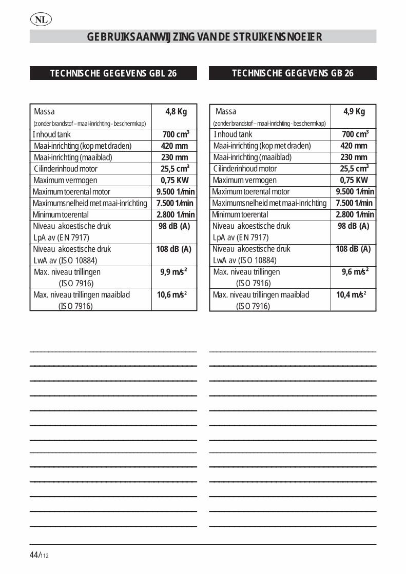
44/112
GEBRUIKSAANWIJZING VAN DE STRUIKENSNOEIER
NL
TECHNISCHE GEGEVENS GBL 26
Massa 4,8 Kg (zonder brandstof – maai-inrichting - beschermkap)
I nhoud tank 700 cm³ Maai-inrichting (kop met draden) 420 mm Maai-inrichting (maaiblad) 230 mm Cilinderinhoud motor 25,5 cm³ Maximum vermogen 0,75 KW Maximum toerental motor 9.500 1/min Maximumsnelheid met maai-inrichting 7.500 1/min Minimum toerental 2.800 1/min Niveau akoestische druk 98 dB (A) LpA av (EN 7917) Niveau akoestische druk 108 dB (A) LwA av (ISO 10884) Max. niveau trillingen 9,9 m/s² (ISO 7916) Max. niveau trillingen maaiblad 10,6 m/s2
(ISO 7916)
TECHNISCHE GEGEVENS GB 26
Massa 4,9 Kg (zonder brandstof – maai-inrichting - beschermkap)
I nhoud tank 700 cm³ Maai-inrichting (kop met draden) 420 mm Maai-inrichting (maaiblad) 230 mm Cilinderinhoud motor 25,5 cm³ Maximum vermogen 0,75 KW Maximum toerental motor 9.500 1/min Maximumsnelheid met maai-inrichting 7.500 1/min Minimum toerental 2.800 1/min Niveau akoestische druk 98 dB (A) LpA av (EN 7917) Niveau akoestische druk 108 dB (A) LwA av (ISO 10884) Max. niveau trillingen 9,6 m/s² (ISO 7916) Max. niveau trillingen maaiblad 10,4 m/s2
(ISO 7916)
__________________________________________________________________________________________________________________________________________________________________________________________________________________________________________________________________________________________________________________________________________________________________________________________________________________________________________________________________________________
__________________________________________________________________________________________________________________________________________________________________________________________________________________________________________________________________________________________________________________________________________________________________________________________________________________________________________________________________________________

45/112
NL
GEBRUIKSAANWIJZING VAN DE STRUIKENSNOEIER
__________________________________________________________________________________________________________________________________________________________________________________________________________________________________________________________________________________________________________________________________________________________________________________________________________________________________________________________________________________
__________________________________________________________________________________________________________________________________________________________________________________________________________________________________________________________________________________________________________________________________________________________________________________________________________________________________________________________________________________
TECHNISCHE GEGEVENS GBL 34
Massa 5,9 Kg (zonder brandstof – maai-inrichting - beschermkap)
I nhoud tank 830 cm³ Maai-inrichting (kop met draden) 420 mm Maai-inrichting (maaiblad) 230 mm Cilinderinhoud motor 33,6 cm³ Maximum vermogen 1 KW Maximum toerental motor 9.500 1/min Maximumsnelheid met maai-inrichting 7.500 1/min Minimum toerental 2.800 1/min Niveau akoestische druk 97 dB (A) LpA av (EN 7917) Niveau akoestische druk 107 dB (A) LwA av (ISO 10884) Max. niveau trillingen 8 m/s² (ISO 7916) Max. niveau trillingen maaiblad 8,9 m/s2
(ISO 7916)
TECHNISCHE GEGEVENS GB 34
Massa 6,0 Kg (zonder brandstof – maai-inrichting - beschermkap)
I nhoud tank 830 cm³ Maai-inrichting (kop met draden) 420 mm Maai-inrichting (maaiblad) 230 mm Cilinderinhoud motor 33,6 cm³ Maximum vermogen 1 KW Maximum toerental motor 9.500 1/min Maximumsnelheid met maai-inrichting 7.500 1/min Minimum toerental 2.800 1/min Niveau akoestische druk 97 dB (A) LpA av (EN 7917) Niveau akoestische druk 107 dB (A) LwA av (ISO 10884) Max. niveau trillingen 5,6 m/s² (ISO 7916) Max. niveau trillingen maaiblad 6,2 m/s2
(ISO 7916)
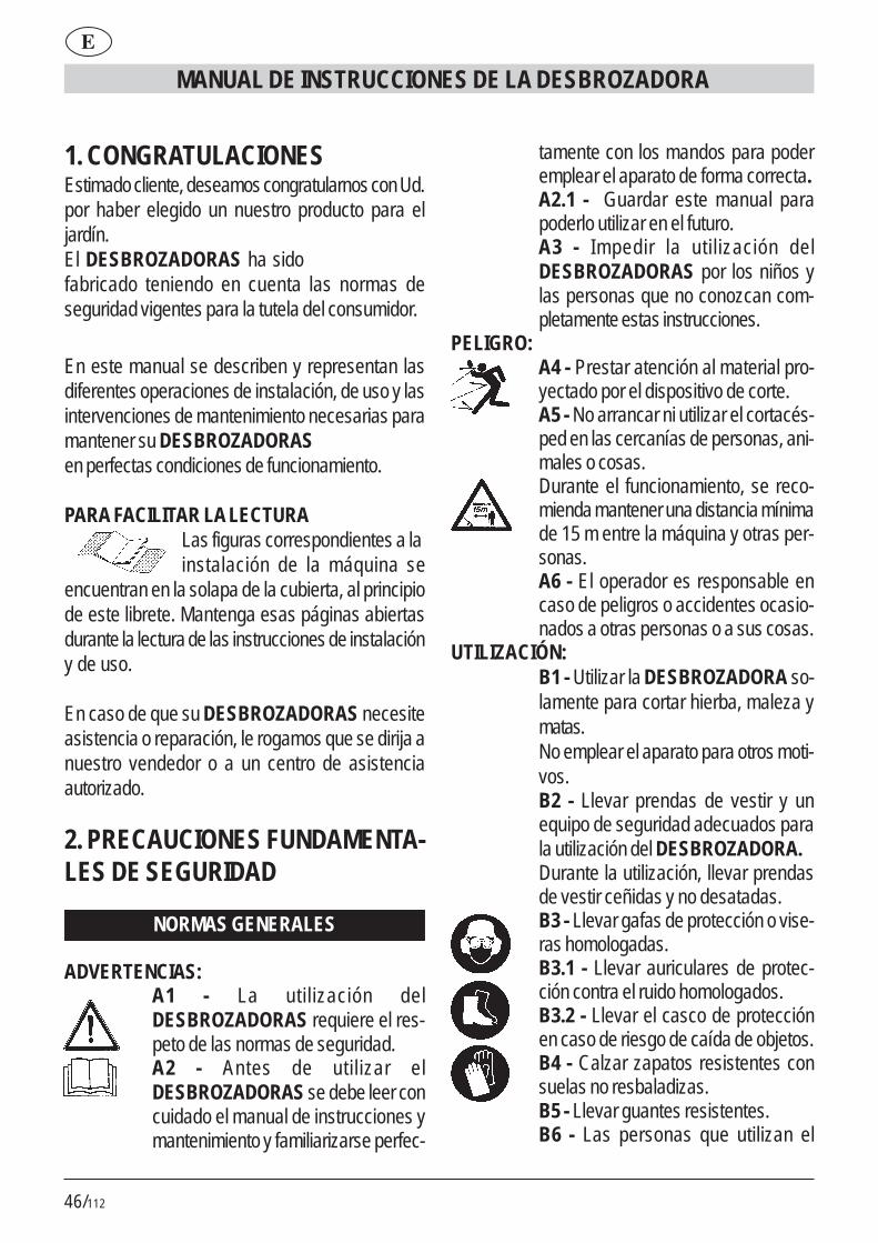
46/112
MANUAL DE INSTRUCCIONES DE LA DESBROZADORA
E
1. CONGRATULACIONESEstimado cliente, deseamos congratularnos con Ud.por haber elegido un nuestro producto para eljardín.El DESBROZADORAS ha sidofabricado teniendo en cuenta las normas deseguridad vigentes para la tutela del consumidor.
En este manual se describen y representan lasdiferentes operaciones de instalación, de uso y lasintervenciones de mantenimiento necesarias paramantener su DESBROZADORAS en perfectas condiciones de funcionamiento.
PARA FACILITAR LA LECTURALas figuras correspondientes a lainstalación de la máquina se
encuentran en la solapa de la cubierta, al principiode este librete. Mantenga esas páginas abiertasdurante la lectura de las instrucciones de instalacióny de uso.
En caso de que su DESBROZADORAS necesiteasistencia o reparación, le rogamos que se dirija anuestro vendedor o a un centro de asistenciaautorizado.
2. PRECAUCIONES FUNDAMENTA-LES DE SEGURIDAD
NORMAS GENERALES
ADVERTENCIAS:A1 - La utilización delDESBROZADORAS requiere el res-peto de las normas de seguridad.A2 - Antes de utilizar elDESBROZADORAS se debe leer concuidado el manual de instrucciones ymantenimiento y familiarizarse perfec-
tamente con los mandos para poderemplear el aparato de forma correcta.A2.1 - Guardar este manual parapoderlo utilizar en el futuro.A3 - Impedir la utilización delDESBROZADORAS por los niños ylas personas que no conozcan com-pletamente estas instrucciones.
PELIGRO:A4 - Prestar atención al material pro-yectado por el dispositivo de corte.A5 - No arrancar ni utilizar el cortacés-ped en las cercanías de personas, ani-males o cosas.Durante el funcionamiento, se reco-mienda mantener una distancia mínimade 15 m entre la máquina y otras per-sonas.A6 - El operador es responsable encaso de peligros o accidentes ocasio-nados a otras personas o a sus cosas.
UTILIZACIÓN:B1 - Utilizar la DESBROZADORA so-lamente para cortar hierba, maleza ymatas.No emplear el aparato para otros moti-vos.B2 - Llevar prendas de vestir y unequipo de seguridad adecuados parala utilización del DESBROZADORA.Durante la utilización, llevar prendasde vestir ceñidas y no desatadas.B3 - Llevar gafas de protección o vise-ras homologadas.B3.1 - Llevar auriculares de protec-ción contra el ruido homologados.B3.2 - Llevar el casco de protecciónen caso de riesgo de caída de objetos.B4 - Calzar zapatos resistentes consuelas no resbaladizas.B5 - Llevar guantes resistentes.B6 - Las personas que utilizan el

47/112
E
MANUAL DE INSTRUCCIONES DE LA DESBROZADORA
DESBROZADORA deben estar enbuena forma. NO UTILIZAR elDESBROZADORA en condiciones decansancio, de malestar o bajo los efec-tos del alcohol y de otras drogas.B7 - ¡ATENCIÓN! Los gases de esca-pe son venenosos y asfixiantes. Por lotanto, de inhalarlos pueden ser inclusomortales. No dejar funcionar el motoren un lugar cerrado o con una ventila-ción insuficiente.B8 - La utilización del aparato por lar-go tiempo puede causar problemas decirculación sanguínea a las manos (en-fermedad de los dedos blancos) impu-tables a las vibraciones.Factores que influyen en la apariciónde estos problemas pueden ser:- Predisposición personal del opera-dor a una escasa irrigación sanguíneade las manos.- Utilización del aparato a bajas tempe-raturas (por lo tanto, se aconsejanguantes calientes).- Largos tiempos de utilización sin inte-rrupciones (se aconseja una utilizacióna intervalos).- En caso de aparición de formicacióny entorpecimiento, se recomienda diri-girse a un médico.B8.1 - Aguantar el aparato siempre conambas manos.Tomar una posición estable y segurasobre las piernas.B8.2 - El DESBROZADORA está di-señado para ser utilizado en el ladoderecho del operador (véase fig.37-38).Tener la empuñadura trasera (conmandos) con la mano derecha y laempuñadura delantera con la manoizquierda.
B9 - ¡ATENCIÓN! La gasolina y susvapores son extremadamente inflama-bles.PELIGRO DE QUEMADURAS E IN-CENDIO.B9.1 - Parar el motor antes de repos-tar combustible.B9.2 - No fumar durante el repostajede combustible.B9.3 - Secar el combustible que sehaya derramado. Arrancar el motorlejos del lugar de repostaje.B9.4 - Asegurarse de que el tapón deldepósito esté enroscado perfectamente.Prestar atención a eventuales pérdi-das.B10 - Junto con el aparato, se suminis-tra una PROTECCIÓN DEL DISPO-SITIVO DE CORTE (Fig.1 piezas 21)que se debe instalar antes de la utiliza-ción (véase instrucciones de instala-ción).No arrancar ni utilizar el aparato si noestá dotado de la protección.B10.1 - ¡PELIGRO! Heridas causa-das por el contacto con el dispositivode corte; proyección de material haciael operador.No modificar la protección.Sustituir la protección, si está dañada,solamente con un repuesto original.B10.2 - ¡PELIGRO! No instalar alam-bre metálico en la cabeza de corte.B10.3 - El BLOQUEO DEL MANDODEL ACELERADOR (véase fig.1 pie-za 16): impide el accionamiento acci-dental de la palanca del acelerador.B10.4 - INTERRUPTOR (ON/OFF)de parada del motor (fig.1 pieza 14).¡PELIGRO! Atención, el dispositivo decorte sigue girando durante cierto tiem-po, incluso después del accionamiento

48/112
del interruptor en posición «OFF». Te-ner con fuerza las dos empuñadurashasta la parada total. Véase capítuloPUESTA EN MARCHA Y PARADA.B10.5 ¡PELIGRO! No instalar ho-jas de sierra.B10.6 ¡PELIGRO! No instalar ho-jas formadas por varias piezas,sino solamente hojas monolíticas.B10.7 ¡PELIGRO! No instalar ho-jas de diámetro superior a 230 mm.
3. DESCRIPCIONES DE LAS PIEZASDE LA MÁQUINA
DESCRIPCIÓN Fig.11) Asa del cable de puesta en marcha2) Arrancador3) Palanca del aire4) Capuchón de la bujía5) Tapón depósito combustible6) Silenciador7) Empuñadura izquierda (manillar)8) Motor de explosión9) Depósito combustible10) Empuñadura derecha con mandos (ma-
nillar)11) Empuñadura con mandos trasera12) Punto de unión para correa13) Empuñadura delantera14) Dispositivo de parada del motor ON/OFF15) Bloqueo medio acelerador16) Bloqueo del mando del acelerador17) Palanca del acelerador18) Tubo de transmisión (varilla)19) Hoja20) Protección dispositivo de corte (para hoja)21) Protección dispositivo de corte (para ca-
beza de hilos)22) Dispositivo de corte (cabeza de hilos)
MANUAL DE INSTRUCCIONES DE LA DESBROZADORA
E
23) Embrague de correa24) Barrera
4. INSTALACIÓNEMPUÑADURA DELANTERA PARA MODELOGBL 26/341) Situar la empuñadura (pieza 1) y la barrera (pie-za 2) del modo indicado en la fig.2.2) Bloquear con los n.°4 tornillos, arandelas ytuercas (fig.3)La barrera tiene la función de asegurar unadistancia de seguridad entre el operador y eldispositivo de corte.
MANILLAR CON EMPUÑADURA PARA MODE-LO GB 26/341) La DESBROZADORA se embala con el manillarplegado (fig.4).2) Aflojar el pomo (fig.5) y girar el manillar en senti-do transversal.3) Bloquear el manillar apretando hasta el fondo elpomo (fig.6).El manillar se puede plegar para facilitar el trans-porte o la colocación en caso de inactividad, o sepuede regular para obtener una posición de traba-jo más cómoda.
Las DESBROZADORAS GB 26/34 y GBL 26/34 se pueden utilizar:A. Para desbrozar, instalando la hoja y la protec-ción de la hoja (fig.1 piezas 19-20).B. Para el corte de hierba, instalando la cabeza dehilos y el prolongador (fig.1 piezas 21-22), que seenrosca en la protección misma.
¡ATENCIÓN! Las condiciones de seguridad previstas por las normas vi-
gentes se obtienen solamente instalando lasprotecciones del modo arriba descrito.
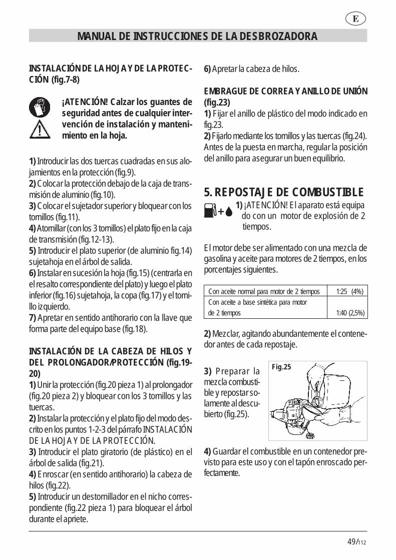
49/112
E
MANUAL DE INSTRUCCIONES DE LA DESBROZADORA
INSTALACIÓN DE LA HOJA Y DE LA PROTEC-CIÓN (fig.7-8)
¡ATENCIÓN! Calzar los guantes deseguridad antes de cualquier inter-vención de instalación y manteni-miento en la hoja.
1) Introducir las dos tuercas cuadradas en sus alo-jamientos en la protección (fig.9).2) Colocar la protección debajo de la caja de trans-misión de aluminio (fig.10).3) Colocar el sujetador superior y bloquear con lostornillos (fig.11).4) Atornillar (con los 3 tornillos) el plato fijo en la cajade transmisión (fig.12-13).5) Introducir el plato superior (de aluminio fig.14)sujetahoja en el árbol de salida.6) Instalar en sucesión la hoja (fig.15) (centrarla enel resalto correspondiente del plato) y luego el platoinferior (fig.16) sujetahoja, la copa (fig.17) y el torni-llo izquierdo.7) Apretar en sentido antihorario con la llave queforma parte del equipo base (fig.18).
INSTALACIÓN DE LA CABEZA DE HILOS YDEL PROLONGADOR/PROTECCIÓN (fig.19-20)1) Unir la protección (fig.20 pieza 1) al prolongador(fig.20 pieza 2) y bloquear con los 3 tornillos y lastuercas.2) Instalar la protección y el plato fijo del modo des-crito en los puntos 1-2-3 del párrafo INSTALACIÓNDE LA HOJA Y DE LA PROTECCIÓN.3) Introducir el plato giratorio (de plástico) en elárbol de salida (fig.21).4) Enroscar (en sentido antihorario) la cabeza dehilos (fig.22).5) Introducir un destornillador en el nicho corres-pondiente (fig.22 pieza 1) para bloquear el árboldurante el apriete.
6) Apretar la cabeza de hilos.
EMBRAGUE DE CORREA Y ANILLO DE UNIÓN(fig.23)1) Fijar el anillo de plástico del modo indicado enfig.23.2) Fijarlo mediante los tornillos y las tuercas (fig.24).Antes de la puesta en marcha, regular la posicióndel anillo para asegurar un buen equilibrio.
5. REPOSTAJE DE COMBUSTIBLE 1) ¡ATENCIÓN! El aparato está equipa do con un motor de explosión de 2 tiempos.
El motor debe ser alimentado con una mezcla degasolina y aceite para motores de 2 tiempos, en losporcentajes siguientes.
Con aceite normal para motor de 2 tiempos 1:25 (4%) Con aceite a base sintética para motor de 2 tiempos 1:40 (2,5%)
2) Mezclar, agitando abundantemente el contene-dor antes de cada repostaje.
3) Preparar lamezcla combusti-ble y repostar so-lamente al descu-bierto (fig.25).
Fig.25
4) Guardar el combustible en un contenedor pre-visto para este uso y con el tapón enroscado per-fectamente.
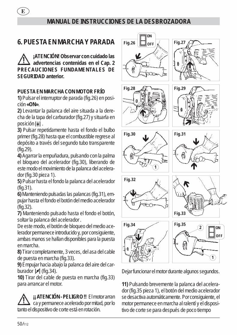
50/112
6. PUESTA EN MARCHA Y PARADA
¡ATENCIÓN! Observar con cuidado lasadvertencias contenidas en el Cap. 2
PRECAUCIONES FUNDAMENTALES DESEGURIDAD anterior.
PUESTA EN MARCHA CON MOTOR FRÍO1) Pulsar el interruptor de parada (fig.26) en posi-ción «ON».2) Levantar la palanca del aire situada a la dere-cha de la tapa del carburador (fig.27) y situarla enposición .3) Pulsar repetidamente hasta el fondo el bulboprimer (fig.28) hasta que el combustible regrese aldepósito a través del segundo tubo transparente(fig.29).4) Agarrar la empuñadura, pulsando con la palmael bloqueo del acelerador (fig.30), liberando deeste modo el movimiento de la palanca del acelera-dor (fig.30 pieza 1).5) Pulsar hasta el fondo la palanca del acelerador(fig.31).6) Manteniendo pulsadas las palancas (fig.31), em-pujar hasta el fondo el botón del medio acelerador(fig.32).7) Manteniendo pulsado hasta el fondo el botón,soltar la palanca del acelerador .De este modo, el botón de bloqueo del medio ace-lerador permanece introducido y, por consiguiente,ambas manos se hallan disponibles para la puestaen marcha.8) Tirar completamente, 3 veces, del asa del cablede puesta en marcha (fig.33).9) Empujar hacia abajo la palanca del aire del car-burador (fig.34).10) Tirar del cable de puesta en marcha (fig.33)para arrancar el motor.
¡¡ ATENCIÓN - PELIGRO !! El motor arranca y permanece acelerado por mitad, por lo
tanto el dispositivo de corte está en rotación.
MANUAL DE INSTRUCCIONES DE LA DESBROZADORA
E
Fig.27
Fig.28 Fig.29
Fig.30 Fig.31
Fig.32
Fig.33
Fig.34 Fig.35
�
�
�
�
�
�
� �
�
1
2
1
Fig.26
�
ON
OFF
ON
OFF
Dejar funcionar el motor durante algunos segundos.
11) Pulsando brevemente la palanca del acelera-dor (fig.35 pieza 1), el botón del medio aceleradorse desactiva automáticamente. Por consiguiente, elmotor permanece en marcha al ralentí y el disposi-tivo de corte se para después de poco tiempo

51/112
E
MANUAL DE INSTRUCCIONES DE LA DESBROZADORA
PARADA MOTOR
1) Para parar el motor, situar el interruptor (fig.35pieza 2) en posición «OFF».
¡ATENCIÓN! el dispositivo de corte siguegirando durante cierto tiempo, incluso des-
pués del accionamiento del interruptor en posición«OFF». Tener con fuerza las dos empuñadurashasta la parada total.
PUESTA EN MARCHA CON MOTOR CALIENTEActuar al igual que para el motor frío, pero con lapalanca del aire bajada (véase fig.34).
7. UTILIZACIÓNCÓMO UTILIZAR EL CORTACÉSPED1) Enganchar el embrague de correa (fig.36 pieza1) al anillo (fig.36 pieza 2).2) Mantener el aparato en el lado derecho, segúnse indica en fig.37-38.
AJUSTE DE LA LONGITUD DEL HILO DE COR-TELa cabeza de hilos que forma parte del equipobase es del tipo con regulación manual.Antes de que el hilo de corte se haya desgastadohasta la mitad de su longitud, restablecer la longitudtirando del carrete y luego girándolo (fig.39).En caso de que la cantidad de hilo extraído seaexcesiva, la longitud se regula automáticamente porla especial hoja durante la rotación.
CORTE DE HIERBAManteniendo la cabeza de corte paralela al terre-no, avanzar oscilando a la derecha e izquierda(fig.40). Mantener el motor a su régimen máximopara efectuar el corte neto.
CORTE ALREDEDOR DE OBSTÁCULOS, PLAN-TAS Y CERCASRozar el obstáculo con la extremidad del hilo (fig.40).La inclinación de la cabeza (fig.41) puede mejorarla eficacia del corte. No chocar la cabeza de cortecontra los obstáculos para evitar roturas netas delos hilos.En caso de rotura de los hilos, actuar al igual quepara la sustitución.
8. SUSTITUCIÓN DEL HILOPara enrollar un hilo nuevo en el carrete original:A) Utilizar hilo de 2 mm de diámetro, de plástico,específico para cortacéspedes de hilo.
¡ATENCIÓN PELIGRO! NO UTILIZARNUNCA HILO METÁLICO. REALIZAR
LA OPERACIÓN CON EL MOTOR PARADO
B) DESMONTAJE DE LA BOBINA1) Desenroscar en sentido horario la tuerca demariposa (fig.42).2) Extraer el carrete (fig.43-44-45).3) Limpiar con cuidado el interior del cuerpo (fig.46).
C) ENROLLAMIENTO DEL HILO1) Preparar dos tramos de hilo no superiores a 6 m.2) Introducir la extremidad de los dos hilos en los 2agujeros correspondientes (fig.47).3) Enrollar los dos tramos de hilo acoplados en elcarrete, siguiendo el sentido de la flecha impresasobre el carrete mismo (fig.48).4) Para facilitar la introducción del carrete en elcuerpo, fijar las dos extremidades del hilo en lasdos ranuras correspondientes (fig.49).
D) INSTALACIÓN DEL CARRETE1) Introducir las dos extremidades a través de losguiahilos (fig.50).2) Introducir el carrete y tirar con fuerza de las dosextremidades del hilo para extraerlas de las ranu-ras (fig.51).

52/112
3) Volver a instalar el muelle (fig.52) y enroscar latuerca de mariposa en sentido antihorario (fig.53).
9. MANTENIMIENTOBUJÍAPor lo menos una vez al año o en caso de dificultadde arranque, comprobar el estado de la bujía deencendido. Antes de efectuar esta operación, es-perar a que el motor se enfríe.1) Extraer el capuchón y desenroscar la bujía conla llave que forma parte del equipo base (fig.54).En caso de incrustaciones excesivas y de un des-gaste considerable de los electrodos, sustituir labujía con otra de tipo equivalente (fig.55-56).Un exceso de incrustaciones puede depender de:# Porcentaje excesivo de aceite en el combustibley/o calidad inadecuada del aceite.# Filtro de aire parcialmente atascado.2) Enroscar la bujía manualmente hasta el tope dela rosca, para evitar dañar su alojamiento. Utilizarla llave correspondiente sólo para el apriete (fig.54).
FILTRO DE AIRELimpiar periódicamente el filtro de aire; con frecuen-cia, si se opera en áreas polvorientos.1) Destornillar el tornillo de mariposa de la tapa(fig.57).2) Lavar con agua y detergente neutro.3) Dejar secar el filtro antes de volver a instalarlo(fig.58).Sustituir el filtro, si está dañado, para evitarperjudicar la duración del motor.
FILTRO PESCANTE DEL COMBUSTIBLESustituir una vez al año el filtro, extrayéndolo conun gancho a través del orificio de llenado del depó-sito.
REDECILLA PARACHISPAS DEL SILENCIA-DOR# En el agujero de escape del gas está introducidoun anillo con redecilla (parte más saliente).
# A causa de los depósitos, la redecilla tiende aatascarse, reduciendo las prestaciones del motorde forma considerable.# Extraer el anillo con redecilla por medio de unapinza de puntas (fig.59).
RALENTÍ DEL MOTOR# Antes de cada utilización, comprobar queal ralentí el dispositivo de corte no esté enrotación.
# Si tiende a girar, dirigirse a un centro de asistenciapara la intervención de regulación.
COMPROBACIÓN DE TORNILLOS Y PIEZASGIRATORIAS# Antes de cada utilización, controlar que no hayatornillos o piezas aflojadas, ni grietas o señales sen-sibles de desgaste en el dispositivo de corte.# Sustituir las piezas dañadas antes de la utilización.
LIMPIEZA Y COLOCACIÓN EN CASO DE IN-ACTIVIDAD# En caso de interrupción de la utilización superiora 2 meses, vaciar el depósito del combustible.# No limpiar con líquidos agresivos.# Guardar el aparato en un lugar seco y seguro,inaccesible a los niños.# Antes de efectuar el transporte, vaciar el depósitode combustible y proteger la hoja (si está instalada)con una protección específica.
MANUAL DE INSTRUCCIONES DE LA DESBROZADORA
E
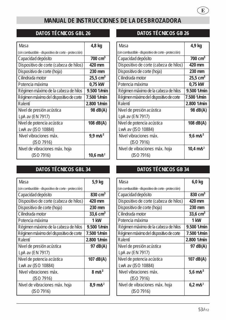
53/112
E
MANUAL DE INSTRUCCIONES DE LA DESBROZADORA
DATOS TÉCNICOS GBL 26
Masa 4,8 kg (sin combustible - dispositivo de corte - protección)
Capacidad depósito 700 cm³ Dispositivo de corte (cabeza de hilos) 420 mm Dispositivo de corte (hoja) 230 mm Cilindrada motor 25,5 cm³ Potencia máxima 0,75 kW Régimen máximo de la cabeza de hilos 9.500 1/min Régimen máximo del dispositivo de corte 7.500 1/min Ralentí 2.800 1/min Nivel de presión acústica 98 dB(A) LpA av (EN 7917) Nivel de potencia acústica 108 dB(A) LwA av (ISO 10884) Nivel vibraciones máx. 9,9 m/s² (ISO 7916) Nivel de vibraciones máx. hoja
(ISO 7916) 10,6 m/s2
DATOS TÉCNICOS GB 26
Masa 4,9 kg (sin combustible - dispositivo de corte - protección)
Capacidad depósito 700 cm³ Dispositivo de corte (cabeza de hilos) 420 mm Dispositivo de corte (hoja) 230 mm Cilindrada motor 25,5 cm³ Potencia máxima 0,75 kW Régimen máximo de la cabeza de hilos 9.500 1/min Régimen máximo del dispositivo de corte 7.500 1/min Ralentí 2.800 1/min Nivel de presión acústica 98 dB(A) LpA av (EN 7917) Nivel de potencia acústica 108 dB(A) LwA av (ISO 10884) Nivel vibraciones máx. 9,6 m/s² (ISO 7916) Nivel de vibraciones máx. hoja 10,4 m/s2
(ISO 7916)
DATOS TÉCNICOS GBL 34
Masa 5,9 kg (sin combustible - dispositivo de corte - protección)
Capacidad depósito 830 cm³ Dispositivo de corte (cabeza de hilos) 420 mm Dispositivo de corte (hoja) 230 mm Cilindrada motor 33,6 cm³ Potencia máxima 1 kW Régimen máximo de la cabeza de hilos 9.500 1/min Régimen máximo del dispositivo de corte 7.500 1/min Ralentí 2.800 1/min Nivel de presión acústica 97 dB(A) LpA av (EN 7917) Nivel de potencia acústica 107 dB(A) LwA av (ISO 10884) Nivel vibraciones máx. 8 m/s² (ISO 7916) Nivel de vibraciones máx. hoja 8,9 m/s2
(ISO 7916)
DATOS TÉCNICOS GB 34
Masa 6,0 kg (sin combustible - dispositivo de corte - protección)
Capacidad depósito 830 cm³ Dispositivo de corte (cabeza de hilos) 420 mm Dispositivo de corte (hoja) 230 mm Cilindrada motor 33,6 cm³ Potencia máxima 1 kW Régimen máximo de la cabeza de hilos 9.500 1/min Régimen máximo del dispositivo de corte 7.500 1/min Ralentí 2.800 1/min Nivel de presión acústica 97 dB(A) LpA av (EN 7917) Nivel de potencia acústica 107 dB(A) LwA av (ISO 10884) Nivel vibraciones máx. 5,6 m/s² (ISO 7916) Nivel de vibraciones máx. hoja 6,2 m/s2
(ISO 7916)

54/112
MANUAL DE INSTRUÇÕES DA ROÇADORAP
A2.1 - Conserve este manual paraconsultas futuras.A3 – Não permita o uso doROÇADORAS às crianças e a pesso-as que não conheçam completamenteestas instruções.
PERIGO:A4 – Tenha cuidado com o materialarremessado pelo dispositivo de corte.A5 – Não ponha em funcionamento nemutilize o aparador de relva nas proxi-midades de pessoas, animais ou coi-sas.Durante o funcionamento recomenda-se uma distância mínima de 15 m entrea máquina e outras pessoas.A6 – O operador é responsável emcaso de acidentes ou perigos causa-dos a outras pessoas ou às coisas de-las.
EMPREGO:B1 – Utilize a ROÇADORA somentepara cortar relva, ervas ruins e moitas.Não empregue o aparelho para finali-dades diferentes.Não utilize o aparelho para finalidadesdiferentes.B2 – Vista roupa e equipamento desegurança adequado para o empregodo ROÇADORA.Durante o emprego vista roupa justaao corpo e não solta.B3 – Utilize óculos de protecção ou vi-seira homologados.B3.1 – Utilize protectores auriculareshomologados contra o ruído.B3.2 – Utilize o capacete de protecçãoem caso de risco de queda de objec-tos.B4 – Calce sapatos robustos com so-las anti-derrapantes.B5 – Utilize luvas grossas.
1. PARABÉNSPrezado Cliente, parabéns por ter escolhido umnosso produto para o jardim.
O Seu ROÇADORAS foi construído norespeito das normas de segurança em vigor emdefesa do consumidor.
Neste manual são descritas e ilustradas as váriasoperações de montagem, de uso e as operaçõesde manutenção necessárias para manter em perfeitaeficiência o Seu ROÇADORAS.
PARA FACILITAR A LEITURAAs ilustrações correspondentes àmontagem da máquina encontram-
se na orelha da capa, no início deste manual.Mantenha abertas estas páginas durante a leituradas instruções de montagem e de utilização.
Caso o Seu ROÇADORAS necessite de assistência ou reparação, rogamosque se dirija ao nosso revendedor, ou a um centrode assistência autorizado.
2. PRECAUÇÕES FUNDAMENTAISDE SEGURANÇA
NORMAS GERAIS
ADVERTÊNCIASA1 – O emprego do ROÇADORASexige o respeito das normas de segu-rança.A2 – Quem quer utilize o ROÇADORASdeve primeiro ler com atenção o ma-nual de instruções e manutenção e fa-miliarizar-se completamente com os co-mandos para um uso correcto do apa-relho.
55/112
MANUAL DE INSTRUÇÕES DA ROÇADORA
P
B6 – Quem utilizar o ROÇADORA deveestar em boas condições. NÃO UTILI-ZE O ROÇADORA em condições decansaço, de mal estar ou sob o efeitodo álcool e de outras drogas.B7 - ATENÇÃO! Os gases de descar-ga são venenosos e asfixiantes. Se ins-pirados, portanto, até podem ser mor-tais. Não ponha em funcionamento omotor num local fechado ou com venti-lação escassa.B8 – O emprego prolongado do apa-relho pode causar problemas de cir-culação sanguínea nas mãos (doença“dos dedos brancos”) atribuível às vi-brações.Factores que influem na manifestaçãodos distúrbios podem ser:- Predisposição pessoal do operadora uma escassa irroração sanguíneadas mãos.- Utilização do aparelho a baixas tem-peraturas (aconselham-se portanto lu-vas quentes).- Longos tempos de uso sem interrup-ção (aconselha-se uma utilização comintervalos).- Ao se manifestarem formigueiro e en-torpecimento, recomenda-se a consul-tar um médico.B8.1 – Sustentar o aparelho semprecom ambas as mãos.Assumir uma posição estável e seguranas pernas.B8.2 - O ROÇADORA é projectadopara ser utilizado no lado direito do ope-rador (veja a fig.37-38).Segure a pega posterior (com coman-dos) com a mão direita e a pega ante-rior com a mão esquerda.B9 - ATENÇÃO! a gasolina e os seusvapores são extremamente inflamáveis.
PERIGO DE QUEIMADURAS E IN-CÊNDIOB9.1 – Pare o motor antes do abaste-cimento.B9.2 – Não fume enquanto estiver aabastecer de carburante.B9.3 – Seque o carburante eventual-mente derramado. Ponha em funcio-namento o motor longe do lugar deabastecimento.B9.4 – Assegure-se de que o bujão doreservatório está bem apertado.Preste atenção com eventuais perdas.B10 – Com o aparelho é fornecida umaPROTECÇÃO DO DISPOSITIVO DECORTE (Fig.1 det.21) que deve sermontada antes do emprego (veja asinstruções de montagem).Não ponha em funcionamento nem uti-lize o aparelho se este estiver despro-vido da protecção.B10.1 - PERIGO! Feridas devidas aocontacto com o dispositivo de corte;arremesso de material contra o opera-dor.Não modifique a protecção.Substitua a protecção se danificada,apenas com peças de origem.B10.2 - PERIGO! Não monte fiometálico na cabeça de corte.B10.3 - O BLOQUEIO DO COMAN-DO DO ACELERADOR (veja fig.1det.16): impede o accionamento aci-dental da alavanca do acelerador.B10.4 - INTERRUPTOR (ON/OFF)de paragem do motor (fig.1 det.14).PERIGO! Atenção, o dispositivo decorte continua a girar por um certo tem-po também depois de colocado o inter-ruptor na posição “OFF”. Segure fir-memente as duas pegas até à para-gem completa. Veja o capítulo ARRAN-QUE E PARAGEM.

56/112
B10.5 PERIGO! Não montar lâmi-nas em serra.B10.6 PERIGO! Não montar lâmi-nas constituídas por mais peçasmas apenas lâminas monolíticas.B10.7 PERIGO! Não montar lâmi-nas com diâmetro superior a 230mm.
3. DESCRIÇÕES DAS PARTES DAMÁQUINA
DESCRIÇÃO Fig.11) Pega da corda de arranque2) Arrancador3) Alavanca do ar4) Cachimbo da vela5) Bujão do reservatório do carburante6) Silenciador7) Pega esquerda (guiador)8) Motor de explosão9) Reservatório do carburante10) Pega direita com comandos (guiador)11) Pega comandos posterior12) Ponto de junção para correia13) Pega anterior14) Dispositivo de paragem do motor ON/OFF.15) Bloqueio do meio acelerador16) Bloqueio do comando do acelerador17) Alavanca do acelerador18) Tubo de transmissão (haste)19) Lâmina20) Protecção do dispositivo de corte (para
lâmina)21) Protecção do dispositivo de corte (para
cabeça de fios)22) Dispositivo de corte (cabeça de fios)23) Correia em tiracolo24) Barreira
4. MONTAGEMPEGA ANTERIOR PARA MODELO GBL 26/341) Posicione como ilustrado na fig.2 a pega (det.1)e a barreira (det.2).2) Bloqueie com os 4 parafusos, anilhas e porcas(fig.3)A barreira tem a função de assegurar uma dis-tância de segurança entre o operador e o dis-positivo de corte.
GUIADOR COM PEGA PARA MODELO GB26/341) A ROÇADORA é embalada como o guiador do-brado (fig.4).2) Desaperte a maçaneta (fig.5) e rode o guiadortransversalmente.3) Bloqueie o guiador apertando a fundo a maça-neta (fig.6).O guiador pode ser dobrado por comodidade detransporte ou armazenagem, como também podeser regulado para uma posição de trabalho maiscómoda.
As ROÇADORAS GB26/34 e GBL 26/34 podem ser utilizadas:A. Para roçar, montando a lâmina e a protecção dalâmina (fig.1 det.19-20).B. Para cortar a relva, montando a cabeça de fios ea extensão (fig.1 det.21-22), que é atarraxada namesma protecção.
ATENÇÃO! As condições de seguran-ça previstas pelas normas em vigor-
só se realizam montando as protecções damaneira descrita acima.
MONTAGEM DE LÂMINA E PROTECÇÃO (fig.7-8)
ATENÇÃO! Utilizar as luvas de segu-rança para todas as operações demontagem e manutenção da lâmina.
MANUAL DE INSTRUÇÕES DA ROÇADORAP
57/112
1) Introduza as duas porcas quadradas nas pró-prias sedes na protecção (fig.9).2) Posicione a protecção por baixo da caixa detransmissão em alumínio (fig.10).3) Posicione o grampo superior e bloqueie com osparafusos (fig.11).4) Aparafuse (com os 3 parafusos) o disco fixo nacaixa de transmissão (fig.12-13).5) Insira o disco superior (em alumínio fig.14) debloqueio da lâmina no veio de saída.6) Monte em sequência a lâmina (fig.15) (centre-ana saliência especial no disco) e a seguir o discoinferior (fig.16) de bloqueio da lâmina, a peça emforma de taça (fig. 17) e o parafuso esquerdo.7) Aperte para a esquerda com a chave anexa(fig.18).
MONTAGEM DA CABEÇA DE FIOS E DA EX-TENSÃO/PROTECÇÃO (fig.19-20)1) Junte a protecção (fig.20 det.1) com a extensão(fig.20 det.2) e bloqueie com os 3 parafusos e asporcas.2) Monte a protecção e o disco fixo como descritonos pontos 1-2-3 do parágrafo MONTAGEM DELÂMINA E PROTECÇÃO.3) Insira o disco rotativo (em plástico) no veio desaída (fig.21).4) Atarraxe (em sentido anti-horário) a cabeça defios (fig. 22).5) Introduza uma chave de fendas na cavidadeespecial (fig. 22 det. 1) para bloquear o veio du-rante o aperto.6) Aperte a cabeça de fios.
CORREIA EM TIRACOLO E ANEL DE JUNÇÃO(fig.23)1) Fixe o anel em plástico como ilustrado na fig.23.2) Fixe-o por meio dos parafusos e das porcas (fig.24). Antes do arranque, regule a posição do anelpara um bom equilíbrio.
MANUAL DE INSTRUÇÕES DA ROÇADORA
P
Fig.25
5. ABASTECIMENTO DE CARBU-RANTE
1) ATENÇÃO! O aparelho está equi pado com um motor de explosão a 2
tempos.
O motor deve ser alimentado com uma mistura degasolina e óleo para motores a 2 tempos, nas per-centagens que seguem:
Com óleo normal para motor a 2 tempos 1:25 (4%) Com óleo à base sintética para motor a 2 tempos 1:40 (2,5%)
2) Misture, agitando abundantemente o recipiente,antes de cada abastecimento.
3) Prepare a mis-tura de carburan-te e abasteça amáquina somenteao ar livre (fig.25).
4) Conserve o carburante num recipiente própriopara esse fim e com tampão bem apertado.
6. ARRANQUE E PARAGEM
ATENÇÃO! Cumprir com atenção osavisos contidos no precedente Cap. 2
PRECAUÇÕES FUNDAMENTAIS DE SEGU-RANÇA.
ARRANQUE COM MOTOR FRIO1) Pressione o interruptor de paragem (fig.26) naposição “ON”.2) Levante a pequena alavanca do ar posta à di-reita da tampa do carburador (fig.27) e coloque-ana posição .
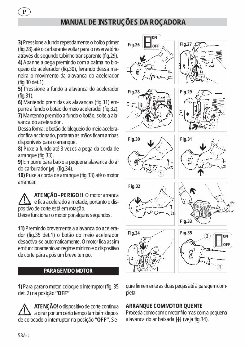
58/112
MANUAL DE INSTRUÇÕES DA ROÇADORAP
3) Pressione a fundo repetidamente o bolbo primer(fig.28) até o carburante voltar para o reservatórioatravés do segundo tubinho transparente (fig.29).4) Apanhe a pega premindo com a palma no blo-queio do acelerador (fig.30), livrando dessa ma-neira o movimento da alavanca do acelerador(fig.30 det.1).5) Pressione a fundo a alavanca do acelerador(fig.31).6) Mantendo premidas as alavancas (fig.31) em-purre a fundo o botão do meio acelerador (fig.32).7) Mantendo premido a fundo o botão, solte a ala-vanca do acelerador .Dessa forma, o botão de bloqueio do meio acelera-dor fica accionado, portanto as mãos ficam ambasdisponíveis para o arranque.8) Puxe a fundo até 3 vezes a pega da corda dearranque (fig.33).9) Empurre para baixo a pequena alavanca do ardo carburador (fig.34).10) Puxe a corda de arranque (fig.33) até o motorarrancar.
ATENÇÃO - PERIGO !! O motor arrancae fica acelerado a metade, portanto o dis-
positivo de corte está em rotação.Deixe funcionar o motor por alguns segundos.
11) Premindo brevemente a alavanca do acelera-dor (fig.35 det.1) o botão do meio aceleradordesactiva-se automaticamente. O motor fica assimem funcionamento ao regime mínimo e o dispositivode corte pára após um breve tempo.
PARAGEM DO MOTOR
1) Para parar o motor, coloque o interruptor (fig. 35det. 2) na posição “OFF”.
ATENÇÃO! o dispositivo de corte continuaa girar por um certo tempo também depois
de colocado o interruptor na posição “OFF”. Se-
Fig.27
Fig.28 Fig.29
Fig.30 Fig.31
Fig.32
Fig.33
Fig.34 Fig.35
�
�
�
�
�
�
� �
�
1
2
1
Fig.26
�
ON
OFF
ON
OFF
gure firmemente as duas pegas até à paragem com-pleta.
ARRANQUE COM MOTOR QUENTEProceda como com o motor frio mas com a pequenaalavanca do ar baixada (veja fig.34).
59/112
MANUAL DE INSTRUÇÕES DA ROÇADORA
P
7. UTILIZAÇÃOCOMO UTILIZAR O APARADOR DE RELVA1) Enganche a correia em tiracolo (fig.36 det.1) noanel (fig.36 det.2).2) Mantenha o aparelho no lado direito como indi-cado na fig.37-38.
AJUSTE DO COMPRIMENTO DO FIO DE COR-TEA cabeça de fios anexa é do tipo de regulaçãomanual.Antes que o fio de corte se gaste até à metade docomprimento, restabeleça o comprimento puxandoe a seguir rodando o carretel (fig.39).Caso a quantidade de fio extraído seja excessiva,o comprimento é regulado automaticamente pelalâmina especial durante a rotação.
CORTE DA RELVAMantendo a cabeça de corte paralela ao terreno,avance oscilando para a direita e para a esquerda(fig. 40). Mantenha o motor a regime elevado paraefectuar um corte preciso.
CORTE EM REDOR DE OBSTÁCULOS, PLAN-TAS, VEDAÇÕESPasse rente ao obstáculo com a extremidade do fio(fig.40). A inclinação da cabeça (fig.41) pode me-lhorar a eficiência do corte. Não bata contra obstá-culos com a cabeça de corte para evitar que os fiosse partam.Em caso de fios partidos, proceda como para asubstituição.
8. SUBSTITUIÇÃO DO FIOPara envolver um fio novo no carretel original:A) Utilize fio de 2 mm de diâmetro em plástico, pró-prio para aparadores de relva a fio.
ATENÇÃO PERIGO! NÃO UTILIZAR-DE NENHUM MODO FIO METÁLICO.
EFECTUAR A OPERAÇÃO COM O MOTOR PA-RADO.
B) DESMONTAGEM DA BOBINA1) Desaperte em sentido horário a porca em bor-boleta (fig.42).2) Extraia o carretel (fig.43-44-45).3) Limpe minuciosamente o interior do corpo (fig.46).
C) ENROLAMENTO DO FIO1) Prepare dois pedaços de fio não superiores a 6 m.2) Introduza a extremidade dos dois fios nos 2 furosespeciais (fig.47).3) Enrole as duas partes de fio emparelhadas nocarretel, seguindo o sentido da seta marcada nopróprio carretel (fig.48).4) Para facilitar a nova inserção do carretel no cor-po, fixe as duas extremidades de fio nas duas fen-das especiais (fig.49).
D) REMONTAGEM DO CARRETEL1) Insira as duas extremidades através do passa-fio (fig.50).2) Insira o carretel e puxe com força as duas extre-midades do fio para que saiam das fendas (fig.51).3) Volte a posicionar a mola (fig.52) e atarraxe aporca em borboleta em sentido anti-horário (fig.53).
9. MANUTENÇÃOVELAPelo menos uma vez por ano ou em caso de dificul-dade de arranque, verifique o estado da vela deignição. Aguarde que o motor arrefeça antes daoperação.1) Extraia o cachimbo e desatarraxe a vela com achave anexa (fig.54).Em caso de incrustações excessivas e notável des-gaste dos eléctrodos, substitua a vela por uma detipo equivalente (fig.55-56).Um excesso de incrustações pode ser devido a:
60/112
# Percentagem excessiva de óleo no carburantee/ou qualidade não adequada do óleo.# Filtro do ar parcialmente entupido.2) Atarraxe a vela à mão até o fundo da rosca paraevitar danos na sua sede. Utilize a chave especialapenas para apertar (fig.54).
FILTRO DO ARLimpe periodicamente o filtro do ar; frequentementese trabalhar em áreas poeirentas.1) Desaperte o parafuso em borboleta da tampa(fig.57).2) Lave com água e detergente neutro.3) Faça secar o filtro antes de voltar a colocá-lo(fig.58).Substitua o filtro se danificado para não com-prometer a duração do motor.
FILTRO DO TUBO DO CARBURANTESubstitua uma vez por ano o filtro extraindo-o comum gancho pela abertura de abastecimento do re-servatório.
REDE PÁRA-FAÍSCAS DO SILENCIADOR# No orifício de descarga do gás está inserido umanel com rede (parte mais saliente).# Devido aos depósitos, a rede tende a entupir-sereduzindo notavelmente os rendimentos do motor.# Extraia o anel com rede por meio de um alicatede pontas longas (fig.59).
REGIME MÍNIMO DO MOTOR# Verifique a cada emprego que ao regimemínimo o dispositivo de corte não esteja em
rotação.# Se tende a rodar, contacte um centro de assistên-cia para a intervenção de regulação.
VERIFICAÇÃO DE PARAFUSOS E PARTESROTATIVAS# Antes de cada emprego controle que não hajaparafusos ou partes desapertadas e que não hajarachas ou fortes desgastes no dispositivo de corte.# Substitua as partes danificadas antes do empre-go.
LIMPEZA E ARMAZENAGEM# Em caso de interrupção de utilização superior a 2meses, esvazie o reservatório do carburante.# Não limpe com líquidos agressivos.# Conserve o aparelho em local seco e seguro,não acessível às crianças.# Em caso de transporte, esvazie o reservatório docarburante e proteja a lâmina (se montada) comuma protecção adequada.
MANUAL DE INSTRUÇÕES DA ROÇADORAP
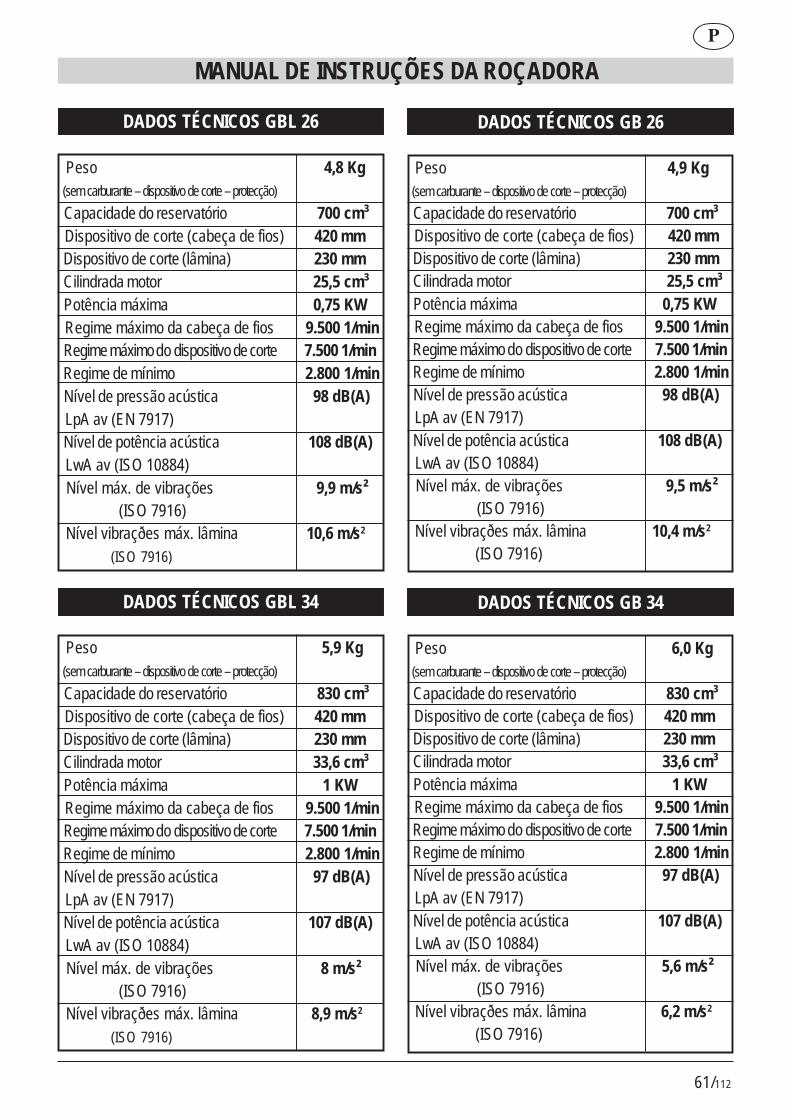
61/112
MANUAL DE INSTRUÇÕES DA ROÇADORA
P
DADOS TÉCNICOS GBL 26
Peso 4,8 Kg (sem carburante – dispositivo de corte – protecção)
Capacidade do reservatório 700 cm³ Dispositivo de corte (cabeça de fios) 420 mm Dispositivo de corte (lâmina) 230 mm Cilindrada motor 25,5 cm³ Potência máxima 0,75 KW Regime máximo da cabeça de fios 9.500 1/min Regime máximo do dispositivo de corte 7.500 1/min Regime de mínimo 2.800 1/min Nível de pressão acústica 98 dB(A) LpA av (EN 7917) Nível de potência acústica 108 dB(A) LwA av (ISO 10884) Nível máx. de vibrações 9,9 m/s² (ISO 7916) Nível vibraçðes máx. lâmina 10,6 m/s2
(ISO 7916)
DADOS TÉCNICOS GB 26
Peso 4,9 Kg (sem carburante – dispositivo de corte – protecção)
Capacidade do reservatório 700 cm³ Dispositivo de corte (cabeça de fios) 420 mm Dispositivo de corte (lâmina) 230 mm Cilindrada motor 25,5 cm³ Potência máxima 0,75 KW Regime máximo da cabeça de fios 9.500 1/min Regime máximo do dispositivo de corte 7.500 1/min Regime de mínimo 2.800 1/min Nível de pressão acústica 98 dB(A) LpA av (EN 7917) Nível de potência acústica 108 dB(A) LwA av (ISO 10884) Nível máx. de vibrações 9,5 m/s² (ISO 7916) Nível vibraçðes máx. lâmina 10,4 m/s2
(ISO 7916)
DADOS TÉCNICOS GBL 34
Peso 5,9 Kg (sem carburante – dispositivo de corte – protecção)
Capacidade do reservatório 830 cm³ Dispositivo de corte (cabeça de fios) 420 mm Dispositivo de corte (lâmina) 230 mm Cilindrada motor 33,6 cm³ Potência máxima 1 KW Regime máximo da cabeça de fios 9.500 1/min Regime máximo do dispositivo de corte 7.500 1/min Regime de mínimo 2.800 1/min Nível de pressão acústica 97 dB(A) LpA av (EN 7917) Nível de potência acústica 107 dB(A) LwA av (ISO 10884) Nível máx. de vibrações 8 m/s² (ISO 7916) Nível vibraçðes máx. lâmina 8,9 m/s2
(ISO 7916)
DADOS TÉCNICOS GB 34
Peso 6,0 Kg (sem carburante – dispositivo de corte – protecção)
Capacidade do reservatório 830 cm³ Dispositivo de corte (cabeça de fios) 420 mm Dispositivo de corte (lâmina) 230 mm Cilindrada motor 33,6 cm³ Potência máxima 1 KW Regime máximo da cabeça de fios 9.500 1/min Regime máximo do dispositivo de corte 7.500 1/min Regime de mínimo 2.800 1/min Nível de pressão acústica 97 dB(A) LpA av (EN 7917) Nível de potência acústica 107 dB(A) LwA av (ISO 10884) Nível máx. de vibrações 5,6 m/s² (ISO 7916) Nível vibraçðes máx. lâmina 6,2 m/s2
(ISO 7916)

62/112
INSTRUKCJA KOSIARKI
PL
1 - GRATULACJE�����(� �3���������/*�,����0 �( 2�*������/��*�)�+,��)�����4/������/*�)�5!%* "�!"� ���,�1��2�)�(���� �/�)���� �� ��*0�0�2�������6�,(�� �� ��7*�� � �)*�(���� ,+�(��+�5"�������������,*�+���*��)�,�(������.�(�8�*0������0����+������* ���+��7��������/9���� � 8�� � 0��,������ ,+�(����� �� �� ���'��� )�, ��.��+����*(��������24)���)���,*� 0�����(�*8�+� � 0��,�����(�����!%* "�!
"+��01"�2 ��3�3��#��"' �� ���+���)�(��)�.��������/9�� 0� 8���0
0��,����0��� � ����)�.���4������4'���/�4,���+1�)+���������.,+����������/�( )����5� �)(��.:� �+1�)+4� � �)������ ,����� ���,*�+��� 0��,���� ��� ,+�(����5
;) � !%* "�!"� 24)���� ( 0�/�1�*��/�.)�� ��2� ��*�( � *���0 � ��+��,�+,�(�������4�����*��)(�.���2������ 0���,�* ��(�� 0���+,�0��2�1�/�+����,�5
2. PODSTAWOWE NORMYBEZPIECZEÑSTWA
NORMY PODSTAWOWE
UWAGI:A1 –� <*� � �� ,+�(����KOSIARKI � ( 0�/���� ��,*���,*��/����� ��*02�������6�,(�5
A2 – 3��) �� +,�� � �� (�!%* "�!4��(�������(�����*���� ,�:� ���,*�+���� ,+�(����� �� �� ���'��+����*(�� � �75� ����������:� ��4� )�+1�)���� ���,�*�(����0�� (� ����*�(�)1�(���2�1�/��+����*+�5A2.1 - =���� � �,�*�����*���7�( (�:� ���,*�+�4� )��(��,���� �7� *� ��1 �7+�����,���5A3 – =��� ��,� )��(������� (����� KOSIARKI p*���)������ ��2����2 ��+,9*�������.��������� �� ������� 0����,*�+��0�5
' �+�#� ��#�5*�2%6A4 – >(���:� ��� 0�,�*��1�)*����� � *���� �*�.)�����,�.��5A5 –�=���(1.���:��������� (�:+����*+�� (� �2����� ��92��(��*�.,���2�*��)0��,9(5W momencie koszenia nale� ���)�(�:� ��4� (� �)��/1�'��0��5�?@0��)���� �7���925A6 – ��*�,�*��)�(��)����� ��,�����(��,������( �)+����2����,(�*���������2������� �7� ,������/)�����.���������2 5
07��!%2"' �6B1 –� �,���(�:� !%* "�!4, �+��)����4����,*�( ����7(��,9(5=����,���(�:�+����*+��)����� �hcelów.B2 – <�)����� +�������3�� ��3A� ����� � ����:�)�(��)�����2*������+,9*��0���2 :�)����(���������0����2 :��B��5B3 – � =���:� �+���* ��2�������.��� ��2

63/112
INSTRUKCJA KOSIARKI
PL
�)�(��)��.� 7�0���/�(��.���1��4�)���+�(.5B3.1 – =���:�7�0���/�(�����2����������������� �*��)7�1���05B3.2 – � =���:� +��+�� +,9* ��2������ � ���� *��)�(��,���� 0�� �)*��,�0�0�,�*��1�5B4 – =���:�����)���2�, �*�2�������)���(.���, �'���/�(.5B5 –�=���:�����)���*4+�(���5B6 – 3��) �� +,�� �� (�!%* "�!4�0��2 :�(�)�2*�8�*0 ie. ' �� 07�2"8!%* "�! ��24).���04���� 0�*� � �1 0� ��0��������� ��2�)� (1 (�0� ��+�7���� ��2��*+�, +9(5B7 - UWAGA! ;���( )��,�.� ��4� �� *�* � ( )��7�(�� ��,,*�.� � �� )���.� 5� ;) � ��,() �7�� � 0���� 2 :� ,��'0��*,��� 5�=���(1.���:�+����*+�(� �0�����������7��0+��4, �7� �� �1�2�(��, ��(�� �75B8 –� C2 ,� )1�/��� �� (����+����*+�� �� �(�.����� �� , 0(�2*���� 0�/.� ��(�)�(�:*�2��0 � (� +*.������ +*(�� (*4+��7� ��7�*�2�� 2��1 �7���9(!5<*� �� ��0��� +,9*��(1 (�.��� �(�,����� *�2��09(�)*�(�,� �7��0�/.�2 :--� <*�) ��� ��� ���2��,���*�,�*��)���1�2�/��+*.�����*.+5-�>� ,+�(������*�.)������*� ���+��7� ,�0�*�,�*��7�������0 � ��������� /*�2 �7
*4+�(��!5-�C2 ,�)1�/��������� ,+�(�����������0 � *�2������*��*(�(*�� !5-� "� *� �)+��� /) � *4�����*�.� ��2���, (���.������ �+�����,�(�:���4�����+�*��05B8.1 –� D*� 0 (�:� +����*+4)(�0��*4+�0�5<�� ��� ��*�,�*�� 0���� 2 :�,�1�����(��5B8.2 –� 3����*+�� ���,�1���*��+,�(����)���� ,+���*�(���,*�������*�,�*����,*�8�/�*�����E�F!5D*� 0�:� , ���� ��7( ,� ����,�*�(����0�� !� *�(.� *4+.� ���7( ,�*��)�����(.�*4+.5B9 - UWAGA! G��� ������*��.�1�,(�����5' � + � # � � � # � 5 * � 2 %%�"�#�' "� ��%7"�0�B9.1 – C�,*� 0�:������+�*��))���(����0�2��� � 5B9.2 –� =��� ���:� (� ,*�+�������(����5B9.3 – Wysus� :� *�����.2��� �45B9.4 – �*�()��:��� ��2��*��+���,�1�)�+1�)������0+��4, 5Uwaga na wycieki.B10 – C� �*�.)�����0)��,�*������ ��,C � G H C < H $ C H = H>�CAICH= ��D=A$H;���J�/5?�����/91� �?!�� +,9*�� ����� ��0��,�(�:� *��)�� ,+�(����0���,*�����,*�+��0��,���!5=��� (1.���:� ���� ���� �� (�:�*�.)������ 2����2����������5

64/112
+9:�9�;�' �+�#� ��#�5*�2%<��� ���(�)�(����+��,�+,�0���*�.)�����0�,�.� 0K�)* �+�0�� 0�,�*��1�� (+��*��+��)����*�,�*�5=��� (*�(�)��:� �0���� (��2�����������75" 0����:� ���+�)������2����������� , �+�� ���* /���������4'��5+9:�-�;�' �+�#� ��#�5*�2%<'�����������=�������=������>?������������B10.3 – GL�3�I�� D H � � " � = �<�C&�< H�C�= ����,*��8�/5?�����/915?�!-� G��+��*� �)+�(��(1.�������)B(�/��*� ���������5B10.4 - "&#A$C= 3���=��JJ!��,*� 0����� �����+�� �8�/5?�����/91�?M!5' �+�#� ��#�5*�2%<>(�/�����4':�,�.���+*4�����4*���� �+�'� ����� ��(�,� ���,�(������ ( 1.����+�� ���� ��� � “OFF” 5� D*� 0�:0����� )(�� ��7( , � ��� )���1+�(�,�/����,*� 0����5�<�,*�*��)���1� "#A$CH= H� C�D�ZYMANIE.+9:�@�' �+�#� ��#�5*�2%<'��� �������� �������?��>��+9:�.�' �+�#� ��#�5*�2%<'��� �������� ������?������A�����= ����B��C��=���=�������������=��������+9:�D�' �+�#� ��#�5*�2%<'��� �������� ������ ��B�����������������
3. OPIS CZÊŒCI MASZYNYOPIS Fig.1
1) Uchwyt liny rozruchu2) Rozrusznik3) ��1��)B(�/�����(��,*��4) <�+* (+��'(��� 5) 3�*�+��2��*��+�����2��� �456) D1�0�+7) Uchwyt lewy (kierownica)8) Silnik iskrowy9) C2��*��+����2��� �410) Uchwyt prawy ze sterowaniami
(kierownica)11) Uchwyt tylny12) Punkt zaczepienia pasa13) Uchwyt przedni14) >*�.)��������,*� 0�����*��7�
�����+���=��JJ515) G��+�)���1�( �*� ���������16) Blokada przyspieszania17) IB(�/����*� ���������18) <*4,���4)�( 19) Ostrze20) C�2������������*�.)�����
,�.��/���)����,*��!21) C�2������������*�.)��������4���
�)��/1�(�� �� 1�(�!22) >*�.)������)����4�����/1�(���
� 1�(�!23) <�� ���'��24) Bariera
E��)%'�"7UCHWYT PRZEDNI DLA MODELI GBL26/341) >�,�(�:���7( ,�������/91?!���2�*��*+4������/91��!��+�*��)�,�(��������8�/5�2) C�2��+�(�:�M�'*�2+�0������)+1�)+�0�����+*4,+�0���8�/5�!+������� ? ��� ��� ��������
INSTRUKCJA KOSIARKI
PL

65/112
F����������� ��=�>?�B��� ��������������������� ������������������
KIEROWNICA Z UCHWYTEM DLAMODELI GB 26/341) 3�� ��3�����,���+�(��������/�4,.+��*�(���.5��8�/5M!52) <���B��:��+*4,1�� �8�/5@!� ��*��+*4��:+��*�(���4��*�������53)� C�2��+�(�:� +��*�(���4� �*���)�+*4������)����*���+*4,1���8�/5�!53��*�(����� 0���� 2 :� �/�4,�� (� �����1�,(������,*����*,����2�*���7�(�����*���0����2 :� *�/���(����)���� ��*�� 5
KOSIARKI GB26/34,GBL26/34 0�/.�2 :���,���(����)�-A. � )�� +�������� �7(��,9(�� ���0��,�(�������,*��� �� ��2������������,*����8�/5?������/91�?NE��!5B. )�� ��4���� ,*�( �� �� ��0��,�(����/1�(�� � � 1�(�� �� *�����*������ �8�/5?�*,5�?E��!�� ��� ��,� ��+, (������ )��,(�*��������2����������5
02"$"<�+������������ ��������������� � ������A
F��������G��� �������� H���C>��� ������� ������������F������������ ���� ����� �������
)%'�"7�%*��#"�I ZABEZPIECZENIE(fig.7-8)
02"$"< �'��� ����������F���������������������� � � � � � � � � � �� � � � � � � �������B���������������A��������� �
1)�C�1�� :�)(��+(�)*�,�(����+*4,+��(�(1�'��( �7��2��)��7�(���2�����������8�/5N!52) >�,�(�:� ��2����������� �)���0����(.��+*� ��.���4)�(.���8�/5?�!53)�>�,�(�:�/9*� ������+�����2��+�(�:�'*�E2�0���8�/5??!54) <*� +*4��:� ���'*�2�0���,�1 � ,���*� +)���+*� �����4)�(���8�/5?�E?�!55) C�1�� :�/9*� � ,���*� +� ����0����( 8�/5?M!�2��+�.� ���,*������(����( '���56) Za1�� :� ��,*��� �8�/5?@!� ���,�(�:� ��( �,�.��� ��4'��� ,���*� +�!�� ��1�� :,���*� +�)��� ��2��+�.� ���,*����8�/5?�!���1��+4��8�/5?�!�����(.�'*�2457)�<*� ��0�� �+������)��,�*�����/���+����*+.� �8�/5?F!� )�+*4��:� '*�24� (+��*��+����( 05
)%'�"7� $1%2 ��� 7�1OWEJ IROZSZERZACZA/ZABEZPIECZENIA(fig.19-20)1)� <�1.�� :� ��2����������� �8�/5�������/91� ?!� )�� *�����*������ �8�/5�������/91� �!� �� ��2��+�(�:� �� '*�2�0�� ���+*4,+�0�52)�C�1�� :���2�������������,���*� +��,�1 ,�+� �+� ������� (� ��+,��7� � ?E�E�� (�*�/*�8��� ��=D�O� ��D�C�� C�GHC< H$CH= �53) "���.:� �2*���.� � ,���*� +����,�+�( !����(����( '�����8�/5�?!54)�<*� +*4��:��(�+��*��+��*����(� �)�*��7��(�+��9(�+���/�*�!�/1�(��4�� 1�(.�8�/5��!55)�"1�� :�'*�2�+*4,�)���)�(��)���/�( �1�2������ �8�/5��� � � �*,5?!� (� ������2��+�(�����(�1���)������+*4�����56)�C�+*4��:�)����*��/1�(��4�� 1�(.5
INSTRUKCJA KOSIARKI
PL

66/112
#"2 �*#�' ���"*"� �� ��(� �5�&%��#��#��0�IJ�>�-KL1) <*� 0���(�:���*'���6����,�+�( ��+*��)�,�(���������8�/5��52)� <*� +*4��:� '*�2�0�� �� ��+*4,+�0��8�/5�M!5�<*��)�*��*��7�0�( *�/���(�:�� �4���*'������5
5. NALEWANIE BENZYNY 1) >"�;�P�>*�.)���������)���������+�������( �)(���(�( �5
�����+� 0���� 2 :� ������� � 0������+.2��� � �������0������� 0�)�������+9()(���(�( �7�� (� ���,4�.� �7*��*���7-
Olejem normalny do silników dwusuwowych� �����0����)�,�(.�� �,�, ���.� � )�� �����+9(� )(���(�( �7
2) <*��)� +��) 0� )���(����0� ����� 0������+4� )�2*��� ( 0�����:(�,*�.��.��0�������0��+��05
-� �%&*�"2%2�� 02"$ +�#� ��#�5*�2"�
ROZRUCH SILNIKA ZIMNEGO1)�>�,�(�:�( 1.����+��8�/5��!������ ��“ON”.2) � <�)���':� )B(�/��4� �(��,*����0��������.���*�(���,*������+* (+�/�B��+�� �8�/5��!� �� ��,�(�:����(1�'��(��� �������5KL�<*� ����.:�+��+�+*�,����)����*��2�6+4*�0�*��8�/5�F!�)��0�0��,�����2��� ��(*9���)���2��*��+���*����*��B*��� �,.*�*+4��8�/5�N!54)�C�1��:���7( ,�(*�����*� ��'��4���0)1���.�2��+�) �*� ���������� �8�/5��!��(��������4�(�,������92�*��7�)B(�/��*� �����������8�/5��������/91�?!55) � <*� ����.:� )�� ��*�� )B(�/��4*� �����������8�/5�?!56)�;) �)B(�/�����.�*� ��'��4,���8�/5�?!�7�.:� )�� ��*�� /���+� (� �1�(��*� �����������8�/5��!57) D*� 0�.��(��'��4, � /���+� �(����:)B(�/��4�*� ���������5W ten sposó2� /���+� 2��+�) � �1�( *� ���������� ���,���(1.���� ��(�4��2 )(���*4���24).�)��,4���)��*��*��7�58)� <���./�.:� �� *�� � )B(�/��4� ��� *��*��7���8�/5��!59) � <�7�.:� )�� )�1�� 0�1.� )B(�/��4�(��,*���/�B��+��������8�/5�M!510) <���./�.:����4�*��*��7���8�/5��!����)�(1.�������+����*+�5
02"$"�M�' �+�#� ��#�5*�2%<<�����+� (1.���� ��4� �� *����� (
�1�(���*4)+�'����(�4���*�.)������,�.����,�(�8������2*�,�5�<����,�(�:�(�,�+�0�,�����*����+��+����+��)5
Fig.25
1:25 (4%)
�?-M������@Q!
3)���<*� /�,�(��.0 � � � � � � + 4)���(�:� ��( � � � 0 � ( � � , * � ��8�/5�@!5
4) <*���7�( (�:� 0������+4� (*��������� 0�)��,�/���������0+��4, 0��0��+�5
6. ROZRUCH I ZATRZYMANIE
02"$"<�&��?��������������>�� �>��������A��������������
INSTRUKCJA KOSIARKI
PL
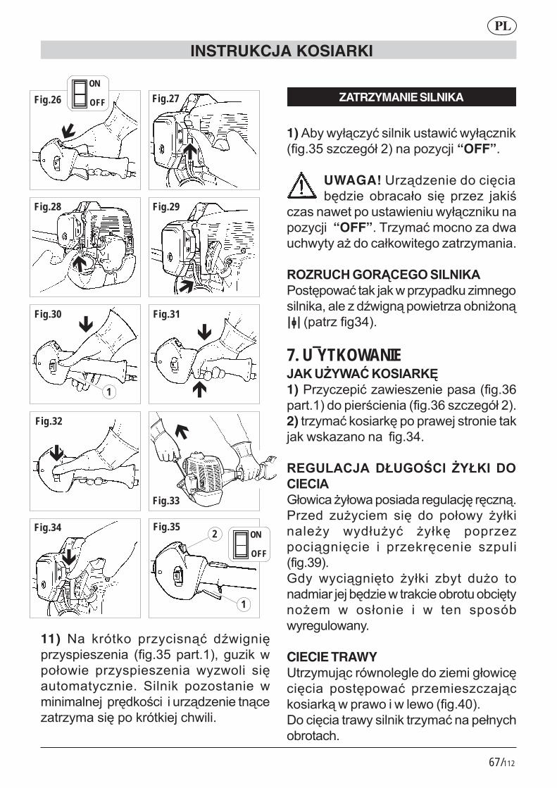
67/112
11)� =�� +*9,+�� *� ����.:� )B(�/��4*� ���������� �8�/5�@��*,5?!�� /���+�(�1�(��� *� ���������� ( �(���� ��4��,�0�, �����5� �����+� ����,����� (0���0������*4)+�'�������*�.)������,�.����,*� 0����4���+*9,+����7(���5
Fig.27
Fig.28 Fig.29
Fig.30 Fig.31
Fig.32
Fig.33
Fig.34 Fig.35
�
�
�
�
�
�
� �
�
1
2
1
Fig.26
�
ON
OFF
ON
OFF
ZATRZYMANIE SILNIKA
1)��2 �( 1.�� :������+���,�(�:�( 1.����+�8�/5�@������/91��!������ ���“OFF”.
UWAGA!�>*�.)������)����4���24)���� �2*���1�� ��4� *���� �+�'
�������(�,�����,�(������( 1.����+������ ����“OFF”5�D*� 0�:�0��������)(���7( , ����)����1+�(�,�/����,*� 0����5
�%#�0�N�$%�O��$%�* ,' !"<��,4�(�:�,�+��+�(�*� �)+����0��/������+���������)B(�/�.��(��,*����2�����.�������,*��8�/�M!5
7. U¯YTKOWANIE3"!�07�2"8�!%* "�!41)�<*� ����:���(��������������8�/5���*,5?!�)����*'��������8�/5��������/91��!52) ,*� 0�:�+����*+4���*�(���,*�����,�+�+�(�+����������8�/5�M5
��$0,"�3"� &10$%(� � 7�1! � &%� �� ";1�(����� 1�(������)��*�/����4�*4���.5<*��)� ��� ���0� ��4� )�� �1�( � � 1+������ � ( )1�� :� � 1+4� �*������./��4���� �� *��+*4������ ������8�/5�N!5;) � ( ��./��4,�� � 1+�� �2 ,� )���� ,���)0��*���24)����(�,*�+�����2*�,���2��4, ����0� (� ��1����� �� (� ,��� ���92( *�/���(�� 5
CIECIE TRAWY>,*� 0�.��*9(����/���)�����0��/1�(��4��4���� ��,4�(�:� *��0�������.�+����*+.�(�*�(����(���(���8�/5M�!5I����4����,*�( ������+�,*� 0�:�����1� �7�2*�,��75
INSTRUKCJA KOSIARKI
PL

68/112
CIECIE DOOKO1"� ��#�*#!P&C&�#�2C�#"$�P&L�++�� )�,+�.:� *����+�)4� +�6�9(+.� 1+���8�/5M�!5�<*� �7 ������/1�(�� ��8�/5M?!0��������� :��8�+,���4���5�=����)�*��:��*����+�) �/1�(��.���4������ 0�0������(�)�(�:���1+�(�,�����*(������ 1�+5"�*� �)+���)�*(�������4�� 1+������� ��,4�(�:�,�+��+�*� �( 0�����5
Q��2�) "'"�7�1! �2 ���(��.:���(.�� 14�����* /�����������5A) �,���(�:�� 1+4����,�+�(.���'*�)��� ��00��)�(��)��.�)����4����,*�( 5
02"$"�' �+�#� ��#�5*�2%<2�7"&'�)���#��"&!0�' �07�2"8�7�1! �*�",%2�32�) "'4�2�!%'"8���#�2�1O�#%'�)�* ,' !0�
+L�&�)%'�"7�*#�0, 1)� �)+*4��:� (� +��*��+�� �/�)� 0� �*��7�0� (�+��9(�+� ��/�*�� ��+*4,+4�8�/5M�!52)�R��./�.:�����4���8�/5M�EMMEM@!53)�I�+1�)����( �� '��:�(�4,*���/1�(�� �8�/5M�!�5
�L�'"2 3"' ��7�1! 1)� <*� /�,�(�:� )(�� �)���+�� � 1+�� ���)1�������)���052)�3�6�9(+��(1�� :�)���)�(��)���7���,(�*9(��8�/5M�!53) <�*4�+�(�1+9(�� 1+����(��.:��������4�/�)������+��*��+��0��,*��1+�����������8�/5MF!54)� �2 � �1�,(�:� ��+1�)����� ������ (+�*�����*� 0���(�:�)(���+�6�9(+��)��)�(��)���7�( �1�2��6��8�/5MN!5
&L��%'%2'��)%'�"7�*#�0, 1) "1�� :�)(���+�6�9(+��*�����,(�* �8�/5@�!5
2)�C�1�� :�����4������./�.:�0�����)(��+�6�9(+�� ,�+� �2 � ( ��1 � �� ( �1�2��6�8�/5@?!53)�>�,�(�:��*4� �4��8�/5@�!���*� +*4��:��+*4,+4�(�+��*��+��przeciwnym od ruchuwskazówek zegara (fig.53).
9. CZYNNOŒCI KONSERWACYJNE(2 ��"<*� ��0����*���(�*�+���2�(�*� �)+�,*�)��'���*��*��7����*�()��:��,���'(��� ��1���(�5<*��)� ( 0���.� �)���+�:� (� ������71�)�����������+�51) R��./�.:��+* (+4����)+*4��:�'(���4)��,�*���� 0���+����*+.�+�����0��8�/5@M!5"� *� �)+�� ��)0��*��� �+�*� � ��2�������/�� ��� ���� ���+,*�)� ����� '(���4�( 0����:������(.�,�/����0�/�, ���8�/5@@E@�!5=�)0��*� �+�*� � 0���� 2 :��(�)�(�� -#��2 ,�)��.����'��.������(�0�����������2���(1�'��(.��+�'��.������5# zatkanym ��4'���(��8��,*�0��(��,*��52)��4������*� +*4��:�'(���4�)��+�6��/(��,�� �� �(���:��2 ��������+�)��:� ��2��) 5� 3����� ( +�*� �,�:� � , �+�� )�+�6��(�/��)�+*4��������8�/5@M!5
FILTR POWIETRZA$���+�'�������� '��:�8��,*��(��,*��5�J��,*�� '��:����4'������eli kosiarka pracujew strefach zakurzonych.1)��)+*4��:�'*�24��+* ( ��8�/5@�!52) � :�(�).���2����,*��� 0�)�,�*/��,�053)�<*��)���1������0�8��,*������ �( ���� :�8�/5@F!52��������J�=���>������� ����������F�������H����������B����=�����
� ,����1�WAKOWY BENZYNYJ��,*�( 0����:� *���(� *�+�5�"� , 0���������� � ( ��./�.:� /�� 7�+��0� �*���(��(��2��*��+�5
INSTRUKCJA KOSIARKI
PL

69/112
* "�!"�#"+�#� ��#"3O�"��10) !"# "� *�*��� ( )��7�(�� ��1���� � ��,��*'���6� �� ���,+.� ���4':� ��2�*)���( �,�.��!5# ���,+���( +�����, +����4��/*������.����������( )���':������+�#�" ��./�.:���*'���6������,+.�����,.�8�/5M?!5
MINIMALNE OBROTY SILNIKA#�=���� ��*�()��:�(�,*�+���+��)�/�� �� ,+�(����� �2
�*�.)������,�.��������2*���1����4�*� 0���0��� �7��2*�,��7������+�5# W przypadku obracan��� ��4� ��,*������� ��/1���:���4�)�����,*�0��2�1�/��(�����*�/�����5!%'��%,"� (�0+� � �#4(� %+�%�%2��N# <*��)� +��) 0� �� ,+�(����0�*�()��:� �,��� *� +*4������ '*�2� ������(�������4'��5��*�()��:���2 ����2 1��4+��4:� ��2��������/����� ����(�*�.)������,�.� 05# " 0����:� ��4'��� ��� ,�� *��)�� ,+�(����05
CZYSZCZENIE I KONSERWACJA# "�*� �)+��/) �+����*+������24)����� (����*�������)���0����.��������� �*9���:��2��*��+���2��� � 5#�=����� '��:��/*�� (� 0��1 ��0�5#� <*���7�( (�:� �*�.)������ (�0��������������7 0���2������� 0���)���+���)�����4/��)�����5# I��,*����*,������� ��*9���:��2��*��+��2��� � �����2������ :���,*����/) ���,��0��,�(���!� (1�'��( 0��2����������05
INSTRUKCJA KOSIARKI
PL
___________________________________________________________________________________________________________________________________________________________________________________________________________________________________________________________________________________________________________________________________________________________________________________________________________________________________________________________________________________________________________________________________________________________________________________________________________________________________________________________________________________________________________________________________________________________________________________________________________________________________________________________________________________________________________________________________________________________________________________________________________________________________________________________________________________________________________________________________________________________________________________________

70/112
INSTRUKCJA KOSIARKI
PL
DANE TECHNICZNE GBL 26
$�4��* 4,8 kg
���2������(��S��*�.)������)����4����S���2����������!
��<��0��':��2��*��+���������������������������700 cm³
��C��91�)����4�����/1�(����� 1�(�! 420 mm
� �>*�.)������ ,�.��� ���,*��! 230 mm��<��0��':������+� 25,5 cm³
Moc maksymalna 0,75 kW
����+� 0������2*�, �/1�(�� �� 1�(��� 9.500 1/min
Maks 0������2*�, ����*�.)��������4��� 7.500 1/min
Minimalne obroty 2.800 1/min
��<����0���'��������+��, ����/��� 98 dB(A)
LpA av (EN 7917)
Poziom mocy akustycznej 108 dB(A)
LwA av (ISO 10884)
Maksymalny poziom wibracji 9,9 m/s²
(ISO 7916)
Maksymalny poziom wibracji ostrza 10,6 m/s²
(ISO 7916)
DANE TECHNICZNE GB 26
$�4��* 4,9 kg
���2������(��S��*�.)������)����4����S���2����������!
��<��0��':��2��*��+���������������������������700 cm³
��C��91�)����4�����/1�(����� 1�(�! 420 mm
� �>*�.)������ ,�.��� ���,*��! 230 mm��<��0��':������+� 25,5 cm³
Moc maksymalna 0,75 kW
����+� 0������2*�, �/1�(�� �� 1�(��� 9.500 1/min
Maks 0������2*�, ����*�.)��������4��� 7.500 1/min
Minimalne obroty 2.800 1/min
��<����0���'��������+��, ����/��� 98 dB(A)
LpA av (EN 7917)
Poziom mocy akustycznej 108 dB(A)
LwA av (ISO 10884)
Maksymalny poziom wibracji 9,6 m/s²
(ISO 7916)
Maksymalny poziom wibracji ostrza 10,4 m/s²
(ISO 7916)
____________________________________________________________________________________________________________________________________________________________________________________________________________________________________________________________________________________________________________________________________________________________________________________________________________________________________________________________________________________________________________________
____________________________________________________________________________________________________________________________________________________________________________________________________________________________________________________________________________________________________________________________________________________________________________________________________________________________________________________________________________________________________________________

71/112
INSTRUKCJA KOSIARKI
PL
____________________________________________________________________________________________________________________________________________________________________________________________________________________________________________________________________________________________________________________________________________________________________________________________________________________________________________________________________________________________________________________
____________________________________________________________________________________________________________________________________________________________________________________________________________________________________________________________________________________________________________________________________________________________________________________________________________________________________________________________________________________________________________________
DANE TECHNICZNE GBL 34
$�4��* @CR kg
���2������(��S��*�.)������)����4����S���2����������!
��<��0��':��2��*��+���������������������������830 cm³
��C��91�)����4�����/1�(����� 1�(�! 420 mm
� �>*�.)������ ,�.������,*��! 230 mm
��<��0��':������+� 33,6 cm³
Moc maksymalna 1 kW
����+� 0������2*�, �/1�(�� �� 1�(��� 9.500 1/min
Maks 0������2*�, ����*�.)��������4��� 7.500 1/min
Minimalne obroty 2.800 1/min
��<����0���'��������+��, ����/��� 97 dB(A)
LpA av (EN 7917)
Poziom mocy akustycznej 107 dB(A)
LwA av (ISO 10884)
Maksymalny poziom wibracji 8 m/s²
(ISO 7916)
Maksymalny poziom wibracji ostrza 8,9 m/s²
(ISO 7916)
DANE TECHNICZNE GB 34
$�4��* 6,0 kg
���2������(��S��*�.)������)����4����S���2����������!
��<��0��':��2��*��+���������������������������830 cm³
��C��91�)����4�����/1�(����� 1�(�! 420 mm
� �>*�.)������ ,�.������,*��! 230 mm
��<��0��':������+� 33,6 cm³
Moc maksymalna 1 kW
����+� 0������2*�, �/1�(�� �� 1�(��� 9.500 1/min
Maks 0������2*�, ����*�.)��������4��� 7.500 1/min
Minimalne obroty 2.800 1/min
��<����0���'��������+��, ����/��� 97 dB(A)
LpA av (EN 7917)
Poziom mocy akustycznej 107 dB(A)
LwA av (ISO 10884)
Maksymalny poziom wibracji 5,6 m/s²
(ISO 7916)
Maksymalny poziom wibracji ostrza 6,2 m/s²
(ISO 7916)

72/112
La SANDRIGARDEN si riserva il diritto di apportare modifiche sia tecniche che estetiche al prodotto e al presente manuale senza preavviso.
SANDRIGARDEN reserves the right to makeany technical or stylistic modifications to the product or this manual without prior no.
Die Fa. SANDRIGARDEN behält sich das Recht vor, jederzeit und ohne Vorankündigungtechnische und ästhetische Änderungen an Ihren Produkten vorzunehmen.
SANDRIGARDEN se réserve le droit d’apporter toute modification technique ou esthétique sans avertir au préalable.
De firma SANDRIGARDEN behoudt zich het recht voor onaangekondigd zoweltechnische wijzigingen als esthetische veranderingen aan te brengen.
SANDRIGARDEN s.r.l. se reserva el derecho de hacer modificacionestécnicas y estéticas sin aviso previo.
A Sandrigarden s.r.l. reserva-se o direito de produzir modificaçõesquer técnicas quer estéticas sem aviso prévio.
Sandrigarden z o.o. rezerwuje sobie do wprowadzania zmiana
technicznych jak i estetycznych bez uprzedzenia.
Sede legale: via Manzoni, 22 - 36027 - ROSÀ (VI) - ITALIAUffici: via Verdi, 13 - 23847 - MOLTENO (LC) - ITALIA Tel. 031/3570411 - Fax.031/35704435

73/112
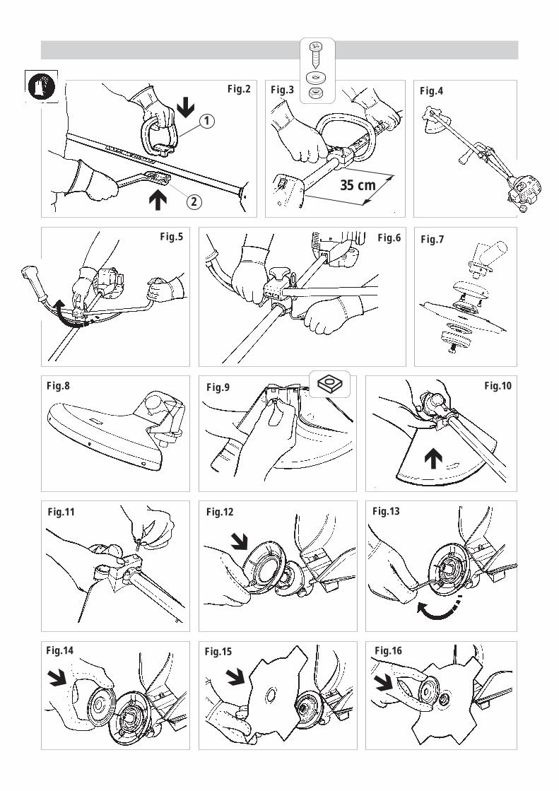
74/112
Fig.2 Fig.3 Fig.4
Fig.5 Fig.6
Fig.8 Fig.9 Fig.10
Fig.7
Fig.11 Fig.12 Fig.13
Fig.15 Fig.16
1
235 cm
�
�
�
�
Fig.14
� � �

75/112
Fig.17 Fig.18 Fig.19
Fig.20 Fig.21
Fig.22
1
Fig.23 Fig.24
Fig.39
�
�
1
2
�
1
2
Fig.36
�
Fig.38Fig.37
�
1 2
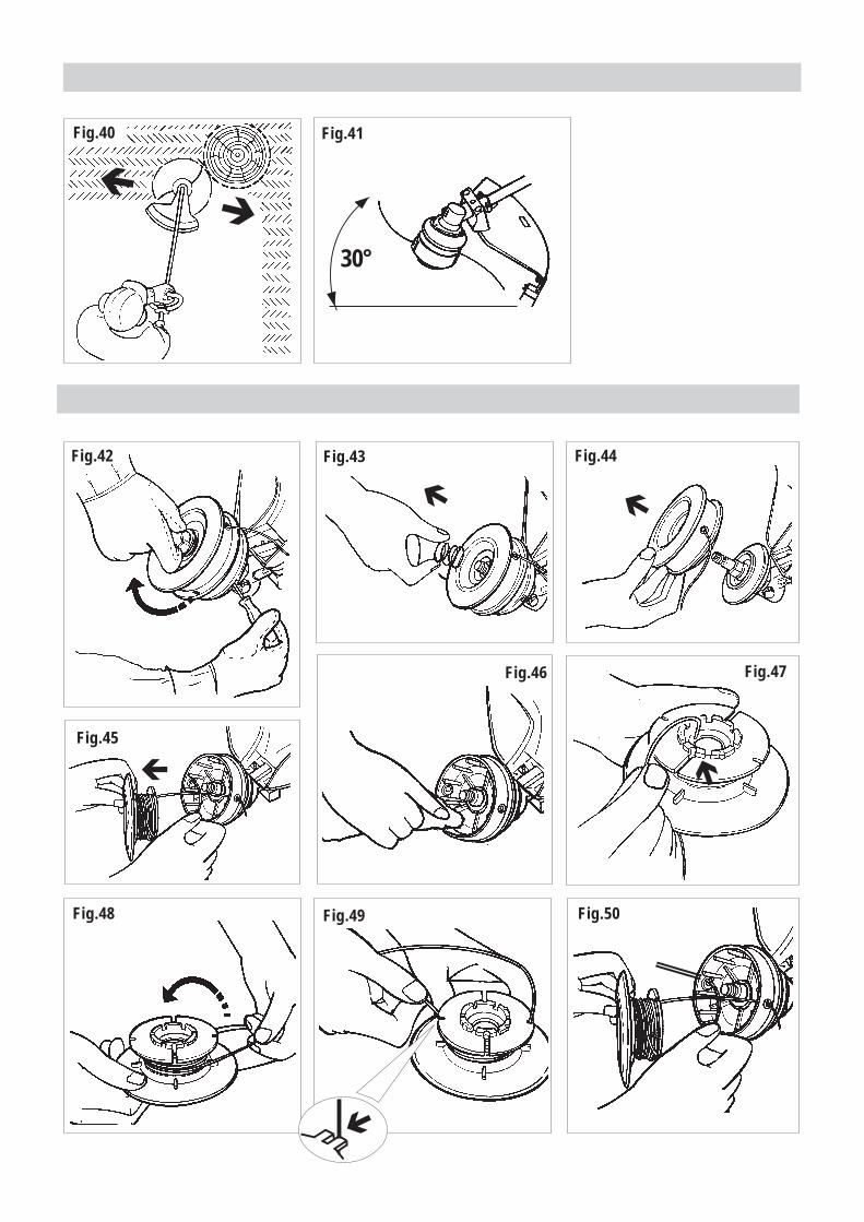
76/112
Fig.42 Fig.43 Fig.44
Fig.46
Fig.50
Fig.47
Fig.48 Fig.49
Fig.40� �
30°
Fig.41
Fig.45
� �
� �
�

77/112
Fig.51 Fig.52
Fig.55 Fig.56
Fig.57 Fig.58
Fig.59
Fig.54
�
�
0,5
- 0,6
mm
�
�
�
� �
Fig.53