Experiences with Slot Radiography Using SONIALVISION safire17 · Experiences with Slot Radiography...
5
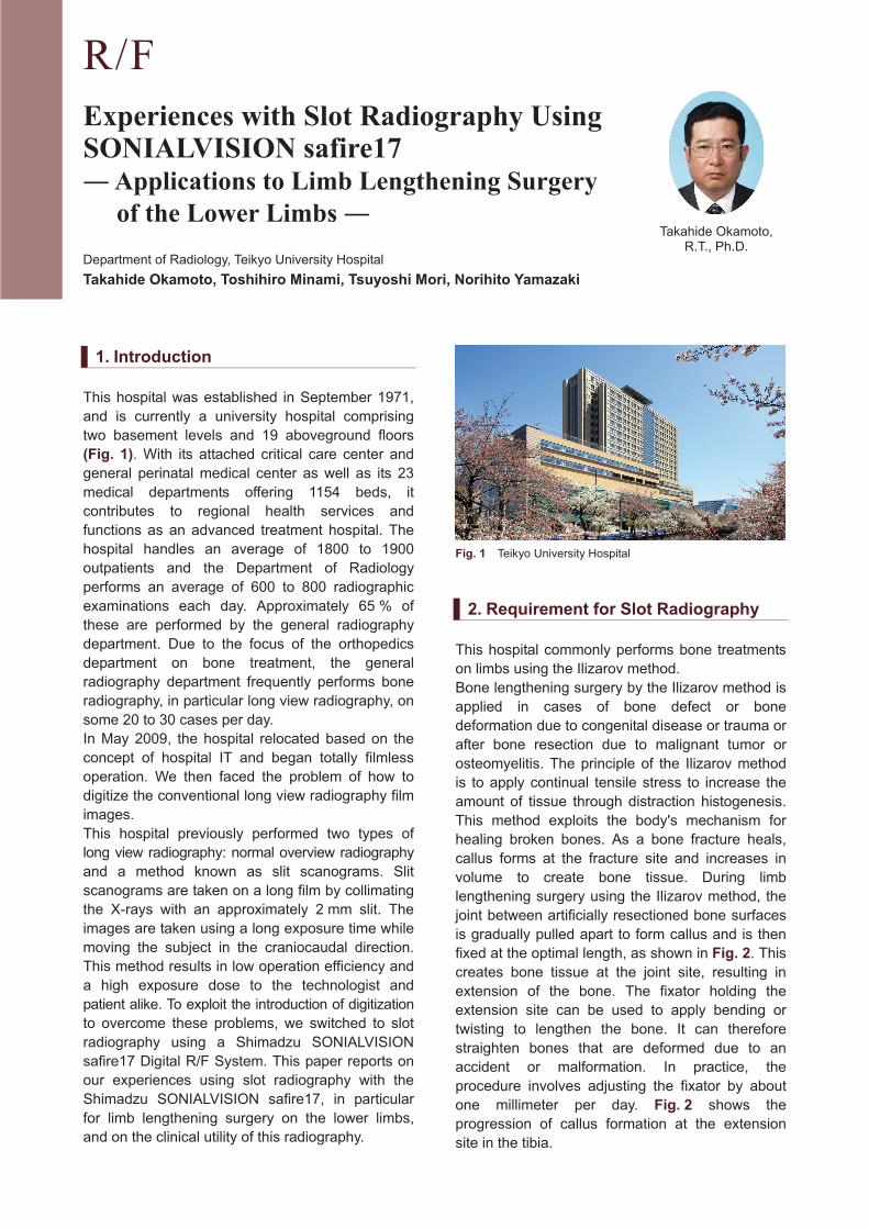
R/F Experiences with Slot Radiography Using SONIALVISION safire17 Applications to Limb Lengthening Surgery of the Lower Limbs Department of Radiology, Teikyo University Hospital Takahide Okamoto, Toshihiro Minami, Tsuyoshi Mori, Norihito Yamazaki Takahide Okamoto, R.T., Ph.D. 1. Introduction This hospital was established in September 1971, and is currently a university hospital comprising two basement levels and 19 aboveground floors (Fig. 1). With its attached critical care center and general perinatal medical center as well as its 23 medical departments offering 1154 beds, it contributes to regional health services and functions as an advanced treatment hospital. The hospital handles an average of 1800 to 1900 outpatients and the Department of Radiology performs an average of 600 to 800 radiographic examinations each day. Approximately 65 % of these are performed by the general radiography department. Due to the focus of the orthopedics department on bone treatment, the general radiography department frequently performs bone radiography, in particular long view radiography, on some 20 to 30 cases per day. In May 2009, the hospital relocated based on the concept of hospital IT and began totally filmless operation. We then faced the problem of how to digitize the conventional long view radiography film images. This hospital previously performed two types of long view radiography: normal overview radiography and a method known as slit scanograms. Slit scanograms are taken on a long film by collimating the X-rays with an approximately 2 mm slit. The images are taken using a long exposure time while moving the subject in the craniocaudal direction. This method results in low operation efficiency and a high exposure dose to the technologist and patient alike. To exploit the introduction of digitization to overcome these problems, we switched to slot radiography using a Shimadzu SONIALVISION safire17 Digital R/F System. This paper reports on our experiences using slot radiography with the Shimadzu SONIALVISION safire17, in particular for limb lengthening surgery on the lower limbs, and on the clinical utility of this radiography. Fig. 1 Teikyo University Hospital 2. Requirement for Slot Radiography This hospital commonly performs bone treatments on limbs using the Ilizarov method. Bone lengthening surgery by the Ilizarov method is applied in cases of bone defect or bone deformation due to congenital disease or trauma or after bone resection due to malignant tumor or osteomyelitis. The principle of the Ilizarov method is to apply continual tensile stress to increase the amount of tissue through distraction histogenesis. This method exploits the body's mechanism for healing broken bones. As a bone fracture heals, callus forms at the fracture site and increases in volume to create bone tissue. During limb lengthening surgery using the Ilizarov method, the joint between artificially resectioned bone surfaces is gradually pulled apart to form callus and is then fixed at the optimal length, as shown in Fig. 2. This creates bone tissue at the joint site, resulting in extension of the bone. The fixator holding the extension site can be used to apply bending or twisting to lengthen the bone. It can therefore straighten bones that are deformed due to an accident or malformation. In practice, the procedure involves adjusting the fixator by about one millimeter per day. Fig. 2 shows the progression of callus formation at the extension site in the tibia.
Transcript of Experiences with Slot Radiography Using SONIALVISION safire17 · Experiences with Slot Radiography...
R/F
Experiences with Slot Radiography Using SONIALVISION safire17 ! Applications to Limb Lengthening Surgery
of the Lower Limbs !
Department of Radiology, Teikyo University Hospital
Takahide Okamoto, Toshihiro Minami, Tsuyoshi Mori, Norihito Yamazaki
Takahide Okamoto, R.T., Ph.D.
1. Introduction
This hospital was established in September 1971,
and is currently a university hospital comprising
two basement levels and 19 aboveground floors
(Fig. 1). With its attached critical care center and
general perinatal medical center as well as its 23
medical departments offering 1154 beds, it
contributes to regional health services and
functions as an advanced treatment hospital. The
hospital handles an average of 1800 to 1900
outpatients and the Department of Radiology
performs an average of 600 to 800 radiographic
examinations each day. Approximately 65 % of
these are performed by the general radiography
department. Due to the focus of the orthopedics
department on bone treatment, the general
radiography department frequently performs bone
radiography, in particular long view radiography, on
some 20 to 30 cases per day.
In May 2009, the hospital relocated based on the
concept of hospital IT and began totally filmless
operation. We then faced the problem of how to
digitize the conventional long view radiography film
images.
This hospital previously performed two types of
long view radiography: normal overview radiography
and a method known as slit scanograms. Slit
scanograms are taken on a long film by collimating
the X-rays with an approximately 2 mm slit. The
images are taken using a long exposure time while
moving the subject in the craniocaudal direction.
This method results in low operation efficiency and
a high exposure dose to the technologist and
patient alike. To exploit the introduction of digitization
to overcome these problems, we switched to slot
radiography using a Shimadzu SONIALVISION
safire17 Digital R/F System. This paper reports on
our experiences using slot radiography with the
Shimadzu SONIALVISION safire17, in particular
for limb lengthening surgery on the lower limbs,
and on the clinical utility of this radiography.
Fig. 1 Teikyo University Hospital
2. Requirement for Slot Radiography
This hospital commonly performs bone treatments
on limbs using the Ilizarov method.
Bone lengthening surgery by the Ilizarov method is
applied in cases of bone defect or bone
deformation due to congenital disease or trauma or
after bone resection due to malignant tumor or
osteomyelitis. The principle of the Ilizarov method
is to apply continual tensile stress to increase the
amount of tissue through distraction histogenesis.
This method exploits the body's mechanism for
healing broken bones. As a bone fracture heals,
callus forms at the fracture site and increases in
volume to create bone tissue. During limb
lengthening surgery using the Ilizarov method, the
joint between artificially resectioned bone surfaces
is gradually pulled apart to form callus and is then
fixed at the optimal length, as shown in Fig. 2. This
creates bone tissue at the joint site, resulting in
extension of the bone. The fixator holding the
extension site can be used to apply bending or
twisting to lengthen the bone. It can therefore
straighten bones that are deformed due to an
accident or malformation. In practice, the
procedure involves adjusting the fixator by about
one millimeter per day. Fig. 2 shows the
progression of callus formation at the extension
site in the tibia.
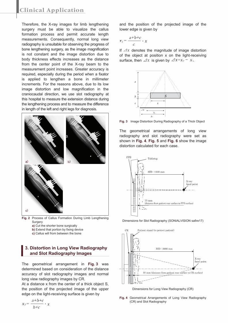
Therefore, the X-ray images for limb lengthening
surgery must be able to visualize the callus
formation process and permit accurate length
measurements. Consequently, normal long view
radiography is unsuitable for observing the progress of
bone lengthening surgery, as the image magnification
is not constant and the image distortion due to
body thickness effects increases as the distance
from the center point of the X-ray beam to the
measurement point increases. Greater accuracy is
required, especially during the period when a fixator
is applied to lengthen a bone in millimeter
increments. For the reasons above, due to its low
image distortion and low magnification in the
craniocaudal direction, we use slot radiography at
this hospital to measure the extension distance during
the lengthening process and to measure the difference
in length of the left and right legs for diagnosis.
Fig. 2 Process of Callus Formation During Limb Lengthening
Surgery
a) Cut the shorter bone surgically
b) Extend that portion by fixing device
c) Callus will from between the bone
3. Distortion in Long View Radiography
and Slot Radiography Images
The geometrical arrangement in Fig. 3 was
determined based on consideration of the distance
accuracy of slot radiography images and normal
long view radiography images by CR.
At a distance x from the center of a thick object S,
the position of the projected image of the upper
edge on the light-receiving surface is given by
and the position of the projected image of the
lower edge is given by
If denotes the magnitude of image distortion
of the object at position x on the light-receiving
surface, then is given by .
Fig. 3 Image Distortion During Radiography of a Thick Object
The geometrical arrangements of long view
radiography and slot radiography were set as
shown in Fig. 4. Fig. 5 and Fig. 6 show the image
distortion calculated for each case.
Dimensions for Slot Radiography (SONIALVISION safire17)
Dimensions for Long View Radiography (CR)
Fig. 4 Geometrical Arrangements of Long View Radiography
(CR) and Slot Radiography
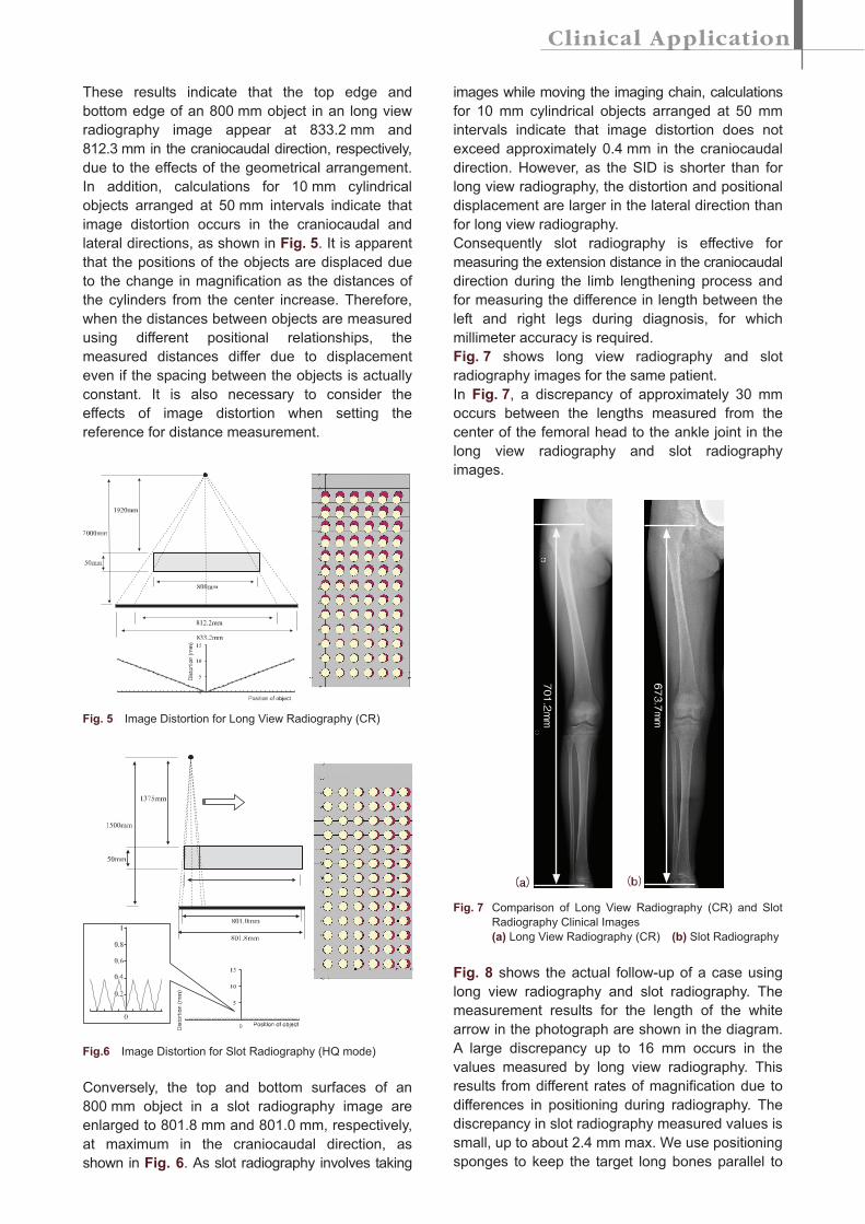
These results indicate that the top edge and
bottom edge of an 800 mm object in an long view
radiography image appear at 833.2 mm and
812.3 mm in the craniocaudal direction, respectively,
due to the effects of the geometrical arrangement.
In addition, calculations for 10 mm cylindrical
objects arranged at 50 mm intervals indicate that
image distortion occurs in the craniocaudal and
lateral directions, as shown in Fig. 5. It is apparent
that the positions of the objects are displaced due
to the change in magnification as the distances of
the cylinders from the center increase. Therefore,
when the distances between objects are measured
using different positional relationships, the
measured distances differ due to displacement
even if the spacing between the objects is actually
constant. It is also necessary to consider the
effects of image distortion when setting the
reference for distance measurement.
Fig. 5 Image Distortion for Long View Radiography (CR)
Fig.6 Image Distortion for Slot Radiography (HQ mode)
Conversely, the top and bottom surfaces of an
800 mm object in a slot radiography image are
enlarged to 801.8 mm and 801.0 mm, respectively,
at maximum in the craniocaudal direction, as
shown in Fig. 6. As slot radiography involves taking
images while moving the imaging chain, calculations
for 10 mm cylindrical objects arranged at 50 mm
intervals indicate that image distortion does not
exceed approximately 0.4 mm in the craniocaudal
direction. However, as the SID is shorter than for
long view radiography, the distortion and positional
displacement are larger in the lateral direction than
for long view radiography.
Consequently slot radiography is effective for
measuring the extension distance in the craniocaudal
direction during the limb lengthening process and
for measuring the difference in length between the
left and right legs during diagnosis, for which
millimeter accuracy is required.
Fig. 7 shows long view radiography and slot
radiography images for the same patient.
In Fig. 7, a discrepancy of approximately 30 mm
occurs between the lengths measured from the
center of the femoral head to the ankle joint in the
long view radiography and slot radiography
images.
Fig. 7 Comparison of Long View Radiography (CR) and Slot
Radiography Clinical Images
(a) Long View Radiography (CR) (b) Slot Radiography
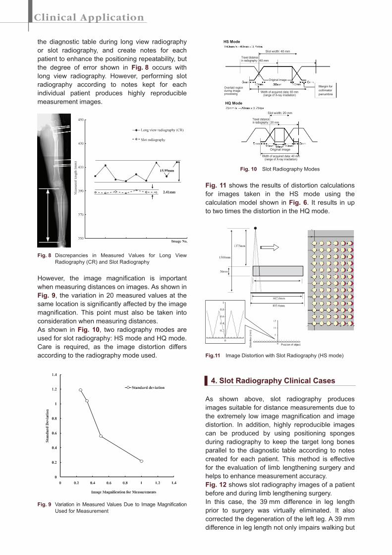
Fig. 8 shows the actual follow-up of a case using
long view radiography and slot radiography. The
measurement results for the length of the white
arrow in the photograph are shown in the diagram.
A large discrepancy up to 16 mm occurs in the
values measured by long view radiography. This
results from different rates of magnification due to
differences in positioning during radiography. The
discrepancy in slot radiography measured values is
small, up to about 2.4 mm max. We use positioning
sponges to keep the target long bones parallel to
the diagnostic table during long view radiography
or slot radiography, and create notes for each
patient to enhance the positioning repeatability, but
the degree of error shown in Fig. 8 occurs with
long view radiography. However, performing slot
radiography according to notes kept for each
individual patient produces highly reproducible
measurement images.
Fig. 8 Discrepancies in Measured Values for Long View
Radiography (CR) and Slot Radiography
However, the image magnification is important
when measuring distances on images. As shown in
Fig. 9, the variation in 20 measured values at the
same location is significantly affected by the image
magnification. This point must also be taken into
consideration when measuring distances.
As shown in Fig. 10, two radiography modes are
used for slot radiography: HS mode and HQ mode.
Care is required, as the image distortion differs
according to the radiography mode used.
Fig. 9 Variation in Measured Values Due to Image Magnification
Used for Measurement
Fig. 10 Slot Radiography Modes
Fig. 11 shows the results of distortion calculations
for images taken in the HS mode using the
calculation model shown in Fig. 6. It results in up
to two times the distortion in the HQ mode.
Fig.11 Image Distortion with Slot Radiography (HS mode)
4. Slot Radiography Clinical Cases
As shown above, slot radiography produces
images suitable for distance measurements due to
the extremely low image magnification and image
distortion. In addition, highly reproducible images
can be produced by using positioning sponges
during radiography to keep the target long bones
parallel to the diagnostic table according to notes
created for each patient. This method is effective
for the evaluation of limb lengthening surgery and
helps to enhance measurement accuracy.
Fig. 12 shows slot radiography images of a patient
before and during limb lengthening surgery.
In this case, the 39 mm difference in leg length
prior to surgery was virtually eliminated. It also
corrected the degeneration of the left leg. A 39 mm
difference in leg length not only impairs walking but
HS Mode
HQ Mode
Slot width: 40 mm
Slot width: 20 mm
Width of acquired data: 40 mm(range of X-ray irradiation)
Original image
Width of acquired data: 60 mm(range of X-ray irradiation)
Overlaid regionduring imageprocessing
Margin for
collimator
penumbra
Original image
Travel distancein radiography: 40 mm
Travel distancein radiography: 20 mm
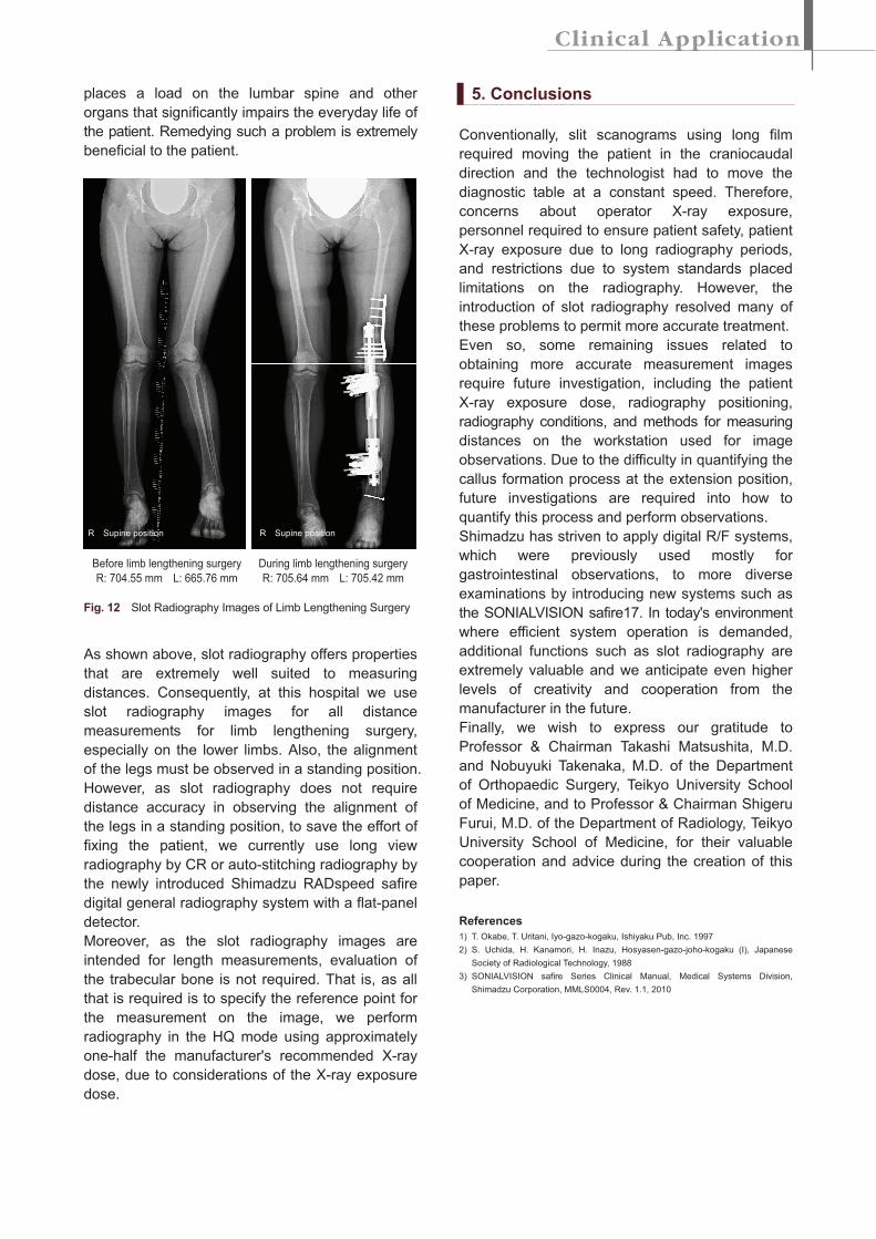
places a load on the lumbar spine and other
organs that significantly impairs the everyday life of
the patient. Remedying such a problem is extremely
beneficial to the patient.
Before limb lengthening surgery
R: 704.55 mm L: 665.76 mm
During limb lengthening surgery
R: 705.64 mm L: 705.42 mm
Fig. 12 Slot Radiography Images of Limb Lengthening Surgery
As shown above, slot radiography offers properties
that are extremely well suited to measuring
distances. Consequently, at this hospital we use
slot radiography images for all distance
measurements for limb lengthening surgery,
especially on the lower limbs. Also, the alignment
of the legs must be observed in a standing position.
However, as slot radiography does not require
distance accuracy in observing the alignment of
the legs in a standing position, to save the effort of
fixing the patient, we currently use long view
radiography by CR or auto-stitching radiography by
the newly introduced Shimadzu RADspeed safire
digital general radiography system with a flat-panel
detector.
Moreover, as the slot radiography images are
intended for length measurements, evaluation of
the trabecular bone is not required. That is, as all
that is required is to specify the reference point for
the measurement on the image, we perform
radiography in the HQ mode using approximately
one-half the manufacturer's recommended X-ray
dose, due to considerations of the X-ray exposure
dose.
5. Conclusions
Conventionally, slit scanograms using long film
required moving the patient in the craniocaudal
direction and the technologist had to move the
diagnostic table at a constant speed. Therefore,
concerns about operator X-ray exposure,
personnel required to ensure patient safety, patient
X-ray exposure due to long radiography periods,
and restrictions due to system standards placed
limitations on the radiography. However, the
introduction of slot radiography resolved many of
these problems to permit more accurate treatment.
Even so, some remaining issues related to
obtaining more accurate measurement images
require future investigation, including the patient
X-ray exposure dose, radiography positioning,
radiography conditions, and methods for measuring
distances on the workstation used for image
observations. Due to the difficulty in quantifying the
callus formation process at the extension position,
future investigations are required into how to
quantify this process and perform observations.
Shimadzu has striven to apply digital R/F systems,
which were previously used mostly for
gastrointestinal observations, to more diverse
examinations by introducing new systems such as
the SONIALVISION safire17. In today's environment
where efficient system operation is demanded,
additional functions such as slot radiography are
extremely valuable and we anticipate even higher
levels of creativity and cooperation from the
manufacturer in the future.
Finally, we wish to express our gratitude to
Professor & Chairman Takashi Matsushita, M.D.
and Nobuyuki Takenaka, M.D. of the Department
of Orthopaedic Surgery, Teikyo University School
of Medicine, and to Professor & Chairman Shigeru
Furui, M.D. of the Department of Radiology, Teikyo
University School of Medicine, for their valuable
cooperation and advice during the creation of this
paper.
References
1) T. Okabe, T. Uritani, Iyo-gazo-kogaku, Ishiyaku Pub, Inc. 1997
2) S. Uchida, H. Kanamori, H. Inazu, Hosyasen-gazo-joho-kogaku (I), Japanese
Society of Radiological Technology, 1988
3) SONIALVISION safire Series Clinical Manual, Medical Systems Division,
Shimadzu Corporation, MMLS0004, Rev. 1.1, 2010
R Supine position R Supine position