Evaluation of Drilling Rig Performance...
39
Evaluation of Drilling Rig Performance Characteristics Quinton T. Foulston, P.Eng. Precision Drilling CADE/CAODC 2009 Annual Drilling Conference 1
Transcript of Evaluation of Drilling Rig Performance...
Evaluation of Drilling Rig Performance Characteristics
Quinton T. Foulston, P.Eng. Precision Drilling
CADE/CAODC 2009 Annual Drilling Conference
1
2
1. Explore some of the ambiguities around the traditional RIG DEPTH RATING
2. Describe four (4) ALTERNATE drilling rig performance CHARACTERISTICS
3. Conclude with a brief summary
I will:
3
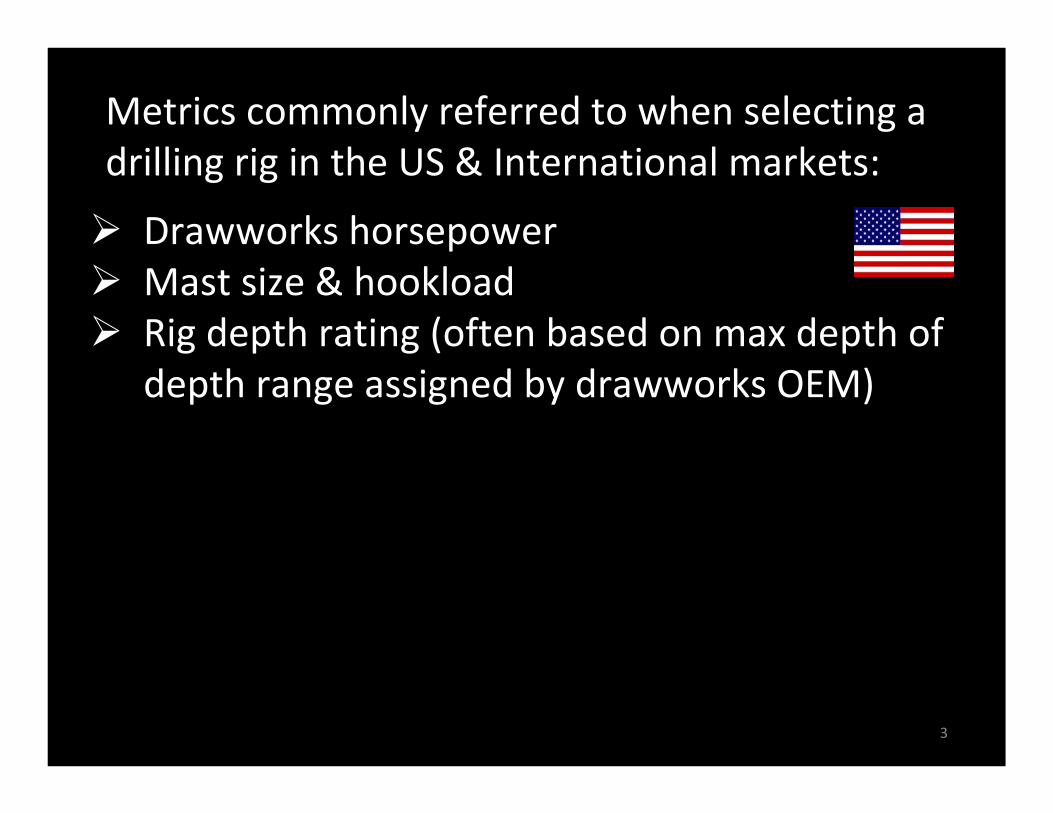
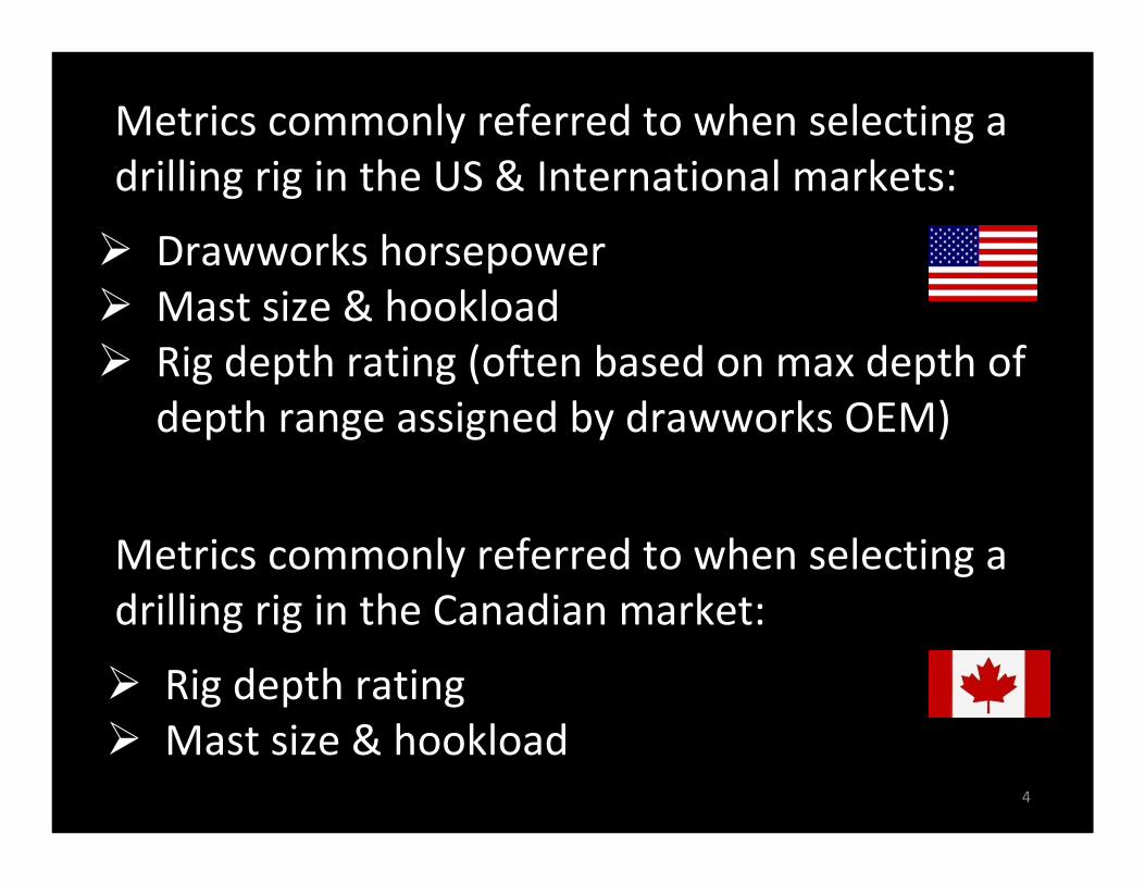
Metrics commonly referred to when selecting a drilling rig in the US & International markets:
Drawworks horsepowerMast size & hookloadRig depth rating (often based on max depth of depth range assigned by drawworks OEM)
4
Metrics commonly referred to when selecting a drilling rig in the US & International markets:
Drawworks horsepowerMast size & hookloadRig depth rating (often based on max depth of depth range assigned by drawworks OEM)
Rig depth ratingMast size & hookload
Metrics commonly referred to when selecting a drilling rig in the Canadian market:
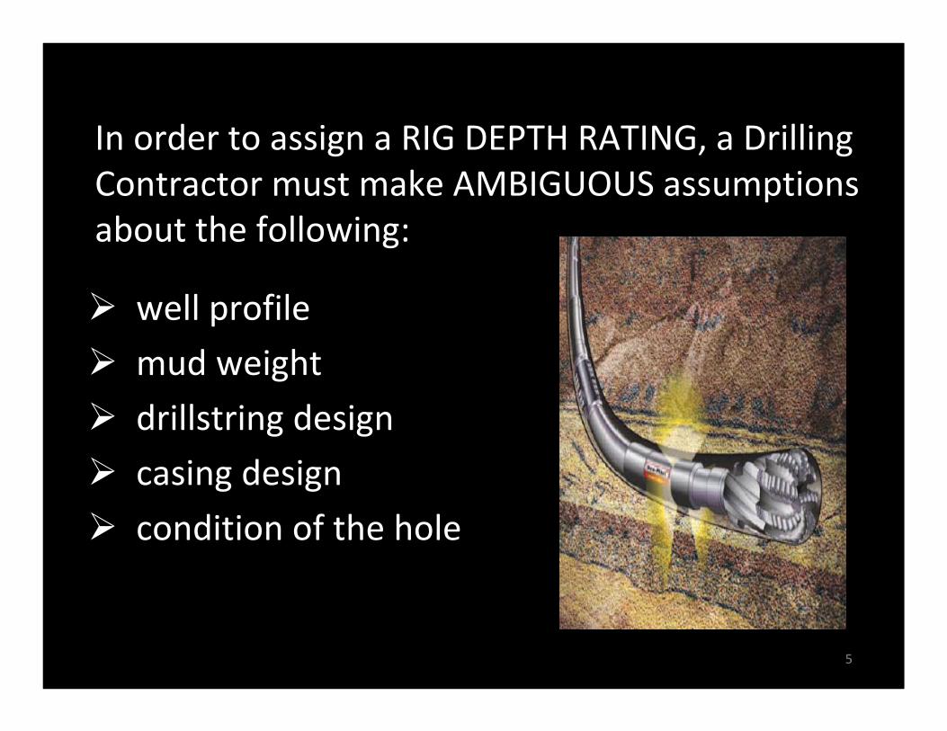
well profile
mud weight
drillstring design
casing design
condition of the hole
In order to assign a RIG DEPTH RATING, a Drilling Contractor must make AMBIGUOUS assumptions about the following:
5
What can the rig PULL?
1. when stuck, or when running casing?
2. when POOH near TD?
How much pipe can the rig RACK?
3. based on the geometry of the selected pipe?
4. based on the weight of the selected pipe?
6
Four (4) ALTERNATE metrics:
What can the rig PULL?
1. when stuck, or when running casing?
2. when POOH near TD?
How much pipe can the rig RACK?
3. based on geometry?
4. based on weight?
7
Four (4) ALTERNATE metrics:
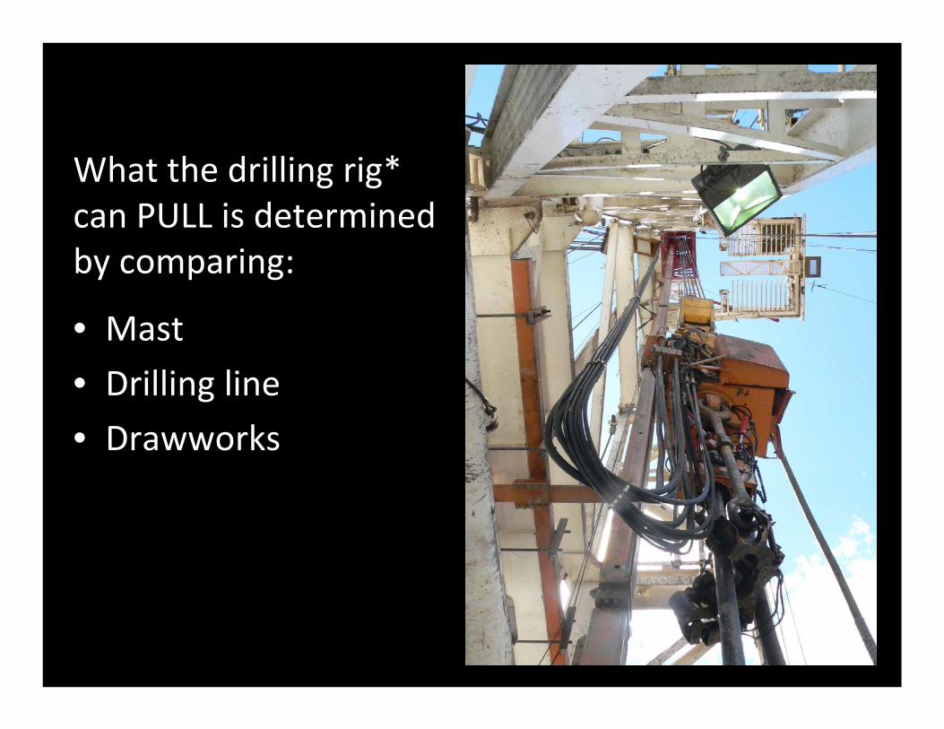
What the drilling rig*can PULL is determinedby comparing:
• Mast
• Drilling line
• Drawworks
8
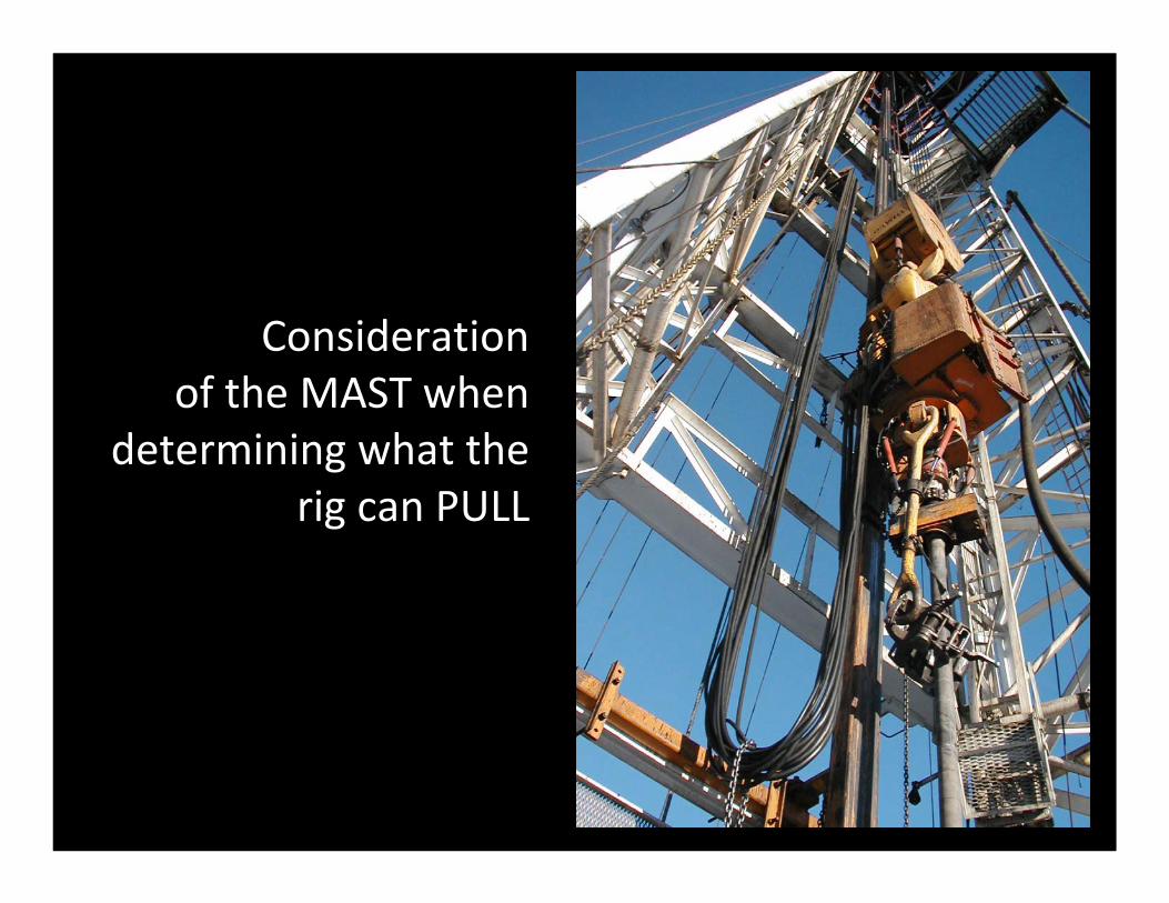
Considerationof the MAST when
determining what the rig can PULL
9

Typical MAST placard as per 3rd Edition of API 4F showing the maximum static hookload capacities
10
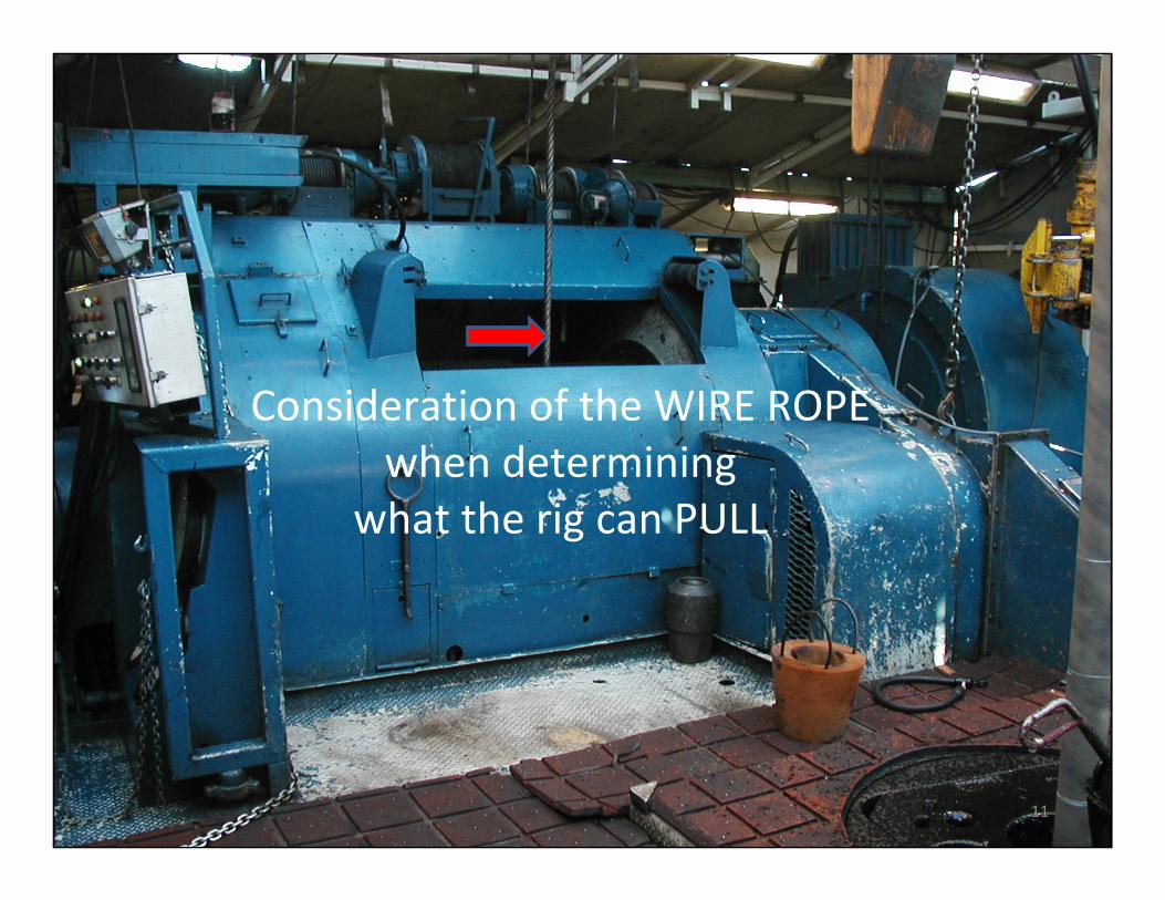
Consideration of the WIRE ROPEwhen determining
what the rig can PULL
11
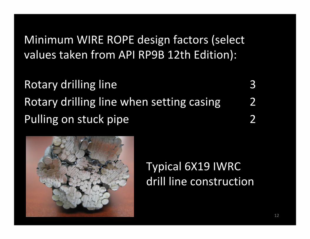
Rotary drilling line 3Rotary drilling line when setting casing 2Pulling on stuck pipe 2
Minimum WIRE ROPE design factors (select values taken from API RP9B 12th Edition):
Typical 6X19 IWRCdrill line construction
12
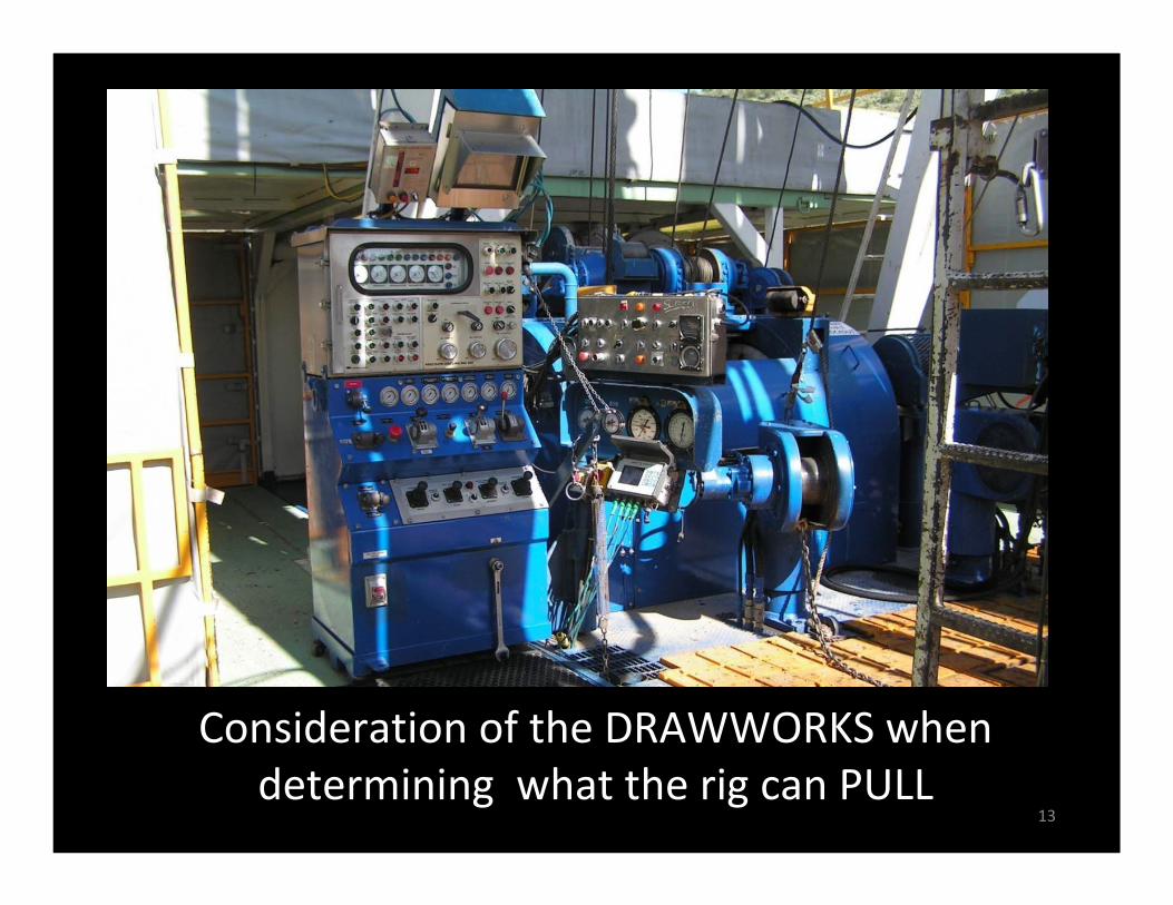
Consideration of the DRAWWORKS when determining what the rig can PULL
13
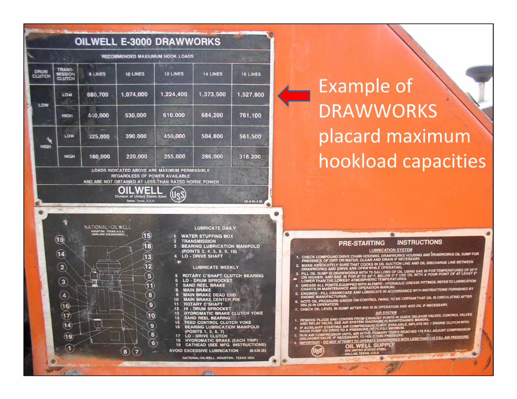
Example of DRAWWORKS placard maximum hookload capacities
14
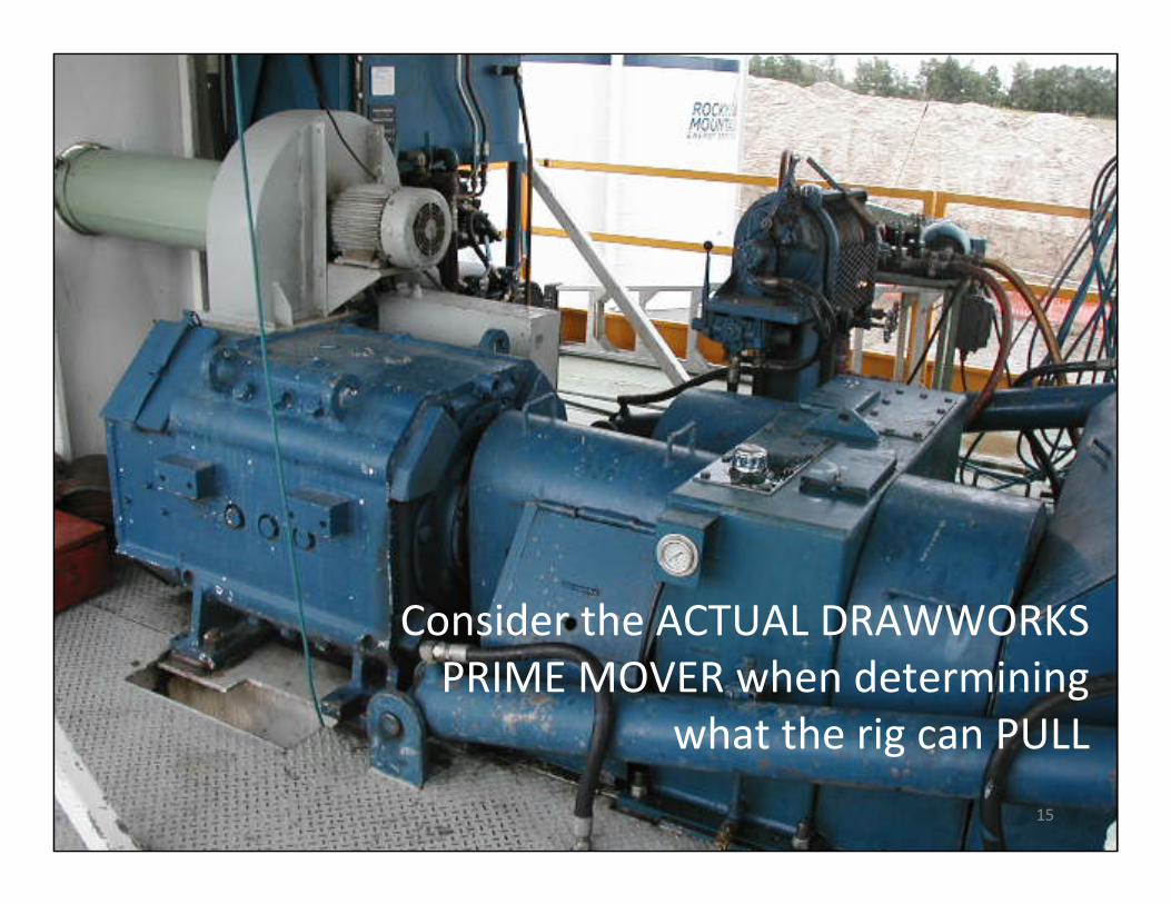
Consider the ACTUAL DRAWWORKS PRIME MOVER when determining
what the rig can PULL
15
16
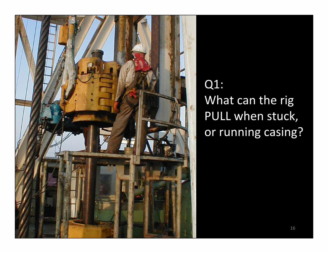
Q1:What can the rig PULL when stuck, or running casing?
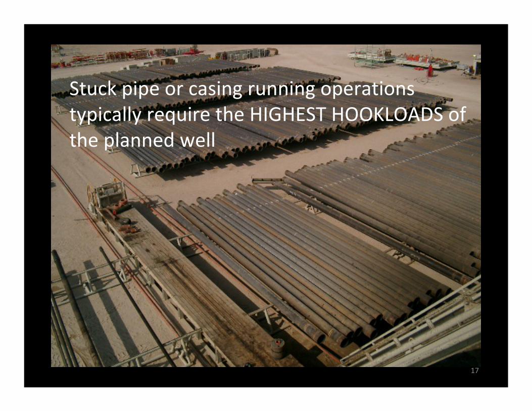
Stuck pipe or casing running operations typically require the HIGHEST HOOKLOADS of the planned well
17
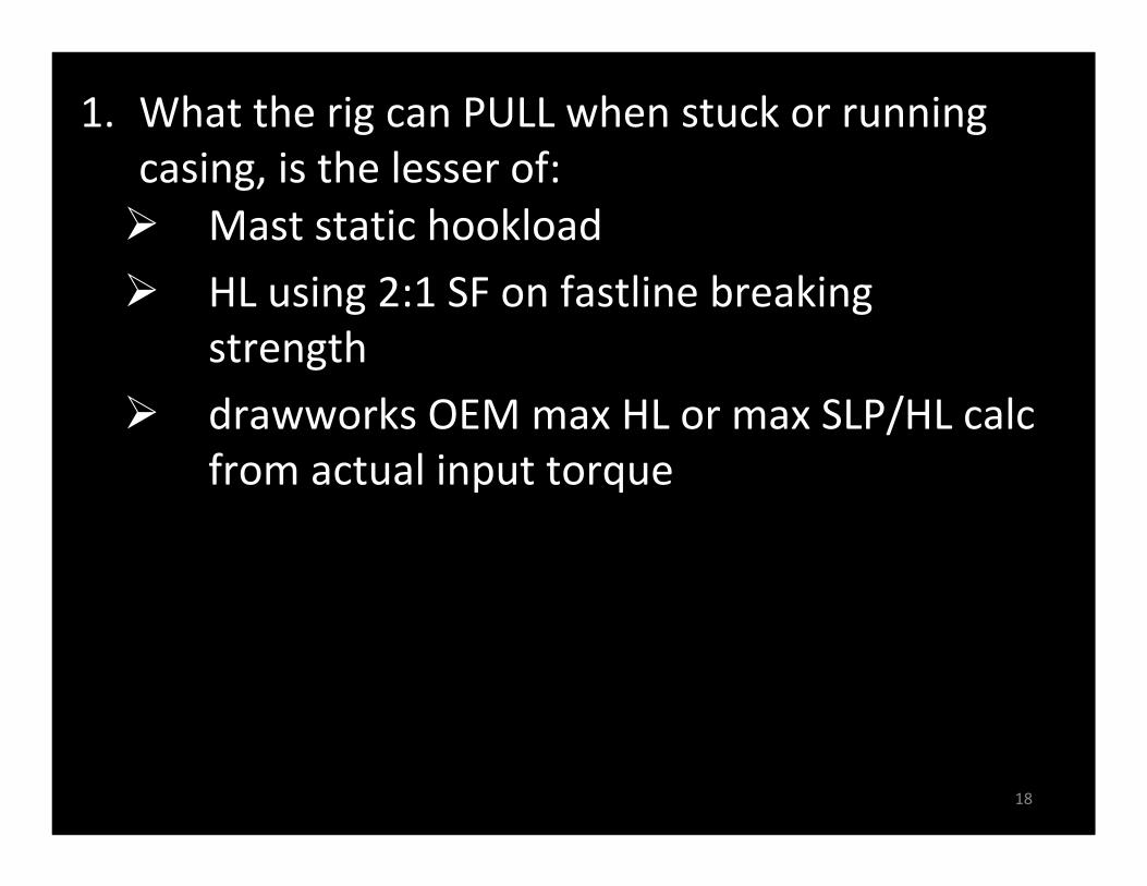
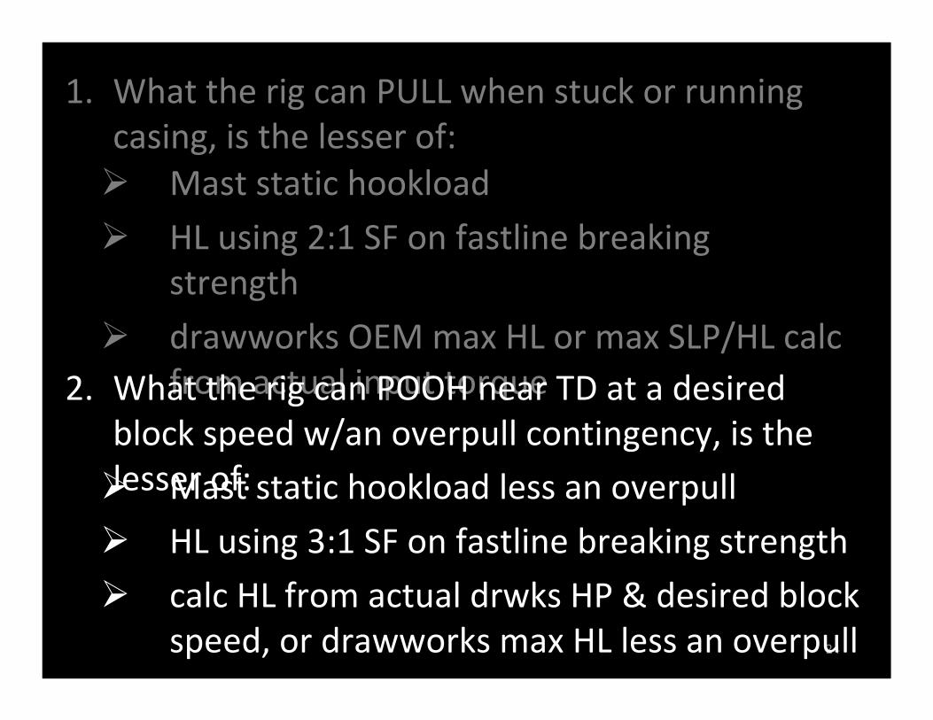
Mast static hookload
HL using 2:1 SF on fastline breaking strength
drawworks OEM max HL or max SLP/HL calc from actual input torque
1. What the rig can PULL when stuck or running casing, is the lesser of:
18
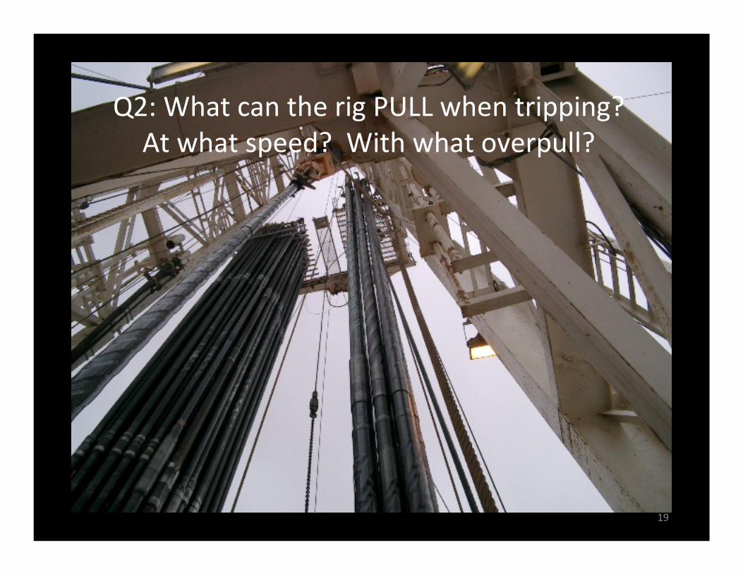
Q2: What can the rig PULL when tripping?At what speed? With what overpull?
19
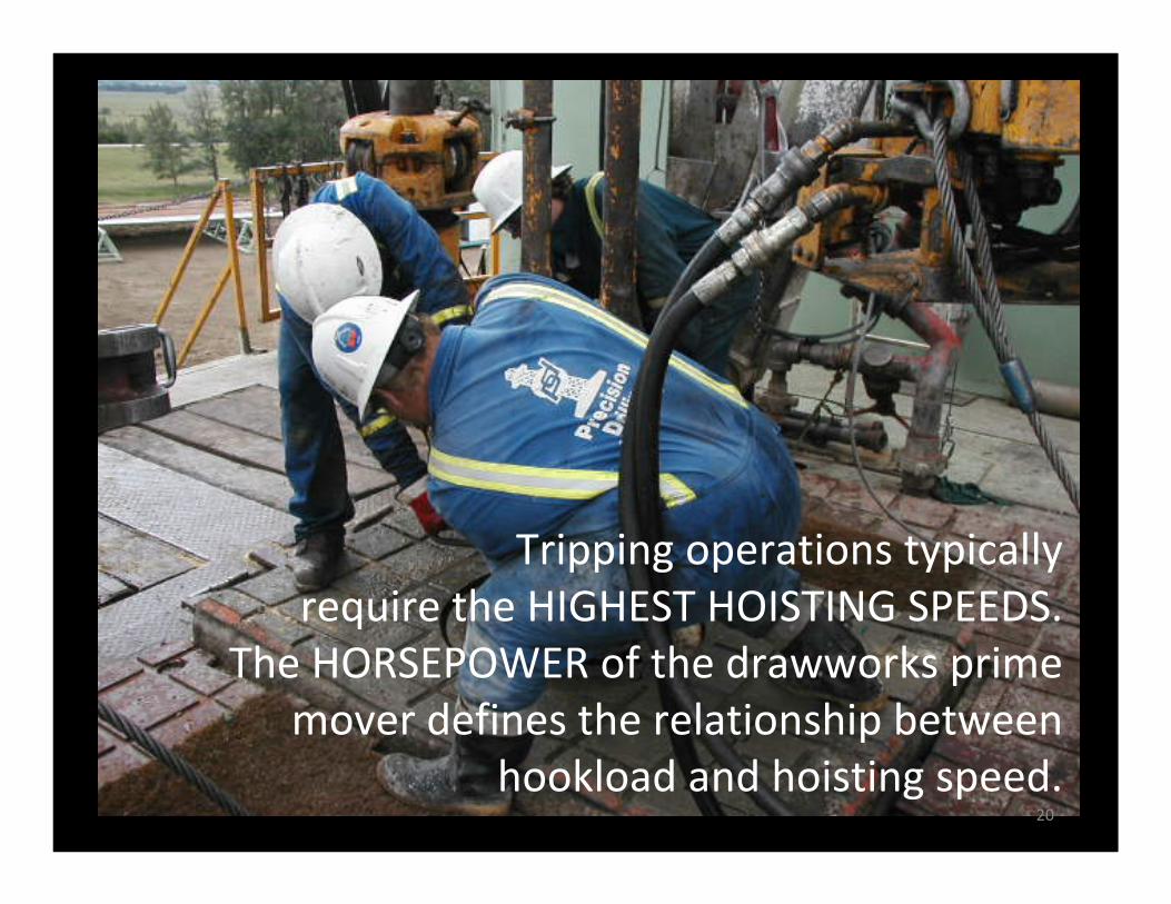
Tripping operations typically require the HIGHEST HOISTING SPEEDS.
The HORSEPOWER of the drawworks prime mover defines the relationship between
hookload and hoisting speed.20
21
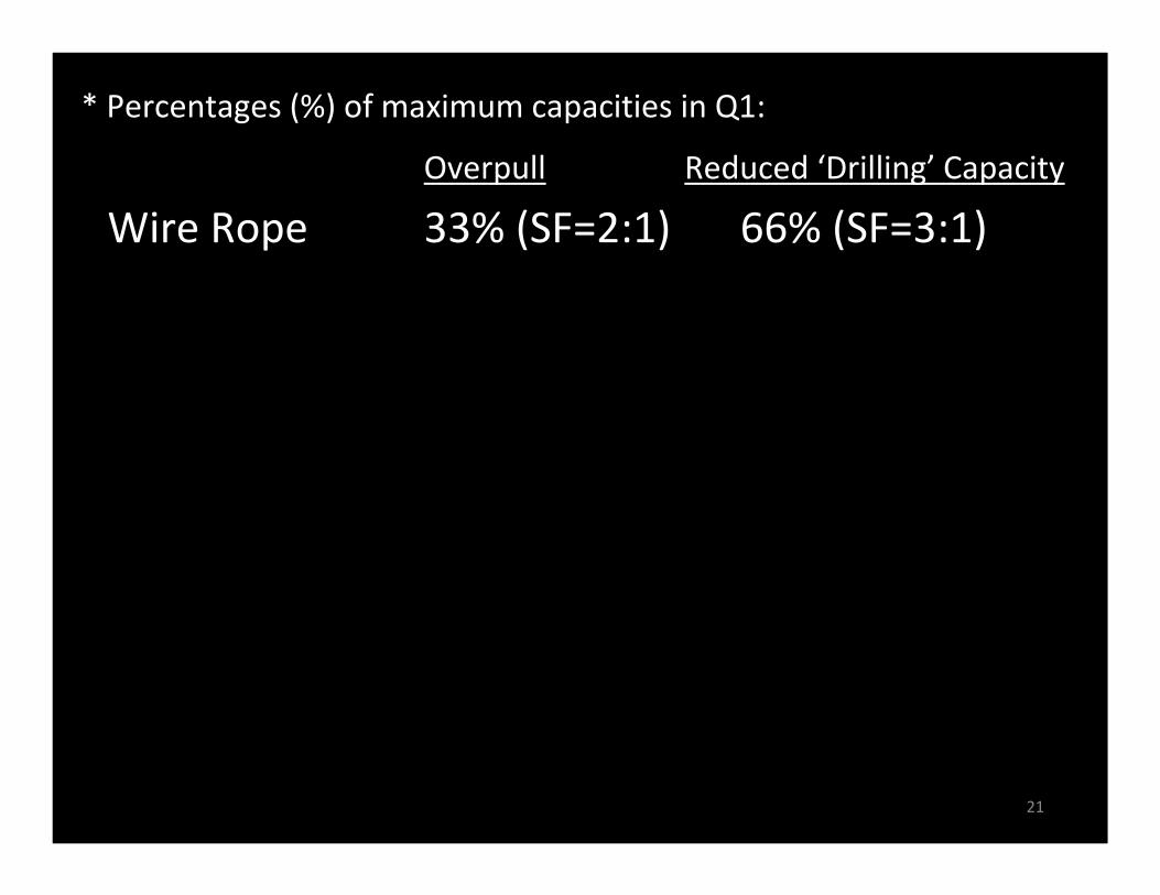
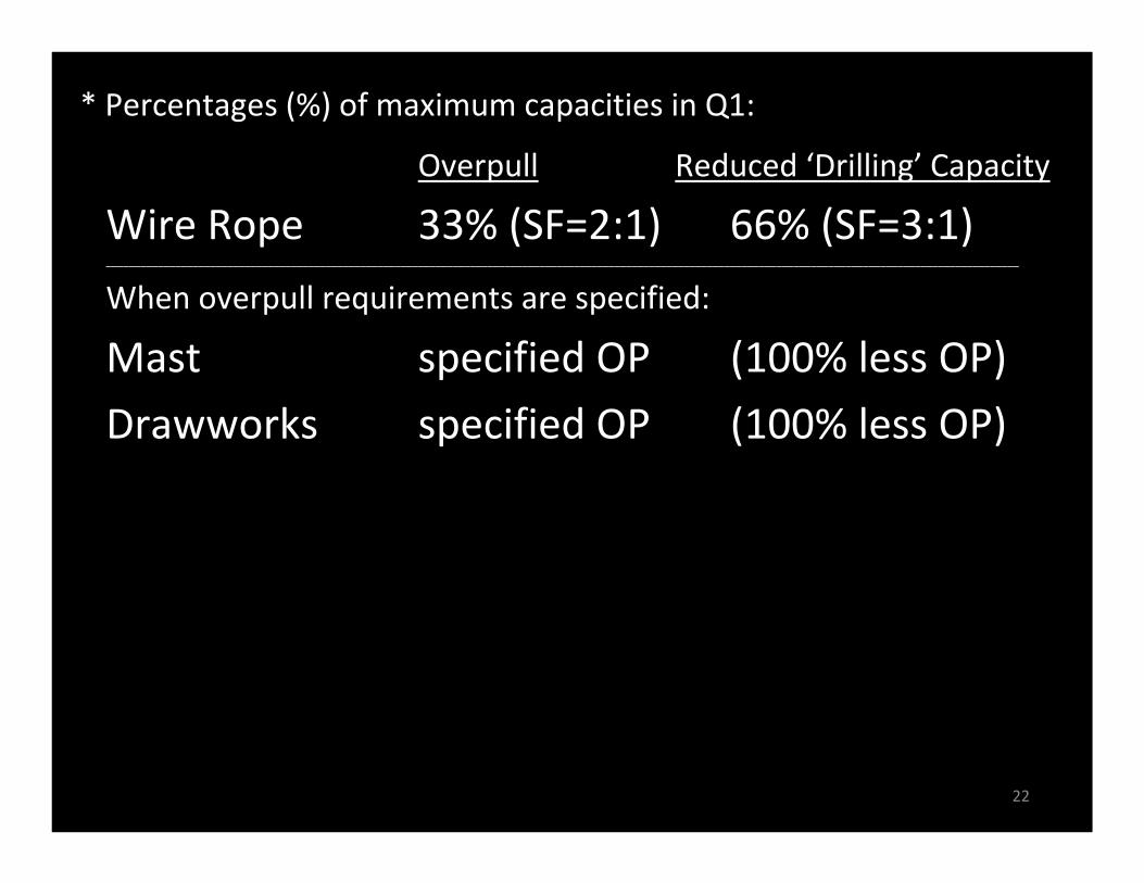
Wire Rope 33% (SF=2:1) 66% (SF=3:1)______________________________________________________________________________________________________________________________________________________________
When overpull requirements are specified:
Mast specified OP (100% less OP)
Drawworks specified OP (100% less OP)______________________________________________________________________________________________________________________________________________________________
Overpull Reduced ‘Drilling’ Capacity
* Percentages (%) of maximum capacities in Q1:
Singles 15% 85%
Doubles 20% 80%
Triples 25% (up to 100kip) 75%
When overpull requirements are NOT specified, the Drilling Contractor can make reductions to the mast & drawworks capacities based on the size of the drilling rig:
22
Wire Rope 33% (SF=2:1) 66% (SF=3:1)______________________________________________________________________________________________________________________________________________________________
When overpull requirements are specified:
Mast specified OP (100% less OP)
Drawworks specified OP (100% less OP)______________________________________________________________________________________________________________________________________________________________
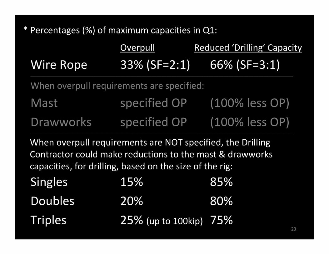
Overpull Reduced ‘Drilling’ Capacity
* Percentages (%) of maximum capacities in Q1:
Singles 15% 85%
Doubles 20% 80%
Triples 25% (up to 100kip) 75%
When overpull requirements are NOT specified, the Drilling Contractor can make reductions to the mast & drawworks capacities based on the size of the drilling rig:
23
Wire Rope 33% (SF=2:1) 66% (SF=3:1)______________________________________________________________________________________________________________________________________________________________
When overpull requirements are specified:
Mast specified OP (100% less OP)
Drawworks specified OP (100% less OP)______________________________________________________________________________________________________________________________________________________________
Overpull Reduced ‘Drilling’ Capacity
* Percentages (%) of maximum capacities in Q1:
Singles 15% 85%
Doubles 20% 80%
Triples 25% (up to 100kip) 75%
When overpull requirements are NOT specified, the Drilling Contractor could make reductions to the mast & drawworks capacities, for drilling, based on the size of the rig:
Mast static hookload
HL using 2:1 SF on fastline breaking strength
drawworks OEM max HL or max SLP/HL calc from actual input torque
1. What the rig can PULL when stuck or running casing, is the lesser of:
24
Mast static hookload less an overpull
HL using 3:1 SF on fastline breaking strength
calc HL from actual drwks HP & desired block speed, or drawworks max HL less an overpull
2. What the rig can POOH near TD at a desired block speed w/an overpull contingency, is the lesser of:
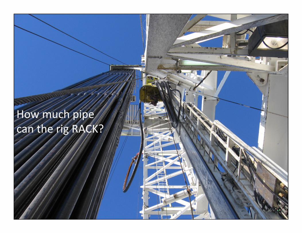
How much pipecan the rig RACK?
25
‘RACKING CAPACITY – number of stands that can be stood on the floor based on the geometryof the monkeyboard and racking floor
‘SETBACK CAPACITY – maximum uniform weightof tubulars that can be supported by the racking floor
Clarification of term definitions – as they relate to this presentation:
26
What can the rig PULL?
1. when stuck, or when running casing?
2. when POOH near TD?
How much pipe can the rig RACK?
3. based on geometry?
4. based on weight?
27
Four (4) ALTERNATE metrics:
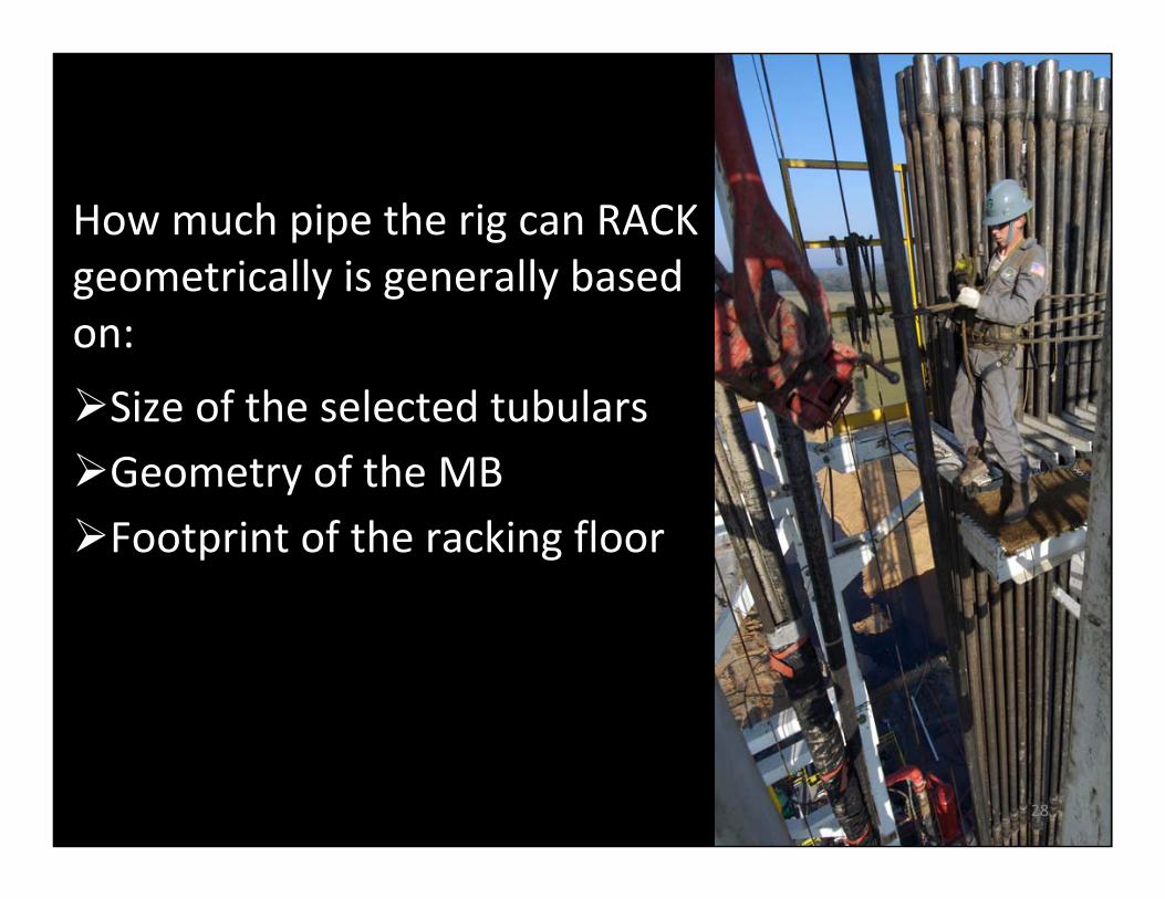
How much pipe the rig can RACK geometrically is generally based on:
Size of the selected tubularsGeometry of the MBFootprint of the racking floor
28
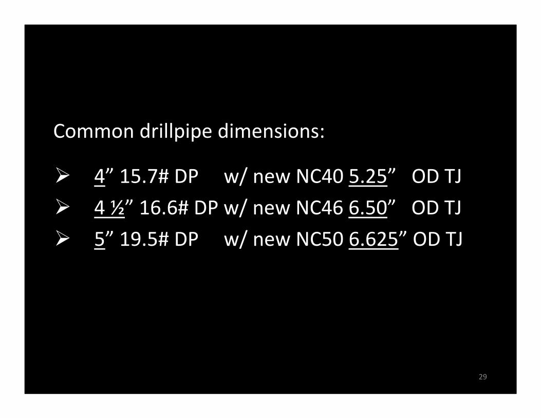
4” 15.7# DP w/ new NC40 5.25” OD TJ
4 ½” 16.6# DP w/ new NC46 6.50” OD TJ
5” 19.5# DP w/ new NC50 6.625” OD TJ
Common drillpipe dimensions:
29
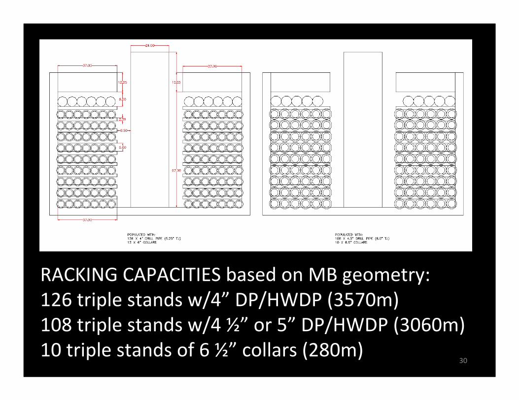
RACKING CAPACITIES based on MB geometry:126 triple stands w/4” DP/HWDP (3570m)108 triple stands w/4 ½” or 5” DP/HWDP (3060m)10 triple stands of 6 ½” collars (280m)
30
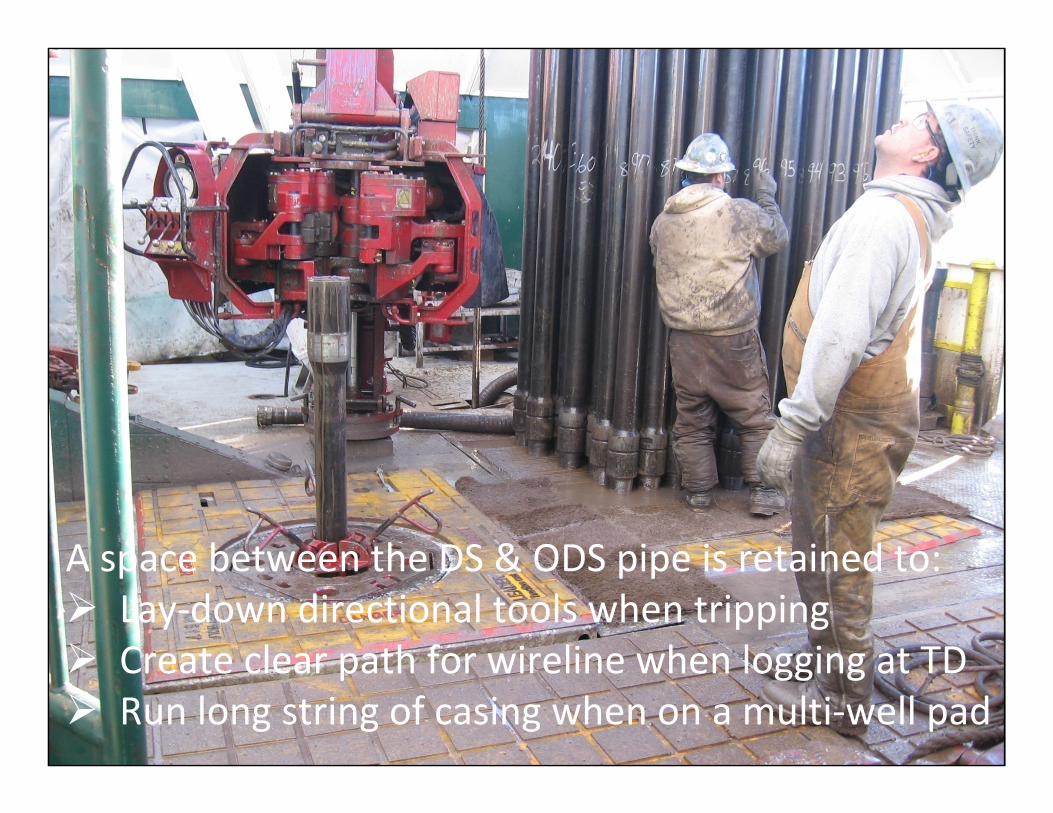
A space between the DS & ODS pipe is retained to:Lay‐down directional tools when trippingCreate clear path for wireline when logging at TDRun long string of casing when on a multi‐well pad
m31
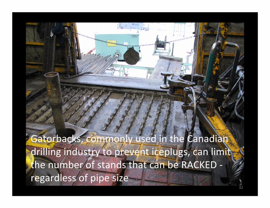
Gatorbacks, commonly used in the Canadian drilling industry to prevent iceplugs, can limit the number of stands that can be RACKED ‐regardless of pipe size
32
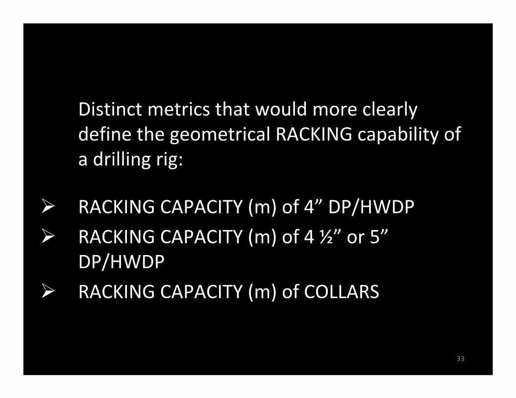
Distinct metrics that would more clearly define the geometrical RACKING capability of a drilling rig:
RACKING CAPACITY (m) of 4” DP/HWDP
RACKING CAPACITY (m) of 4 ½” or 5”DP/HWDP
RACKING CAPACITY (m) of COLLARS
33
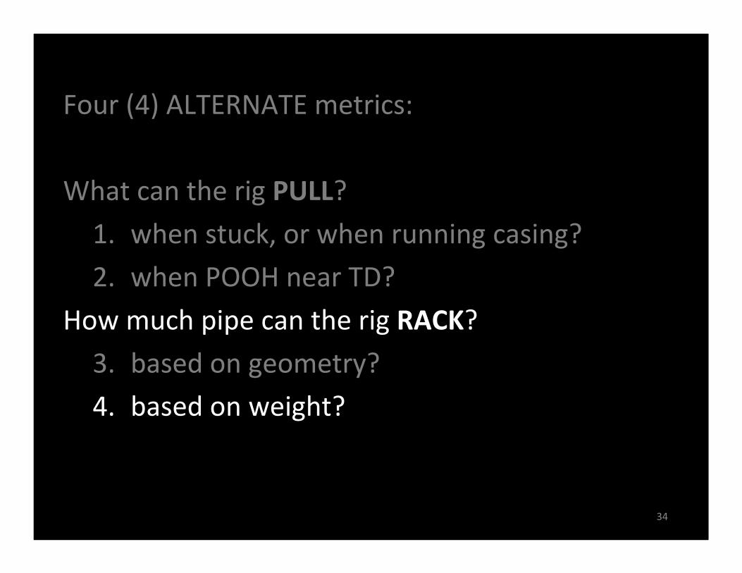
Four (4) ALTERNATE metrics:
What can the rig PULL?
1. when stuck, or when running casing?
2. when POOH near TD?
How much pipe can the rig RACK?
3. based on geometry?
4. based on weight?
34
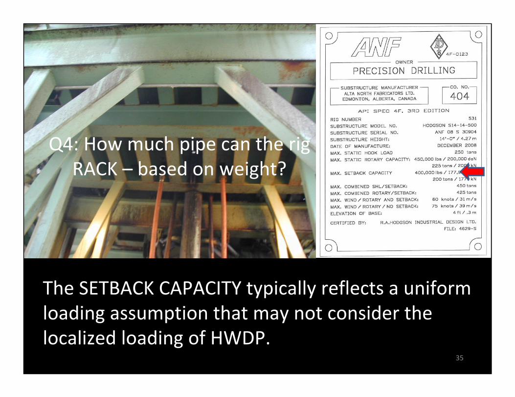
The SETBACK CAPACITY typically reflects a uniform loading assumption that may not consider the localized loading of HWDP.
35
Q4: How much pipe can the rig RACK – based on weight?
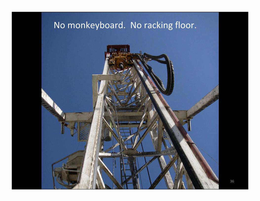
No monkeyboard. No racking floor.
36
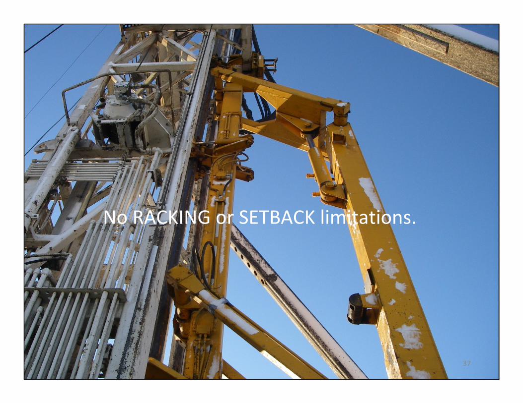
No RACKING or SETBACK limitations.
37
This presentation encourages the Operator and Drilling Contractor to collaboratively determine the loads that are specific to the planned well(s); and compare these estimated loads to a more transparent summary of DRILLING RIG CAPABILITIES – rather than rely on an ambiguous rig depth rating to evaluate the suitability of a particular rig for a particular well program.
Doing so will refine the rig selection process; and may ultimately reduce the COST to drill the planned well(s).
38
Thank‐you for your interest in this presentation.
Are there any questions?
Evaluation of Drilling Rig Performance Characteristics
Quinton T. Foulston, P.Eng. Ph. 403‐716‐4642
39