Evaluation of coordinate measurement uncertainty by ... · KEYWORDS: measurement uncertainty,...
4
MECHANIK NR 11/2018 How to cite this article: Author: Wojciech Płowucha Title of article: „Szacowanie niepewności pomiarów współrzędnościowych metodą analizy wrażliwości – podstawy teoretyczne” (“Evaluation of coordinate measurement uncertainty by sensitivity analysis – theoretical background”) Mechanik, Vol. 91, No. 11 (2018): pages 953–956 DOI: https://doi.org/10.17814/mechanik.2018.11.168 Evaluation of coordinate measurement uncertainty by sensitivity analysis – theoretical background Szacowanie niepewności pomiarów współrzędnościowych metodą analizy wrażliwości – podstawy teoretyczne WOJCIECH PŁOWUCHA * Theoretical background of new method for uncertainty evaluation was presented on the examples of measurement of circle and arc radius. The method uses the formula for CMM maximum permissible error of length measurement and the reverification test results as the input data. KEYWORDS: measurement uncertainty, sensitivity analysis, coordinate measurement The estimation of the uncertainty of coordinate measurements is one of the important problems in the face of the widespread use of coordinate measuring machines (CMM). The previous approach to this issue, however, makes them inaccessible, and even not understandable to an ordinary user. ATH is working on ordering and disseminating this issue [1]. The ISO/TS 15530-1 [2] technical specification distinguishes three methods for estimating measurement uncertainty. The method with the use of the reference object has been given the ISO 15530-3 standard [3] and is described in detail in [4]. The method with the use of simulation is the subject of the technical specification ISO/TS 15530-4 [5]. Its use is limited because it requires the use of special software. The third – the method of sensitivity analysis – according to ingrained conviction is only suitable for estimating uncertainty in the case of simple tasks. This statement refers to the publication [6], in which, as an example of application, a publication [7] on the estimation of uncertainty in the measurement of small hole diameters is pointed out. It is true that there exists a document VDI/VDE 2617-11 [8], which formally contains information for estimating the uncertainty of the coordinate measurements using the sensitivity analysis method, but the described procedure is complex, and the two examples in it refer only to the diameter and distance of the axis from plane. Significant barriers to the use of the sensitivity analysis method include the large number of sampling points and the complexity of measurement models that require knowledge of geometric CMM errors. The first obstacle was overcome when Jakubiec et al. [9] defined the measurement model based on the minimum mathematical number of points and indicated the possibility of treating the coordinate measurement as indirect, where the direct measurements are differences in the coordinates of pairs of points, and the measurement of coordinate differences can be estimated on the basis statistical information on geometrical errors and CMM head error. The developed method is universal, but its significant disadvantage is the considerable labor-intensity at the stage of identifying CMM errors [10, 11]. The author of this publication noted that if the uncertainty of measuring coordinate differences is expressed using the formula for the maximum permissible error of length measurement (EL, MPE), then a significant simplification of the required analyzes is obtained, at the expense of possible slight over-estimation of measurement uncertainty [12]. On this basis, the method was developed in accordance with the modern approach to estimating the uncertainty of measurements, and at the same time it is a simple methodology, taking into account the existing coordinate techniques and thus possible for direct application. Essence of the new method of sensitivity analysis As a preliminary to the description of a new method for estimating the uncertainty of a coordinate measurement, a known example of estimating the uncertainty of the measurement of the mean radius of a flat arc of an object will be given. The measurement is made using a measuring microscope, and the measured quantities are directly arrow s and chord c (fig. 1). Fig. 1. Principle of radius measurement with a microscope The radius of the arc R is calculated according to the formula: = 2 8 + 2 (1) * Dr inż. Wojciech Płowucha ([email protected]) – Akademia Techniczno-Humanistyczna w Bielsku-Białej, Laboratorium Metrologii
Transcript of Evaluation of coordinate measurement uncertainty by ... · KEYWORDS: measurement uncertainty,...
MECHANIK NR 11/2018
How to cite this article:
Author: Wojciech Płowucha
Title of article: „Szacowanie niepewności pomiarów współrzędnościowych metodą analizy wrażliwości – podstawy teoretyczne” (“Evaluation of coordinate measurement uncertainty by sensitivity analysis – theoretical background”)
Mechanik, Vol. 91, No. 11 (2018): pages 953–956
DOI: https://doi.org/10.17814/mechanik.2018.11.168
Evaluation of coordinate measurement uncertainty
by sensitivity analysis – theoretical background
Szacowanie niepewności pomiarów współrzędnościowych metodą analizy wrażliwości – podstawy teoretyczne
WOJCIECH PŁOWUCHA *
Theoretical background of new method for uncertainty evaluation was presented on the examples of measurement of circle and arc radius. The method uses the formula for CMM maximum permissible error of length measurement and the reverification test results as the input data. KEYWORDS: measurement uncertainty, sensitivity analysis, coordinate measurement
The estimation of the uncertainty of coordinate measurements is one of the important problems in the face of the widespread use of coordinate measuring machines (CMM). The previous approach to this issue, however, makes them inaccessible, and even not understandable to an ordinary user. ATH is working on ordering and disseminating this issue [1].
The ISO/TS 15530-1 [2] technical specification distinguishes three methods for estimating measurement uncertainty. The method with the use of the reference object has been given the ISO 15530-3 standard [3] and is described in detail in [4]. The method with the use of simulation is the subject of the technical specification ISO/TS 15530-4 [5]. Its use is limited because it requires the use of special software. The third – the method of sensitivity analysis – according to ingrained conviction is only suitable for estimating uncertainty in the case of simple tasks. This statement refers to the publication [6], in which, as an example of application, a publication [7] on the estimation of uncertainty in the measurement of small hole diameters is pointed out. It is true that there exists a document VDI/VDE 2617-11 [8], which formally contains information for estimating the uncertainty of the coordinate measurements using the sensitivity analysis method, but the described procedure is complex, and the two examples in it refer only to the diameter and distance of the axis from plane.
Significant barriers to the use of the sensitivity analysis method include the large number of sampling points and the complexity of measurement models that require knowledge of geometric CMM errors. The first obstacle was overcome when Jakubiec et al. [9] defined the measurement model based on the minimum mathematical number of points and indicated the possibility of treating the coordinate measurement as indirect, where the direct measurements are differences in the coordinates of pairs of points, and the
measurement of coordinate differences can be estimated on the basis statistical information on geometrical errors and CMM head error. The developed method is universal, but its significant disadvantage is the considerable labor-intensity at the stage of identifying CMM errors [10, 11].
The author of this publication noted that if the uncertainty of measuring coordinate differences is expressed using the formula for the maximum permissible error of length measurement (EL, MPE), then a significant simplification of the required analyzes is obtained, at the expense of possible slight over-estimation of measurement uncertainty [12]. On this basis, the method was developed in accordance with the modern approach to estimating the uncertainty of measurements, and at the same time it is a simple methodology, taking into account the existing coordinate techniques and thus possible for direct application.
Essence of the new method of sensitivity analysis
As a preliminary to the description of a new method for
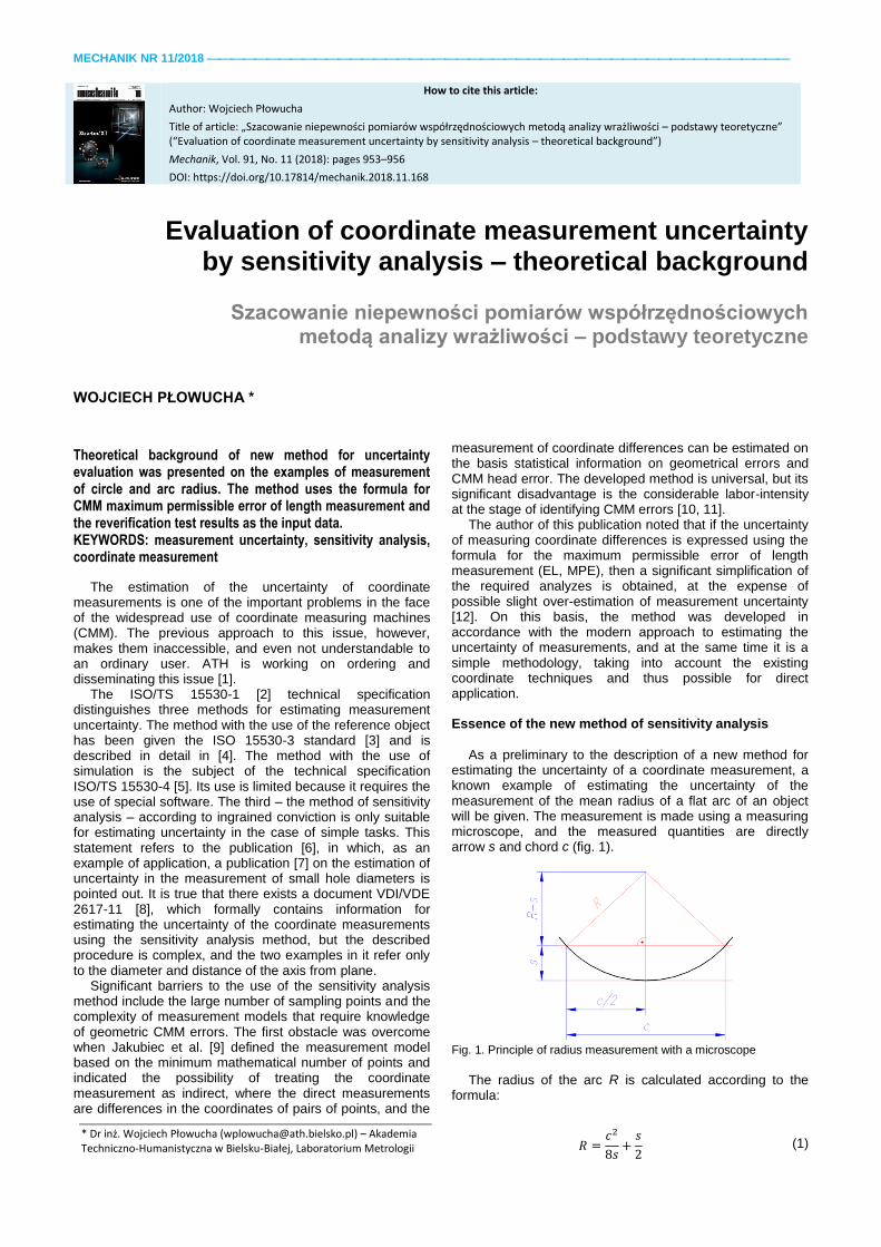
estimating the uncertainty of a coordinate measurement, a known example of estimating the uncertainty of the measurement of the mean radius of a flat arc of an object will be given. The measurement is made using a measuring microscope, and the measured quantities are directly arrow s and chord c (fig. 1).
Fig. 1. Principle of radius measurement with a microscope
The radius of the arc R is calculated according to the
formula:
𝑅 =𝑐2
8𝑠+𝑠
2 (1)
* Dr inż. Wojciech Płowucha ([email protected]) – Akademia Techniczno-Humanistyczna w Bielsku-Białej, Laboratorium Metrologii
MECHANIK NR 11/2018
and the complex standard uncertainty of measurement (assuming no correlation) – from the formula:
𝑢𝑅 = √(𝜕𝑅
𝜕𝑐∙ 𝑢𝑐)
2
+ (𝜕𝑅
𝜕𝑠∙ 𝑢𝑠)
2
(2)
wherein:
𝜕𝑅
𝜕𝑐=
𝑐
4𝑠 (3)
𝜕𝑅
𝜕𝑠=−𝑐2
8𝑠2+1
2 (4)
According to the modern approach to the estimation of
measurement uncertainty, both the standard uncertainties us and uc can be estimated using the B method, based on the pattern of the limit error of the length measurement, which for microscopes and CMM assumes the general form of type EL, MPE = A + BL.
The ISO 14253-2 [13, p. 8.4.5] standard as one of the possibilities of estimating uncertainty takes into account the adoption of EL, MPE as the highest possible value of this error (a = EL, MPE) and selection of the appropriate probability distribution , on the basis of which you can convert the value of a to standard uncertainty. When using the uniform
distribution 𝑢 = 𝑎/√3. It is quite common to justify the use of
a normal distribution and then you can accept 𝑢 = 𝑎/2 or
even 𝑢 = 𝑎/3 [14]. In this article, the last of these
possibilities was adopted; then:
𝑢𝑐 = (𝐴 + 𝐵𝑐)/3 (5)
𝑢𝑠 = (𝐴 + 𝐵𝑠)/3 (6)
There are three examples of the development of
measurement results for the same subject, differing in the adopted strategy, namely the value of the arrow s. The calculation assumes that the maximum permissible error of measuring the length of EL, MPE = 2 + 0.004L.
The development of measurement results of the same subject (R = 50 mm) in the form of uncertainty budgets for various values of arrow s is shown in tabs. I–III.
TABLE I. Uncertainty budget for the measurement of the radius of the arch by a microscope; arch arrow s = 8 mm
mm 𝜕𝑅/𝜕 ui, μm 𝜕𝑅/𝜕 ∙ 𝑢𝑖, μm
s 8.000 -5.25 0.68 -3.56
c 54.259 1.7 0.75 1.25
u = 3.77
TABLE II. Uncertainty budget for the measurement of the radius of the arch by a microscope; arch arrow s = 25 mm
mm 𝜕𝑅/𝜕 ui, μm 𝜕𝑅/𝜕 ∙ 𝑢𝑖, μm
s 25.000 -1.00 0.70 -0.70
c 86.603 0.87 0.78 0.68
u = 0.97
TABLE III. Uncertainty budget for the measurement of the radius of the arch by a microscope; arch arrow s = 50 mm
mm 𝜕𝑅/𝜕 ui, μm 𝜕𝑅/𝜕 ∙ 𝑢𝑖, μm
s 50.000 0 0.73 0
c 100.001 0.5 0.8 0.40
u = 0.40
The examples indicate that the measurement uncertainty
of the radius of the arc depends significantly on the measurement strategy. Although the measurements are made with the same device, the uncertainty decreases with
the increase of the arc arrow value adopted for measurement. In the last example, we measure the diameter: the derivative after s is equal to zero, which means that the measurement uncertainty of the arrow does not affect the uncertainty of the radius measurement.
Sensitivity analysis in relation to the measurement of the co-ordinate radius of a circle arc
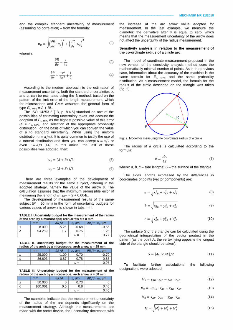
The model of coordinate measurement proposed in the
new version of the sensitivity analysis method uses the mathematically minimal number of points. As in the previous case, information about the accuracy of the machine is the same formula for EL, MPE and the same probability distribution. As a measurement model, the formula for the radius of the circle described on the triangle was taken (fig. 2).
Fig. 2. Model for measuring the coordinate radius of a circle
The radius of a circle is calculated according to the
formula:
𝑅 =𝑎𝑏𝑐
4𝑆 (7)
where: a, b, c – side lengths; S – the surface of the triangle. The sides lengths expressed by the differences in
coordinates of points (vector components) are:
𝑎 = √𝑥𝐶𝐵2 + 𝑦𝐶𝐵
2 + 𝑧𝐶𝐵2 (8)
𝑏 = √𝑥𝐴𝐶2 + 𝑦𝐴𝐶
2 + 𝑧𝐴𝐶2 (9)
𝑐 = √𝑥𝐴𝐵2 + 𝑦𝐴𝐵
2 + 𝑧𝐴𝐵2 (10)
The surface S of the triangle can be calculated using the
geometrical interpretation of the vector product in the pattern (as the point A, the vertex lying opposite the longest side of the triangle should be taken):
𝑆 = |𝐴𝐵 × 𝐴𝐶|/2 (11)
To facilitate further calculations, the following
designations were adopted:
𝑀1 = 𝑦𝐴𝐵 ∙ 𝑧𝐴𝐶 − 𝑧𝐴𝐵 ∙ 𝑦𝐴𝐶 (12)
𝑀2 = −𝑥𝐴𝐵 ∙ 𝑧𝐴𝐶 + 𝑧𝐴𝐵 ∙ 𝑥𝐴𝐶 (13)
𝑀3 = 𝑥𝐴𝐵 ∙ 𝑦𝐴𝐶 − 𝑦𝐴𝐵 ∙ 𝑥𝐴𝐶 (14)
𝑀 = √𝑀12 +𝑀2
2 +𝑀32 (15)
MECHANIK NR 11/2018
Finally, the radius R can be written as:
𝑅 =𝑎𝑏𝑐
2𝑀 (16)
Radius R is a function of nine components of the AB
vectors (xAB, yAB, zAB), AC (xAC, yAC, zAC) and CB (xCB, yCB, zCB), or else: nine coordinate differences of points A, B and C.
The measurement uncertainty of the radius is calculated from the formula:
𝑢𝑅 = √∑(𝜕𝑅
𝜕𝑥𝑖𝑢𝑥𝑖)
29
𝑖=1
(17)
where the differences in x, y and z coordinates are generally designated as xi, the standard uncertainties of their measurement are generally designated as uxi and calculated (similar to the previous one) according to the formula:
𝑢𝑥𝑖 = 𝐸𝐿,𝑀𝑃𝐸/3 = (2 + 0,004𝑥𝑖)/3 (18)
The necessary partial derivatives needed for the budget
are as follows:
𝜕𝑅
𝜕𝑥𝐴𝐵=𝑎𝑏𝑥𝐴𝐵2𝑐𝑀
−𝑎𝑏𝑐(−𝑀2𝑧𝐴𝐶 +𝑀3𝑦𝐴𝐶)
2𝑀3 (19)
𝜕𝑅
𝜕𝑦𝐴𝐵=𝑎𝑏𝑦𝐴𝐵2𝑐𝑀
−𝑎𝑏𝑐(𝑀1𝑧𝐴𝐶 −𝑀3𝑥𝐴𝐶)
2𝑀3 (20)
𝜕𝑅
𝜕𝑧𝐴𝐵=𝑎𝑏𝑧𝐴𝐵2𝑐𝑀
−𝑎𝑏𝑐(−𝑀1𝑧𝐴𝐶 +𝑀2𝑦𝐴𝐶)
2𝑀3 (21)
𝜕𝑅
𝜕𝑥𝐴𝐶=𝑎𝑐𝑥𝐴𝐶2𝑏𝑀
−𝑎𝑏𝑐(𝑀2𝑧𝐴𝐵 −𝑀3𝑦𝐴𝐵)
2𝑀3 (22)
𝜕𝑅
𝜕𝑦𝐴𝐶=𝑎𝑐𝑦𝐴𝐶2𝑏𝑀
−𝑎𝑏𝑐(−𝑀1𝑧𝐴𝐵 +𝑀3𝑥𝐴𝐵)
2𝑀3 (23)
𝜕𝑅
𝜕𝑧𝐴𝐶=𝑎𝑐𝑧𝐴𝐶2𝑏𝑀
−𝑎𝑏𝑐(𝑀1𝑦𝐴𝐵 −𝑀2𝑥𝐴𝐵)
2𝑀3 (24)
𝜕𝑅
𝜕𝑥𝐶𝐵=𝑏𝑐𝑥𝐶𝐵2𝑎𝑀
(25)
𝜕𝑅
𝜕𝑦𝐶𝐵=𝑏𝑐𝑦𝐶𝐵2𝑎𝑀
(26)
𝜕𝑅
𝜕𝑧𝐶𝐵=𝑏𝑐𝑧𝐶𝐵2𝑎𝑀
(27)
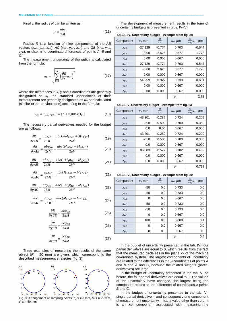
Three examples of measuring the results of the same
object (R = 50 mm) are given, which correspond to the described measurement strategies (fig. 3). a) b) c)
Fig. 3. Arrangement of sampling points: a) s = 8 mm, b) s = 25 mm, c) s = 50 mm
The development of measurement results in the form of uncertainty budgets is presented in tabs. IV–VI.
TABLE IV. Uncertainty budget – example from fig. 3a
Component xi, mm 𝜕𝑙
𝜕𝑥𝑖 uxi, m
𝜕𝑙
𝜕𝑥𝑖𝑢𝑥𝑖, m
xAB -27.129 -0.774 0.703 -0.544
yAB -8.00 2.625 0.677 1.778
zAB 0.00 0.000 0.667 0.000
xAC 27.129 0.774 0.703 0.544
yAC -8.00 2.625 0.677 1.778
zAC 0.00 0.000 0.667 0.000
xBC 54.259 0.922 0.739 0.681
yBC 0.00 0.000 0.667 0.000
zBC 0.00 0.000 0.667 0.000
u = 2.72
TABLE V. Uncertainty budget – example from fig. 3b
Component xi, mm 𝜕𝑙
𝜕𝑥𝑖 uxi, m
𝜕𝑙
𝜕𝑥𝑖𝑢𝑥𝑖, m
xAB -43.301 -0.289 0.724 -0.209
yAB -25.0 0.500 0.700 0.350
zAB 0.0 0.00 0.667 0.000
xAC 43.301 0.289 0.724 0.209
yAC -25.0 0.500 0.700 0.350
zAC 0.0 0.000 0.667 0.000
xBC 86.603 0.577 0.782 0.452
yBC 0.0 0.000 0.667 0.000
zBC 0.0 0.000 0.667 0.000
u = 0.732
TABLE VI. Uncertainty budget – example from fig. 3c
Component xi, mm 𝜕𝑙
𝜕𝑥𝑖 uxi, m
𝜕𝑙
𝜕𝑥𝑖𝑢𝑥𝑖, m
xAB -50 0.0 0.733 0.0
yAB -50 0.0 0.733 0.0
zAB 0 0.0 0.667 0.0
xAC 50 0.0 0.733 0.0
yAC -50 0.0 0.733 0.0
zAC 0 0.0 0.667 0.0
xBC 100 0.5 0.800 0.4
yBC 0 0.0 0.667 0.0
zBC 0 0.0 0.667 0.0
u = 0.4
In the budget of uncertainty presented in the tab. IV, four
partial derivatives are equal to 0, which results from the fact that the measured circle lies in the plane xy of the machine co-ordinate system. The largest components of uncertainty are related to the differences in the y-coordinates of points A and B and A and C, because the related weights (partial derivatives) are large.
In the budget of uncertainty presented in the tab. V, as before, the four partial derivatives are equal to 0. The values of the uncertainty have changed, the largest being the component related to the difference of coordinates x points B and C.
In the budget of uncertainty presented in the tab. VI, single partial derivative – and consequently one component of measurement uncertainty – has a value other than zero. It is an xBC component associated with measuring the
MECHANIK NR 11/2018
difference of x coordinates lying on the diameter of B and C points. The obtained uncertainty of measurement is less than in the previous example. Sampling strategy refers to a direct two-point diameter measurement. Point A is involved in the measurement only in that it indicates where the diameter of the circle is to be measured. A similar effect can be obtained when points B and C lie close to each other facing point A.
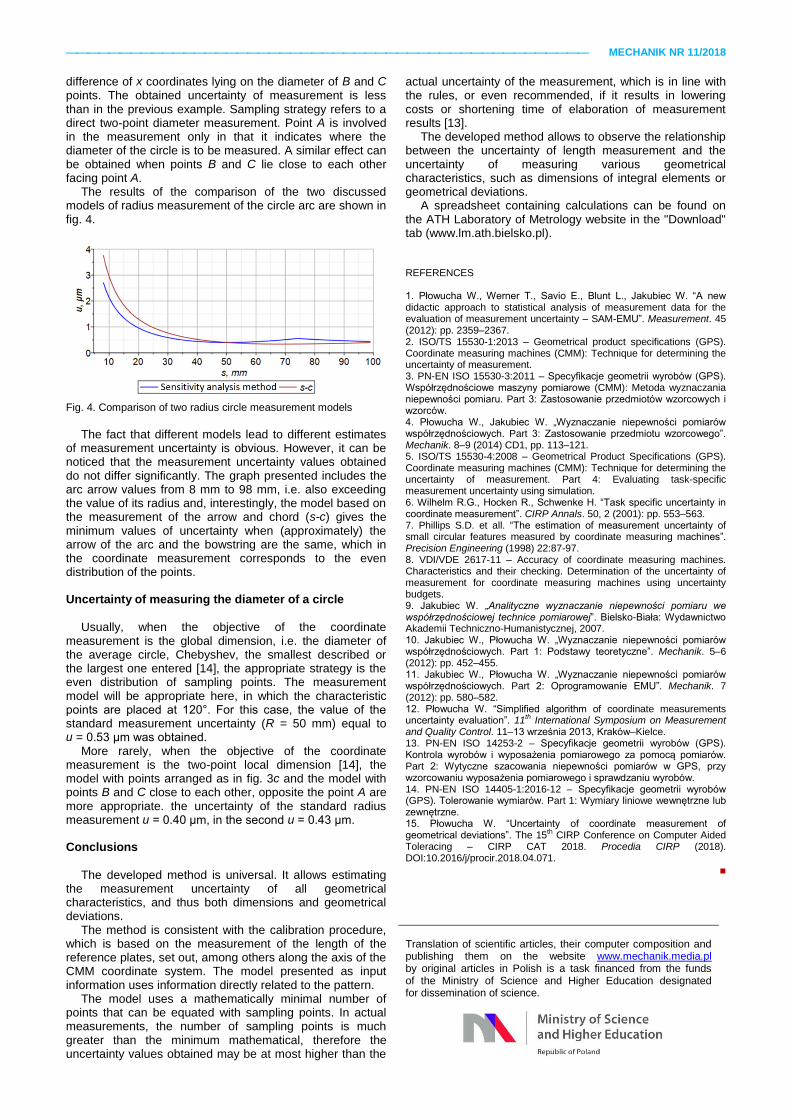
The results of the comparison of the two discussed models of radius measurement of the circle arc are shown in fig. 4.
Fig. 4. Comparison of two radius circle measurement models
The fact that different models lead to different estimates
of measurement uncertainty is obvious. However, it can be noticed that the measurement uncertainty values obtained do not differ significantly. The graph presented includes the arc arrow values from 8 mm to 98 mm, i.e. also exceeding the value of its radius and, interestingly, the model based on the measurement of the arrow and chord (s-c) gives the minimum values of uncertainty when (approximately) the arrow of the arc and the bowstring are the same, which in the coordinate measurement corresponds to the even distribution of the points.
Uncertainty of measuring the diameter of a circle
Usually, when the objective of the coordinate
measurement is the global dimension, i.e. the diameter of the average circle, Chebyshev, the smallest described or the largest one entered [14], the appropriate strategy is the even distribution of sampling points. The measurement model will be appropriate here, in which the characteristic points are placed at 120°. For this case, the value of the standard measurement uncertainty (R = 50 mm) equal to u = 0.53 μm was obtained.
More rarely, when the objective of the coordinate measurement is the two-point local dimension [14], the model with points arranged as in fig. 3c and the model with points B and C close to each other, opposite the point A are more appropriate. the uncertainty of the standard radius measurement u = 0.40 μm, in the second u = 0.43 μm.
Conclusions
The developed method is universal. It allows estimating the measurement uncertainty of all geometrical characteristics, and thus both dimensions and geometrical deviations.
The method is consistent with the calibration procedure, which is based on the measurement of the length of the reference plates, set out, among others along the axis of the CMM coordinate system. The model presented as input information uses information directly related to the pattern.
The model uses a mathematically minimal number of points that can be equated with sampling points. In actual measurements, the number of sampling points is much greater than the minimum mathematical, therefore the uncertainty values obtained may be at most higher than the
actual uncertainty of the measurement, which is in line with the rules, or even recommended, if it results in lowering costs or shortening time of elaboration of measurement results [13].
The developed method allows to observe the relationship between the uncertainty of length measurement and the uncertainty of measuring various geometrical characteristics, such as dimensions of integral elements or geometrical deviations.
A spreadsheet containing calculations can be found on the ATH Laboratory of Metrology website in the "Download" tab (www.lm.ath.bielsko.pl).
REFERENCES 1. Płowucha W., Werner T., Savio E., Blunt L., Jakubiec W. “A new didactic approach to statistical analysis of measurement data for the evaluation of measurement uncertainty – SAM-EMU”. Measurement. 45 (2012): pp. 2359–2367. 2. ISO/TS 15530-1:2013 – Geometrical product specifications (GPS). Coordinate measuring machines (CMM): Technique for determining the uncertainty of measurement. 3. PN-EN ISO 15530-3:2011 – Specyfikacje geometrii wyrobów (GPS). Współrzędnościowe maszyny pomiarowe (CMM): Metoda wyznaczania niepewności pomiaru. Part 3: Zastosowanie przedmiotów wzorcowych i wzorców. 4. Płowucha W., Jakubiec W. „Wyznaczanie niepewności pomiarów współrzędnościowych. Part 3: Zastosowanie przedmiotu wzorcowego”. Mechanik. 8–9 (2014) CD1, pp. 113–121. 5. ISO/TS 15530-4:2008 – Geometrical Product Specifications (GPS). Coordinate measuring machines (CMM): Technique for determining the uncertainty of measurement. Part 4: Evaluating task-specific measurement uncertainty using simulation. 6. Wilhelm R.G., Hocken R., Schwenke H. “Task specific uncertainty in coordinate measurement”. CIRP Annals. 50, 2 (2001): pp. 553–563. 7. Phillips S.D. et all. “The estimation of measurement uncertainty of small circular features measured by coordinate measuring machines”. Precision Engineering (1998) 22:87-97. 8. VDI/VDE 2617-11 – Accuracy of coordinate measuring machines. Characteristics and their checking. Determination of the uncertainty of measurement for coordinate measuring machines using uncertainty budgets. 9. Jakubiec W. „Analityczne wyznaczanie niepewności pomiaru we współrzędnościowej technice pomiarowej”. Bielsko-Biała: Wydawnictwo Akademii Techniczno-Humanistycznej, 2007. 10. Jakubiec W., Płowucha W. „Wyznaczanie niepewności pomiarów współrzędnościowych. Part 1: Podstawy teoretyczne”. Mechanik. 5–6 (2012): pp. 452–455. 11. Jakubiec W., Płowucha W. „Wyznaczanie niepewności pomiarów współrzędnościowych. Part 2: Oprogramowanie EMU”. Mechanik. 7 (2012): pp. 580–582. 12. Płowucha W. “Simplified algorithm of coordinate measurements uncertainty evaluation”. 11th International Symposium on Measurement and Quality Control. 11–13 września 2013, Kraków–Kielce. 13. PN-EN ISO 14253-2 – Specyfikacje geometrii wyrobów (GPS). Kontrola wyrobów i wyposażenia pomiarowego za pomocą pomiarów. Part 2: Wytyczne szacowania niepewności pomiarów w GPS, przy wzorcowaniu wyposażenia pomiarowego i sprawdzaniu wyrobów. 14. PN-EN ISO 14405-1:2016-12 – Specyfikacje geometrii wyrobów (GPS). Tolerowanie wymiarów. Part 1: Wymiary liniowe wewnętrzne lub zewnętrzne. 15. Płowucha W. “Uncertainty of coordinate measurement of geometrical deviations”. The 15th CIRP Conference on Computer Aided Toleracing – CIRP CAT 2018. Procedia CIRP (2018). DOI:10.2016/j/procir.2018.04.071.
■
Translation of scientific articles, their computer composition and publishing them on the website www.mechanik.media.pl by original articles in Polish is a task financed from the funds of the Ministry of Science and Higher Education designated for dissemination of science.


![Uncertainty of Measurement in Mechanical Testing-Rev2-30Jun2554 [Compatibility Mode]](https://static.fdocument.pub/doc/165x107/5440c906b1af9f66118b45bb/uncertainty-of-measurement-in-mechanical-testing-rev2-30jun2554-compatibility-mode.jpg)