ETA USB ANCHORS 12-0522 EN 2015-1constructionanchors.net/docs/Construction Anchors catalog.pdf ·...
108
-
Upload
vuongxuyen -
Category
Documents
-
view
228 -
download
0
Transcript of ETA USB ANCHORS 12-0522 EN 2015-1constructionanchors.net/docs/Construction Anchors catalog.pdf ·...


INSTYTUT TECHNIKI BUDOWLANEJ PL 00-611 WARSZAWA ul. Filtrowa 1 tel.: (+48 22) 825-04-71
(+48 22) 825-76-55 fax: (+48 22) 825-52-86 www.itb.pl
Member of
www.eota.eu
Egzemplarz archiwalny
European Technical Assessment
ETA-12/0522 of 25/02/2015
(English language translation – the original version is in Polish language)
General Part
Technical Assessment Body issuing the European Technical Assessment
Instytut Techniki Budowlanej
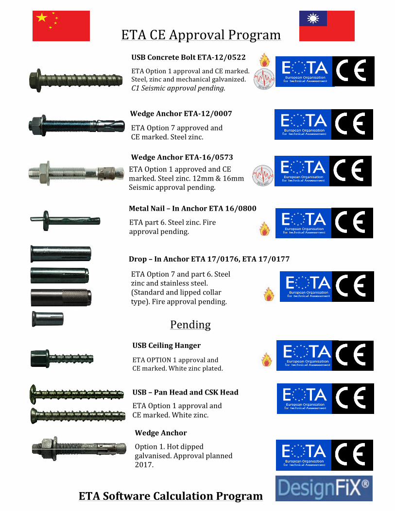
Trade name of the construction product USB ANCHOR
Product family to which the construction product belongs
Concrete screw made of zinc plated steel of sizes 8, 10, 12 and 14 for use in concrete
Manufacturer CONSTRUCTION ANCHORS INC. 7F-1 No. 388, SEC. 1, Nei Hui Road Taipei 114 Taiwan
Manufacturing plant Manufacturing Plant no. 1
This European Technical Assessment contains
13 pages including 3 Annexes which form an integral part of this assessment
This European Technical Assessment is issued in accordance with Regulation (EU) No 305/2011, on the basis of
Guideline for European Technical Approval ETAG 001, Edition April 2013 “Metal anchors for use in concrete – Part 1: Anchors in general and Part 3: Undercut anchors”, used as European Assessment Document (EAD)
This version replaces ETA-12/0522 issued on 12/06/2013
®
Designated according
to Article 29 of
Regulation (EU) No 305/2011
and member of EOTA
(European Organisation for
Technical Assessment)

Page 2 of European Technical Assessment ETA-12/0522, issued on 25/02/2015
This European Technical Assessment is issued by the Technical Assessment Body in its official language. Translations of this European Technical Assessment in other languages shall fully correspond to the original issued document and should be identified as such.
Communication of this European Technical Assessment, including transmission by electronic means, shall be in full. However, partial reproduction may be made, with the written consent of the issuing Technical Assessment Body. Any partial reproduction has to be identified as such.

Page 3 of European Technical Assessment ETA-12/0522, issued on 25/02/2015
Specific Part
1 Technical description of the product
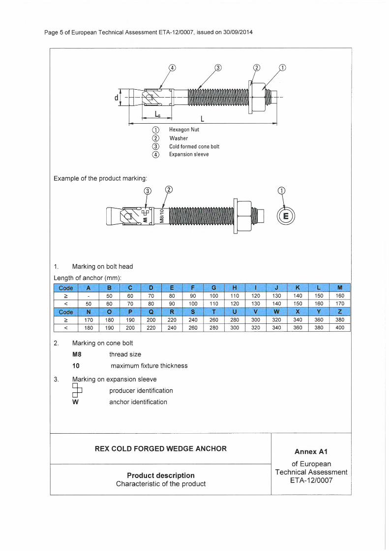
The concrete screw USB ANCHOR of the sizes 8, 10, 12 and 14 is made of heat treated and zinc plated steel (electroplated or mechanically deposited). The anchor is screwed into a predrilled cylindrical drill hole. The special thread of the anchor cuts an internal thread into a concrete member while setting. The anchorage is characterized by mechanical interlock in the special thread.
The description of the product is given in Annex A1 to A2.
2 Specification of the intended use in accordance with the applicable European Assessment Document (EAD)
The performances given in Section 3 are only valid if the anchors are used in compliance with the specifications and conditions given in Annex B1 to B3.
The performances given in this European Technical Assessment are based on an assumed working life of the anchor of 50 years. The indications given on the working life cannot be interpreted as a guarantee given by the producer or the Technical Assessment Body, but are to be regarded only as a means for choosing the right products in relation to the expected economically reasonable working life of the works.
3 Performance of the product and references to the methods used for its assessment
3.1 Performance of the product
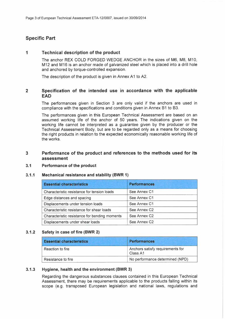
3.1.1 Mechanical resistance and stability (BWR 1)
Essential characteristics Performances
Characteristic resistance for tension loads See Annex C1
Edge distances and spacing See Annex C1
Displacements under tension loads See Annex C1
Characteristic resistance for shear loads See Annex C2
Characteristic resistance for bending moments See Annex C2
Displacements under shear loads See Annex C2
3.1.2 Safety in case of fire (BWR 2)
Essential characteristics Performances
Reaction to fire Anchors satisfy requirements for Class A1
Resistance to fire See Annexes C3 and C4

Page 4 of European Technical Assessment ETA-12/0522, issued on 25/02/2015
3.1.3 Hygiene, health and the environment (BWR 3)
Regarding the dangerous substances clauses contained in this European Technical Assessment, there may be requirements applicable to the products falling within its scope (e.g. transposed European legislation and national laws, regulations and administrative provisions). In order to meet the provisions of the Construction Products Regulation, these requirements need also to be complied with, when and where they apply.
3.1.4 Safety in use (BWR 4)
For Basic Requirement Safety in use the same criteria are valid as for Basic Requirement Mechanical resistance and stability (BWR 1).
3.1.5 Sustainable use of natural resources (BWR 7)
No performance determined.
3.1.6 General aspects relating to fitness for use
Durability and serviceability are only ensured if the specifications of intended use according to Annex B1 are kept.
3.2 Methods used for the assessment
The assessment of fitness of the anchors for the intended use in relation to the requirements for mechanical resistance and stability and safety in use in the sense of the Basic Requirements 1 and 4 has been made in accordance with the ETAG 001 “Metal anchors for use in concrete”, Part 1: “Anchors in general” and Part 3: “Undercut anchors”, on the basis of Option 1.
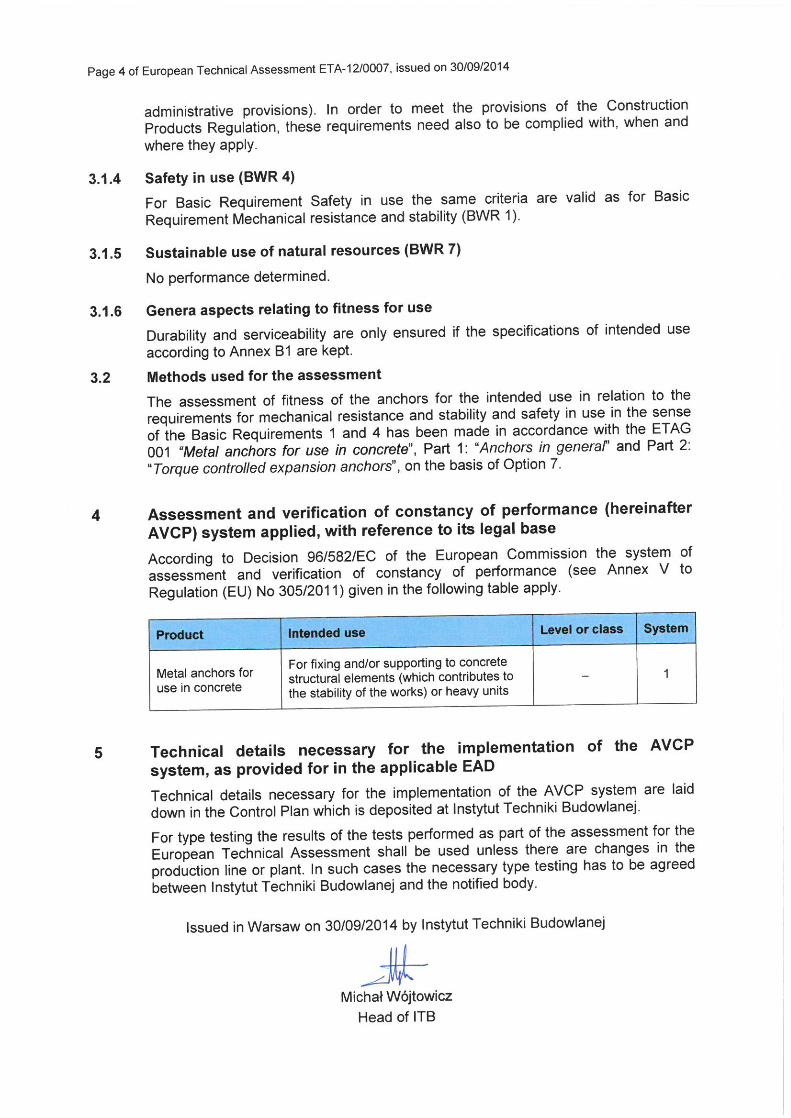
4 Assessment and verification of constancy of performance (AVCP) system applied, with reference to its legal base
According to Decision 96/582/EC of the European Commission the system of assessment and verification of constancy of performance (see Annex V to Regulation (EU) No 305/2011) given in the following table apply.
Product Intended use Level or class System
Metal anchors for use in concrete
For fixing and/or supporting to concrete structural elements (which contributes to the stability of the works) or heavy units
− 1
5 Technical details necessary for the implementation of the AVCP system, as provided for in the applicable European Assessment Document (EAD)
Technical details necessary for the implementation of the AVCP system are laid down in the Control Plan which is deposited at Instytut Techniki Budowlanej.
For type testing the results of the tests performed as part of the assessment for the European Technical Assessment shall be used unless there are changes in the production line or plant. In such cases the necessary type testing has to be agreed between Instytut Techniki Budowlanej and the notified body.
Issued in Warsaw on 25/02/2015 by Instytut Techniki Budowlanej
Marcin M. Kruk, Dr. Eng. Director of ITB

Page 5 of European Technical Assessment ETA-12/0522, issued on 25/02/2015
USB ANCHOR Annex A1
of European Technical Assessment
ETA-12/0522 Product description
Characteristic of the product

Page 6 of European Technical Assessment ETA-12/0522, issued on 25/02/2015
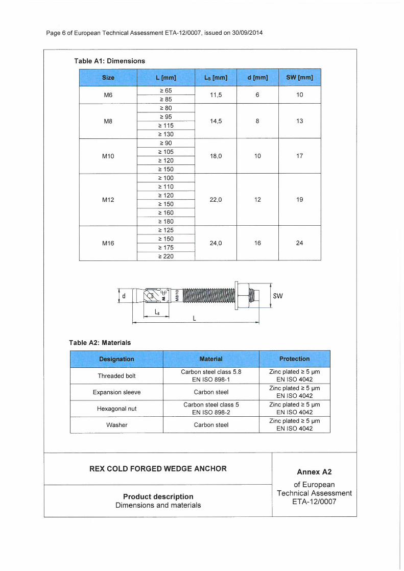
Table A1: Dimensions and materials
Anchor size 8 10 12 14
Length of anchor L Lmin mm 50 55 55 65
Lmax mm 250 350 350 350
Bolt diameter Ødk mm 7.50 9.37 11.35 13.20
Higher thread diameter Ød1 mm 9.85 11.95 14.08 16.23
Lower thread diameter Ød2 mm 8.13 10.25 12.15 14.18
Thread pitch ht mm 10 12 12 17
hs mm 5 5 5 5
Materials Steel 10B21 acc. to SAE-J403 Zinc coating (≥ 5 µm); electroplated acc. to EN ISO 4042 or mechanically deposited acc. to EN ISO 12683
Table A2: Head types with marking
Hex Flange Head
Marking: Identifying mark of the producer: d X L where: d = anchor size [mm] e.g. 8 L = length of anchor [mm] e.g. 100
Countersunk Torx Head
Marking: Identifying mark of the producer: d X L where: d = anchor size [mm] e.g. 10 L = length of anchor [mm] e.g. 120
Hex Head
Marking: Identifying mark of the producer: d X L where: d = anchor size [mm] e.g. 12 L = length of anchor [mm] e.g. 130
USB ANCHOR Annex A2
of European Technical Assessment
ETA-12/0522 Product description
Dimensions, materials and head types

Page 7 of European Technical Assessment ETA-12/0522, issued on 25/02/2015
USB ANCHOR Annex B1
of European Technical Assessment
ETA-12/0522 Intended use Specification
SPECIFICATION OF INTENDED USE
Anchorages subject to: � Static and quasi-static loads: sizes from 8 to 14. � Fire exposure: sizes from 8 to 14.
Base material: � Reinforced or unreinforced normal weight concrete of strength class C20/25 at minimum to
C50/60 at maximum according to EN 206. � Non cracked concrete: sizes from 8 to 14. � Cracked concrete: sizes from 8 to 14.
Use conditions (environmental conditions): � Structures subject to dry internal conditions.
Design: � Anchorages are designed under the responsibility of an engineer experienced in anchorages
and concrete work. � Verifiable calculation notes and drawings are prepared taking account of the loads to be
transmitted. The position of the anchor is indicated on the design drawings (e.g. position of the anchor relative to reinforcement or to supports, etc.).
� Anchorages under static and quasi-static loads are designed in accordance with ETAG 001, Annex C, design method A.
� Anchorages under fire exposure are designed in accordance with EOTA Technical Report TR 020.
Installation: � Anchor installation carried out by appropriately qualified personnel and under the supervision of
the person responsible for technical matters of the site. � Anchor installation in accordance with the manufacturer's specifications and drawings and using
the appropriate tools. � Check of concrete being well compacted, e.g. without significant voids. � Positioning of the drill holes without damaging the reinforcement. � Anchor installation such that the effective anchorage depth is complied with.

Page 8 of European Technical Assessment ETA-12/0522, issued on 25/02/2015
USB ANCHOR Annex B2
of European Technical Assessment
ETA-12/0522 Intended use
Installation parameters
Table B1: Installation parameters
Anchor size 8 10 12 14
Nominal drill bit diameter d0 mm 8 10 12 14
Cutting diameter of drill bit dcut ≤ mm 8.45 10.45 12.50 14.50
Depth of drill hole h1 ≥ mm 55 60 75 60 70 85 60 70 105 70 80 125
Nominal anchorage depth hnom mm 45 50 65 50 60 75 50 60 95 60 70 115
Clearance hole in the fixture df mm 12 14 16 18
Table B2: Minimum thickness of concrete member, minimum spacing and minimum edge distance
Anchor size 8 10 12 14
Minimum thickness of member hmin mm 110 110 130 150
Minimum edge distance cmin mm 60 70 80 90
Minimum spacing smin mm 60 70 80 90
Page 9 of European Technical Assessment ETA-12/0522, issued on 25/02/2015
USB ANCHOR Annex B3
of European Technical Assessment
ETA-12/0522 Intended use
Installation instruction
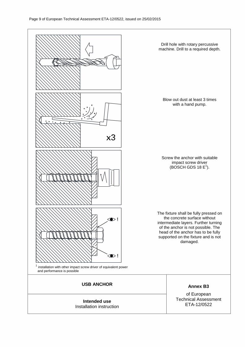
1 installation with other impact screw driver of equivalent power and performance is possible
Drill hole with rotary percussive machine. Drill to a required depth.
Blow out dust at least 3 times with a hand pump.
Screw the anchor with suitable impact screw driver
(BOSCH GDS 18 E1).
The fixture shall be fully pressed on the concrete surface without
intermediate layers. Further turning of the anchor is not possible. The head of the anchor has to be fully supported on the fixture and is not
damaged.

Page 10 of European Technical Assessment ETA-12/0522, issued on 25/02/2015
USB ANCHOR Annex C1
of European Technical Assessment
ETA-12/0522 Performances
Characteristic resistance for tension loads. Displacements
Table C1: Characteristic resistance for tension loads in cracked and non-cracked concrete C20/25 to C50/60 (design acc. to ETAG 001, Annex C, design method A)
Anchor size 8 10 12 14
Nominal anchorage depth hnom [mm] 45 50 65 50 60 75 50 60 95 60 70 115
Steel failure
Characteristic resistance NRk,s [kN] 42,4 67,2 99,4 134,0
Partial safety factor γMs1) 1,4
Pullout failure
Characteristic resistance in non-cracked concrete C20/25
NRk,p [kN] 6 6 12 6 9 16 6 9 25 9 12 35
Characteristic resistance in cracked concrete C20/25 NRk,p [kN] 3 4 7,5 4 6 9 4 6 16 5 7,5 20
Increasing factors for NRk,p
C30/37 1,17 1,17 1,17 1,22
Ψc C40/50 1,32 1,32 1,32 1,41
C50/60 1,42 1,42 1,42 1,55
Partial safety factor for cracked and non-cracked concrete γMp
1) 1,8
Concrete cone and splitting failure
Effective anchorage depth hef [mm] 30 34 47 33 42 54 33 42 71 40 48 86
Spacing scr,N [mm] 90 102 141 100 124 162 100 124 213 118 144 258
Edge distance ccr,N [mm] 45 51 71 50 62 81 50 62 107 59 72 129
Spacing scr,sp [mm] 90 102 141 100 124 162 100 124 213 118 144 258
Edge distance ccr,sp [mm] 45 51 71 50 62 81 50 62 107 59 72 129
1) in the absence of other national regulations
Table C2: Displacements under tension loads
Anchor size 8 10 12 14
Non-cracked concrete C20/25 to C50/60
Tension load N [kN] 5,8 8,5 12,6 15,6
Displacement δ NO [mm] 0,3 0,4 0,4 0,6
δ N∞ [mm] 1,4 1,5 1,8 1,9
Cracked concrete C20/25 to C50/60
Tension load N [kN] 3,2 4,0 6,9 9,6
Displacement δ N0 [mm] 0,4 0,5 0,5 0,6
δ N∞ [mm] 2,0 2,0 2,0 2,0
Page 11 of European Technical Assessment ETA-12/0522, issued on 25/02/2015
USB ANCHOR Annex C2
of European Technical Assessment
ETA-12/0522 Performances
Characteristic resistance for shear loads. Displacements
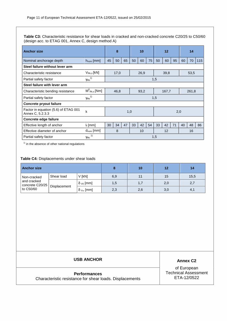
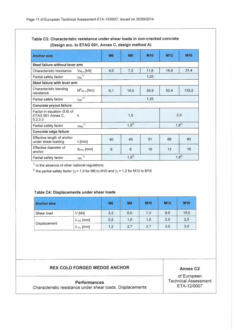
Table C3: Characteristic resistance for shear loads in cracked and non-cracked concrete C20/25 to C50/60 (design acc. to ETAG 001, Annex C, design method A)
Anchor size 8 10 12 14
Nominal anchorage depth hnom [mm] 45 50 65 50 60 75 50 60 95 60 70 115
Steel failure without lever arm
Characteristic resistance VRk,s [kN] 17,0 26,9 39,8 53,5
Partial safety factor γMs1) 1,5
Steel failure with lever arm
Characteristic bending resistance M0Rk,s [Nm] 46,8 93,2 167,7 261,8
Partial safety factor γMs1) 1,5
Concrete pryout failure
Factor in equation (5.6) of ETAG 001 Annex C, 5.2.3.3 k 1,0 2,0
Concrete edge failure
Effective length of anchor lf [mm] 30 34 47 33 42 54 33 42 71 40 48 86
Effective diameter of anchor dnom [mm] 8 10 12 16
Partial safety factor γMc1) 1,5
1) in the absence of other national regulations
Table C4: Displacements under shear loads
Anchor size 8 10 12 14
Non-cracked and cracked concrete C20/25 to C50/60
Shear load V [kN] 6,9 11 15 15,5
Displacement δ V0 [mm] 1,5 1,7 2,0 2,7
δ V∞ [mm] 2,3 2,6 3,0 4,1

Page 12 of European Technical Assessment ETA-12/0522, issued on 25/02/2015
USB ANCHOR Annex C3
of European Technical Assessment
ETA-12/0522 Performances
Characteristic resistance for tension loads under fire exposure
Table C5: Characteristic resistance for tension loads under fire exposure in cracked and non-cracked concrete C20/25 to C50/60 (acc. to TR020)
Anchor size 8 10 12 14
Nominal anchorage depth hnom [mm] 65 75 95 115
Steel failure
Characteristic resistance
R30 NRk,s,fi [kN] 0,64 1,34 1,99 2,68
R60 NRk,s,fi [kN] 0,55 1,01 1,49 2,01
R90 NRk,s,fi [kN] 0,42 0,87 1,29 1,74
R120 NRk,s,fi [kN] 0,34 0,67 0,99 1,34
Pullout failure
Characteristic resistance
R30 NRk,p,fi [kN] 1,9 2,2 4,0 5,0
R60 NRk,p,fi [kN] 1,9 2,2 4,0 5,0
R90 NRk,p,fi [kN] 1,9 2,2 4,0 5,0
R120 NRk,p,fi [kN] 1,5 1,8 3,2 4,0
Concrete cone failure
Characteristic resistance
R30 NRk,c,fi [kN] 2,7 3,9 7,6 12,3
R60 NRk,c,fi [kN] 2,7 3,9 7,6 12,3
R90 NRk,c,fi [kN] 2,7 3,9 7,6 12,3
R120 NRk,c,fi [kN] 2,2 3,1 6,1 9,9
Edge distance
R30 ccr,N,fi [mm]
2 · hef R60 ccr,N,fi [mm]
R90 ccr,N,fi [mm]
R120 ccr,N,fi [mm]
Spacing
R30 scr,N,fi [mm]
4 · hef R60 scr,N,fi [mm]
R90 scr,N,fi [mm]
R120 scr,N,fi [mm]
Page 13 of European Technical Assessment ETA-12/0522, issued on 25/02/2015
USB ANCHOR Annex C4
of European Technical Assessment
ETA-12/0522 Performances
Characteristic resistance for shear loads under fire exposure
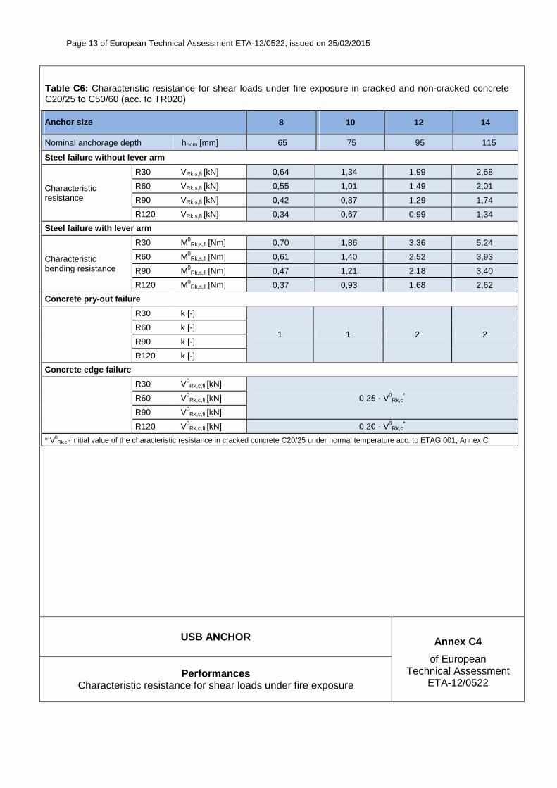
Table C6: Characteristic resistance for shear loads under fire exposure in cracked and non-cracked concrete C20/25 to C50/60 (acc. to TR020)
Anchor size 8 10 12 14
Nominal anchorage depth hnom [mm] 65 75 95 115
Steel failure without lever arm
Characteristic resistance
R30 VRk,s,fi [kN] 0,64 1,34 1,99 2,68
R60 VRk,s,fi [kN] 0,55 1,01 1,49 2,01
R90 VRk,s,fi [kN] 0,42 0,87 1,29 1,74
R120 VRk,s,fi [kN] 0,34 0,67 0,99 1,34
Steel failure with lever arm
Characteristic bending resistance
R30 M0Rk,s,fi [Nm] 0,70 1,86 3,36 5,24
R60 M0Rk,s,fi [Nm] 0,61 1,40 2,52 3,93
R90 M0Rk,s,fi [Nm] 0,47 1,21 2,18 3,40
R120 M0Rk,s,fi [Nm] 0,37 0,93 1,68 2,62
Concrete pry-out failure
R30 k [-]
1 1 2 2 R60 k [-]
R90 k [-]
R120 k [-]
Concrete edge failure
R30 V0Rk,c,fi [kN]
0,25 · V0Rk,c
* R60 V0Rk,c,fi [kN]
R90 V0Rk,c,fi [kN]
R120 V0Rk,c,fi [kN] 0,20 · V0
Rk,c*
* V0Rk,c - initial value of the characteristic resistance in cracked concrete C20/25 under normal temperature acc. to ETAG 001, Annex C

Centre Scientifique et
Technique du Bâtiment 84 avenue Jean Jaurès CHAMPS-SUR-MARNE F-77447 Marne-la-Vallée Cedex 2Tél. : (33) 01 64 68 82 82Fax : (33) 01 60 05 70 37
Member of
www.eota.eu
European Technical Assessment
ETA-16/0573 dated 01/08/2016
English translation prepared by CSTB - Original version in French language
General Part
Nom commercial Trade name
CT Bolt 1
Famille de produit Product family
Cheville métallique à expansion par vissage à couple contrôlé, de fixation dans le béton fissuré et non fissuré diamètres M8, M10, M12 et M16
Torque-controlled expansion anchor for use in cracked and uncracked concrete: sizes M8, M10, M12 and M16
Titulaire Manufacturer
Construction Anchors Co. Ltd. 9F, No.21, Sec. 3, Xinsheng S. Rd., Da’an Dist, Taipei City 106, Taiwan. R.O.C.
Usine de fabrication Manufacturing plants
Plant 1
Cette evaluation contient: This Assessment contains
16 pages incluant 12 annexes qui font partie intégrante de cette évaluation 16 pages including 12 annexes which form an integral part of this assessment
Base de l‘ETE Basis of ETA
ETAG 001, Version Avril 2013, utilisée en tant que EAD
ETAG 001, Edition April 2013 used as EAD
Translations of this European Technical Assessment in other languages shall fully correspond to the original issued document and should be identified as such. Communication of this European Technical Assessment, including transmission by electronic means, shall be in full. However, partial reproduction may be made, with the written consent of the issuing Technical Assessment Body. Any partial reproduction has to be identified as such..

European technical assessment ETA-1 6 / 0 5 7 3
English translation prepared by CSTB
Page 2 sur 16 | 0 1 / 0 8 / 2 0 1 6
Specific Part
1 Technical description of the product
The CT Bolt 1 anchor is an anchor made of zinc electroplated steel which is placed into a drilled hole and anchored by torque-controlled expansion.
The anchor is placed into a drilled hole and anchored by torque-controlled expansion.
The illustration and the description of the product are given in Annexes A.
2 Specification of the intended use
The performances given in Section 3 are only valid if the anchor is used in compliance with the specifications and conditions given in Annexes B.
The provisions made in this European technical assessment are based on an assumed working life of the anchor of 50 years. The indications given on the working life cannot be interpreted as a guarantee given by the producer, but are to be regarded only as a means for choosing the right products in relation to the expected economically reasonable working life of the works.
3 Performance of the product
3.1 Mechanical resistance and stability (BWR 1)
Essential characteristic Performance
Characteristic tension resistance acc. ETAG001, Annex C See Annex C1
Characteristic shear resistance acc. ETAG001, Annex C See Annex C2
Characteristic tension resistance acc. CEN/TS 1992-4 See Annex C5
Characteristic shear resistance acc. CEN/TS 1992-4 See Annex C6
Displacements See Annex C9
3.2 Safety in case of fire (BWR 2)
Essential characteristic Performance
Reaction to fire Anchorages satisfy requirements for Class A1
Characteristic tension resistance under fire acc. ETAG001, Annex C
See Annex C3
Characteristic shear resistance under fire acc. ETAG001, Annex C
See Annex C4
Characteristic tension resistance under fire acc. CEN/TS 1992-4
See Annex C7
Characteristic shear resistance under fire acc. CEN/TS 1992-4
See Annex C8
3.3 Hygiene, health and the environment (BWR 3)
Regarding dangerous substances contained in this European technical approval, there may be requirements applicable to the products falling within its scope (e.g. transposed European legislation and national laws, regulations and administrative provisions). In order to meet the provisions of the Construction Products Directive, these requirements need also to be complied with, when and where they apply.
European technical assessment ETA-1 6 / 0 5 7 3
English translation prepared by CSTB
Page 3 sur 16 | 0 1 / 0 8 / 2 0 1 6
3.4 Safety in use (BWR 4)
For Basic requirement Safety in use the same criteria are valid as for Basic Requirement Mechanical resistance and stability.
3.5 Protection against noise (BWR 5)
Not relevant.
3.6 Energy economy and heat retention (BWR 6)
Not relevant.
3.7 Sustainable use of natural resources ( (BWR 7)
For the sustainable use of natural resources no performance was determined for this product.
3.8 General aspects relating to fitness for use
Durability and Serviceability are only ensured if the specifications of intended use according to Annex B1 are kept.
4 Assessment and verification of constancy of performance (AVCP)
According to the Decision 96/582/EC of the European Commission1, as amended, the system of
assessment and verification of constancy of performance (see Annex V to Regulation (EU) No 305/2011) given in the following table apply.
Product Intended use Level or class System
Metal anchors for use in concrete
For fixing and/or supporting to concrete, structural elements (which contributes to the stability of the works) or heavy units
― 1
5 Technical details necessary for the implementation of the AVCP system
Technical details necessary for the implementation of the Assessment and verification of constancy of performance (AVCP) system are laid down in the control plan deposited at Centre Scientifique et Technique du Bâtiment.
The manufacturer shall, on the basis of a contract, involve a notified body approved in the field of anchors for issuing the certificate of conformity CE based on the control plan.
The original French version is signed by
Charles Baloche
Technical Director
1 Official Journal of the European Communities L 254 of 08.10.1996
European technical assessment ETA-1 6 / 0 5 7 3 English translation prepared by CSTB
Page 4 sur 16 | 0 1 / 0 8 / 2 0 1 6
CT Bolt 1
Annex A1
Product descripion
Installation conditions
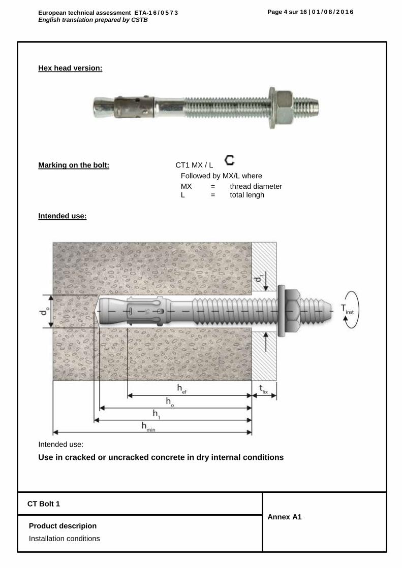
Hex head version:
Marking on the bolt: CT1 MX / L
Followed by MX/L where
MX = thread diameter L = total lengh
Intended use:
Intended use:
Use in cracked or uncracked concrete in dry internal conditions

European technical assessment ETA-1 6 / 0 5 7 3 English translation prepared by CSTB
Page 5 sur 16 | 0 1 / 0 8 / 2 0 1 6
CT Bolt 1
Annex A2
Product descripion
Material
Different parts of the anchor:
Table 1: Materials
Part Designation Material Protection
1 Thread bolt Coldform steel, grade C-1035 Zinc plated 5 m
2 Expansion clip Stainless steel -
3 Washer DIN 125 or EN ISO 7089
DIN 9021 or DIN 440 or D IN EN ISO 7093 Zinc plated
4 Hexagonal nut Property class 8 acc. To DIN 267-4 Zinc plated
European technical assessment ETA-1 6 / 0 5 7 3 English translation prepared by CSTB
Page 6 sur 16 | 0 1 / 0 8 / 2 0 1 6
CT Bolt 1
Annex B1
Intended Use
Specifications
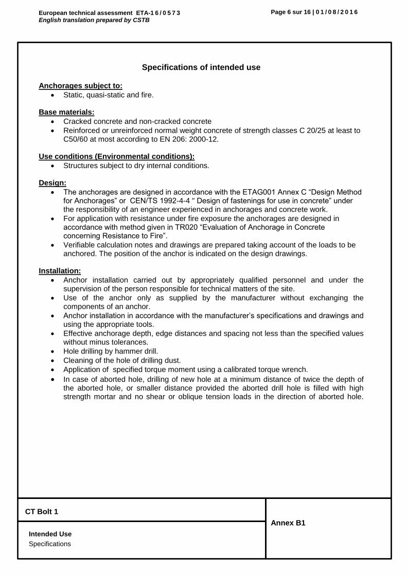
Specifications of intended use
Anchorages subject to:
Static, quasi-static and fire.
Base materials:
Cracked concrete and non-cracked concrete
Reinforced or unreinforced normal weight concrete of strength classes C 20/25 at least to C50/60 at most according to EN 206: 2000-12.
Use conditions (Environmental conditions):
Structures subject to dry internal conditions. Design:
The anchorages are designed in accordance with the ETAG001 Annex C “Design Method for Anchorages” or CEN/TS 1992-4-4 " Design of fastenings for use in concrete” under the responsibility of an engineer experienced in anchorages and concrete work.
For application with resistance under fire exposure the anchorages are designed in accordance with method given in TR020 “Evaluation of Anchorage in Concrete concerning Resistance to Fire”.
Verifiable calculation notes and drawings are prepared taking account of the loads to be anchored. The position of the anchor is indicated on the design drawings.
Installation:
Anchor installation carried out by appropriately qualified personnel and under the supervision of the person responsible for technical matters of the site.
Use of the anchor only as supplied by the manufacturer without exchanging the components of an anchor.
Anchor installation in accordance with the manufacturer’s specifications and drawings and using the appropriate tools.
Effective anchorage depth, edge distances and spacing not less than the specified values without minus tolerances.
Hole drilling by hammer drill.
Cleaning of the hole of drilling dust.
Application of specified torque moment using a calibrated torque wrench.
In case of aborted hole, drilling of new hole at a minimum distance of twice the depth of the aborted hole, or smaller distance provided the aborted drill hole is filled with high strength mortar and no shear or oblique tension loads in the direction of aborted hole.

European technical assessment ETA-1 6 / 0 5 7 3 English translation prepared by CSTB
Page 7 sur 16 | 0 1 / 0 8 / 2 0 1 6
CT Bolt 1
Annex B2
Intended Use
Installation parameters
Table 2: Anchor dimensions
M8 M10 M12 M16
Length of the anchor Min.
L [mm] 60 85 90 115
Max. [mm] 240 220 220 220
Fixture thickness Min.
tfix [mm] 1 1 1 1
Max. [mm] 185 140 130 100
Length expansion sleeve lclip [mm] 14 18 22 26
Width torque wrench SW [mm] 13 17 19 24
Table 3: Installation data
M8 M10 M12 M16
Drill hole diameter dcut [mm] ≤ 8,45 ≤ 10,45 ≤ 12,5 ≤ 16,5
Drill hole depth h1 [mm] 55 75 75 100
Embedment depth hef [mm] 40 60 60 80
Installation torque Tinst [Nm] 30 50 70 130
Diameter through hole fixture df [mm] 9 12 14 18
Min. member thickness hmin [mm] 100 120 120 160
Minimum edge distance cmin [mm] 65 60 80 85
Minimum spacing smin [mm] 65 150 80 85

European technical assessment ETA-1 6 / 0 5 7 3 English translation prepared by CSTB
Page 8 sur 16 | 0 1 / 0 8 / 2 0 1 6
CT Bolt 1
Annex C1 Design according to ETAG001, Annex C
Characteristic resistance under tension loads
Table 4: Characteristic values for tension loads in case of static and quasi static loading
for design method A acc. ETAG001, Annex C
M8 M10 M12 M16
Steel failure
Char. resistance NRk,s [kN] 22,2 31,6 43,4 75,4
Partial safety factor Ms1) [-] 1,88 1,88 1,88 1,88
Pullout failure NRk,p = c x N0Rk,p
Char. resistance in concrete C20/25
cracked N0Rk,p [kN] 3 9 12 12
non-cracked N0Rk,p [kN] 6 12 12 35
Partial safety factor for cracked or non-cracked concrete Mp
1) [-] 1,8 3) 1,8 3) 2,12) 2,12)
Increasing factor for NRK
concrete C30/37
c
[-] 1,22 1,22 1,22 1,22
concrete C40/50 [-] 1,41 1,41 1,41 1,41
concrete C50/60 [-] 1,55 1,55 1,55 1,55
Concrete cone failure and splitting failure
Effective embedment depth hef [mm] 40 60 60 80
Partial safety factor for craked or non-cracked concrete Mc=Msp
1) [-] 1,8 3) 1,8 3) 2,12) 2,12)
Increasing factor for NRK
concrete C30/37 [-] 1,22 1,22 1,22 1,22
concrete C40/50 c [-] 1,41 1,41 1,41 1,41
concrete C50/60 [-] 1,55 1,55 1,55 1,55
Char. spacing concrete cone failure scr,N [mm] 120 180 180 240
splitting failure scr,sp [mm] 200 300 360 400
Char. edge distance concrete cone failure ccr,N [mm] 60 90 90 120
splitting failure ccr,sp [mm] 100 150 180 200
1) In absence of other national regulations
2) The value contains an installation safety factor 2= 1.4
3) The value contains an installation safety factor 2= 1.2

European technical assessment ETA-1 6 / 0 5 7 3 English translation prepared by CSTB
Page 9 sur 16 | 0 1 / 0 8 / 2 0 1 6
CT Bolt 1
Annex C2 Design according to ETAG001, Annex C
Characteristic resistance under shear loads
Table 5: Characteristic values for shear loads in case of static and quasi static loading for
design method A acc. ETAG001, Annex C
M8 M10 M12 M16
Steel failure without lever arm
Char. resistance VRk,s [kN] 8,1 17,6 24,7 45,9
Partial safety factor Ms1) [-] 1,25 1,25 1,25 1,25
Steel failure with lever arm
Char. bending resistance M0Rk,s [Nm] 22,8 45,5 76,6 194,8
Partial safety factor Ms1) [-] 1,25 1,25 1,25 1,25
Concrete pry-out failure
Factor in equation (5.6) of ETAG Annex C, § 5.2.3.3
k [-] 1,0 2,0 2,0 2,0
Partial safety factor Mc1) [-] 1,5 1,5 1,5 1,5
Concrete edge failure
Effective length of anchor under shear loading
lf [mm] 40 60 60 80
Outside diameter of anchor dnom [mm] 8 10 12 16
Partial safety factor Mc1) [-] 1,5 1,5 1,5 1,5
1) In absence of other national regulations
European technical assessment ETA-1 6 / 0 5 7 3 English translation prepared by CSTB
Page 10 sur 16 | 0 1 / 0 8 / 2 0 1 6
CT Bolt 1
Annex C3
Design according to ETAG001, Annex C
Characteristic tension resistance under fire exposure
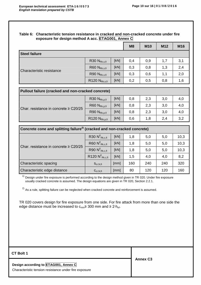
Table 6: Characteristic tension resistance in cracked and non-cracked concrete under fire
exposure for design method A acc. ETAG001, Annex C
M8 M10 M12 M16
Steel failure
Characteristic resistance
R30 NRk,s,fi [kN] 0,4 0,9 1,7 3,1
R60 NRk,s,fi [kN] 0,3 0,8 1,3 2,4
R90 NRk,s,fi [kN] 0,3 0,6 1,1 2,0
R120 NRk,s,fi [kN] 0,2 0,5 0,8 1,6
Pullout failure (cracked and non-cracked concrete)
Char. resistance in concrete ≥ C20/25
R30 NRk,p,fi [kN] 0,8 2,3 3,0 4,0
R60 NRk,p,fi [kN] 0,8 2,3 3,0 4,0
R90 NRk,p,fi [kN] 0,8 2,3 3,0 4,0
R120 NRk,p,fi [kN] 0,6 1,8 2,4 3,2
Concrete cone and splitting failure2) (cracked and non-cracked concrete)
Char. resistance in concrete ≥ C20/25
R30 N0Rk,c,fi [kN] 1,8 5,0 5,0 10,3
R60 N0Rk,c,fi [kN] 1,8 5,0 5,0 10,3
R90 N0Rk,c,fi [kN] 1,8 5,0 5,0 10,3
R120 N0Rk,c,fi [kN] 1,5 4,0 4,0 8,2
Characteristic spacing scr,N,fi [mm] 160 240 240 320
Characteristic edge distance ccr,N,fi [mm] 80 120 120 160
1) Design under fire exposure is performed according to the design method given in TR 020. Under fire exposure
usually cracked concrete is assumed. The design equations are given in TR 020, Section 2.2.1.
2) As a rule, splitting failure can be neglected when cracked concrete and reinforcement is assumed.
TR 020 covers design for fire exposure from one side. For fire attack from more than one side the edge distance must be increased to cmin≥ 300 mm and ≥ 2∙hef.
European technical assessment ETA-1 6 / 0 5 7 3 English translation prepared by CSTB
Page 11 sur 16 | 0 1 / 0 8 / 2 0 1 6
CT Bolt 1
Annex C4
Design according to ETAG001, Annex C
Characteristic shear resistance under fire exposure
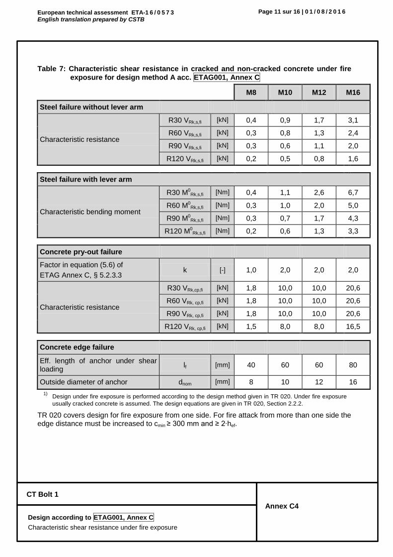
Table 7: Characteristic shear resistance in cracked and non-cracked concrete under fire
exposure for design method A acc. ETAG001, Annex C
M8 M10 M12 M16
Steel failure without lever arm
Characteristic resistance
R30 VRk,s,fi [kN] 0,4 0,9 1,7 3,1
R60 VRk,s,fi [kN] 0,3 0,8 1,3 2,4
R90 VRk,s,fi [kN] 0,3 0,6 1,1 2,0
R120 VRk,s,fi [kN] 0,2 0,5 0,8 1,6
Steel failure with lever arm
Characteristic bending moment
R30 M0Rk,s,fi [Nm] 0,4 1,1 2,6 6,7
R60 M0Rk,s,fi [Nm] 0,3 1,0 2,0 5,0
R90 M0Rk,s,fi [Nm] 0,3 0,7 1,7 4,3
R120 M0Rk,s,fi [Nm] 0,2 0,6 1,3 3,3
Concrete pry-out failure
Factor in equation (5.6) of
ETAG Annex C, § 5.2.3.3 k [-] 1,0 2,0 2,0 2,0
Characteristic resistance
R30 VRk,cp,fi [kN] 1,8 10,0 10,0 20,6
R60 VRk, cp,fi [kN] 1,8 10,0 10,0 20,6
R90 VRk, cp,fi [kN] 1,8 10,0 10,0 20,6
R120 VRk, cp,fi [kN] 1,5 8,0 8,0 16,5
Concrete edge failure
Eff. length of anchor under shear loading
lf [mm] 40 60 60 80
Outside diameter of anchor dnom [mm] 8 10 12 16
1) Design under fire exposure is performed according to the design method given in TR 020. Under fire exposure
usually cracked concrete is assumed. The design equations are given in TR 020, Section 2.2.2.
TR 020 covers design for fire exposure from one side. For fire attack from more than one side the edge distance must be increased to cmin ≥ 300 mm and ≥ 2∙hef.
European technical assessment ETA-1 6 / 0 5 7 3 English translation prepared by CSTB
Page 12 sur 16 | 0 1 / 0 8 / 2 0 1 6
CT Bolt 1
Annex C5
Design according to CEN/TS 1992-4
Characteristic resistance under tension loads
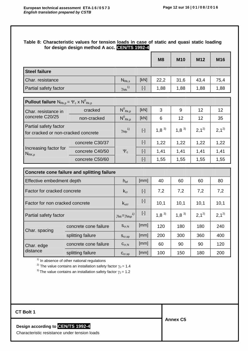
Table 8: Characteristic values for tension loads in case of static and quasi static loading
for design design method A acc. CEN/TS 1992-4
M8 M10 M12 M16
Steel failure
Char. resistance NRk,s [kN] 22,2 31,6 43,4 75,4
Partial safety factor Ms1) [-] 1,88 1,88 1,88 1,88
Pullout failure NRk,p = c x N0Rk,p
Char. resistance in concrete C20/25
cracked N0Rk,p [kN] 3 9 12 12
non-cracked N0Rk,p [kN] 6 12 12 35
Partial safety factor
for cracked or non-cracked concrete Mp
1) [-] 1,8 3) 1,8 3) 2,12) 2,12)
Increasing factor for NRK,p
concrete C30/37
c
[-] 1,22 1,22 1,22 1,22
concrete C40/50 [-] 1,41 1,41 1,41 1,41
concrete C50/60 [-] 1,55 1,55 1,55 1,55
Concrete cone failure and splitting failure
Effective embedment depth hef [mm] 40 60 60 80
Factor for cracked concrete kcr [-] 7,2 7,2 7,2 7,2
Factor for non cracked concrete kucr [-]
10,1 10,1 10,1 10,1
Partial safety factor Mc=Msp1)
[-] 1,8 3) 1,8 3) 2,12) 2,12)
Char. spacing concrete cone failure scr,N [mm] 120 180 180 240
splitting failure scr,sp [mm] 200 300 360 400
Char. edge distance
concrete cone failure ccr,N [mm] 60 90 90 120
splitting failure ccr,sp [mm] 100 150 180 200
1) In absence of other national regulations
2) The value contains an installation safety factor 2 = 1.4
3) The value contains an installation safety factor 2 = 1.2

European technical assessment ETA-1 6 / 0 5 7 3 English translation prepared by CSTB
Page 13 sur 16 | 0 1 / 0 8 / 2 0 1 6
CT Bolt 1
Annex C6
Design according to CEN/TS 1992-4
Characteristic resistance under shear loads
Table 9: Characteristic values for shear loads in case of static and quasi static loading for
design design method A acc. CEN/TS 1992-4
M8 M10 M12 M16
Steel failure without lever arm
Char. resistance VRk,s [kN] 8,1 17,6 24,7 45,9
Factor considering ductility k2 [-] 0,8 0,8 0,8 0,8
Partial safety factor Ms1) [-] 1,25 1,25 1,25 1,25
Steel failure with lever arm
Char. bending moment M0Rk,s [Nm] 22,8 45,5 76,6 194,8
Partial safety factor Ms1) [-] 1,25 1,25 1,25 1,25
Concrete pry-out failure
Factor in equation (16) of CEN/TS 1992-4-4, § 6.2.2.3
k3 [-] 1,0 2,0 2,0 2,0
Partial safety factor Mc1) [-] 1,5 1,5 1,5 1,5
Concrete edge failure
Effective length of anchor under shear loading
lf [mm] 40 60 60 80
Outside diameter of anchor dnom [mm] 8 10 12 16
Partial safety factor Mc1) [-] 1,5 1,5 1,5 1,5
1) In absence of other national regulations

European technical assessment ETA-1 6 / 0 5 7 3 English translation prepared by CSTB
Page 14 sur 16 | 0 1 / 0 8 / 2 0 1 6
CT Bolt 1
Annex C7
Design according to CEN/TS 1992-4
Characteristic tension resistance under fire exposure
Table 10: Characteristic tension resistance in cracked and non-cracked concrete under
fire exposure for design method A acc. CEN/TS 1992-4
M8 M10 M12 M16
Steel failure
Characteristic resistance
R30 NRk,s,fi [kN] 0,4 0,9 1,7 3,1
R60 NRk,s,fi [kN] 0,3 0,8 1,3 2,4
R90 NRk,s,fi [kN] 0,3 0,6 1,1 2,0
R120 NRk,s,fi [kN] 0,2 0,5 0,8 1,6
Pullout failure (cracked and non-cracked concrete)
Char. resistance in concrete ≥ C20/25
R30 NRk,p,fi [kN] 0,8 2,3 3,0 4,0
R60 NRk,p,fi [kN] 0,8 2,3 3,0 4,0
R90 NRk,p,fi [kN] 0,8 2,3 3,0 4,0
R120 NRk,p,fi [kN] 0,6 1,8 2,4 3,2
Concrete cone and splitting failure 2) (cracked and non-cracked concrete)
Char. resistance in concrete ≥ C20/25
R30 N0Rk,c,fi [kN] 1,8 5,0 5,0 10,3
R60 N0Rk,c,fi [kN] 1,8 5,0 5,0 10,3
R90 N0Rk,c,fi [kN] 1,8 5,0 5,0 10,3
R120 N0Rk,c,fi [kN] 1,5 4,0 4,0 8,2
Characteristic spacing scr,N,fi [mm] 160 240 240 320
Characteristic edge distance ccr,N,fi [mm] 80 120 120 160
1) Design under fire exposure is performed according to the design method given in TR 020. Under fire exposure
usually cracked concrete is assumed. The design equations are given in TR 020, Section 2.2.1.
2) As a rule, splitting failure can be neglected when cracked concrete and reinforcement is assumed.
TR 020 covers design for fire exposure from one side. For fire attack from more than one side the edge distance must be increased to cmin≥ 300 mm and ≥ 2∙hef.

European technical assessment ETA-1 6 / 0 5 7 3 English translation prepared by CSTB
Page 15 sur 16 | 0 1 / 0 8 / 2 0 1 6
CT Bolt 1
Annex C8
Design according to CEN/TS 1992-4
Characteristic shear resistance under fire exposure
Table 11: Characteristic shear resistance in cracked and non-cracked concrete under fire
exposure for design method A acc. CEN/TS 1992-4
M8 M10 M12 M16
Steel failure without lever arm
Characteristic resistance
R30 VRk,s,fi [kN] 0,4 0,9 1,7 3,1
R60 VRk,s,fi [kN] 0,3 0,8 1,3 2,4
R90 VRk,s,fi [kN] 0,3 0,6 1,1 2,0
R120 VRk,s,fi [kN] 0,2 0,5 0,8 1,6
Steel failure with lever arm
Characteristic bending moment
R30 M0Rk,s,fi [Nm] 0,4 1,1 2,6 6,7
R60 M0Rk,s,fi [Nm] 0,3 1,0 2,0 5,0
R90 M0Rk,s,fi [Nm] 0,3 0,7 1,7 4,3
R120 M0Rk,s,fi [Nm] 0,2 0,6 1,3 3,3
Concrete pry-out failure
Factor in equation (16) of CEN/TS 1992-4-4, § 6.2.2.3
k3 [-] 1,0 2,0 2,0 2,0
Characteristic resistance
R30 VRk,cp,fi [kN] 1,8 10,0 10,0 20,6
R60 VRk, cp,fi [kN] 1,8 10,0 10,0 20,6
R90 VRk, cp,fi [kN] 1,8 10,0 10,0 20,6
R120 VRk, cp,fi [kN] 1,5 8,0 8,0 16,5
Concrete edge failure
Eff. length of anchor under shear loading
lf [mm] 40 60 60 80
Outside diameter of anchor dnom [mm] 8 10 12 16
1) Design under fire exposure is performed according to the design method given in TR 020. Under fire exposure
usually cracked concrete is assumed. The design equations are given in TR 020, Section 2.2.2.
TR 020 covers design for fire exposure from one side. For fire attack from more than one side the edge distance must be increased to cmin ≥ 300 mm and ≥ 2∙hef.

European technical assessment ETA-1 6 / 0 5 7 3 English translation prepared by CSTB
Page 16 sur 16 | 0 1 / 0 8 / 2 0 1 6
CT Bolt 1
Annex C9 Design
Displacements
Table 12: Displacements under tension loading
M8 M10 M12 M16
Tension load in non-cracked concrete C20/25 [kN] 2,38 4,76 5,44 11,90
Displacement N0 [mm] 0,05 0,10 0,06 0,30
N∞ [mm] 0,65 1,17 1,53 0,65
Tension load in non-cracked concrete C50/60 [kN] 3,69 9,92 10,20 18,45
Displacement N0 [mm] 0,05 0,24 0,10 0,10
N∞ [mm] 0,65 1,17 1,53 0,65
Tension load in cracked concrete C20/25 [kN] 1,19 4,76 4,08 4,08
Displacement N0 [mm] 0,05 0,83 1,04 0,40
N∞ [mm] 1,15 1,17 1,53 1,14
Tension load in cracked concrete C50/60 [kN] 1,85 4,76 10,20 6,33
Displacement N0 [mm] 2,95 0,94 1,89 3,43
N∞ [mm] 2,95 1,17 1,53 3,43
Tableau 13: Displacements under shear loading
M8 M10 M12 M16
Shear load in cracked and non-cracked concrete C20/25 to C50/60
[kN] 4,63 9,14 9,52 26,23
Displacement V0 [mm] 5,50 5,26 5,84 3,60
V∞ [mm] 8,25 7,89 8,76 5,40
Additional displacement due to anular gap between anchor and fixture is to be taken into account.


INSTYTUT TECHNIKI BUDOWLANEJ PL 00-611 WARSZAWA ul. Filtrowa 1 tel.: (+48 22) 825-04-71 (+48 22) 825-76-55 fax: (+48 22) 825-52-86 www.itb.pl
Member of
www.eota.eu
Egzemplarz archiwalny
European Technical Assessment
ETA-17/0325 of 10/04/2017
(English language translation – the original version is in Polish language)
General Part
Technical Assessment Body issuing the European Technical Assessment
Instytut Techniki Budowlanej
Trade name of the construction product CMH ANCHOR
Product family to which the construction product belongs
Deformation-controlled expansion anchor made of galvanized steel for multiple use for non-structural applications in concrete
Manufacturer
Construction Anchors Co., Ltd. 9F, No. 21, Sec. 3, Xinsheng S.Rd., Da’an Dist, Taipei City 106 Taiwan R.O.C.Hong Kong
Manufacturing plant Manufacturing Plant no. 4
This European Technical Assessment contains
9 pages including 3 Annexes which form an integral part of this assessment
This European Technical Assessment is issued in accordance with Regulation (EU) No 305/2011, on the basis of
Guideline for European Technical Approval ETAG 001, Edition April 2013 “Metal anchors for use in concrete – Part 1: Anchors in general and Part 6: Anchors for multiple use for non-structural applications”, used as European Assessment Document (EAD)
®
Designated according
to Article 29 of
Regulation (EU) No 305/2011
and member of EOTA
(European Organisation for
Technical Assessment)

Page 2 of European Technical Assessment ETA-17/0325 issued on 10/04/2017
This European Technical Assessment is issued by the Technical Assessment Body in its official language. Translations of this European Technical Assessment in other languages shall fully correspond to the original issued document and should be identified as such.
Communication of this European Technical Assessment, including transmission by electronic means, shall be in full. However, partial reproduction may be made, with the written consent of the issuing Technical Assessment Body. Any partial reproduction has to be identified as such.

Page 3 of European Technical Assessment ETA-17/0325 issued on 10/04/2017
Specific Part
1 Technical description of the product
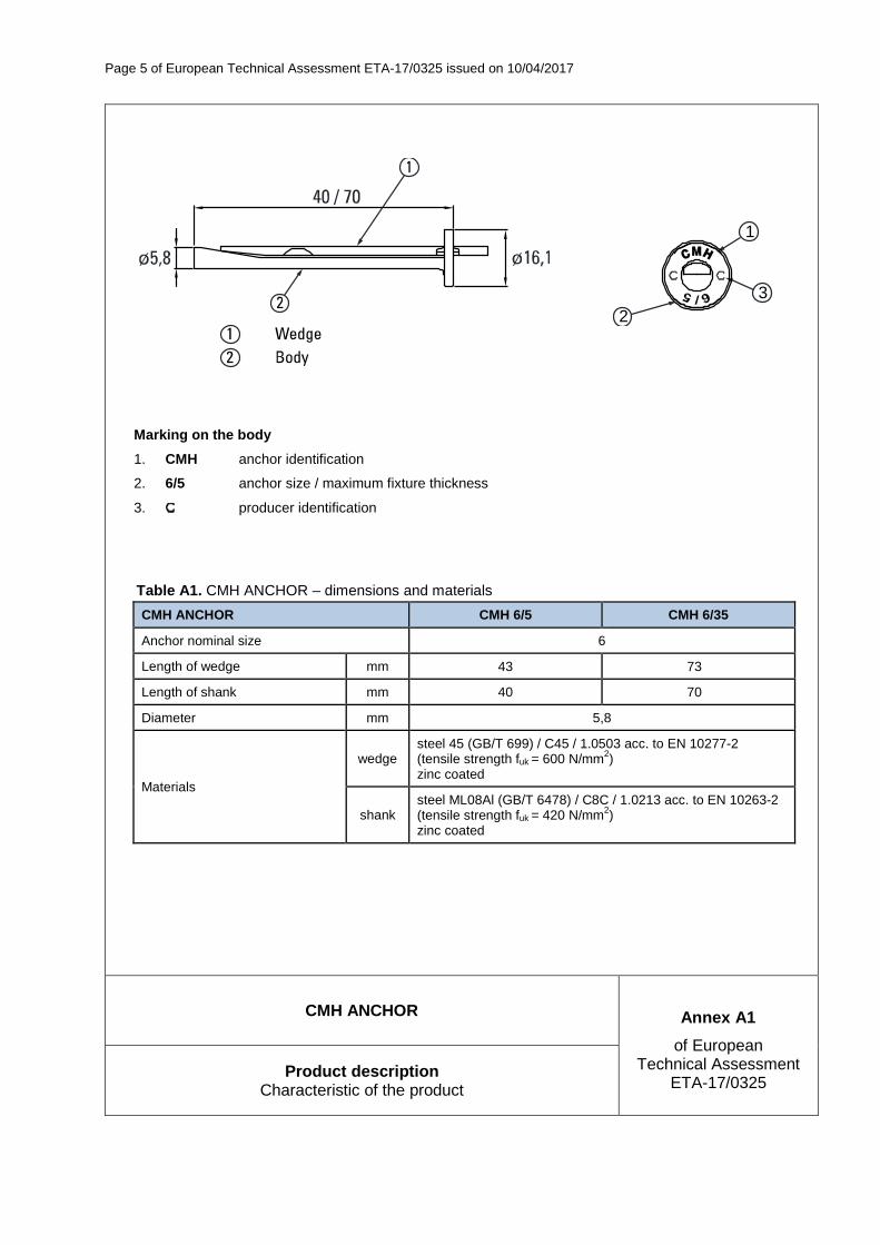
CMH ANCHOR of size Ø6 is deformation-controlled expansion anchor. CMH ANCHOR is made of galvanized steel. The anchor is installed in a drilled hole and anchored by deformation-controlled expansion.
An illustration of the product is given in Annex A1.
2 Specification of the intended use in accordance with the applicable European Assessment Document (EAD)
The performances given in Section 3 are only valid if the anchors are used in compliance with the specifications and conditions given in Annex B1 and B2.
The performances given in this European Technical Assessment are based on an assumed working life of the anchor of 50 years. The indications given on the working life cannot be interpreted as a guarantee given by the producer or the Technical Assessment Body, but are to be regarded only as a means for choosing the right products in relation to the expected economically reasonable working life of the works.
3 Performance of the product and references to the methods used for its assessment
3.1 Performance of the product
3.1.1 Mechanical resistance and stability (BWR 1)
Essential characteristic Performance
Characteristic resistance for all load directions
See Annex C1
Edge distances and spacing See Annex C1
3.1.2 Safety in case of fire (BWR 2)
Essential characteristic Performance
Reaction to fire Anchors satisfy requirements for Class A1
Characteristic resistance under fire exposure See Annex C2
3.1.3 Hygiene, health and the environment (BWR 3)
Regarding the dangerous substances there may be requirements applicable to the products falling within its scope (e.g. transposed European legislation and national laws, regulations and administrative provisions). In order to meet the provisions of the Construction Products Regulation, these requirements need also to be complied with, when and where they apply.
3.1.4 Safety and accessibility in use (BWR 4)
For Basic Requirement Safety in use the same criteria are valid as for Basic Requirement Mechanical resistance and stability (BWR 1).

Page 4 of European Technical Assessment ETA-17/0325 issued on 10/04/2017
3.1.5 Sustainable use of natural resources (BWR 7)
No performance assessed.
3.1.6 General aspects relating to fitness for use
Durability and serviceability are only ensured if the specifications of intended use according to Annex B1 are kept.
3.2 Methods used for the assessment
The assessment of fitness of the anchors for declared intended use in relation to the requirements for mechanical resistance and stability and safety in use in the sense of the Basic Requirements 1 and 4 has been made in accordance with the ETAG 001 “Metal anchors for use in concrete”, Part 1: “Anchors in general” and Part 6: “Anchors for multiple use for non-structural applications”.
The assessment of the anchor for the intended use in relation to the requirements for resistance to fire has been made in accordance with the EOTA Technical Report TR 020 “Evaluation of anchorages in concrete concerning resistance to fire”.
4 Assessment and verification of constancy of performance (AVCP) system applied, with reference to its legal base
According to Decision 97/161/EC of the European Commission the system of assessment and verification of constancy of performance (see Annex V to Regulation (EU) No 305/2011) given in the following table applies.
Product Intended use Level or class System
Metal anchors for use in concrete (light-duty type)
For use in redundant systems for fixing and/or supporting to concrete elements such as lightweight suspended ceilings, as well as installations
− 2+
5 Technical details necessary for the implementation of the AVCP system, as provided for in the applicable European Assessment Document (EAD)
Technical details necessary for the implementation of the AVCP system are laid down in the control plan which is deposited at Instytut Techniki Budowlanej.
For type testing the results of the tests performed as part of the assessment for the European Technical Assessment shall be used unless there are changes in the production line or plant. In such cases the necessary type testing has to be agreed between Instytut Techniki Budowlanej and the notified body.
Issued in Warsaw on 10/04/2017 by Instytut Techniki Budowlanej
Anna Panek, MSc Deputy Director of ITB
Page 5 of European Technical Assessment ETA-17/0325 issued on 10/04/2017
1
23
Marking on the body
1. CMH anchor identification
2. 6/5 anchor size / maximum fixture thickness
3. producer identification
Table A1. CMH ANCHOR – dimensions and materials
CMH ANCHOR CMH 6/5 CMH 6/35
Anchor nominal size 6
Length of wedge mm 43 73
Length of shank mm 40 70
Diameter mm 5,8
Materials
wedge steel 45 (GB/T 699) / C45 / 1.0503 acc. to EN 10277-2 (tensile strength fuk = 600 N/mm2) zinc coated
shank steel ML08Al (GB/T 6478) / C8C / 1.0213 acc. to EN 10263-2 (tensile strength fuk = 420 N/mm2) zinc coated
CMH ANCHOR Annex A1
of European Technical Assessment
ETA-17/0325 Product description
Characteristic of the product

Page 6 of European Technical Assessment ETA-17/0325 issued on 10/04/2017
CMH ANCHOR Annex B1
of European Technical Assessment
ETA-17/0325 Intended use Intended use
SPECIFICATION OF INTENDED USE
Anchorages subject to:
� Multiple use for non-structural applications. � Static and quasi-static loads. � Anchorages with requirements related to resistance to fire.
Base material:
� Reinforced or unreinforced normal weight concrete of strength class C20/25 at minimum to C50/60 at maximum according to EN 206.
� Cracked and non-cracked concrete.
Use conditions (environmental conditions):
� Dry internal conditions.
Design:
� Anchorages are designed under the responsibility of an engineer experienced in anchorages and concrete work.
� Verifiable calculation notes and drawings are prepared taking account of the loads to be transmitted. The position of the anchor is indicated on the design drawings (e.g. position of the anchor relative to reinforcement or to supports, etc.).
� Anchorages under static and quasi-static loads are designed in accordance with ETAG 001, Annex C, design method C, Edition August 2010.
� The design of anchorages under fire exposure has to consider the conditions given in the EOTA Technical Report TR 020.
� Fasteners are only to be used for multiple use for non-structural applications acc. to ETAG 001, Part 6, Edition August 2010.
Installation:
� Anchor installation carried out by appropriately qualified personnel and under the supervision of the person responsible for technical matters of the site.
� Anchor installation in accordance with the manufacturer's specifications and drawings and using the appropriate tools.
� Edge distance and spacing not less than the specified values without minus tolerances. � In case of aborted hole: new drilling at a minimum distance away of twice the depth of the aborted hole or
smaller distance if the aborted drill hole is filled with high strength mortar and if under shear or oblique tension load it is not the direction of load application.
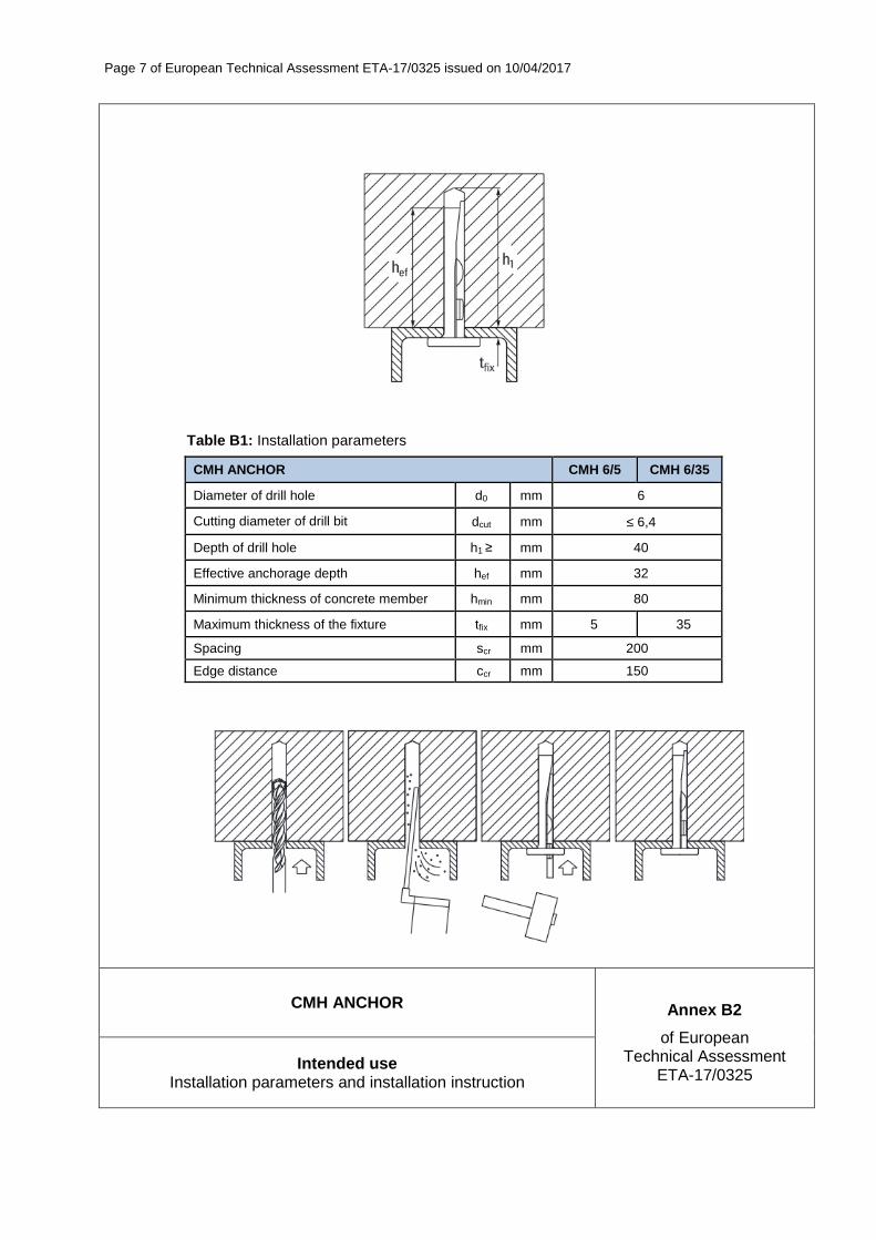
� Anchor installation such that the effective anchorage depth is complied with; the compliance is ensured if the thickness of the fixture is not larger than the maximum values given in Annex B2.
� Anchor expansion by impact on the wedge of the anchor; the anchor is properly set if the wedge is fully dropped in.
� Anchor can only be set once.
Page 7 of European Technical Assessment ETA-17/0325 issued on 10/04/2017
CMH ANCHOR Annex B2
of European Technical Assessment
ETA-17/0325 Intended use
Installation parameters and installation instruction
Table B1: Installation parameters
CMH ANCHOR CMH 6/5 CMH 6/35
Diameter of drill hole d0 mm 6
Cutting diameter of drill bit dcut mm ≤ 6,4
Depth of drill hole h1 ≥ mm 40
Effective anchorage depth hef mm 32
Minimum thickness of concrete member hmin mm 80
Maximum thickness of the fixture tfix mm 5 35
Spacing scr mm 200
Edge distance ccr mm 150

Page 8 of European Technical Assessment ETA-17/0325 issued on 10/04/2017
CMH ANCHOR Annex C1
of European Technical Assessment
ETA-17/0325 Performances
Characteristic resistance
Table C1: Characteristic resistance (design acc. to ETAG 001, Annex C, method C)
CMH ANCHOR CMH-6/5 CMH-6/35
All load directions (tension and shear)
Characteristic resistance in cracked or non-cracked concrete C20/25 to C50/60 FRk kN 4,0
Partial safety factor γ2 - 1,0
Shear load with lever arm
Characteristic bending moment M0Rk,s [Nm] 6,97
Partial safety factor γM [-] 1,25
Displacements in cracked or non-cracked concrete C20/25 to C50/60 Tension Shear
Applied loads F [kN] 1,90 1,79
Displacements δN0 [mm] 1,85 0,22
δN∞ [mm] 0,13 0,32
Page 9 of European Technical Assessment ETA-17/0325 issued on 10/04/2017
CMH ANCHOR Annex C2
of European Technical Assessment
ETA-17/0325 Performances
Characteristic resistance under fire exposure
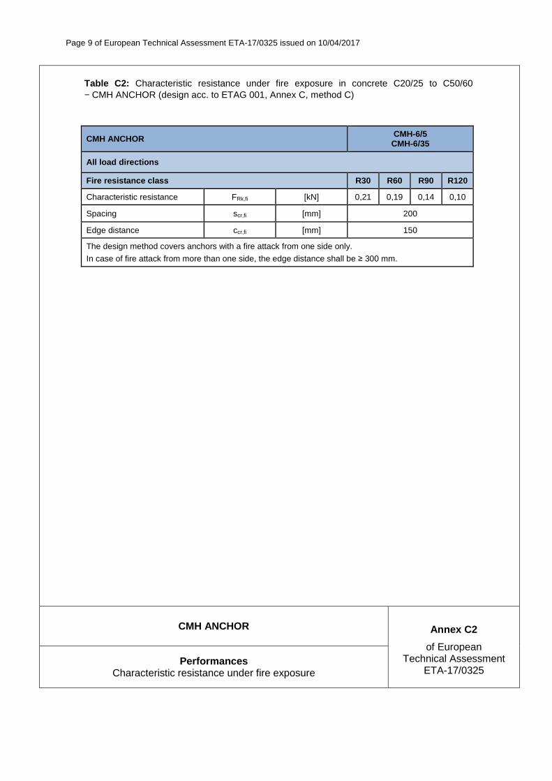
Table C2: Characteristic resistance under fire exposure in concrete C20/25 to C50/60 − CMH ANCHOR (design acc. to ETAG 001, Annex C, method C)
CMH ANCHOR CMH-6/5 CMH-6/35
All load directions
Fire resistance class R30 R60 R90 R120
Characteristic resistance FRk,fi [kN] 0,21 0,19 0,14 0,10
Spacing scr,fi [mm] 200
Edge distance ccr,fi [mm] 150
The design method covers anchors with a fire attack from one side only.
In case of fire attack from more than one side, the edge distance shall be ≥ 300 mm.

INSTYTUT TECHNIKI BUDOWLANEJ PL 00-611 WARSZAWA ul. Filtrowa 1 tel.: (+48 22) 825-04-71 (+48 22) 825-76-55 fax: (+48 22) 825-52-86 www.itb.pl
Member of
www.eota.eu
Egzemplarz archiwalny
European Technical Assessment
ETA-17/0176 of 30/03/2017
(English language translation – the original version is in Polish language)
General Part
Technical Assessment Body issuing the European Technical Assessment
Instytut Techniki Budowlanej
Trade name of the construction product RDI ANCHOR
Product family to which the construction product belongs
Deformation-controlled expansion anchors for use in non-cracked concrete
Manufacturer
Rex Fastening Systems (HK) Ltd. Unit 2005, 20/F, Enterprise Square 3 39 Wang Chiu Road Kowloon Bay, Hong Kong
Manufacturing plant Manufacturing Plant no. 3
This European Technical Assessment contains
11 pages including 3 Annexes which form an integral part of this Assessment
This European Technical Assessment is issued in accordance with Regulation (EU) No 305/2011, on the basis of
European Assessment Document (EAD) 330232-00-0601 “Mechanical fasteners for use in concrete”
®
Designated according
to Article 29 of
Regulation (EU) No 305/2011
and member of EOTA
(European Organisation for
Technical Assessment)

Page 2 of European Technical Assessment ETA-17/0176, issued on 30/03/2017
This European Technical Assessment is issued by the Technical Assessment Body in its official language. Translations of this European Technical Assessment in other languages shall fully correspond to the original issued document and should be identified as such.
Communication of this European Technical Assessment, including transmission by electronic means, shall be in full. However, partial reproduction may be made, with the written consent of the issuing Technical Assessment Body. Any partial reproduction has to be identified as such.

Page 3 of European Technical Assessment ETA-17/0176, issued on 30/03/2017
Specific Part
1 Technical description of the product
RDI ANCHOR are deformation-controlled expansion anchors. The anchors RDI ANCHOR are made of zinc plated steel.
The anchor is installed in a drilled hole and anchored by deformation-controlled expansion.
The description of the product is given in Annex A.
2 Specification of the intended use in accordance with the applicable European Assessment Document (EAD)
The performances given in Section 3 are only valid if the anchors are used in compliance with the specifications and conditions given in Annex B.
The performances given in this European Technical Assessment are based on an assumed working life of the anchor of 50 years. The indications given on the working life cannot be interpreted as a guarantee given by the producer or the Technical Assessment Body, but are to be regarded only as a means for choosing the right products in relation to the expected economically reasonable working life of the works.
3 Performance of the product and references to the methods used for its assessment
3.1 Performance of the product
3.1.1 Mechanical resistance and stability (BWR 1)
Essential characteristic Performance
Characteristic resistance, displacements See Annexes C1 to C3
Edge distance and spacing See Annexes C1 to C3
3.1.2 Safety in case of fire (BWR 2)
Essential characteristic Performance
Reaction to fire Anchors satisfy requirements for Class A1
Resistance to fire No performance assessed
3.2 Methods used for the assessment
The assessment of fitness of the anchors for the declared intended use in relation to the requirements for mechanical resistance and stability and safety in case of fire in the sense of the Basic Requirements 1 and 2 has been made in accordance with the EAD 330232-00-0601 “Mechanical fasteners for use in concrete”.

Page 4 of European Technical Assessment ETA-17/0176, issued on 30/03/2017
4 Assessment and verification of constancy of performance (AVCP) system applied, with reference to its legal base
According to Decision 96/582/EC of the European Commission the system of assessment and verification of constancy of performance (see Annex V to Regulation (EU) No 305/2011) given in the following table applies.
Product Intended use Level or class System
Metal anchors for use in concrete
For fixing and/or supporting to concrete structural elements (which contributes to the stability of the works) or heavy units
− 1
5 Technical details necessary for the implementation of the AVCP system, as provided for in the applicable European Assessment Document (EAD)
Technical details necessary for the implementation of the AVCP system are laid down in the control plan which is deposited at Instytut Techniki Budowlanej.
For type testing the results of the tests performed as part of the assessment for the European Technical Assessment shall be used unless there are changes in the production line or plant. In such cases the necessary type testing has to be agreed between Instytut Techniki Budowlanej and the notified body.
Issued in Warsaw on 30/03/2017 by Instytut Techniki Budowlanej
Marcin M. Kruk, PhD Director of ITB
Page 5 of European Technical Assessment ETA-17/0176, issued on 30/03/2017
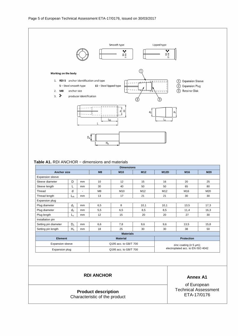
Table A1. RDI ANCHOR − dimensions and materials Dimensions
Anchor size M8 M10 M12 M12D M16 M20
Expansion sleeve
Sleeve diameter D mm 10 12 15 16 20 25
Sleeve length L mm 30 40 50 50 65 80
Thread d - M8 M10 M12 M12 M16 M20
Thread length Lth mm 13 17 21 21 30 30
Expansion plug
Plug diameter d1 mm 6,5 8 10,1 10,1 13,5 17,3
Plug diameter d2 mm 5,5 6,5 8,5 8,5 11,4 16,3
Plug length Lc mm 12 15 20 20 27 30
Installation pin
Setting pin diameter Ds mm 6,6 7,8 9,6 9,6 13,5 15,8
Setting pin length Hs mm 18 25 30 30 38 50
Materials
Element Material Protection
Expansion sleeve Q195 acc. to GB/T 700 zinc coating (≥ 5 µm); electroplated acc. to EN ISO 4042 Expansion plug Q195 acc. to GB/T 700
RDI ANCHOR Annex A1
of European Technical Assessment
ETA-17/0176 Product description
Characteristic of the product

Page 6 of European Technical Assessment ETA-17/0176, issued on 30/03/2017
RDI ANCHOR Annex B1
of European Technical Assessment
ETA-17/0176 Intended use Specification
SPECIFICATION OF INTENDED USE
Anchorages subject to:
� Static and quasi-static loads.
Base material:
� Reinforced or unreinforced normal weight concrete of strength class C20/25 at minimum to C50/60 at maximum according to EN 206.
� Non-cracked concrete.
Use conditions (environmental conditions):
� Structures subject to dry internal conditions.
Design:
� Anchorages are designed under the responsibility of an engineer experienced in anchorages and concrete work.
� Verifiable calculation notes and drawings are prepared taking account of the loads to be transmitted. The position of the anchor is indicated on the design drawings (e.g. position of the anchor relative to reinforcement or to supports, etc.).
� Anchorages under static and quasi-static loads are designed in accordance with EOTA Technical Report TR 055.
Installation:
� Anchor installation carried out by appropriately qualified personnel and under the supervision of the person responsible for technical matters of the site.
� Use of the anchor only as supplied by the manufacturer without exchanging any component of the anchor. � Anchor installation in accordance with the manufacturer's specifications and drawings and using the
appropriate tools. � Check of concrete being well compacted, e.g. without significant voids. � Positioning of the drill holes without damaging the reinforcement. � In case of aborted hole: new drilling at a minimum distance away of twice the depth of the aborted hole or
smaller distance if the aborted drill hole is filled with high strength mortar and if under shear or oblique tension load it is not in the direction of load application.
� Anchor installation such that the effective anchorage depth is complied with.

Page 7 of European Technical Assessment ETA-17/0176, issued on 30/03/2017
RDI ANCHOR Annex B2
of European Technical Assessment
ETA-17/0176 Intended use
Installation parameters
hmin
h1
hef
tfix
df
Ls
Table B1: Installation parameters
Anchor RDI ANCHOR
Size M8 M10 M12 M12D M16 M20
Effective anchorage depth hef [mm] 30 40 50 50 65 80
Drill hole depth h1 [mm] 33 43 54 54 70 85
Drill hole diameter d0 [mm] 10 12 15 16 20 25
Installation torque (max) Tinst [mm] 8 15 35 35 60 120
Thickness of concrete member (min) hmin [mm] 100 100 100 100 130 160
Screwing depth (min) Ls, min [mm] 8 10 12 12 16 20
Screwing depth (max) Ls, max [mm] 13 17 21 21 30 30
Diameter of clearance hole in the fixture
df [mm] 9 12 14 14 18 22
Spacing (min) smin [mm] 41 54 68 68 88 108
Edge distance (min) cmin [mm] 41 54 68 68 88 108
Fastening screws or anchor threaded rods:
Steel, property class 4.6 / 4.8 / 5.8 / 6.8 / 8.8 according to EN-ISO 898-1; thickness of galvanizing ≥ 5 µm

Page 8 of European Technical Assessment ETA-17/0176, issued on 30/03/2017
RDI ANCHOR Annex B3
of European Technical Assessment
ETA-17/0176 Intended use
Installation instruction and tools
Drill hole with rotary percussive machine. Drill to a required depth.
Blow out dust at least 3 times with a hand pump.
RDI S
M8
Put the anchor into the drill hole, hammering with the installation tool, until the setting pin fully insert into the anchor.
Tinst
RDI S
M8
Fix the fixture by screw or threaded rod with max. Tinst.

Page 9 of European Technical Assessment ETA-17/0176, issued on 30/03/2017
RDI ANCHOR Annex C1
of European Technical Assessment
ETA-17/0176 Performances
Characteristic resistance to tension load
Table C1: Characteristic resistance to tension load in non-cracked concrete (static and quasi-static loading)
Anchor RDI ANCHOR
Size M8 M10 M12 M12D M16 M20
Steel failure
Steel failure with threaded rod grade 4.6
Characteristic resistance NRk,s [kN] 14,6 23,2 33,7 33,7 62,8 98,0
Partial safety factor γMs 2) [-] 2,0 2,0 2,0 2,0 2,0 2,0
Steel failure with threaded rod grade 4.8
Characteristic resistance NRk,s [kN] 14,6 23,2 33,7 33,7 62,8 98,0
Partial safety factor γMs 2) [-] 1,5 1,5 1,5 1,5 1,5 1,5
Steel failure with threaded rod grade 5.8
Characteristic resistance NRk,s [kN] 18,3 29,0 42,2 42,2 78,5 122,5
Partial safety factor γMs 2) [-] 1,5 1,5 1,5 1,5 1,5 1,5
Steel failure with threaded rod grade 6.8
Characteristic resistance NRk,s [kN] 22,0 34,8 50,6 50,6 94,2 147,0
Partial safety factor γMs 2) [-] 1,5 1,5 1,5 1,5 1,5 1,5
Steel failure with threaded rod grade 8.8
Characteristic resistance NRk,s [kN] 29,3 46,4 67,4 67,4 125,6 196,0
Partial safety factor γMs 2) [-] 1,5 1,5 1,5 1,5 1,5 1,5
Pullout failure
Characteristic resistance in non-cracked concrete C20/25
NRk,p [kN] 1) 1) 1) 1) 25 30
Installation safety factor γ2 3) = γinst
4) 5) [-] 1,2 1,2 1,4 1,2 1,2 1,2
Increasing factor
concrete C30/37
ψc
[-] 1,22 1,22 1,22 1,22 1,22 1,22
concrete C40/50 [-] 1,41 1,41 1,41 1,41 1,41 1,41
concrete C50/60 [-] 1,55 1,55 1,55 1,55 1,55 1,55
Concrete cone failure and splitting failure
Effective embedment depth hef [mm] 30 40 50 50 65 80
Factor for non-cracked concrete k1 3) = kucr
4) [-] 10,1 10,1 10,1 10,1 10,1 10,1
Factor for non-cracked concrete kucr,N 5) [-] 11,0 11,0 11,0 11,0 11,0 11,0
Installation safety factor γ2 3) = γinst
4) 5) [-] 1,2 1,2 1,4 1,2 1,2 1,2
Increasing factor
concrete C30/37
ψc
[-] 1,22 1,22 1,22 1,22 1,22 1,22
concrete C40/50 [-] 1,41 1,41 1,41 1,41 1,41 1,41
concrete C50/60 [-] 1,55 1,55 1,55 1,55 1,55 1,55
Characteristic resistance to splitting N0Rk,sp [kN] 1) 1) 1) 1) 25 30
Characteristic spacing
concrete cone failure scr,N [mm] 90 120 150 150 195 240
splitting failure scr,sp [mm] 210 280 350 350 455 560
Characteristic edge distance
concrete cone failure ccr,N [mm] 45 60 75 75 97 120
splitting failure ccr,sp [mm] 105 140 175 175 227 280

Page 10 of European Technical Assessment ETA-17/0176, issued on 30/03/2017
RDI ANCHOR Annex C2
of European Technical Assessment
ETA-17/0176 Performances
Characteristic resistance to shear loads
Table C2: Characteristic resistance to shear load in non-cracked concrete (static and quasi-static loading)
Anchor RDI ANCHOR
Size M8 M10 M12 M12D M16 M20
Steel failure without lever arm
Steel failure with threaded rod grade 4.6
Characteristic resistance VRk,s 3)4) = V0
Rk,s 5)
[kN] 7,3 11,6 31,4 16,9 31,4 49,0
Factor considering ductility k 3) = k2 4) = k7
5) [-] 0,8 0,8 0,8 0,8 0,8 0,8
Partial safety factor γMs 2) [-] 1,67 1,67 1,67 1,67 1,67 1,67
Steel failure with threaded rod grade 4.8
Characteristic resistance VRk,s 3)4) = V0
Rk,s 5)
[kN] 7,3 11,6 31,4 16,9 31,4 49,0
Factor considering ductility k 3) = k2 4) = k7
5) [-] 0,8 0,8 0,8 0,8 0,8 0,8
Partial safety factor γMs 2) [-] 1,25 1,25 1,25 1,25 1,25 1,25
Steel failure with threaded rod grade 5.8
Characteristic resistance VRk,s 3)4) = V0
Rk,s 5)
[kN] 9,2 14,5 39,3 21,1 39,3 61,3
Factor considering ductility k 3) = k2 4) = k7
5) [-] 0,8 0,8 0,8 0,8 0,8 0,8
Partial safety factor γMs 2) [-] 1,25 1,25 1,25 1,25 1,25 1,25
Steel failure with threaded rod grade 6.8
Characteristic resistance VRk,s 3)4) = V0
Rk,s 5)
[kN] 11,0 17,4 47,1 25,3 47,1 73,5
Factor considering ductility k 3) = k2 4) = k7
5) [-] 0,8 0,8 0,8 0,8 0,8 0,8
Partial safety factor γMs 2) [-] 1,25 1,25 1,25 1,25 1,25 1,25
Steel failure with threaded rod grade 8.8
Characteristic resistance VRk,s 3)4) = V0
Rk,s 5)
[kN] 14,6 23,2 62,8 33,7 62,8 98,0
Factor considering ductility k 3) = k2 4) = k7
5) [-] 0,8 0,8 0,8 0,8 0,8 0,8
Partial safety factor γMs 2) [-] 1,25 1,25 1,25 1,25 1,25 1,25
Steel failure with lever arm
Steel failure with threaded rod grade 4.6
Characteristic bending resistance M0Rk,s [Nm] 15,0 29,9 52,4 52,4 133,3 259,8
Partial safety factor γMs 2) [-] 1,67 1,67 1,67 1,67 1,67 1,67
Steel failure with threaded rod grade 4.8
Characteristic bending resistance M0Rk,s [Nm] 15,0 29,9 52,4 52,4 133,3 259,8
Partial safety factor γMs 2) [-] 1,25 1,25 1,25 1,25 1,25 1,25
Steel failure with threaded rod grade 5.8
Characteristic bending resistance M0Rk,s [Nm] 18,8 37,4 65,6 65,6 166,6 324,8
Partial safety factor γMs 2) [-] 1,25 1,25 1,25 1,25 1,25 1,25
Steel failure with threaded rod grade 6.8
Characteristic bending resistance M0Rk,s [Nm] 22,5 44,9 78,7 78,7 199,9 389,7
Partial safety factor γMs 2) [-] 1,25 1,25 1,25 1,25 1,25 1,25
Steel failure with threaded rod grade 8.8
Characteristic bending resistance M0Rk,s [Nm] 30,0 59,9 104,9 104,9 266,6 519,7
Partial safety factor γMs 2) [-] 1,25 1,25 1,25 1,25 1,25 1,25

Page 11 of European Technical Assessment ETA-17/0176, issued on 30/03/2017
RDI ANCHOR Annex C3
of European Technical Assessment
ETA-17/0176 Performances
Characteristic resistance and displacements
Table C3: Characteristic resistance and displacements (static and quasi-static loading)
Anchor RDI ANCHOR
Size M8 M10 M12 M12D M16 M20
Resistance to pry-out failure
Factor for non-cracked concrete k 3) = k3 4) = k8
5) [-] 1,0 1,0 1,0 1,0 2,0 2,0
Partial safety factor γMs 2) [-] 1,5 1,5 1,5 1,5 1,5 1,5
Resistance to concrete edge failure
Outside diameter of anchor dnom [mm] 10 12 15 16 20 25
Effective length of anchor under shear loads
lf [mm] 30 40 50 50 65 80
Partial safety factor γMc 2) [-] 1,5 1,5 1,5 1,5 1,5 1,5
Minimum member thickness hmin [mm] 100 100 100 100 130 160
Minimum edge distance cmin [mm] 41 54 68 68 88 108
Minimum spacing smin [mm] 41 54 68 68 88 108
Displacements under static and quasi-static loading
Tension and shear load in non-cracked concrete C20/25 to C50/60
Tension load and shear load N = V [kN] 4,44 6,91 6,40 9,92 11,46 23,86
Short term tension displacement δN0 [mm] 0,98 3,54 3,06 2,73 1,15 4,26
Long term tension displacement δN∞ [mm] 0,50 0,50 0,38 0,50 0,50 0,50
Short term shear displacement δV0 [mm] 0,98 3,54 3,06 2,73 1,15 4,26
Long term shear displacement δV∞ [mm] 0,50 0,50 0,38 0,50 0,50 0,50
1) Pull-out failure mode is not decisive 2) 3) Parameter for design acc. to ETAG 001 Annex C 4) Parameter for design acc. to CEN/TS 1992-4-4:2009 5) Parameter for design acc. to prEN 1992-4:2016

INSTYTUT TECHNIKI BUDOWLANEJ PL 00-611 WARSZAWA ul. Filtrowa 1 tel.: (+48 22) 825-04-71 (+48 22) 825-76-55 fax: (+48 22) 825-52-86 www.itb.pl
Member of
www.eota.eu
European Technical Assessment
ETA-17/0177 of 30/03/2017
(English language translation – the original version is in Polish language)
General Part
Technical Assessment Body issuing the European Technical Assessment
Instytut Techniki Budowlanej
Trade name of the construction product RDI ANCHOR
Product family to which the construction product belongs
Deformation-controlled expansion anchors for multiple use for non-structural applications in concrete
Manufacturer
Rex Fastening Systems (HK) Ltd. Unit 2005, 20/F, Enterprise Square 3 39 Wang Chiu Road Kowloon Bay, Hong Kong
Manufacturing plant(s) Manufacturing Plant no. 3
This European Technical Assessment contains
10 pages including 3 Annexes which form an integral part of this assessment
This European Technical Assessment is issued in accordance with Regulation (EU) No 305/2011, on the basis of
Guideline for European Technical Approval ETAG 001, Edition April 2013 “Metal anchors for use in concrete – Part 1: Anchors in general and Part 6: Anchors for multiple use for non-structural applications”, used as European Assessment Document (EAD)
®
Designated according
to Article 29 of
Regulation (EU) No 305/2011
and member of EOTA
(European Organisation for
Technical Assessment)
Page 2 of European Technical Assessment ETA-17/0177, issued on 30/03/2017
This European Technical Assessment is issued by the Technical Assessment Body in its official language. Translations of this European Technical Assessment in other languages shall fully correspond to the original issued document and should be identified as such.
Communication of this European Technical Assessment, including transmission by electronic means, shall be in full. However, partial reproduction may be made, with the written consent of the issuing Technical Assessment Body. Any partial reproduction has to be identified as such.

Page 3 of European Technical Assessment ETA-17/0177, issued on 30/03/2017
Specific Part
1 Technical description of the product
The RDI ANCHOR are deformation-controlled expansion anchors. The anchors are made of zinc plated steel.
The anchor is installed in a drilled hole and anchored by deformation-controlled expansion.
The description of the product is given in Annex A.
2 Specification of the intended use in accordance with the applicable European Assessment Document (EAD)
The performances given in Section 3 are only valid if the anchors are used in compliance with the specifications and conditions given in Annex B.
The performances given in this European Technical Assessment are based on an assumed working life of the anchor of 50 years. The indications given on the working life cannot be interpreted as a guarantee given by the producer or the Technical Assessment Body, but are to be regarded only as a means for choosing the right products in relation to the expected economically reasonable working life of the works.
3 Performance of the product and references to the methods used for its assessment
3.1 Performance of the product
3.1.1 Mechanical resistance and stability (BWR 1)
Essential characteristic Performance
Characteristic resistance for all load directions See Annex C1
Edge distances and spacing See Annex C1
3.1.2 Safety in case of fire (BWR 2)
Essential characteristic Performance
Reaction to fire Anchors satisfy requirements for Class A1
Resistance to fire See Annex C2
3.1.3 Hygiene, health and the environment (BWR 3)
Regarding the dangerous substances clauses contained in this European Technical Assessment, there may be requirements applicable to the products falling within its scope (e.g. transposed European legislation and national laws, regulations and administrative provisions). In order to meet the provisions of the Construction Products Regulation, these requirements need also to be complied with, when and where they apply.
Page 4 of European Technical Assessment ETA-17/0177, issued on 30/03/2017
3.1.4 Safety and accessibility in use (BWR 4)
For Basic Requirement Safety in use the same criteria are valid as for Basic Requirement Mechanical resistance and stability (BWR 1).
3.1.5 Sustainable use of natural resources (BWR 7)
No performance assessed.
3.1.6 General aspects relating to fitness for use
Durability and serviceability are only ensured if the specifications of intended use according to Annex B1 are kept.
3.2 Methods used for the assessment
The assessment of fitness of the anchors for the declared intended use in relation to the requirements for mechanical resistance and stability and safety in use in the sense of the Basic Requirements 1 and 4 has been made in accordance with the ETAG 001 “Metal anchors for use in concrete”, Part 1: “Anchors in general” and Part 6: “Anchors for multiple use for non-structural applications”. The assessment of the anchor for the intended use in relation to the requirements for resistance to fire has been made in accordance with the EOTA Technical Report TR 020 “Evaluation of anchorages in concrete concerning resistance to fire”.
4 Assessment and verification of constancy of performance (AVCP) system applied, with reference to its legal base
According to Decision 97/161/EC of the European Commission the system of assessment and verification of constancy of performance (see Annex V to Regulation (EU) No 305/2011) given in the following table applies.
Product Intended use Level or class System
Metal anchors for use in concrete (light-duty type)
For use in redundant systems for fixing and/or supporting to concrete elements such as lightweight suspended ceilings, as well as installations
− 2+
5 Technical details necessary for the implementation of the AVCP system, as provided for in the applicable European Assessment Document (EAD)
Technical details necessary for the implementation of the AVCP system are laid down in the control plan which is deposited at Instytut Techniki Budowlanej.
For type testing the results of the tests performed as part of the assessment for the European Technical Assessment shall be used unless there are changes in the production line or plant. In such cases the necessary type testing has to be agreed between Instytut Techniki Budowlanej and the notified body.
Issued in Warsaw on 30/03/2017 by Instytut Techniki Budowlanej
Marcin M. Kruk, PhD Director of ITB
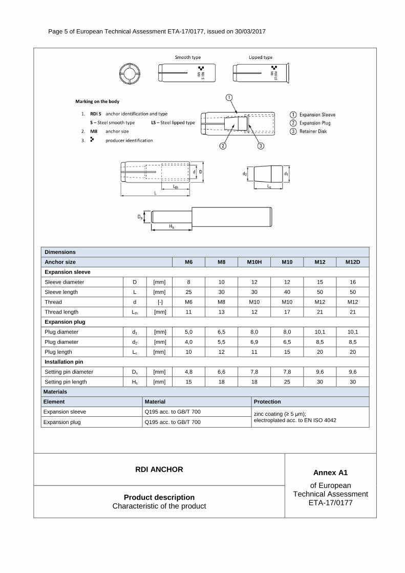
Page 5 of European Technical Assessment ETA-17/0177, issued on 30/03/2017
Dimensions
Anchor size M6 M8 M10H M10 M12 M12D
Expansion sleeve
Sleeve diameter D [mm] 8 10 12 12 15 16
Sleeve length L [mm] 25 30 30 40 50 50
Thread d [-] M6 M8 M10 M10 M12 M12
Thread length Lth [mm] 11 13 12 17 21 21
Expansion plug
Plug diameter d1 [mm] 5,0 6,5 8,0 8,0 10,1 10,1
Plug diameter d2 [mm] 4,0 5,5 6,9 6,5 8,5 8,5
Plug length Lc [mm] 10 12 11 15 20 20
Installation pin
Setting pin diameter Ds [mm] 4,8 6,6 7,8 7,8 9,6 9,6
Setting pin length Hs [mm] 15 18 18 25 30 30
Materials
Element Material Protection
Expansion sleeve Q195 acc. to GB/T 700 zinc coating (≥ 5 µm); electroplated acc. to EN ISO 4042 Expansion plug Q195 acc. to GB/T 700
RDI ANCHOR Annex A1
of European Technical Assessment
ETA-17/0177 Product description
Characteristic of the product

Page 6 of European Technical Assessment ETA-17/0177, issued on 30/03/2017
RDI ANCHOR Annex B1
of European Technical Assessment
ETA-17/0177 Intended use Specification
SPECIFICATION OF INTENDED USE
Anchorages subject to:
� Multiple use for non-structural applications. The definition of multiple use according to the Member States is given on the informative Annex 1 of ETAG 001, Part 6.
� Static and quasi-static loads. � Anchorages with requirements related to resistance to fire.
Base material:
� Reinforced or unreinforced normal weight concrete of strength class C20/25 at minimum to C50/60 at maximum according to EN 206.
� Non-cracked and cracked concrete.
Use conditions (environmental conditions):
� Structures subject to dry internal conditions.
Design:
� Anchorages are designed under the responsibility of an engineer experienced in anchorages and concrete work.
� Verifiable calculation notes and drawings are prepared taking account of the loads to be transmitted. The position of the anchor is indicated on the design drawings (e.g. position of the anchor relative to reinforcement or to supports, etc.).
� Anchorages under static and quasi-static loads are designed in accordance with ETAG 001, Annex C, design method B, Edition August 2010.
� The design of anchorages under fire exposure has to consider the conditions given in the EOTA Technical Report TR 020.
Installation:
� Anchor installation carried out by appropriately qualified personnel and under the supervision of the person responsible for technical matters of the site.
� Use of the anchor only as supplied by the manufacturer without exchanging any component of the anchor. � Anchor installation in accordance with the manufacturer's specifications and drawings and using the
appropriate tools. � Check of concrete being well compacted, e.g. without significant voids. � Positioning of the drill holes without damaging the reinforcement. � In case of aborted hole: new drilling at a minimum distance away of twice the depth of the aborted hole or
smaller distance if the aborted drill hole is filled with high strength mortar and if under shear or oblique tension load it is not in the direction of load application.
� Anchor installation such that the effective anchorage depth is complied with.

Page 7 of European Technical Assessment ETA-17/0177, issued on 30/03/2017
RDI ANCHOR Annex B2
of European Technical Assessment
ETA-17/0177 Intended use
Installation parameters
hmin
h1
hef
tfix
df
Ls
Table B1: Installation parameters
Anchor RDI ANCHOR
Size M6 M8 M10H M10 M12 M12D
Effective anchorage depth hef [mm] 25 30 30 40 50 50
Drill hole depth h1 [mm] 28 33 33 43 54 54
Drill hole diameter d0 [mm] 8 10 12 12 15 16
Installation torque (max) Tinst [mm] 4 8 15 15 35 35
Thickness of concrete member (min)
hmin [mm] 80 80 80 80 100 100
Screwing depth (min) Ls, min [mm] 6 8 8 10 12 12
Screwing depth (max) Ls, max [mm] 11 13 12 17 21 21
Diameter of clearance hole in the fixture df [mm] 7 9 12 12 14 14
Spacing (min) smin [mm] 200 200 200 200 200 200
Edge distance (min) cmin [mm] 150 150 150 150 150 150
Fastening screws or anchor threaded rods:
Steel, property class 4.6 / 4.8 / 5.8 / 6.8 / 8.8 according to EN-ISO 898-1; thickness of galvanizing ≥ 5 µm
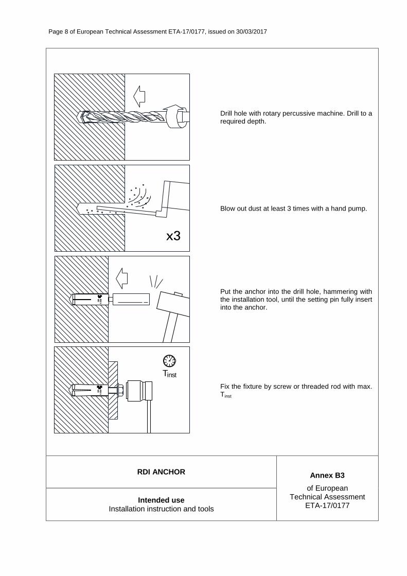
Page 8 of European Technical Assessment ETA-17/0177, issued on 30/03/2017
RDI ANCHOR Annex B3
of European Technical Assessment
ETA-17/0177 Intended use
Installation instruction and tools
Drill hole with rotary percussive machine. Drill to a required depth.
Blow out dust at least 3 times with a hand pump.
RDI S
M8
Put the anchor into the drill hole, hammering with the installation tool, until the setting pin fully insert into the anchor.
Tinst
RDI S
M8
Fix the fixture by screw or threaded rod with max. Tinst

Page 9 of European Technical Assessment ETA-17/0177, issued on 30/03/2017
RDI ANCHOR Annex C1
of European Technical Assessment
ETA-17/0177 Performances
Characteristic resistance
Table C1: Characteristic resistance in concrete C20/25 to C50/60 (design acc. to ETAG 001, Annex C, method B)
Anchor RDI ANCHOR
Size M6 M8 M10H M10 M12 M12D
All load directions (fastening screw or threaded rod property class ≥ 4.6)
Characteristic resistance in concrete
C20/25 to C50/60 FRk [kN] 1,5 2,0 3,0 3,0 4,0 5,0
Partial (installation) safety factor γ2 [-] 1,4 1,4 1,4 1,4 1,4 1,4
Spacing scr [mm] 200 200 200 200 200 200
Edge distance ccr [mm] 150 150 150 150 150 150
Minimum member thickness hmin [mm] 80 80 80 80 100 100
Shear load: steel failure with lever arm
Characteristic bending moment: screw class 4.6 M0Rk,S [Nm] 6,1 15,0 29,9 29,9 52,4 52,4
Characteristic bending moment: screw class 4.8 M0Rk,S [Nm] 6,1 15,0 29,9 29,9 52,4 52,4
Characteristic bending moment: screw class 5.8 M0Rk,S [Nm] 7,6 18,8 37,4 37,4 65,6 65,6
Characteristic bending moment: screw class 6.8 M0Rk,S [Nm] 9,2 22,5 44,9 44,9 78,7 78,7
Characteristic bending moment: screw class 8.8 M0Rk,S [Nm] 12,2 30,0 59,9 59,9 104,9 104,9
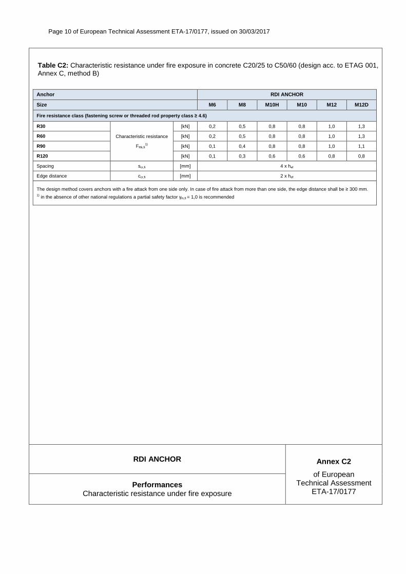
Page 10 of European Technical Assessment ETA-17/0177, issued on 30/03/2017
RDI ANCHOR Annex C2
of European Technical Assessment
ETA-17/0177 Performances
Characteristic resistance under fire exposure
Table C2: Characteristic resistance under fire exposure in concrete C20/25 to C50/60 (design acc. to ETAG 001, Annex C, method B)
Anchor RDI ANCHOR
Size M6 M8 M10H M10 M12 M12D
Fire resistance class (fastening screw or threaded rod property class ≥ 4.6)
R30
Characteristic resistance
FRk,fi1)
[kN] 0,2 0,5 0,8 0,8 1,0 1,3
R60 [kN] 0,2 0,5 0,8 0,8 1,0 1,3
R90 [kN] 0,1 0,4 0,8 0,8 1,0 1,1
R120 [kN] 0,1 0,3 0,6 0,6 0,8 0,8
Spacing scr,fi [mm] 4 x hef
Edge distance ccr,fi [mm] 2 x hef
The design method covers anchors with a fire attack from one side only. In case of fire attack from more than one side, the edge distance shall be ≥ 300 mm. 1) in the absence of other national regulations a partial safety factor γm,fi = 1,0 is recommended