ปฏิบัติการที่ 11 · Web viewร ปท 3 Block Diagram แสดงความแตกต างระหว าง FFT และ STFT กราฟ Output
Embedded Panel Controller
- EPC10 -
User Manual
EPC10 Hardware Manual - Copyright
KURZ Industrie-Elektronik GmbH - 1 -
Copyright
Kurz Industrie-Elektronik GmbH
Föhrenbachstrasse 3
73630 Remshalden
Germany
Tel.: +49 7151 7097 0
Fax: +49 7151 7097 50
Email: [email protected]
Web: www.kurz-elektronik.de
Copyright © 2013 Kurz Industrie-Elektronik GmbH
This Hardware Manual may not be copied, reproduced, translated, changed or distributed,
completely or partially in electronic, machine readable, or in any other form without the
written consent from Kurz Industrie-Elektronik GmbH.
This document is provided for use with the EPC series, a product of Kurz Industrie Elektronik
GmbH. We provide this document without warranty of any kind - either expressed or implied -
including, but not limited to, its particular purpose. No license to our property rights is
granted. We assume no liability, provide no warranty - either expressed or implied - relating to
the usage, or intellectual property infringement that may result from its use. We may make
changes to this document without notice. Subject to misprints, errors and technical changes.
Trademarks and registered Trademarks are the property of their respective owner.
EPC10 Hardware Manual - Table of Content
KURZ Industrie-Elektronik GmbH - 2 -
Table of Content
Copyright ............................................................................................................. 1
Table of Content .................................................................................................... 2
List of Tables ..................................................................................................... 4
List of Figures .................................................................................................... 4
Revision History .................................................................................................... 5
Module Concept ..................................................................................................... 6
Example of use .................................................................................................. 6
Module Block Diagram ............................................................................................ 7
Overview .............................................................................................................. 8
Top .................................................................................................................. 8
Bottom ............................................................................................................. 8
Component Placement ........................................................................................... 9
Top View ........................................................................................................... 9
Power Supply ....................................................................................................... 10
Technical Drawings ............................................................................................... 11
Outline and drill dimensions ............................................................................... 11
Top part dimensions .......................................................................................... 11
Bottom part dimensions ..................................................................................... 12
Connector polarities........................................................................................... 12
Sample front cover plate .................................................................................... 13
Sample front cover plate with circuit board and 2 x Usb Host .................................. 13
Product Key – Ordering Information ........................................................................ 14
Function Description: CPU ..................................................................................... 15
AT91SAM9G45 - ARM9 SoC ................................................................................ 15
System Controller ............................................................................................. 16
System Controller – Allocation tables ................................................................... 17
Function Description: Interfaces ............................................................................. 18
Connector properties ......................................................................................... 18
Supply Voltage ................................................................................................. 18
RS232 ............................................................................................................. 18
RS485 ............................................................................................................. 19
Ethernet .......................................................................................................... 19
SD-Card ........................................................................................................... 19
USB-Host ......................................................................................................... 19
USB-Devise ...................................................................................................... 20
Reset/Wakeup .................................................................................................. 20
Touch .............................................................................................................. 20
TFT-Digital Allocation ......................................................................................... 21
TFT-LVDS ......................................................................................................... 22
Extension Connector Allocation ........................................................................... 23
EPC10 Hardware Manual - Table of Content
KURZ Industrie-Elektronik GmbH - 3 -
CR2032 Battery ................................................................................................ 24
JTAG ............................................................................................................... 24
Function Description: Memory ................................................................................ 25
Memory Map..................................................................................................... 25
NAND .............................................................................................................. 25
SDRAM ............................................................................................................ 25
DataFlash ......................................................................................................... 25
List of References ............................................... Fehler! Textmarke nicht definiert.
EPC10 Hardware Manual - Table of Content
KURZ Industrie-Elektronik GmbH - 4 -
List of Tables Table 1: Revision History ................................................................................................ 5
Table 2: Part List ........................................................................................................... 9
Table 3: Caption ............................................................................................................ 9
Table 4: X1001 - allocation table ................................................................................... 17
Table 5: PIC16F1828 - allocation table ........................................................................... 17
Table 6: Connector properties ....................................................................................... 18
Table 7: supply voltage ................................................................................................ 18
Table 8: RS232 ........................................................................................................... 18
Table 9: RS485 ........................................................................................................... 19
Table 10: SD-Card ....................................................................................................... 19
Table 11: Reset/Wakeup .............................................................................................. 20
Table 12: Touch .......................................................................................................... 20
Table 13: TFT-Digital Allocation ..................................................................................... 21
Table 14: TFT-LVDS .................................................................................................... 22
Table 15: Extension Connector Allocation ....................................................................... 23
List of Figures Figure 1: example of use ................................................................................................ 6
Figure 2: Module Block Diagram ...................................................................................... 7
Figure 3: Overview - Top ................................................................................................ 8
Figure 4: Overview - Bottom ........................................................................................... 8
Figure 5: Component Placement - Top View ...................................................................... 9
Figure 6: outline and drill dimensions ............................................................................. 11
Figure 7: top part dimensions ....................................................................................... 11
Figure 8: bottom part dimensions .................................................................................. 12
Figure 9: connector polarities ........................................................................................ 12
Figure 10: sample front cover plate ............................................................................... 13
Figure 11: Sample front cover plate with circuit board and 2 x Usb Host............................. 13
Figure 12: AT91SAM9G45 - Block diagram ...................................................................... 15
Figure 13: System Controller ........................................................................................ 16
Figure 14: USB-Host .................................................................................................... 19
Figure 15: USB-Device ................................................................................................. 20
Figure 16: Signal constellation of 6 bit LVDS ................................................................... 22
Figure 17: Signal constellation of 8 bit LVDS. (Each color with additional bits 6 and 7.) ....... 22
EPC10 Hardware Manual - Revision History
KURZ Industrie-Elektronik GmbH - 5 -
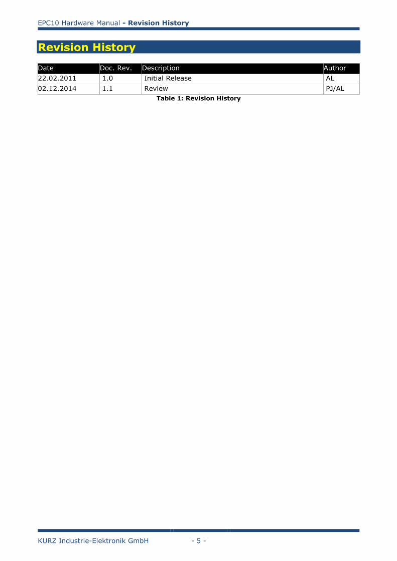
Revision History
Date Doc. Rev. Description Author
22.02.2011 1.0 Initial Release AL
02.12.2014 1.1 Review PJ/AL
Table 1: Revision History
EPC10 Hardware Manual - Module Concept
KURZ Industrie-Elektronik GmbH - 6 -
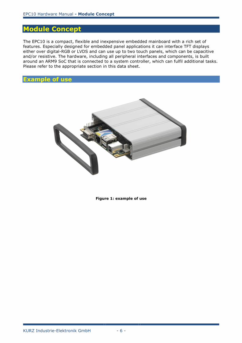
Module Concept
The EPC10 is a compact, flexible and inexpensive embedded mainboard with a rich set of
features. Especially designed for embedded panel applications it can interface TFT displays
either over digital-RGB or LVDS and can use up to two touch panels, which can be capacitive
and/or resistive. The hardware, including all peripheral interfaces and components, is built
around an ARM9 SoC that is connected to a system controller, which can fulfil additional tasks.
Please refer to the appropriate section in this data sheet.
Example of use
Figure 1: example of use
EPC10 Hardware Manual - Module Block Diagram
KURZ Industrie-Elektronik GmbH - 7 -
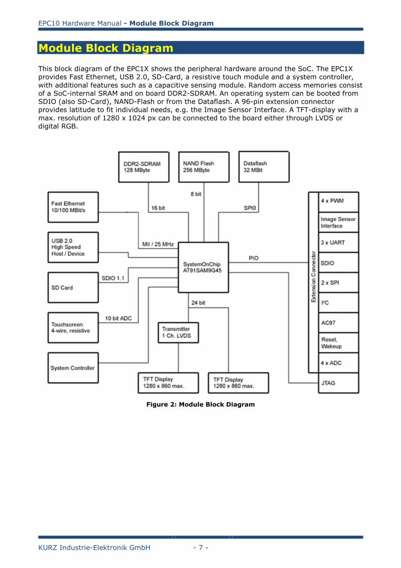
Module Block Diagram
This block diagram of the EPC1X shows the peripheral hardware around the SoC. The EPC1X
provides Fast Ethernet, USB 2.0, SD-Card, a resistive touch module and a system controller,
with additional features such as a capacitive sensing module. Random access memories consist
of a SoC-internal SRAM and on board DDR2-SDRAM. An operating system can be booted from
SDIO (also SD-Card), NAND-Flash or from the Dataflash. A 96-pin extension connector
provides latitude to fit individual needs, e.g. the Image Sensor Interface. A TFT-display with a
max. resolution of 1280 x 1024 px can be connected to the board either through LVDS or
digital RGB.
Figure 2: Module Block Diagram
EPC10 Hardware Manual - Overview
KURZ Industrie-Elektronik GmbH - 8 -
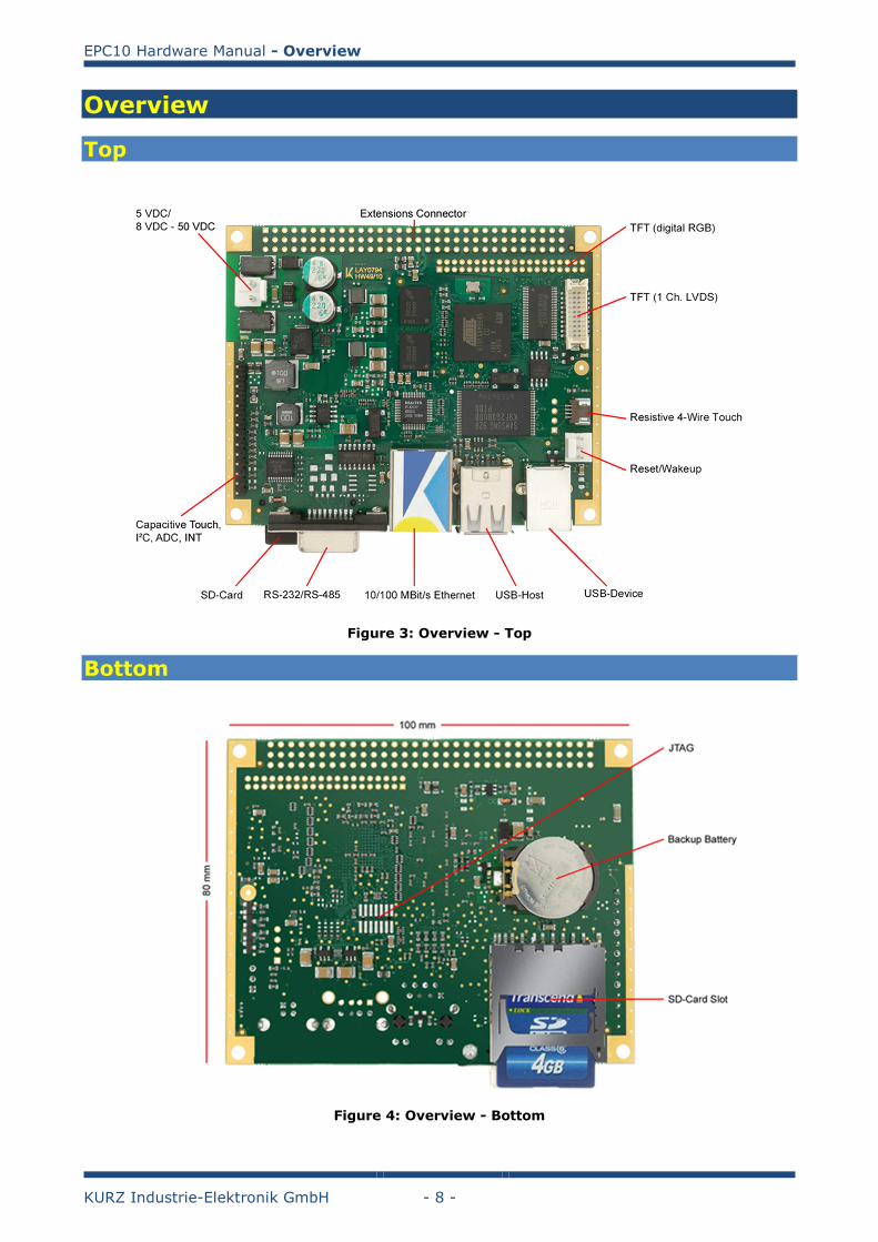
Overview
Top
Figure 3: Overview - Top
Bottom
Figure 4: Overview - Bottom
EPC10 Hardware Manual - Component Placement
KURZ Industrie-Elektronik GmbH - 9 -
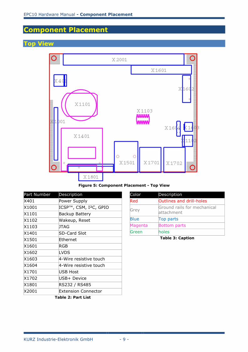
Component Placement
Top View
Figure 5: Component Placement - Top View
Part Number Description
X401 Power Supply
X1001 ICSP™, CSM, I²C, GPIO
X1101 Backup Battery
X1102 Wakeup, Reset
X1103 JTAG
X1401 SD-Card Slot
X1501 Ethernet
X1601 RGB
X1602 LVDS
X1603 4-Wire resistive touch
X1604 4-Wire resistive touch
X1701 USB Host
X1702 USB+ Device
X1801 RS232 / RS485
X2001 Extension Connector
Table 2: Part List
Color Description
Red Outlines and drill-holes
Grey Ground rails for mechanical
attachment
Blue Top parts
Magenta Bottom parts
Green holes
Table 3: Caption
EPC10 Hardware Manual - Power Supply
KURZ Industrie-Elektronik GmbH - 10 -
Power Supply
EPC10 Hardware Manual - Technical Drawings
KURZ Industrie-Elektronik GmbH - 11 -
Technical Drawings
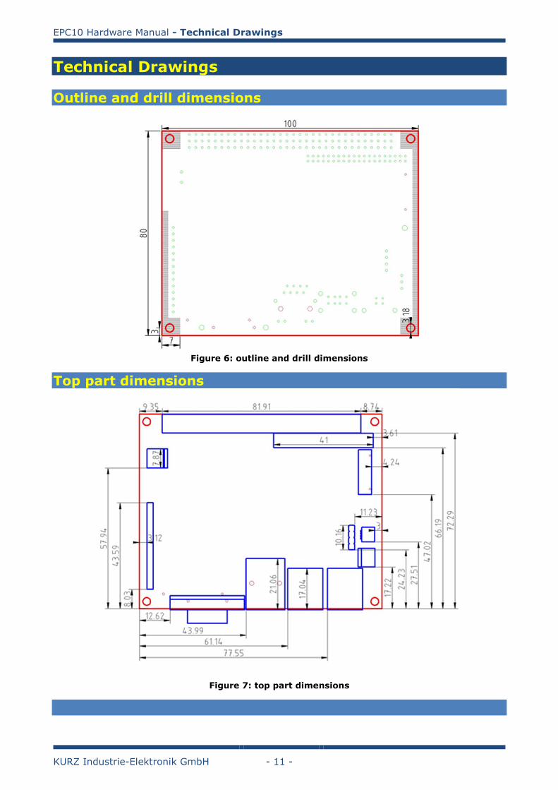
Outline and drill dimensions
Figure 6: outline and drill dimensions
Top part dimensions
Figure 7: top part dimensions
EPC10 Hardware Manual - Technical Drawings
KURZ Industrie-Elektronik GmbH - 12 -
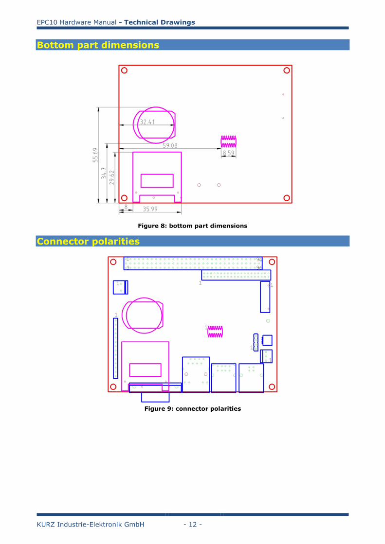
Bottom part dimensions
Figure 8: bottom part dimensions
Connector polarities
Figure 9: connector polarities
EPC10 Hardware Manual - Technical Drawings
KURZ Industrie-Elektronik GmbH - 13 -
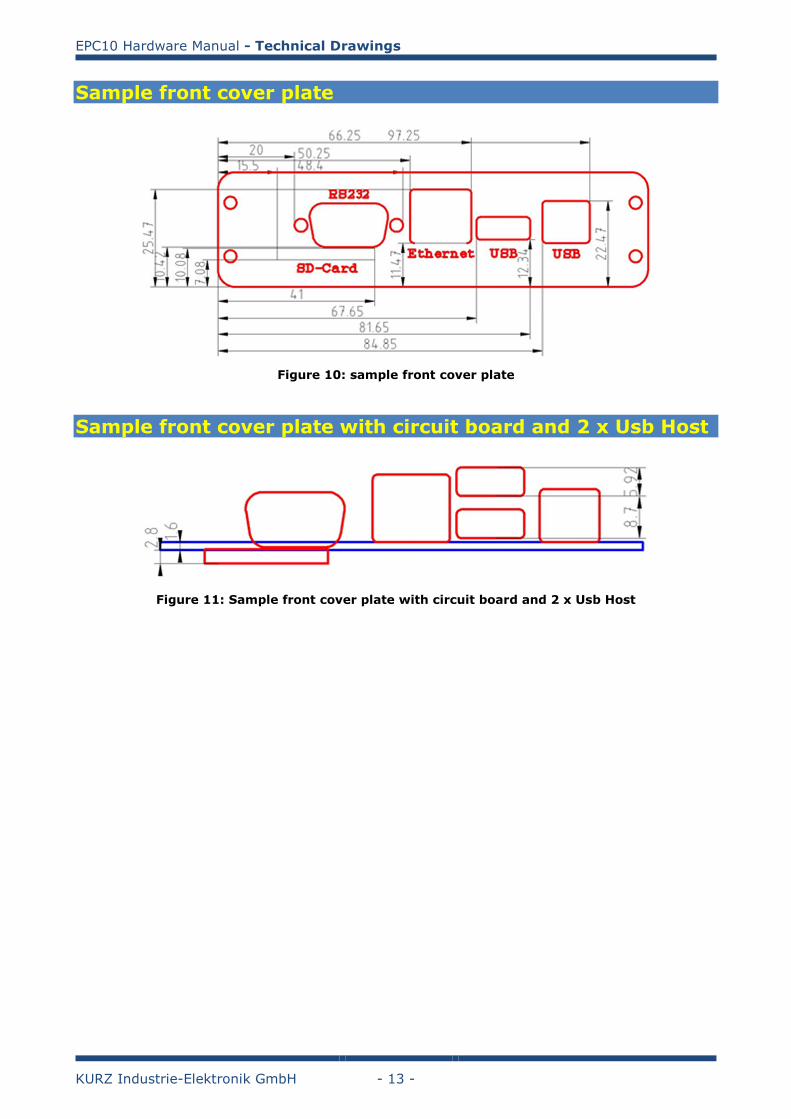
Sample front cover plate
Figure 10: sample front cover plate
Sample front cover plate with circuit board and 2 x Usb Host
Figure 11: Sample front cover plate with circuit board and 2 x Usb Host
EPC10 Hardware Manual - Product Key – Ordering Information
KURZ Industrie-Elektronik GmbH - 14 -
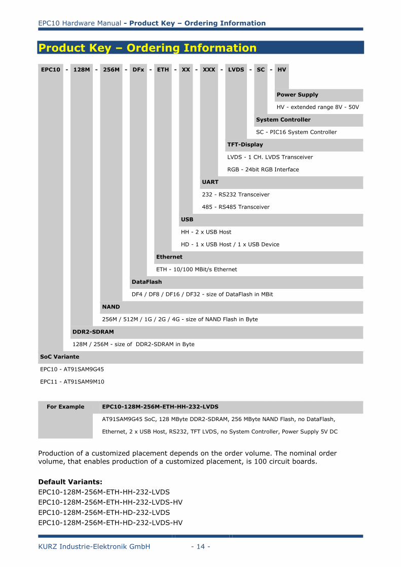
Product Key – Ordering Information
EPC10 - 128M - 256M - DFx - ETH - XX - XXX - LVDS - SC - HV
Power Supply
HV - extended range 8V - 50V
System Controller
SC - PIC16 System Controller
TFT-Display
LVDS - 1 CH. LVDS Transceiver
RGB - 24bit RGB Interface
UART
232 - RS232 Transceiver
485 - RS485 Transceiver
USB
HH - 2 x USB Host
HD - 1 x USB Host / 1 x USB Device
Ethernet
ETH - 10/100 MBit/s Ethernet
DataFlash
DF4 / DF8 / DF16 / DF32 - size of DataFlash in MBit
NAND
256M / 512M / 1G / 2G / 4G - size of NAND Flash in Byte
DDR2-SDRAM
128M / 256M - size of DDR2-SDRAM in Byte
SoC Variante
EPC10 - AT91SAM9G45
EPC11 - AT91SAM9M10
For Example EPC10-128M-256M-ETH-HH-232-LVDS
AT91SAM9G45 SoC, 128 MByte DDR2-SDRAM, 256 MByte NAND Flash, no DataFlash,
Ethernet, 2 x USB Host, RS232, TFT LVDS, no System Controller, Power Supply 5V DC
Production of a customized placement depends on the order volume. The nominal order
volume, that enables production of a customized placement, is 100 circuit boards.
Default Variants:
EPC10-128M-256M-ETH-HH-232-LVDS
EPC10-128M-256M-ETH-HH-232-LVDS-HV
EPC10-128M-256M-ETH-HD-232-LVDS
EPC10-128M-256M-ETH-HD-232-LVDS-HV
EPC10 Hardware Manual - Function Description: CPU
KURZ Industrie-Elektronik GmbH - 15 -
Function Description: CPU
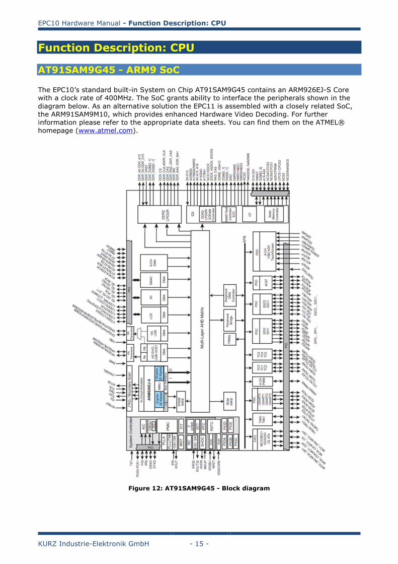
AT91SAM9G45 - ARM9 SoC
The EPC10’s standard built-in System on Chip AT91SAM9G45 contains an ARM926EJ-S Core
with a clock rate of 400MHz. The SoC grants ability to interface the peripherals shown in the
diagram below. As an alternative solution the EPC11 is assembled with a closely related SoC,
the ARM91SAM9M10, which provides enhanced Hardware Video Decoding. For further
information please refer to the appropriate data sheets. You can find them on the ATMEL®
homepage (www.atmel.com).
Figure 12: AT91SAM9G45 - Block diagram
EPC10 Hardware Manual - Function Description: CPU
KURZ Industrie-Elektronik GmbH - 16 -
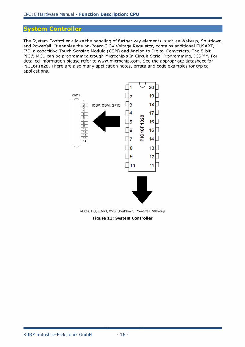
System Controller
The System Controller allows the handling of further key elements, such as Wakeup, Shutdown
and Powerfail. It enables the on-Board 3,3V Voltage Regulator, contains additional EUSART,
I²C, a capacitive Touch Sensing Module (CSM) and Analog to Digital Converters. The 8-bit
PIC® MCU can be programmed trough Microchip's In Circuit Serial Programming, ICSP™. For
detailed information please refer to www.microchip.com. See the appropriate datasheet for
PIC16F1828. There are also many application notes, errata and code examples for typical
applications.
Figure 13: System Controller
EPC10 Hardware Manual - Function Description: CPU
KURZ Industrie-Elektronik GmbH - 17 -
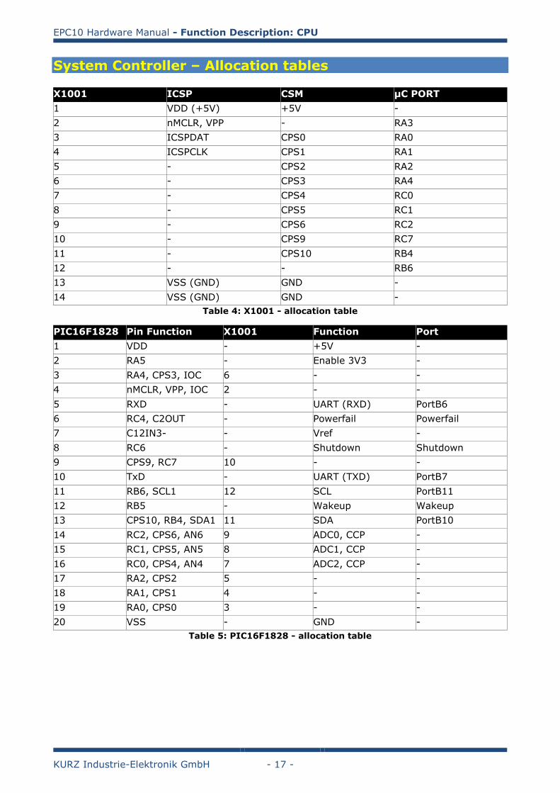
System Controller – Allocation tables
X1001 ICSP CSM µC PORT
1 VDD (+5V) +5V -
2 nMCLR, VPP - RA3
3 ICSPDAT CPS0 RA0
4 ICSPCLK CPS1 RA1
5 - CPS2 RA2
6 - CPS3 RA4
7 - CPS4 RC0
8 - CPS5 RC1
9 - CPS6 RC2
10 - CPS9 RC7
11 - CPS10 RB4
12 - - RB6
13 VSS (GND) GND -
14 VSS (GND) GND -
Table 4: X1001 - allocation table
PIC16F1828 Pin Function X1001 Function Port
1 VDD - +5V -
2 RA5 - Enable 3V3 -
3 RA4, CPS3, IOC 6 - -
4 nMCLR, VPP, IOC 2 - -
5 RXD - UART (RXD) PortB6
6 RC4, C2OUT - Powerfail Powerfail
7 C12IN3- - Vref -
8 RC6 - Shutdown Shutdown
9 CPS9, RC7 10 - -
10 TxD - UART (TXD) PortB7
11 RB6, SCL1 12 SCL PortB11
12 RB5 - Wakeup Wakeup
13 CPS10, RB4, SDA1 11 SDA PortB10
14 RC2, CPS6, AN6 9 ADC0, CCP -
15 RC1, CPS5, AN5 8 ADC1, CCP -
16 RC0, CPS4, AN4 7 ADC2, CCP -
17 RA2, CPS2 5 - -
18 RA1, CPS1 4 - -
19 RA0, CPS0 3 - -
20 VSS - GND -
Table 5: PIC16F1828 - allocation table
EPC10 Hardware Manual - Function Description: Interfaces
KURZ Industrie-Elektronik GmbH - 18 -
Function Description: Interfaces
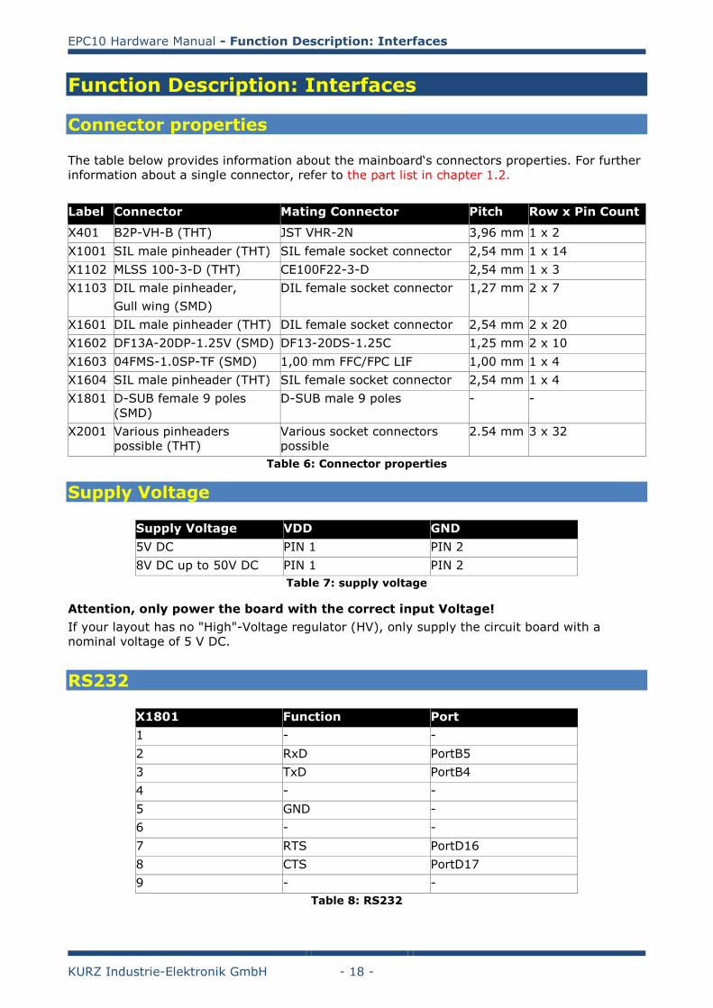
Connector properties
The table below provides information about the mainboard‘s connectors properties. For further
information about a single connector, refer to the part list in chapter 1.2.
Label Connector Mating Connector Pitch Row x Pin Count
X401 B2P-VH-B (THT) JST VHR-2N 3,96 mm 1 x 2
X1001 SIL male pinheader (THT) SIL female socket connector 2,54 mm 1 x 14
X1102 MLSS 100-3-D (THT) CE100F22-3-D 2,54 mm 1 x 3
X1103 DIL male pinheader,
Gull wing (SMD)
DIL female socket connector 1,27 mm 2 x 7
X1601 DIL male pinheader (THT) DIL female socket connector 2,54 mm 2 x 20
X1602 DF13A-20DP-1.25V (SMD) DF13-20DS-1.25C 1,25 mm 2 x 10
X1603 04FMS-1.0SP-TF (SMD) 1,00 mm FFC/FPC LIF 1,00 mm 1 x 4
X1604 SIL male pinheader (THT) SIL female socket connector 2,54 mm 1 x 4
X1801 D-SUB female 9 poles
(SMD)
D-SUB male 9 poles - -
X2001 Various pinheaders
possible (THT)
Various socket connectors
possible
2.54 mm 3 x 32
Table 6: Connector properties
Supply Voltage
Supply Voltage VDD GND
5V DC PIN 1 PIN 2
8V DC up to 50V DC PIN 1 PIN 2
Table 7: supply voltage
Attention, only power the board with the correct input Voltage!
If your layout has no "High"-Voltage regulator (HV), only supply the circuit board with a
nominal voltage of 5 V DC.
RS232
X1801 Function Port
1 - -
2 RxD PortB5
3 TxD PortB4
4 - -
5 GND -
6 - -
7 RTS PortD16
8 CTS PortD17
9 - -
Table 8: RS232
EPC10 Hardware Manual - Function Description: Interfaces
KURZ Industrie-Elektronik GmbH - 19 -
RS485
X1801 Function
1 -
2 -
3 B
4 -
5 GND
6 +5V DC
7 -
8 A
9 -
Table 9: RS485
Ethernet
The 10/100 MBit/s Ethernet Interface meets or exceeds IEEE802.3 standards including 350mH
Min OCL with 8mADC. The RJ45 Ethernet jack is designed for high performance for EMI
suppression, Crosstalk, Return Loss and Consistent Electrical.
SD-Card
X1401 Function Port
1 SD_DAT3 PortA5
2 SD_CMD PortA1
3 GND -
4 +3V3 -
5 SD_CLK PortA0
6 GND -
7 SD_DAT0 PortA2
8 SD_DAT1 PortA3
9 SD_DAT2 PortA4
CardDetect SD_CD PortC9
Common GND -
WriteProtect SD_WP PortC8
Shield GND -
Table 10: SD-Card
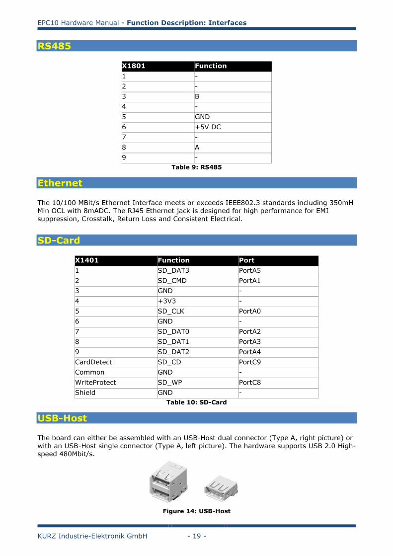
USB-Host
The board can either be assembled with an USB-Host dual connector (Type A, right picture) or
with an USB-Host single connector (Type A, left picture). The hardware supports USB 2.0 High-
speed 480Mbit/s.
Figure 14: USB-Host
EPC10 Hardware Manual - Function Description: Interfaces
KURZ Industrie-Elektronik GmbH - 20 -
USB-Devise
If the board is assembled with an USB-Host single connector (Type A), the board can be
extended with an USB device connector (Type B). The hardware supports USB 2.0 High-speed
480Mbit/s.
Figure 15: USB-Device
Reset/Wakeup
X1102 Function Port
1 WAKEUP WKUP
2 GND -
3 nRESET NRST
Table 11: Reset/Wakeup
Touch
The EPC10 offers two human interface touch solutions. For capacitive touch please refer to
Chapter 2.3 (System Controller) and appropriate datasheets from Microchip®
(www.microchip.com). The 4-Wire resistive touch is configured as follows:
X1603/X1604 Function Port
1 Touch_XP PortD20
2 Touch_XM PortD21
3 Touch_YP PortD22
4 Touch_YM PortD23
Table 12: Touch
EPC10 Hardware Manual - Function Description: Interfaces
KURZ Industrie-Elektronik GmbH - 21 -
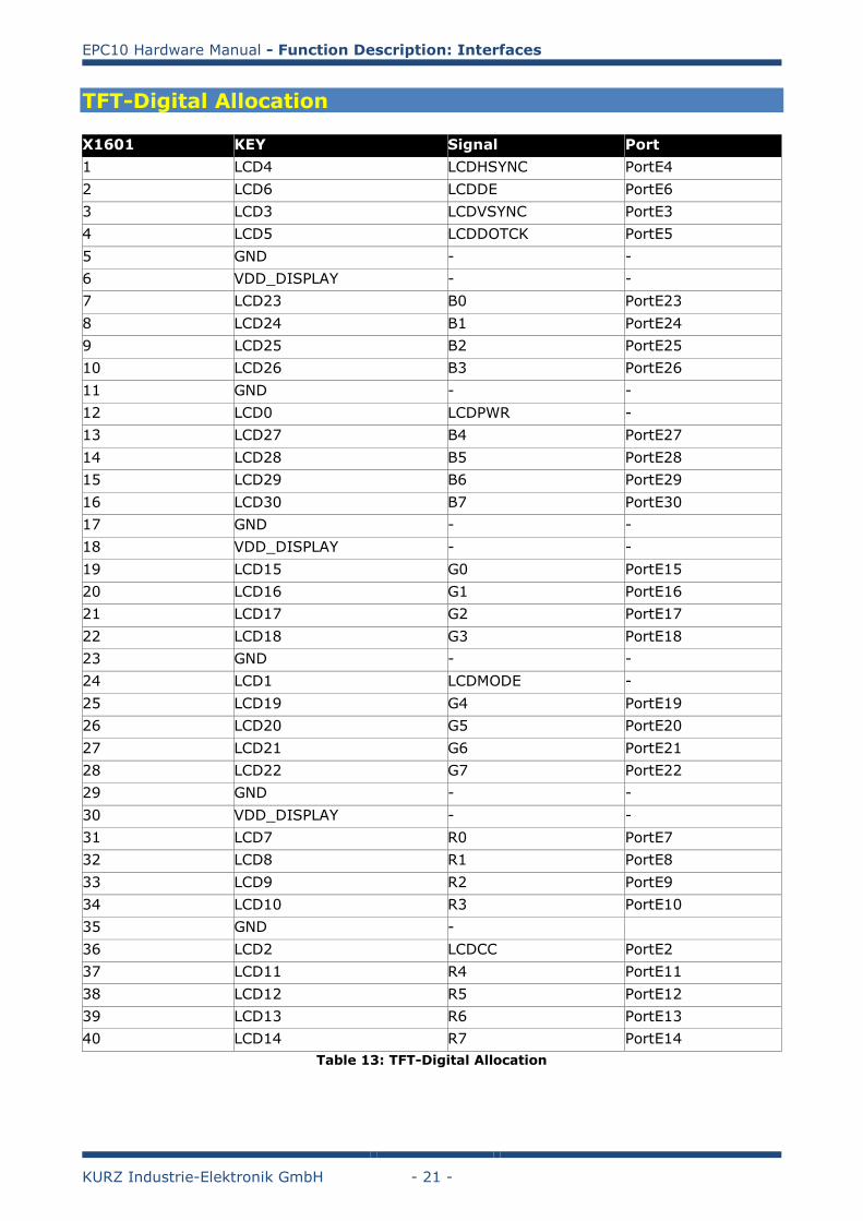
TFT-Digital Allocation
X1601 KEY Signal Port
1 LCD4 LCDHSYNC PortE4
2 LCD6 LCDDE PortE6
3 LCD3 LCDVSYNC PortE3
4 LCD5 LCDDOTCK PortE5
5 GND - -
6 VDD_DISPLAY - -
7 LCD23 B0 PortE23
8 LCD24 B1 PortE24
9 LCD25 B2 PortE25
10 LCD26 B3 PortE26
11 GND - -
12 LCD0 LCDPWR -
13 LCD27 B4 PortE27
14 LCD28 B5 PortE28
15 LCD29 B6 PortE29
16 LCD30 B7 PortE30
17 GND - -
18 VDD_DISPLAY - -
19 LCD15 G0 PortE15
20 LCD16 G1 PortE16
21 LCD17 G2 PortE17
22 LCD18 G3 PortE18
23 GND - -
24 LCD1 LCDMODE -
25 LCD19 G4 PortE19
26 LCD20 G5 PortE20
27 LCD21 G6 PortE21
28 LCD22 G7 PortE22
29 GND - -
30 VDD_DISPLAY - -
31 LCD7 R0 PortE7
32 LCD8 R1 PortE8
33 LCD9 R2 PortE9
34 LCD10 R3 PortE10
35 GND -
36 LCD2 LCDCC PortE2
37 LCD11 R4 PortE11
38 LCD12 R5 PortE12
39 LCD13 R6 PortE13
40 LCD14 R7 PortE14
Table 13: TFT-Digital Allocation
EPC10 Hardware Manual - Function Description: Interfaces
KURZ Industrie-Elektronik GmbH - 22 -
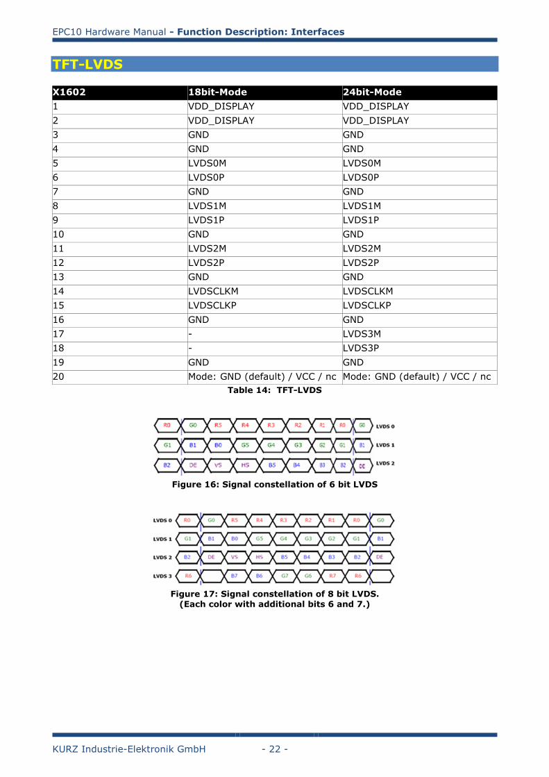
TFT-LVDS
X1602 18bit-Mode 24bit-Mode
1 VDD_DISPLAY VDD_DISPLAY
2 VDD_DISPLAY VDD_DISPLAY
3 GND GND
4 GND GND
5 LVDS0M LVDS0M
6 LVDS0P LVDS0P
7 GND GND
8 LVDS1M LVDS1M
9 LVDS1P LVDS1P
10 GND GND
11 LVDS2M LVDS2M
12 LVDS2P LVDS2P
13 GND GND
14 LVDSCLKM LVDSCLKM
15 LVDSCLKP LVDSCLKP
16 GND GND
17 - LVDS3M
18 - LVDS3P
19 GND GND
20 Mode: GND (default) / VCC / nc Mode: GND (default) / VCC / nc
Table 14: TFT-LVDS
Figure 16: Signal constellation of 6 bit LVDS
Figure 17: Signal constellation of 8 bit LVDS.
(Each color with additional bits 6 and 7.)
EPC10 Hardware Manual - Function Description: Interfaces
KURZ Industrie-Elektronik GmbH - 23 -
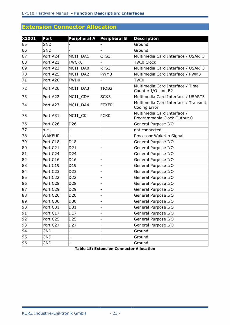
Extension Connector Allocation
X2001 Port Peripheral A Peripheral B Description
65 GND - - Ground
66 GND - - Ground
67 Port A24 MCI1_DA1 CTS3 Multimedia Card Interface / USART3
68 Port A21 TWCK0 - TWI0 Clock
69 Port A23 MCI1_DA0 RTS3 Multimedia Card Interface / USART3
70 Port A25 MCI1_DA2 PWM3 Multimedia Card Interface / PWM3
71 Port A20 TWD0 - TWI0
72 Port A26 MCI1_DA3 TIOB2 Multimedia Card Interface / Time
Counter I/O Line B2
73 Port A22 MCI1_CDA SCK3 Multimedia Card Interface / USART3
74 Port A27 MCI1_DA4 ETXER Multimedia Card Interface / Transmit
Coding Error
75 Port A31 MCI1_CK PCK0 Multimedia Card Interface /
Programmable Clock Output 0
76 Port C26 D26 - General Purpose I/O
77 n.c. - - not connected
78 WAKEUP - - Processor WakeUp Signal
79 Port C18 D18 - General Purpose I/O
80 Port C21 D21 - General Purpose I/O
81 Port C24 D24 - General Purpose I/O
82 Port C16 D16 - General Purpose I/O
83 Port C19 D19 - General Purpose I/O
84 Port C23 D23 - General Purpose I/O
85 Port C22 D22 - General Purpose I/O
86 Port C28 D28 - General Purpose I/O
87 Port C29 D29 - General Purpose I/O
88 Port C20 D20 - General Purpose I/O
89 Port C30 D30 - General Purpose I/O
90 Port C31 D31 - General Purpose I/O
91 Port C17 D17 - General Purpose I/O
92 Port C25 D25 - General Purpose I/O
93 Port C27 D27 - General Purpose I/O
94 GND - - Ground
95 GND - - Ground
96 GND - - Ground
Table 15: Extension Connector Allocation
EPC10 Hardware Manual - Function Description: Interfaces
KURZ Industrie-Elektronik GmbH - 24 -
CR2032 Battery
JTAG
EPC10 Hardware Manual - Function Description: Memory
KURZ Industrie-Elektronik GmbH - 25 -
Function Description: Memory
Memory Map
NAND
SDRAM
DataFlash