Enstrom 280C RFM (1998)
112
ATP INDEX COPYRIGHT 2008 COPYRIGHT IS NOT CLAIMED AS TO ANY PART OF AN ORIGINAL WORK PREPARED BY A UNITED STATES GOVERNMENT OFFICER OR EMPLOYEE AS PART OF THAT PERSONS OFFICIAL DUTIES OR BY ANY OTHER THIRD PARTY OFFICER OR EMPLOYEE AS PART OF THAT PERSONS DUTIES. "ATP" is a registered trademark of Aircraft Technical Publishers. All original authorship of ATP is protected under U.S. and foreign copyrights and is subject to written license agreements between ATP and its Subscribers. ALL RIGHTS RESERVED. NO PART OF THIS PUBLICATION MAY BE REPRODUCED, STORED IN A RETRIEVAL SYSTEM, OR TRANSMITTED IN ANY FORM BY ANY MEANS, ELECTRONIC, MECHANICAL, PHOTOCOPYING, RECORDING OR OTHERWISE, WITHOUT PRIOR WRITTEN PERMISSION OF THE PUBLISHER.
-
Upload
jeremiahjohnson -
Category
Documents
-
view
75 -
download
3
Transcript of Enstrom 280C RFM (1998)

ATPINDEX
COPYRIGHT 2008
COPYRIGHT IS NOT CLAIMED AS TO ANY PART OF AN ORIGINAL WORKPREPARED BY A UNITED STATES GOVERNMENT OFFICER OR EMPLOYEE ASPART OF THAT PERSONS OFFICIAL DUTIES OR BY ANY OTHER THIRD PARTY
OFFICER OR EMPLOYEE AS PART OF THAT PERSONS DUTIES.
"ATP" is a registered trademark of Aircraft Technical Publishers. All originalauthorship of ATP is protected under U.S. and foreign copyrights and is subject
to written license agreements between ATP and its Subscribers.
ALL RIGHTS RESERVED. NO PART OF THIS PUBLICATION MAY BEREPRODUCED, STORED IN A RETRIEVAL SYSTEM, OR TRANSMITTED IN ANY
FORM BY ANY MEANS, ELECTRONIC, MECHANICAL, PHOTOCOPYING, RECORDING OR OTHERWISE, WITHOUT PRIOR WRITTEN PERMISSION OF THE
PUBLISHER.

Aircraft Technical Publishers Customer Service
South Hill Drive 6AM-5PM PST M-Flrz Brisbane, CA 94005 (800)227-4610
ATP Grid Index to Manufacturer’s Publications:
Enstrom HelicopterModel 280C
Flight Manual
Section Tooic
General Information
Title PageList of Chapters (Table of Contents)
Record of Revisions
Record of Temporary Revisions
Section 1 General
Section 2 Limitations FAA Aproved
Section 3 Normal Procedures FAA Approved
Section 4 Emergency Malfunction Procedures FAA Approved
Section 5 Performance FAA Approved
Section 6 Weight and Balance
Section 7 Aircraft and System Description
Section 8 Aircraft Handling, Servicing and Maintenance
Section 9 Operational Information
Section 10 SupplementsWet/Dry Dispersal System Supplement No. 1
Float Landing Gear Supplement No. 2
External Loads Supplement No. 3
02/22/2008 Copyright Aircraft Technical Publishers Page 1 of 2
EN 0136 FM)
Section Topic
Snowshoe Supplement No. 4
~kjnk End of Index "k
02/22/2008 Copyright Aircraft Technical Publishers Page 2 of 2
EN 0136 FM

IV1 FGI
INTRO

ii;rH´•T
MANUAL
:´•i::-:::-:
__
I"D(ii: ’I
EN~TROM280C

THIS IS THE 280C
QRIGINAL.As. Received By
ATP
Manufactured by The Enstrom Helicopter Corporation,Menominee, Michigan. This manual pertains to Model 280C heli-
copters S,N. 1124 and up or as modified in accordance with
Enstrom Drawing 28-100005.
Ownership of the Turbocharged 280C Helicopter will provide
you with a smooth, distinctive, and comfortable mode of flight
geared to the concept of modern transportation. For business or
pleasure, the field of operations is practically unlimited, as point-
to-point travel can be accomplished from either prepared or
unprepared areas. The distinctive appearance of the 280C is
symbolic of prestige and its high performance capabilities.Under the graceful lines of the 280C is a ruggedly constructed
helicopter designed for easy servicing, minimum maintenance,
dependability and economical operation.
Copyright 1976 Enstrom Corporation, Menominee, Michigan, U.S.A.
Report No. 28´•*C-016

RECORD OF REVISIONS
MFG REV
NO DESCRIPTION ISSUEDATE ATPREVDATE INSERTEDBY
Original Issue 5/22/98 3/5/08 SHY
2/22/2008

RECORD OF TEMPORARY REVISIONS
TEMP ATP REV INSERT DATE REV REMOVE
REV NO DESCRIPTION ISSUE DATE DATE BY REMOVED INCOR BY
2/22/2008
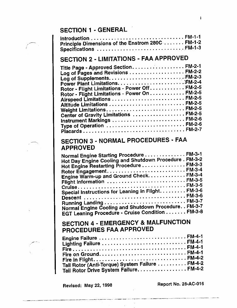
SECTION 1 GENERAL
Introduction FM-1-1
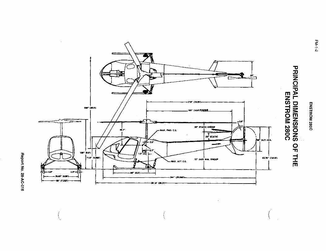
Principle Dimensions of the Enstrom 280C FM-1-2
Specifications FM-I-3
SECTION 2 LIMITATIONS FAA APPROVED
Title Page Approved Section. FM-2-1
Log of Pages and Revisions FM-2-2
Log of Supplements...... .IFM-2-3
Power Plant Limitations........ .:~FM-2-4
Rotor Flight Limitations Power Off............ FM-2-5
Rotor Flight Limitations Power On............ FM-2-5
Airspeed Limitations FM-2-5
Altitude Limitations FM-2-5
Weight Limitations........ FM-2-5
Center of Gravity Limitations FM-2-5
Instrument Markings FM-2-6
Type of Operation FM-2-6
Placards........... ´•´•´•´•´•FM-2-7
SECTION 3 NORMAL PROCEDURES FAA
APPROVED
Normal Engine Starting Procedure.........´• ´•´•´•´•FM-3-1
Hot Day Engine Cooling and Shutdown Procedure FM-3-2
Hot Engine Restarting Procedure.......... FM-3-3
Rotor Engagement FM-3-4
Engine Warm-up and Ground Check............ FM-3-4
Flight Information FM-3-5FM-3-5Cruise.........´•´•´•´•´•´•´•´•´•´•´•´•´•´•´•´•´•´•´•´•´•´•´•´•´•´•´•´•
Special Instructions for Leaning in Flight......... FM-3-6
FM-3-6Descent.......´•´•´•´•´•FM-3-7Running Landlng.......´•
Normal Engine Cooling and Shutdown Procedure..FM-3-7
EGT Leaning Procedure Cruise Condition....... FM-3-8
SECTION 4 EMERGENCY MALFUNCTION
PROCEDURES FAA APPROVED
Engine Failure FM-4-1
Lighting Failure FM-4-1FM-4-1Fire´•´•´•´•´•´•´•´•´•´•´•´•´•´•´•´•´•´•´•´•´•´•´•´•´•´•´•´•´•´•´•´•´•´•´•´•´•´•~
Fire on Ground........ FM-4-1
Fire in Flight FM-4-2
Tail Rotor (Anti-Torque) System Failure.......... FM-4-2
Tail Rotor Drive System Failure........... FM-4-2
Revised: May 22, 1998 Report No. 28-AC-016
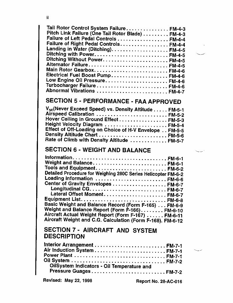
Tail Rotor Control System Failure. FM-4-3Pitch Link Failure (One Tail Rotor Blade) FM-4-3Failure of Left Pedal Controls FM-4-4Failure of Right Pedal Controls. FM-4-4Landing in Water (Ditching). FM-4-5Ditching with Power, FM-4-5Ditching Without Power.. FM-4-5Alternator Failure. FM-4-5Main Rotor Gearbox. FM-4-6Electrical Fuel Boost Pump FM-4-6Low Engine Oil Pressure, FM-4~6Turbocharger Failure FM-4-6Abnormal Vibrations
SECTION 5 PERFORMANCE FAA APPROVED
V,,(Never Exceed Speed) vs, Density Altitude FM-5-1Airspeed Calibration FM-5-2Hover Ceiling In Ground Effect FM-5-3Height Velocity Diagram FM-5-4Effect of Off-Loading on Choice of H-V Envelope FM15-5Density Altitude Chart FM-5-6Rate of Climb with DensityAltitude FM-5~7
SECTION 6 WEIGHT AND BALANCE
Information,
Weight and Balance. FM-6-1Tools and Equipment. FM-6-2Detailed Procedure for Weighing 2800 Series Helicopter FM-6-2Loading InformationCenter of Gravity Envelopes FM-6-7
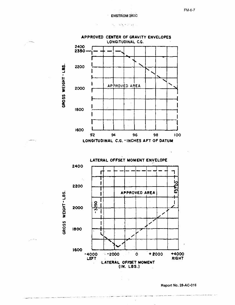
Longitudinal CG. FM-6-7Lateral Offset Moment. FM-6-7
Equipment List, FM-6-8Basic Weight and Balance Record (60001 F1165) FM-6-9Weight and Balance Report (Form F1166)........ FM-6-10Aircraft Actual Weight Report (Form F-167) FM-6-11Aircraft Weight and C.G. Calculation (Form F-168). FM-6-12
SECTION 7 AIRCRAFT AND SYSTEMDESCRIPTION
Interior Arrangement FM-7-1Air Induction System FM-7-1Power Plant FM-7-1Oil System FM-7-2
OilSystem Indicators Oil Temperature andPressure Guages FM-7-2
Revised: May 22, 1998 Report No, 28-AC-016

Engine Controls ´•´•´•´•´•´•´•´•´•´•FM-712
Throttle. ´•´•´•´•´•´•´•´•´•´•´•´•´•FM-7-2
Mixture Control FM-7-2
Magneto Switch FM-7-2
Ignition Safety Switch FM-7-2
Starter Button FM-7~2
Master Switch FM-7-2
Turbocharger ´•´•´•´•´•´•´•´•´•´•´•´•FM-7-3
Exhaust Gas Temperature System FM-7-3
Cabin Heat FM-7-3
Clutch Engaging Lever ´•´•´•FM-713FM-7-3Fuel Systems..........:
Auxiliary Fuel Pump Switch FM-7-4
Fuel Quantity Indicator ´•´•FM-7-4
Fuel Flow- Fuel Pressure Indicator FM-7-4
Transmission System FM-7-4
Main Rotor Transmission Temperature Ind5cator FM-714
Tail Rotor Transmission. FM-7-4
Rotor System............. FM-7-5
Main Rotor FM-7-5
Tail Rotor ´•´•´•´•´•´•´•´•´•´•´•´•´•FM-715
Rotor Tachometer FM-7-5
Flight Controls......... FM-7-5
Cyclic Control FM-7-5
Stabilizer FM-7-5
Collective Pitch Control. FM-7-5
Directional Control Pedals..........´•´•´• ´•´•´•´•´•FM-7-5
Flight Instruments FM-7-6
Airspeed Indicator ´•´•´•´•´•´•FM-7-6
Altimeter. ´•´•´•´•´•´•´•´•´•´•´•´•´•FM-7-6
Compass ic.tb;:::::::::::::Free Air Temperature Ind
Electrical Power Supply System FM-7-6
Direct Current Power System FM-7-6
Key to Instrument Panel FM-7-7
Electrical Power Panel............ FM-7-8
Lighting Equipment........´• FM-7-8
Position Lights. FM-7-8
Anti-Collison Lights...........´• FM-7-8
Landing Lights FM-7-8
Ground Handling Wheels. FM-7-8
Baggage Compartment FM-7-9
SECTION 8 AIRCRAFT HANDLING, SERV1CING
AND MAINTENANCE
Gound Handling FM-8-1
Mooring FM-8-1
Revised: May22,1998 Report No. 28-AC-016

Transporting FM-8-1Storage I... FM-8-1Hoisting FM-8-2Jacking FM-8-2Exterior Paint FM-8-2Windows and Doors,
Upholstery and Carpets. FM-8-2Landing GearShock Struts. FM-8-2Air Cleaner or Filter FM-8-3Lights FM-8-3Battery FM-8-3Dampers Main Rotor FM-8-3Transmission- Main Rotor FM-8-3Transmission- Tail Rotor, ,,FM-8-3Lubrication FM-8-3Excessive GreaseMain Rotor and Tail Rotor Blades FM-8-4Fuel, FM-8-4Oil
Cooling System FM-8-5Required FAA Forms FM-8-5Preflight Inspection FM-8-6
Exterior. FM-8-6Interior FM-8-7
Exterior Inspection Diagram FM-8-9
SECTION 9 OPERATIONAL INFORMATIONSolo Flight FM-9-1Taxiing FM-9-1Takeoff FM-9-1Normal Takeoff to Hover FM-9-1Normal Takeoff from Hover FM-9-2Maximum Power Takeoff...,,,. FM-9-2Maximum PowerTakeofffrom ConfinedArea FM-9-3Crosswind Takeoff......~ FM-9-3Normal Approach for Landing, FM-9-4Steep Approach FM-9-4Landing Landing Site Evaluation FM-9-4Wind Direction and Velocity FM-9-5Normal LandingCrosswind Landing FM-9-5Flight Characteristics Handling and Stability..... FM-9-6Maneuvering Flight FM-9-7Hovering Flight FM-9-7Student Training, FM-9-7Noise Abatement FM-9-7Leaning with an EGT FM-9-8
Revised: May 22, 1998 Report No. 28-AC-016

ColdWeather Operation......: FM-9-8Blade Tape 1 FM-9~9Loss of Tail Rotor Effectiveness FM-9-9Fuel Flow vs. Noule Pressure Chart FM-9-10Average Cruise Performance. FM-9-11
SECTION 10 SUPPLEMENTS
Wet/Dry Dispersal System Supplement No. 1
Section i-General FM-10-1-1Section 2 Limitations FM~10-1-1
V,,MPH IAS Placard. FM110-1-2Section 3 Normal Procedures
Preflight Check FM110-I-2Section 4 Emergency and Malfunction Procedures
Liquid Jettison FM-10-1-2Loss of Power’ FM10-112Loss of Tail Rotor.........;. FM-10-1-2Vibration FM-10-1-2Spreader Malfunction.......
i FM110-1-3Section 5 Performance
List of Figures. FM-10-1-3V,,vs. Density Altitude. FM-10-1-4Mover Ceiling in Ground Effect FM-10~1-5Airspeed Calibration. FM-10-1-6Height Velocity Diagram. FM-10-1-7
Section 6 Weight and Balance.........: FM-10-1-8Section 7 System Description and Installation Instructions
Initial Installation FM-10-1-8Wet Dispersal System Installation FM-10-1-8Wet Dispersal System Removal............ FM-I0-1-9Dry Dispersal System Installation FM-10~1-9Dry Dispersal System Removal FM-10-1-9Return to Normal Category FM-10-1-9
Float Landing Gear Supplement No. 2
Section i-General... FM-10-2-1Section 2 Operating Limitations
Type of Operations FM-10-2-1V,,vs. MPH IAS Placard. FM-10-2-1
Section 3 Normal ProceduresRotor Engagement onWater FM-10-2-2Flight Information FM10-2-2Running Landing FM-10-2-2Base Altitude Change. FM-10-2-2
Section 4 Emergency ProceduresEngine Failure During Flight(Above 80 MPH) FM-10´•2-3Engine Failure During night(Below 80 MPH). FM-1~2-3
Revised: May 22, 1998 Report No; 28-AC-016

Section 5 PerformanceDefinition,Rate of Climb FM-10-2-3V,, vs, DensityAltitude Chart FM-10-2-5Airspeed Calibration Chart............., FM-10-2-6
Section 6 Weight and Balance
Operational Equipment. ............i.... FM-10-2-4Center of Gravity Limit Envelopes,,,.., FM-10-2-4
External Loads Supplement No, 3
Section i-General FM-10-3-1Section 2 Operating Limitations
Engine, ....,...,~FM-10-3-1Airspeed FM-10-3-1Altitude
Weight......:Center of Gravity FM-10-3-2Type of Operations, FM-1013-2V,, MPH IAS Placard FM-10-3-2
Section 3 Normal Procedures
Preflight Operation Check FM-10-3-2Static Electricity Discharge FM110~313Cargo Hook Operation FM-10-3-3
Section 4 Emergency Procedures FM-10-3-3Section 5 Performance Data............., FM-10-3-4Section 6 1 Weight and Balance..........., FM110-3-4
Optional Equipment. FM-10-3-4
Snowshoe Supplement No, 4
Section i-General FM-10-4-1Section 2 Operating Limitations
Airspeed FM-10-4-1Weight. .,,......~FM-10-4-1Center of Gravity FM-10-4~1
Section 6 Weight and Balance..........., FM-10-4-1Optional Equipment FM-10-4~1
Revised: May 22, 1998 Report No. 28-AC-016

FM-1-1
ENSTROM 280C
SECTION 1 GENER~
INTRODUCTION
This manual meets all FAA requirements for approved data and
this data is so designated. It also contains supplemental data
supplied by the Enstrom Helicopter Corporation.
In addition to this manual, the Enstrom Helicopter Corporationalso has available for your helicopter a Maintenance Manual and
a Parts Catalog. Both of these can be obtained from yourEnstrom dealer or from the factory.Periodic revisions are made to these manuals to incorporatechanges and additions. Service information is also issued to
owners of record in the form of:
Service information letters (informative and advisory)Service directive bulletin (mandatory)
Report No. 28-AC-016
.,_.,~..I.II(^---~I _-----´•r
I=a
ZO
m ~Esl2rV) O
P~ (*.01 -1 z
tor. I yOm "o
Z r
V)n*~K: DIDo, ~3 oj I (II /-M(. F~m). C.C. I 1 Oo O o
o Zrr Ilt*fK: O u,
,.g
O
to~- np,In
In
I~r nnr, ~m- Ir~tnD rrl~o)wm.DIYIO IO MU. AFT C.O.7 m
na~I I
0IUI
o
i

FM-1-3
ENSTROM 280C
~SPECIFICATION;S
Power Plant
Type Lycoming OpposedDesignation HIO-360-E1 AD
Cylinders 4
Normal Power 205 HP
Normal RPM 2900 RPM
Specific Fuel Consumption(Full Rich) .69 Ibs, hp/hr.
Oil 10 qts. 16 ibs. IWeight 322 Ibs.
Performance
Maximum Speed
VNE Power On 117 MPH to 3000 ft. Above3000 ft. see FM-5-1
Power Off Due to high rates of descent at
high forward speeds, sustainedautorotation speed is limited to85 MPH to 8800 ft. Above 8800
ft., see FM´•5-1.
Best Rate of Climb 57 MPH IAS at sea level;above sea level see FM-5-7
Normal Fuel Capacity 40 U.S. gal. at 240 Ibs.
Rate of Climb at Sea Level 1125 FPM
Hovering Ceiling IGE 8800 ft.
Standard Day 2350 Ib. G.W.Service Ceiling Above 16,000 ft.
Operating RPM
Engine 2750 2900
Tail Rotor 2504 (at 2900 engine RPM)Main Rotor 350 (at 2900 engine RPM)Main Rotor Autorotation Range 332 385
*Maximum FAA approved operating ceiling presently limited to 12,000 ft.
FAA Approval: Sept. 28, 1977
Revised: Feb. 23, 1993 Report No. 28-AC-016

FM-1-4
ENSTROM 280C
Ratios
Lower to upper pulley 1:157
Main Rotor Gear Box 1:7.154
Tail Rotor %ear Box 1:1
Engine to main rotor 8.277
Dimensions
Width (overall) 28’ 2"
Rotor diameter 32’
Height (overall) 9’
Length (overall) 27’ 8"
Cabin width at seat 58"
Tread-Landing Gear 7’ 4"
Rotor System
Number of blades,Main rotor 3
Cord-main rotor blade 9.5"
Disk area, main rotor 804 so. ft.
Main rotor RPM 350
Tail rotor diameter 4.67’
Number of blades, tail rotor 2
Chord, tail rotor blade 4.4"
Weight
Designed gross weight 2350 Ibs.
Empty weight (approx.) 1495 Ibs.
Useful load 855 Ibs.
C.G. travel 92" to 94.6" at 2350 Ibs.
92" to 100" at 2000 Ibs.
Report No. 28-AC-016

FM-2-1
ENSTRoM 280c
ORIGINAL
SECTION 2 LIMITATIONSAs Received By
A6P
ENSTROM MODEL 280C
H E LICOPTER
´•::i:::.:.::;.:: I:-:i:´•:::::i:iiii:ii::i:iiiiiiiii:.i:;:ii:::::i:i:i::;:
i::.::: ’ili´•ilii:i:;iii:
i:i:ii-i:i.::ii:iil iii:i:iiiiiliilii:~iiilijiiliiijiliil:il:iililiii::i:iiiiiiii::::::::::::::::j:::::::’::::::::::ii
i:i:::iij´•i’ii:i:i: :i’i:jiiii’;iiiiiiliiijl:iii$ilijiliiiiiiiill::.i´•:iiiiiiiiiii::l:l:I:l:´•:
I’::i:´•:: :::::::::j :-;ilij::i’i’li::l:::j::l:i:i:i:l:l:I:l,i;:i:iliijij:i:iiiijliiiiid)jijiil.::::~iiijii.i~iiii;iii:i j:l: II i: i: 1; i´•:´•i: ii;:il’:: ii:i:iiiiiili9~: i´•ii :-:--:i I~
:::i :::´•:iil:::: 1,’:iiiIiiiiijiili~iiili
ii~ii
I:´•:i.::::iiliii:iiiiji:iiiiiii:::i:Iili:iii::,~a iiiii
iiiiiiii:iiiiiiiiiiiiiiiiiliiii::iiiiiiiiiiiiii
’:I:::i:i:l:’i’:i:::::::iii’:’:::’’ iii;iil:I:aiiiiiiiaiili:::iiiiiiililiiiiiiiiiiiiii’:iijiiiiiiiiiiiiiiiiiiiiiiiiiiil’iili~iiiiiiiiiiijiE:::::´•:::::´•:´•:´•
..:il-: ´•´•i:i:i´• I:´•i´•.´•asi’::r:’:l:::’~
8B~
iiHliiii~lZ iiii,!l:ii.::;jjsiiciiii:ii:::ii::\::i-- iiei:i:iaiii´•.it-i:´•liiiii~lir:s
Type Certificate No. H1CE
Registration
Approved by
for Chief, Engineering and Manufacturing Branch
Flight Standards DivisibnGreat Lakes RegionFederal Aviation Administration
September 23, 1977
NOTE: Sections 2, 3, 4, 5 and 6 are F=AA approved. Section 10
includes supplements to the type certificate which are
FAA approved if so designated.
NOTE: This manual pertains to Model 280C helicopters S.N.
1124 and up or as modified in accordance with Enstrom
Drawing 28-100005.
FAA Approval: September 23, 1977 Report No. 28-Ac-016

FM-2-2
ENSTROM 2800
LOG OF PAGES AND REVISIONS
Rev.
No. Pages Description Date F.A.A. Approved’
FM Revised
1 10´•3´•1 External Load
FM Supplement
~0´•3´•2
FM
10-3-3
FM ca~2 2-7 Added placard
3-3 t and opetatio ~,V3-6 information s~
FM Added2-2 operational2-4 instructions, S~s
Bk~´•´•’2-5 information PL~2-7 and placard. E~53-33-53-67-3
FM v dded Blade Tape3-3 l4dded St~p6-e,
Pq4 8-4 dded Blade rape8-7 Bnformation9-9
*Approved for ManagerChicago Aircraft Certification Office
Central RegionFederal Aviation Administration
NOTE: All revisions are indicated by a black vertical line. I
FAA Approval: September 23, 19n
Revised: Nlay 22, 1998 Report No. 28-AC-016

FM-2-2.1
ENSTROM 280G
LOG OF PAGES AND REVISIONS
Aev.F.A.A. Approved’Pages Description Date
No.
ii Added AbnormalVibrations
4-71Added Page
1-3 Oil CapacityCorrected
3-3 "Center" added
3-7 Corrected word
9-1 Corrected ht~cI~
to 3 to 5 feetN
9-2 Changed wo rd i ng ;E
and deleted
9-3 reference to
pop-off valve
i-vi Revised Page B
M-2´•2.11FAA ApprovalNumbersc//M~c4,Y\
7 ;blFM-4-51Revised Emergency rLM-4-6 ocedure and Mov
M-4-7 ext, Added Page
M-9-9 IAdded Text
*Approved for ManagerChicago Aircraft Certification Office
Central RegionFedreal Aviation Administration
NOTE: All revisions are indicated by a black vertical line.
FAA Approval: September 27, 1977
Revised: May 22, 1998 Report No. 28-AC-016

FM-2-3
ENsTRbnn 2eoc
LOG OF SUPPLEMENTS
Supp.No. Pages Description Date F.A.A. Approved
Wetl~Dry1 8 5-5´•78
Dispersal System
FLOAT2 6
LANDING GEAR
Extema\ Loads3 2
Snowshoe7-28´•78 Pacg4 1
Supplement
*Approved for Chief, Engineering and Manufacturing Branch
Flight Standards Division
Great Lakes RegionFederal Aviation Administration
NDTE: All revisions are indicated by a black vertical line. I
Report No. 28-AC-016
FM-2-4
ENSTROM 2809
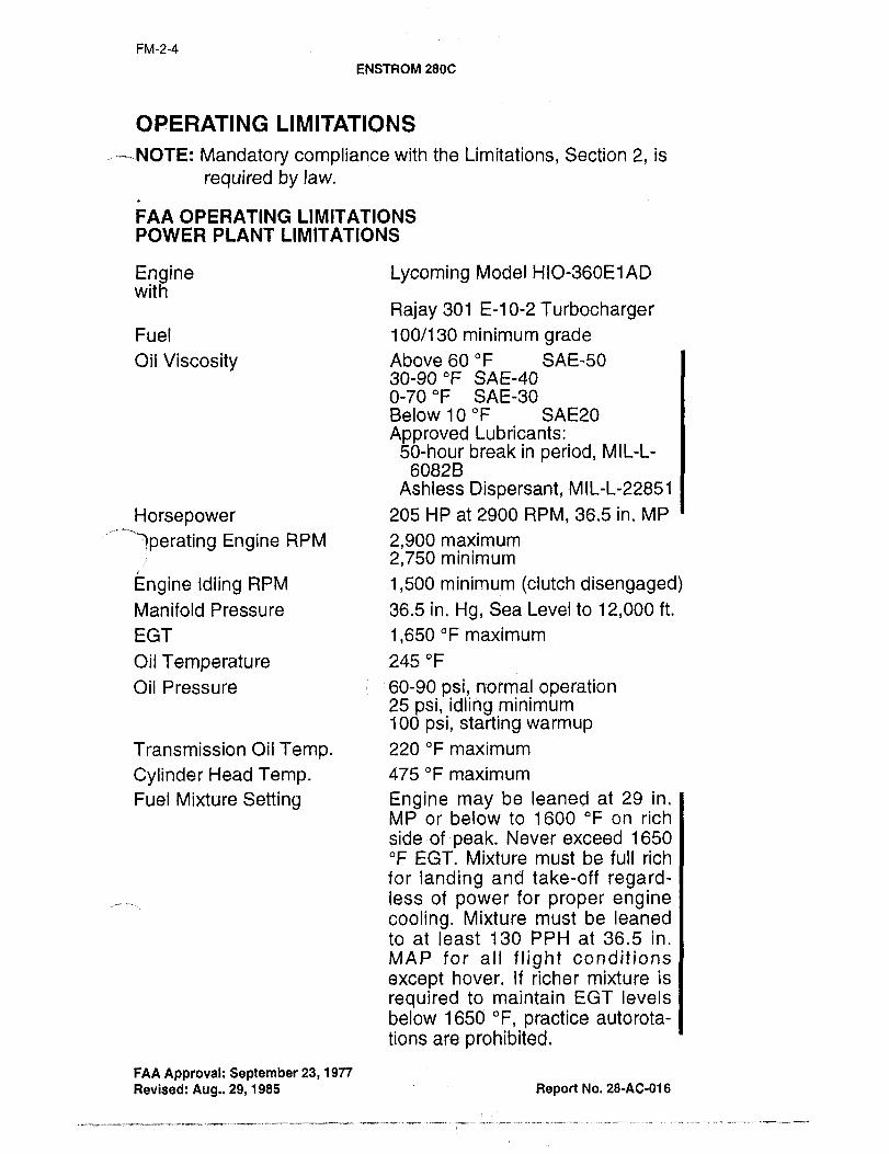
OPERATING LIMITATIONS
..´•´•----´•-.NOTE: Mandatory compliance with the Limitations, Section 2, is
required by law.
FAA OPERATING LIMITATIONSPOWER PLANT LIMITATIONS
Engine Lycoming Model l-llO-360E1ADwith
Rajay 301 E-10-2 TurbochargerFuel 100/130 minimum gradeOil Viscosity Above 60 "F SAE-50
30-90"F SAE-LFO0-70 "F SAE-30Below 10"F SAE20
Approved Lubricants:50-hour break in period, MIL-L-
60828Ashless Dispersant, MIL-L-22851
Horsepower 205 HP at 2900 RPM, 36.5 in. MP
’;"~‘‘qperating Engine RPM 2,900 maximum
2,750 minimum
Engine Idling RPM 1,500 minimum (clutch disengaged)Manifold Pressure 36.5 in. Hg, Sea Level to 12,000 ft.
EGT 1,650 "F maximum
Oil Temperature 245 "F
Oil Pressure :60-90 psi, normal operation25 psi, idling minimum100 psi, starting warmup
Transmission Oil Temp. 220 "F maximum
Cylinder Head Temp. 475 "F maximum
Fuel Mixture Setting Engine may be leaned at 29 in.
MP or below to 1600 "F on rich
Side of peak. Never exceed 1650
"F EGT. Mixture must be full richfor landing and take-off regard-less of power for proper enginecooling. Mixture must be leaned
to at least 130 PPH at 36.5 in.
MAP for all flight conditions
except hover. If richer mixture is
required to maintain EGT levels
below 1650 "F, practice autorota-
tions are prohibited.
FAA Approval: September 23, 1977
Revised: Aug.. 29, 1985 Report No. 28-AC-018

FM-2-5
ENSTROM 280C
ROTOR FLIGHT LIMITATIONS I(POWER OFF)
Maximum: 385 rpmMinimum 332 rpm
ROTOR FLIGHT LIMITATIONS (’POWER ON),__
Minimum: 332 rpmMaximum 350 normal operating
AIRSPEED LIMITATIONS
Never exceed speed: VNE: 117 mph IAS SL to 3000 ft
Hg´•For variations greater than 3000 ft.,
see
FM-5-1.
ALTITUDE LIMITATIONS
Maximum operating: 12,000 ft. density altitude.
NOTE: (Information only) Takeoffs and landings at 2350 Ibs.
gross weight were demonstrated during FAA typeinspection tests up to 7,000 ft. density altitude.
Operators should use appropriate caution above 7,00ft. density altitude and limit gross weight as required tL,__insure safe takeoffs and landings.
WEIGHT LIMITATIONS
Maximum approved weight: 2350 Ibs.
CENTER OF GRAVITY LIMITATIONS
Forward: 2350 Ibs. 92.0 in. station
Rearward: 2350 Ibs. 94.6 in. station
2200 Ibs. 96.7 in. station
2000 Ibs. 100.0 in. station
Lateral offset moment: 2350 Ibs. -3250, +3700 in Ibs.
below 2015 Ibs. See FM-6-6.
This helicopter is to be loaded in accordance with Section 6,
Loading Information.
NOTE: Lonciitudinal
Station 0 (Datum) is located 100 inches forward cents
line of main rotor hub.
Lateral
Station 0 (Datum) is airct~aft centerline, lateral moment
arms are positive right, negative left.
FAA Approval: September 23, 1977
Revised: August 29, 1985 Report No. 28-AC-016
FM-2-6
ENSTROM 289C
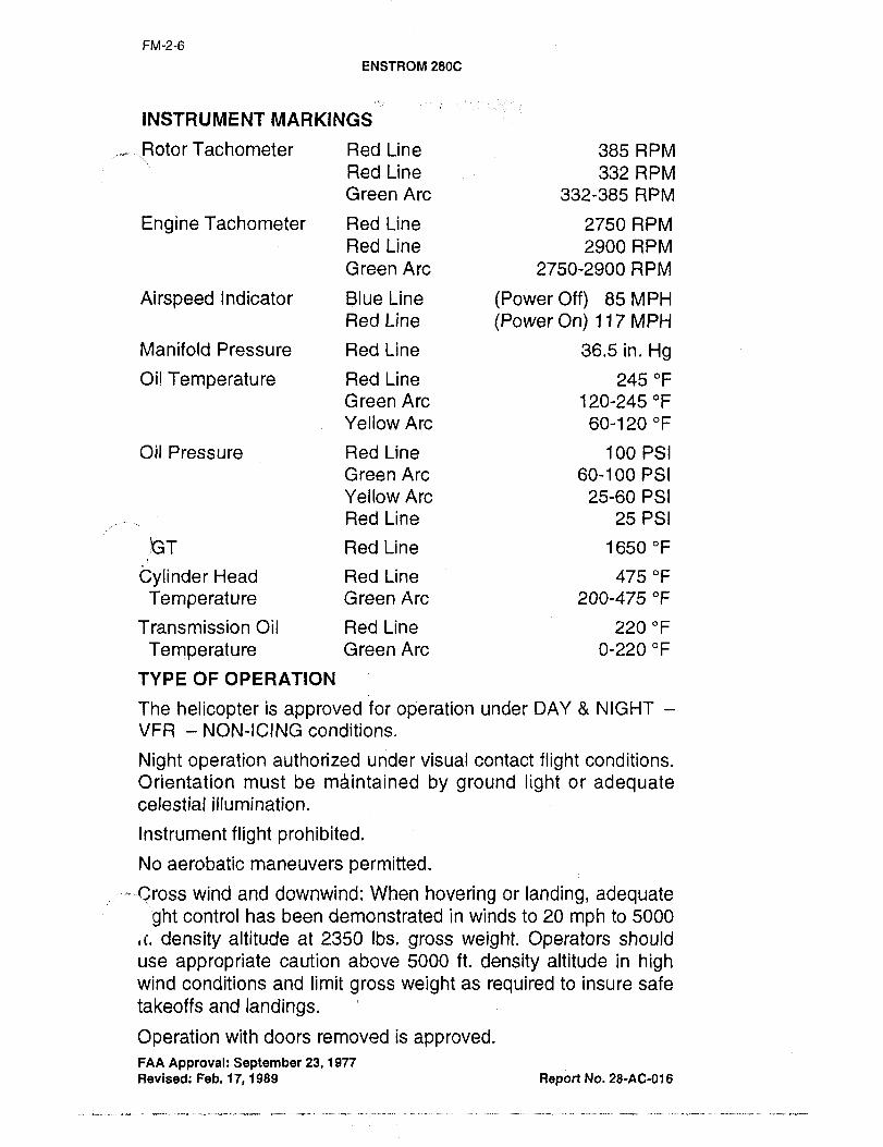
INSTRUMENT MARKINGS
.,..,.,,,..,_~Rotor Tachometer Red Line 385 RPM
Red Line 332 RPM
Green Are 332-385 RPM
Engine Tachometer Red Line 2750 RPM
Red Line 2900 RPM
GreenArc 2750-2900 RPM
Airspeed Indicator Blue Line (Power Off) 85 MPH
Red Line (Power On) 117 MPH
Manifold Pressure Red Line 36.5 in. Hg
Oil Temperature Red Line 245 "F
Green Are 120-245 "F
Yellow Are 60-120 "F
Oil Pressure Red Line 100 PSI
Green Are 60-100 PSI
YellowArc 25-60 PSI
Red Line 25 PSI
~GT Red Line 1650 "F
Cylinder Head Red Line 475 "F
Temperature Green Are 200-475 "F
Transmission Oil Red Line 220 "F
Temperature Green Are 0-220 "F
TYPE OF OPERATION
The helicopter is approved foy operation under DAY NIGHT
VFR NON-1CING conditions.
Night operation authorized under visual contact flight conditions.
Orientation must be m~intained by ground light or adequatecelestial illumination.
Instrument flight prohibited.
No aerobatic maneuvers permitted.
-´•-´•´•´•´•´•Cross wind and downwind: When hovering or landing, adequateght control has been demonstrated in winds to 20 mph to 5000
11. density altitude at 2350 Ibs, gross weight. Operators should
use appropriate caution above 5000 ft. density altitude in highwind conditions and limit gross weight as required to insure safe
takeoffs and landings.
Operation with doors removed is approved.FAA Approval: September 23, 1977
Revised: Feb. 17, 1989 Report No. 28-AC-016

FM-2-7
ENSTROM 280C
PLACARDS:
"THIS HELICOPTER MUST BE OPERATED IN COMPLIANCE
WITH THE OPERATING LIMITATIONS SPECIFIED IN THE FAP’
APPROVED ROTORCRAFT FLIGHT MANUAL.
AIRSPEED LIMITATIONS MPH:
NEVER EXCEEDISPEEDS MILES PER HOUR IAS
PRESSURE OUTSIDE AIR TEMPERATURE "F
ALTITUDE -20 0 20 40 60 80 100
SEA LEVEL 117 117 117 117 117 117 117
2000 117 117 117 117 117 114 109
4000 117 117 117 115 110 105 96
6000 117 116 111 105 96 87 78
8000 112 107 96 87 78 69 60
10000 99 88 78 69 59
12000 81 70 60
"NO SMOKING" (This placard not required when an approvedashtray is installed.)
"THIS HELICOPTER IS APPROVED FOR OPERATION UNDEI
DAY NIGHT VFR NON-ICING CONDITIONS ONLY.
"MAXIMUM WEIGHT IN THISCOMPARTMENT 60 LBS.
OBSERVE CG AND GROSS WEIGHT LIMITATIONS.
"COLLECTIVE FRICTION TO BE USED FOR GROUND OPER-
ATION ONLY" (This placard to be placed adjacent to the collec-
tive friction device.)
"LEAN TO 130 PPH AT 36.5 sN. MAP IN FLIGHT SEE
REVISED RFM." (This placard to be placed in view of the pilot.)
"STOW FLAT ON FLOOR BEFORE FLIGHT" (This placard to be
placed on clutch handle).
FAA Approval: September 28, 1977
Revised: August 29, 1985 Report No. 28-AC-016

FM-2-8
ENSTROM 2800
FOR NICKEL-CADMIUM ONLY
BATTERY TEMPERATURE ALERT
120 "F MONITOR BATTERY TEMPERATURE (AMBER LIGHT)
130 "F TURN OFF ALTERNATOR SW.
REDUCE ELECTRICAL LOAD, TURN ALT. SW. ON IF AMBER LT.
GOES OUT IN FLIGHT.
150 "F TURN OFF MASTER SWITCH.
(RED ARC) LAND AS SOON AS PRACTICAL. INSP. BATTERY
PER MANUF. INSTR. BEFORE FURTHER FLIGHT.
EACH 250 HR. INTERVALS PERFORM FUNCTIONAL
TESTS PER K.S. AVIONICS INSTRUCTIONS.
FAA Approval: September 23, 1977 Report No. 28-AC-016

FM-3-1
ENSTROM 280C
SECTION 3 NORMAL PROCeDURES
NORMAL ENGINE STARTING PROCEDURES
1. Seat belts fastened and doors.latched,
2. Fuel valve pushed in to turn on.
3. Collective full down and secured with the friction knob.
4. Heater as desire~ tin for OFF).
5. Cyclic stick cannon plugs secure.
6. Rotor clutch disengaged.
CAUTION: Although starting the helicopter with the rotor
clutch engaged will not damage the rotor sys-
tem, it will severely overload the starter motor.
7. Check compass full of fluid, no bubbles, and with a correc-
tion
8. Altimeter set to field elevation.
9. Radio(s) off.
10. All switches off.
11. Master switch and alternator on (alternator off if using an
APU start). Ignition switch on.
12. Throttle full open for engine prime only.
13. Mixture full rich.
14. Fuel boost pump on until: the fuel pressure gauge shows a
rise, then boost pump off.
15. Mixture idle cut off; throttle closed then cracked open
approximately 1/16", mags on both; depress starter, when
engine starts mixture in.
16. Fuel boost leave off during first cold start and ground run
to insure proper operation of engine driven fuel pump.
17. Check engine oil pressure if off the zero line within 30 sec-
ends..
18. Check amp meter gauge indicates a charge.
19. If APU start disconnect APU cable. Then alternator switch
on check for a charge indication on the amp meter.
20. Idle engine at 1450 to 1500 rpm.
FAA Approval: September 23, 1977 Report No. 28-AC-016
-~-´•´•´•----.-´•´•´•´•-´•:´•---I--´•´•-I´•´•-;-´• I´•-´•´•´•--´•--´•-

FM-3-2
ENSTRoM 280C
21. When oil pressure is 25 psi or above clutch may be
engaged.
CAUTION: On rare occasion the engine may backfire
through the induction system during a start pro-cedure. The backfire will not cause damage. to
the induction system but it could cause the
induction hose between the air filter and the fuel
injection servo unit to be disconnected due to
the backfire. It is recommended that should a
backfire occur during engine starting, a visual
inspection be accomplished by the pilot or
mechanic to assure that the hose is securely in
place before takeoff.
HOT DAY ENGINE COOLING AND
SHUTDOWN PROCEDURE
The following procedures are recommended for hot weather
operations, operations at high altitudes and when hot enginerestarts are anticipated. This shutdown procedure empties the
fuel lines within the hot engine compartment preventing fuel
vaporization within the lines. A successful engine start should
result when cool fuel is introduced into the lines immediatelyprior to engine cranking using the hot engine restarting proce-
dure. Operations at high density altitudes may require a mixture
control adjustment to ensure proper engine idle.
1. Collective pitch control full down and friction on.
2. Throttle idle position.
3. Fuel boost pump on.
4. Clutch disengaged, engine at full idle position.
5. Cyclic control centered with trim control.
6. F~uel shut-off valve closed tout). Residual fuel in the lines
will provide sufficient time at idle to ensure proper enginecool-down (two minutes or cylinder head temperature less
than 300 "F.).
NOTE: The red fuel system pressure low light will illuminate
soon after the fuel shut-off valve is closed. This is a
normal indication with the fuel shut-off valve closed
even though the boost pump is still operating.
FAA Approval: September 23, 1977 Report No. 28-AC-016

FM-3-3
7. VVhen engine stops bobst pump OFF.
8. Radios OFF.
9. Magnetos OFF.
10. Lights OFF.
11. Allswitches OFF.
12. Mixture idle cut OFF.
13. Throttle closed.
14. Master switch OFF.
HOT ENGINE RESTARTING PROCEDURE
1. Seat belts fastened and doors latched.
2. Collective full down and secured with friction.
3. Rotor clutch disengaged.4. Radios off.
5. All switches off
6. Master switch and alternator on. (Alternator off if using an
APU start).7. Fuel valve on (pushed in).
8. Throttle full open (for engine prime only).
9. Mixture control in full rich position.
10. Fuel boost pump on until fuel flow gauge shows a rise
(approximately 5-8 seconds), then boost pump off.
11. Return throttle to idle position and then crack open slightly,approximately 1/16".
12. Mixture to idle cutoff position.
13. Check throttle cracked, ignition switch on, mags on both
position.14. Depress starter, when engine fires, advance mixture control
to full rich position and turn boost pump on immediately to
preclude vapor lock.
15. Note engine idle RPM (with boost off) and turn fuel boost on.
Any difference in RPM noted indicates leaky idle mixture
plates (refer to Enstrom Service Letter No. 0069). Slowlylean engine with mixture control short of cutoff position. An
increase of 50 RPM indicates idle mixture improperly set
(refer to Enstrom Service Letter No. 0069).
16. Follow steps 17 through 21 of "Normal Engine StartingProcedure".
FAA Approval: September 23, 1977 Report No. 28-AC-016
--´•:´•´•--´•´•-----´•-´•´•-´•´•´•´•--;´•´•´•´•´•´•-´•---´•´•I´•´•:-----´•;-´•´•---;-´•;;-´•´•´•-´•´•´•-

FM-3-4
ENSTRoM 280C
ROTOR ENGAGEMENT
1. Check collective pitch full down. Friction on.
CAUTION: Collective friction tobe used for ground opera-tion only.
2. Tail rotor pedal neutral position.3. Center cyclic stick with trim switch. I4. Check aircraft vicinity clear of personnel and equipment.5. Check engine idle set at 1450 to 1500 RPM, then leave
throttle fixed in this position; do not add more throttle duringengagement.
6. Slowly and smoothly engage clutch handle at 1450 to 1500
RPM, allowing the engine RPM to bleed no lower than 1200
RPM. VVhen the rotor RPM reaches 100 RPM, fully engagecl utch.
NOTE: Clutch disengage warning light will go out when
clutch is fully engaged.
7. Place clutch handle in stowed position.
ENGINE WARMUP AND GROUND CHECK
1. Advance throttle to 1800 RPM and wait for cylinder head
temperature to reach low green or 200"F.
2. After reaching 200 PF. cylinder head temperature, slowlyadvance throttle to 2300 RPM until oil temperature reads
low yellow or 80 "F.
3. Check the magnetos using the following procedure:
a) Check all instruments for proper indication.
b) Set the E.G.T. gauge cursor red needle to the stabilized
indicated temperature. (This will be a reference tempera-ture during the mag test).
c) Switch from both mags position to left mag position and
note RPM drop and E.G.T. rise for five seconds. The
maximum allowable RPM drop is 125 RPM. The maxi-
mum allowable E.G.T. rise is 100 "F.
d) Return magneto switch to both allowing E.G.T. and RPM
to stabilize and repeat check on the right mag position.
e) The maximum permissible RPM differential between left
and right magnetos is 50 RPM without engine roughness.A differential of greater than 50 RPM and/or a drop in RPM
FAA Approval: September 28, 1977 Report No. 28-Ac-016

FM-3-5
ENSTROM 280C
greater than 125 RPM could indicate spark plug, sparkplug lead wire, or magneto problems.
f) An E.G.T. rise over 100 "F. during operation on individual
magneto indicates a magneto timing problem.
4. Gently close throttle to split tachometer needles to check
proper operation of over running clutch.
5. Check the following before take-off:
a) Check all instruments for proper indication.
b) Seat belts and doors latched.
c) Fuelon.
d) Fuel boost on. (Pump must be on at all times in flight).
e) Mixture full rich.
f) Fuel pressure warning green indication.
g) Clutch warning light push to test red light goes outIwhen released.
h) Release collective friction.
NOTE: Keep hand on collective and maintain down positionwhen friction lock is disengaged,
i) Set throttle friction as desired.
FLIGHT INFORMATION
1. Follow normal helicopter takeoff procedures at 2900 RPM.
(See height-velocity information, pages FM-5-4 and FM-5-5.
Linear interpolations may be used for operation between
S.L. and 7000 ft.
2. Best rate of climb speed varies with altitude, i.e., 57 MPH at
sea level decreasing to 52 MPH IAS at 7000 ft., and 49
MPH rAS at 12000 ft.
3. Do not exceed 36.5 inches of manifold pressure during~Sleeeeve3r6.5 inches of manifold pressure during the ICRUISE
Exhaust gas temperature, as shown on the Enstrom E.G.T. indi-
cator, should be used as an aid for fuel mixture leaning in cruis-
ing flight at 75% power or less, i.e., 28 inches manifold pressureand 2900 RPM. Do not exceed VNE as shown on placard and
the VNE versus altitude curve.
FAA Approval: September 28, 19n
Revised: Report No. 28-AC-016

FM-3-6
ENSTROM 280C
To obtain a best economy mixture, lean to 1650 "F E.G.T. To
obtain a best power mixture, lean only to 1550 "F E.G.T. Do not
exceed 1650 "F E.G.T. Operation on the lean side of peakE.G.T. is not approved. Also any change in altitude or power will
require a recheck of the E.G.T. indication.
SPECIAL INSTRUCTIONS FOR LEANING IN FLIGHT
a) The mixture must be leaned to at least 130 PPH at 36.5
inches MAP. Do not exceed 1650 "F E.G.T.
b) If mixture greater than 130 PPH is required to preventexceeding E.G.T. of 1650 "F, practice autorotation/powerchop are prohibited.
c) With mixture leaned as prescribed in (a) above, practiceautorotation/power reductions are to be performed as fol-
lows:
1) Close throttle smoothly all the way to the closed positionand hold on the stop, or:
2) Smoothly split needles and maintain engine RPM at 2000
or above.
3) Do not try to maintain throttle at intermediate positionsbetween fully closed and 2000 engine RPM as this may
cause inadvertent engine stoppage due to improperidle/mixture settings or faulty fuel servo.
NOTE: Since the 280C is equipped with a full-time tur-
bocharger, the turbocharged e’ngine is equippedwith an overboost warning light on the instrument
panel to warn the pilot of an overboost condition.
Transient overboost conditions which may triggerthe warning light may not show as overboost condi-
tions on the manifold pressure gauge. The manifold
pressure gauge red line is the determining factor in
ascertaining the magnitude of an overboost condi-
tion. Subject overboost conditions must be logged in
the engine log and inspections performed per
Lycoming Bulletin 369F.
DESCENT
CAUTION: Exercise care during descent to avoid exceeding
VNE´•
FAA Approval: September 28, 1977
Revised: Report No. 28-AC-016

FM-3-7
ENSTROM 280C
RUNNING LANDING
i. Maximum recommended ground contact speed is 35 MPH.Reduce speed on rough surfaces.
2. After ground contact, the helicopter must have zero forwardmotion before collective pitch is fully lowered.
NOTE: Due to the high friction characteristics of the heli-
copter’s hardened steel skid shoes, premature low-
ering of the collective must be avoided as rapiddeceleration and nose down pitching may result.
PRELANDING CHECKS
1. RPM 2900
2. Fuel quantity3. Instruments
4. Mixture full rich
5. Boost pump check on
NORMAL ENGINE COOLING AND SHUT-DOWN
PROCEDURE
1. Collective pitch full down and friction on
2. Throttle full off;
3. Fuel boost pump off
NOTE: Leave boost pump on until engine stops where tem-
perature and altitude conditions preclude smooth
idle engine operation with boost pump off.
4. Clutch disengaged, engine at full idle only
CAUTION: Clutch disengagement without throttle at full idle will
result in engine overspeed. Clutch disengagementis signaled by a red warnirig light on the instrument
console.
5. Cyclic control centered. I6. Note engine idle RPM (with boost off) and turn fuel boost on.
Any difference in engine RPM noted indicates leaky idle
mixture plates (refer to Enstrom Service Letter No. 0069).Slowly lean engine with mixture control short of cutoff posi-tion. An increase of 50 RPM indicates the idle mixture is
improperly set (refer to Enstrom Service Letter No. 0069).
7. Idle engine at 1800 RPM for 2 minutes or until cylinder head
temperature cools to 300 "F.
FAA Approval: September 28, 1977
Revised: Report No. 28-Ac-016

FM-3-8
ENSTROM 2809
8. Radios off.
9. Lights off.
10. Throttle full idle,
11. Mixture idle cut off.
12. When engine stops turning magnetos off.
13. All switches off.
14. Master switch off.
15. Fuel valve closed tout).16. Set collective one-half way up in its travel to unload lamiflex
bearings.17. Tie down main rotor and tail rotor if wind speed is expected
to go over 30 mph.
E.G.T. LEANING PROCEDURE CRUISE CONDITION
1. Attain the desired cruise flight condition.
2. Maintain a constant altitude and manifold pressure setting.3. Trim out cyclic forces to maintain level flight.4. Turn mixture control to attain desired lean E.G.T. setting.
NOTE: Do not exceed 1650 "F E.G.I. Under certain highaltitudes and high O.A.T.’s, near full rich mixtures
will be necessary to control cylinder head and
engine oil temperatures. If the temperatures are too
high, enrich in 25 "F E.G.T. increments until the
temperatures remain,jn the green arci
5. Any change in manifold pressure will require additional mix-ture adjustment.
FAA Approval: September 28, 1979
Revised: Report No. 28-AC-018

FM-4-1
ENSTRoM 280C
SECTION 4 EMERGEb\l%Y AND
MALFUNCTION PROCEDURES
ENGINE FAILURE
1. Enter normal autorotation and stabilize at 58 MPH (minimumrate of decent). See Height Velocity information, pages FM-5-4 and FM-5-5.iNOTE: Due to high rates of descent at forward speeds, sus-
tained autorotatiohlspeed is limited to 85 MPH to
8800 ft. Above 8800 ft., see FM-5-1.
Maximum glide distance in autorotation is attained
at 80 mph and 332 rotor rpm. (Reduce collective to
build RPM prior to touchdown.)2. Maximum recommended ground contact speed on prepared
surfaces is 35 mph. Reduce speed on rough surfaces.
3. After ground contact the helicopter must have zero forwardmotion before collective pitch is fully lowered.
NOTE: Due to the high friction characteristic of the heli-
copters hardened steel skid shoes, premature low-
ering of the collective must be avoided as rapiddeceleration and nose down pitching may result.
LIGHTING FAILURE
i. Landing can be made in case of landing light failure by illu-
mination from navigation lights. In case of a fon/vard landinglight failure, the taxi light will provide sufficient illumination to
land.
2. Instrument lighting is provided by eyebrow lights, internal
lights and map light. ~Vhile satisfactory landings have been
demonstrated without instrument illumination, a supplemen-tal light source (flashlight) is recommended.
FIRE
Fires may have several sources of origin. Generally they may be
classified as engine compartment or cabin compartment, fuel or
oil supported, or eledtrical.
FIRE ON GROUND
1. Shut off engine and all sw/tches.
2. Shut off fuel valve.
FAA Approval: September 23, 1977 Report No. 28-AC-016

FM-4-2
ENSTROM 280C
3. Determine source of fire and use fire extinguisher to extin-
guish any flames.
NOTE: Do not restart or fly aircraft until cause of fire is
investigated and corrected.
FIRE IN FLIGHT
If the presence of odor and/or smoke is detected, proceed as
follows:
1. Check instruments for correct reading.
2. Shut off master and alternator switchies.
3. Unlatch doors and let them trail open.
4. If smoke and odor persist, proceed to suitable area and land
aircraft.
5. If inspection of aircraft indicates presence of flames, shut off
engine and fuel valve and extinguish flames with fire extin-
guisher.NOTE: If flames are present, do not attempt to start to fly
aircraft until the cause of the fire has been investi-
gated and corrected.
Severe leakage of oil onto the exhaust system may cause con-
siderable smoke to enter the cabin. In such case aircraft should
not be flown until cause of leakage is investigated and correct-
ed.
TAIL ROTOR (Anti-Torque) SYSTEM FAILURE
There are two major possibilities for failure of the tail rotor (anti-torque) system and subsequent loss of directional control as fol-
lows:
1. Failure of any portion of tail rotor drive system that causes
stoppage or physical loss of the tail rotor blades.
2. Failure of any portion of the mechanisms that cause pitchchange of the tail rotor blades.
Upon loss of directional control, the pilot must immediatelydetermine the type of malfunction that has occurred (No. 1 or 2
above) and select the proper emergency procedure.
TAIL ROTOR DRIVE SYSTEM FAILURE
During hovering flight (aircraft will rotate rapidly to the rightwith full left pedal):
1. Cut throttle full off immediately (aircraft will slow down or
stop its rotation),
FAA Approval: September 23, 1977 Report No. 28-AC016

FM-4-3
ENSTROM 280C
2. Complete I
During cruising flight (aircraft will rotate to the: right with full left
peddle):
i. Power full off immediately´•,:enter autdrotation.2. Complete autorotatjon to nearest suitable area.
NOTE: If no suitable ar~a:i$;available within autorotative
distance, pilot shoulb proceed as follows after hav-
ing established stabilized autorotation with at least
60 MPH airspeed.
1. Increase collective pitch and power gradually (maintaining60 to 80 MPH airspeed) until yaw to the right reaches
approximately 45 degrees.
2. Continue flight in this fashion using cyclic stick for directional
control until suitable autorotational landing area is reached.
3. When 200 ft. altitude or more over suitable area, re-estab-
lish full autorotation and land.
TAIL ROTOR CONTROL SYSTEM FAILURE
NOTE: Loss of control may be caused by failure of left
pedal controls, right pedal cdntrols or failure of pitchlink to an individual ta’il rotor blade. On the Enstrom
tail rotor, it is normal (if uncontrolled or unattended)for the blades to assur’ne a nearly neutral pitch con-
dition. Upon loss of ability to fully control tail rotor
during cruising flight, proceed as follows:
PITCH LINK FAILURE (One tall rotor blade)
Aircraft will yaw to the right initially and will subsequently need
an abnormal amount of left pedal to maintain straight and level
flight since only one blade is providing anti-torque thrust.
1. Ply at low cruise power to suitable landing area and make
normal power approach.
2. Complete a slow (less than 35 mph) run on landing at low
power setting.
FAA Approval: September 23, 1977 Report No. 28-AC-016

FM-4-4
ENSTRoM 280C
FAILURE OF LEFT PEDAL CONTROLS
The direction and amount the aircraft yaws will depend on air-
speed and amount of power applied at time of failure. At highpower and high airspeeds the aircraft will yaw right. At all air-
speeds and low power settings below 23" Hg the helicopter will
yaw left. At low airspeeds where aerodynamic effects are negli-gible the helicopter will yaw left. At low airspeeds where aerody-namic effects are negligible the helicopter will yaw left to approx-
imately 30", hesitate briefly, and then accelerate into 360" turns
to the left. This condition can be avoided by adding power to 24"
Hg and accelerating to 50 mph. T~he helicopter can then be
flown to suitable area and landed using the procedure below.
1. Remove feet from both tail rotor pedals.
2. Maintain 24" Hg manifold pressure and 50 mph.
3. Fly to suitable area and complete a shallow power on
approach at 50 mph.
4. Manipulate power and collective pitch so that aircraft touch-
es down straight ahead at an airspeed of 0-10 mph. Reduce
power and collective cautiously as skids contact surface.
NOTE: Do not abort the emergency landing after airspeedhas diminished below 40 mph.
FAILURE OF RIGHT PEDAL CONTROLS
Tail rotor controls will be normal at power settings over 23" Hg.Power settings under 23" Hg will produce yaw to the left.
Proceed as follows:
1. Fly to suitable landing area at power setting of at least 23"
Hg.
2. Complete a shallow power on approach at 60 mph (do not
auto rotate)
3. Manipulate power and collective pitch so that aircraft touch-
es down straight ahead at an airspeed of 0-10 mph. Reduce
power and collective pitch cautiously as skids contact sur-
face.
NOTE: Application of power to over 23" Hg will make air-
craft more controllable. Therefore, landing attempt
may be aborted and new new approach initiated as
many times as necessary
FAA Approval: September 23, 1977 Report No. 28-AC-018
FM-4-5
ENSTRoM 280C
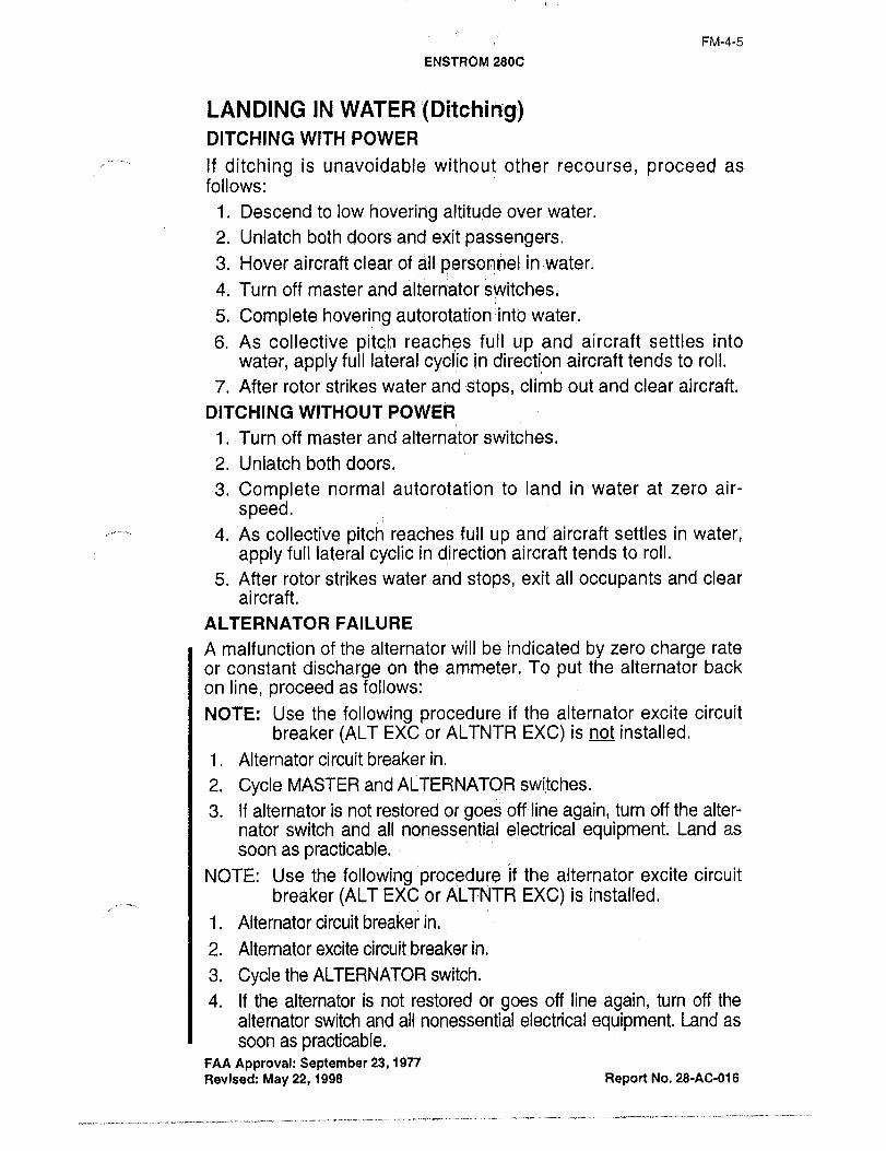
LANDING IN WATER (Ditching)DITCHING WITH POWER
If ditching is unavoidable without other recourse, proceed as
follows
1. Descend to low hovering altitude overwater.
2. Unlatch both doors and exit passengers.
3. Hover aircraft clear of ;i~il personnel in,water.
4. Turn off master and alternator 8witches.
5. Complete hovering autorotation :intbiwater.
6. As collective pitch reaches-full up and aircraft settles into
water, apply full lateral eyelid in direction aircraft tends to roll.
7. After rotor strikes water and :stops, climb out and clear aircraft.
DITCHING WITHOUT POWER
1. Turn off master and alternator switches.
2. Unlatch both doors.
3. Complete normal autorotation to land in water at zero air-
speed.4. As collective pitch reaches full up and aircraft settles in water,
apply full lateral cyclic in direction aircraft tends to roll.
5. After rotor strikes water and stops, exit all occupants and clear
aircraft.
ALTERNATOR FAILURE
A malfunction of the alternator will be indicated by zero charge rate
or constant discharge on the ammeter. To put the alternator back
on line, proceed as follows:
NOTE: Use the following procedure if the alternator excite circuit
breaker (ALT EXC or ALTNTR EXC) is not installed.
1. Alternator circuit breaker in.
2. Cycle MASTER and ALTERNATOR switches.
3. If alternator is not restored Or goes off-line again, turn off the alter-
nator switch and all nonessential electrical equipment. Land as
soon as practicable.NOTE: Use the following procedure if the alternator excite circuit
breaker (ALT EXC or ALTNTR EXC) is installed.
1. Alternator circuit breaker in.
2. Alternator excite circuit breaker in.
3. Cycle the ALTERNATOR switch.
4. If the alternator is not restored or goes off line again, turn off the
alternator switch and all nonessential electrical equipment. Land as
soon as practicable.FAA Approval: September 23, 19n
Revised: May 22, 1998 Report No. 28-AC-016
´•.-´•´•---;´•´•-.----´•-´•´•´•-´•;----´•-´•-´•´•´•-´•--;´•--´•I´•--´•-´•-;-;´•´•´•-´•I---´•´•--;´•´•-´•---´•--1´•´•´•--´•´•;´•;--´•´•´•´•------;-;´•----´•´•

FM-4-6
ENSTRoM 280C
MAIN ROTOR GEARBOX
If, in normal flight, the main rotor gearbox red line temperature is
exceeded, the helicopter should be landed at the next suitable
landing site.
ELECTRIC FUEL BOOST PUMP
Failure of the fuel boost pump will be evidenced by illumination of
the red low boost pressure warning light. In the event of a fuel
boost pump failure, the helicopter engine will continue to operatein’ a normal manner as long as the engine-driven fuel pump contin-
ues to function properly.
If the helicopter experiences a,fuel boost pump failure, terminate
the flight at the earliest practical time and have the malfunction
corrected prior to next flight.
CAUTION: If flight is continued after the fuel boost pump failure
and the engine-driven fuel pump malfunctions, the
engine will stop due to fuel starvation. Gravity fuel
feed is insufficient to supply fuel to the engine.
LOW ENGINE OIL PRESSURE
If low oil pressure is accompanied by normal oil temperature, there
is a possibility the oil pressure gauge or relief valve is malfunction-
ing. This is not necessarily cause for an immediate precautionarylanding. However, a landing at the nearest airport-heiiport would
be advisable to inspect the source of trouble.
If a total loss of oil pressure is accompanied by a rise in oil tem-
perature, there is good reason to suspect an engine failure is
imminent. Reduce engine power immediately and select a suitable
forced landing field.
TURBOCHARGER FAILURE (SEIZURE)
Turbocharger seizure will be evidenced by a power loss (manifoldpressure drop) if operating at manifold pressures above ambient
atmospheric pressure. It should be possible to maintain level flightat reduced airspeeds and altitude as the engine will then be oper-
ating essentially as a non-turbocharged engine with manifold pres-sure available essentially equal to ambient atmospheric pressure.A power check should be performed to confirm power available for
landing. A landing should be accomplished as soon as practicable.Plan for and perform a high altitude type (running) landing, see
page FM-3-7.
FAA Approval: September 23, 1977
Revised: May 22, 1998 Report No. 28-AC-016

FM-4-7
ENSTROM 280C
ABNORMAL VIBRATIONS:´•
Vibrations in this helicopter can usually be classified as either low
frequency or high frequency. Low frequency vibrations are
generally caused by the main rotor system while the highfrequency vibrations usually originate from the engine, drive
system, or tail rotor. Any abnormal vibratians are an indication that
something is not correct and should be referred to a mechanic
before further flight. If a vibration suddenly appears during a flight,it is an indication that somethingi has suddenly changed. The
helicopter should be landed as soon aS practical and inspected to
find the cause of the vibrations. After the cause of the vibration
has been identified, the pilot and the mechanic can determine
whether the helicopter can be safelyflown or should be repairedon the spot. An abnormal vibration is reason to get the aircraft
down as soon as pdss’ii~le bu~ th~? prlot;~nuqt ~ISP use caution and
select the safes~ poss~ landi’ng’sit~, working around wires,people and otherobstrJctions.
;I´• i
FAA Approval: September 23, 1977
Revised: May 22, 1998 Report No. 28-AC-016

FM-5-1
ENSTROM 2800
SECTION 5 PERFORMANCE
V never exceed VS. DENSITY ALTITUDE
(Vne demonstrated at 2750 engine rpm)2350 Ib. gross weight
Max. Approved12000
10000
lL
8000
D
u Icl 8000
I 1 \S4000
$I I h2000
S.L
-200020 40 60 80 100 120
Indicated Airspeed MPH
FAA Approval: September 23, 1977 Report No. 28-AC-0~6

FM-5-2
ENSTROM 280C
AIRSPEED CALIBRATION
120
too
a:5’
80
wwa
v,60
ouJC 40
a
0 20
0 20 40 60 80 100
INDICATED AIR SPEED M.P.H.
NOTE: Indicated speeds below 20 MPH are not reliable
FAA Approval: September 23, 19n Report No. 28-AC-016

FM-5-3
ENsTRonn 23dC
H~VER CEILING IN GROUND EFFECT
314~ FOOT SKID HEIGHT
13000
Max: Approved- Ceiling12000
Y, 10000
\I\
8000
B
L sooo
I I standard Day4000
Max. Approved Weight2000 1 1 (2350 Lbs.)
S.L.
1000 1800 2000 2200 2400
Gross Weight Lbs.
FAA Approval: September 23, 1977 Report No. 28-AC-016

FM-5-4
ENSTROM 280C
HEIGHT VELOCITY DIAGRAM
(Tests conducted on prepared surfaces)2350 LB. GR. WT.
AVOID OPERATION IN THIS AREA
600O.G.E. Hoover May Be Precluded ByAtmospheric Conditions In This Area.
SAFE OPERATING AREA600
Note:
Critical points were demonstrated
at S.L. 7000 Ft Hdu
Intermediate altitude curves
rr. 400 were developed analytically
i´•Racommendcd Takeoff Proflk
300 ~CIr
JQ) :t iC
P
r 200o,
I
JUss c´•ution in
100 area to avoid
IEDnt´•e~ .I 1´•ll role;Guard with ground.
0 20 40 60 120
Indicated Airspeed MPH
FAA Approval: September 23, i 977 Report No. 28-40-016
FM-5-5
ENSTROM PEjOC
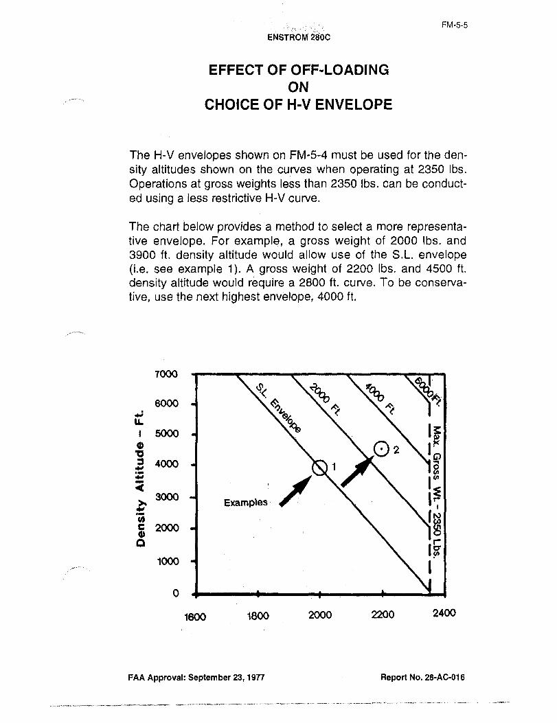
EFFECT OF OI=F-LOADING
ON
CHOICE OF HIV ENVELOPE
The H-V envelopes shown on FM-5-4 must be used for the den-
sity altitudes shown on the curves when operating at 2350 Ibs.
Operations at gross weights less than 2350 Ibs. can be conduct-
ed using a less restrictive H-V curve.
The chart below provides a method to select a more representa-tive envelope. For example, a gross weight of 2000 Ibs. and
3900 ft. density altitude would allow use of the S.L. envelope(i.e. see example 1). A gross weight of 2200 Ibs. and 4500 ft.
density altitude would require a 2800 ft. curve. To be conserva-
tive, use the next highest env’elope, 4000 ft.
7000
~B ~B8000 ;IC
ci ;r ;C
IL
5000
Q1 ~02C)
u4000 1~
r~ooo
B Examples
U)S XX~Ot
o r
1000
1600 1800 2000 2200 2400
FAA Approval: September 23, 1977 Report No. 28-AC-016

FM-5-6
ENSTROM 288C
DENSITY ALTITUDE’ CHART
SET ALTIMETER TO 29.92 fN. HG.
WHEN READING PRESSURE ALTITUDE15,000
14,000
13,000 ~65/I
~2:
2~11 ,000
cP(j:
r10,000 p
c
9000
soow
o 8000 -o
t I Y I2’000I> rn
7000 C~rn, ,o~~Tb‘
Z 6000
O
5000
4000
3000
2000
2
1000
s.L.
--20 -10 0 10"C 20 30 40 50
0 Ib 20 30 40 50 60 78 80 90 100110120
"F
OUTSIDE AIR TEMPERATURE
FAA Approval:September 23, 1977 Repsrt No, 28-AC-816
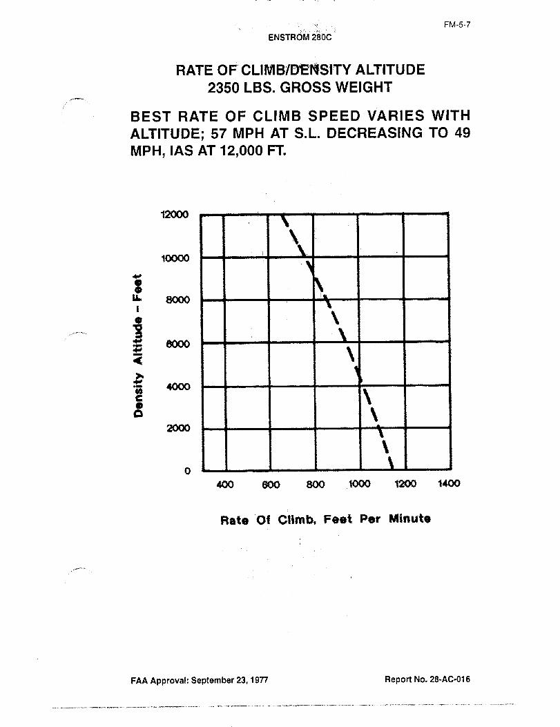
FM-5-7
ENSTRd~ 2~bC
RATE OF’;CLI ALTITUDE
2350 LBS. GROSS WEIGHT
BEST RATE OF CLIMB SPEED VARIES WITH
ALTITUDE; 57 MPH AT S.L. DECREASING TO 49
MPH, IAS AT 12,000 FT
12000
10000
a. 8000
a I Ieoos
4000
6 11 I i ~t2000
400 800 800 fOOo 1200 1400
Rate, Ot Climb, Feet Per Minute
FAA Approval: September 23, 1977 Report No. 28-AC-016

FM-6-1
ENSTROM 280C
SECTION 6 WEIGHT BALANCE
INFORMATION
All helicopters are designed for certain limit loads and balance
conditions. Changes lin equipment which affect the empty weightcenter of gravity must be recorded in the aircraft and engine logbook. It is the responsibility of the helicopter pilot to ensure that
the helicopter is loaded properly. The empty weight, emptyweight C.G. and useful loads are noted on the weight-balancesheet included in this Manual for this particular helicopter.
The longitudinal and lateral c.g. range for theModei 280C varywith gross weight. Satisfactory aircraft handling qualities have
been established throughout the c;g. envelopes shown on pageFM-6-8 of this manual. Although the envelopes presented cover
a wide range of typical loading conditions, pilots must calculate
any unusual loading conditions to insure that the aircraft c.g.
range for the Model 280C vary with gross weight. Satisfactoryaircraft handling qualities have been established throughout the
c.g. envelopes shown on page FM-6´•8 of this manual. Althoughthe envelopes presented cover a wide range of typical loadingconditions, pilots must calculate any unusual loading conditions
to insure that the aircraft c.g. remains in the approved envelope.Sample calculations are shown on pages FM-6-6 and FM-6-7 for
reference.
The lateral c.g. limit is defined in terms of lateral moment in that
the calculations of lateral c.g. is not part of the primary aircraft
weight and balance records. Lateral moment is the algebraicsummation of the left and right hand loads times their respectivelateral moment arms. A sample calculation is shown on pageFM-6-7 for reference. The aircraft centerline is used as the
datum reference. Left lateral moment arms considered negative;right lateral moment arms are considered positive.
WEIGHT AND BALANCE
The remdvai or addition of:fuel or equigment results in changesto the center of gravity and weight,of the aircraft, and the per-missible useful load is affected accordingly. The effects of these
changes must be investigated in all Gases to eliminate possibleadverse effects on the aircraft’s flight characteristics.
Report No. 28-Ac-016
-;´•r´•--´•´•---´•-´•--´•---------´•------´•-1-´•´•--´•´•-~---
11.´•-~-.
FM-6-2
ENSTROM 280C
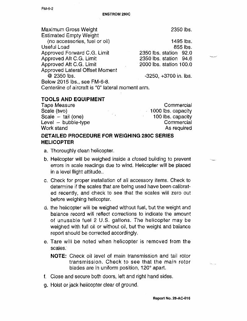
Maximum Gross Weight 2350 Ibs.
Estimated Empty Weight(no accessories, fuel or oil) 1495 Ibs.
Useful Load 855 Ibs.
Approved Forward C.G. Limit 2350 Ibs. station 92.0
Approved Aft C.G. Limit 2350 Ibs. station 94.6
Approved Aft C.G. Limit 2000 Ibs. station 100.0
Approved Lateral Offset Moment
2350 \bs. -3250, +3700 in. Ibs.
Below 2015 Ibs., see FM-6-8.
Centerline of aircraft is "O" lateral moment arm.
TOOLS AND EQUIPMENT
Tape Measure Commercial
Scale (two) I 10001bs.capacityScale tail tone) 100 Ibs. capacityLevel bubble-type Commercial
Work stand As requiredDETAILED PROCEDURE FOR WEIGHING 280C SERIES
HELICOPTER
a. Thoroughly clean helicopter.
b. Helicopter will be weighed inside a closed building to preventerrors in scale readings due to wind. Helicopter will be placedin a level flight attitude..
c. Check for proper installation of all accessory items. Check to
determine if the scales that are being used have been calibrat-
ed recently, and check to see that the scales will zero out
before weighing helicopter.
d. the helicopter will be weighed without fuel, but the weight and
balance record will reflect corrections to indicate the amount
of unusable fuel 2 U.S. gallons. The helicopter may be
weighed with full oil or without oil, but the weight and balance
report should be corrected accordingly.
e. Tare will be noted when helicopter is removed from the
scales.
NOTE: Check oil level of main transmission and tail rotor
transmission. Check to see that the main rotor
blades are in uniform position, 120" apart.
f. Close and secure both doors, left and right hand sides.
g. Hoist or jack helicopter clear of ground.
Report No. 28-AC-016
FM-6-3
ENSTdbM;28dC
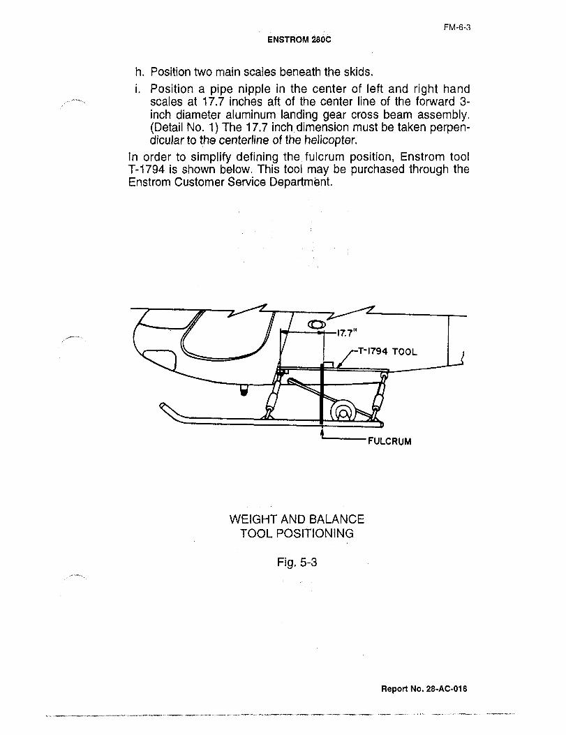
h. Position two main scales beneath the skids.
i. Position a pipe nipple in the center of left and right hand
scales at 17.7 inches aft of the center line of the forward 3-
inch diameter aluminum landing gear cross beam assembly.(Detail No. 1)The 17.7 inch dimension must be taken perpen-dicular to the centerline of the helicopter.
In order to simplify defining the fulcrum position, Enstrom tool
T-1794 is shown below. This tool may be purchased through the
Enstrom Customer Service Department.
lf.7"
T-1794 TOOL
ZFULCRUM
WEIGHT AND BALANCE
TOOL POSITIONING
Pig. 5-3
Report No. 28-AC-016

FM´•6-4
ENSTROM 280C
Fig. 1 ORIGINAL
As Received ByATP
j. Height of tail to be adjusted for level.
k. Level for and aft to be taken at lower pylon tube, left side, so
identified. (Detail No. 2). Fig. i.
i. Lateral level taken at lower forward pylon tube
m. Small scale will be located under tail rotor at the center line of
the tail rotor output shaft, Fig. 2.
n. Using jack, raise or lower tail as required to level the aircraft
along the longitudinal axis, paying attention to the level on the
longitudinal and lateral pylon tubes.
o. Read and record weight from each of three scales.
p. Calculate weight and center of gravity on attached form, with
weight date. Empty weight will be ’dly weight.’
q. All items added or subtracted will be listed on the attached
form with weight, are, and moment.
Rspon Na, 28-AC-016

QRIGINALFM-6-5
As Received ByATP
Fig. 2
CAUTION: Weight and measurement headings are critical.
Double check results.
r. Remove helicopter from scales.
CAUTION: Do not remove curbing, jack, nipples, blocks, etc.,from scales. These items constitute tare weight.
s. Read and record tare weight from each of the three scales. An
official weight and balance report is prepared in connection
with each helicopter presented for air-worthiness certification
at the Enstrom Cbrporation. All tt-iese reports are marked
"actual weight."t. This weight and balance report, and equipment list will be pre-
pared and supplied with each helicopter.
u. Use Form No. F-165 (page FM-6-10) Basic Weight and
Balance Report to give you a continuous history of weightchanges throughout the life of your helicopter.
Report No. 28-AC-016
FM-6-6
ENSTROM 280C
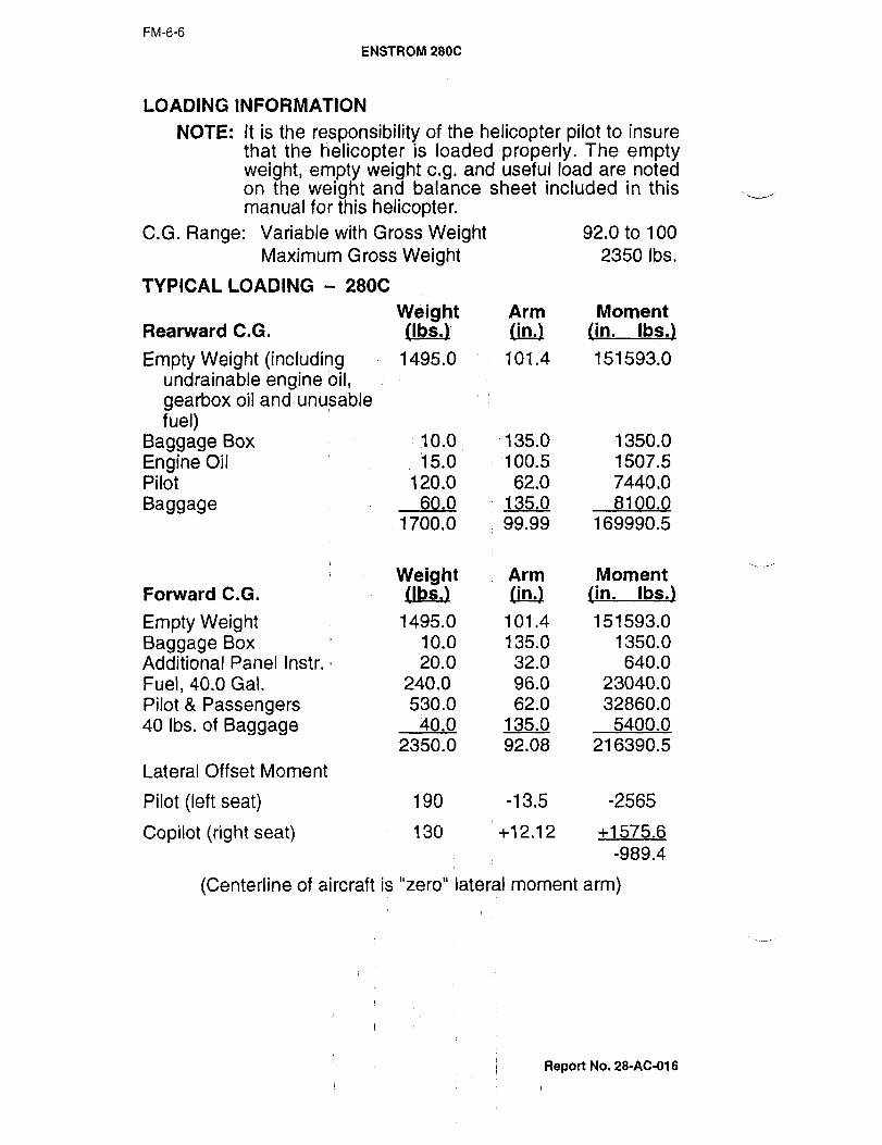
LOADING INFORMATION
NOTE: It is the responsibility of the helicopter pilot to insurethat the ~elicopter is loaded properly. The emptyweight, empty weight c.g. and useful load are notedon the weight and balance sheet included in thismanual for this helicopter.
C.G. Range: Variable with Gross Weight 92.0 to 100
Maximum Gross Weight 2350 Ibs.
TYPICAL LOADING 280C
Weight Arm MomentRearward C.G. /Ibs.) tin.) tin. Ibs.)
Empty Weight (including 1495.0 101.4 151593.0
undrainable engine oil,gearbox oil and unusable
fuel)Baggage Box 10.0 ;135.0 1350.0
Engine Oil 15.0 100.5 1507.5
Pilot 120.0 62.0 7440.0
Baggage 60.0 135.0 8100.0
1700.0 99.99 169990.5
Weight r
Arm MomentForward C.G. (Ibs,) tin.) tin. Ibs.)
Empty Weight 1495.0 101.4 151593.0
Baggage Box 1 10.0 135.0 1350.0
Additional Panel Instr. 20.0 32.0 640.0
Fuel, 40.0 Gal. 240.0 96.0 23040.0
Pilot Passengers 530.0 62.0 32860.0
40 Ibs. of Baggage 40.0 135.0 5400.0
2350.0 92.08 216390.5
Lateral Offset Moment
Pilot (left seat) 190 -13.5 -2565
Copilot (right seat) 130 +12.12 +1575.6
-989.4
(Centerline of aircraft is "zero" lateral moment arm)
Report No. 28-AC-016
FM-6-7
ENSTFPOM 2800
APPROVED CENTER OF GRAVITV ENVELOPESLONGITUDINAL C.G.
2400
2350--i--
q 2200
2OOO1 I IPPROVED P~!EP.
1800
1600
92 94 96 98 100
LONGITUDINAL C.G. -INCHES AFT OF DATUM
LATERAL OFFSET MOMENT ENVELOPE
2400
1
2200
ui 1 I I I APPROVED AREA
I~q~’"
IsOO
v
leOO-4000 1 12060 6 2000 +4000LEFT
L*tEAAL OrmfUOYENTRIGHT
(IM. LBS.)
Report No. 28-40-016

FM-6-8
ENSTROM 280C
ENSTRO~ 280C EOUIPMENT LIST
Serial No.
FAA Approved Regislraticin No. Date
Check DaleNo. Item Wt. Arm
On O11
tMSTAUMENfS AEQUtAED
Altimeter 1 1.2 11 36
Airspeed 1 .5 36Tachometer 1 1.3 1 36Manifold Fuel Pressure 1.5 36Inslrument Cluster :i 2.0 36
Oil TemperatureOil PressureGear Box TemperatureCylinder TemperatureFuel QuanlityAmmeter
Compass I t´•o 40
OAT Gauge I 0.5 55
Ball Bank Indicator’E.G.T. Gaupet 0.5 36
OPTlONAL EOUIPMENT I
1 Night lighting equipment (includiog combination
strobe and position lights, internally lit instrument
cluster)2 Map tight (Aeq’d for night flight) .5 80
3 8 day clock 1 .5 36
4 nourmeter .75 88
5 Soundproofing6 Defroster F28A. F28C
7 Strobe lightsi F28A
8 Float build up
9 Center radio console (F28A, F28C)(O CargoHook11’ Extra head set 2.0 8012 Cabin heater detroster combination 280, 280C 3.5 46
13 Snow shoe installation 18.0 100.914 Cabin heater (F28A, F28CI 4.1 36.015 Baggage comparlmenl 10.0 (35.016 Flotation gearlwith hardware
17 Dual controls 12.0 50
18 Floor carpet, Int, trim 8 headliner 6.0 65.019 Fed. 12V. twin speaker-siren 11.3 1´•7920 Litter kit-single 1 24.0 100.021 King KT 76 transponder 4.0 i 34.022 Shoulder harness wlreel single 3 81
23 Shoulder harness wlreel double 6 8224 First aid kit 5.2 13525 Ashtrays 8 lighter
I
I ’´•o 32.0
26 Fire extinguisher 1 5.7 80.027 External power unit (APU) 1.0 75.028 Narco com 11 AH wlintercom I 4.0 34.0
29 Narco nav It 1 3.5 32.0
30 Narco ADF i 40 4.3 33.03\ Narco OME \90 6.6 34.0
32 Narco ATSOA transponder 4.0 34.033 King KR86 ADF 3.9 34.0
34 Gyco horizon model R.C. Alien 25 3.4 32.0
35 1 RCA-15A-3 directional pro 2.3 1 32.036 King KX1758 NAVICOM 1 7.0 34.0
37 ADF 140 loop 6 sense antenna 3.1 138.0
38 Presidential doors (door pockets) 1 6.0 60.0
39 Instantaneous vertical speed indicator 1.3 34.040 Aim 200 directional gyro 3.8 34.041 Antenna (vor) I 1.3 194.0
42 Narco DGO-lO 1 4.7 32.043 Daul landing light (Req’d for night l(lght) 1 3.2 25.044 King KA 85 wiindicator
I
I 1 7.0 39.0
45 Chadwicle tank
46 Ground handling wheel(s) 1 13.0 104.7
47 King Kl-225-01 indicator ~.3 34.0
48 Natco NAV 14 2.25 34.049 Narco ELT 1 3.3 135
’Sisnderd equipment not required by FaA. I´•pat No.
Report No. 28-AC-016

Item Weight added Weight removed Running basic total o SItem cc’
Date Description of article or modification s hNo. In Out Weight ArmlMom.lWeightlArm Mom.lWeight(C.G. IMom. R
~o it QIragACTUAL DELIVERED WEIGHT AND BALANCE DATA I 1 I I a,
rr V)o,J
Oi
m~r:
o II m
v,C)"I 11. 2~"-I(D n
Z~ zo
Z go
DpI;
ivOD
ro
o oP’P
ZO
Zlm
o 3)r Zma
co P Oo 3 Oo
OI n,
i z 1 I 1 I 1 I I I I 1 I I I I I II 3J
bNca
i coo 71
o Ib c~ ir,cr, cb

FM-6-10
ENSTROM 2800
looa
CRaroRHue
Lca Ilo.ts
C~d
O
6~Q ~L*UI t9dO SLOI)
~WD
WeWHO YIBOH~
STATIO~ srimajrl
.Model Serial No. Regittretion No.
FWD. c/B limit 92.0’" AFal. clg limit 98,0"
Weigh point 8cele-lbf. Tare Net wt. Arm Moment x 1000
Left gear (WL)
Right gear IWR)
Tail (WTI
Total
WT (320.0) (WL WR) (93.446)LCG
WT WL WR
Date Weighed by
Report No. 28-ACOi 6

FM-6-11
ENSTROM 280C
AIRCRAFT ACTUAL WEIGHT REPORfModel Serial No. keg. No.
Standard equipment not installed Optional surplus equipment in
at weigh-in aircraft at weigh´•in
Moman’t X Moment XItem No. Wt. Arm 000in./lbs. Item No. Wt. Arm 11000 in./l
Total Total
Weighing witns~ed by c
I Date
Fgtm No. F´•167
Report No. 28-AC-016
´•´•´•--´•´•´•´•-´•----;´•´•´•´•-´•´•´•´•´•-;-´•´•;---´•-´•´•r´•´•´•--´•;´•´•--

FM-6-12
ENSTROM 280G
AIR.CRAFT WEIGHT AND C. G. CALCULATIONModel Serial No. Peg. No.
Weight Arm Moment
Ibs. in. 1000 in./lbs.
Weight las weighed)
Less: optional 8 surplus weight
Plus: missing std. equipment
Compu tad
Total weight empty std. aircraft
Actual
Plus: engine oil
Plus: optional equipment kits
Total basic weight
Fo~m No. F-188
Report No. 28-AC-016

FM-7-1
ENSTROM 280C
SECTION 7 AIRCRAFT AND SYSTEM
DESCRIP~ION
One of the first steps in obtaining the utmost performance, ser-
vice, and flying enjoyment from your 280C, is to familiarize your-self with its equipment, systems, and controls.
The Enstrom 280C Helicopter is designed for high performance,mechanical simplicity, and maxiri~um versatility. By virtue of
component longevity and minimum maintenance requirements,the 280C enjoys the lowest operating cost of any helicopter. The
rugged, patented rotor head, combined with the (51 Ibs. each)rotor blades, gives unheard of stability and excellent autorota-
tional characteristics.
INTERIOR ARRANGEMENT
The cabin interior is a full, thr’ee-place,j side-by-side seatingarrangement with a spacious 581’ width for maximum pilot and
passenger comfort and safety. The instrument panel is on the
vertical plane for more natural scanning and is convenientlylocated for dual pilot viewing. Excellent visibility is offered
throughout the tinted Plexiglas windshield and doors with over-
head and lower deck windows. Extra-width, swing-open doors
close securely with simple-to-operate safety lock handles. The
helicopter can be flown with either left, right, or both doors off.
AIR INDUCTION SYSTEM
The air induction system consists of a filtered non[ram air intake
located within the engine compartment. It incorporates a spring-loaded, automatic alternate air source.
POWEk PLANT
An Avco Lycoming HIO-360-E1AD 205 hp engine is used in this
helicopter. The engine is a direct drive, four cylinder, fuel inject-ed, horizontally opposed, air cooled engine. This engine incor-
porates features for turbochargingl Platinum spark plugs are
supplied with the engine.
NOTE: It is recommended that the appropriate LycomingOperator’s Manual be consulted prior to any adjust-ment or repair to the engine.
Report No. 28-AC-016

FM-7-2
ENSTROM 2800
OIL SYSTEM
The Lycoming engine employs a wet sump lubrication systemhaving a capacity of 8 quarts. The engine oil pump circulates the
oil through a remote mounted oil cooler to;provide cooling.lt is
located on the right-hand side of the engine compartment. A
thermostatic bypass and pressure relief valve are supplied as
standard equipment. Restricted pressure engine oil is also circu-
lated through the turbocharger bearing housing. A separateengine scavenge pump returns the oil to the engine sump. A
bayonet-type oil quantity gauge:with graduated markings is partof the oil filler cap and is accessible through the left fuel drain
access door.
The total oil system has a capacity of 10 quarts. This includes
the oil in the engine, oil filter, ~oil cooler, and oil lines.
Oil System Indicators-Oil Temperature and Pressure Gauges.Standard type gauges are provided for both the engine oil tem-
perature and oil pressure indications. Both gauges are marked
to provide visual engine operating limitations and are located on
the instrument panel.
ENGINE CONTROLS
Throttle. A twist-grip type throttle is located on the collective
pitch control stick for direct control of engine power. It is manual-
iv connected to the fuel servo-throttle valve on the engine.
Mixture Control A vernier mixture control knob is provided on
the instrument console. This vernier control incorporates the fea-
tures of a standard push-pull cable. Full rich is in the "in" posi-tion. Full lean is in the "out" position. The vernier feature allows
a screw type of adjustment to fine tune any preset mixture posi-tion.
Magneto Switch. The magneto switch is a key-operated switch
located on the left side of the switch circuit breaker panel. For
starting, place the switch in the "Both" position.
Ignition Safety Switch. This switch closes the circuit to the
starter button on the collective control.
Starter Button. The starter button is located on the end of the
collective control. Push to engage.
Master Switch. The master switch is located on the left side of
the switch circuit breaker panel. It is a single-throw, two-positionswitch.
Report No. 28-AC-018

FM-7-3
TURBOCHARGER
The turbocharger unit has only one moving part, a rotating shaft
with a turbine shell on one end, a compressor impeller on the other,all precision balanced and each contained in its own housing. The
turbine wheel, driven by exhaust gas energy, drives the impellerwhich compresses intake air to a density equivalent of near sea
level and delivers it to the engine intake. This increased volume of
air allows the engine to "breath" with the same volumetric efficiencythat it does at low levels. The engine can produce the equivalentpower at all altitudes up to12,000 feet density altitude.
EXHAUST GAS TEMPERATURE SYSTEM
The exhaust gas temperature, as shown on the panel mounted indi-
cator, is used as an aid for fuel mixture leaning in cruising flight.The panel indicator is red-lined at 1650 "F. The exhaust tempera-ture probe is located on the exhaust stack just before the inlet to the
turbocharger. This allows an actual: temperature measurement of
the exhaust gases that are delivered into the turbocharger unit.
CABIN HEAT
The cabin heat control is located at the left-hand side of the pilot’sseat on the forward face of the seat structure. By moving the control
in or out, the operator regulates the amount of cabin heat throughtwo output louvers located on the seat structure just above the
lower deck windows.
CLUTCH ENGAGING LEVER
The clutch engagement lever is located at the right side of the pilot’sseat on the forward face of the seat structure. The clutch lever is
provided as a means of engaging and disengaging the rotor drive
system.The rotor drive system is engaged by pulling the clutch lever
upward and rearward until the lever hits the stop and the warninglight goes out. The handle can then be stowed by lifting it straightup and pivoting it down to the floor. When it is in the stowed posi-tion, the handle should lie flat on the floor. If it does not lie flat on
the floor in the stowed position, the clutch rigging should be
checked as described in Section 8 of the Maintenance Manual. The
clutch lever must be stowed whenever the rotor drive system is
engaged.
FUEL SYSTEM
The system consists of two interconnected 20 US gallon fuel tanks,which feed simultaneously to the engine. The tanks are located on
the left and right side of the aircraft over the engine compartment.
Revised: August 29, 1985 Report No. 28´•AC-016

FM-7-4
ENsTROM 2800
The tanks have a total fuel capacity of 40 US gallons, with a total of
two gallons unusable fuel, one gallon unusable fuel in each tank.
Each fuel tank is gravity fed to a central distributing line which con-
nects to the electric boost pump and engine driven pump. The fuelcontrol located on the firewall next to the pilot’s left shoulder. Each
tank has an individual: drain valv~ in the bottom. There is also a
main gascolator filter located aft of the firewall in the engine com-
partment. The control is on the right-hand side of the engine com-
partment and extends beyond the side panel.
Auxiliary Fuel Pump Switch The fuel boost pump switch and
fuel pressure warning lights are located on the switch circuit
breaker panel. The green warning light will stay illuminated as
long as the fuel boost pump is operation. The red light will illumi-
nate at any time the fuel boost pump-is shut off or fails to func-
tion properly.Fuel Quantity Indicator. The fuel quantity gauge continuouslyindicates the total quantity of fuel. It is hooked up through a sim-
ple type liquidometer float located in theright-hand fuel tank. A
translucent strip on each tank provides a direct, visual indica-
tion of fuel level.
Fuel Flow-Fuel Pressure Indicator. The fuel pressure providespounds per hour and pressure readings of the fuel as delivered
to the flow divider. The indicator is marked for normal operatingrange from 0 to 160 pounds per hours and 0 to 25 psi index
lines in 5 psi increments.
TRANSMISSION SYSTEM
The main transmission unit provides an 8.277 reduction ratio
between the engine and the main rotor. The transmission incorpo-rates a free-wheeling unit in the upper pulley assembly which is
mounted on the pinion input shaft. The free-wheeling unit providesa disconnect from the engine in the event of a power failure and
permits the main and tail rotors to rotate in order to accomplish safe
autorotation landings. Six pints of S.A.E. 90 wt. E.P. gear oil are
used in the transmission. The main rotor transmission has a sightgauge which is located on the aft right-hand side and is visible
through an opening in the baggage compartment or the right access
panelMain Rotor Transmission Temperature Indicator. A main
rotor transmission gauge is located on the instrument panel and
is redlined at 220 "F.
Tail Rotor Transmission. The tail rotor transmission, mounted
at the aft end of the tail cone, supports and drives the tail rotor.
Report No. 28-AC-016

FM-7-5i ENSf"ROnn:~OC
The tail rotor transmission is’~qllilpped with a self-contained
lubricant supply and level gauge at the rear of the housing and
magnetic plug can be removed to-inspect for metal particles. Its
capacity is 5 ounces of SIA.E, 10 wt. non-detergent motor oil.
ROTOR SYSTEM
Main Rotor. The main rotor is a three-blade, fully articulated
system. The fully articulated system in the 280C Helicopter pro-vides smooth control responses in all modes of flight; and due to
the kinetic energy stored in the heavy rotor blades, allows for
easy-to-perform, safe autorotation landings in the event of
power failure. The rotor assembly consists of three all-metal
bonded blades, upper and lower rotor hub plates, universal
blocks, blade grip assemblies; ian’d ´•lead lag hydraulic dampers.
Tail Rotor. The tail anti-torque rotor counteracts the toque of the
main rotor and functionstb jriaintain Or´•change the helicopterheading. The tail rotor is a two7b;!aded, teetering, delta-hingetype assembly.
Rotor Tachometer. ihe rotor RPM,indicator is part of a dual-
purpose tachometer which lals;o reads engine RPM.
T=LIGHT CONTROLS
Cyclic Control. The cyclic control stick is similar in appearanceto the control stick of a fixed-wing aircraft. The direction of stick
movement results in a change of the plane of rotation of the
main rotor and will produce a corresponding ~irectional move-
ment of the helicopter throcjgh the longitudinal and lateral modes
of flight. The stick grip incorporates a trigger-type switch used
for radio transmissions and intercom. A trim switch is also locat-
ed on the cyclic stick grip to control the longitudinal and lateral
trim motion.
Stabilizer. An all-metal, fixed-position stabilizer adjusted to a -6"
is installed on the tail cone assembly for longitudinal trim and
vertical upper and lower stabilirer are installed for increased
yaw stability.
Collective Pitch Control. The collective pitch control lever is
located to the left of the pilot’s position and controls the vertical
mode of flight. A rbtating, grip-type throttle is located at the end
of the collective control.
I)irectional Control´•Pedals. The directional control pedals are
located in the cabinfor\iva:rd bf the pilot and/or co-pilot. when
moved, these adjustable pedals change the pitch of the tail rotor
blades and thereby;provide the method of changing directional
heading.
Report No. 28-AC-016
FM-7-6
ENSfROM 280C
FLIGHT INSTRUMENTS
The standard flight instruments which are installed in the 280C
as basic equipment comply with the requirements under visual
flight rules for day or night operation. The panel arrangementprovides ease of visual observance and includes space provi-sions
Airspeed Indicator. The single-scale airspeed indicator is cali-
brated in MPH and provides an indicated airspeed reading dur-
ing forward flight. The pitot,tube, which: provides air pressure
source, is located below the cabin nose section. Static air pres-sure for instrument operation is derived from two static vents
located on either side of the tail cone assembly. The openings in
the pitot tube and static vent ports must be maintained obstruc-
tion-free and clean at all times fori proper instrument operation.
Altimeter. The altimeter is a sensitive type that provides dis-
tance-height readings from 0 to 25,000 feet. The long hand in a
single complete sweep of the dial totals 1,000 feet, and the short
hand totals the thousands of feet altitude. The instrument is
vented to the same static port vents as the airspeed indicator.
Compass. A standard aircraft quality magnetic compass is
mounted on the center windshield support within easy sight of
pilot or co-pilot. It is to be used in conjunction with a compasscorrection card located adjacent to the instrument.
Free Air Temperature Indicator. The free air temperature indi-
cator is a direct reading, bi-metallic instrument with a stainless
steel probe. This instrument provides ambient temperature infor-
mation which, when utilized, will assist in determining perfor-mance capabilities of the ~elicopter at the existing climatic con-
dition. The indicator is located in the top of the cabin.
ELECTRICAL POWER SUPPLY SYSTEM
Direct Current Power System. The basic power supply systemis a 12-volt direct current system, with a negative ground to the
helicopter structure. A belt-drive 70 amp alternator is located on
the aft part of the engine. One 12 volt battery is located in the
right-hand side of the pilot’s compartment and serves as a
stand-by power source supply power to the system when the
alternator is inoperative.
Report No. 28-AC-016
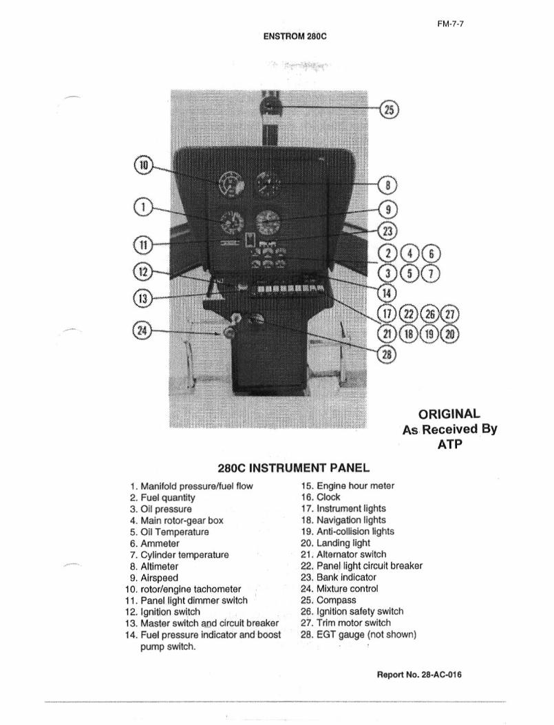
FM´•7-7
ENSTROM ?BOC
25
1 9
n 000266
11 3 8 7
n)(z2f(26f(n
28
ORIGINAL
As Received ByATP
280C INSTRUMENT PANEL
1. Manifold pressure/fuel flow 15. Engine hour meter
2. Fuel quantity 16. Clock
3. Oil pressure 17. Instrument lights4. Main rotor-gear box 18. Navigation lights5. Oil Temperature 19. Anti-collision lights6. Ammeler 20. Landing light7. Cylinder temperature 21. Alternator switch
8. Altimeter 22. Panel light circuit breaker
9. Airspeed 23. Bank indicator
in. rotor/engine tachometer 24. Mixture control
11. Panel light dimmer switch 25. Compass12. Ignition switch 26. ignition safety switch
13. Master switch and circuit breaker 27. Trim motor switch
14. Fuel pressure indicator and boost 28. EGT gauge (not shown)
pump switch.
Repan No. 28-ACa16

FM-7-8
IERISTROM 280C
Electrical Power Panel. The following switches/combination cir-
cuit breakers are located on the switch circuit breaker panelmounted on the instrument console within easy reach of pilot or
co-pilot: magneto key switch, master switch, alternator switch
and alternator circuit breaker, boost pump switch, navigationposition lights switch, anti-collision strobe light switch, landinglight switches, panel light switch, starter switch, and trim motor
switch.
LIGHTING EQUIPMENT
The helicopter lighting;lkjt inc’ludes the relquired lights necessaryfor VFR night operatibn plus additional lighting equipment for
utility and convenience The electrical panel on the
right-hand side of the instrument console ~ontains the protectivecircuit breakers and control panels for the li~hting equipment.
Position Lights. Two position lights are located one on each
horizontal stabilizer tip and one light is located aft of and below
the tail rotor gearbox.
Anti-Collision Lights. The anti-collision lights have a strobe
flashing action that provides for adequate identification of the
helicopter. They are operated by the anti-collision switch located
on the panel.
Landing Lights. The landing lights are of the permanent extend
type, one is mounted on the nose and the other one the under-
side of the aircraft and set in the desired angle for the best for-
ward and down illumination. The switches for operation of the
landing lights are located on the instrument panel in the electri-
cal console section. The light on the underside of the aircraft is
primarily designed to provide illumination while hovering.
GROUND HANDLING VI~HEELS
Each landing gear skid:tube has a manuallyloperated over-cen-
tering device to lower the wheels or retract them for flight. The
ground handling wheels should be retracted and the helicopterallowed to rest on the skids when engine run-up is being per-formed or when helicopter is parked.
Report No. 28-AC-016

FM-7-9
ENSTROM 2800
BAGGAGE COMPARTMENT’!I: ´•-:ly;
The compartment for storage of baggage is provided in the area
aft of the engine compaltment. Access is through a single door
located on the right-hand side which has a lock for external lock-
ing. The capacity of the compartment if approximately 10 cu. ft.
and has an allowable loading capacity of 60 ibs. at Station 135.
SHUI
ORIGINALAs Received BY
ATP
R~pOn NO. 28-AC-016

FM-8-1
ENsIROM 280C
SECTION 8 AIRCRAIFTWANDLING,SERVICING AND MAIN~TENANCEIf you wish to obtain maximum performance and dependabilityfrom your 280C Helicapt~r, certain inspection and maintenance
requirements must be followed. It is always wise to follow a
planned schedule of lubrication and maintenance based on the
climatic and flying conditions encountered in your locality. Keepin touch with your Enstrom dealer and take advantage of his
knowledge and experience. Your dealer is ready and willing to
assist you and to keep you abreast of all changes, whether it be
maintenance or periodic servicing of the helicopter.
GROUND HANDLING
To lower the ground handling/;wh~el_s,l insert the slotted handle
facing forward. While applying ’al’:~onstant pressure to handle,release pin. Pull uarifl aft Inrith :a lifting,,.motion until the holes
line up. Insert the 19CnS pin. t(e~p firm,grip on the handle
until pin is in place.
CAUTION: 1. Keep yi~ur feet from under the skids.
2. Stay on outside of skid, dlo not straddle.
MOORING
Although it is not generally necessary to tie down the helicopter,a nylon rope can be attached to the landing gear cross tube at
the oleo attach points. One blade should be placed parallel to
tail cone and tied to tail cone.
TRANSPORTING
If transporting helicoptBr on trailer or truck, skids may be
secured to bed of trailer allowing oleo’s to function.
a. Remove three main rotor blades and store in blade box.
b. Secure tail rotor.
c. Disconnect battery.
STORAGE
The metal-fiberglass construction of you 280C makes outside
storage practical, although inside storage will increase its life
just as inside storage will increase, the life of your car. If your280C must remain inactive for a Zime, cleanliness is probably the
most important It:is suggt~sted that a canvas or
nylon cover be placed over the ’rotol. head. If storage is for an
extended period, see your Lycorrii?g:Manuai for preservationinformation.
Report No. 28-AC-016
FM-8-2
ENSTROM 2800
HOISTING
To lift the entire helicopter, the use of a nylon sling of approxi-mately 3,000 Ibs. capacity is required. The nylon sling is placedaround each grip assembly.
JACKING
It is possible to jack up the helicopter inboard of upper oleo
attach points on forward and aft cross tubes.
CAUTION: Support the tail cane at extreme end.
EXTERIOR PAINT
The finish of your helicopter should be kept clean. It requires no
special care. When washed, however, water should not be
Sprayed directly into any bearings. Any good grade of car wax
will help to maintain the condition of the factory finish. It is very
important that the main rotor blades be kept clean and free of
dirt. After all, the blades are an airfoil, and to get maximum lift,
they must be clean.
WINDOWS AND DOORS
The windows and doors are made from a fine grade of acrylicplastic. These surfaces can be scratched if dirt, bugs or other
foreign material are not removed promptly. If the windshield is
excessively dirty, a water and mild soap solution will help lift the
dirt.
CAUTION: Never take a rag to wipe dirt from the glass areas
on your helicopter. There are many good productsmade especially for the cleaning of acrylic plasticsurfaces
UPHOLSTERY AND CARPETS
No special care is required to keep the interior of your helicopterclean. A good stiff broom will help remove the imbedded dirt;vacuum the interior whenever possible. Any good upholsterycleaner can be used on the carpets and seats, but a word of
caution when cleaning the seat belts. They are nylon, and cer-
tain cleaning agents will destroy the material used in their con-
struction.
LANDING GEAR SHOCK STRUTS
The oleo struts are of the air-oil type and require little mainte-
nance. It is suggested that the oleo be wiped off frequently to
keep the abrasive action of dirt and oil to a minimum.
Report No. 28-AC-018

FM-8-3
ENSTRoM 280C
AIR CLEANER OR FILTER
The air cleaner is an important part of your engine’s induction
system. If it becomes dirty or clogged, your engine will use more
fuel and will not produce maximum power. Excessively dirty fil-
ters will allow particles of dirt to be sucked into the cylinders,causing major damage. If your helicopter is operated in any
dusty and high grass areas, check the air filter more frequently.
LIGHTS
Check the electrical system of the helicopter daily and alwaysbefore night flying is planned. Keep the light lens clean for maxi-
mum brilliance.
BATTERY
The battery will normally require only routing maintenance.
However, if you should operate in a warm climate, an occasional
check for fluid level is recommended. Keep the battery terminals
and battery compartment free of corrosion.
DAMPERS-MAIN ROTOR
To check for lead-lag operation, raise the blade off its droop stopand move each blade fore and aft by gripping blade at tip. A
resistance indicates damper operation. There should be no
undamped motion.
TRANSMISSION-MAIN
The transmission requires no special attention other than check-
ing the sight gauge on the rear of the transmission on the right-hand side.
TRANSMISSION-TAIL ROTOR
The transmission requires no special attention other than check-
ing the oil level by sight gauge.
LUBRICATION
Lubrication information is included in the Maintenance Manual. It
is imperative that the correct lubricants be used and trained per-sonnel do this job properly. Each item should be serviced at pre-scribed intervals. At the same time, all other items requiringmore frequent service should receive attention. The intervals
stated on the lubrication diagram should be considered maxi-
mum for average service. If your helicopter is operated under
abnormal conditions, check these items more frequently.
Report No. 28-Ac-016
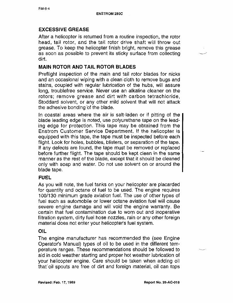
FM-8-4
ENSTROM 2800
EXCESSIVE GREASE
After a helicopter is returned from a routine inspection, the rotor
head, tail rotor, and the tail rotor drive shaft will throw out
grease. To keep the helicopter finish bright, remove this greaseas soon as possible to preveiit its sticky surface from collectingdirt.
MAIN ROTOR AND TAIL ROTOR BLADES
Preflight inspection of fhe main, and tail rotor blades for nicks
and an occasional wiping with a clean cloth to remove bugs and
stains, coupled with regular lubrication of the hubs, will assure
long, troublefree service. Never use an alkaiine cleaner on the
rotors; remove grease and dirt with carbon tetrachloride,Stoddard solvent, or any other mild solvent that will not attack
the adhesive bonding ’of the blade.
In coastal areas where the air is salt-laden or if pitting of the
blade leading edge is noted, use polyurethane tape on the lead-
ing edge for protection. This tape may be obtained from the
Enstrom Customer Service Department. If the helicopter is
equipped with this tape, the tape must be inspected before each
flight. Look for holes, bubbles, blisters, or separation of the tape.If any defects are found, the tape must be removed or replacedbefore further flight. The tape should be kept clean in the same
manner as the rest of the blade, except that it should be cleaned
only with soap an’d water. Do not use solvent on or around the
blade tape.
FUEL
As you will note, the fuel tanks on your helicopter are placardedfor quantity and octane of fuel to be used. The engine requires100/130 minimum grade aviation fuel. The use of other types of
fuel such as automobile or lower octane aviation fuel will cause
severe engine damage and will void the engine warranty. Be
certain that fuel contamination due to worn out and inoperativefiltration system, dirty fuel hose nozzles, rain or any other foreignmaterial does not enter your helicopter’s fuel system.
OIL
The engine manufacturer has recommended the (see EngineOperator’s Manual) types of oil to be used in the different tem-
perature ranges. These recommendations should be followed to
aid in cold weather starting and proper hot weather lubrication of
your helicopter engine. Care should be taken when adding oil
that’oil spouts are free of dirt and foreign material, oil can tops
Revised: Feb. 17, 1989 Report No. 28-AC-016

FM-8-5
ENSTRoM 280C
are clean before insialling~i’j when removing oil filler
cap, dirt does not enter the oil sump. When installing the engineoil filler cap, check it for security and cleanliness.
COOLING SYSTEM
If unusually high oil temperature is encountered, remove oil
cooler shroud and check for foreign matter.
REQUIRED F.A.A. FORMS
Miscellaneous data, information, and licenses are a part of the
aircraft file. The following is a checklist for that file. In addition, a
periodic check should be made of the latest Federal Aviation
Agency Regulations to assure that all data requirements are
met.
A. To be carried in the helicopter at all times.
1. Aircraft Airworthiness Certificate Form ACA 1362
2. Aircraft Registration Certificate Fore ACA 500A
3. Aircraft Radio Station License4. Weight and Balance Report5. Aircraft Equipment List
6. Flight Manual
B. Since the regulations of other national may require other
documents and data, owners of exported aircraft should
check with their own aviation officials to determine their
individual requirements.
C. Inspection Periods: FAA Regulations require that all aircraft
have a periodic (annual) inspection as provided by the
administration, and performed by a person designated bythe administration. In addition, 100-hour inspections by an
"appropriately rated mechanic" are required if the aircraft is
flown for hire. The manufacturer recommends the 100-hour
inspection for your helicopter. A copy of the sample inspec-tion forms, including the 50, 100, periodic and lubrication
guides are included in the Maintenance Manual.
Report No. 28-AC-018

FM-8-6
ENSTROM 280C
PREFLIGHT INSPECTION
After familiarizing yourself with the equipment of your 280C the
primary concern will be its operation.This checklist is designed to be used as a reference guide while
performing the preflight inspection. Detailed information is found
in the Handbook of MaintenBnGe Instructions. Thoroughly famil-
iarize yourself with this Manual before utilizing this checklist.
Prior to starting the complete:preflight inspection, check the fol-
lowing items in the cockpit: master switch OFF, magneto switch
OFF, ail other switches OFF, fuel valve ON.
EXTERIOR
CAUTION: Remove all covers and locking devices.
1. Check left hand door for securit3.2. Check windshield for cracks.
3. Check pitot tube for obstructions.4. Check landing lights for operation and security.5. Check induction intake scoop for obstructions.
6. Check right hand shock strut piston extension should be
3~" fO 13/41( from red line struts clean.
7. Check right hand landing gear for security. (Ground handlingwheels secured.)
8. Check right hand door for security.9. Drain fuel pump.
10. Check right hand engine compartment.11. Check induction hose clamps on the air filter and fuel in-
jector for security.12. Check air intake scoop for obstructions.
13. Check right hand fuel tank FULL 100/130 octane capsecured. Drain tank sump.
14. Check main gear box oil level.
15. Check baggage door locked.16. Check right hand static port-opening unobstructed.
17. Check tail cone for general condition.
18. Check tail rotor drive shaft for security.19. Check navigation and strobe lights for operation and
secu rity.20. Check stabilizer for security.21. Check tail rotor pitch links for binding or looseness.
Check tail rotor blade for security and leading edge for
nicks, bonding separation and general security.Check tail rotor teeter stop to insure rubber bumpers are
intact.
Check tail rotor strike tabs for security and damage.
Report No. 28-AC-016

FM-8-7
ENSTROM 280%
22. Check tail rotor guard for damage ana secunty.
23. Check left hand static port-opening unobstructed.
24. Check main rotor blades for nicks, bonding separation or Ilooseness. If blade tape is installed, inspect tape for holes,bubbles, blisters, separation or lifting.
25. Check main rotor pitch links for binding or looseness.
26. Check cyclic and collective walkihg beams for security.
27. Check blade dampers for proper security and oil level.
28. Check left hand fuel tank FULL 100/130 octane
cap secured, drain tank sump.
29. Check engine oil 6 quarts minimum, 8 quarts maximum.
30. Check fuel system for leaks.
31. Check exhaust manifold for cracks and looseness.
32. Check engine for oil leaks.
33. Check turbocharger’ exhaust inlet and outlet clamps for
secu rity.
34. Check turbocharger air inlet clamps for security.
35. Check turbocharger oil lines for leaks.
36. Check turbocharger mount bracket for security.
37. Check belt drive system.
38. Check left hand shock struts piston extension should be
3~1" to 13/411 from red line struts clean.
39. Check left hand landing gear for security. (Ground handlingwheels secure.)
40. Check operation of all lighting for night flight.
INTERIOR
1. Check and adjust tail rotor pedals.
2. Check seat belts fastened.
3. Doors latched.
4. Collective full down and friction on.
5. Check clutch disengaged.
6. Check throttle CLOSED.
7. Check mixture IDLE CUT OFF.
8. Check fuel valve ON.
Revised: Feb. 17, 1989 Report No. 28-AC-016

FM-8-8
ENSTROM 2802
9. Check magneto switch OFF.
10. Radio switches OFF.
11. Set master switch ON.
12. Check fuel quantity.13. Check fuel pressure warning light (press to test).14. Check trim motors for operation.
15. Check controls for freedom of operation.
16. Set altimeter.
Revised: Feb. 17, 1989 Report No. 28-AC-016
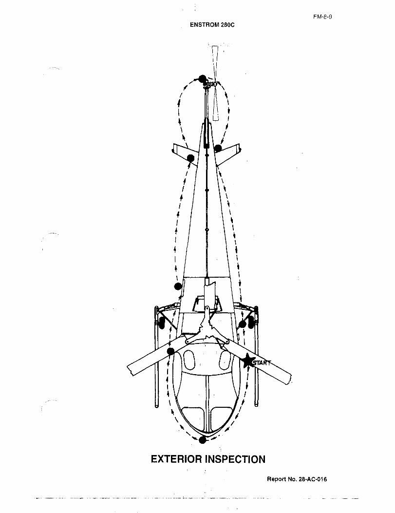
FM-8-9
ENSTROM 280C
f ~P"X‘\IPII ,I
I ,iu
4~ IU\ j
I II I
I
I
s I i
i 1 8
IIY1~
rl A
fY I-
o
lv VIII /e
EXTERIOR INSPECTION
Report No. 28-AC-016

FM-4-~
ENSTROM 280C
SECTION 9 OPERATIONAL INFORMATION
The operating data and information contained herein is not
intended to provide flight instructions, but to present a verbal
picture of the helicopter handling qualities and control applica-tion through the various phases of the flight regime. Also dis-
cussed are flight characteristics which are common to most heli-
copters, and the special features pertinent to the Model 280C
helicopter.
SOLO FLIGHT
Solo flight is permitted from the left side only.
TAXIING
Taxiing, as literally interpreted, is not possible as the helicopteris equipped with skid-type landing gear. Movement of the heli-
copter from one ground position to another can be accomplishedby ground personnel, when the rotors are not turning, with the
use of quickly installed ground handling wheels or by the pilotflying the helicopter from one location to another at an altitude in
close proximity to the ground surtace.
TAKEOFF TYPE QF: TAKEOFF
The known factors which must be considered prior to take-off
include gross weight, temperature, density altitude, and the area
from which operations are to be conducted. With this knowledgeai7d the ability of the Model 280C to operate from either pre-pared or unprepared areas and surfacesi the type of take-off
can be easily determined.
NORMAL TAKEOFF TO MOVER
A normal lift-off to a hovering altitude within ground effect is the
most common fype of takebff and should be used whenever
possible. Normal lift-off c~n be accomp(ishea at moderate alti-
tudes and at average operating gross weights. In this type of
takeoff, the safety factor is high because the helicopter is lifted
from the ground vertically to height of 3 to 5 feet where the flight Icontrols and engine may be checked for normal operationbefore starting a forward speed climb. A normal takeoff is made
in the following manner:
a. Increase throttle to 2900 RPM, with the collective pitch full
down.
b. Place cleric control: in the neutral position or to a positionwhich places rotor plane paraliell,to horizontal if helicopter is
sitting on a slope.
Report No. 28dC-D1~

FM-9-2
ENSTROM 2806
c. Increase collective pitch control slow~y and smoothly until a
hovering altitude of 3 to 5 feet is oi;tained, applying anti-
torque pedal to maintain heading as collective pitch is
increased.
d. As the helicopte~r breaks ground, minolr corrections of the
cyclic control may b~ required to insure vertical ascent, and
directional heading maintained by the use of the appropriateanti-torque control pedal.
NORMAL TAKEOFF FROM MOVER
Hover briefly to determine’ and insure th~t the engine and flightcontrols are operating properly. From a nor~nal; hover 8ltitude of
3 to 5 feet, apply forward ~yclic stick to accelerate smoothly into
effective translational lift. M’aintain hovering altitude with an
application of collective pitch until translational lift has been
obtained and the ascent has begun. Then slowly lower nose of
Ihelicopter to an attitude that will produce an increase of airspeedto best climb speed. Adjust controls and power as required to
establish the desired rate of climb.
MAXIMUM POWER TAKEOFF
Hover helicopter to 3 to 5 feet altitude 2900 RPM. Apply for-
ward cyclic smoothly. As forward motion increases, apply collec-
tive and throttle until 36.5 inches of manifold pressure is attained
at 2900 engine RPM. Do not exceed 36.5 inches of manifold
pressure during the takeoff maneuver. Do not increase collective
pitch beyond this point Coverpitching) as this will cause engineand rotor RPM to decrease.
CAUTION: Ail "C" models are equipped with a full-time turbo-
charger and an overboost warning light on the
instrument panel to warn the pilot of an overboost
condition. Transient overboost conditions which
may trigger the caution light may not show as over-
boost condition on the MAP indicator. The MAP
indicator red line is the determining factor in ascer-
taining the magnitude of an overboost condition
and must be logged in the engine log and inspec-tions performed per Lycoming Bulletin 369F.
Maintain 3 to 5 feet altitude by the use of cyclic control. As trans-
lational lift speed is reached (15-20 MPH), apply aft cyclic to
seek climb angle that will allow the helicopter to climb and accel-
erate to the best rate of climb speed. Maintain heading duringtakeoff by coordinate use of directional control pedals and cyclic.
Revised: Report No. 28-AC-016

FM-9-3
ENSTROM 280C
MAxlMunn AREAS
Conditions may occur in which the helicopter must be operatedfrom confined areas in which take-off distances (from hover to
best rate of climb speed) are not sufficient to clear obstacles that
may be in the flight path (trees, buildings, wires, etc.). In order to
clear such obstacles safely, the climb portion of the take-off
must utilize the best angle of climb airspeed (30 MPH safe side
of height velocity curve). This angle of climb will substantiallyshorten the distance required to clear obstacles. To accomplishthis type of take-off, hover helicopter at 3 to 5 feet altitude and
2900 RPM. Apply forward cyclic smoothly. As the helicopterbegins to accelerate forward, apply collective and throttle until
RPM. (See preceding caution note). Do not increase collectiveI36.5 inches of manifold pressure is obtained at 2900 engine
beyond this point (overpitching) as this will cause engine and
rotor RPM to decrease. Maintain 3 to 5 feet altitude by use of
cyclic control. As translational speed is reached (15-20 MPH)apply aft cyclic to seek climb anglethat will maintain 30-35 MPH
(refer to height-velocity diagram in flight manual). After clearingall obstacles at this airspeed, apply forward cyclic and readjustcollective and throttle as desired for further flight.
NOTE: If RPM is lost due to overpitching, it may be regained Iby maintaining 36.5 inches of manifold pressure, tower-
ing collective slightly and applying some aft cyclic.
In both preceding conditions it is imperative that the
helicopter has accelerated a little beyond translational
speed in order to accomplish these maneuvers.
Therefore, good judgement must be used to determine
the rate at which the helicopter is accelerated from
hover to translational speed and to determine if suffi-
cient distance is available to clear obstacles under the
existing density altitude conditions.
Crosswind Takeoff. In the event a crosswind takeoff is
required, normal takeoff procedures are to be followed.
However, as the helicopter leaves the ground, there will be defi-
nite tendency to drift downwind at a rate proportionate to the
wind velocity. This tendency can be corrected by moving and
holding the cyclic stick sufficiently in the direction of the wind to
prevent downwind drift. During crosswind takeoff, it is advisable
to keep open areas to windward,side of flight path to facilitate
emergency landing if it should be necessary.
Revised: Report No. 28-AC-016
FM-9-4
ENSTROM 280C
NORMAL APPROACH FOR LANDING
The object of a normal approach is to fly the helicopter to a
hover over the selected spot prior to touchdown. To accomplishthis objective, the cruise airspeed is decreased gradually to 58
MPH and engine speed is maintained at 2900 RPM. Control rate
of descent with collective and throttle (manifold pressure); air-
speed with cyclic control. As the selected landing area is
approached, the airspeed and rate of descent are decreased
until a zero ground speed hovering altitude is attained at approx-imately 3 to 5 feet altitude.
STEEP APPROACH
Steep approach procedure requires a precision power control
approach and is used to clear obstacles in the flight path when
accomplishing a landing in a confined area. The airspeed in a
steep approach should be 30 to 35 MPH (safe side of H/V
curve) and the rate of descent should be as low as possible for
the desired angle of descent. Since a relatively high amount of
power will be required to control the rate of descent, a minimum
amount of additional power will be required to accomplish a
hover. The aiming point to spot of intended hover in groundeffect should be as near as possible after clearing final obsta-
cles. This will allow an over-run to get helicopter stopped in case
power setting should occur during slowdown from 30 MPH down
to O airspeed. During descent, the airspeed is controlled byappropriate cyclic stick application and the rate of descent is
controlled by proper application of collective pitch and throttle. In
the final stages of appro.ach, the collective pitch is increased
gradually as the cyclic stick is adjusted to reduce the airspeedfrom 30 to 35 MPH to O groundspeed. This should be accom-
plished in a way which will reduce the; rate of descent and
groundspeed to zero the moment the hovering altitude is
reached.
LANDING-LANDING SITE EVALUATION
The versatility of the helicopter permits safe operation from unfa-
miliar and unprepared sites, such as open fields, mountainknells and ridges, beaches, snow, and iced areas. Any selected
landing site in the afore-mentioned areas must be properly eval-
uated and the pilot must use proper techniques to effect land-
ings and takeoffs from these sites. Although the helicopter is
designed for and is capable of operation from restricted areas,the final analysis of the situation on the decision to land must be
determined by the best professional judgement of the pilot. Prior
to attempting operation of the helicopter from unprepared areas,
FAA Approval: April 20, 1978
Revised: Feb. 17, 1989 Report No. 28-AC-016

FM-9-5
ENSTROM 280C
the pilot must and evaluate by a
low speed pass into the wind over the intended landing site.
Generally, the landing site should be near level, and dependingon existing density, altitude and gross weight conditions, should
meet the obstacle clearance requirements set forth in this
Manual. The pilot must also consider personal proficiency, wind
and terrain roughness when evaluating the suitability of the land-
ing area.
WIND DIRECTION AND VELOCITY
The effects of wind on takeoff’ and landings are important factors
and should be considered in the operation of the helicopter;however, in planning critical helicopter operations, the effects of
winds can be relied upon to´•assist in accomplishing landingsand takeoffs from unobstructed areas. If the helicopter were rid-
ing a gust of wind on the final approach and the gust should
decrease as the helicopter was approaching a hover, the heti-
copter would probably rapidly "Settle" if the wind factor was
planned on to execute the landing. This dondition will also hold
true during the initial´•lphase of takeoff. If an operation is depen-dent on wind conditions, all Oth~r conditions being marginal, the
helicopter gross weight should be reduced. When lan~ing area
is determined to be marginal, the pilot, exercising good judg-ment, should select another´•site. Another effect of wind that
must be considered is the "lee" effect of the wind over hills,ridges, and obstacles. The downdrafts resulting from these con-
ditions particularly affect the initial phase of takeoff or final
phase of landing.NORMAL LANDING
After completion of the normal approach to a hover altitude,maintain engine RPM and decrease collective pitch sufficientlyto affect a constant, smooth rate of descent until touchdown.
During final descent, make necessary corrections with direction-
al pedals and cyclic control to mdintain a level attitude and con-
stant heading to minimize movement on ground contact. After
ground contact, continue to decrease collective pitch smoothlyand steadily until the entire weight of the helicopter is groundsupported and then decrease collective pitch to minimum.
CROSSWIND LANDING
Crosswind landings generally can be avoided in helicopter oper-ations. Occasionally, when operating from unprepared areas,such as plowed or furrowed fields, ridges and upslope or down-
slope surfaces, necessity may require that crosswind landingsbe performed. When conditions demand and terrain features
Revised: Report No. 28-AC-016
FM-9-6
ENSTROM 280C
dictate, a crosswind landing´•is also utilized to preclude the nec-
essary of landing on a high, tilting angle or a dangerous tail lowaltitude. Prior to accomplishing the crosswjnd landing, the pilotshould evaluate the climatic co’nditions, including wind velocityand the terrain, and then eroceed as follows: Engine RPM maxi-
mum, approach landing spotfrom crosswind direction if possi-ble, and hover. Hold cyclic control into direction of wind to pre-vent side drift, and reduce collective pitch and, descend as in
normal landing.
FLIGHT CHARACTERISTICS HANDLING AND STABILITY
The flight characteristics of this helicopter in general are similar
to other single rotor helicopters. The particularly noticeable dif-ference is the handling ease and additional stability that is evi-
dent during takeoff, hovering, and all modes of flight. To obtain
or increase helicopter forward speed, simultaneously apply for-
ward control stick and increase main rotor pitch, and maintain
power through constant flight condition. Altitude is maintained
through-out the entire range of forward and rearward flightspeeds by fore and aft movement of the cyclic control stick in
coordination with collective pitch application. Directional headingis controlled by the application of lateral cyclic control and
appropriate directional control pedal. Blade stall can only occur
during flight and is caused by high angle attack on the retreatingblade and occurs at the inboard section of the blade area. This
condition cannot be encountered when the helicopter is operat-ed within the specified operating limits as stated in the FlightManual. Blade stall is the result of numerous contributing factors
such as gross weight, low rotor RPM, airspeed acceleration and
altitude. The condition is most likely to occur at higher airspeedsand low operating RPM; it also follows that the condition will
occur sooner with high values of altitude, gross weight, and
angle of bank. The major warnings of approaching retreatingblades stall conditions in the order in which they will generally be
experienced are:
1. Abnormal 3 per revolution vibration.
2. Pitchup of the nose.
3. Tendency for the helicopter to roll in the direction of thestalled (left) side.
At the onset of blade stall vibration, the pilot should take the fol-
lowing corrective measures:
1. Reduce collective pitch.
2. Increase rotor RPM.
Revised: Report No. 28-AC-016

FM-9-7
ENSTRoM a80C
3. Reduce forward
4. Descend to lower altitude.
5. Minimize maneuvering.MANEUVERING FLIGHT
Movement and response of the flight controls while conductingflight maneuvers is normal at all times when the helicopter is
operating within the limitations set forth in the Flight Manual.
Throughout the entire realm of flight, it will definitely be noted
that minimum effort is required by the pilot for control of move-
ment, and by use of trim system, a near zero control force effect
effort is required, regardless of the gross weight or CG location.
HOVERING FLIGHT
The hovering capabilities df the Model 280C Helicopter for both
in and out of ground effect hovering will allow flight operations to
be excellent.
It should be remembered, however, th~t the performance of all
helicopters is affected by numerous factors such as climatic con-
ditions, altitude, temperature, and gross weight. It is a known
fact that "in ground effect" hovering performance is better than
"out of ground effect" performance for reasdn of the helicopterbeing in part supported by a cushion of air being provided by the
rotor downwash when the helicopter is in close proximity to the
ground. Additional performance will also be realized when oper-
ating at low temperatures, which is the equivalent of atmospher-ic density, and wind, which represents airspeed. Either of these
conditions or a combination of both increases performance since
low temperatures allow the engine and rotor to provide more lift
and wind reduces the power required.
STUDENT TRAINING
Autorotation practice should be carried out over terrain suitable
for full autorotational landing in case of inadvertent engine stop-page. Sudden power cuts to idle position are not recommended
since the fuel injector is quite sensitive to improper adjustmentof idle mixture, idle rpm and sudden power reduction.
CAUTION: Rapid throttle movement during practice autorota-
tion may decrease the life of the over-runningclutch.
NOISE ABATEMENT
Increased emphasis on improving the quality of our environment
requires renewed effort on th~ part of all pilots to minimize the
effect of aircraft;noise on the public.
Revised: Report No. 28-AC-018
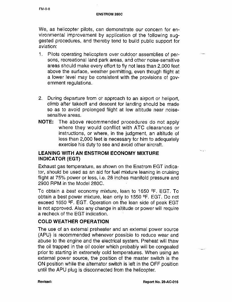
FM-9-8
ENSTROM 280C
We, as helicopter pilots, can demonstrate our concern for en-
vironmental improvement by application of the following sug-gested procedures, and thereby tend to build public support foraviation:
1. Pilots operating helicopters over outdoor assemblies of per-sons, recreational land park areas, ah~ other noise-sensitive
areas should make every effort to fly not less than 2,000 feetabove the surface, weather permitting, even though flight at
a lower level may be consistent with the provisions of gov-ernment regulations.
2. During departure from or approach to an airport or heliport,climb after takeoff and descent for landing should be made
so as to avoid prolonged flight at low altitude near noise-sensitive areas.
NOTE: The above recommended procedures do not applywhere they would conflict with ATC clearances or
instructions, or where, in the judgment, an altitude of
less than 2,000 feet is necessary for him to adequatelyexercise his duty to see and avoid other aircraft.
LEANING WITH AN ENSTROM ECONOMY MIXTURE
INDICATOR (EGT)
Exhaust gas temperature, as shown on the Enstrom EGT indica-
tor, should be used as an aid for fuel mixture leaning in cruisingflight at 75% power or less, i.e. 28 inches manifold pressure and
2900 RPM in the Model 280C.
To obtain a best economy mixture, lean to 1650 "F. EGT. To
obtain a best power mixture, lean only to 1550 "F. EGT. Do not
exceed 1650 gF. EGT. Operation on the lean side of peak EGT
is not approved. Also any change in altitude or power will requirea recheck of the EGT indication.
COLD WEATHER OPERATION
The use of an external preheater and an external power source
(APU) is recommended whenever possible to reduce wear and
abuse to the engine and the electrical system. Preheat will thaw
the oil trapped in the oil cooler which probably will be congealedprior to starting in extremely cold temperatures. When using an
external power source, the position of the master switch is the
ON position while the alternator switch is left in the OFF positionuntil the APU plug is disconnected from the helicopter.
Revised: Report No. 28-AC-016
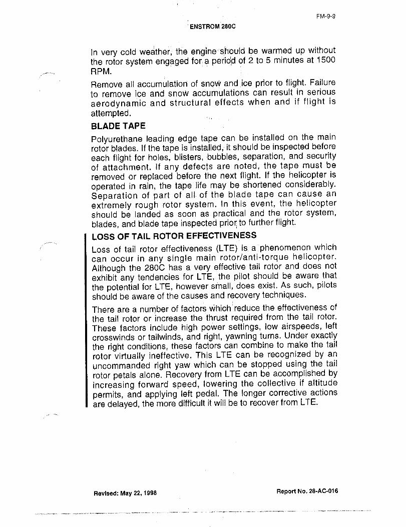
FM-9-9
ENsTRoM 2800
In very cold weather, the engine:isf7D´•uld it?e warmed up without
the rotor system engaged for a of 2 to 5 minutes at 1500
RPM.
Remove all accumulation of snow and ice prior to flight. Failure
to remove ice and snow accumulations can result in serious
aerodynamic and structural effects when and if flight is
attemptedBLADE TAPE
Polyurethane leading edge tape can be installed on the main
rotor blades. If the tape is installed, it should be inspected before
each flight for holes, blisters,;bubbles, separation, and securityof attachment. If any defects are noted, the tape must be
removed or replaced before the next flight. If the helicopter is
operated in rain, the tape life may be shortened considerably.
Separation of part of all´•of the blade tape can cause an
extremely rough rotor system. In this event, the helicoptershould be landed as soon as practical and the rotor system,
blades, and blade tape inspected prior; to further flight.
LOSS OF TAIL ROTOR EFFECTIVENESS
Loss of tail rotor effectiveness (LTE) is a phenomenon which
can occur in any single main rotor/anti-torque helicopter.
Although the 280C has a very effective tail rotor and does not
exhibit any tendencies for LTE, the pilot should be aware that
the potential for LTE, however small, does exist. As such, pilotsshould be aware of the causes and recovery techniques.
There are a number Of factors which reduce the effectiveness of
the tail rotor or increase the thrust required from the tail rotor.
These factors include high power settings, low airspeeds, left
crosswinds or tailwinds, and right, yawning turns. Under exactlythe right conditions, these factors can combine to make the tail
rotor virtually ineffective. This LTE can be recognized by an
uncommanded right yaw which can be stopped using the tail
rotor petals alone. Recovery from LTE can be accomplished by
increasing forward speed, lowering the collective if altitude
permits, and applying left pedal. The longer corrective actions
are delayed, the more difficult it will be to recover from LTE.
Revised: May 22, 1998 Report No. 28-AC-0~6
´•--I´•--´•-´•^´•´•;;-----´•-´•´•-´•´•

FM-9-10
ENSTROM 280C
FUEL FLOW VS. NOZZLE PRESSURE
Lycoming Model H101360-EIAD
With
Bendix RSA´•SABI Injector
180
f 60 i I I I _I
140
120
-1 100
g80
60
40
20
0 4 8 12 16 20 24
Nozzle Pressure Psi
Revised: Report No. 28-AC-016

FM-9-11
ENSTRoM 280C
AVERAGE CRUISE P’E#FORMANCE 2900 R.P.M.
EXTENDED RANGE AND RICH MIXTURE
180 LBS. AND 240 LBS. FUEL [NO RESERVE]G.W. 2200 LBS, SEA LEVEL D.A.
(ENDURANCE (RANGEE.G.T. NbZr. HOURS) STATUTE MI.I
tAS P.P.H. P.P.H.ILEAN P.S.I. 246 )b* 180 I~n. 2401br’1801b~.IM.P. XH.P. MPH RICH LEANIRICH R.-L. R.-L. R.-L. R.-L. R.-L.
20 51 61 63 54 !650 4 -2.8 3.5-4.4’2.6-3.3 2132681158-2011425
n 5) 72 )8 81 B -3.213.(-3.912.3-2.8 n,~8(1166´•20924 63 82 86 61 1650 6 -3.8128-3.612.1-2.7 1229´•295 1 172-222
1475
26 68 88 91 75 1650 7.2-4,6 12.5-3~2 11.9-2.4 122C281I 167´•2111500
28 75 101 102 82 1650 8.3-5.4 2.3-2.9) 1.8-2.2 232´•295 182´•212
3D 80 105 100 94 8.~-1.2 2.~-2.511.6-1.9 1211-2621)68-19932 88 107 116 NA 10.6 2.1 1 1.5 225 1166
1535
34 92 109 123 NA ~Is 1.9 1 ’’4 207 1~591550
36.5 100 112 135 NA )13.8 1.8 (1.3 201 11481550
DEFINITION OF ABBREVIATIONS
M.P. Manifold pressure inches of mercury.%H.P. Percent of rated brake horsepower.TAX MPH True airspeed miles per hour.
P.P.H. Pounds per hour fuel flow rich mixture.
RICH
P.P.H. Pounds per hour fuel flow lean mixture.
E.G.T. Exhaust gas temperature at lean mixture,LEAN also called T.I.T. turbine inlet temp.NOZZ. P.S.I. Fuel injector nozzle pressure in pounds
per square inch.
R. Rich mixture.
L. Lean mixture.
G.W. Gross Weight.D.A. Density altitude.
NA Not approved mixture SettiniJ.
FAA Approval: April 20, 1978
Revised: Feb. 17, 1989 Report No. 28-AC-016
...;~..____.; _.,_ ..._....................... ;.;....~-_._;.L.;.

FM-10-1-1
ENSTROM 280C
WET/DRY DISPERSAI, SYS’I"E~II SUPPLEMENT
NO. 1
SECTION 1 GENERAL
This supplement must be attached to the approved flight manual
when the wet/dry dispersal system is installed. Operation in
compliance with Section 2 of the Approved Flight Manual is
mandatory except as modified by this flight manual supplement.Other approved sections and supplemental data are recom-
mended procedures.
This aircraft is approved for restricted category operations when
agricultural spray equipment is installed in compliance with
Enstrom Helicopter Drawing 28-22620. (Initial installation of
electrical components, pump, clutch control, rails, drive system,boom attach fittings and upper tank attach fittings must be per-
formed by certified mechanic and entered in airframe log.) After
initial installation, removal or installation of wet/dry dispersal sys-
tem may be accomplished by owner or operator.
SECTION 2 LIMITATIONS
Airspeed Limitations: Maximum operating speed 85 MPH IAS at
S.L. power off, linear decrease to 80 MPH
IPaS at 6000 ft. HD.Altitude Limitations:
i
6000 ft. density altitude.
Weight Limitations: Maximum gross weight: 2600 Ibs.
Maximum load per dispersal tank: 350 Ibs.
Center of Gravity Forward: 96.5 in.
limitations: Rearward: 98.0
Lateral Offset
Moment: ´•3180 in-lbs. to -1855 in-tbs.
(Above 2350. Lbs.)
Type of Operation: Approved for restricted category opera-tions under provisions of FAR 137.
Placards: On Tank: "Restricted"
"Agricultural Operations Only""Max. Load Per DispersalTank- 350 Ibs.
In View of Pilot: Restricted category never
exceed speeds MPH IAS
FAA Approval: May 5, 6978 Report No. 28-AC-016
´•---I-;´•´•-´•--´•´•´•----´•---;-´•´•;--´•-´•´•´•--´• ´•´•´•´•´•^-´•--´•´•;-´•--´•--;-´•´•´•;;-´•-´•:´•1´•-´•-´•-----´•---´•´•´•---´•-´•´•;´•----´•-´•--´•-´•´•´•´•-´•´•´•´•´•----;;;´•
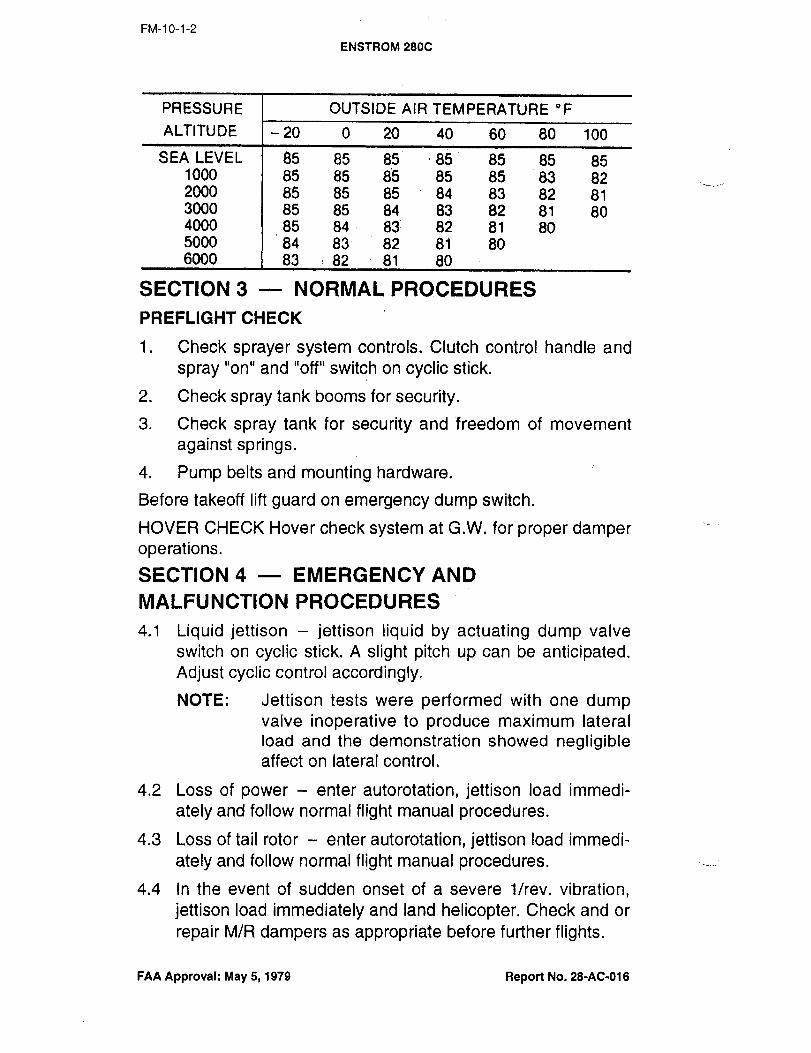
FM-10-1-2
ENSTROM 280C
PRESSURE OUTSIDE AIR TEMPERATURE ’F
ALTITUDE 20 0 20 40 60 80 100
SEA LEVEL 85 85 85 85 85 85 851000 85 85 85 85 85 83 822000 85 85 85 84 83 82 813000 85 85 84 83 82 81 804000 85 84 85 82 81 805000 84 83 82 81 806000 83 82 81 80
SECTION 3 NORMAL PROCEDURES
PREFLIGHT CHECK
1. Check sprayer system controls. Clutch control handle and
spray "on" and "off" switch on cyclic stick.
2. Check spray tank booms for security.
3. Check spray tank for security and freedom of movement
against springs.
4. Pump belts and mounting hardware.
Before takeoff lift guard on emergency dump switch.
MOVER CHECK Mover check system at G.W. for proper damperope rations.
SECTION 4 EMERGENCY AND
MALFUNCTION PROCEDURES
4.1 Liquid jettison jettison liquid by actuating dump valve
switch on cyclic stick. A slight pitch up can be anticipated.Adjust cyclic control accordingly.
NOTE: Jettison tests were performed with one dumpvalve inoperative to produce maximum lateral
load and the demonstration showed negligibleaffect on lateral control.
4.2 Loss of power enter autorotation, jettison load immedi-
ately and follow normal flight manual procedures.
4.3 Loss of tail rotor enter autorotation, jettison load immedi-
ately and follow normal flight manual procedures.
4.4 In the event of sudden onset of a severe i/rev, vibration,
jettison load immediately and land helicopter. Check and or
repair M/R dampers as appropriate before further flights.
FAA Approval: May 5, 1979 Report No. 28-AC-016

FM-10-1-3
ENS7ROM 2800
4.5 Spreader malt -i~sing cyclic displacementis required for hover´• or forward,flight, land immediately and
check loading situation and spreader operation.
SECTION 5 PERFORMANCE
Figure 5-1 Vne vs. D.A.
Figure 5-2 Hover I.G.E. curve extended to 2600 Ibs.
Figure 5-3 Airspeed calibrated vs. indicated
Figure 5-4 Height velocity diagram
FAA Approval: May 5, 1978 Report No. 28-AC-016

FM-10-1-4
ENSTROM 2800
SECTION 5 PERFORMANCE
V never exceed VS. DENSITY ALTITUDE
Vne demonstrated at 2750 engine rpm2600 Ib. gross weight
FIGURE 5-1
14000
12000
it 1Q~Oo
8~00
MAX. APPROVED %EILINGb 6~90Q
li~OQ
ER QNt~));
2000
S.L.M 4Q 80 80 100 120
Indicated Airspeed MPH
FAA Approval: May 5, 1978 Report No. 28-AC-018

FM-10-1-5
ENSTROM 280C
MOVER CEILING:i:N3’X FOOT SKID HEIGHT
WITI-;IAG. KIT
FIGURE ´•5-2
MAX. APPROVED CEILING6000
I I\
PoI Y r\ \~3
a, 4000
STANDARD DAY~, \0~6_ h
2000
MAXIMU~ IAPPROVED WEIGHT
2200 2300 2400 2500 2600
Gross Weight Lbs.
FAA Approval: ~ay 5, 1918 Report No. 28-AC-016

FM-IO-1-6
ENSTROM 2800
AIRSPEED CALIBRATION
2600 LB. GR. WT.
AG TANKS AND BOOMS
FIGURE 5-3
120
100
f
B 60
qO
20
0 20 40 60 80 100 120
Indicated Airspeed MPH
NOTE: Indicated speeds below 20 MPH are not reliable.
FAA Approval: May 5, 1978 Report No. 28-AC-018
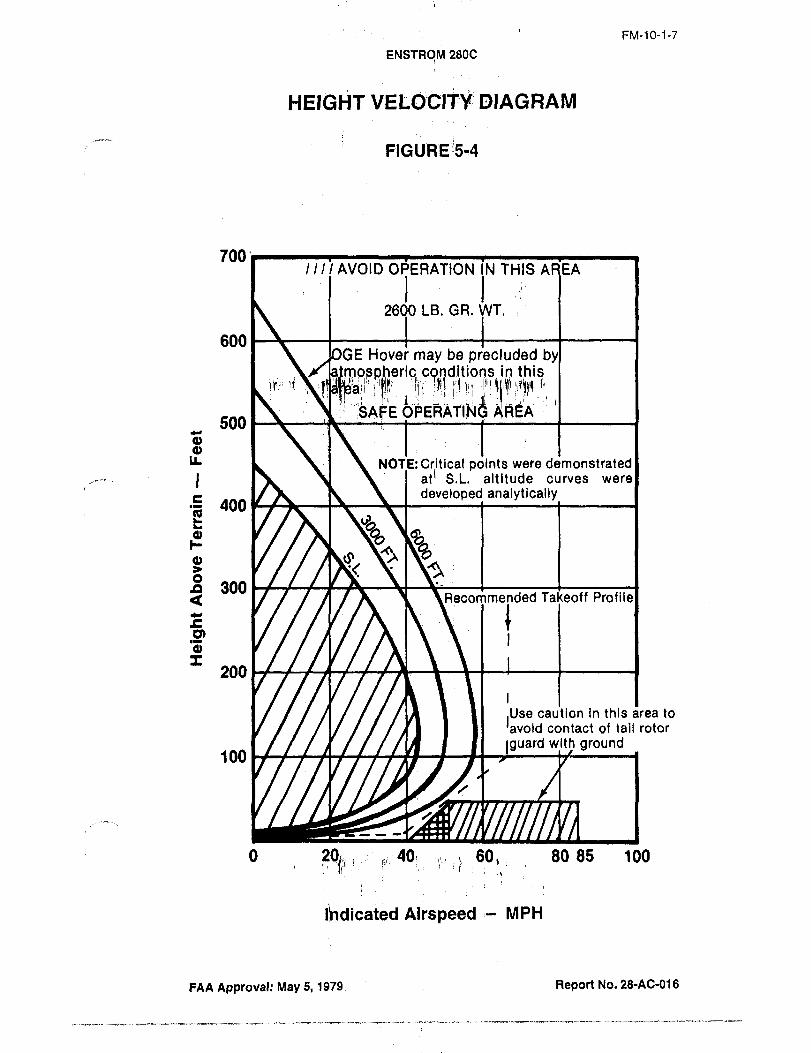
FM-10-1-7
ENSTR4rJi 2800
HEIGHT DIAGRAM
FIGURE 15-4
700’I III AVOID OPERATION IN THIS AREA
2600 LB. GR. WT.
600E Hover may be precluded b
sDheric cqrlditions in this~rri ii
id pi~iA’SA EOPERATI~N500
IL NOTE: Critical points were demonstrated,11 S.L. altitude curves were
E developed analytically400
8 300<5 Recommended Takeoff Profile
C
200
,Use caution in this area to
’avoid contact of tail rotor
guard with ground100
O 2~ ,:40: !i´•! 801 80 85 100
Ihdicated Airspeed MPH
FAA Approval: May 5, 1979; Report No. 28-AC-018

FM-1 0-1-8
ENSTRoM 280c
SECTION 6 WEIGHT AND BALANCE
Items to be used with basic Flight Manual Form No.’s F-165,F-166, F-167 and F-168 for helicopter weight and C.G.
calculations.
ITEMS WT. ARM MOMENT
Wet system removable portion 113.65 107.77 12,247.59Dry system removable portion 71.35 97.60 6,963.47Items remaining on helicopter 13.25 ~89.94 1,191.12
(Normal category)Dispersal tank load
_
’:I .95.00
SECTION 7 SYSTEM DESCRIPTION AND
INSTALLATION INSTRUCTIONS
Initial installation see Enstrom drawing 28-22620 and hand-
book "lnstallation Instructions and Parts List Combination
Wet/Dry Ag Kit 831000.
The following dispersal system items may remain on the heli-
copter for normal category operations.1. Rail assembly2. Power take-off assembly3. Strut fittings and upper tank fittings4. Pressure gage
5. Clutch control
6. Electrical harness and switches
Installation Procedures Wet Dispersal System1. Position tanks on rails and secure with (4) clevis pins (upper
and lower).NOTE: Check internal tank mounting. Isolation mount
spring should be in free state (no preload with
tank empty). Check nut should be 1.00 in. from
end of threaded rod.
2. Position wet center section on rails and secure with clevis
pins.3. Attach cross feed assembly to spray tanks, secure with over
center latch and safety wire, and install 2 hoses to center
section.
4. Attach clutch control cable.
5. Remove tape securing belt to jack strut and place belt on
power take-off.
FAA Approval: May 5, 1978 Report No. 28-AC-016

FM-10-1-9
6NSTROM 280C
6. Connect pressure and emergency dumpmotor electrical plugs.
7. Attach spray booms and safety.
8. Inspect system and perform operational check.
9. Make log book entry, wet dispersal system installed.
Helicopter approved for restricted categor/ operations only.
VVet System Removal Steps 1 through 7.
Installation Procedures Dry Dispersal System
1. Position tanks on rails and secure with (4) clevis pins.
NOTE: Check internal tank mounting. Isolation mount
spring should be in free state (no preload with
tank empty). Check nut should be 1.00 in. from
end of threaded rod.
2. Install rt. side spreader under tank and secure with over-
center latch (butterfly valve aft) and safety wire. Connect
electrical plug to valve motor.
3. Install left spreader under tank.
4. Install and adjust linkage between butterfly valves.
5. Install angle drive using 2 clevis pins and safety.6. Install "V" belt and adjust tension.
7. Install left and right take-up assemblies.
8. Install long "V" belt to each spreader (lower to rt. spreader)and adjust tension.
9. Inspect system and perform operational check.
10. Make log book entry. Dry dispersal system installed, heli-
copter approved for restricted category operations only.
Dry System Removal Reverse Steps 1-8.
To return helicopter to normal category remove wet or dry dis-
persal system per above instructions and:
1. Cap electrical plugs, fasten ends to rail or cross tube with
tape or bundle ties.
2. Fasten clutch cable to cross tube.
3. Tape "V" belt to Jack Strut.
4. Inspect Helicopter.
FAA Approval: May 5, 1978 Report No. 28-AC-016
FM-10-1-10
ENSTROM 280C
NOTE: Possible deterioration of rubber parts and corro-
sion of helicopter structure may occur when cer-
tain dispersants are used. Inspection intervals
and cleaning procedures should be modified to
prevent possible damage.5. Make log book entry, wet/dry dispersal system removed
except for allowance provisions remaining on helicopter.Helicopter approved for normal category operations.
FAA Approval: May 5, 1978 Report No. 28-AC-016
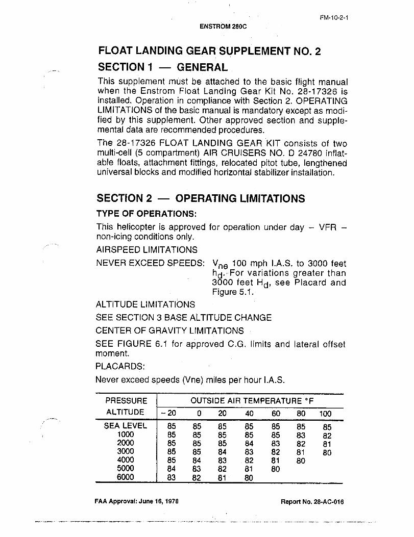
FM-10-2-1
ENsTROM 280c
FLOAT LAN DING GEAR SU PPLEMENT NO. 2
SECTION 1 GENERAL
This supplement mijst be attached: to the basic flight manualwhen the Enstrom FloatLanding Gear Kit No. 28-17326 isinstalled. Operation in compliance with Section 2. OPERATINGLIMITATIONS of the basic manual is mandatory except as modi-fied by this supplement. Other approved section and supple-mental data are recommended procedures.
The 28-17326 FLOAT LANDING GEAR KIT consists of twomulti-cell (5 compartment) AIR CRUISERS NO. D 24780 inflat-able floats, attachment fittings, relocated pitot tube, lengtheneduniversal blocks and modified horizoritai stabilizer installation.
SECTION 2 OPERATING LIMITATIONS
TYPE OF OPERATIONS:
This helicopter is approved for operation under day VFR
non-icing conditions only.AIRSPEED LIMITATIONS
NEVER EXCEED SPEEDS: V,, 100 mph I.A.S. to 3000 feet
hd.-For variations greater than3000 feet Hd, see Placard and
Figure 5.1.
ALTITUDE LIMITATIONS
SEE SECTION 3 BASE ALTITUDE CHANGE
CENTER OF GRAVITY LIMITATIONS
SEE FIGURE 6.1 for approved C.G. limits and lateral offsetmoment.
PLACARDS:
Never exceed speeds (Vne) miles per hour I.A.S.
PRESSURE OUTSIDE AIR TEMPERATURE "F
ALTITUDE i 20 0 20 40 60 80 100
SEA LEVEL 85 85 85 85 85 85 851000 85 85 85 85 85 83 822000 85 85 85 84 83 82 813000 85 85 84 83 82 81 804000 85 84 83 82 81 805000 84 83 82 81 806000 83 82 81 80
FAA Approval: June 16, 1978 Report No. 28-Ac-016
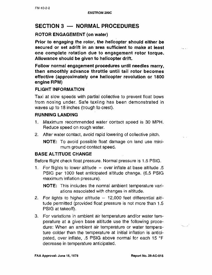
FM-1 0-2-2
ENSTROM 2806
SECTION 3 NORMAL PROCEDURES
ROTOR ENGAGEMENT ton water)
Prior to engaging the rotor, the helicopter:should either be
secured or set adrift in an’area sufficient to make at least
one complete rotation due to engagement rotor torque.Allowance should be given to helicopter drift.
Follow normal engagement procedures until needles marry,then smoothly advance throttle until tail rotor becomes
effective (approximately one helicopter revolution or 1800
engine RPM)
FLIGHT INFORMATION
Taxi at slow speeds with partial collective to prevent float bows
from nosing under. Safe taxiing has been demonstrated in
waves up to 18 inches (trbugh to crest).
RUNNING LANDING
1. Maximum recommended water contact speed is 30 MPH.
Reduce speed on rough water.
2. After water contact, avoid rapid lowering of collective pitch.
NOTE: To avoid possible float damage on land use mini-
mum ground contact speed.
BASE ALTITUDE CHANGE
Before flight check float pressure. Normal pressure is 1.5 PSIG.
1. For flights to lower altitude over inflate at base altitude .5
PSIG per 1000 feet anticipated altitude change. (6.5 PSIG
maximum inflation pressure).
NOTE: This includes the normal ambient temperature vari-
ations associated with changes in altitude.
2. For lights to higher altitude 12,000 feet differential alti-
tude permitted (provided float pressure is not more than 1.5
PSIG at takeoff).
3. For variations in ambient air temperature and/or water tem-
perature at a given base altitude use the following proce-dure: When an ambient air temperature or water tempera-ture colder than the temperature at initial inflation is antici-
pated, over inflate, .5 PSIG above normal for each 15 "F
decrease in temperature anticipated.
FAA Approval: June 16, 1978 Report No. 28-AC-016

FM-10-2-3
ENSTROM 280C
SECTION 4
ENGINE FAILURE DURING FLIGHT (above 80 mph)1. Maintain heading with nttttrrque pedals and apply aft cyclic
to reduce airspeed while simultaneously lowering collective
pitch2. Stabilize at 58 mph.
3. At about 75 feet above ground/or water, apply aft cyclic to
reduce forward speed.
4. When about 20-25 feet above surface, begin to level heli-
copter and apply collective pitch as necessary to cushion a
level landing.
WARNING
Touchdown speeds should be kept below 20 mph for emer-
gency autorotating water landings, especially with forward c.g.
ENGINE FAILURE DURING FLIGHT (below 80 mph)1. Enter normal autorotation and stabilize at 58 mph.
2. Use same procedure as steps 3 and 4 of above procedure.
SECTION 5 PERFORMANCE
No change from basic manual except as indicated in the foilow-
ing charts.
Figure 5.1 V never exceed vs. density altitude.
Figure 5.2 Airspeed calibration
RATE Of= CLIMB: Reduce rate of climb by 150 feet per minute
from that obtained from Page FM-5-7 of the basic manual.
FAA Approval: June 16, 1978 Report No. 28-AC-016
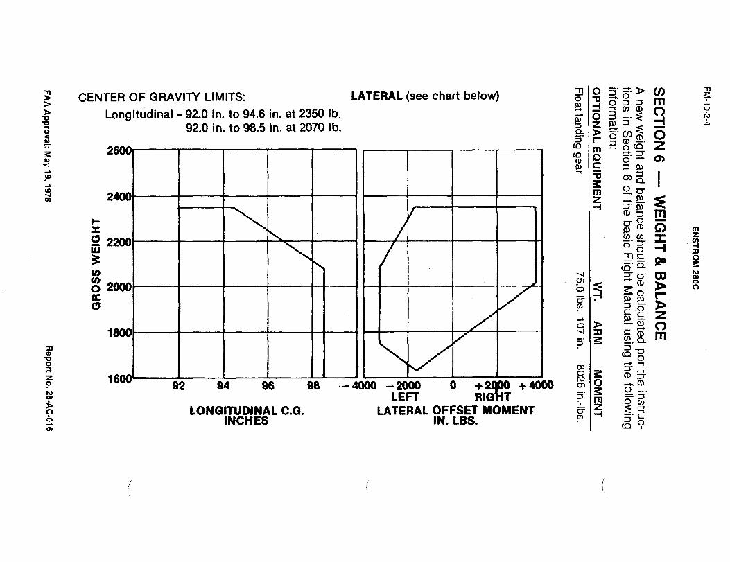
3 -n a 3 V) 71
CENTER OF GRAVITY LIMITS: LATERAL (see chart below) 0 ’II ~h 3 4
f~? O
Longitudinal 92.0 in. to 94.6 in. at 2350 Ib.V, (D O o
03a
a 92.0 in. to 98.5 in. at 2070 Ib. 3 Z~U 3
ng doV>(D O
3Tj(D Z(3 3(3r (3 r.3n, cp
D 3 0)u 9, C 3 Q]
co -Oa
S 2 n E?c~a, IJ~ r
cr>~mo
t~ CD C) mI P,
O v, v, I Z
03V,
W 3 -I7~ 3 3
a 09cn
u, OPu, rn ’Da 2000 ~o 3
n ra K ~o 2,
’3, Z3o~ Z~O
1 "D r <D m>3 "a
-P (Do1 03 3
o~ (D3 1 ru a -h (DO Q2 Q4 Q8 ´•~9000 -2000 O +4000 cno
LEFT 3
~i+m ov,
3 LONGlfUDINAL C.G. LATERAL OFFSET MOMENTI Z~--I r6 INCHES IN, LBS. v,
~oca
rn

FM-10-2-5
ENSTROM´• 280C
Figure 5.1 V ne~r e’xee~-:vs. density altitude
12000
ti loooo
c3 BM)O
sooo VNE FORFLOAT EQUIPPED
MODELS F-28C ANDw 280C 2350 LBS.P 4000
2000
0 20 40 ´•60 80 100 120
CALIBRATED AIRSPEED MPH
FAA Approval: May 19, 1978 Report No. 28-AC-016

FM-1 0-2-6
ENSTROM 2800
AIRSPEED CALIBRATION
MODEL 280C
2350 LBS.
WITH FLOATS i
100
IAQ.
EP 80ww
u,pc:
so
PW
Oe 40rp
20NOTE: ZERO INSTRUMENT ERROR R
0 20 ´•40 60 80 100
COCKPIT INDICATED AIRSPEED (MPH)(PITOT TUBE INSTALLED IN NOSE)
INSTRUMENT ERROR ZERO
FAA Approval: April 20, 1978
Revised: Feb. 17, 1989 Report No. 28-AC-016

FM-10-3-1
ENsTRoM 280C
EXTERNAL LOADS:SUPP~EM:ENT NO. 3
SECTION 1 GENERAL
This supplement must be attached to the Basic Flight Manual
when the Enstrom Cargo Hook Kit No. 28-22000 is installed and
utilized for transportation of external cargo. Operation in compli-ance with Section 2 Operating Limitations of the Basic
Manual is mandatory except as modified by this supplement.Other approved sections and supplemental data are recom-
mended procedures.This aircraft is certified for multiple certificate operation at gross
weight up to 2600 Ibs. for restricted category cargo hook opera-tion when in or converted to the 2350 Ibs. configuration (IIANVEnstrom Drawing 28-100005). A log book entry shall be made
when changing category of operation.
The Cargo Hook Kit incorporates electro-mechanical cargorelease features.
SECTION 2 OPERATING LIMITATIONS
ENGINE LIMITS 2900 RPM, 36.5 in. M.A.P. (205 H.P.)
AIRSPEED LIMITATIONS
Do not exceed approved flight manual speeds.CAUTION
The maximum safe airspeed for satisfactory handling character-
istics is dependent on many variables, i.e. aerodynamic shapeload, c.g, of load, length of sling, location of suspension pointsand rate of climb or descent. caution should be exercised as the
onset of unsdtisfactory handling characteristics may be abrupt.
Restricted category operations 2350 Ibs. to 2600 Ibs.
maximum oPerati:ng:speedl85 Mph IAS at sea level poweron and power off, linear decrease to 80 mph IAS at 6000
feet density altitude.
ALTITUDE LIMITATIONS
For Gross Weights up to 2350 Ibs.: See Approved FlightManual. Restricted category operations 2350 Ibs. to 2600 Ibs.:
6000 feet density altitude.
WEIGHT LIMITATIONS
Do not exceed approved ilight manual-weight limitations.
Restricted category operations: The total weight of the helicopterand load combination shall not exceed 2600 Ibs. See FAR 133,Subpart D.
Maximum ExternalLoad 1,0001bs.FAA Approval: July 28, 1978
Revised: August 15, 1979 Report No. 28-AC-016
I.I-´•´•--´• ´•-´•1´•-´•----´•-´•´•--´•´•´•-´•;´•:---´•´•;---´•´•´•´• --´•--´•´•´•´•´•11---1---´•´•-´•-------´•--´•-- ;´•-I-´•´•´•´•´•´•´•----

FM-1 0-3-2
ENSTROM 280e
CENTER OF G,RAVITY LIMITATIONS
For weights 2350 Ibs. and under: See Approved Flight Manual.
Restricted Category operations above 2350 Ibs.: Forward 86.5
in., rearward 98.0 in.
Lateral offset moment: For weights 2350 Ibs. and under: See
Approved Flight Manual.
Restricted category operations above 2350 Ibs.: 3180 in. Ibs.
to 1855in.lbs.
TYPE OF OPERATIONS
Approved for multiple certificate operations under provisions of
FAR 133 for Class B Rotorcraft-Load Combinations when in the
2350 Ibs. configuration.Normal operations under CAR Part 6 (FAR Part 27) can be con-
ducted with the cargo hook installed, providing external cargo is
not being transported.
PLACARDS
Approved for Class ´•B Rotorcraft-Load Operation. Occupancylimited to flight crew member when carrying external load.
(Installed on instrument panel).
In view of Pilot: Restricted category never exceed speeds mph.IAS.
PRESSURE OUTSIDE AIR TEMPERATURE "F
ALTITUDE 20 0 20 40 60 80 100
SEA LEVEL 85 85 85 85 85 85 851000 85 85 85 85 85 83 822000 85 85 85 84 83 82 813000 85 85 84 83 82 81 804000 85 84 83 82 81 805000 84 83 82 81 806000 83 82 81 80
EXTERNAL LOAD LIMIT 1,000 LBS.: (Installed on Cargo Hook)
SECTION 3 NORMAL PROCEDURES
Preflight Operation Check
1. Check Electrical Release System
a. Turn master switch on
b. Place instrument panel cargo release arming switch to
the on position
FAA Approval: July 28, 1978
Revised: August 16, 1979 Report No. 28-AC-016

FM-10-3-3
ENSTRoM 280C
c. Place a load (3 IbS. hook beam
d. Press upper switch on pilots cyclic grip and the beam
will release. If the momentary release switch is held in
the on position the cargo hook beam will not relatch.
After the switch is released check to see if beam auto-
matically relatches.
2. Check Mechanical Release System (Emergency Release)
a. All switches off
b. Place load (3 Ibs. Min.) on cargo hook beam
c. Activate Emergency Release by pulling the "T" handle
mounted on the pilots cyclic stick. Approximately 1.5
inches of travel is required to release the cargo hook
beam.
d. After load releases push "T" handle in and check hook
beam for automatic relatchjng.
STATIC ELECTRICITY DISCHARGE
Provide ground crew with instructions as follows: Discharge heli-
copter static electricity before attaching cargo by touching the
airframe with a ground wire or if a metal sling is used, the hook-
up ring can be struck against the cargo hook. If contact has
been lost after initial grounding, the helicopter should be electri-
cally regrounded and, if possible, contact maintained until hook-
up completed.
CARGO HOOK OPERATION
Position instrument panel CBRGO RELEASE arming switch (cir-cult breaker) to OFFwhen attaching cargo, then move switch to
ON as desired during approach for release. When cargo release
is desired press upper switch on pilots cyclic grip.
SECTION 4 EMERGENCY PROCEDURES
Pull mechanical manual release handle located on the pilotscyclic stick just forward of th~e cyclic grip, to drop cargo in the
event of an electrical failure.
NOTE
The cargo mechanical release will function regardless of posi-tion of CARGO RELEASE arming switch:
FAA Approval: July 28, 1978
Revised: August 15, 1979 Report No. 28-Ac-016
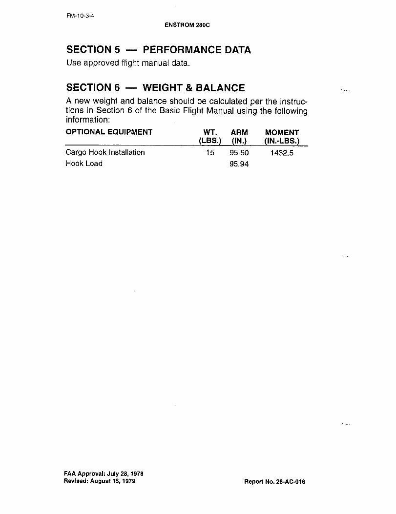
FM-1 0-3-4
ENSTROM 280@
SECTION 5 PERFORMANCE DATA
Use approved flight manual data.
SECTION 6 WEIGHT BALANCE
A new weight and balance should be calculated per the instruc-tions in Section 6 of the Basic Flight Manual using the followinginformation:
OPTIONAL EQUIPMENT WT. ARM MOMENT
(LBS.) (IN.) (IN.-LBS.)
Cargo Hook Installation 15 95.50 1432. 5
Hook Load 95.94
FAA Approval: July 28, i 978
Revised: August 15, 1979 Report No. 28-40-016

FM-10-4-1
ENSTRoM 2800
SNOWSHOE SUPPLEMENTNO. 4
SECTION 1--~GENERAL
This supplement must be attached to the Basic Flight Manual
when the Enstrom nowshoe Kit No. 28-22400 is installed.
Operation in compliance with Section 2 OPERATING LIMI-
TATIONS of the Basic Flight Manual is mandatory except as
modified by this supplement. Other apprQved sections and sup-
plemental data are recommended procedi~res.
The Snowshoe Kit consists of four snowshoe pads, two on each
skid tube, and will permit landings in various snow conditions.
SECTION 2 OPERATING LIMITATIONS
AIRSPEED LIMITATIONS Same as Basic Flight Manual
WEIGHT LIMITATIONS Same as Basic Flight Manual
CENTER OF GRAVITY LIMITATIONS Same as Basic FlightManual
SECTION 6 WEIGHT BALANCE
A new weight and balance should be calculated per the instruc-
tions in Section 6 off the Basic Flight Manual using the followinginformation:
OPTIONAL EQUIPMENT WT. ARM MOMENT
(LBS.) (IN.) (IN.-LBS.)
Snowshoe Kit 18.0 100.9 1816.2
FAA Approval: April 20, 1978
Revised: Feb. 17, 1989 Report No. 28-AC-016

NOTES