en/RLON-01 LONWORKS Adapter Module User's ManualRLON-01 LONWORKSfi Adapter module The RLON-01...
82
ABB Drives Users Manual LONWORKS fi Adapter Module RLON-01
Transcript of en/RLON-01 LONWORKS Adapter Module User's ManualRLON-01 LONWORKSfi Adapter module The RLON-01...

ABB Drives
User�s ManualLONWORKS® Adapter ModuleRLON-01

LONWORKS® Adapter ModuleRLON-01
User�s Manual
3AFE64798693 REV B EN
EFFECTIVE: 07.12.2006
© 2006 ABB Oy. All Rights Reserved.

5
Table of contents
Table of contents . . . . . . . . . . . . . . . . . . . . . . . . . . . . . . . . . . . . . . . . . . . . . 5
Safety instructions . . . . . . . . . . . . . . . . . . . . . . . . . . . . . . . . . . . . . . . . . . . . 9
Overview . . . . . . . . . . . . . . . . . . . . . . . . . . . . . . . . . . . . . . . . . . . . . . . . . . . . 9Warnings and notes . . . . . . . . . . . . . . . . . . . . . . . . . . . . . . . . . . . . . . . . . . . . 9
Warnings . . . . . . . . . . . . . . . . . . . . . . . . . . . . . . . . . . . . . . . . . . . . . . . . . . 9Notes . . . . . . . . . . . . . . . . . . . . . . . . . . . . . . . . . . . . . . . . . . . . . . . . . . . . 10
General safety instructions . . . . . . . . . . . . . . . . . . . . . . . . . . . . . . . . . . . . . . 10
Introduction . . . . . . . . . . . . . . . . . . . . . . . . . . . . . . . . . . . . . . . . . . . . . . . . 13
Overview . . . . . . . . . . . . . . . . . . . . . . . . . . . . . . . . . . . . . . . . . . . . . . . . . . . 13Intended audience . . . . . . . . . . . . . . . . . . . . . . . . . . . . . . . . . . . . . . . . . . . . 13What this manual contains . . . . . . . . . . . . . . . . . . . . . . . . . . . . . . . . . . . . . . 13Terms and abbreviations . . . . . . . . . . . . . . . . . . . . . . . . . . . . . . . . . . . . . . . 14Further information . . . . . . . . . . . . . . . . . . . . . . . . . . . . . . . . . . . . . . . . . . . . 16
Overview . . . . . . . . . . . . . . . . . . . . . . . . . . . . . . . . . . . . . . . . . . . . . . . . . . . 17
Overview . . . . . . . . . . . . . . . . . . . . . . . . . . . . . . . . . . . . . . . . . . . . . . . . . . . 17The LonWorks® system . . . . . . . . . . . . . . . . . . . . . . . . . . . . . . . . . . . . . . . . 17The RLON-01 LonWorks® Adapter module . . . . . . . . . . . . . . . . . . . . . . . . . 18
Compatibility . . . . . . . . . . . . . . . . . . . . . . . . . . . . . . . . . . . . . . . . . . . . . . . 19Delivery check . . . . . . . . . . . . . . . . . . . . . . . . . . . . . . . . . . . . . . . . . . . . . 19Warranty and liability information . . . . . . . . . . . . . . . . . . . . . . . . . . . . . . . 20
Mechanical installation . . . . . . . . . . . . . . . . . . . . . . . . . . . . . . . . . . . . . . . 21
Mounting . . . . . . . . . . . . . . . . . . . . . . . . . . . . . . . . . . . . . . . . . . . . . . . . . . . 21
Table of contents
6
Electrical installation . . . . . . . . . . . . . . . . . . . . . . . . . . . . . . . . . . . . . . . . . 23
Overview . . . . . . . . . . . . . . . . . . . . . . . . . . . . . . . . . . . . . . . . . . . . . . . . . . . . 23Cabling . . . . . . . . . . . . . . . . . . . . . . . . . . . . . . . . . . . . . . . . . . . . . . . . . . . . . 23RLON-01 connections . . . . . . . . . . . . . . . . . . . . . . . . . . . . . . . . . . . . . . . . . . 24Bus termination . . . . . . . . . . . . . . . . . . . . . . . . . . . . . . . . . . . . . . . . . . . . . . . 24Earthing the LonWorks® cable screens . . . . . . . . . . . . . . . . . . . . . . . . . . . . 25
Programming . . . . . . . . . . . . . . . . . . . . . . . . . . . . . . . . . . . . . . . . . . . . . . . . 27
Overview . . . . . . . . . . . . . . . . . . . . . . . . . . . . . . . . . . . . . . . . . . . . . . . . . . . . 27Configuring the system . . . . . . . . . . . . . . . . . . . . . . . . . . . . . . . . . . . . . . . . . 27Configuring the drive . . . . . . . . . . . . . . . . . . . . . . . . . . . . . . . . . . . . . . . . . . . 27
Drive parameter settings . . . . . . . . . . . . . . . . . . . . . . . . . . . . . . . . . . . . . . 33
ACx550 parameter settings . . . . . . . . . . . . . . . . . . . . . . . . . . . . . . . . . . . . . 33ACS800 parameter settings . . . . . . . . . . . . . . . . . . . . . . . . . . . . . . . . . . . . . 35
Communication . . . . . . . . . . . . . . . . . . . . . . . . . . . . . . . . . . . . . . . . . . . . . . 37
Overview . . . . . . . . . . . . . . . . . . . . . . . . . . . . . . . . . . . . . . . . . . . . . . . . . . . . 37General . . . . . . . . . . . . . . . . . . . . . . . . . . . . . . . . . . . . . . . . . . . . . . . . . . . . . 37LonMark objects . . . . . . . . . . . . . . . . . . . . . . . . . . . . . . . . . . . . . . . . . . . . . . 37
Node object . . . . . . . . . . . . . . . . . . . . . . . . . . . . . . . . . . . . . . . . . . . . . . . . 38Input network variable . . . . . . . . . . . . . . . . . . . . . . . . . . . . . . . . . . . . . . . . . . 38
NviObjRequest . . . . . . . . . . . . . . . . . . . . . . . . . . . . . . . . . . . . . . . . . . . . . 38Output network variable . . . . . . . . . . . . . . . . . . . . . . . . . . . . . . . . . . . . . . . . 39
NvoObjStatus. . . . . . . . . . . . . . . . . . . . . . . . . . . . . . . . . . . . . . . . . . . . . . . 39Variable speed motor drive object . . . . . . . . . . . . . . . . . . . . . . . . . . . . . . . . 40Resource files . . . . . . . . . . . . . . . . . . . . . . . . . . . . . . . . . . . . . . . . . . . . . . . . 41
Network variables . . . . . . . . . . . . . . . . . . . . . . . . . . . . . . . . . . . . . . . . . . . . 43
Supported input network variables . . . . . . . . . . . . . . . . . . . . . . . . . . . . . . . . 43NviDrvSpeedStpt . . . . . . . . . . . . . . . . . . . . . . . . . . . . . . . . . . . . . . . . . . . . 44NviDrvSpeedScale . . . . . . . . . . . . . . . . . . . . . . . . . . . . . . . . . . . . . . . . . . 45NviResetFault . . . . . . . . . . . . . . . . . . . . . . . . . . . . . . . . . . . . . . . . . . . . . . 45NviEmergOverride . . . . . . . . . . . . . . . . . . . . . . . . . . . . . . . . . . . . . . . . . . . 46
Table of contents
7
NviDigOutput . . . . . . . . . . . . . . . . . . . . . . . . . . . . . . . . . . . . . . . . . . . . . . 47NviDigOutput1 . . . . . . . . . . . . . . . . . . . . . . . . . . . . . . . . . . . . . . . . . . . . . 48NviDigOutput2 . . . . . . . . . . . . . . . . . . . . . . . . . . . . . . . . . . . . . . . . . . . . . 48NviExt1Ext2Ctrl . . . . . . . . . . . . . . . . . . . . . . . . . . . . . . . . . . . . . . . . . . . . 49
Supported output network variables . . . . . . . . . . . . . . . . . . . . . . . . . . . . . . . 50NvoDrvSpeed . . . . . . . . . . . . . . . . . . . . . . . . . . . . . . . . . . . . . . . . . . . . . . 51NvoDrvCurnt . . . . . . . . . . . . . . . . . . . . . . . . . . . . . . . . . . . . . . . . . . . . . . . 51NvoDrvPwr . . . . . . . . . . . . . . . . . . . . . . . . . . . . . . . . . . . . . . . . . . . . . . . . 51NvoDrvRunHours . . . . . . . . . . . . . . . . . . . . . . . . . . . . . . . . . . . . . . . . . . . 52NvoDrvVolt . . . . . . . . . . . . . . . . . . . . . . . . . . . . . . . . . . . . . . . . . . . . . . . . 52NvoSpeedActRpm . . . . . . . . . . . . . . . . . . . . . . . . . . . . . . . . . . . . . . . . . . 52NvoDrvTemp . . . . . . . . . . . . . . . . . . . . . . . . . . . . . . . . . . . . . . . . . . . . . . 53NvoFreqAct . . . . . . . . . . . . . . . . . . . . . . . . . . . . . . . . . . . . . . . . . . . . . . . . 53NvoDrvStatus . . . . . . . . . . . . . . . . . . . . . . . . . . . . . . . . . . . . . . . . . . . . . . 54NvoRunning . . . . . . . . . . . . . . . . . . . . . . . . . . . . . . . . . . . . . . . . . . . . . . . 55NvoFaulted . . . . . . . . . . . . . . . . . . . . . . . . . . . . . . . . . . . . . . . . . . . . . . . . 55NvoPidAct . . . . . . . . . . . . . . . . . . . . . . . . . . . . . . . . . . . . . . . . . . . . . . . . . 55NvoEmergOvrStat . . . . . . . . . . . . . . . . . . . . . . . . . . . . . . . . . . . . . . . . . . 56NvoDigInput1 . . . . . . . . . . . . . . . . . . . . . . . . . . . . . . . . . . . . . . . . . . . . . . 56NvoDigInput2 . . . . . . . . . . . . . . . . . . . . . . . . . . . . . . . . . . . . . . . . . . . . . . 57NvoAnlgInput . . . . . . . . . . . . . . . . . . . . . . . . . . . . . . . . . . . . . . . . . . . . . . 57NvoParValue . . . . . . . . . . . . . . . . . . . . . . . . . . . . . . . . . . . . . . . . . . . . . . 58NvoDigIOStat . . . . . . . . . . . . . . . . . . . . . . . . . . . . . . . . . . . . . . . . . . . . . . 58NvoExt1Ext2Stat . . . . . . . . . . . . . . . . . . . . . . . . . . . . . . . . . . . . . . . . . . . 59NvoLocRemStat . . . . . . . . . . . . . . . . . . . . . . . . . . . . . . . . . . . . . . . . . . . . 60NvoLastFault . . . . . . . . . . . . . . . . . . . . . . . . . . . . . . . . . . . . . . . . . . . . . . 60
Supported network configuration properties . . . . . . . . . . . . . . . . . . . . . . . . . 61SCPTmaxSendTime / nciSndHrtBt . . . . . . . . . . . . . . . . . . . . . . . . . . . . . . 62SCPTmaxRcvTime / nciRcvHrtBt . . . . . . . . . . . . . . . . . . . . . . . . . . . . . . . 63SCPTminSendTime / nciMinOutTm . . . . . . . . . . . . . . . . . . . . . . . . . . . . . 63SCPTnomRPM / nciNmlSpeed . . . . . . . . . . . . . . . . . . . . . . . . . . . . . . . . . 64SCPTnomFreq / nciNmlFreq . . . . . . . . . . . . . . . . . . . . . . . . . . . . . . . . . . 64SCPTminSetpoint / nciMinSpeed . . . . . . . . . . . . . . . . . . . . . . . . . . . . . . . 65SCPTmaxSetpoint / nciMaxSpeed . . . . . . . . . . . . . . . . . . . . . . . . . . . . . . 65SCPTrampUpTm / nciRampUpTm . . . . . . . . . . . . . . . . . . . . . . . . . . . . . . 66SCPTrampDownTm / nciRampDownTm . . . . . . . . . . . . . . . . . . . . . . . . . 66SCPTlocation / nciLocation . . . . . . . . . . . . . . . . . . . . . . . . . . . . . . . . . . . 67SCPTdefScale / nciDrvSpdScl . . . . . . . . . . . . . . . . . . . . . . . . . . . . . . . . . 67
Table of contents
8
UCPTstopMode / nciStopMode . . . . . . . . . . . . . . . . . . . . . . . . . . . . . . . . . 68UCPTstopLevel / nciStopLevel . . . . . . . . . . . . . . . . . . . . . . . . . . . . . . . . . 68UCPTpidGain / nciPidGain . . . . . . . . . . . . . . . . . . . . . . . . . . . . . . . . . . . . 69UCPTpidIntTime / nciPIDIntTime . . . . . . . . . . . . . . . . . . . . . . . . . . . . . . . 69UCPTpidDerTime / nciPidDerTime . . . . . . . . . . . . . . . . . . . . . . . . . . . . . . 70UCPTparValue / nciParValue . . . . . . . . . . . . . . . . . . . . . . . . . . . . . . . . . . 70UCPTparRead / nciParRead . . . . . . . . . . . . . . . . . . . . . . . . . . . . . . . . . . . 71UCPTparWrite / nciParWrite . . . . . . . . . . . . . . . . . . . . . . . . . . . . . . . . . . . 71
Fault tracing . . . . . . . . . . . . . . . . . . . . . . . . . . . . . . . . . . . . . . . . . . . . . . . . 73
LED indications . . . . . . . . . . . . . . . . . . . . . . . . . . . . . . . . . . . . . . . . . . . . . . . 73
Technical data . . . . . . . . . . . . . . . . . . . . . . . . . . . . . . . . . . . . . . . . . . . . . . . 75
RLON-01 . . . . . . . . . . . . . . . . . . . . . . . . . . . . . . . . . . . . . . . . . . . . . . . . . . . . 75LonWorks® network . . . . . . . . . . . . . . . . . . . . . . . . . . . . . . . . . . . . . . . . . . . 76
Table of contents
9
Safety instructions
OverviewThis chapter states the safety instructions that must be followed when installing and operating the RLON-01 LONWORKS® Adapter module. The material in this chapter must be studied before attempting any work on, or with, the unit.
Warnings and notesThis manual distinguishes two sorts of safety instructions. Warnings are used to inform of conditions which can, if proper steps are not taken, lead to a serious fault condition, physical injury and death. Notes are used when the reader is required to pay special attention or when there is additional information available on the subject. Notes are less crucial than Warnings, but should not be disregarded.
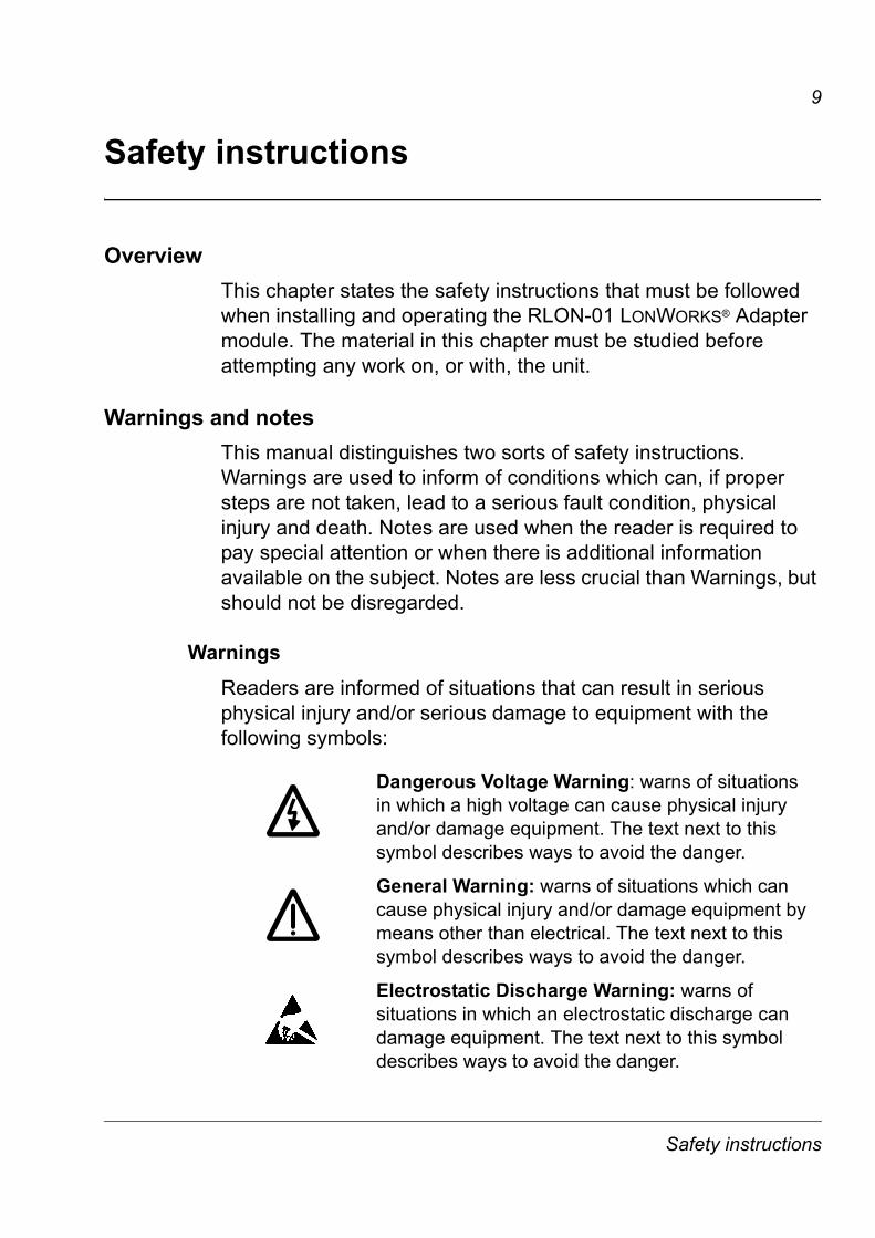
WarningsReaders are informed of situations that can result in serious physical injury and/or serious damage to equipment with the following symbols:
Dangerous Voltage Warning: warns of situations in which a high voltage can cause physical injury and/or damage equipment. The text next to this symbol describes ways to avoid the danger.
General Warning: warns of situations which can cause physical injury and/or damage equipment by means other than electrical. The text next to this symbol describes ways to avoid the danger.
Electrostatic Discharge Warning: warns of situations in which an electrostatic discharge can damage equipment. The text next to this symbol describes ways to avoid the danger.
Safety instructions
10
NotesReaders are notified of the need for special attention or additional information available on the subject with the following symbols:
General safety instructionsWARNING! All electrical installation and maintenance work on the drive should be carried out by qualified electricians.
The drive and adjoining equipment must be properly earthed.
Do not attempt any work on a powered drive. After switching off the mains, always allow the intermediate circuit capacitors 5 minutes to discharge before working on the drive, the motor or the motor cable. It is good practice to check (with a voltage indicating instrument) that the drive is in fact discharged before beginning work.
The motor cable terminals of the drive are at a dangerously high voltage when mains power is applied, regardless of motor operation.
There can be dangerous voltages inside the drive from external control circuits even when the drive mains power is shut off. Exercise appropriate care when working with the unit. Neglecting these instructions can cause physical injury and death.
WARNING! There are several automatic reset functions in thedrive. If selected, they reset the unit and resume operation after a fault. These functions should not be selected if other equipment is not compatible with this kind of operation, or dangerous situations can be caused by such action.
More Warnings and Notes are printed at appropriate instances along the text.
WARNING! Warning aims to draw special attention to a partic-ular issue.
Note: Note gives additional information or points out more information available on the subject.
Safety instructions

11
The General Safety Instructions given in the Installation and Start-up Manual of the drive should be studied before attempting any work on or with the unit.
Safety instructions

12
Safety instructions
13
Introduction
OverviewThis chapter contains a description of the User�s manual for the RLON-01 LONWORKS® Adapter module.
Intended audienceThe guide is intended for people responsible for installing, commissioning, and using the RLON-01 LONWORKS® Adapter module with an ABB drive. The reader is expected to have a basic knowledge of
� electrical fundamentals and wiring practices
� the drive and its control panel
� the host controller software.
What this manual containsThe installation and start-up of the RLON-01 LONWORKS® Adapter module are introduced in this manual.
It is assumed that the drive is installed and ready to operate before starting the installation of the adapter module. For more information on the installation and start-up procedures of the drive, please refer to its user documentation.
Safety Instructions are featured in the first few pages of this manual.
Introduction contains a short description of the manual.
Overview contains a short description of the LONWORKS® system and the RLON-01 LONWORKS® Adapter module, a delivery checklist, and information on the manufacturer�s warranty.
Mechanical installation contains the placing and mounting instructions for the module.
Electrical installation contains the wiring instructions.
Introduction
14
Programming explains how to program the master station and the drive before the communication through the adapter module can be started.
Communication contains a description of how data is transmitted through the RLON-01 and information about resource files.
Fault Tracing explains how to trace faults with the Status LEDs on the RLON-01.
Network variables presents the network variable list of the RLON-01.
Technical data contains information on physical dimensions, configurable settings and connectors of the module and a specification of the fieldbus link.
Terms and abbreviationsCommunication Module
Communication Module is a parameter name/parameter selection name for a device (e.g. a fieldbus adapter) through which the drive is connected to an external serial communication network (e.g. a fieldbus). The communication with the communication module is activated by a drive parameter.
CRC
Cyclic Redundancy Check
Data Words
The Control Word (sometimes called the Command Word) and the Status Word, References and Actual Values (see chapter Communication) are types of data words; the contents of some data words are user-definable. For more information, see the drive documentation.
Introduction
15
Functional profile
Functional profiles may contain one or more objects that interact to perform the required profile defined operability. The Variable Speed Motor Drive Profile contains the general LONMARK® Node Object and the application specific Variable Speed Motor Drive Object.
LonMark®
Products that conform to LONMARK® Interoperability Guidelines, defined by the LONMARK® Interoperability Association, are eligible to carry the LONMARK® logo.
LonTalk®
The communication protocol in LONWORKS® networks
LSB
Least significant bit
MSB
Most significant bit
nci
Network configuration variable
Neuron® ID
Every LONWORKS® device or � as synonym � node must have a unique ID. This is called the Neuron® ID. This ID is, on Neuron® Chip-based nodes, stored in the chip itself and cannot be changed.
RLON-01 LONWORKS® Adapter module
The RLON-01 Adapter module is one of the optional fieldbus adapter modules available for ABB drives. The RLON-01 is a device through which the drive is connected to a LONWORKS® network.
nv
Network variable
Introduction

16
nvi
Input network variable
nvo
Output network variable
Object
Object is a set of one or more network variables implemented as SNVTs with semantic definitions relating the behaviour of the object to the network variable values, in addition to a set of configuration properties. For example, the Variable Speed Motor Drive Object and the Node Object represent two types of objects.
Parameter
A parameter is an operating instruction for the drive. Parameters can be read and programmed by using the drive control panel, or through the RLON-01 module.
Service Pin
The Service Pin is used in installing the node. Pressing the Service Pin causes the LONWORKS® node to send the so-called Service Pin Message which includes, among other things, the Neuron® ID. This informs the network or installation tool about the node.
SNVT
Standard Network Variable Type
UCPT
User Configuration Property Type
Further informationFurther information is available on the WWW from www.lonmark.org and www.echelon.com.
Introduction
17
Overview
Overview This chapter contains a short description of the LONWORKS® system and the RLON-01 Adapter module, a delivery checklist, and warranty information.
The LONWORKS® systemThe LONWORKS® system is an open serial communication solution that enables data exchange between all kinds of automation components.
A LONWORKS® network consists of intelligent devices, called nodes, connected by one or more communications media that communicate with one another using the LonTalk® protocol. A LONWORKS® network can consist of up to 32385 nodes divided into 255 subnets (127 nodes/subnet). Nodes are programmed to send messages to one another in response to external events or messages they receive. Each intelligent device, for example a programmable thermostat in a building control system, is a LONWORKS® node. A node is connected to other nodes with appropriate communications media, such as twisted pair cable, RF link, or power line circuit.
Each node includes a physical interface, transceiver that interfaces with the communication media. The RLON-01 module uses the FT-X1 Free Topology Transceiver (compatible with FTT-10A transceiver) from Echelon Corporation. This is the most commonly used twisted-pair media in building automation and this architecture supports star, bus, and loop wiring. The FT-X1 transceiver connects to a twisted pair cable with a baud rate of 78 kbit/s and appears as a high impedance to the network when unpowered, hence it does not interfere with the network communications when powered down.
Overview
18
LONWORKS® nodes are objects that respond to various inputs and that produce desired outputs. Connecting the inputs and outputs of these network objects enables the network to perform specific tasks.
While the function of any particular node may be quite simple, the interaction among nodes enables a LONWORKS® network to perform complex tasks. A benefit of LONWORKS® networks is that a small number of common node types may perform a broad spectrum of different functions depending on how they are configured and connected.
The RLON-01 LONWORKS® Adapter moduleThe RLON-01 LONWORKS® Adapter module is an optional device for ABB drives which enables the connection of the drive to a LONWORKS® network. Through the RLON-01 LONWORKS® Adapter module it is possible to:
� give control commands to the drive(Start, Stop, Run enable, etc.)
� feed speed or frequency reference to the drive
� give a process actual value or a process reference to the PID controller of the drive
� read status information and actual values from the drive
� change drive parameter values
� reset a drive fault
� control other LONWORKS® nodes.
The network variables and functions supported by the RLON-01 LONWORKS® Adapter module are discussed in chapters Programming and Communication.
The adapter module is mounted into an option slot on the motor control board of the drive. See the Hardware Manual of the drive for module placement options.
Overview
19
CompatibilityThe RLON-01 is compatible with
� ACS550 and ACH550
� ACS800 Standard Application Program ASXR7010 or later.
Delivery checkThe option package for the RLON-01 LONWORKS® Adapter module contains
� LONWORKS® Adapter module, type RLON-01
� two screws (M3x10)
� this manual.
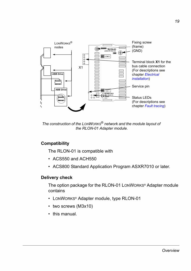
ABB Drive
LONWORKS® nodes
Status LEDs(For descriptions see chapter Fault tracing)
Service pin
Terminal block X1 for the bus cable connection (For descriptions see chapter Electrical installation)
ABB Drive
X1
Fixing screw(frame)(GND)
The construction of the LONWORKS® network and the module layout of the RLON-01 Adapter module.
Overview
20
Warranty and liability informationThe manufacturer warrants the equipment supplied against defects in design, materials and workmanship for a period of twelve (12) months after installation or twenty-four (24) months from date of manufacturing, whichever first occurs. The local ABB office or distributor may grant a warranty period different to the above and refer to local terms of liability as defined in the supply contract.
The manufacturer is not responsible for
� any costs resulting from a failure if the installation, commissioning, repair, alternation, or ambient conditions of the drive do not fulfil the requirements specified in the documentation delivered with the unit and other relevant documentation
� units subjected to misuse, negligence or accident
� units comprised of materials provided or designs stipulated by the purchaser.
In no event shall the manufacturer, its suppliers or subcontractors be liable for special, indirect, incidental or consequential damages, losses or penalties.
If you have any questions concerning your ABB drive, please contact the local distributor or ABB office. The technical data, information and specifications are valid at the time of printing. The manufacturer reserves the right to modifications without prior notice.
Overview
21
Mechanical installation
WARNING! Follow the safety instructions given in this manual and in the Hardware Manual.
MountingThe RLON-01 is to be inserted into its option slot inside the drive. The module is held in place with plastic retaining clips and two screws. The screws also provide the earthing of the I/O cable shield connected to the module, and interconnect the GND signals of the module and the control board of the drive.
On installation of the module, the signal and power connection to the drive is automatically made through a 34-pin connector.
Mounting procedure:
� Insert the module carefully into its position inside the drive until the retaining clips lock the module into position.
� Fasten the two screws (included).
Note: Correct installation of the screws is essential for fulfilling the EMC requirements and for proper operation of the module.
Mechanical installation

22
Mechanical installation
23
Electrical installation
OverviewThis chapter contains
� cabling instructions
� instructions for bus termination
� connection instructions for the RLON-01 module and earthing instructions for the bus cable.
WARNING! Before installation, switch off the drive power supply. Wait for five minutes to ensure that the capacitor bank of the drive is discharged. Switch off all dangerous voltages connected from external control circuits to the inputs and outputs of the drive.
CablingArrange the bus cables as far away from the motor cables as possible. Avoid parallel runs. Use bushings at cable entries.
Note: LONWORKS® networks require special cable. It is recommended to use cables defined by LONMARK® Layer 1-6 Guidelines. See chapter Technical data.
Electrical installation
24
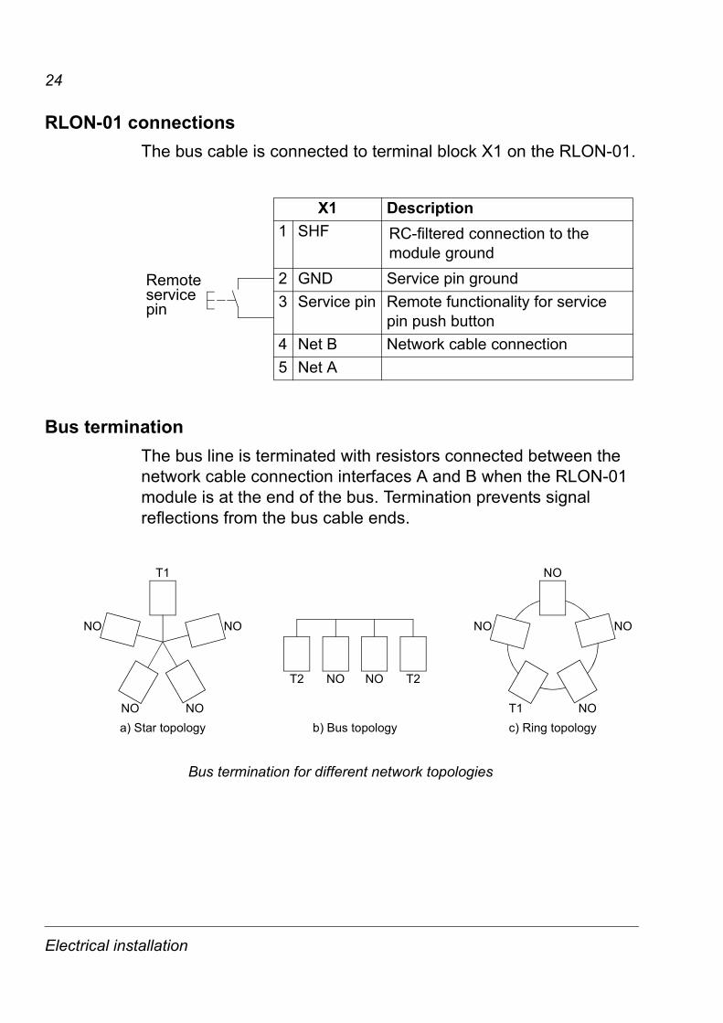
RLON-01 connectionsThe bus cable is connected to terminal block X1 on the RLON-01.
Bus terminationThe bus line is terminated with resistors connected between the network cable connection interfaces A and B when the RLON-01 module is at the end of the bus. Termination prevents signal reflections from the bus cable ends.
Remote service pin
X1 Description1 SHF RC-filtered connection to the
module ground2 GND Service pin ground3 Service pin Remote functionality for service
pin push button4 Net B Network cable connection5 Net A
a) Star topology b) Bus topology c) Ring topology
NO
T1
NO
NO
NO
NONO
NONO
NONO T2T2
T1
Bus termination for different network topologies
Electrical installation
25
Earthing the LONWORKS® cable screensThe LONWORKS® cable screen can be directly earthed at one station only. At other stations the screen should be earthed via an RC filter.
Different bus terminationsT1 52.5 ohm termination at one of the nodes in one bus
segment
T2 105 ohm termination at both ends of the line
NO No termination
SHF
Net
B
Net
A X1
RLON-01
SHF X1
SHF
RLON-01RLON-01
4 5 X1
Net
B
Net
A
4 5
Net
B
Net
A
4 5
105 Ω 105 Ω
Network cable connection for bus topology.
Electrical installation

26
Electrical installation
27
Programming
OverviewThis chapter gives information on configuring the drive for operation with the LONWORKS® Adapter module.
Configuring the systemAfter the RLON-01 LONWORKS® Adapter module has been mechanically and electrically installed according to the instructions given in chapters 3 and 4, the LONWORKS® network and the drive must be prepared for communication and operation with the module.
The RLON-01 cannot communicate with the drive before it is configured for the LONWORKS® network. The LONWORKS® communication configuration does not require parametrisation of the drive. The LONWORKS® network is configured using a network installation tool. Please, refer to the installation tool documentation for network configuration and to chapter Communication for the resource files.
Configuring the drive It is preferable to configure the drive before the RLON-01 is configured for the network. The reason for this is that the RLON-01 reads several parameter values from the drive in order to operate correctly and in order to select different modes. Furthermore, some of the configuration network variable values receive their defaults from the drive. The drive control location parameters should also be set accordingly to enable full and logical operation of the RLON-01. See chapter Drive parameter settings.
Programming
28
Note: These parameters become visible in the drive only after the RLON-01 has been configured on the network side.
RLON-01 information parameters
Fieldbuspar. no.
Parameter name Description
1 MODULE TYPE Type of the module (LonWorks)
2 NODE STATE State of the RLON-01
3-8 NEURON ID [5...0] Neuron® chip ID
9 NODE ADRESS 1 ID of the node within this subnet
10 NODE SUBNET 1 Subnet to which the node belongs
11-16 DOMAIN ID 1 [4...0] Domain ID in a LonWorks network
17 NODE ADRESS 2 ID of the node within this subnet
19-24 DOMAIN ID 2 [4...0] ID in a LonWorks network
25 XMIT ERRORS Number of CRC errors
26 TRANS TIMEOUTS Number of transmission failures
Programming
29
MODULE TYPE
Explanation:
Shows the module type as detected by the drive. The value cannot be adjusted by the user. (If this parameter is undefined, the communication between the drive and the module has not been established.)
NODE STATE
Explanation:
Contains the current state of the network interface. Configured on-line is the normal run-time mode and means that the node is commissioned and on-line on the network. Soft/Bypass/Hard off-line means that the node is not participating actively on the network.
0 = Unknown state
1 = Unconfigured
2 = Applicationless
3 = Configured on-line
4 = Configured off-line
5 = Soft off-line
6 = Configured bypass off-line
7 = Hard off-line, Bypass off-line
Programming
30
NEURON ID
Explanation:
Displays the Neuron® chip ID of the module in decimal format. The ID is determined by the chip and cannot be changed.
NEURON ID [5] = byte 6 of the unique Neuron ID (MSB)
NEURON ID [4] = byte 5 of the unique Neuron ID
NEURON ID [3] = byte 4 of the unique Neuron ID
NEURON ID [2] = byte 3 of the unique Neuron ID
NEURON ID [1] = byte 2 of the unique Neuron ID
NEURON ID [0] = byte 1 of the unique Neuron ID (LSB)
NODE ADRESS 1
Indicates the ID of the node within the subnet.
Range:
1-127
0 means that the node address 1 is not assigned.
NODE SUBNET 1
Explanation:
Indicates to which subnet the node belongs.
Range:
1-255
0 means that the node subnet 1 is not assigned.
Programming
31
DOMAIN ID 1
Explanation:
Indicates the ID of the domain within this subnet. Each domain in a LonWorks® network has a unique ID of 0, 1, 3 or 6 bytes in length. If the ID is shorter than 6 bytes, it is left justified in this field.
DOMAIN ID 1 [5] = byte 6 of the domain ID (MSB)
DOMAIN ID 1 [4] = byte 5 of the domain ID
DOMAIN ID 1 [3] = byte 4 of the domain ID
DOMAIN ID 1 [2] = byte 3 of the domain ID
DOMAIN ID 1 [1] = byte 2 of the domain ID
DOMAIN ID 1 [0] = byte 1 of the domain ID (LSB)
NODE ADRESS 2
Explanation:
Indicates the ID of the node within this subnet.
Range:
1-127
0 means that the node address is not assigned.
Programming
32
DOMAIN ID 2
Explanation:
Indicates the ID of the domain within this subnet. Each domain in a LonWorks® network has a unique ID of 0,1,3 or 6 bytes in length. If the ID is shorter than 6 bytes, it is left justified in this field.
DOMAIN ID 2 [5] = byte 6 of the domain ID (MSB)
DOMAIN ID 2 [4] = byte 5 of the domain ID
DOMAIN ID 2 [3] = byte 4 of the domain ID
DOMAIN ID 2 [2] = byte 3 of the domain ID
DOMAIN ID 2 [1] = byte 2 of the domain ID
DOMAIN ID 2 [0] = byte 1 of the domain ID (LSB)
XMIT ERRORS
Explanation:
Indicates the number of CRC errors detected during packet reception. An increasing value may be due to collisions or noise on the transceiver input.
TRANS TIMEOUTS
Explanation:
Indicates the number of times that the node failed to receive expected acknowledgements or responses after retrying configuring number of times. An increasing value may be due to destination nodes being inaccessible on the network, transmission failures because of noise on the channel, or if any destination node has insufficient buffers or receive transaction records.
Programming

33
Drive parameter settings
ACx550 parameter settings
Parameter Setting Function
9904 MOTOR CTRL MODE
Motor control mode SPEED; SCALAR
Initialises RLON-01 operation mode.
9907 MOTOR NOM FREQ*
Motor nominal frequency
Initialises the nciNmlFreq value.
9908 MOTOR NOM SPEED*
Motor nominal speed Initialises the nciNmlSpeed value. This value corresponds to nviSpeedStpt value 100% (of nominal speed or frequency).
1001 EXT1 COMMANDS
COMM Enables network control of the drive.
1003 DIRECTION REQUEST Enables change of direction.
1102 EXT1/EXT2 SEL COMM Enables the change of external control location via nviExt1Ext2Sel
1103 REF1 SELECT COMM Enables setting the reference 1 via network.
1106 REF2 SELECT COMM Enables setting the reference 1 via network.
1401 RELAY OUTPUT1
COMM Enables control of relay output 1 via nviDigOutput and nviDigOutput1.
1402 RELAY OUTPUT2
COMM Enables control of relay output 2 via nviDigOutput and nviDigOutput2.
1403 RELAY OUTPUT3
COMM Enables control of relay output 3 via nviDigOutput and nviDigOutput1.
1601 RUN ENABLE COMM Enables the run enable command via the network.
Drive parameter settings

34
*If one of the drive parameter values marked with * not using the corresponding configuration network variable is changed, the RLON-01 needs to be re-initialised in order to update it's value. For example, if the stop mode parameter is changed with the control panel, the RLON-01 needs to be either rebooted or temporarily disabled for the RLON-01 to read the updated value from the drive. The same applies if one of the marked parameters using the nciParValue configuration parameter is changed.
1604 FAULT RESET SEL
COMM Enables the fault reset command via the network.
2001 MINIMUM SPEED*
Minimum motor speed.
Initialises nciMinSpeed value.
2002 MAXIMUM SPEED*
Maximum motor speed.
Initialises nciMaxSpeed value.
2007 MINIMUM FREQ*
Minimum output frequency.
Initialises nciMinSpeed value.
2008 MAXIMUM FREQ*
Maximum output frequency.
Initialises nciMaxSpeed value.
2202 ACCELERTIME 1
Acceleration time Initialises nciRampUpTm value.
2203 DECELER TIME 1
Deceleration time Initialises nciRampDownTm value.
4001 GAIN* PID gain Initialises nciPidGain value.
4002 INTEGRATION TIME*
PID integration time Initialises nciPidIntTime value.
4003 DERIVATION TIME*
PID derivation time Initialises nciPidDerTime value.
9802 COMM PROT SEL
EXT FBA Enables fieldbus communication with the drive.
Parameter Setting Function
Drive parameter settings
35
ACS800 parameter settings
Parameter Setting Function
99.02 APPLICATION MACRO*
Set to PID if corresponding network variables are to be used
Enables the updates of nciPidGain, nciPidIntTime and nciPidDerTime.
99.04 MOTOR CTRL MODE
Motor control mode DTC; SCALAR
Initialises RLON-01 operation mode.
99.07 MOTOR NOM FREQ*
Motor nominal frequency
Initialises the nciNmlFreq value.
99.08 MOTOR NOM SPEED*
Motor nominal speed Initialises the nciNmlSpeed value. This value corresponds to nviSpeedStpt value 100% (of nominal speed or frequency).
10.01 EXT1 STRT/STP/DIR
COMM MODULE Enables network control of the drive.
10.03 DIRECTION REQUEST Enables change of direction.
11.02 EXT1/EXT2 SEL
11.09 Enables the change of external control location via pointer parameter 11.09 EXT1/EXT2 SEL PTR.
11.03 EXT REF1 SELECT
COMM MODULE Enables network reference setting.
11.09 EXT1/EXT2 PTR
+.009.006.11 Determines the parameter 11.09 to point to signal 9.06 DS MCW bit 11, which carries the nviExt1Ext2Ctrl command.
16.01 RUN ENABLE COMM MODULE Enables the run enable command via the network.
16.04 FAULT RESET SEL
COMM MODULE Enables the fault reset command via the network.
Drive parameter settings

36
*If one of the drive parameter values marked with * not using the corresponding configuration network variable is changed, the RLON-01 needs to be re-initialised in order to update it's value. For example, if the stop mode parameter is changed with the control panel, the RLON-01 needs to be either rebooted or temporarily disabled for the RLON-01 to read the updated value from the drive. The same applies if one of the marked parameters using the nciParValue configuration parameter is changed.
20.01 MINIMUM SPEED*
Minimum motor speed. Only in DTC mode.
Initialises nciMinSpeed value.
20.02 MAXIMUM SPEED*
Maximum motor speed. Only in DTC mode.
Initialises nciMaxSpeed value.
20.07 MINIMUM FREQ*
Minimum output frequency. Only in SCALAR mode.
Initialises nciMinSpeed value.
20.08 MAXIMUM FREQ*
Maximum output frequency (in SCALAR MODE ONLY)
Initialises nciMaxSpeed value.
22.02 ACCEL TIME1 Acceleration time Initialises nciRampUpTm value.
22.03 DECEL TIME1 Deceleration time Initialises nciRampDownTm value.
40.01 PID GAIN* PID gain Initialises nciPidGain value.
40.02 PID INTEG TIME*
PID integration time Initialises nciPidIntTime value.
40.03 PID DERIV TIME*
PID derivation time Initialises nciPidDerTime value.
98.02 COMM MODULE LINK
FIELDBUS Enables fieldbus communication with the drive.
98.07 COMM PROFILE
GENERIC Enables control of the drive via the Variable Speed Motor Drive object.
Parameter Setting Function
Drive parameter settings
37
Communication
OverviewThis chapter describes the RLON-01 operation on a LONWORKS® network.
GeneralIn LONWORKS® networks, the network design emphasis is on designing the network variable connections. The connection design determines the amount of data flow between different nodes, thus determining the decision of transmission media and network topology overall in the network.
In designing the connections, the selection of protocol services is also crucial when determining the network data flow. By default, the network connections use acknowledged messaging with a certain retry count. This can, however, be changed by the installation tool to optimize the overall network performance.
To be able to realise the required operation of the whole system, a clear picture of the capabilities of individual nodes is needed. These capabilities are determined by the network variables.
LonMark objectsThe RLON-01 includes two objects, a node object and a drive object. The node object is used to control the drive object. The drive object realises the LONMARK® Functional Profile: �Variable Speed Motor Drive Version�, 1.1. The profile defines a set of network variables and configuration properties. In addition, the drive object includes a set of manufacturer defined network variables and configuration properties that are defined in order to realise functions only applicable for ABB Drives.
Communication
38
Node object
Input network variable
NviObjRequestDefinition:
Network input SNVT_obj_request nviObjRequest
Explanation:
Enables control commands and updates from network. The status of the node is reported in nvoObjStatus.
Valid range:
Commands not listed above will be reported as invalid_request in nvoObjStatus.
Object request FunctionRQ_UPDATE_STATUS Updates nvoObjStatus.
RQ_CLEAR_STATUS Clears nvoObjStatus.
RQ_CLEAR_ALARM Resets fault in the drive.
RQ_REPORT_MASK Reports supported requests in nvoObjStatus.
RQ_NORMAL Sets object to default state. (the normal request)
RQ_DISABLE Stops the drive with the selected stop mode and disables the operation and object.
RQ_ENABLE Enables the drive for operation and enables the object.
Node Object
MandatoryNetworkVariables
nv1 nviObjRequestSNVT_obj_request nv2 nvoObjStatus
SNVT_obj_status
Communication
39
Output network variable
NvoObjStatus.Definition:
Network output SNVT_obj_status nvoObjStatus
Explanation:
Reports the node object status.
Valid range:
Bit settings Description/Functioninvalid_id Invalid node ID requested
report_mask Reporting supported fields
disabled If RQ_DISABLE active
electrical_fault Fault bit in Status Word
in_alarm Alarm bit in Status Word
Communication
40
Variable speed motor drive object
Variable Speed Motor Drive: 6010Mandatory
network variablesnv1 nviDrvSpeedStpt
SNVT_switch
Optionalnetworkvariables
nv4 nvoDrvSpeedSNVT_lev_percent
nv2 nviDrvSpeedScaleSNVT_lev_percent
nv3 nvoDrvCurntSNVT_amp
nv5 nvoDrvVoltSNVT_volt
nv6 nvoDrvPwrSNVT_power_kilo
nv7 nvoDrvRunHoursSNVT_time_hour
nv100 nviResetFaultSNVT_switch
nv101 nviEmergOverrideSNVT_hvac_emerg
nv103 nviDigOutput21) SNVT_switch
nv102 nviDigOutput11) SNVT_switch
nv105 nvoSpeedActRpmSNVT_count_inc
nv107 nvoDrvTempSNVT_temp_p
nv108 nvoFreqActSNVT_freq_hz
Manufacturerdefinednetworkvariables
Manufacturer defined configuration propertiesncABB2 - nciPidGain ncABB7 - nciStopLevelncABB3 - nciPidIntTime ncABB9 - nciParValuencABB4 - nciPidDerTime ncABB10 - nciParReadncABB6 - nciStopMode ncABB11 - nciParWrite
Configuration propertiesnc17 - nciLocationnc50 - nciMaxSpeed (mandatory)nc53 - nciMinSpeed (mandatory)nc48 - nciRcvHrtBtnc49 - nciSndHrtBt (mandatory)
nc52 - nciMinOutTmnc158 - nciNmlSpeed (mandatory)nc159 - nciNmlFreq (mandatory)nc160 - nciRampUpTm (mandatory)nc161 - nciRampDownTm (mandatory)nc162 - nciDrvSpeedScale
nv109 nvoDrvStatusSNVT_count
nv110 nvoRunningSNVT_switch
nv111 nvoFaultedSNVT_switch
nv112 nvoPIDactSNVT_lev_precent
nv113 nvoEmergOvrStatSNVT_hvac_emerg
nv114 nvoDigInput1SNVT_switch
nv115 nvoDigInput2SNVT_switch
nv116 nvoAnlgInput1)
SNVT_lev_precent
nv117 nvoParValueSNVT_count_inc
1) ACx550 only2) Not supported with all RLON-01 and drive versions
nv118 nviDigOutput2)
SNVT_state
nv119 nviDigExt1Ext2Stat2) SNVT_switch
nv120 nvoDigIOStat2)
SNVT_state
nv121 nvoExt1Ext2Stat2)
SNVT_switch
nv122 nvoLocRemStat2)
SNVT_switch
nv123 nvoLastFault2)
SNVT_count
Communication
41
RLON-01 network variables
A detailed description of all the RLON-01 network variables and configuration properties is given in chapter Network variables.
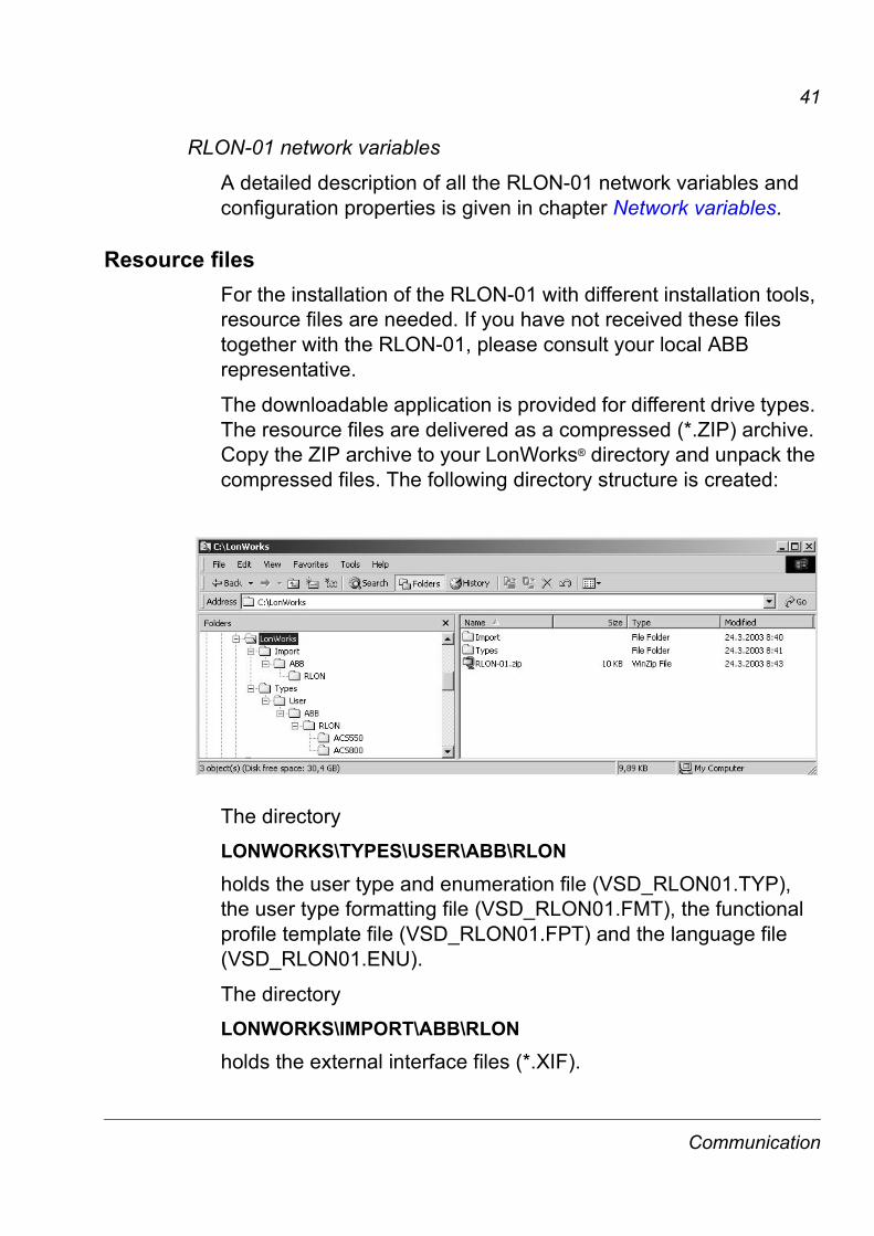
Resource filesFor the installation of the RLON-01 with different installation tools, resource files are needed. If you have not received these files together with the RLON-01, please consult your local ABB representative.
The downloadable application is provided for different drive types. The resource files are delivered as a compressed (*.ZIP) archive. Copy the ZIP archive to your LonWorks® directory and unpack the compressed files. The following directory structure is created:
The directory
LONWORKS\TYPES\USER\ABB\RLON
holds the user type and enumeration file (VSD_RLON01.TYP), the user type formatting file (VSD_RLON01.FMT), the functional profile template file (VSD_RLON01.FPT) and the language file (VSD_RLON01.ENU).
The directory
LONWORKS\IMPORT\ABB\RLON
holds the external interface files (*.XIF).
Communication
42
The directories
LONWORKS\IMPORT\ABB\RLON\ACS800LONWORKS\IMPORT\ABB\RLON\ACS550etc.
hold the external interface files (*XIF)
XIF version 2.0 (e.g. ACS800_V20.XIF)XIF version 3.1 (e.g. ACS800_V31.XIF)XIF version 4.1 (e.g. ACS800_V41.XIF)XIF version 4.4 (e.g. ACS800_V44.XIF)
The device interface (XIF) file is a standalone file that documents the device interface for a type of device. It also documents the default values for all the configuration properties on the device. The three different *XIF files are for the different versions of the LonMaker-tool. The appropriate XIF file version is chosen depending on the installation tool used.
Communication
43
Network variables
Supported input network variablesThe actual valid range of a network input variable can be smaller than the one reported in this manual, depending of the drive firmware. Typically the ACx550 discards the parameter changes, if the value coming from the fieldbus is outside the range of the drive parameter; ACS800 limits too large values to the highest value allowed.
Name Description
NviDrvSpeedStpt Low-resolution speed set point.
NviDrvSpeedScale Scaling for nviDrvSpeedStpt.
NviResetFault Input to the motor to clear the fault status in the drive.
NviEmergOverride Possibility to stop the motor in case of an emergency.
NviDigOutput Controls the state for digital output 1-8.
NviDigOutput1 Controls the state for digital output 1.
NviDigOutput2 Controls the state for digital output 2.
NviExt1Ext2Ctrl Sets the control location that should be used (Ext1/Ext2).
Network variables
44
NviDrvSpeedStptDefinition:
Network input SNVT_switch nviDrvSpeedStpt
Explanation:
Provides a low-resolution speed set point. The speed set point is the result of multiplication of nviDrvSpeedStpt and nviDrvSpeedScale. For example if the value of the nviDrvSpeedStpt is 100% and the value of the nviDrvSpeedScale is -150%, the actual speed setpoint value is -150% meaning 1.5 times nominal speed in reverse direction.
Valid range:
Default value:
The default value is AUTO (state = 0xFF). The value will be adapted at power-up and in case of not receiving an update within the specified Receive Heartbeat time. This input network variable may use the Receive Heartbeat function if the Receive Heartbeat function is set up for use. The actual drive speed also depends on nviDrvSpeedScale.
This value is transmitted immediately when its value has changed significantly, but no faster than the Minimum Send Time (nciMinOutTm) configuration value, if used.
Additionally, this network variable will also be transmitted as a heartbeat output on a regular basis as specified by the Maximum Send Time (nciSndHrtBt) configuration value.
State Value Equivalent percentage
Requested speed
0 Not used Not used STOPPED
1 0 0% 0%
1 1 to 100 1 to 100.0% 1 to 100.0%
0xFF Not used Not used AUTO (invalid)
Network variables
45
NviDrvSpeedScaleDefinition:
Network input SNVT_lev_percent nviDrvSpeedScale
Explanation:
Provides scaling for nviDrvSpeedStpt. For example if nviDrvSpeedStpt value is 100% and nviDrvSpeedScale value is -150%, then the actual speed setpoint value is -150% meaning 1.5 times the nominal speed in reverse direction.
Valid range:
-163.84% .. 163.83% (0.005% or 50 ppm)
The value 0x7FFF represents invalid data.
Default value:
Defined by nciDrvSpdScale. This value will be adopted at power-up and in case of not receiving an update within the specified Receive Heartbeat time.
NviResetFaultDefinition:
Network input SNVT_switch nviResetFault
Explanation:
Provides an input to the motor to clear the fault status in the drive.
Valid range:
On a transition from 0 to 1, this input network variable clears the fault condition in the drive. Following a fault reset, this variable should be set to '0' to enable the next reset fault.
State Value Command
0 0% Enable reset fault
1 100% Reset fault
Network variables
46
Default value:
The module will power-up in the 'Enable Reset Fault' state.
NviEmergOverrideDefinition:
Network input SNVT_hvac_emerg nviEmergOverride (HVAC Emergency Mode)
Explanation:
Provides the possibility to stop the motor in case of an emergency.
Valid range:
Default value:
EMERG_NORMAL
Setting Function
EMERG_NORMAL No emergency mode, motor control enabled.
EMERG_PRESSURIZE Not in use
EMERG_DEPRESSURIZE Not in use
EMERG_PURGE Not in use
EMERG_SHUTDOWN Emergency shutdown mode. Stops motor.
EMERG_FIRE Not in use
EMERG_NUL Not in use
Network variables
47
NviDigOutput
Note: The number of digital inputs varies between the drive types.
Definition:
Network input SNVT_state nviDigOutput
Explanation:
Controls the state for digital output 1-8.
Valid range:
Default value:
0
bit0 Sets Digital Output 1
bit1 Sets Digital Output 2
bit2 Sets Digital Output 3
bit3 Sets Digital Output 4
bit4 Sets Digital Output 5
bit5 Sets Digital Output 6
bit6 Sets Digital Output 7
bit7 Sets Digital Output 8
bit8-15 Unused
Network variables
48
NviDigOutput1
Note: For ACx550 only.
Definition:
Network input SNVT_switch nviDigOutput1
Explanation:
Controls the state for digital output 1.
Valid range:
Default value:
0
NviDigOutput2
Note: For ACx550 only.
Definition:
Network input SNVT_switch nviDigOutput2
Explanation:
Controls the state for digital output 2.
Valid range:
Default value:
0
State Value Command
0 0% Set digital output to LOW state (0).
1 100% Set digital output to HIGH state (1).
state value command
0 0% Set digital output to LOW state (0).
1 100% Set digital output to HIGH state (1).
Network variables
49
NviExt1Ext2CtrlDefinition:
Network input SNVT_switch nviExt1Ext2Ctrl
Explanation:
This input variable sets the control location that should be used (Ext1/Ext2).
Valid range:
state value command
0 0% Ext1 selected.
1 100% Ext2 selected.
Network variables
50
Supported output network variablesName Description
NvoDrvSpeed Speed of the drive as a percentage of the nominal speed.
NvoDrvCurnt Drive current in Amp
NvoDrvPwr Drive power in kilowatt
NvoDrvRunHours Total power-on time in whole hours
NvoDrvVolt Motor output voltage in Volts.
NvoSpeedActRpm Output speed in rpm
NvoDrvTemp Temperature in degrees C
NvoFreqAct Output frequency in Hz
NvoDrvStatus Status of the drive.
NvoRunning Motor running state.
NvoFaulted Information on the fault status of the drive.
NvoPidAct PID controller feedback value
NvoEmergOvrStat Feedback for the nviEmergOverride
NvoDigInput1 Status of Digital Input 1 (DI1).
NvoDigInput2 Status of Digital Input 2 (DI2).
NvoAnlgInput Status of Analog Input.
NvoParValue Data read at parameter set by nciParRead.
NvoDigIOStat State for digital output 1-8.
NvoExt1Ext2Stat Control location currently used (Ext1/Ext2).
NvoLocRemStat Control mode (Local or Remote).
NvoLastFault Latest malfunction code that has occurred.
Network variables
51
NvoDrvSpeedDefinition:
Network output SNVT_lev_percent nvoDrvSpeed
Explanation:
Provides the speed of the drive as a percentage of the nominal speed.
Valid range:
-163.84% .. 163.83% (0.005% or 50 ppm)
A value of 0x7FFF represents invalid data.
NvoDrvCurntDefinition:
Network output SNVT_amp nvoDrvCurnt
Explanation:
Drive current in Amp
Valid Range:
-3276.8 .. 3276.7 Amp (0.1 A)
A value of 0x7FFF represents invalid data.
NvoDrvPwrDefinition:
Network output SNVT_power_kilo nvoDrvPwr
Explanation:
Drive power in kilowatt
Valid range:
0 .. 6553.5 kW (0.1 kW)
A value of 0xFFFF represents invalid data.
Network variables
52
NvoDrvRunHoursDefinition:
Network output SNVT_time_hour nvoDrvRunHours
Explanation:
Total power-on time in whole hours
Valid range:
0 .. 65535 hour (1 hour)
A value of 0xFFFF represents invalid data.
NvoDrvVoltDefinition:
Network output SNVT_volt nvoDrvVolt
Explanation:
Motor output voltage in Volts.
Valid range:
-3276.8 .. 3276.7 Volt (0.1 V)
A value of 0x7FFF represents invalid data.
NvoSpeedActRpmDefinition:
Network output SNVT_count_inc nvoSpeedActRpm
Explanation:
Output speed in rpm
Valid range:
-32768 .. 32767 rpm (1 rpm)
Network variables
53
NvoDrvTempDefinition:
Network output SNVT_temp_p nvoDrvTemp
Explanation:
Temperature in degrees C
Valid range:
-274 .. 6279.5 degrees C (0.1 degrees C )
A value of 0x7FFF represents invalid data.
NvoFreqActDefinition:
Network output SNVT_freq_hz nvoFreqAct
Explanation:
Output frequency in Hz
Valid range:
0 .. 6553.5 Hz (0.1 Hz)
Network variables
54
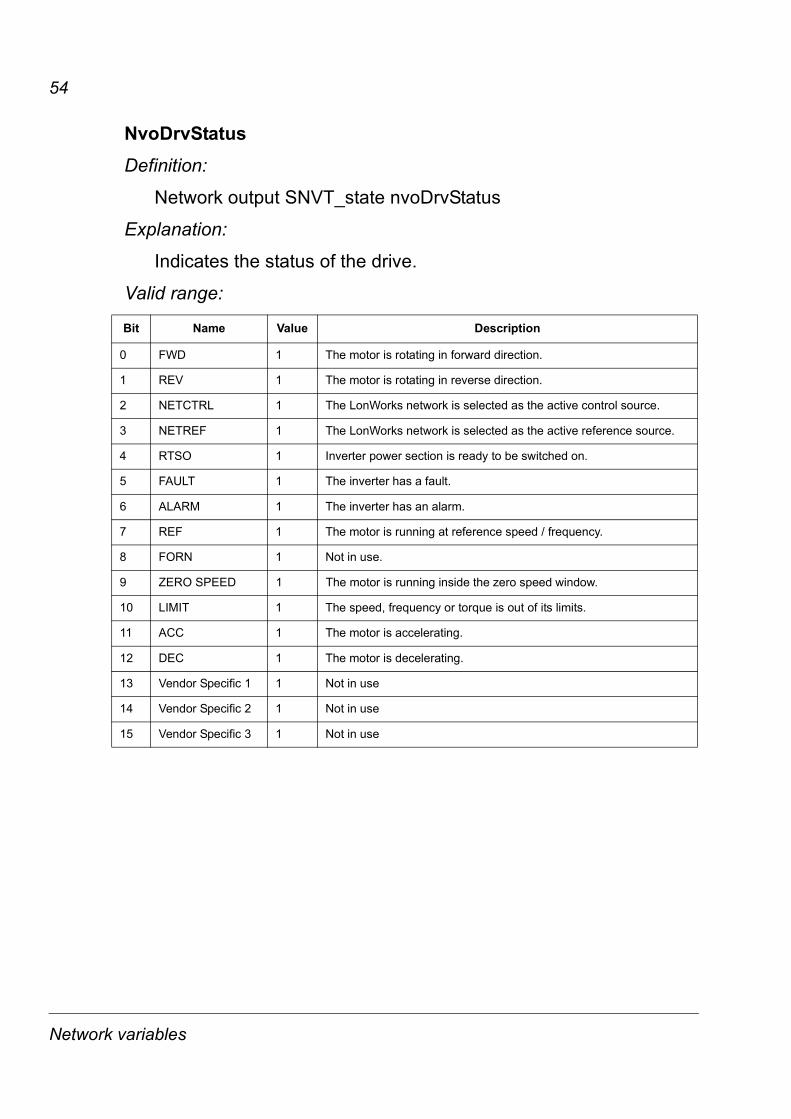
NvoDrvStatusDefinition:
Network output SNVT_state nvoDrvStatus
Explanation:
Indicates the status of the drive.
Valid range:
Bit Name Value Description
0 FWD 1 The motor is rotating in forward direction.
1 REV 1 The motor is rotating in reverse direction.
2 NETCTRL 1 The LonWorks network is selected as the active control source.
3 NETREF 1 The LonWorks network is selected as the active reference source.
4 RTSO 1 Inverter power section is ready to be switched on.
5 FAULT 1 The inverter has a fault.
6 ALARM 1 The inverter has an alarm.
7 REF 1 The motor is running at reference speed / frequency.
8 FORN 1 Not in use.
9 ZERO SPEED 1 The motor is running inside the zero speed window.
10 LIMIT 1 The speed, frequency or torque is out of its limits.
11 ACC 1 The motor is accelerating.
12 DEC 1 The motor is decelerating.
13 Vendor Specific 1 1 Not in use
14 Vendor Specific 2 1 Not in use
15 Vendor Specific 3 1 Not in use
Network variables
55
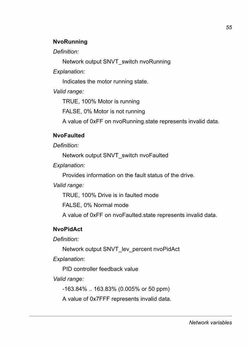
NvoRunningDefinition:
Network output SNVT_switch nvoRunning
Explanation:
Indicates the motor running state.
Valid range:
TRUE, 100% Motor is running
FALSE, 0% Motor is not running
A value of 0xFF on nvoRunning.state represents invalid data.
NvoFaultedDefinition:
Network output SNVT_switch nvoFaulted
Explanation:
Provides information on the fault status of the drive.
Valid range:
TRUE, 100% Drive is in faulted mode
FALSE, 0% Normal mode
A value of 0xFF on nvoFaulted.state represents invalid data.
NvoPidActDefinition:
Network output SNVT_lev_percent nvoPidAct
Explanation:
PID controller feedback value
Valid range:
-163.84% .. 163.83% (0.005% or 50 ppm)
A value of 0x7FFF represents invalid data.
Network variables
56
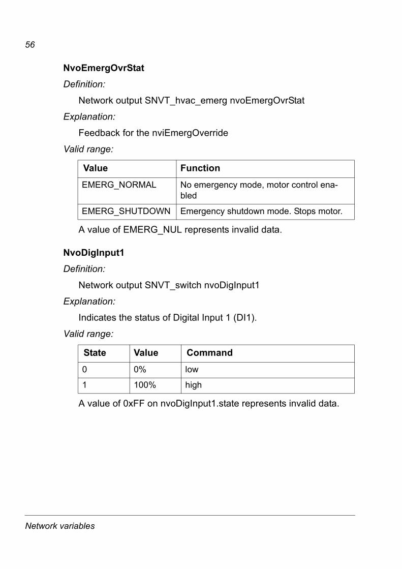
NvoEmergOvrStatDefinition:
Network output SNVT_hvac_emerg nvoEmergOvrStat
Explanation:
Feedback for the nviEmergOverride
Valid range:
A value of EMERG_NUL represents invalid data.
NvoDigInput1Definition:
Network output SNVT_switch nvoDigInput1
Explanation:
Indicates the status of Digital Input 1 (DI1).
Valid range:
A value of 0xFF on nvoDigInput1.state represents invalid data.
Value Function
EMERG_NORMAL No emergency mode, motor control ena-bled
EMERG_SHUTDOWN Emergency shutdown mode. Stops motor.
State Value Command
0 0% low
1 100% high
Network variables
57
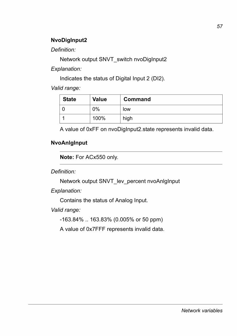
NvoDigInput2Definition:
Network output SNVT_switch nvoDigInput2
Explanation:
Indicates the status of Digital Input 2 (DI2).
Valid range:
A value of 0xFF on nvoDigInput2.state represents invalid data.
NvoAnlgInput
Note: For ACx550 only.
Definition:
Network output SNVT_lev_percent nvoAnlgInput
Explanation:
Contains the status of Analog Input.
Valid range:
-163.84% .. 163.83% (0.005% or 50 ppm)
A value of 0x7FFF represents invalid data.
State Value Command
0 0% low
1 100% high
Network variables
58
NvoParValueDefinition:
Network output SNVT_count nvoParValue
Explanation:
Contains the data read at parameter set by nciParRead.
Valid range:
0 .. 65535
A value of 0xFFFF represents invalid data.
NvoDigIOStat
Note: The number of digital inputs and outputs varies between the drive types.
Definition:
Network output SNVT_switch nvoDigIOStat.
Explanation:
This output variable contains the state for digital inputs 1�8 and digital outputs 1�8.
Network variables
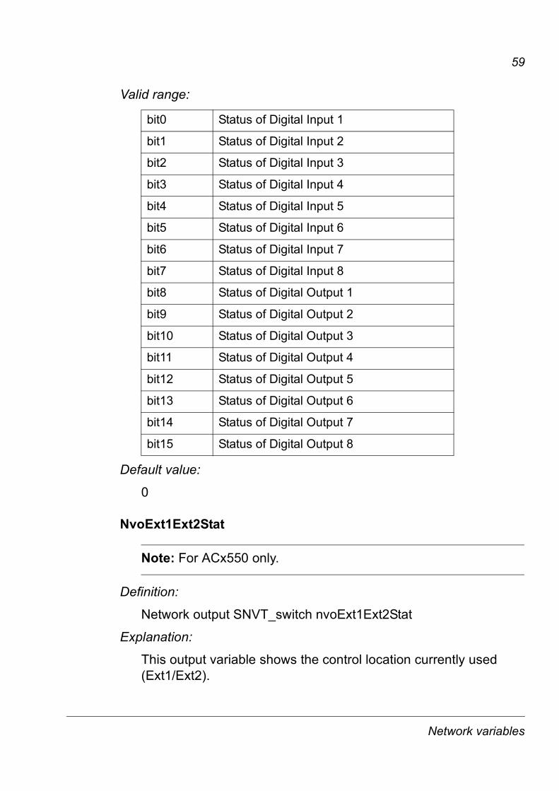
59
Valid range:
Default value:
0
NvoExt1Ext2Stat
Note: For ACx550 only.
Definition:
Network output SNVT_switch nvoExt1Ext2Stat
Explanation:
This output variable shows the control location currently used (Ext1/Ext2).
bit0 Status of Digital Input 1
bit1 Status of Digital Input 2
bit2 Status of Digital Input 3
bit3 Status of Digital Input 4
bit4 Status of Digital Input 5
bit5 Status of Digital Input 6
bit6 Status of Digital Input 7
bit7 Status of Digital Input 8
bit8 Status of Digital Output 1
bit9 Status of Digital Output 2
bit10 Status of Digital Output 3
bit11 Status of Digital Output 4
bit12 Status of Digital Output 5
bit13 Status of Digital Output 6
bit14 Status of Digital Output 7
bit15 Status of Digital Output 8
Network variables
60
Valid range:
A value of 0xFF on nvoExt1Ext2Stat represents invalid data.
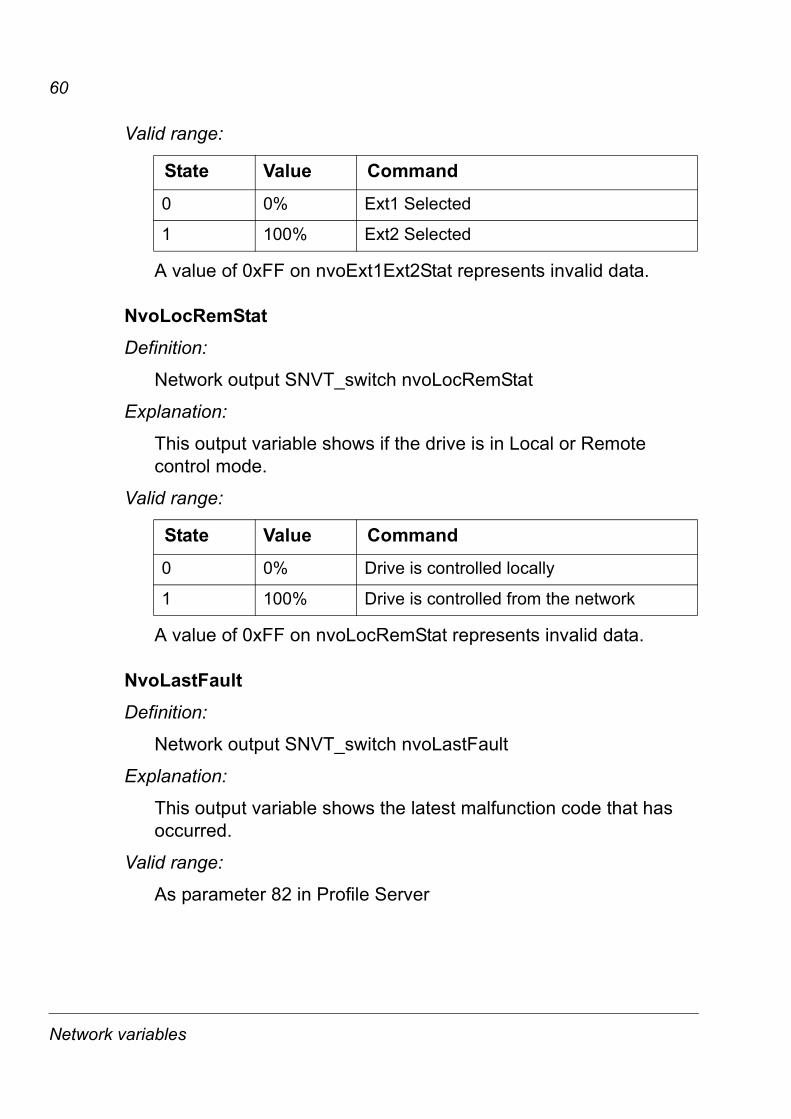
NvoLocRemStatDefinition:
Network output SNVT_switch nvoLocRemStat
Explanation:
This output variable shows if the drive is in Local or Remote control mode.
Valid range:
A value of 0xFF on nvoLocRemStat represents invalid data.
NvoLastFaultDefinition:
Network output SNVT_switch nvoLastFault
Explanation:
This output variable shows the latest malfunction code that has occurred.
Valid range:
As parameter 82 in Profile Server
State Value Command
0 0% Ext1 Selected
1 100% Ext2 Selected
State Value Command
0 0% Drive is controlled locally
1 100% Drive is controlled from the network
Network variables
61
Supported network configuration propertiesAll configuration properties are defined as configuration network variables in this product. Some network management tools will show these variables as SCPT/UCPT configuration properties and some as network configuration variables. The difference in the network management tools only affects the presentation of the variables but not their functionality.
Name Description
SCPTmaxSendTime / nciSndHrtBt
Maximum send time for the variable nvoDrvSpeed.
SCPTmaxRcvTime / nciRcvHrtBt
Defines the maximum allowed update interval for input network variables nviDrvSpeedStpt and nviDrvSpdScale.
SCPTminSendTime / nciMinOutTm
Defines the minimum wait time before the network output variables can be propagated (resent).
SCPTnomRPM / nciNmlSpeed
Sets the nominal motor speed.
SCPTnomFreq / nciNmlFreq
Sets the nominal frequency of the motor.
SCPTminSetpoint / nciMinSpeed
Defines the minimum speed of the motor as a percentage of the nominal speed defined by the Nominal Speed (nciNmlSpeed) configuration value.
SCPTmaxSetpoint / nciMaxSpeed
Defines the maximum motor speed.
SCPTrampUpTm / nciRampUpTm
Sets the ramp up time of the drive.
SCPTrampDownTm / nciRampDownTm
Sets the ramp down time of the drive.
SCPTlocation / nciLocation
Physical location of the node.
SCPTdefScale / nciDrvSpdScl
Default value for nviDrvSpeedScale
Network variables
62
SCPTmaxSendTime / nciSndHrtBtDefinition:
Network config input SNVT_time_sec nciSndHrtBt
Explanation:
Provides the maximum send time for the variable nvoDrvSpeed.
Valid range:
0 .. 6553.5 sec (0.1 sec)
The value 0xFFFF represents invalid data.
Default value:
0 (disabled)
UCPTstopMode / nciStopMode
Selects between coast and ramp stop.
UCPTstopLevel / nciStopLevel
Stop level value in ramp stop mode.
UCPTpidGain / nciPidGain
PID controller gain in percentage.
UCPTpidIntTime / nciPIDIntTime
PID controller integration time in seconds.
UCPTpidDerTime / nciPidDerTime
PID controller derivation time in seconds.
UCPTparValue / nciParValue
Value input for the user selected parameter nciParWrite.
UCPTparRead / nciParRead
Chooses the parameter value to be read from the drive.
UCPTparWrite / nciParWrite
Defines the parameter value to be written to the drive.
Network variables
63
SCPTmaxRcvTime / nciRcvHrtBtDefinition:
Network config input SNVT_time_sec nciRcvHrtBt
Explanation:
Defines the maximum allowed update interval for input network variables nviDrvSpeedStpt and nviDrvSpdScale. A timeout occurs, if the set update time is exceeded.
Valid range:
0 .. 6553.5 sec (0.1 sec)
The value 0xFFFF represents invalid data.
The value 0 disables the Receive Heartbeat mechanism.
Default value:
0 (disabled)
SCPTminSendTime / nciMinOutTmDefinition:
Network config input SNVT_time_sec nciMinOutTm
Explanation:
Defines the minimum wait time before the network output variables can be propagated (resent).
Valid range:
0 .. 6553.4 sec (0.1 sec)
The value 0xFFFF represents invalid data.
The value 0 disables transmission limiting.
Default value:
0 (disabled)
Network variables
64
SCPTnomRPM / nciNmlSpeedDefinition:
Network config input SNVT_rpm nciNmlSpeed
Explanation:
Is used to set the nominal motor speed.
Valid range:
0 .. 65535 rpm (1 rpm)
The value 0xFFFF represents invalid data.
Default value:
Read from the drive. Otherwise 0.
SCPTnomFreq / nciNmlFreqDefinition:
Network config input SNVT_freq_hz nciNmlFreq
Explanation:
Is used to set the nominal frequency of the motor.
Valid range:
0 .. 6553.5 Hz (0.1 Hz)
Default value:
Read from the drive. Otherwise 0.
Network variables
65
SCPTminSetpoint / nciMinSpeedDefinition:
Network config input SNVT_lev_percent nciMinSpeed
Explanation:
Defines the minimum speed of the motor as a percentage of the nominal speed defined by the Nominal Speed (nciNmlSpeed) configuration value.
The value of the minimum speed must be defined so that
-163.0 < minimum speed < maximum speed < 163.0
Valid range:
-163.84% .. 163.83% (0.005% or 50 ppm)
The value 0x7FFF represents invalid data.
Default value:
Read from the drive. Otherwise 0.
SCPTmaxSetpoint / nciMaxSpeedDefinition:
Network config input SNVT_lev_percent nciMaxSpeed
Explanation:
Is used to define the maximum motor speed. The value is entered as a percent of nominal speed, as defined by the Nominal Speed (nciNmlSpeed) configuration value.
The value of the maximum speed must be defined so that
-163.0 < minimum speed < maximum speed < 163.0
Valid range:
-163.84% .. 163.83% (0.005% or 50 ppm)
The value 0x7FFF represents invalid data.
Default value:
Read from the drive. Otherwise 0.
Network variables
66
SCPTrampUpTm / nciRampUpTmDefinition:
Network config input SNVT_time_sec nciRampUpTm
Explanation:
Is used to provide to set the ramp up time of the drive.
Valid range:
0 .. 6553.5 sec (0.1 sec)
The value 0xFFFF represents invalid data.
Default value:
Read from the drive. Otherwise 0.
SCPTrampDownTm / nciRampDownTmDefinition:
Network config input SNVT_time_sec nciRampUpTm
Explanation:
Is used to provide to set the ramp down time of the drive.
Valid range:
0 .. 6553.5 sec (0.1 sec)
The value 0xFFFF represents invalid data.
Default value:
Read from the drive. Otherwise 0
Network variables
67
SCPTlocation / nciLocationDefinition:
Network config input SNVT_str_asc nciLocation
Explanation:
Location Label: used to provide physical location of the node.
Valid range:
31 characters
Default value:
empty spaces
SCPTdefScale / nciDrvSpdSclDefinition:
Network config input SNVT_lev_percent nciDrvSpdScl
Explanation:
Default value for nviDrvSpeedScale
Valid range:
-163.84% .. 163.83% (0.005% or 50 ppm)
The value 0x7FFF represents invalid data.
Default value:
0
Network variables
68
UCPTstopMode / nciStopModeDefinition:
Network config input SNVT_switch nciStopMode
UCPT type index: 6
Explanation:
Is used to select between coast and ramp stop.
Valid range:
OFF = COAST, ON = RAMP
Default value:
COAST
UCPTstopLevel / nciStopLevelDefinition:
Network config input SNVT_lev_percent nciStopLevel
UCPT type index: 7
Explanation:
Stop level value in ramp stop mode. When the speed of the drive reaches this level, a coast stop is performed. The value is relative to nvoDrvSpeed i.e. the value of 5% corresponds to nvoDrvSpeed value 5%.
Valid range:
Valid range 5-100%
-163.84% .. 163.83% (0.005% or 50 ppm)
The value 0x7FFF represents invalid data.
Default value:
5%.
Network variables
69
UCPTpidGain / nciPidGainDefinition:
Network config input SNVT_lev_percent nciPidGain
UCPT type index: 2
Explanation:
PID controller gain in percentage.
Valid Range:
-163.84% .. 163.83% (0.005% or 50 ppm)
The value 0x7FFF represents invalid data.
Default Value:
Read from the drive. Otherwise 0.
UCPTpidIntTime / nciPIDIntTimeDefinition:
Network config input SNVT_time_sec nciPidIntTime
UCPT type index: 3
Explanation:
PID controller integration time in seconds.
Valid range:
0 .. 6553.5 sec (0.1 sec)
The value 0xFFFF represents invalid data.
Default value:
Read from the drive. Otherwise 0.
Network variables
70
UCPTpidDerTime / nciPidDerTimeDefinition:
Network config input SNVT_time_sec nciPidDerTime
UCPT type index: 4
Explanation:
PID controller derivation time in seconds.
Valid range:
0 .. 6553.5 sec (0.1 sec)
The value 0xFFFF represents invalid data.
Default value:
Read from the drive. Otherwise 0.
UCPTparValue / nciParValueDefinition:
Network config input SNVT_count_inc nciParValue
UCPT type index: 9
Explanation:
This input network variable is used as a value input for the user selected parameter nciParWrite.
Valid range:
-32768 .. 32767
Default value:
0
Network variables
71
UCPTparRead / nciParReadDefinition:
Network config input SNVT_count nciParRead
UCPT type index: 10
Explanation:
Chooses the parameter value to be read from the drive.
Valid range:
0 .. 65535
Default value:
0
UCPTparWrite / nciParWriteDefinition:
Network config input SNVT_count nciParWrite
UCPT type index: 11
Explanation:
Defines the parameter value to be written to the drive.
Valid range:
0 .. 65535
Default value:
0
Network variables

72
Network variables
73
Fault tracing
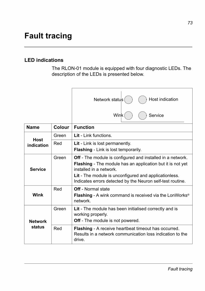
LED indicationsThe RLON-01 module is equipped with four diagnostic LEDs. The description of the LEDs is presented below.
Name Colour Function
Host indication
Green Lit - Link functions.
Red Lit - Link is lost permanently.Flashing - Link is lost temporarily.
Service
Green Off - The module is configured and installed in a network.Flashing - The module has an application but it is not yet installed in a network.Lit - The module is unconfigured and applicationless. Indicates errors detected by the Neuron self-test routine.
WinkRed Off - Normal state
Flashing - A wink command is received via the LonWorks® network.
Network status
Green Lit - The module has been initialised correctly and is working properly.Off - The module is not powered.
Red Flashing - A receive heartbeat timeout has occurred. Results in a network communication loss indication to the drive.
ServiceWink
Network status Host indication
Fault tracing

74
Fault tracing
75
Technical data
RLON-01Enclosure:
Mounting: Into its option slot inside the drive
Degree of protection: IP 20
Ambient conditions: The applicable ambient conditions specified for the drive in its Hardware Manual are in effect.
Connectors:� 34-pin parallel bus connector
� 5-pole screw type connector (detachable)
95 m
m
34 mm
20 mm
62 mm
Technical data
76
Current consumption:� 160 mA maximum (5 V), supplied by the control board of the
drive.
General:� Estimated minimum lifetime 100 000 h
� All materials are UL/CSA approved
� Complies with EMC Standards EN 50081-2 and EN 50082-2.
LONWORKS® networkRLON-01 compatible devices:
All devices equipped with FT-X1 and FTT-10A compatible transceivers.
Size of the network: 32385 nodes divided into 127 nodes / subnet with 255 subnets /domain.
Medium: � Special LON® cable
� Termination: 105 Ω / 52.5 Ω, depending on the network topology. See Bus termination.
� Cable specifications: See the following tables
Technical data
77
.
LONWORKS® network cable specifications
Control /signallinggrade 16 AWG (1.3 mm)
General purpose grade 16 AWG (1.3 mm)
Data grade level 4 22 AWG (0.65 mm)
JY (St) Y 2×2×0.820.4 AWG(0.8 mm)
Max. DC resistance at 20 °C loop 28.2 Ω/km 28.2 Ω/km 118 Ω/km 74.0 Ω/km
Max. DC resistance unbalance 5%
Max. mutual capacitance of a pair
58 nF/km 74 nF/km 56 nF/km 100 nF/km
Max. pair-to-ground capacitance unbalance
3.28 nF/km
Nominal impedance 95 Ω at
1.0 MHz100 Ω at 1.0 MHz
102 Ω ±15% at 772 kHz
100 Ω ±15% at 1, 4, 8, 10, 16 and 20 MHz
Max. attenuation at 20 °C
15 dB/km at 772 kHz18 dB/km at 1.0 MHz36 dB/km at 4.0 MHz49 dB/km at 8.0 MHz56 dB/km at 10.0 MHz72 dB/km at 16.0 MHz79 dB/km at 20.0 MHz
Pair twists per metre
20 (nominal)
20 (minimum)
5 (minimum)
Technical data
78
Cable parameters single twisted pair stranded 19/29 unshielded Tefzel Insulation & Jacket High 150 °C max.
single twisted pair stranded 19/29 unshielded PVC Insulation & Jacket Medium80 °C max.
twisted pair, single or multiple typically solid and unshielded
wire pair:red/black per DIN VDE 0815 4-wire helical twist solid shielded
LONWORKS® network cable specifications
Control /signallinggrade 16 AWG (1.3 mm)
General purpose grade 16 AWG (1.3 mm)
Data grade level 4 22 AWG (0.65 mm)
JY (St) Y 2×2×0.820.4 AWG(0.8 mm)
Technical data
79
.
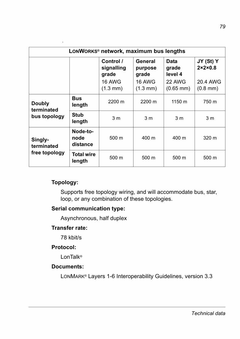
Topology: Supports free topology wiring, and will accommodate bus, star, loop, or any combination of these topologies.
Serial communication type: Asynchronous, half duplex
Transfer rate: 78 kbit/s
Protocol: LonTalk®
Documents: LONMARK® Layers 1-6 Interoperability Guidelines, version 3.3
LONWORKS® network, maximum bus lengths
Control / signalling grade 16 AWG(1.3 mm)
General purpose grade 16 AWG (1.3 mm)
Data grade level 4 22 AWG(0.65 mm)
JY (St) Y 2×2×0.8 20.4 AWG(0.8 mm)
Doubly terminatedbus topology
Bus length 2200 m 2200 m 1150 m 750 m
Stub length 3 m 3 m 3 m 3 m
Singly-terminated free topology
Node-to-node distance
500 m 400 m 400 m 320 m
Total wire length 500 m 500 m 500 m 500 m
Technical data

80
Technical data

ABB OyAC DrivesP.O. Box 184FI-00381 HELSINKIFINLANDTelephone +358 10 22 11Fax +358 10 22 22681Internet http://www.abb.com
ABB Inc.Automation TechnologiesDrives & Motors16250 West Glendale DriveNew Berlin, WI 53151USATelephone 262 785-3200
800-HELP-365Fax 262 780-5135
ABB Beijing Drive Systems Co. Ltd.No. 1, Block D, A-10 Jiuxian-qiao BeiluChaoyang DistrictBeijing, P.R. China, 100015Telephone+86 10 5821 7788Fax +86 10 5821 7618Internet http://www.abb.com
3AFE
6479
8693
RE
V B
EN
EFF
EC
TIV
E: 0
7.12
.200
6