Enhancing System Level Performance of Third Generation ...
126
126 JYVÄSKYLÄ STUDIES IN COMPUTING Enhancing System Level Performance of Third Generation Cellular Networks Through VoIP and MBMS Services Kari Aho
Transcript of Enhancing System Level Performance of Third Generation ...
126J Y V Ä S K Y L Ä S T U D I E S I N C O M P U T I N G
Enhancing System Level Performance of Third Generation Cellular Networks
Through VoIP and MBMS Services
Kari Aho
JYVÄSKYLÄ STUDIES IN COMPUTING 126
Kari Aho
UNIVERSITY OF
JYVÄSKYLÄ 2010
Esitetään Jyväskylän yliopiston informaatioteknologian tiedekunnan suostumuksellajulkisesti tarkastettavaksi yliopiston Agora-rakennuksen auditoriossa 2
joulukuun 17. päivänä 2010 kello 12.
Academic dissertation to be publicly discussed, by permission ofthe Faculty of Information Technology of the University of Jyväskylä,
in the Agora building, auditorium 2, on December 17, 2010 at 12 o'clock noon.
JYVÄSKYLÄ
Third Generation Cellular Networksthrough VoIP and MBMS Services
Enhancing System Level Performance of
Enhancing System Level Performance ofThird Generation Cellular Networks
through VoIP and MBMS Services
JYVÄSKYLÄ STUDIES IN COMPUTING 126
JYVÄSKYLÄ 2010
Enhancing System Level Performance of
UNIVERSITY OF JYVÄSKYLÄ
Kari Aho
Third Generation Cellular Networksthrough VoIP and MBMS Services
Copyright © , by University of Jyväskylä
URN:ISBN:978-951-39-4143-7ISBN 978-951-39-4143-7 (PDF)
ISBN 978-951-39-4127-7 (nid.)ISSN 1456-5390
2010
Jyväskylä University Printing House, Jyväskylä 2010
Editor Timo Männikkö Department of Mathematical Information Technology, University of Jyväskylä Pekka Olsbo, Sini Rainivaara Publishing Unit, University Library of Jyväskylä
ABSTRACT
Aho, KariEnhancing System Level Performance of Third Generation Cellular Networksthrough VoIP and MBMS ServicesJyväskylä: University of Jyväskylä, 2010, 121 p.(+included articles)(Jyväskylä Studies in ComputingISSN 1456-5390; 126)ISBN 978-951-39-4127-7 (nid.), 978-951-39-4143-7 (PDF)Finnish summaryDiss.
The purpose of this thesis is to address variety of performance enhancementsand configurations in terms of 3G/3.5G cellular networks. Multimedia BroadcastMulticast Service (MBMS) and Voice over IP (VoIP) are used to benchmark differentfeatures as they are undeniably key concepts also in the wireless cellular networksand thus securing their performance can be considered as critical. From practicalperspective, wireless networks set a very strict environment for different servicesthrough additional delays, packet loss, jitter, corruption and so forth. This thesisaddresses those challenges by evaluating variety of diversity options, mobilityperformance aspects and robustness, battery saving opportunities, interferencecoordination and finally applicability of dual carrier. Studies are conducted withthe help of time driven cellular system simulators where, e.g., fading, propaga-tion and radio management functionalities are explicitly taken into account.
Keywords: Mobility, Handover, Receive Diversity, Transmit Diversity, Macro Di-versity, Interference Coordination, Dual Carrier, Capacity, Battery Sav-ings, Quality of Service, MBMS, VoIP, HSDPA, HSUPA.
Author Kari AhoDepartment of Mathematical Information TechnologyUniversity of JyväskyläFinland
Supervisor Professor Tapani RistaniemiDepartment of Mathematical Information TechnologyUniversity of JyväskyläFinland
Reviewers Associate Professor, Dr. Peter ChongDivision of Communication EngineeringSchool of Electrical & Electronic EngineeringNanyang Technological UniversitySingapore
Assistant Professor, Dr. Zekeriya UykanNokia Siemens NetworksFinlandElectronics and CommunicationsEngineering DepartmentDogus UniversityTurkey
Opponent Professor Marcos KatzCentre for Wireless Communications &Telecommunications LaboratoryUniversity of OuluFinland
ACKNOWLEDGEMENTS
The studies related to this thesis are done in co-operation with the University ofJyväskylä, Magister Solutions Ltd., Nokia Research Center and Nokia SiemensNetworks. I want to express my gratitude to all of my co-workers and colleagueswho have helped, encouraged and supported me along the way. If I would startto list names it would definitely get unjust as there are so many of you and Iwould hate to have forgotten someone. I hope I have expressed my gratitudealso along the way and I will definitely do so also in the future. Having saidthat, there are actually two people I have to give special thanks to because with-out them I would not have had the privilege to work alongside with you. Thosepeople are my supervising Professor Tapani Ristaniemi and my instructor Ph.D.Janne Kurjenniemi and I would like to once again thank them for their contin-uous guidance throughout this process and more importantly for giving me theopportunity to start working on this thesis, studies and project related to it.
I would also like to rise up and thank non-profitable foundations who haveprovided extremely valuable funding to complete this thesis. In general, thatkind of funding is imperative to support academic research and to keep Finnishknow-how one of the most valued in the world. Foundations that have supportedthe competition of this thesis are listed in the following by their Finnish names inalphabetical order:
• Nokia säätiö,
• Suomen akatemia,
• Tekniikan edistämissäätiö,
• TeliaSonera Finland Oyj:n tutkimus- ja koulutussäätiö,
• Ulla Tuomisen säätiö.
Finally, yet importantly, I would like to express my sincerest gratitude to my fam-ily and all of my friends for so many things ranging all the way from the momentswe have shared to completing this thesis. I hope and believe that all of you knowwho you are and you probably also know that I can never thank you enough. So,once more, thank you from the bottom of my heart. Kiitos.
ACRONYMS
1G First Generation
1Rx One Receive Antenna
2G Second Generation
2Rx Two Receive Antennas
3G Third Generation
3GPP Third Generation Partnership Project
ACM Association for Computing Machinery
AMR-WB Adaptive Multi-Rate - Wideband
AS Active Set
AVI Actual Value Interface
BCH Broadcast Channel
BER Bit Error Rate
BLER Block Error Rate
BM-SC Broadcast-Multicast Service Centre
BS Base Station
BSC Base Station Controller
C1 Carrier 1
C2 Carrier 2
C/I Carrier to Interference Ratio
CAPEX Capital Expenditure
CBR Constant Bit Rate
CBS Cell Broadcast Service
CDMA Code Division Multiple Access
CPICH Common Pilot Channel
CSCF Call Session Control Function
CL Closed Loop
CN Core Network
Codec Coder Decoder
CPC Continuous Packet Connectivity
CPCH Uplink Common Packet Channel
CS Circuit Switched
CS Combining Set
CRC Cyclic Redundancy Check
DC Dual Carrier / Dual Cell
DCCH Dedicated Control Channel
DCH Dedicated Channel
DSCH Dedicated Shared Channel
DSSS Direct Sequence Spread Spectrum
DTCH Dedicated Traffic Channel
DTX Discontinuous Transmission
DL Downlink
DPCCH Dedicated Physical Control Channel
DPDCH Dedicated Physical Data Channel
DRX Discontinuous Reception
Eb/No Energy per Bit to Noise Ratio
Es/No Energy per Symbol to Noise Ratio
Ec/Ior Energy per Chip to Interference Ratio
E-AGCH E-DCH Absolute Grant Channel
E-DCH Enhanced Dedicated Channel
E-DPCCH Enhanced Dedicated Physical Control Channel
E-DPDCH Enhanced Dedicated Physical Data Channel
E-HICH E-DCH HARQ Indicator Channel
E-RGCH E-DCH Relative Grant Channel
E-TFCI Enhanced Transport Format Combination Indicator
FACH Forward Access Channel
FER Frame Error Rate
FO First Order
GERAN GSM/EDGE Radio Access Network
GGSN Gateway GPRS Support Node
GPRS General Packet Radio Service
GSTN General Switched Telephony Network
GSM Global System for Mobile Communications
HARQ Hybrid Automatic Repeat Request
HLR Home Location Register
HO Handover
HoL Head-of-Line
HS-DSCH High Speed Downlink Shared Channel
HS-SCCH High Speed Common Control Channel
HSDPA High Speed Downlink Packet Access
HSPA High Speed Packet Access
HSS Home Subscriber Server
HSUPA High Speed Uplink Packet Access
I-CSCF Interrogating Call Session Control Function
IC Interference Coordination
IEEE Institute of Electrical and Electronics Engineers
IETF Internet Engineering Task Force
ILPC Innerloop Power Control
IMS IP Multimedia Subsystem
IP Internet Protocol
IP-MS IP Multicast Service
IR Initialization and Refresh
ISD Inter-site Distance
ITU International Telecommunication Union
L1 Layer 1
LA Link Adaptation
LTE Long Term Evolution
LMMSE Linear Minimum Mean Squared Error
MAC Medium Access Control
MBMS Multimedia Broadcast Multicast Service
MCCH MBMS Control Channel
MEGACO Media Gateway Control Protocol
MGCF Media Gateway Control Function
MGW Media Gateway
MIMO Multiple Inputs Multiple Outputs
MRC Maximum Ratio Combining
MSCH MBMS Scheduling Channel
MTCH MBMS Traffic Channel
Node-B Base Station
NMT Nordic Mobile Telephone
NST Non-Scheduled Transmissions
OL Open Loop
OLPC Outerloop Power Control
OPEX Operating Expense
P-CSCF Proxy Call Session Control Function
p-t-m point-to-multipoint
p-t-p point-to-point
PA Power Amplifier
PC Power Control
PCH Paging Channel
PedA Pedestrian A (channel profile)
PDCP Packet Data Convergence Protocol
PDU Protocol Data Unit
PF Proportional Fair
PG Processing Gain
PHY Physical Layer
PS Packet Switched
PSTN Public Switched Telephone Network
QoS Quality of Service
RACH Random Access Channel
Rel’5 Release 5
Rel’6 Release 6
Rel’7 Release 7
Rel’8 Release 8
Rel’9 Release 9
Rel’99 Release 99
RFC Request for Comments
RLC Radio Link Control
RNC Radio Network Controller
ROCH Robust Header Compression
RoT Rise over Thermal (RoT)
RR Round Robin
RRM Radio Resource Management
RTCP Real-time Transport Control Protocol
RTP Real-time Transport Protocol
RTT Round-trip time
Rx Receive
S-CCPCH Secondary Common Control Physical Channel
S-CSCF Serving Call Session Control Function
SCS Scheduling Candidate Set
SDP Session Description Protocol
SGSN Serving GPRS Support Node
SID Silence Indicator Frame
SIP Session Initiation Protocol
SINR Signal to Interference and Noise Ratio
SMS Short Message Service
SO Second Order
SRB Signaling Radio Bearer
SSRC Synchronization Source
STTD Space Time Transmit Diversity
TTI Transmission Time Interval
TU Typical Urban
Tx Transmit
UAC User Agent Client
UAS User Agent Server
UE User Equipment
UL Uplink
UTMS Universal Mobile Telecommunications System
UTRAN UMTS Terrestrial Radio Access Network
VehA Vehicular A (channel profile)
VoIP Voice over IP
WA Wrap-Around
WCDMA Wideband Code Division Multiple Access
WLAN Wireless Local Area Network
LIST OF FIGURES
FIGURE 1 UMTS Architecture ............................................................... 31FIGURE 2 CDMA Principle ................................................................... 31FIGURE 3 Example of Signal Spreading and Despreading, [45]................. 33FIGURE 4 Example of Radio Signal Propagation ..................................... 33FIGURE 5 Example of Constructive (left hand side) and Destructive (right
hand side) Addition .............................................................. 35FIGURE 6 Example of Fast Fading Process.............................................. 35FIGURE 7 Principle of Maximum Ratio Combining Within the Rake Re-
ceiver [45] ............................................................................ 36FIGURE 8 Selective Combining ............................................................. 37FIGURE 9 Soft Combining .................................................................... 38FIGURE 10 Power Control in WCDMA.................................................... 39FIGURE 11 Soft and Softer Handover Procedure....................................... 40FIGURE 12 Mapping of WCDMA/HSPA Transport Channels to Physical
Channels, [6] ........................................................................ 42FIGURE 13 Offset with HSDPA Channels................................................. 44FIGURE 14 HSUPA Channels.................................................................. 45FIGURE 15 Rel’99 Retransmissions Versus Fast Retransmissions in HSPA ... 45FIGURE 16 HSPA Retransmissions on Protocol Level ................................ 46FIGURE 17 HSUPA Code Division Multiplexing Procedure and an Exam-
ple of Predicted RoT (without interference) After Scheduling.... 50FIGURE 18 HSUPA Time Division Multiplexing Procedure and an Exam-
ple of Predicted RoT (without interference) After Scheduling.... 50FIGURE 19 HSUPA CDM/TDM Procedure and an Example of Predicted
RoT (without interference) After Scheduling ........................... 51FIGURE 20 HSDPA Hard Handover ........................................................ 52FIGURE 21 HSUPA Soft Handover .......................................................... 53FIGURE 22 Example of VoIP UL Traffic with Different TTIs and ideal UL
DTX..................................................................................... 54FIGURE 23 Uplink Discontinuous Transmission ....................................... 55FIGURE 24 Example of DRX Operation.................................................... 56FIGURE 25 Illustration of Interference Coordination ................................. 57FIGURE 26 Example of Dual Carrier Operation ........................................ 58FIGURE 27 Different Ways to Deliver Data with MBMS............................. 61FIGURE 28 Basic Structure of MBMS Multicast Service Provision [11] ......... 62FIGURE 29 Basic Structure of MBMS Broadcast Service Provision [11] ........ 62FIGURE 30 Timeline Example of MBMS Multicast Service Provision, [11] ... 64FIGURE 31 MBMS Architecture; Reference Model, [11] ............................. 65FIGURE 32 Protocol Stack for MBMS Traffic Channel, [9]........................... 66FIGURE 33 Protocol Stack for MBMS Control Channel, [9]......................... 66FIGURE 34 Simplified UTRAN MAC Architecture with Logical MBMS Chan-
nels, [9] ................................................................................ 67
FIGURE 35 E-Model Rating as a Function of Mouth-to-ear Delay [ms], [61] . 71FIGURE 36 SIP Architecture.................................................................... 73FIGURE 37 RTP Frame Structure ............................................................. 74FIGURE 38 ROCH State Transitions ......................................................... 76FIGURE 39 Example of IMS System, [46] .................................................. 77FIGURE 40 IMS Architecture Overview, [38]............................................. 77FIGURE 41 Common IMS Core Overview, [38] ......................................... 78FIGURE 42 Simulation Flow ................................................................... 81FIGURE 43 Example of VoIP Traffic Model ............................................... 83FIGURE 44 Data Flow for HSDPA, simplified from [8]............................... 85FIGURE 45 Data Flow for HSUPA, simplified from [4]............................... 85FIGURE 46 Simulation Scenario with 21 Cells and Wrap-around ................ 88FIGURE 47 Simulation Scenario with 57 Cells ........................................... 88FIGURE 48 Simulation Scenario with 18 Cells and no Wrap-around............ 88FIGURE 49 Non-regular Simulation Scenario............................................ 89FIGURE 50 Manhattan Simulation Scenarios, [21] ..................................... 90FIGURE 51 VoIP over HSDPA 95 % Outage Level Comparison with Dif-
ferent Velocities .................................................................... 94FIGURE 52 VoIP over HSDPA 95 % Outage Level Comparison with Dif-
ferent Delays ........................................................................ 95FIGURE 53 Quasi-static Simulator Confidence Analysis Results ................. 111
LIST OF TABLES
TABLE 1 Functionality of Codes in WCDMA, [45]........................... 32TABLE 2 System Simulator Classification and Main Attributes ......... 80TABLE 3 General VoIP Assumptions.............................................. 83TABLE 4 Vehicular A Channel, [60]................................................ 90TABLE 5 Modified Vehicular A Channel......................................... 91TABLE 6 Simulation Parameters for MBMS Reliability Analysis ....... 105TABLE 7 Satisfied Users with Different Seed Values, BLER < 10 % .... 107TABLE 8 Satisfied Users with Different Seed Values, BLER < 1 %...... 108TABLE 9 Required Ec/Ior for 95 % Coverage with Different Seeds .... 109TABLE 10 Statistical Confidence on Satisfied Users, BLER < 10 %....... 109TABLE 11 Statistical Confidence on Satisfied Users, BLER < 1 % ........ 110TABLE 12 Statistical Confidence on 95 % Coverage Level .................. 110TABLE 13 Main Simulation Parameters for Statistical Analysis of VoIP
Simulations.................................................................... 111TABLE 14 VoIP over HSDPA Outage Level with Different Seeds ........ 112TABLE 15 VoIP over HSDPA 95 % Outage Level with Different Seeds. 113TABLE 16 VoIP over HSDPA 95 % Outage Level with Different Sim-
ulation Lengths .............................................................. 113TABLE 17 Statistical Confidence on VoIP over HSDPA Outage Level .. 113TABLE 18 Statistical Confidence on 95 % VoIP over HSDPA Outage
Level ............................................................................. 114TABLE 19 Main Simulation Parameters for Confidence Analysis on
Quasi-static Simulations.................................................. 114TABLE 20 Statistical Confidence on Quasi-static Simulations ............. 114
CONTENTS
ABSTRACTACKNOWLEDGEMENTSACRONYMSLIST OF FIGURESLIST OF TABLESCONTENTSLIST OF INCLUDED ARTICLES
1 INTRODUCTION ............................................................................ 211.1 Research Problem ..................................................................... 221.2 Related Studies......................................................................... 25
1.2.1 Multimedia Broadcast Multicast Service .......................... 251.2.2 Voice over IP ................................................................. 261.2.3 Interference Coordination............................................... 281.2.4 Dual Carrier HSUPA...................................................... 28
1.3 Other Articles........................................................................... 29
2 WIDEBAND CODE DIVISION MULTIPLE ACCESS ........................... 302.1 Radio Access Network Architecture ........................................... 302.2 Introduction to WCDMA .......................................................... 312.3 Spreading and Despreading ...................................................... 322.4 Multipath Radio Channels......................................................... 32
2.4.1 Attenuation................................................................... 332.4.1.1 Distance Attenuation .......................................... 342.4.1.2 Slow Fading ....................................................... 342.4.1.3 Fast Fading ........................................................ 34
2.5 Receiver................................................................................... 352.6 Macro Diversity........................................................................ 36
2.6.1 Selective Combining ...................................................... 362.6.2 Soft Combining ............................................................. 36
2.7 Receive Diversity...................................................................... 372.8 Power Control .......................................................................... 382.9 Handovers in WCDMA............................................................. 39
2.9.1 Handover Categories ..................................................... 392.9.2 Handover Types ............................................................ 402.9.3 Soft and Softer Handover Procedure................................ 40
2.10 Channels in WCDMA ............................................................... 41
3 HIGH SPEED PACKET ACCESS ....................................................... 433.1 High Speed Channels................................................................ 433.2 Fast Retransmissions................................................................. 453.3 Scheduling............................................................................... 46
3.3.1 HSDPA Scheduling ........................................................ 46
3.3.1.1 Round Robin ...................................................... 473.3.1.2 Max C/I............................................................. 473.3.1.3 Proportional Fair ................................................ 473.3.1.4 VoIP Optimized PF ............................................. 48
3.3.2 HSUPA Scheduling ........................................................ 483.3.2.1 Scheduled Transmissions..................................... 483.3.2.2 Non-scheduled Transmissions.............................. 48
3.4 Multiplexing ............................................................................ 493.4.1 HSDPA Multiplexing ..................................................... 493.4.2 HSUPA Multiplexing ..................................................... 49
3.5 Mobility Management in HSPA ................................................. 513.6 Continuous Packet Connectivity ................................................ 52
3.6.1 Discontinuous Transmission ........................................... 533.6.2 Discontinuous Reception................................................ 54
3.7 Interference Coordination.......................................................... 553.7.1 IC Procedure ................................................................. 563.7.2 UE Classification Criteria ............................................... 563.7.3 IC Scheduling................................................................ 57
3.8 Dual Carrier............................................................................. 573.8.1 Motivation .................................................................... 583.8.2 Requirements ................................................................ 583.8.3 Scheduling .................................................................... 59
3.8.3.1 DC Scheduling 1 ................................................. 593.8.3.2 DC Scheduling 2 ................................................. 593.8.3.3 DC Scheduling 3 ................................................. 59
4 MULTIMEDIA BROADCAST MULTICAST SERVICE ......................... 604.1 Background ............................................................................. 604.2 Services ................................................................................... 614.3 Quality of Service ..................................................................... 634.4 Architecture ............................................................................. 644.5 Protocols.................................................................................. 664.6 Channels ................................................................................. 674.7 Mobility................................................................................... 68
5 VOICE OVER IP............................................................................... 695.1 Background ............................................................................. 695.2 Quality of Service ..................................................................... 705.3 Protocols.................................................................................. 72
5.3.1 Session Initiation Protocol .............................................. 725.3.2 Real-time Transport Protocol .......................................... 735.3.3 Header Compression ..................................................... 75
5.4 IP Multimedia Subsystem.......................................................... 76
6 RESEARCH TOOLS ......................................................................... 796.1 Simulator Types ....................................................................... 79
6.2 Simulation Flow ....................................................................... 806.3 MBMS Modeling ...................................................................... 81
6.3.1 MBMS Sessions and Subscribers ..................................... 816.3.2 MBMS Transmission and Reception................................. 82
6.4 VoIP Modeling ......................................................................... 826.4.1 VoIP Traffic ................................................................... 826.4.2 VoIP Calls ..................................................................... 846.4.3 Quality of Service Monitoring ......................................... 84
6.5 Interference Coordination Modeling........................................... 866.6 Dual Carrier Modeling .............................................................. 86
7 ACHIEVED RESULTS ...................................................................... 877.1 Simulation Scenarios................................................................. 877.2 Simulation Assumptions ........................................................... 897.3 Simulation Results .................................................................... 90
7.3.1 WCDMA Performance ................................................... 917.3.1.1 Macro Diversity .................................................. 917.3.1.2 Receive Diversity and Battery Savings .................. 927.3.1.3 Transmit Diversity .............................................. 92
7.3.2 HSDPA Performance...................................................... 937.3.2.1 Mobility ............................................................. 937.3.2.2 Battery Savings................................................... 95
7.3.3 HSUPA Performance...................................................... 967.3.3.1 Mobility ............................................................. 967.3.3.2 Coverage and Battery Savings.............................. 967.3.3.3 Interference Coordination in HSUPA Networks ..... 977.3.3.4 Motivation for Dual Carrier HSUPA ..................... 98
7.3.4 HSDPA Versus LTE Performance..................................... 98
8 CONCLUSION ................................................................................ 100
YHTEENVETO (FINNISH SUMMARY) ..................................................... 102
APPENDIX 1 RELIABILITY ANALYSIS .................................................. 1041.1 Confidence Analysis on Dynamic Simulations............................. 104
1.1.1 MBMS Result Verification ............................................... 1041.1.2 VoIP Result Verification .................................................. 106
1.2 Confidence Analysis on Quasi-static Simulations......................... 110
REFERENCES.......................................................................................... 115
INCLUDED ARTICLES
LIST OF INCLUDED ARTICLES
PI K. Aho, J. Kurjenniemi, V. Haikola, and T. Ristaniemi. System Level Per-formance of Multimedia Broadcast Multicast Services (MBMS) with MacroDiversity. Proceedings of IEEE Wireless Communications and Networking Con-ference (WCNC), Hong Kong, China, 2007.
PII K. Aho, J. Kurjenniemi, V. Haikola, and T. Ristaniemi. Performance en-hancement of Multimedia Broadcast Multicast Services (MBMS) with Re-ceive Diversity. Proceedings of the Sixth International Conference on Network-ing (ICN), Martinique, France, 2007.
PIII K. Aho, J. Kurjenniemi, V. Haikola, C. Callender, and T. Ristaniemi. Mul-timedia Broadcast Multicast Service performance and its enhancementsin WCDMA networks. Wireless Personal Communications, ISSN 0929-6212,2007.
PIV K. Aho, J. Äijänen, and T. Ristaniemi. Impact of mobility to the VoIP overHSUPA system level performance. Proceedings of the 67th IEEE VehicularTechnology Conference (VTC), Singapore, 2008.
PV P. Lunden, J. Äijänen, K. Aho, and T. Ristaniemi. Performance of VoIP overHSDPA in mobility scenarios. Proceedings of the 67th IEEE Vehicular Technol-ogy Conference (VTC), Singapore, 2008.
PVI T. Nihtilä, K. Aho, and I. Repo. On Serving Cell Change Reliability. Pro-ceedings of the Wireless Communications and Networking Conference (WCNC),Budabest, Hungary, 2009.
PVII K. Aho, I. Repo, T. Nihtilä, and T. Ristaniemi. Analysis of VoIP over HSDPAPerformance with Discontinuous Reception Cycles. Proceedings of Interna-tional Conference on Information Technology (ITNG), Las Vegas, USA, 2009.
PVIII I. Repo, K. Aho, T. Nihtilä, and T. Ristaniemi. Analysis of RRM Limitationsand Restricted Transmission Periods for VoIP over HSDPA. Proceedings ofAsian Internet Engineering Conference (AINTEC), Bangkok, Thailand, 2009.
PIX I. Repo, K. Aho, S. Hakola, T. Chapman, and F. Laakso. Enhancing HSUPASystem Level Performance with Dual Carrier Capability. Proceedings ofIEEE International Symposium on Wireless Pervasive Computing (ISWPC),Modena, Italy, 2010.
PX J. Puttonen, I. Repo, K. Aho, T. Nihtilä, J. Kurjenniemi, T. Henttonen, M.Moisio, and K. Chang. Non-regular Network Performance Comparisonbetween HSDPA and LTE. Proceedings of IEEE International Symposium onWireless Pervasive Computing (ISWPC), Modena, Italy, 2010.
PXI K. Aho, I. Repo, J. Puttonen, T. Henttonen, M. Moisio, and K. Chang.Benchmarking of VoIP over HSDPA and LTE Performance with RealisticNetwork Data. Proceedings of IEEE International Symposium on Wireless Per-vasive Computing (ISWPC), Modena, Italy, 2010.
PXII F. Laakso, K. Aho, T. Chapman, and T. Ristaniemi. Applicability of Interfer-ence Coordination in Highly Loaded HSUPA Network. Proceedings of IEEE71st Vehicular Technology Conference (VTC), Taipei, Taiwan, 2010.
PXIII F. Laakso, K. Aho, I. Repo, and T. Chapman. Extended HSUPA Coverageand Enhanced Battery Saving Opportunities with Multiple TTI Lengths.Proceedings of IEEE 21st International Symposium on Personal Indoor and Mo-bile Radio Communications, (PIMRC), Istanbul, Turkey, 2010.
The author of this thesis was the first author of MBMS related articles [PI],[PII] and [PIII]. For those articles the author took the main responsibility of thesimulation work and participated in the implementation work by adding neces-sary performance indicator statistics to the research tool. In addition, the authorwas the main contributor for the analysis and article writing process.
For the dynamic system level VoIP over HSUPA article [PIV] the author wasresponsible of the implementation and modeling work of VoIP, QoS monitoringand handover delays. The author carried out also the majority of the simulationsas well as took the main responsibility of the result analysis and writing. Thearticle [PXIII] covering quasi-static evaluation of VoIP over HSUPA was preparedwith the guidance, analysis and writing support from the author. In addition, theauthor was involved in the implementation work by covering VoIP modeling tothe quasi-static research tool.
For the articles [PV] and [PVI] dealing with downlink counterpart of the dy-namic VoIP and mobility performance evaluation the author participated in sim-ulation scenario planning, analysis and writing of the articles. The article [PVII]further deepening the HSDPA performance in the respect of VoIP QoS and batterysavings included significant contributions from the author on analysis, writing,simulation work and on the implementation work resulting into DRX and relatedfunctions for the research tool. For the final HSDPA VoIP mobility article [PVIII]the author was involved in guiding the simulation and implementation work,analyzing the results and writing of the article.
The articles [PIX] and [PXII] covering quasi-static system level evaluationof dual carrier HSUPA and interference coordination were completed under theguidance of the author. The author was also heavily involved in the analysis andwriting work.
Finally, apart from analyzing and writing, the author of this thesis was in-volved in various ways for the articles [PX] and [PXI] comparing HSDPA andLTE performance. The author took the responsibility of planning the differenttypes of scenarios for the articles, parameter harmonization, conducting the VoIPover HSDPA and LTE simulations and proving guidance for the work on the CBRtraffic HSDPA simulations.
1 INTRODUCTION
Wireless telecommunications industry has undergone many even revolutionarysteps within time span of just a few decades. From the perspective of commercialwireless cellular technologies, to which this thesis is related to, the beginning ofthis evolution dates back to early 1980’s. During that time so called First Gener-ation (1G) networks also known as Nordic Mobile Telephone (NMT) networks [41]offering voice services were taken into use. First generation networks, based onanalogue technology, were replaced by digital Global System for Mobile Communi-cations (GSM) [37] networks roughly a decade later. On top of providing voiceservices, GSM, i.e., Second Generation (2G) systems introduced a new low-cost al-ternative to communicate, Short Message Service (SMS) [37]. Along with SMS tech-nology and capability to provide other small bit rate data services GSM reachedhuge level of success and is still dominating technique on the markets. However,growing interest towards more innovative services such as rich calls, mobile-TVand music streaming in the wireless domain acted among the pushing forces toimprove the packet data capabilities beyond GSM and its packet data evolutions.This need was met for the first time in 2001 when the first commercial Third Gen-eration (3G) networks utilizing Wideband Code Division Multiple Access (WCDMA)[45] technique were taken into use. With the highest commercially implementeddata rate of 384 kbps [45] the deployment of large variety of new services requir-ing higher data rates was now possible. The scope of services was broadenedeven further when High Speed Packet Access (HSPA) evolutions [46] to 3G net-works were introduced. HSPA, i.e., 3.5G networks can go even beyond 100 Mbpstheoretical peak data rates in the downlink if the latest enhancements such asmulti-carrier and multiple inputs multiple outputs are taken into account. Thesehigher bit rates accompanied by the new range of services have already attractedover 600 million WCDMA-HSPA subscribes around the word. When taking ac-count GSM the amount of subscribers reaches staggering amount of 4.5 billion[84].
Some of those new services consist of sending identical data to vast amountrecipients, for instance mobile-TV can be considered as one of those services.Sending identical information from single source to vast amount of recipients can
22
consume a lot of radio resources and thus can easily limit the number of userswhich can be served. One innovative solution to improve the performance inpreviously presented situation is Multimedia Broadcast Multicast Service (MBMS)[14]. In order to meet the requirements set by various factors such as networkoperators, service providers and subscribers MBMS transmissions aim to deliverservices with as high data rate that is possible by using minimum amount of radioresources.
Even though the increase in the number of subscribers is nowadays fueledby various data services, voice and especially Circuit Switched (CS) voice stillremains as the main source of revenue for the cellular operators. From opera-tor perspective having both CS network elements for voice and Packet Switched(PS) network elements for data services can be rather expensive and thus thepoint of interest has moved toward All-IP networks. In other words, in the fu-ture also voice would be carried via PS elements which is proved by the factthat Long Term Evolution (LTE) systems, which are to follow 3G/3.5G networks,support only PS voice [20]. All-IP network would lead inevitability to cost sav-ings as the CS related part of the core network would not be needed anymorethus eliminating/reducing related Capital Expenditure (CAPEX) and Operating Ex-pense (OPEX). Additionally, by having services such as Voice over Internet Protocol(VoIP), i.e., voice carried over PS elements, simpler implementation of rich callservices would be possible as then voice and data would be then carried via samenetwork elements.
This thesis aims to address variety of performance related aspects in termsof 3G/3.5G networks. As MBMS and VoIP are undeniably key concepts in wire-less cellular networks those services are used in most of the studies to bench-marking different features. In the following sections, the research problem, re-lated studies and motivation for this thesis will elaborated further.
1.1 Research Problem
When considering satisfactory user experience in the cellular network, variousfactors ranging all the way from optimizing the Radio Resource Management (RRM)functions to battery consumption need to be addressed. Addressing these differ-ent factors in detail will also result into to preventing performance losses fromthe network point of view. From the RRM functions, mobility and Handovers(HO) are very important and thus covered in detail in this thesis, especially in therespect of HSPA downlink where the lack of soft handover sets some challengesto the performance. Besides mobility performance, this thesis covers issues suchas HSPA uplink interference coordination aimed to aid provide enhancementsfor power restricted cell edge terminals, dual carrier HSPA uplink used, e.g., toimprove the peak rates in the uplink and Continuous Packet Connectivity (CPC) im-proving the downlink and uplink power saving opportunities. With the respectof the studies presented in this thesis, MBMS and VoIP are used in general as
23
use cases due to their intolerance to excessive packet losses and delays. More-over, as mentioned earlier MBMS and VoIP type of technologies are among thekey services in cellular networks and thus addressing the performance of them iscrucial.
Originally, MBMS was designed to use only Downlink (DL) (from the BaseStation (BS) User Equipment (UE)) transmissions to the without any Uplink (UL)(from UE to BS transmissions) in order to save radio resources. Later there hasbeen discussion to use MBMS principles with HSPA evolutions with some ULcontrol information but those are out of scope in terms of this thesis. MBMS overWCDMA performance is analyzed with and without different performance en-hancements considered for MBMS. Thus, apart from optimizing the performancein the respect of handover parameters, this study investigates whether MBMSperformance can potentially be enhanced with, e.g., macro diversity combining,Receive (Rx) and Transmit (Tx) diversity.
Macro diversity combining means, roughly speaking, that transmissionscoming from different cells/sectors are combined. MBMS is likely to be avail-able through large parts of the operator network due to its targeted usage whichincludes services such as mobile-TV. From operator perspective it is not very fea-sible that there would be service interruptions, thus high availability. Hence,macro diversity is one of the most likely options for performance enhancement.
Receive diversity, on another hand, is one of the most efficient diversitytechniques since, in addition to the diversity gain, the received combined signalpower is theoretically doubled with two receive antennas when compared to sin-gle antenna reception [69]. However, the size, cost and power resources in theUE can limit the applicability of Rx-diversity and thus transmit diversity, i.e., de-ploying additional Tx-antennas to the base station can be considered as a moreattractive solution.
From the perspective of VoIP, the Third Generation Partnership Project (3GPP)Release 99 (Rel’99) introduced WCDMA which enabled for the first time to runVoIP over cellular networks with reasonable quality, though with lower spectralefficiency than CS voice. The situation changed when HSPA evolutions to the3G networks were introduced in Release 5 (Rel’5) and Release 6 (Rel’6) [46]. Bothhigh speed evolutions, namely High Speed Uplink Packet Access (HSUPA) and HighSpeed Downlink Packet Access (HSDPA), were conceived in order to achieve highercapacity and coverage for high transmission rates by the means of techniquessuch as Hybrid Automatic Repeat Request (HARQ), fast scheduling and shortenedTransmission Time Interval (TTI) [46]. However, studies regarding the HSPA evolu-tions soon proved that also delay critical small bit rate services, such as VoIP, canbenefit from the new features that HSPA evolutions introduce. This thesis aimsdeepen the knowledge of VoIP performance over HSDPA and HSUPA networksby testing various RRM settings and techniques applicable for VoIP as well as toother services. These issues are, for instance, handover settings and performance,continuous packet connectivity and HSUPA TTI length selection.
CPC introduces possibility in HSPA networks to eliminate the continuoustransmission and reception. From the uplink perspective this means that con-
24
trol channel used, e.g., for power control is not transmitted continuously, thusreducing interference levels in the system. In the downlink CPC introduces cy-cles that UE and network can agree upon so that UE will listen incoming trans-missions only part of the time. Thus, CPC introduces situations where the UEcan turn of the receive/transmit circuitry for power saving purposes. However,miss-configured CPC can potentially lead to severe performance losses due to theabsence of power control and increased delays.
Taking previously mentioned aspects into account this thesis aims to answerto the following questions:
• Is macro diversity combining able to benefit the MBMS performance?
• How do the combining threshold settings impact the performance of macrodiversity combining?
• What kind of performance enhancement can be achieved with receive andtransmit diversity?
• Are there power savings opportunities available when network containsterminals with and without the capability to receive diversity?
• How reliable serving HSDPA cell change procedure is and is there possibleenhancements to it?
• Do additional delays in HSPA handovers hinder the performance?
• What kind of impact user velocity and active set size poses?
• Is continuous packet connectivity able to provide battery saving opportuni-ties without compromising the capacity and quality of service?
• Does interference coordination provide added value in the HSPA uplink?
• Are terminals able to utilize dual carrier HSUPA regardless of the limitedavailable power?
• Does dual carrier bring benefit over two single carrier systems?
• How does HSDPA perform against next generation LTE networks?
To answer above mentioned questions, fully dynamic and quasi-static systemlevel simulations are carried over. In general, there are at least two factors advo-cating the usage of system simulations: on the one hand, the complexity of thenetwork behavior makes it virtually impossible to calculate accurate analyticalresults, and on another hand, physical network trials would be time consum-ing and expensive. Thus, system level simulations where RRM functionalitiesand their inter-actions are taken explicitly into account are essential to the per-formance evaluations. The used tools and their types are presented in detail inChapter 6.
25
1.2 Related Studies
The purpose of this section is to point out some of the most important studiesrelated to this thesis to provide further understanding of the different topics. Fur-thermore, this section elaborates in addition to Section 1.1 how this thesis deepensprevious studies.
1.2.1 Multimedia Broadcast Multicast Service
Extensive capacity analysis for MBMS in 3G networks was carried out in [42],where the existence of multiple radio links was considered and evaluated un-der the assumption of soft combining principle. The study showed that withoutcombining roughly 13 % of the Node-B power was required for good-enoughcoverage but with soft combining the same number was only 6 %.
MBMS was additionally studied in [34], where multi-resolution broadcastsystems such as Multiple Inputs Multiple Outputs (MIMO) were studied in the re-spect of MBMS. Authors showed, for instance, that MIMO with two transmittingand two receiving antennas can double the spectral efficiency in comparison withsingle resolutions systems with corresponding Block Error Rate (BLER) target.
In [65] the trade-offs between resources used for physical layer and resourcesused for application layer with MBMS were considered. The results indicatedthat the balancing of the overheads is necessary in contrast to just focusing on thephysical layer aspects.
MBMS counting mechanisms are addressed for instance in [25] and laterextended to cover also macro diversity concepts in [77]. Counting mechanismsare used to determine the trade-off point when the transmission mode should bechanged from point-to-point (dedicated resources) to point-to-multipoint (sharedresources) mode. Those studies revealed that dedicated and shared channelscould efficiently be used to deliver the MBMS services, selection of which de-pending on the number of users that desire the service and their requirements.
In addition, studies like [32] address MBMS performance analysis on suchissues as longer Transmission Time Interval (TTI), Space Time Transmit Diversity(STTD) and power and channel allocation with MBMS whereas in the same time[32] indicates that more work on the mobility aspect should be done.
Majority of the existing research is aimed, for instance, to reduce the re-quired Node-B’s transmission power for MBMS. This thesis deepens the MBMSperformance analysis in many respects and thus gives power saving opportuni-ties for Node-B as well as for the UE. First of all, different combining principlesat the UE side are considered and carefully analyzed with respect of key param-eters which have to be set in practice. Those parameters include, e.g., thresholdvalues for adding, dropping and replacing a radio link from the set of combinedradio links as well as timers related to those thresholds. In addition, the effects oftypical non-idealities like the network non-synchronism and decision delays areconsidered. Finally, both single and dual receive antenna configurations are con-
26
sidered as well as adaptive branch activation/deactivation in the dual antennacase for the sake of UE battery power savings.
1.2.2 Voice over IP
One of the most critical parts of the downlink traffic, when VoIP or real-timetraffic is considered, is how the scheduling works. Tight Quality of Service (QoS)requirements combined with small packets size with VoIP necessitate to fine tunescheduling from traditional Round Robin (RR) and Proportional Fair (PF) sched-ulers. Scheduling related issues with VoIP are studied closely in, e.g., [82], [66]and [30]. In [82] scheduling algorithm for VoIP traffic is presented which is ex-tended in [66] with dynamic transmission (code and power) resource allocationmethod. According to the results presented in [66] with both of those schedulingrelated enhancements VoIP performance can be improved in terms of capacityeven 115 % when compared to traditional RR scheduler. Finally [30] deepensthe scheduling algorithm studies from the perspective of a situation where dif-ferent penetration of other services in addition VoIP compete on the same radioresources. The conclusion of that paper is in line with [82] and [66] by indicatingthat QoS aware algorithm which takes, for instance, delay into account provideshighest performance, even though mixture of different traffics would exist in thenetwork.
Apart from scheduling related issues, impact of mobility and thus servingHigh Speed Downlink Shared Channel (HS-DSCH) change procedure is very crucial,especially for services, such as VoIP, that are highly sensitive to excess delay andpacket losses. Mobility aspect in terms of HSDPA are addressed, e.g., in [81].According to that study, even though cell change would have a long executiontime, low speed users will not suffer (or suffer very slightly) from the lost ofpackets due to handovers. High speed users were, on the other hand, noticedto have interruptions up to 1 second without proper parameter tuning and thusimpacting the overall VoIP performance.
Power consumption and possible power savings are almost as important asthe radio network performance when small hand-held devices are in question. Inthe downlink discontinuous reception is considered as one technique to addressthat. Discontinuous reception has been previously studied in [86], where the ef-fects of DRX cycles and related timers to the queue lengths, packet waiting times,and the power saving factor were studied in WCDMA. The study quantitativelyshowed how to select appropriate DRX cycle values and the related inactivitytimer for various traffic patterns.
As coverage is typically limited by the uplink, studies regarding VoIP overHSUPA are at least equally important to evaluate the overall performance of VoIP.The capacity in HSUPA networks depends on number of parameters. These pa-rameters include such settings as TTI length, number of retransmissions and rel-ative channel power allocation.
VoIP over HSUPA system level performance with Rel’6 features is evaluatedin [31]. According to the simulation results presented by that paper, VoIP over
27
HSUPA can offer an attractive solution compared to normal CS voice. However,like with HSDPA, careful parameter optimization is needed as for instance bysetting parameter related to combining, i.e., active set update procedure can affectthe performance nearly 10 % according to that paper.
HSUPA introduces two new code-multiplexed physical uplink channels:Enhanced Dedicated Physical Data Channel (E-DPDCH) for user data and EnhancedDedicated Physical Control Channel (E-DPCCH) for control data. Introduction ofthese channels increases the peak to average power ratio and thus power am-plifier back-off must be increased to fulfill the requirements of adjacent channelleakage ratio. Increasing the back-off results into reduced efficiency and max-imum transmission power. This has impact on the VoIP capacity and it is ad-dressed in [73]. Central finding of that paper is that if more power is allocated tothe data channel, VoIP coverage can be enhanced but total power of UE is verylimited and if less power is reserved for control channel it, for instance, easilyleads to increased error rate.
Power savings at the UE side in the uplink can be achieved as a by-productwhen applying Rel’7 discontinuous uplink transmissions, also referred as uplinkgating. The idea of uplink gating is to halt the control channels when the UEis in the idle mode, thus decreasing the amount interference. The performancetogether with gating is addressed, e.g., in [27], [39] and [40]. The first paper ad-dresses the performance from the point of view of link performance and con-cludes that the stability of power control can be maintained and additional ad-vantage in terms of performance can be achieved. The latter two papers deepenthe analysis in terms of system simulations. In [39] it is shown that substantialgains can be seen in terms of VoIP performance. The highest absolute perfor-mance can be achieved with 2 ms TTI and gating according to that paper. In[40] static and dynamically activated MAC layer bundling of two VoIP packetsin a single frame is proposed and compared against the single packet per frametransmission. Studies are conducted with 10 ms TTI and the results indicate no-ticeable gains of bundling when gating is used.
Finally, overview of the VoIP performance over both HSDPA and HSUPAnetworks is addressed in [44] with the respect of packet optimization featuresintroduced in Rel’5, ’6 and ’7. The paper indicates that when all enhancements areincluded, the VoIP spectral efficiency is expected to go beyond twice the circuitswitched voice capacity.
This thesis deepens the knowledge of VoIP over HSPA performance in var-ious areas. For instance, existing studies in the respect of power saving oppor-tunities concentrate only on the system performance point of view whereas thisthesis addresses the performance also from the point of view of the user device.Moreover, mobility of users and interactions of the radio resource managementfunctionalities are explicitly taken into account in this thesis providing irreplace-able analysis on the mobility aspects. By doing this, the thesis is able to pointout some aspects that need to be paid special attention without having costly andtime consuming physical network trials. This thesis will increase the knowledge,e.g., on the impact of hard and soft handovers, handover/active set update de-
28
lays, power saving opportunities and velocity. Thus, this thesis provides furtherknowledge for the conditions where users are able better maintaining good qual-ity of service and network will have better radio resources utilization.
1.2.3 Interference Coordination
There are several approaches for interference cancellation and coordination inwireless networks. Previously interference cancellation has been considered forHSUPA as well (see, e.g., [74] but interference coordination mainly for HSDPAand LTE from the cellular network point of view.
For instance, in [64] a simple interference mitigation scheme to enhance celledge user data rate through network-wide coordination is introduced for HS-DPA. The results of that paper show noticeable gains in terms of the cell edgeuser throughput without compromising the total system capacity and spectralefficiency.
In LTE interference coordination is quite widely studied through differentcoordination mechanisms, see, e.g., [67], [29], [85] and [76]. In one of the ap-proaches, since the frequency band is divided into resource blocks and the sameblocks are used in each cell, some of the blocks are restricted to be scheduled toonly UEs near to the cell center. The pattern of blocks in which the schedulingis restricted is arranged between the cells according to a certain frequency reusepattern. Considering neighboring cells, this arrangement allows for cell edge UEsto be scheduled into different blocks, thus reducing the inter-cell interference andimproving user (and cell) throughput and availability of higher data rates.
In this thesis existing studies are broadened through investigating possibil-ities to apply the LTE-type interference coordination principles to HSUPA, by themeans of time domain coordination. For the coordination to operate, the basestations need to be synchronized so that coordinated scheduling of cell centerusers and cell edge users in the neighboring cells can be implemented properly.Furthermore, an advanced timing mechanism needs to be introduced in order tosynchronize uplink receive timings at each Node-B. This could be achieved, forexample, by alignment of the downlink timings
1.2.4 Dual Carrier HSUPA
In Releases 5 and 6 HSDPA and HSUPA were defined to utilize 5 MHz band-width. However, in Release 8 dual carrier functionality (5+5 MHz) was specifiedfor HSDPA. Performance study of the dual carrier/cell operation for HSDPA wascarried out in [26]. The results indicate twice the peak rate for a single user uti-lizing dual carrier when compared to a single carrier performance. In addition,different sources for achieved gain, such as multi-user diversity and frequency se-lectivity on top of additional bandwidth, were identified. In [62] the dual carrierHSDPA studies are broadened further to cover multi-carrier (1-4 carriers) evo-lution of HSDPA performance. The study shows that the multi-carrier HSDPAsystem configurations with N carriers can bring the N-fold gain in average user
29
throughput when compared to the single carrier HSDPA system, providing thatthe system is not fully saturated.
This thesis deepens the existing studies by evaluating the motivation forhaving dual-carrier also in the uplink. Studies were used to support the 3GPPstandardization work on improving the uplink data rates to meet end user ex-pectations of future mobile broadband services.
1.3 Other Articles
In addition to the included articles, the author of this thesis has published num-ber of conference and journal articles dealing with long term evolution cellularnetworks. Those articles are as follows:
• K. Aho, T. Henttonen, J. Puttonen, and T. Ristaniemi, ’Trade-off BetweenIncreased Talk-time and LTE Performance’, Proceedings of IARIA Ninth In-ternational Conference on Networks (ICN), Menuires, The Three Valleys,France, April, 2010. Best paper award.
• J. Puttonen, H-H. Puupponen, K. Aho, T. Henttonen, and M. Moisio, ’Im-pact of Control Channel Limitations on the LTE VoIP Capacity’, Proceedingsof IARIA Ninth International Conference on Networks (ICN), Menuires,The Three Valleys, France, April, 2010.
• K. Aho, T. Henttonen, J. Puttonen, and L. Dalsgaard, ’Channel Quality In-dicator Preamble for Discontinuous Reception’, Proceedings of IEEE 71stVehicular Technology Conference (VTC), Taipei, Taiwan, May, 2010.
• K. Aho, T. Henttonen, J. Puttonen, L. Dalsgaard, and T. Ristaniemi, ’Trade-offs Between Increased Talk-time and LTE Voice over IP Performance’, In-ternational Journal On Advances in Telecommunications, December 2010,accepted for publication.
• K. Aho, O. Alanen, and J. Kaikkonen, ’CQI Reporting Imperfections andtheir Consequences in LTE Networks’, Proceedings of IARIA Tenth Inter-national Conference on Networks (ICN), St. Maarten, The Netherlands An-tilles, January, 2011, accepted for publication.
The rest of this thesis is organized so that in the following sections the prin-ciples of WCDMA and HSPA are presented. Those are followed by intro-duction to MBMS and VoIP services after which research tools and model-ing aspects are covered briefly. Finally, the achieved results and conclusionis drawn at the end of the thesis.
2 WIDEBAND CODE DIVISION MULTIPLE ACCESS
WCDMA is the most commonly adopted radio interface in third generation Uni-versal Mobile Telecommunications System (UMTS) networks. UMTS and WCDMAare widely described in [45] and in 3GPP specifications [1]. Uplink and downlinkpacket evolutions, HSUPA and HSDPA respectively, to WCDMA are introducedin detail in [45], [46] and [35]. The purpose of this section is to present brieflykey issues related to WCDMA, HSDPA and HSUPA in order to give the readeradequate knowledge to read and review the studies included in this thesis.
2.1 Radio Access Network Architecture
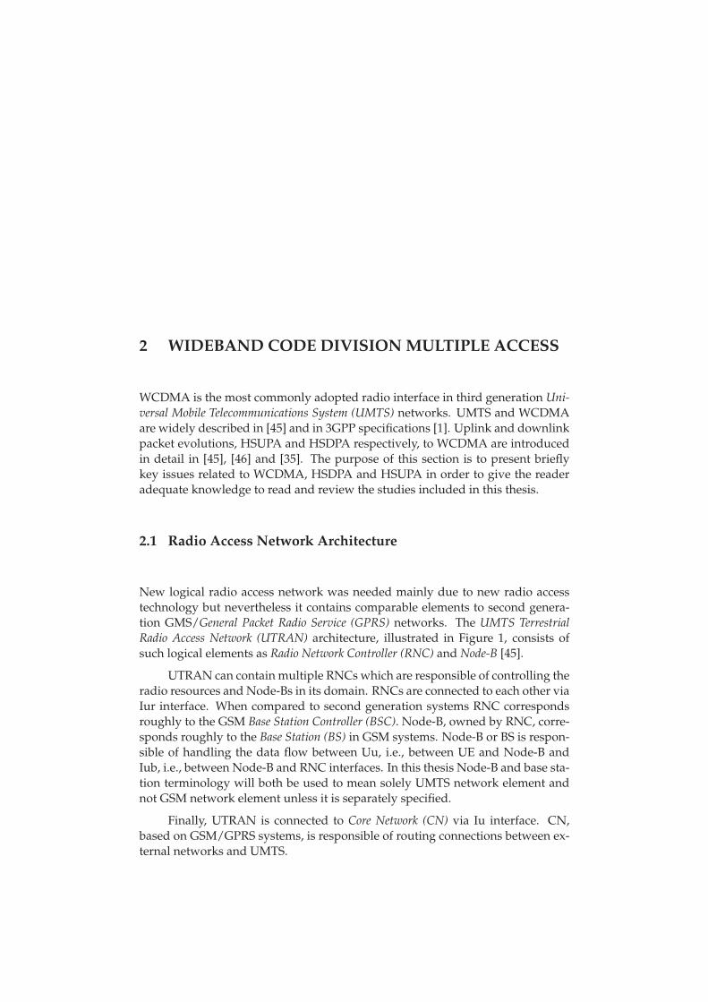
New logical radio access network was needed mainly due to new radio accesstechnology but nevertheless it contains comparable elements to second genera-tion GMS/General Packet Radio Service (GPRS) networks. The UMTS TerrestrialRadio Access Network (UTRAN) architecture, illustrated in Figure 1, consists ofsuch logical elements as Radio Network Controller (RNC) and Node-B [45].
UTRAN can contain multiple RNCs which are responsible of controlling theradio resources and Node-Bs in its domain. RNCs are connected to each other viaIur interface. When compared to second generation systems RNC correspondsroughly to the GSM Base Station Controller (BSC). Node-B, owned by RNC, corre-sponds roughly to the Base Station (BS) in GSM systems. Node-B or BS is respon-sible of handling the data flow between Uu, i.e., between UE and Node-B andIub, i.e., between Node-B and RNC interfaces. In this thesis Node-B and base sta-tion terminology will both be used to mean solely UMTS network element andnot GSM network element unless it is separately specified.
Finally, UTRAN is connected to Core Network (CN) via Iu interface. CN,based on GSM/GPRS systems, is responsible of routing connections between ex-ternal networks and UMTS.
31
FIGURE 1 UMTS Architecture
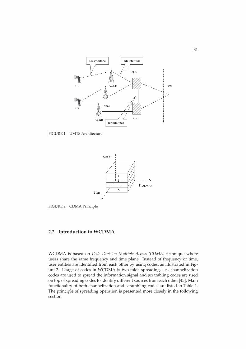
FIGURE 2 CDMA Principle
2.2 Introduction to WCDMA
WCDMA is based on Code Division Multiple Access (CDMA) technique whereusers share the same frequency and time plane. Instead of frequency or time,user entities are identified from each other by using codes, as illustrated in Fig-ure 2. Usage of codes in WCDMA is two-fold: spreading, i.e., channelizationcodes are used to spread the information signal and scrambling codes are usedon top of spreading codes to identify different sources from each other [45]. Mainfunctionality of both channelization and scrambling codes are listed in Table 1.The principle of spreading operation is presented more closely in the followingsection.
32
TABLE 1 Functionality of Codes in WCDMA, [45]
Channelization codes Scrambling codes
Usage in UL Separation of physical data Separation of terminalsand control channels fromsame terminal
Usage in DL Separation of downlink Separation of sectors (cells)connections to different userswithin one cell
Spreading Yes, increases transmission No, does not affectbandwidth transmission bandwidth
2.3 Spreading and Despreading
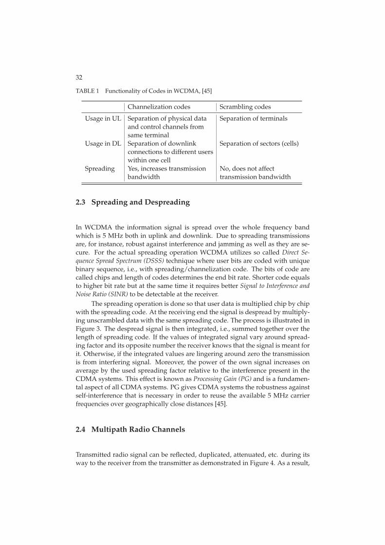
In WCDMA the information signal is spread over the whole frequency bandwhich is 5 MHz both in uplink and downlink. Due to spreading transmissionsare, for instance, robust against interference and jamming as well as they are se-cure. For the actual spreading operation WCDMA utilizes so called Direct Se-quence Spread Spectrum (DSSS) technique where user bits are coded with uniquebinary sequence, i.e., with spreading/channelization code. The bits of code arecalled chips and length of codes determines the end bit rate. Shorter code equalsto higher bit rate but at the same time it requires better Signal to Interference andNoise Ratio (SINR) to be detectable at the receiver.
The spreading operation is done so that user data is multiplied chip by chipwith the spreading code. At the receiving end the signal is despread by multiply-ing unscrambled data with the same spreading code. The process is illustrated inFigure 3. The despread signal is then integrated, i.e., summed together over thelength of spreading code. If the values of integrated signal vary around spread-ing factor and its opposite number the receiver knows that the signal is meant forit. Otherwise, if the integrated values are lingering around zero the transmissionis from interfering signal. Moreover, the power of the own signal increases onaverage by the used spreading factor relative to the interference present in theCDMA systems. This effect is known as Processing Gain (PG) and is a fundamen-tal aspect of all CDMA systems. PG gives CDMA systems the robustness againstself-interference that is necessary in order to reuse the available 5 MHz carrierfrequencies over geographically close distances [45].
2.4 Multipath Radio Channels
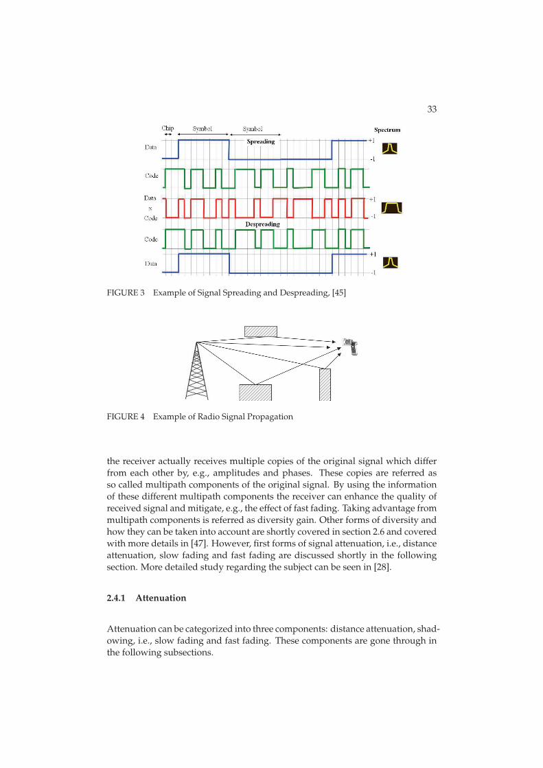
Transmitted radio signal can be reflected, duplicated, attenuated, etc. during itsway to the receiver from the transmitter as demonstrated in Figure 4. As a result,
33
FIGURE 3 Example of Signal Spreading and Despreading, [45]
FIGURE 4 Example of Radio Signal Propagation
the receiver actually receives multiple copies of the original signal which differfrom each other by, e.g., amplitudes and phases. These copies are referred asso called multipath components of the original signal. By using the informationof these different multipath components the receiver can enhance the quality ofreceived signal and mitigate, e.g., the effect of fast fading. Taking advantage frommultipath components is referred as diversity gain. Other forms of diversity andhow they can be taken into account are shortly covered in section 2.6 and coveredwith more details in [47]. However, first forms of signal attenuation, i.e., distanceattenuation, slow fading and fast fading are discussed shortly in the followingsection. More detailed study regarding the subject can be seen in [28].
2.4.1 Attenuation
Attenuation can be categorized into three components: distance attenuation, shad-owing, i.e., slow fading and fast fading. These components are gone through inthe following subsections.
34
2.4.1.1 Distance Attenuation
Distance attenuation, i.e., pathloss means the loss of a signal’s energy as it trav-els over the air from the transmitter to the receiver. The Okumura-Hata pathlossmodel is one of the most widely used for the calculations of coverage. Okumura-Hata model is based on the empirical measurements made by Y. Okumura inTokyo [70], which were then fitted into mathematical model by M. Hata [43]. Ini-tially Okumura-Hata model was applicable only for lower bandwidths but laterit was extended with COST 231 model [36], which made it applicable for band-widths covering also the area of 1500 ≤ f (MHz) ≤ 2000. This combined modelis called COST-Hata model and even though originally those applicable frequen-cies were restricted to below 2000 MHz, it is widely applied for UMTS frequenciesexceeding that. For macro cellular simulation purposes 3GPP has adopted modi-fied Okumura-Hata model which is described in detail in [21]. When consideringa carrier frequency of 2000 MHz and a base station antenna height of 15 meters,the modified model can be described as:
PL(d) = 128.1 + 37.6 × log10(d), (1)
where d is the distance expressed as kilometers. PL(d) shall in no circumstancesbe less than free space loss.
2.4.1.2 Slow Fading
Obstacles such as hills and buildings can come between the UE and Node-B andcreate so called shadowing to the received signal. Shadowing is caused by largermovements of a mobile within the propagation environment and usually it ischanging relatively slowly, hence it is often referred as slow fading. The amountof slow fading and more generally signal attenuation depends greatly on the en-vironment, for instance in the country side there can be much better propagationenvironment than in manhattan type of scenario where large number of build-ings are obstructing the signal. This type of fading is generally modeled througha process with a log normal distribution and a correlation distance when simula-tion tools are considered [21] [75].
2.4.1.3 Fast Fading
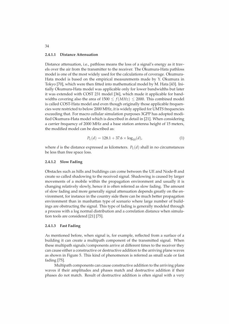
As mentioned before, when signal is, for example, reflected from a surface of abuilding it can create a multipath component of the transmitted signal. Whenthese multipath signals/components arrive at different times to the receiver theycan cause either a constructive or destructive addition to the arriving plane wavesas shown in Figure 5. This kind of phenomenon is referred as small scale or fastfading [75].
Multipath components can cause constructive addition to the arriving planewaves if their amplitudes and phases match and destructive addition if theirphases do not match. Result of destructive addition is often signal with a very
35
FIGURE 5 Example of Constructive (left hand side) and Destructive (right hand side)Addition
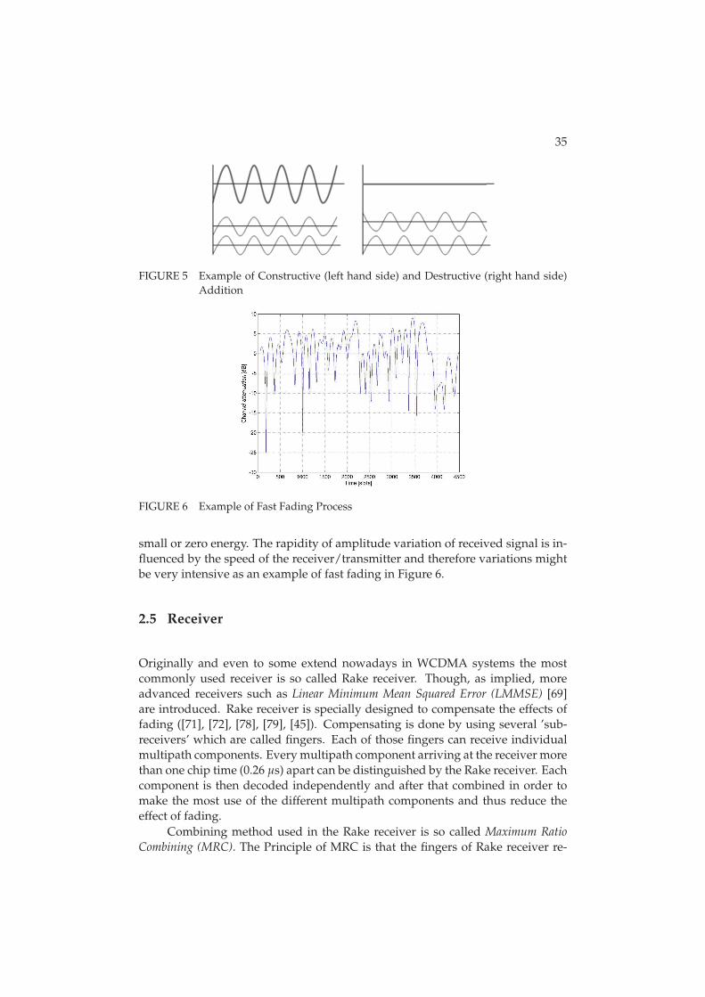
FIGURE 6 Example of Fast Fading Process
small or zero energy. The rapidity of amplitude variation of received signal is in-fluenced by the speed of the receiver/transmitter and therefore variations mightbe very intensive as an example of fast fading in Figure 6.
2.5 Receiver
Originally and even to some extend nowadays in WCDMA systems the mostcommonly used receiver is so called Rake receiver. Though, as implied, moreadvanced receivers such as Linear Minimum Mean Squared Error (LMMSE) [69]are introduced. Rake receiver is specially designed to compensate the effects offading ([71], [72], [78], [79], [45]). Compensating is done by using several ’sub-receivers’ which are called fingers. Each of those fingers can receive individualmultipath components. Every multipath component arriving at the receiver morethan one chip time (0.26 μs) apart can be distinguished by the Rake receiver. Eachcomponent is then decoded independently and after that combined in order tomake the most use of the different multipath components and thus reduce theeffect of fading.
Combining method used in the Rake receiver is so called Maximum RatioCombining (MRC). The Principle of MRC is that the fingers of Rake receiver re-
36
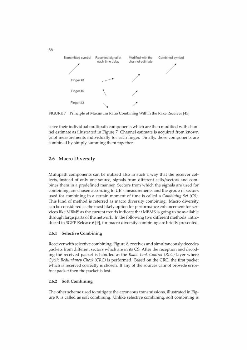
FIGURE 7 Principle of Maximum Ratio Combining Within the Rake Receiver [45]
ceive their individual multipath components which are then modified with chan-nel estimate as illustrated in Figure 7. Channel estimate is acquired from knownpilot measurements individually for each finger. Finally, those components arecombined by simply summing them together.
2.6 Macro Diversity
Multipath components can be utilized also in such a way that the receiver col-lects, instead of only one source, signals from different cells/sectors and com-bines them in a predefined manner. Sectors from which the signals are used forcombining, are chosen according to UE’s measurements and the group of sectorsused for combining in a certain moment of time is called a Combining Set (CS).This kind of method is referred as macro diversity combining. Macro diversitycan be considered as the most likely option for performance enhancement for ser-vices like MBMS as the current trends indicate that MBMS is going to be availablethrough large parts of the network. In the following two different methods, intro-duced in 3GPP Release 6 [9], for macro diversity combining are briefly presented.
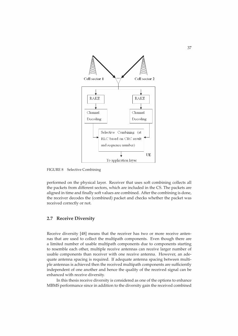
2.6.1 Selective Combining
Receiver with selective combining, Figure 8, receives and simultaneously decodespackets from different sectors which are in its CS. After the reception and decod-ing the received packet is handled at the Radio Link Control (RLC) layer whereCyclic Redundancy Check (CRC) is performed. Based on the CRC, the first packetwhich is received correctly is chosen. If any of the sources cannot provide error-free packet then the packet is lost.
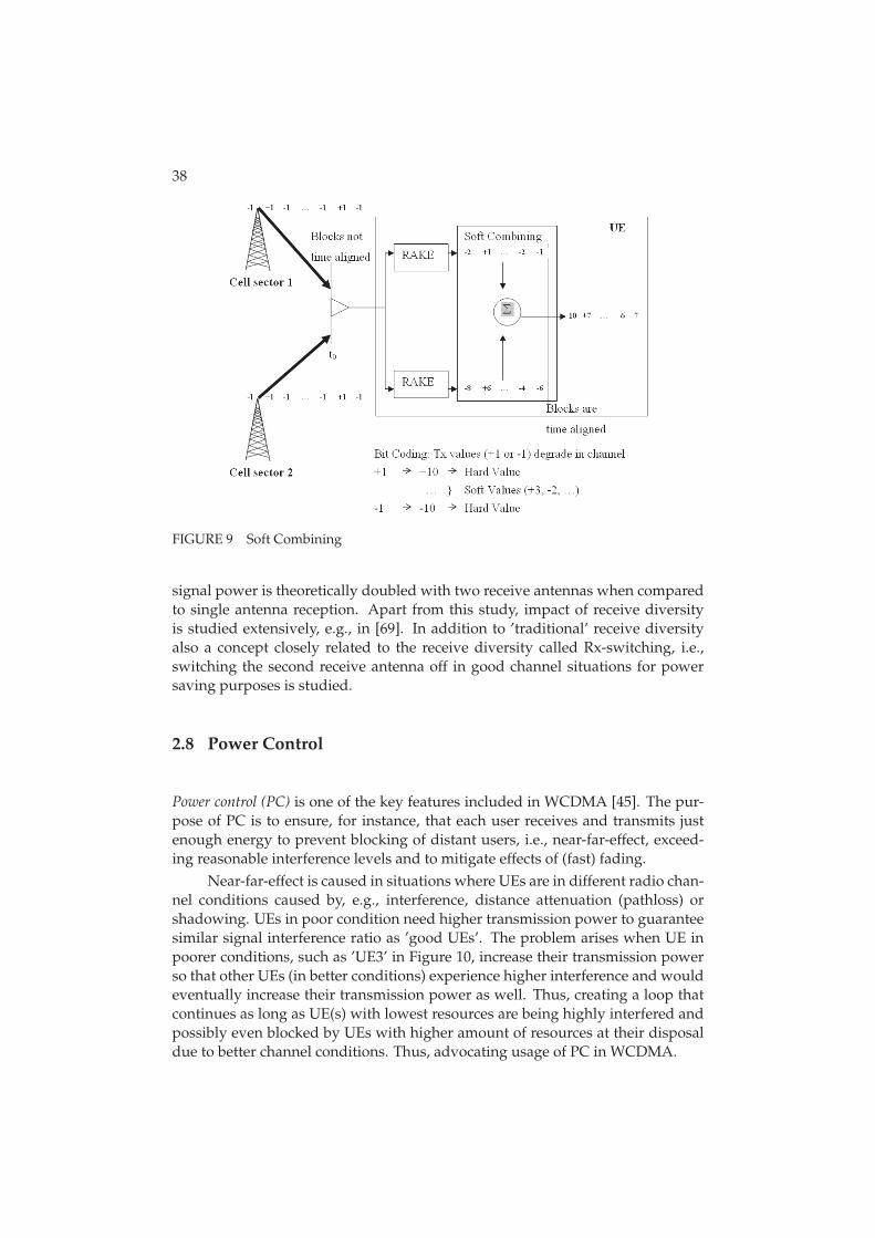
2.6.2 Soft Combining
The other scheme used to mitigate the erroneous transmissions, illustrated in Fig-ure 9, is called as soft combining. Unlike selective combining, soft combining is
37
FIGURE 8 Selective Combining
performed on the physical layer. Receiver that uses soft combining collects allthe packets from different sectors, which are included in the CS. The packets arealigned in time and finally soft values are combined. After the combining is done,the receiver decodes the (combined) packet and checks whether the packet wasreceived correctly or not.
2.7 Receive Diversity
Receive diversity [48] means that the receiver has two or more receive anten-nas that are used to collect the multipath components. Even though there area limited number of usable multipath components due to components startingto resemble each other, multiple receive antennas can receive larger number ofusable components than receiver with one receive antenna. However, an ade-quate antenna spacing is required. If adequate antenna spacing between multi-ple antennas is achieved then the received multipath components are sufficientlyindependent of one another and hence the quality of the received signal can beenhanced with receive diversity.
In this thesis receive diversity is considered as one of the options to enhanceMBMS performance since in addition to the diversity gain the received combined
38
FIGURE 9 Soft Combining
signal power is theoretically doubled with two receive antennas when comparedto single antenna reception. Apart from this study, impact of receive diversityis studied extensively, e.g., in [69]. In addition to ’traditional’ receive diversityalso a concept closely related to the receive diversity called Rx-switching, i.e.,switching the second receive antenna off in good channel situations for powersaving purposes is studied.
2.8 Power Control
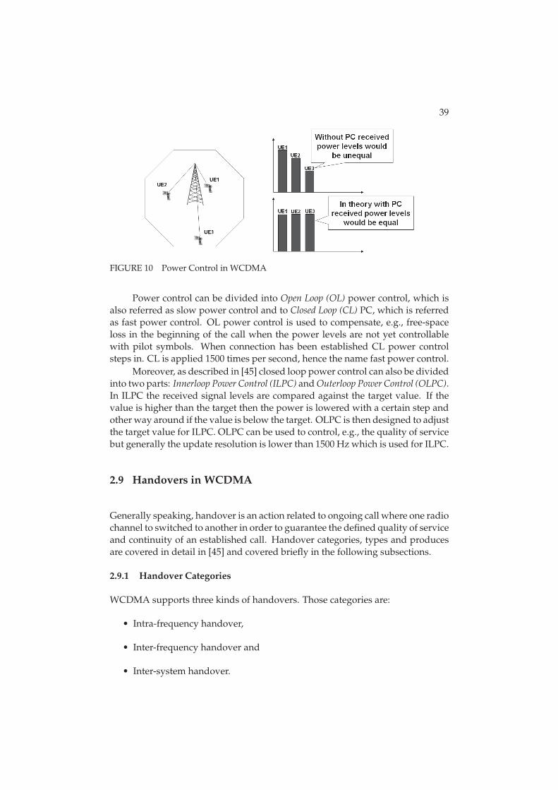
Power control (PC) is one of the key features included in WCDMA [45]. The pur-pose of PC is to ensure, for instance, that each user receives and transmits justenough energy to prevent blocking of distant users, i.e., near-far-effect, exceed-ing reasonable interference levels and to mitigate effects of (fast) fading.
Near-far-effect is caused in situations where UEs are in different radio chan-nel conditions caused by, e.g., interference, distance attenuation (pathloss) orshadowing. UEs in poor condition need higher transmission power to guaranteesimilar signal interference ratio as ’good UEs’. The problem arises when UE inpoorer conditions, such as ’UE3’ in Figure 10, increase their transmission powerso that other UEs (in better conditions) experience higher interference and wouldeventually increase their transmission power as well. Thus, creating a loop thatcontinues as long as UE(s) with lowest resources are being highly interfered andpossibly even blocked by UEs with higher amount of resources at their disposaldue to better channel conditions. Thus, advocating usage of PC in WCDMA.
39
FIGURE 10 Power Control in WCDMA
Power control can be divided into Open Loop (OL) power control, which isalso referred as slow power control and to Closed Loop (CL) PC, which is referredas fast power control. OL power control is used to compensate, e.g., free-spaceloss in the beginning of the call when the power levels are not yet controllablewith pilot symbols. When connection has been established CL power controlsteps in. CL is applied 1500 times per second, hence the name fast power control.
Moreover, as described in [45] closed loop power control can also be dividedinto two parts: Innerloop Power Control (ILPC) and Outerloop Power Control (OLPC).In ILPC the received signal levels are compared against the target value. If thevalue is higher than the target then the power is lowered with a certain step andother way around if the value is below the target. OLPC is then designed to adjustthe target value for ILPC. OLPC can be used to control, e.g., the quality of servicebut generally the update resolution is lower than 1500 Hz which is used for ILPC.
2.9 Handovers in WCDMA
Generally speaking, handover is an action related to ongoing call where one radiochannel to switched to another in order to guarantee the defined quality of serviceand continuity of an established call. Handover categories, types and producesare covered in detail in [45] and covered briefly in the following subsections.
2.9.1 Handover Categories
WCDMA supports three kinds of handovers. Those categories are:
• Intra-frequency handover,
• Inter-frequency handover and
• Inter-system handover.
40
Intra-frequency handover means a handover procedure within the same frequencyand system. Inter-frequency HO is a handover between different frequencies butwithin the same system. And finally, inter-system HO is handover to anothersystem, e.g., from WCDMA to GSM.
2.9.2 Handover Types
Different handover categories support only certain type of handovers. Handovertypes can be divided into soft, softer and hard handover. Soft handover is a han-dover between different base stations, where UE is connected simultaneously tomultiple base stations and thus the transition between them should be seamless.Softer handover is a handover within the coverage area of one base station butbetween different sectors. Actual functionality of softer handover is similar tosoft handover and thus the transition should also be seamless. Finally, hard han-dover is such that the source is released first and then new one is added, thusshort interruption time in the service is expected.
From the different types mentioned before intra-frequency handover is in away the most versatile as it supports soft, softer and hard handover. In contrast,inter-frequency and inter-system handovers support only hard handovers.
2.9.3 Soft and Softer Handover Procedure
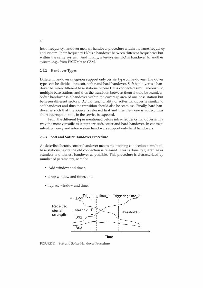
As described before, soft(er) handover means maintaining connection to multiplebase stations before the old connection is released. This is done to guarantee asseamless and lossless handover as possible. This procedure is characterized bynumber of parameters, namely:
• Add window and timer,
• drop window and timer, and
• replace window and timer.
FIGURE 11 Soft and Softer Handover Procedure
41
Add window indicates a value of how much poorer a new signal can be com-pared to the best one in the current active set in order to be added into the set.Candidate needs meet the criteria at least for the duration of add timer. How-ever, adding link to combining set can be done only if maximum number of linksis not full yet (defined with parameter). Add procedure is illustrated in exampleof soft(er) HO procedure in Figure 11 as ’Threshold_1’ and ’Triggering time_1’.
The opposite for adding is dropping the link from the active set. Link is tobe dropped if the ’drop window’ parameter, illustrated as ’Threshold_2’ in thefigure, is met. Similarly to adding also signal which is to be dropped needs tofulfill the drop condition after the corresponding drop timer is expired.
Finally, ’replace window’ represents a value for how much better a newsignal has to be compared to the poorest one in the current active set in order toreplace its place. Replace event takes place only if active set is full as otherwise’add’ event would be applied.
2.10 Channels in WCDMA
In WCDMA there exists two types of transport channels: Dedicated Channels (DCHs)and common channels. The main difference between them is that the resourcesare shared between users when common channels are used whereas a DCH re-source is reserved for a single user only that is continuous and independent fromthe DCHs of other UEs. The main transport channels used for packet data trans-missions in WCDMA are called as DCH and Forward Access Channel (FACH) [45].
In WCDMA systems there exists only one dedicated channel which is knownas DCH. DCH is mapped into physical data and control channels, Dedicated Phys-ical Control Channel (DPDCH) and Dedicated Physical Control Channel (DPCCH),respectively. DPDCH is used to carry user data and DPCCH all higher layer con-trol information, such as handover and power control commands. Fast data ratechange on a frame-by-frame basis is supported in the uplink. However, in thedownlink data rate variation is taken care of either with a rate-matching opera-tion or with Discontinuous Transmission (DTX) instead of varying spreading factorframe-by-frame basis. If downlink rate matching is used then data bits are eitherrepeated to increase the rate or punctured to decrease the rate. With DTX thetransmission is off during a certain part of the slot.
FACH is a shared downlink transport channel that can be used to carrypacket data in addition to mandatory control information. FACH is used, forinstance, to indicate that random access message has been received by BTS. AsFACH carries vital control information, FACH has to have low enough bit rate soit can be received by all the UEs in the cell area. However, there can be more thanone FACH in a cell enabling the possibility to have higher bit rates for the otherFACHs. The FACH does not support fast power control or soft handover.
In addition to FACH there are five common channels in WCDMA: the Broad-cast Channel (BCH), Paging Channel (PCH), Random Access Channel (RACH), Uplink
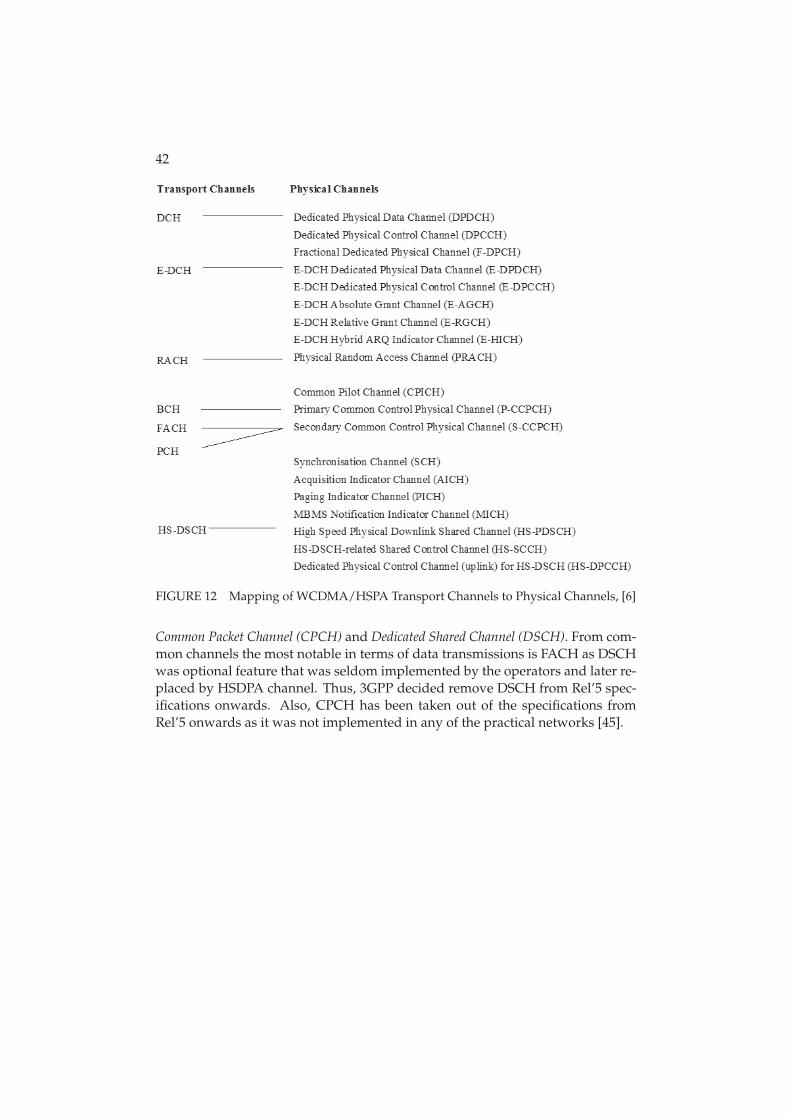
42
FIGURE 12 Mapping of WCDMA/HSPA Transport Channels to Physical Channels, [6]
Common Packet Channel (CPCH) and Dedicated Shared Channel (DSCH). From com-mon channels the most notable in terms of data transmissions is FACH as DSCHwas optional feature that was seldom implemented by the operators and later re-placed by HSDPA channel. Thus, 3GPP decided remove DSCH from Rel’5 spec-ifications onwards. Also, CPCH has been taken out of the specifications fromRel’5 onwards as it was not implemented in any of the practical networks [45].
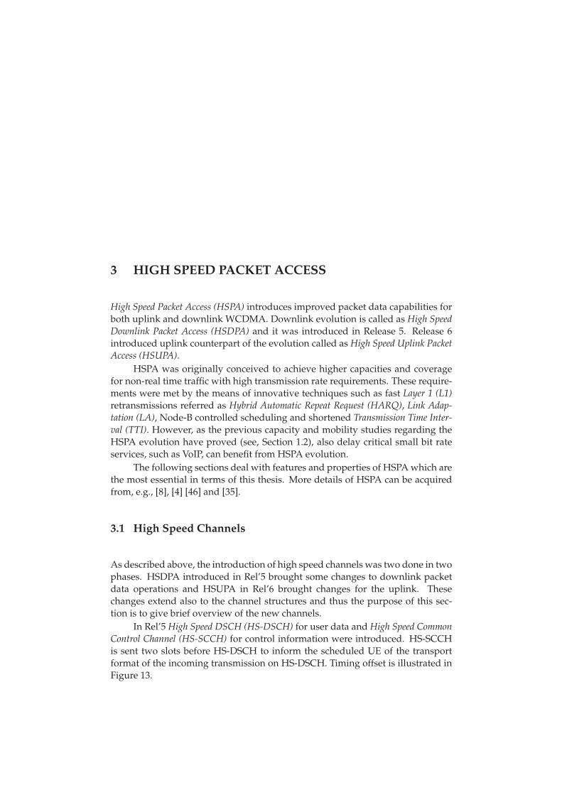
3 HIGH SPEED PACKET ACCESS
High Speed Packet Access (HSPA) introduces improved packet data capabilities forboth uplink and downlink WCDMA. Downlink evolution is called as High SpeedDownlink Packet Access (HSDPA) and it was introduced in Release 5. Release 6introduced uplink counterpart of the evolution called as High Speed Uplink PacketAccess (HSUPA).
HSPA was originally conceived to achieve higher capacities and coveragefor non-real time traffic with high transmission rate requirements. These require-ments were met by the means of innovative techniques such as fast Layer 1 (L1)retransmissions referred as Hybrid Automatic Repeat Request (HARQ), Link Adap-tation (LA), Node-B controlled scheduling and shortened Transmission Time Inter-val (TTI). However, as the previous capacity and mobility studies regarding theHSPA evolution have proved (see, Section 1.2), also delay critical small bit rateservices, such as VoIP, can benefit from HSPA evolution.
The following sections deal with features and properties of HSPA which arethe most essential in terms of this thesis. More details of HSPA can be acquiredfrom, e.g., [8], [4] [46] and [35].
3.1 High Speed Channels
As described above, the introduction of high speed channels was two done in twophases. HSDPA introduced in Rel’5 brought some changes to downlink packetdata operations and HSUPA in Rel’6 brought changes for the uplink. Thesechanges extend also to the channel structures and thus the purpose of this sec-tion is to give brief overview of the new channels.
In Rel’5 High Speed DSCH (HS-DSCH) for user data and High Speed CommonControl Channel (HS-SCCH) for control information were introduced. HS-SCCHis sent two slots before HS-DSCH to inform the scheduled UE of the transportformat of the incoming transmission on HS-DSCH. Timing offset is illustrated inFigure 13.
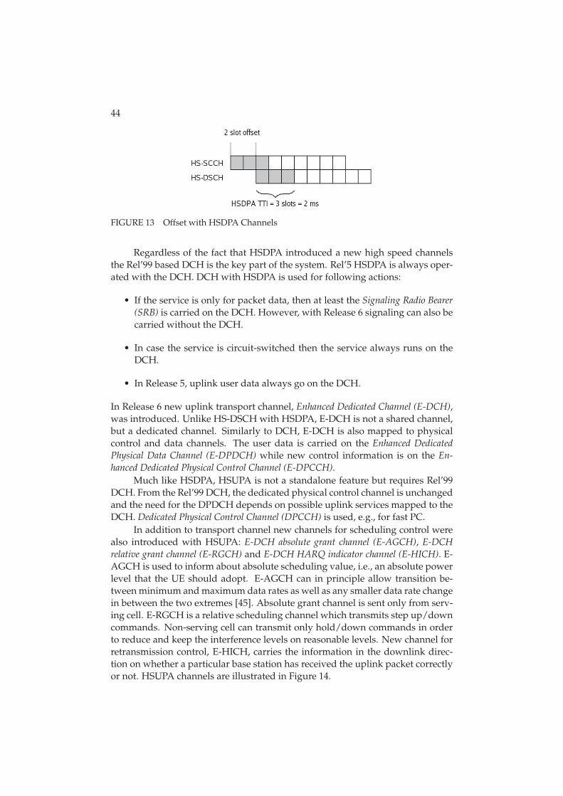
44
FIGURE 13 Offset with HSDPA Channels
Regardless of the fact that HSDPA introduced a new high speed channelsthe Rel’99 based DCH is the key part of the system. Rel’5 HSDPA is always oper-ated with the DCH. DCH with HSDPA is used for following actions:
• If the service is only for packet data, then at least the Signaling Radio Bearer(SRB) is carried on the DCH. However, with Release 6 signaling can also becarried without the DCH.
• In case the service is circuit-switched then the service always runs on theDCH.
• In Release 5, uplink user data always go on the DCH.
In Release 6 new uplink transport channel, Enhanced Dedicated Channel (E-DCH),was introduced. Unlike HS-DSCH with HSDPA, E-DCH is not a shared channel,but a dedicated channel. Similarly to DCH, E-DCH is also mapped to physicalcontrol and data channels. The user data is carried on the Enhanced DedicatedPhysical Data Channel (E-DPDCH) while new control information is on the En-hanced Dedicated Physical Control Channel (E-DPCCH).
Much like HSDPA, HSUPA is not a standalone feature but requires Rel’99DCH. From the Rel’99 DCH, the dedicated physical control channel is unchangedand the need for the DPDCH depends on possible uplink services mapped to theDCH. Dedicated Physical Control Channel (DPCCH) is used, e.g., for fast PC.
In addition to transport channel new channels for scheduling control werealso introduced with HSUPA: E-DCH absolute grant channel (E-AGCH), E-DCHrelative grant channel (E-RGCH) and E-DCH HARQ indicator channel (E-HICH). E-AGCH is used to inform about absolute scheduling value, i.e., an absolute powerlevel that the UE should adopt. E-AGCH can in principle allow transition be-tween minimum and maximum data rates as well as any smaller data rate changein between the two extremes [45]. Absolute grant channel is sent only from serv-ing cell. E-RGCH is a relative scheduling channel which transmits step up/downcommands. Non-serving cell can transmit only hold/down commands in orderto reduce and keep the interference levels on reasonable levels. New channel forretransmission control, E-HICH, carries the information in the downlink direc-tion on whether a particular base station has received the uplink packet correctlyor not. HSUPA channels are illustrated in Figure 14.
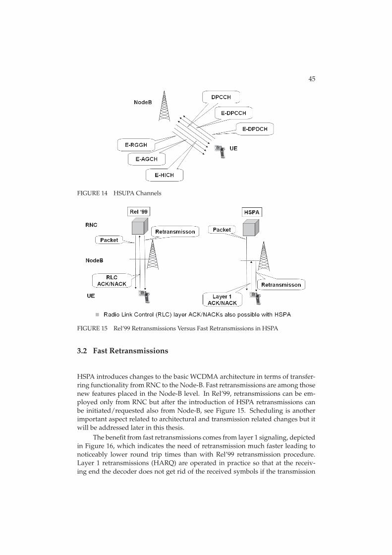
45
FIGURE 14 HSUPA Channels
FIGURE 15 Rel’99 Retransmissions Versus Fast Retransmissions in HSPA
3.2 Fast Retransmissions
HSPA introduces changes to the basic WCDMA architecture in terms of transfer-ring functionality from RNC to the Node-B. Fast retransmissions are among thosenew features placed in the Node-B level. In Rel’99, retransmissions can be em-ployed only from RNC but after the introduction of HSPA retransmissions canbe initiated/requested also from Node-B, see Figure 15. Scheduling is anotherimportant aspect related to architectural and transmission related changes but itwill be addressed later in this thesis.
The benefit from fast retransmissions comes from layer 1 signaling, depictedin Figure 16, which indicates the need of retransmission much faster leading tonoticeably lower round trip times than with Rel’99 retransmission procedure.Layer 1 retransmissions (HARQ) are operated in practice so that at the receiv-ing end the decoder does not get rid of the received symbols if the transmission
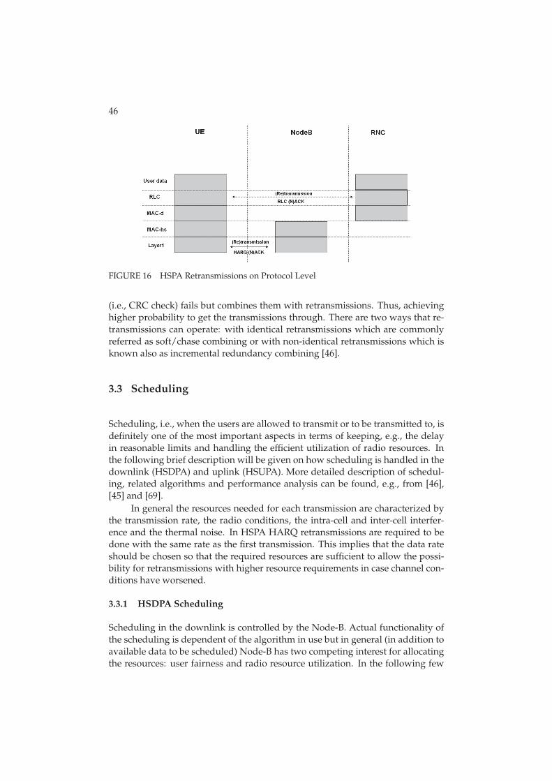
46
FIGURE 16 HSPA Retransmissions on Protocol Level
(i.e., CRC check) fails but combines them with retransmissions. Thus, achievinghigher probability to get the transmissions through. There are two ways that re-transmissions can operate: with identical retransmissions which are commonlyreferred as soft/chase combining or with non-identical retransmissions which isknown also as incremental redundancy combining [46].
3.3 Scheduling
Scheduling, i.e., when the users are allowed to transmit or to be transmitted to, isdefinitely one of the most important aspects in terms of keeping, e.g., the delayin reasonable limits and handling the efficient utilization of radio resources. Inthe following brief description will be given on how scheduling is handled in thedownlink (HSDPA) and uplink (HSUPA). More detailed description of schedul-ing, related algorithms and performance analysis can be found, e.g., from [46],[45] and [69].
In general the resources needed for each transmission are characterized bythe transmission rate, the radio conditions, the intra-cell and inter-cell interfer-ence and the thermal noise. In HSPA HARQ retransmissions are required to bedone with the same rate as the first transmission. This implies that the data rateshould be chosen so that the required resources are sufficient to allow the possi-bility for retransmissions with higher resource requirements in case channel con-ditions have worsened.
3.3.1 HSDPA Scheduling
Scheduling in the downlink is controlled by the Node-B. Actual functionality ofthe scheduling is dependent of the algorithm in use but in general (in addition toavailable data to be scheduled) Node-B has two competing interest for allocatingthe resources: user fairness and radio resource utilization. In the following few
47
different scheduling algorithms are presented that handle fairness and resourceutilization in different manners.
3.3.1.1 Round Robin
Round Robin (RR) [46] is one of the most simplest scheduling algorithms and itis often used as a benchmarking reference for more advanced scheduling algo-rithms. With RR users are served in sequential order, i.e., all users are handledwithout priority. Positive sides with RR are that it is very easy to implementand each user gets served equally. On another hand, channel conditions are nottaken into account and thus valuable radio resources might be wasted and thusnetwork throughput might suffer.
3.3.1.2 Max C/I
When compared to RR Max C/I [46] is the other extreme of the scheduling alter-natives if channel conditions and the scheduling fairness between users are takenas indicators. Whereas RR schedules users in sequential order Max C/I sched-ules users purely according their channel conditions. The user that has the bestchannel conditions in given time gets scheduled. This maximizes the throughputfrom the network perspective but the user fairness can suffer significantly.
3.3.1.3 Proportional Fair
Proportional Fair (PF) [46] is a compromise-based scheduling algorithm basedupon maintaining a balance between two competing interests: maximizing net-work throughput by serving users in good channel conditions but at the sametime allowing all users at least a minimal level of service. In practice this is doneby assigning each users a scheduling priority that is inversely proportional toits anticipated resource consumption. High resource consumption leads to lowpriority and vice versa. However, priority is shifted with the factor which takesinto account the occasions the user has been scheduled previously. In general thepriority metric for users is calculated in a following manner [45], [46]:
p = d/r. (2)
In Eq. 2 the instantaneous data rate, d, is obtained by consulting the link adapta-tion algorithm and average throughput of the user, r, is defined as follows:
r ={
(1 − a)× rold + a × d, if the user is served(1 − a)× rold, otherwise.
(3)
Here a is so called forgetting factor. Hence, a−1 equals to the equivalent averagingperiod in a number of TTIs for the exponential smoothing filter.
48
3.3.1.4 VoIP Optimized PF
Normal proportional fair scheduler has some disadvantages when delay criticaltraffic is considered as it does not take delay of the queued packets into account assuch. Improved scheduling and resource allocation algorithm for VoIP has beenstudied closely in [82] and [66]. Those papers present enhancement to pure PFalgorithm by introducing so called Scheduling Candidate Set (SCS) from which theactual scheduling algorithm, for instance PF, selects users from. SCS is updatedin each TTI so that it includes users who have certain number of VoIP packetsbuffered in the Node-B, whose Head-of-Line (HoL) packet delay is large enough orwho have pending retransmissions in their HARQ manager.
3.3.2 HSUPA Scheduling
Scheduling for uplink is necessary to keep the interference levels reasonable 1
and thus improving the probability to get transmissions through. Similarly toHSDPA, also HSUPA scheduling has been moved from RNC to Node-B makingthe scheduling decisions happening with minimum latency. Regarding HSUPAtwo different scheduling schemes are defined: scheduled transmissions and Non-Scheduled Transmissions (NST) [46].
3.3.2.1 Scheduled Transmissions
Scheduled transmissions are, as the name implies, controlled by Node-B. Node-Band UEs will signal of the data rate requirements and how much resources UEshas available (referred also as power headroom) and then the Node-B assignsmaximum transmit rate for each user so that the interference level experiencedat the BS will not exceed certain reasonable level. However, the downside ofscheduled transmissions with this approach is that when, for instance, VoIP isconsidered satisfactory minimum bit rate might not be achieved and in additioneach request requires time and resource consuming signaling.
3.3.2.2 Non-scheduled Transmissions
NSTs are controlled by RNC which defines a minimum data rate at which theUE can transmit without any previous request. This reduces signaling overheadand consequently processing delays. To meet the tight delay requirements set forVoIP application, RNC controlled NTS of E-DCH is the most suitable choice forVoIP traffic as it enables the UE to transmit the VoIP packets as soon as they arriveto the physical layer.
1 measured generally through Rise over Thermal (RoT), i.e., noise rise which indicates the ratiobetween the total power received from all of the UEs at the base station and the thermalnoise [80]
49
3.4 Multiplexing
As referred earlier, HSPA was designed originally to provide higher data ratesfor the end-users. When introducing relatively low bit rate services, such as VoIP,capacity could be wasted by serving only one user at a time. To allow schedulingof multiple users per TTI mulplexing schemes for both HSDPA and HSUPA havebeen developed [46]. In the following those will be presented briefly.
3.4.1 HSDPA Multiplexing
In HSDPA multiplexing users to a single TTI transmission is handled throughcode multiplexing. For instance, assuming 15 available codes and three users tobe scheduled, each could be served with five codes during the same TTI. How-ever, each simultaneously scheduled HSDPA user requires HS-SCCH channel.Thus, total amount of required power for HS-SCCH increases when users arecode multiplexed and moreover it also limits the number of code-multiplexedusers.
3.4.2 HSUPA Multiplexing
Multiplexing of users in HSUPA systems can be accomplished through three dif-ferent ways:
• Code Division Multiplexing (CDM),
• Time Division Multiplexing (TDM), or
• CDM/TDM.
With pure CDM all users are first provided with minimum bit rate which is fol-lowed by reserving resources for retransmissions. After that higher allocationscan be given according to the scheduling priority metric (and request) and Riseover Thermal (RoT) level that the scheduler is aiming at as Figure 17 illustrates.
TDM allows only one user to be scheduled in each TTI resulting in increasedqueuing times but also reduced interference levels. Retransmissions are priori-tized over new transmissions due to synchronous HSUPA HARQ operation. Fig-ure 18 shows TDM procedure and from which components RoT is consisting ofover the predicted interference.
Combination of the two above, CDM/TDM, does not guarantee minimumbit rate for all users but does not limit the maximum number of scheduled usersto only one either. The amount of multiplexed users is up to the RoT level that thescheduler is aiming at. Each user, up until RoT target is reached, is allocated withbit rate according to scheduling priority metric and request as it is illustrated inFigure 19.
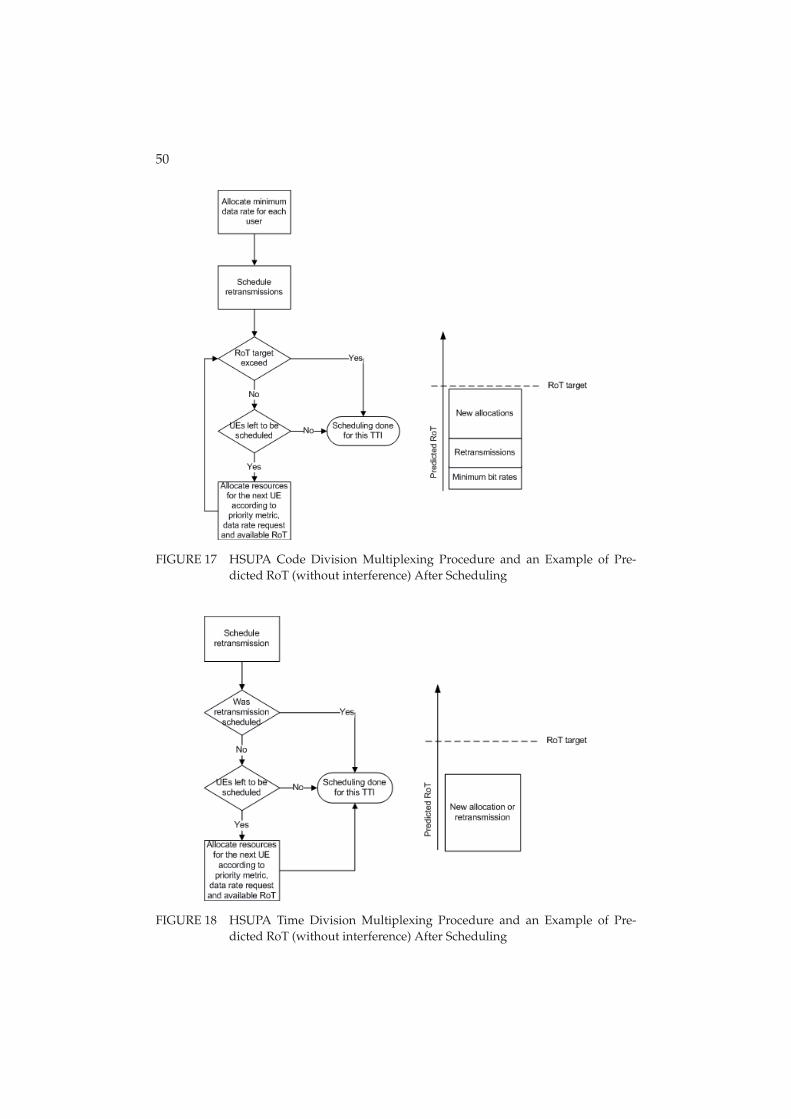
50
FIGURE 17 HSUPA Code Division Multiplexing Procedure and an Example of Pre-dicted RoT (without interference) After Scheduling
FIGURE 18 HSUPA Time Division Multiplexing Procedure and an Example of Pre-dicted RoT (without interference) After Scheduling
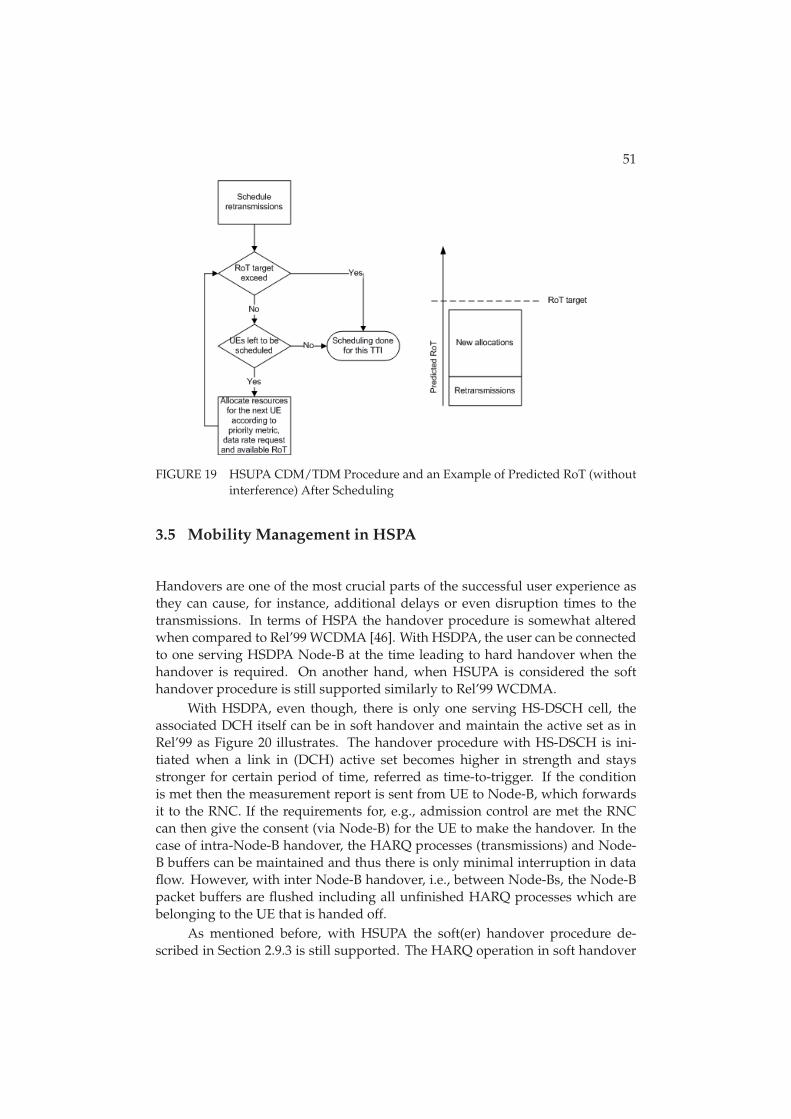
51
FIGURE 19 HSUPA CDM/TDM Procedure and an Example of Predicted RoT (withoutinterference) After Scheduling
3.5 Mobility Management in HSPA
Handovers are one of the most crucial parts of the successful user experience asthey can cause, for instance, additional delays or even disruption times to thetransmissions. In terms of HSPA the handover procedure is somewhat alteredwhen compared to Rel’99 WCDMA [46]. With HSDPA, the user can be connectedto one serving HSDPA Node-B at the time leading to hard handover when thehandover is required. On another hand, when HSUPA is considered the softhandover procedure is still supported similarly to Rel’99 WCDMA.
With HSDPA, even though, there is only one serving HS-DSCH cell, theassociated DCH itself can be in soft handover and maintain the active set as inRel’99 as Figure 20 illustrates. The handover procedure with HS-DSCH is ini-tiated when a link in (DCH) active set becomes higher in strength and staysstronger for certain period of time, referred as time-to-trigger. If the conditionis met then the measurement report is sent from UE to Node-B, which forwardsit to the RNC. If the requirements for, e.g., admission control are met the RNCcan then give the consent (via Node-B) for the UE to make the handover. In thecase of intra-Node-B handover, the HARQ processes (transmissions) and Node-B buffers can be maintained and thus there is only minimal interruption in dataflow. However, with inter Node-B handover, i.e., between Node-Bs, the Node-Bpacket buffers are flushed including all unfinished HARQ processes which arebelonging to the UE that is handed off.
As mentioned before, with HSUPA the soft(er) handover procedure de-scribed in Section 2.9.3 is still supported. The HARQ operation in soft handover
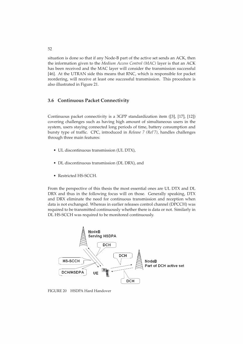
52
situation is done so that if any Node-B part of the active set sends an ACK, thenthe information given to the Medium Access Control (MAC) layer is that an ACKhas been received and the MAC layer will consider the transmission successful[46]. At the UTRAN side this means that RNC, which is responsible for packetreordering, will receive at least one successful transmission. This procedure isalso illustrated in Figure 21.
3.6 Continuous Packet Connectivity
Continuous packet connectivity is a 3GPP standardization item ([3], [17], [12])covering challenges such as having high amount of simultaneous users in thesystem, users staying connected long periods of time, battery consumption andbursty type of traffic. CPC, introduced in Release 7 (Rel’7), handles challengesthrough three main features:
• UL discontinuous transmission (UL DTX),
• DL discontinuous transmission (DL DRX), and
• Restricted HS-SCCH.
From the perspective of this thesis the most essential ones are UL DTX and DLDRX and thus in the following focus will on those. Generally speaking, DTXand DRX eliminate the need for continuous transmission and reception whendata is not exchanged. Whereas in earlier releases control channel (DPCCH) wasrequired to be transmitted continuously whether there is data or not. Similarly inDL HS-SCCH was required to be monitored continuously.
FIGURE 20 HSDPA Hard Handover
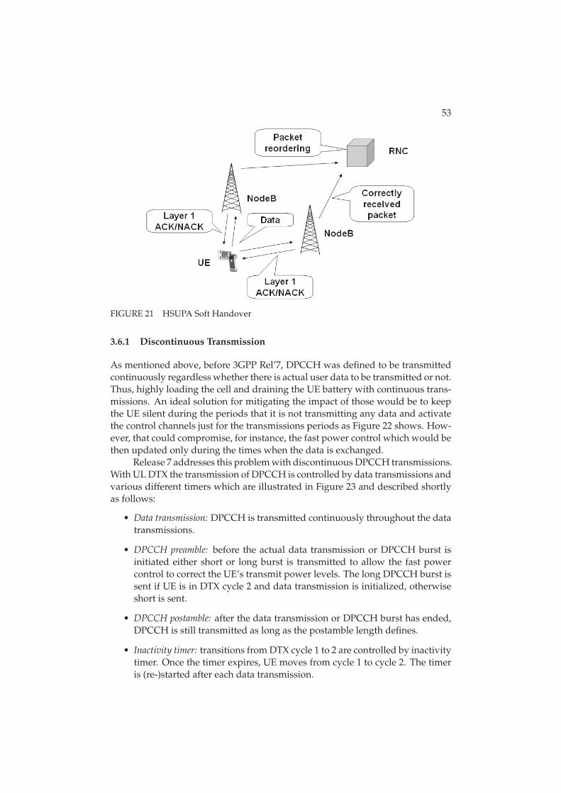
53
FIGURE 21 HSUPA Soft Handover
3.6.1 Discontinuous Transmission
As mentioned above, before 3GPP Rel’7, DPCCH was defined to be transmittedcontinuously regardless whether there is actual user data to be transmitted or not.Thus, highly loading the cell and draining the UE battery with continuous trans-missions. An ideal solution for mitigating the impact of those would be to keepthe UE silent during the periods that it is not transmitting any data and activatethe control channels just for the transmissions periods as Figure 22 shows. How-ever, that could compromise, for instance, the fast power control which would bethen updated only during the times when the data is exchanged.
Release 7 addresses this problem with discontinuous DPCCH transmissions.With UL DTX the transmission of DPCCH is controlled by data transmissions andvarious different timers which are illustrated in Figure 23 and described shortlyas follows:
• Data transmission: DPCCH is transmitted continuously throughout the datatransmissions.
• DPCCH preamble: before the actual data transmission or DPCCH burst isinitiated either short or long burst is transmitted to allow the fast powercontrol to correct the UE’s transmit power levels. The long DPCCH burst issent if UE is in DTX cycle 2 and data transmission is initialized, otherwiseshort is sent.
• DPCCH postamble: after the data transmission or DPCCH burst has ended,DPCCH is still transmitted as long as the postamble length defines.
• Inactivity timer: transitions from DTX cycle 1 to 2 are controlled by inactivitytimer. Once the timer expires, UE moves from cycle 1 to cycle 2. The timeris (re-)started after each data transmission.
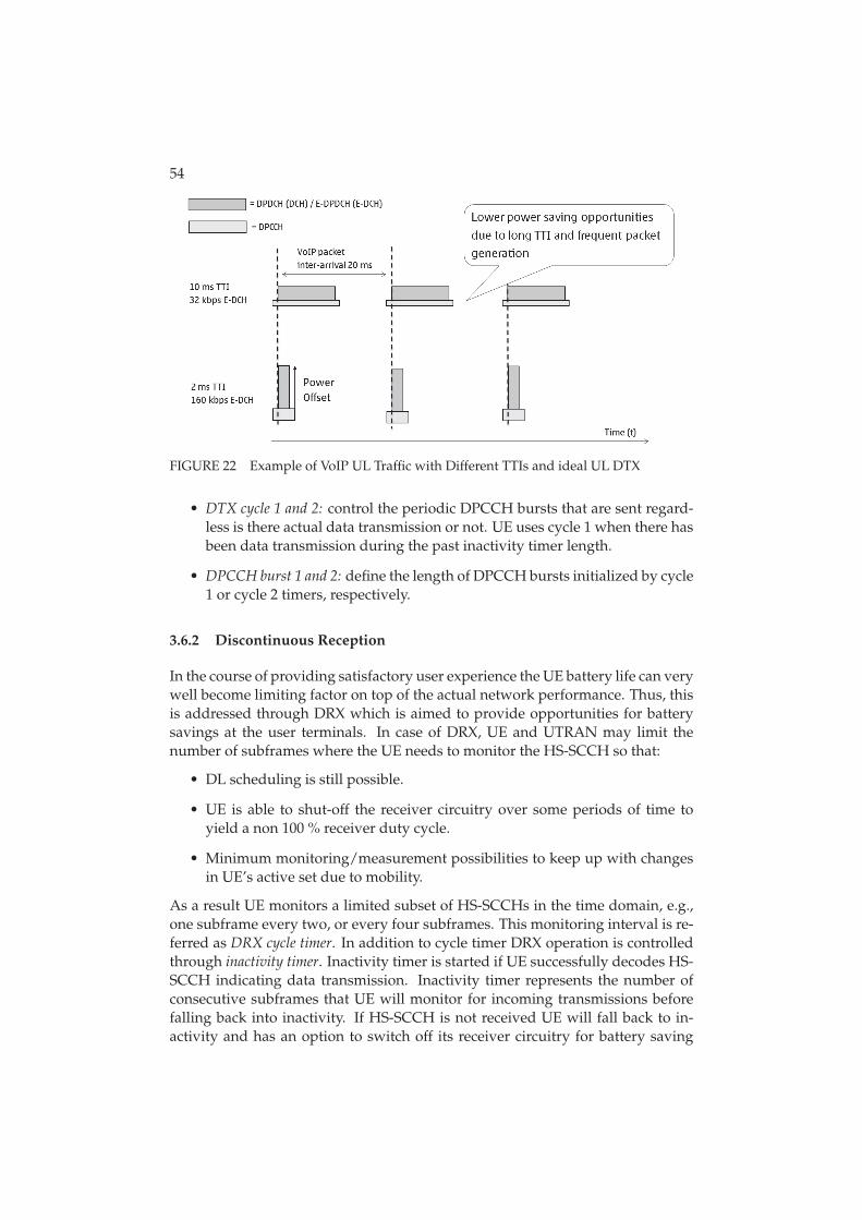
54
FIGURE 22 Example of VoIP UL Traffic with Different TTIs and ideal UL DTX
• DTX cycle 1 and 2: control the periodic DPCCH bursts that are sent regard-less is there actual data transmission or not. UE uses cycle 1 when there hasbeen data transmission during the past inactivity timer length.
• DPCCH burst 1 and 2: define the length of DPCCH bursts initialized by cycle1 or cycle 2 timers, respectively.
3.6.2 Discontinuous Reception
In the course of providing satisfactory user experience the UE battery life can verywell become limiting factor on top of the actual network performance. Thus, thisis addressed through DRX which is aimed to provide opportunities for batterysavings at the user terminals. In case of DRX, UE and UTRAN may limit thenumber of subframes where the UE needs to monitor the HS-SCCH so that:
• DL scheduling is still possible.
• UE is able to shut-off the receiver circuitry over some periods of time toyield a non 100 % receiver duty cycle.
• Minimum monitoring/measurement possibilities to keep up with changesin UE’s active set due to mobility.
As a result UE monitors a limited subset of HS-SCCHs in the time domain, e.g.,one subframe every two, or every four subframes. This monitoring interval is re-ferred as DRX cycle timer. In addition to cycle timer DRX operation is controlledthrough inactivity timer. Inactivity timer is started if UE successfully decodes HS-SCCH indicating data transmission. Inactivity timer represents the number ofconsecutive subframes that UE will monitor for incoming transmissions beforefalling back into inactivity. If HS-SCCH is not received UE will fall back to in-activity and has an option to switch off its receiver circuitry for battery saving
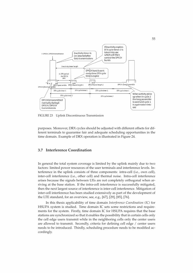
55
FIGURE 23 Uplink Discontinuous Transmission
purposes. Moreover, DRX cycles should be adjusted with different offsets for dif-ferent terminals to guarantee fair and adequate scheduling opportunities in thetime domain. Example of DRX operation is illustrated in Figure 24.
3.7 Interference Coordination
In general the total system coverage is limited by the uplink mainly due to twofactors: limited power resources of the user terminals and interference levels. In-terference in the uplink consists of three components: intra-cell (i.e., own cell),inter-cell interference (i.e., other cell) and thermal noise. Intra-cell interferencearises because the signals between UEs are not completely orthogonal when ar-riving at the base station. If the intra-cell interference is successfully mitigated,then the next largest source of interference is inter-cell interference. Mitigation ofinter-cell interference has been studied extensively as part of the development ofthe LTE standard, for an overview, see, e.g., [67], [29], [85], [76].
In this thesis applicability of time domain Interference Coordination (IC) forHSUPA system is studied. Time domain IC sets some restrictions and require-ments for the system. Firstly, time domain IC for HSUPA requires that the basestations are synchronized so that it enables the possibility that in certain cells onlythe cell edge users transmit while in the neighboring cells only the center usersare allowed to transmit. Secondly, criteria for defining cell edge / center usersneeds to be introduced. Thirdly, scheduling procedure needs to be modified ac-cordingly.
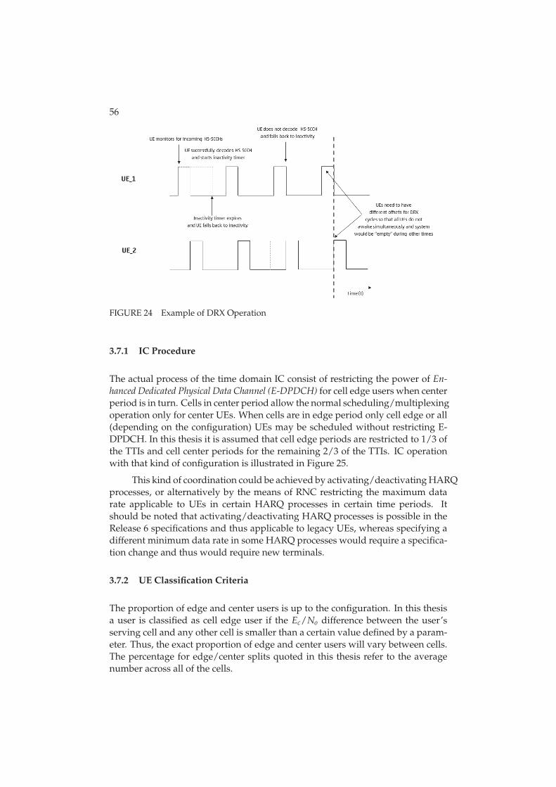
56
FIGURE 24 Example of DRX Operation
3.7.1 IC Procedure
The actual process of the time domain IC consist of restricting the power of En-hanced Dedicated Physical Data Channel (E-DPDCH) for cell edge users when centerperiod is in turn. Cells in center period allow the normal scheduling/multiplexingoperation only for center UEs. When cells are in edge period only cell edge or all(depending on the configuration) UEs may be scheduled without restricting E-DPDCH. In this thesis it is assumed that cell edge periods are restricted to 1/3 ofthe TTIs and cell center periods for the remaining 2/3 of the TTIs. IC operationwith that kind of configuration is illustrated in Figure 25.
This kind of coordination could be achieved by activating/deactivating HARQprocesses, or alternatively by the means of RNC restricting the maximum datarate applicable to UEs in certain HARQ processes in certain time periods. Itshould be noted that activating/deactivating HARQ processes is possible in theRelease 6 specifications and thus applicable to legacy UEs, whereas specifying adifferent minimum data rate in some HARQ processes would require a specifica-tion change and thus would require new terminals.
3.7.2 UE Classification Criteria
The proportion of edge and center users is up to the configuration. In this thesisa user is classified as cell edge user if the Ec/No difference between the user’sserving cell and any other cell is smaller than a certain value defined by a param-eter. Thus, the exact proportion of edge and center users will vary between cells.The percentage for edge/center splits quoted in this thesis refer to the averagenumber across all of the cells.
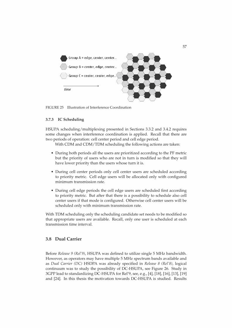
57
FIGURE 25 Illustration of Interference Coordination
3.7.3 IC Scheduling
HSUPA scheduling/multiplexing presented in Sections 3.3.2 and 3.4.2 requiressome changes when interference coordination is applied. Recall that there aretwo periods of operation: cell center period and cell edge period.
With CDM and CDM/TDM scheduling the following actions are taken:
• During both periods all the users are prioritized according to the PF metricbut the priority of users who are not in turn is modified so that they willhave lower priority than the users whose turn it is.
• During cell center periods only cell center users are scheduled accordingto priority metric. Cell edge users will be allocated only with configuredminimum transmission rate.
• During cell edge periods the cell edge users are scheduled first accordingto priority metric. But after that there is a possibility to schedule also cellcenter users if that mode is configured. Otherwise cell center users will bescheduled only with minimum transmission rate.
With TDM scheduling only the scheduling candidate set needs to be modified sothat appropriate users are available. Recall, only one user is scheduled at eachtransmission time interval.
3.8 Dual Carrier
Before Release 9 (Rel’9), HSUPA was defined to utilize single 5 MHz bandwidth.However, as operators may have multiple 5 MHz spectrum bands available andas Dual Carrier (DC) HSDPA was already specified in Release 8 (Rel’8), logicalcontinuum was to study the possibility of DC-HSUPA, see Figure 26. Study in3GPP lead to standardizing DC-HSUPA for Rel’9, see, e.g., [4], [18], [16], [13], [19]and [24]. In this thesis the motivation towards DC-HSUPA is studied. Results
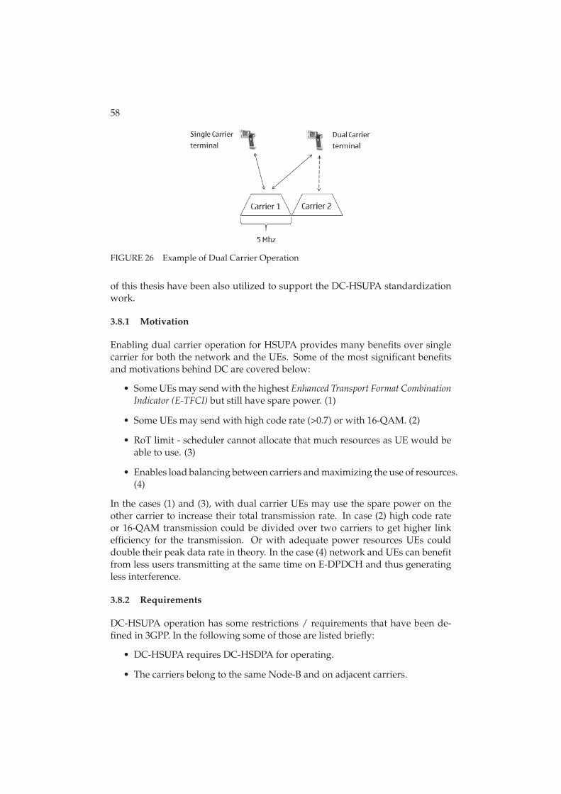
58
FIGURE 26 Example of Dual Carrier Operation
of this thesis have been also utilized to support the DC-HSUPA standardizationwork.
3.8.1 Motivation
Enabling dual carrier operation for HSUPA provides many benefits over singlecarrier for both the network and the UEs. Some of the most significant benefitsand motivations behind DC are covered below:
• Some UEs may send with the highest Enhanced Transport Format CombinationIndicator (E-TFCI) but still have spare power. (1)
• Some UEs may send with high code rate (>0.7) or with 16-QAM. (2)
• RoT limit - scheduler cannot allocate that much resources as UE would beable to use. (3)
• Enables load balancing between carriers and maximizing the use of resources.(4)
In the cases (1) and (3), with dual carrier UEs may use the spare power on theother carrier to increase their total transmission rate. In case (2) high code rateor 16-QAM transmission could be divided over two carriers to get higher linkefficiency for the transmission. Or with adequate power resources UEs coulddouble their peak data rate in theory. In the case (4) network and UEs can benefitfrom less users transmitting at the same time on E-DPDCH and thus generatingless interference.
3.8.2 Requirements
DC-HSUPA operation has some restrictions / requirements that have been de-fined in 3GPP. In the following some of those are listed briefly:
• DC-HSUPA requires DC-HSDPA for operating.
• The carriers belong to the same Node-B and on adjacent carriers.
59
• UE has a single Power Amplifier (PA) and the total transmit power is sharedbetween carriers.
• Control channels are transmitted on both channels.
In addition those requirements, naturally, additional spectrum and terminal sup-port is also required to implement DC in practice.
3.8.3 Scheduling
Scheduling with dual carrier follows the same principles as Sections 3.3.2 and3.4.2 present. However, due to availability of two carriers in order to maximizethe resource utilization slight modifications to scheduling could be needed. Inthe following three potential methods to handle DC-HSUPA scheduling are pre-sented.
3.8.3.1 DC Scheduling 1
Scheduling of UEs is always done according to their priority metric on Carrier 1(C1). In other words C1 is scheduled first and then Carrier 2 (C2) in the sameorder. This can leave C2 slightly inefficient as rate requests are done for C1 andwhen C2 is scheduled the best UEs and request are not necessarily scheduledfirst. However, this kind of scheduling should provide frequency diversity gainfor the terminals transmitting on both carriers.
3.8.3.2 DC Scheduling 2
Second scheduling option is similar to option 1 when C1 is question. However,when C2 is in question, the UEs that were not scheduled on C1 are scheduledfirst on C2. This kind of scheduling resembles scheduling of two separate singlecarriers with the exception that UEs can switch more easily between carriers.
3.8.3.3 DC Scheduling 3
Third scheduling option presented here is such that rate requests (done by theUE) and scheduling (by Node-B) takes into account which carrier is better (i.e.,has lower DPCCH level). UEs are sorted to a list according to their better carrierand UEs are scheduled in that order with each UE having its better carrier sched-uled first. This kind of scheduling should improve the utilization of both carriersand provide frequency diversity gain as well.
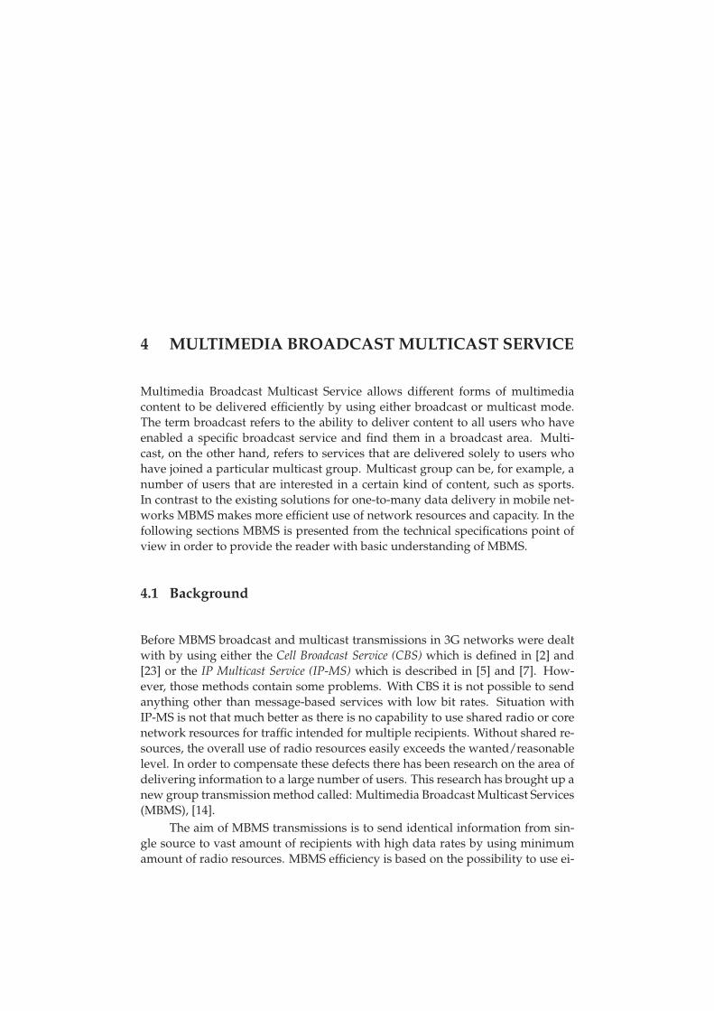
4 MULTIMEDIA BROADCAST MULTICAST SERVICE
Multimedia Broadcast Multicast Service allows different forms of multimediacontent to be delivered efficiently by using either broadcast or multicast mode.The term broadcast refers to the ability to deliver content to all users who haveenabled a specific broadcast service and find them in a broadcast area. Multi-cast, on the other hand, refers to services that are delivered solely to users whohave joined a particular multicast group. Multicast group can be, for example, anumber of users that are interested in a certain kind of content, such as sports.In contrast to the existing solutions for one-to-many data delivery in mobile net-works MBMS makes more efficient use of network resources and capacity. In thefollowing sections MBMS is presented from the technical specifications point ofview in order to provide the reader with basic understanding of MBMS.
4.1 Background
Before MBMS broadcast and multicast transmissions in 3G networks were dealtwith by using either the Cell Broadcast Service (CBS) which is defined in [2] and[23] or the IP Multicast Service (IP-MS) which is described in [5] and [7]. How-ever, those methods contain some problems. With CBS it is not possible to sendanything other than message-based services with low bit rates. Situation withIP-MS is not that much better as there is no capability to use shared radio or corenetwork resources for traffic intended for multiple recipients. Without shared re-sources, the overall use of radio resources easily exceeds the wanted/reasonablelevel. In order to compensate these defects there has been research on the area ofdelivering information to a large number of users. This research has brought up anew group transmission method called: Multimedia Broadcast Multicast Services(MBMS), [14].
The aim of MBMS transmissions is to send identical information from sin-gle source to vast amount of recipients with high data rates by using minimumamount of radio resources. MBMS efficiency is based on the possibility to use ei-
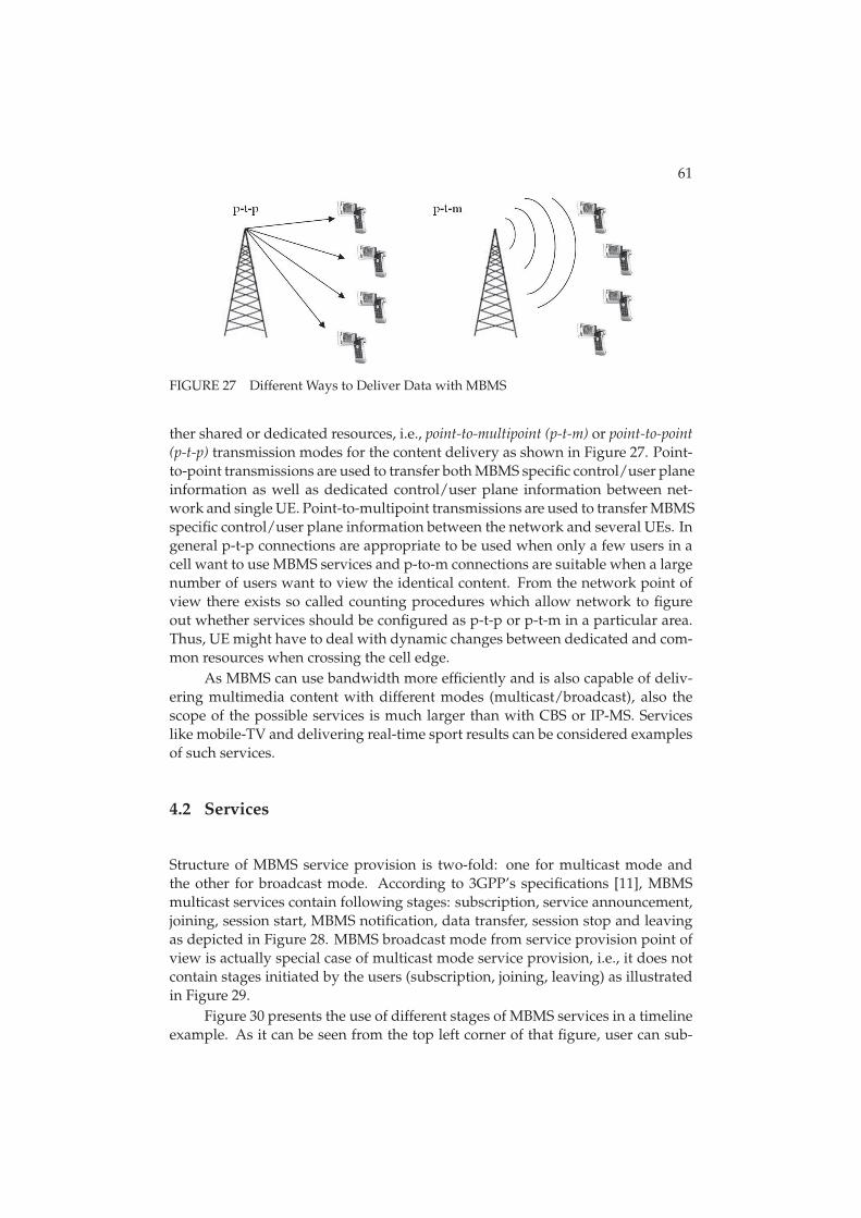
61
FIGURE 27 Different Ways to Deliver Data with MBMS
ther shared or dedicated resources, i.e., point-to-multipoint (p-t-m) or point-to-point(p-t-p) transmission modes for the content delivery as shown in Figure 27. Point-to-point transmissions are used to transfer both MBMS specific control/user planeinformation as well as dedicated control/user plane information between net-work and single UE. Point-to-multipoint transmissions are used to transfer MBMSspecific control/user plane information between the network and several UEs. Ingeneral p-t-p connections are appropriate to be used when only a few users in acell want to use MBMS services and p-to-m connections are suitable when a largenumber of users want to view the identical content. From the network point ofview there exists so called counting procedures which allow network to figureout whether services should be configured as p-t-p or p-t-m in a particular area.Thus, UE might have to deal with dynamic changes between dedicated and com-mon resources when crossing the cell edge.
As MBMS can use bandwidth more efficiently and is also capable of deliv-ering multimedia content with different modes (multicast/broadcast), also thescope of the possible services is much larger than with CBS or IP-MS. Serviceslike mobile-TV and delivering real-time sport results can be considered examplesof such services.
4.2 Services
Structure of MBMS service provision is two-fold: one for multicast mode andthe other for broadcast mode. According to 3GPP’s specifications [11], MBMSmulticast services contain following stages: subscription, service announcement,joining, session start, MBMS notification, data transfer, session stop and leavingas depicted in Figure 28. MBMS broadcast mode from service provision point ofview is actually special case of multicast mode service provision, i.e., it does notcontain stages initiated by the users (subscription, joining, leaving) as illustratedin Figure 29.
Figure 30 presents the use of different stages of MBMS services in a timelineexample. As it can be seen from the top left corner of that figure, user can sub-
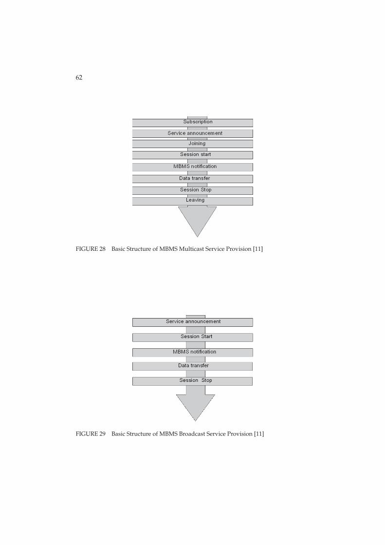
62
FIGURE 28 Basic Structure of MBMS Multicast Service Provision [11]
FIGURE 29 Basic Structure of MBMS Broadcast Service Provision [11]
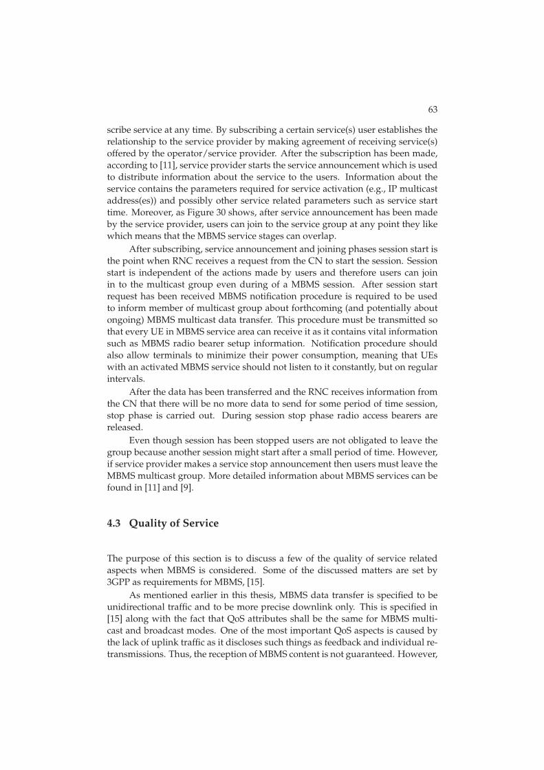
63
scribe service at any time. By subscribing a certain service(s) user establishes therelationship to the service provider by making agreement of receiving service(s)offered by the operator/service provider. After the subscription has been made,according to [11], service provider starts the service announcement which is usedto distribute information about the service to the users. Information about theservice contains the parameters required for service activation (e.g., IP multicastaddress(es)) and possibly other service related parameters such as service starttime. Moreover, as Figure 30 shows, after service announcement has been madeby the service provider, users can join to the service group at any point they likewhich means that the MBMS service stages can overlap.
After subscribing, service announcement and joining phases session start isthe point when RNC receives a request from the CN to start the session. Sessionstart is independent of the actions made by users and therefore users can joinin to the multicast group even during of a MBMS session. After session startrequest has been received MBMS notification procedure is required to be usedto inform member of multicast group about forthcoming (and potentially aboutongoing) MBMS multicast data transfer. This procedure must be transmitted sothat every UE in MBMS service area can receive it as it contains vital informationsuch as MBMS radio bearer setup information. Notification procedure shouldalso allow terminals to minimize their power consumption, meaning that UEswith an activated MBMS service should not listen to it constantly, but on regularintervals.
After the data has been transferred and the RNC receives information fromthe CN that there will be no more data to send for some period of time session,stop phase is carried out. During session stop phase radio access bearers arereleased.
Even though session has been stopped users are not obligated to leave thegroup because another session might start after a small period of time. However,if service provider makes a service stop announcement then users must leave theMBMS multicast group. More detailed information about MBMS services can befound in [11] and [9].
4.3 Quality of Service
The purpose of this section is to discuss a few of the quality of service relatedaspects when MBMS is considered. Some of the discussed matters are set by3GPP as requirements for MBMS, [15].
As mentioned earlier in this thesis, MBMS data transfer is specified to beunidirectional traffic and to be more precise downlink only. This is specified in[15] along with the fact that QoS attributes shall be the same for MBMS multi-cast and broadcast modes. One of the most important QoS aspects is caused bythe lack of uplink traffic as it discloses such things as feedback and individual re-transmissions. Thus, the reception of MBMS content is not guaranteed. However,
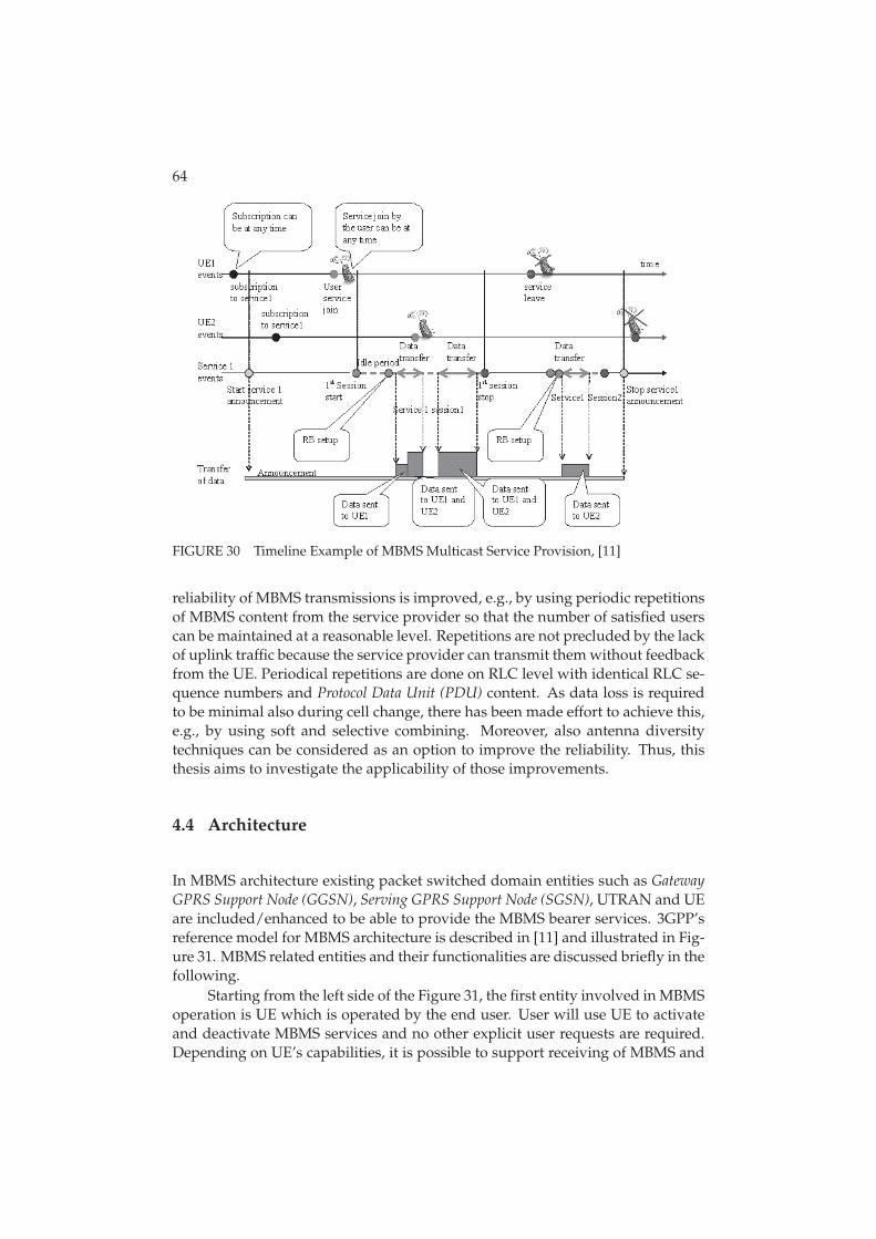
64
FIGURE 30 Timeline Example of MBMS Multicast Service Provision, [11]
reliability of MBMS transmissions is improved, e.g., by using periodic repetitionsof MBMS content from the service provider so that the number of satisfied userscan be maintained at a reasonable level. Repetitions are not precluded by the lackof uplink traffic because the service provider can transmit them without feedbackfrom the UE. Periodical repetitions are done on RLC level with identical RLC se-quence numbers and Protocol Data Unit (PDU) content. As data loss is requiredto be minimal also during cell change, there has been made effort to achieve this,e.g., by using soft and selective combining. Moreover, also antenna diversitytechniques can be considered as an option to improve the reliability. Thus, thisthesis aims to investigate the applicability of those improvements.
4.4 Architecture
In MBMS architecture existing packet switched domain entities such as GatewayGPRS Support Node (GGSN), Serving GPRS Support Node (SGSN), UTRAN and UEare included/enhanced to be able to provide the MBMS bearer services. 3GPP’sreference model for MBMS architecture is described in [11] and illustrated in Fig-ure 31. MBMS related entities and their functionalities are discussed briefly in thefollowing.
Starting from the left side of the Figure 31, the first entity involved in MBMSoperation is UE which is operated by the end user. User will use UE to activateand deactivate MBMS services and no other explicit user requests are required.Depending on UE’s capabilities, it is possible to support receiving of MBMS and
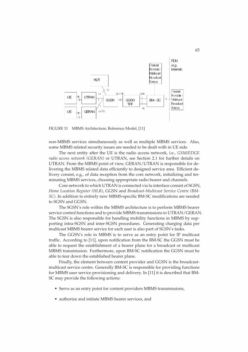
65
FIGURE 31 MBMS Architecture; Reference Model, [11]
non-MBMS services simultaneously as well as multiple MBMS services. Also,some MBMS related security issues are needed to be dealt with in UE side.
The next entity after the UE is the radio access network, i.e., GSM/EDGEradio access network (GERAN) or UTRAN, see Section 2.1 for further details onUTRAN. From the MBMS point of view, GERAN/UTRAN is responsible for de-livering the MBMS related data efficiently to designed service area. Efficient de-livery consist, e.g., of data reception from the core network, initializing and ter-minating MBMS services, choosing appropriate radio bearer and channels.
Core network to which UTRAN is connected via lu interface consist of SGSN,Home Location Register (HLR), GGSN and Broadcast-Multicast Service Centre (BM-SC). In addition to entirely new MBMS-specific BM-SC modifications are neededto SGSN and GGSN.
The SGSN’s role within the MBMS architecture is to perform MBMS bearerservice control functions and to provide MBMS transmissions to UTRAN/GERAN.The SGSN is also responsible for handling mobility functions in MBMS by sup-porting intra-SGSN and inter-SGSN procedures. Generating charging data permulticast MBMS bearer service for each user is also part of SGSN’s tasks.
The GGSN’s role in MBMS is to serve as an entry point for IP multicasttraffic. According to [11], upon notification from the BM-SC the GGSN must beable to request the establishment of a bearer plane for a broadcast or multicastMBMS transmission. Furthermore, upon BM-SC notification the GGSN must beable to tear down the established bearer plane.
Finally, the element between content provider and GGSN is the broadcast-multicast service centre. Generally BM-SC is responsible for providing functionsfor MBMS user service provisioning and delivery. In [11] it is described that BM-SC may provide the following actions:
• Serve as an entry point for content providers MBMS transmissions,
• authorize and initiate MBMS bearer services, and
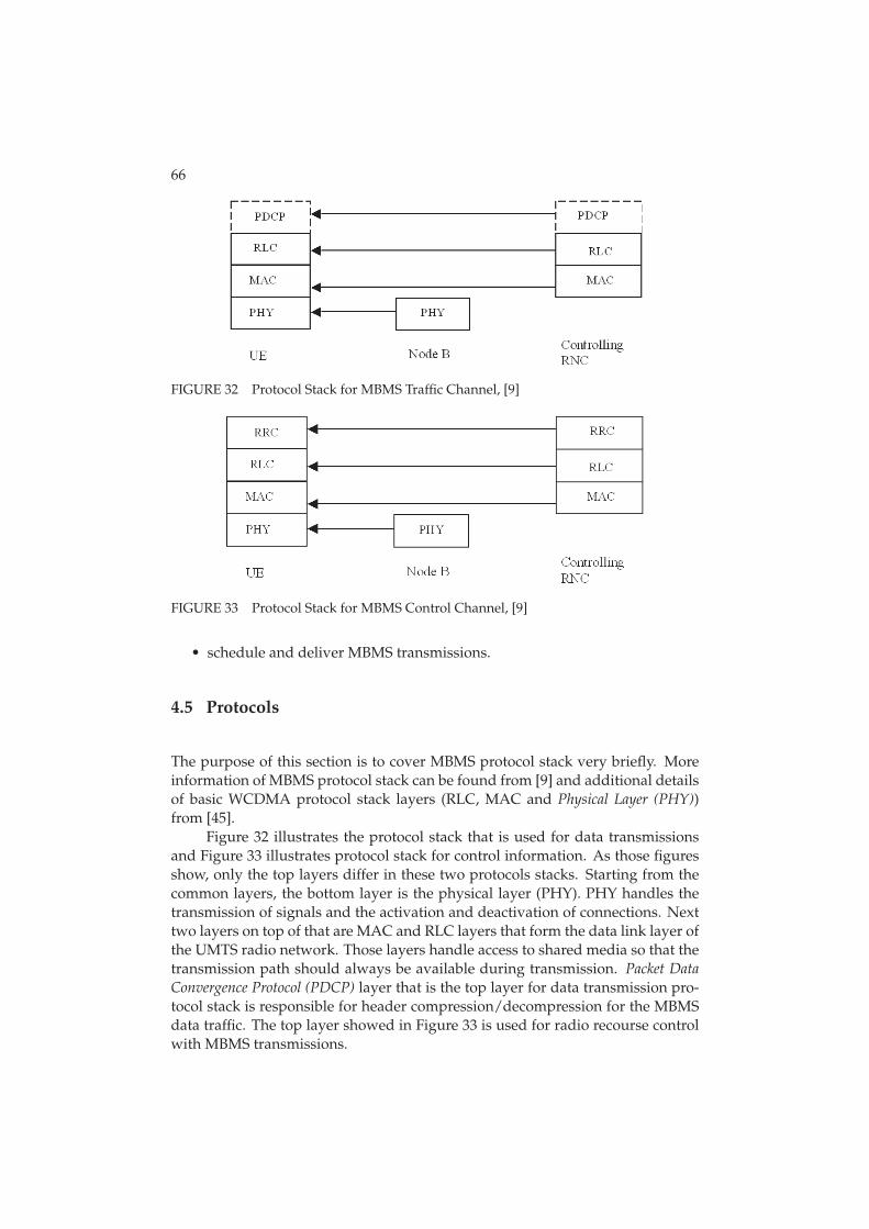
66
FIGURE 32 Protocol Stack for MBMS Traffic Channel, [9]
FIGURE 33 Protocol Stack for MBMS Control Channel, [9]
• schedule and deliver MBMS transmissions.
4.5 Protocols
The purpose of this section is to cover MBMS protocol stack very briefly. Moreinformation of MBMS protocol stack can be found from [9] and additional detailsof basic WCDMA protocol stack layers (RLC, MAC and Physical Layer (PHY))from [45].
Figure 32 illustrates the protocol stack that is used for data transmissionsand Figure 33 illustrates protocol stack for control information. As those figuresshow, only the top layers differ in these two protocols stacks. Starting from thecommon layers, the bottom layer is the physical layer (PHY). PHY handles thetransmission of signals and the activation and deactivation of connections. Nexttwo layers on top of that are MAC and RLC layers that form the data link layer ofthe UMTS radio network. Those layers handle access to shared media so that thetransmission path should always be available during transmission. Packet DataConvergence Protocol (PDCP) layer that is the top layer for data transmission pro-tocol stack is responsible for header compression/decompression for the MBMSdata traffic. The top layer showed in Figure 33 is used for radio recourse controlwith MBMS transmissions.
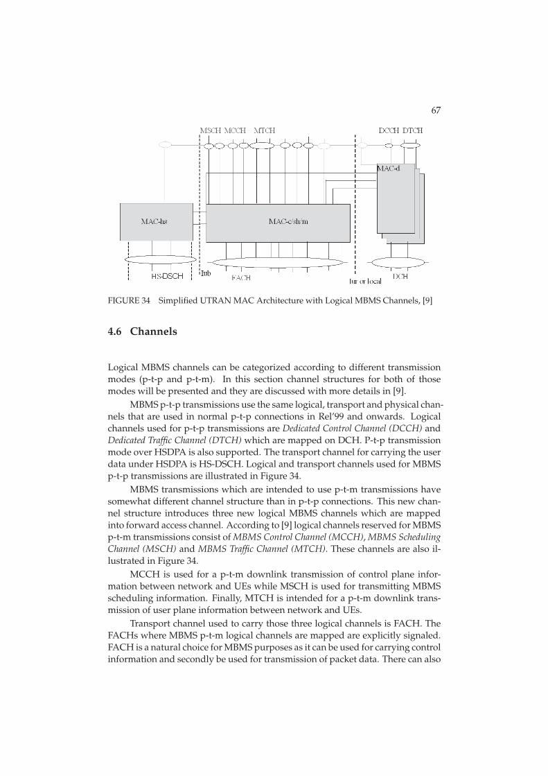
67
FIGURE 34 Simplified UTRAN MAC Architecture with Logical MBMS Channels, [9]
4.6 Channels
Logical MBMS channels can be categorized according to different transmissionmodes (p-t-p and p-t-m). In this section channel structures for both of thosemodes will be presented and they are discussed with more details in [9].
MBMS p-t-p transmissions use the same logical, transport and physical chan-nels that are used in normal p-t-p connections in Rel’99 and onwards. Logicalchannels used for p-t-p transmissions are Dedicated Control Channel (DCCH) andDedicated Traffic Channel (DTCH) which are mapped on DCH. P-t-p transmissionmode over HSDPA is also supported. The transport channel for carrying the userdata under HSDPA is HS-DSCH. Logical and transport channels used for MBMSp-t-p transmissions are illustrated in Figure 34.
MBMS transmissions which are intended to use p-t-m transmissions havesomewhat different channel structure than in p-t-p connections. This new chan-nel structure introduces three new logical MBMS channels which are mappedinto forward access channel. According to [9] logical channels reserved for MBMSp-t-m transmissions consist of MBMS Control Channel (MCCH), MBMS SchedulingChannel (MSCH) and MBMS Traffic Channel (MTCH). These channels are also il-lustrated in Figure 34.
MCCH is used for a p-t-m downlink transmission of control plane infor-mation between network and UEs while MSCH is used for transmitting MBMSscheduling information. Finally, MTCH is intended for a p-t-m downlink trans-mission of user plane information between network and UEs.
Transport channel used to carry those three logical channels is FACH. TheFACHs where MBMS p-t-m logical channels are mapped are explicitly signaled.FACH is a natural choice for MBMS purposes as it can be used for carrying controlinformation and secondly be used for transmission of packet data. There can also
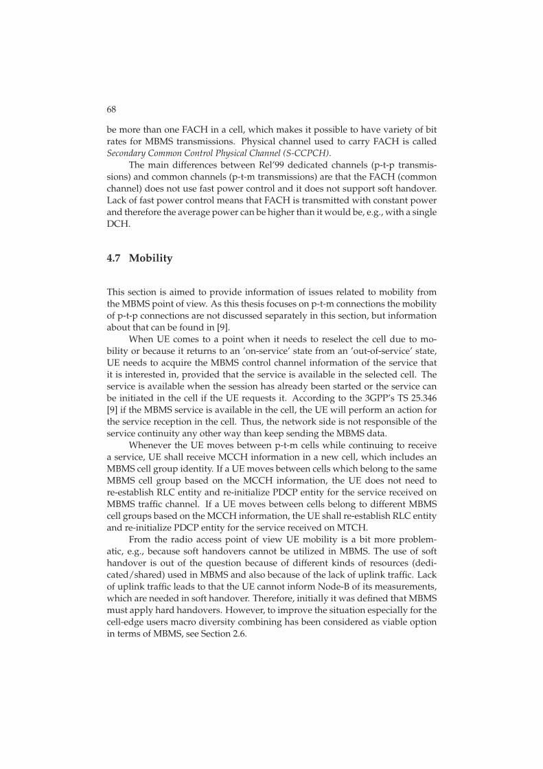
68
be more than one FACH in a cell, which makes it possible to have variety of bitrates for MBMS transmissions. Physical channel used to carry FACH is calledSecondary Common Control Physical Channel (S-CCPCH).
The main differences between Rel’99 dedicated channels (p-t-p transmis-sions) and common channels (p-t-m transmissions) are that the FACH (commonchannel) does not use fast power control and it does not support soft handover.Lack of fast power control means that FACH is transmitted with constant powerand therefore the average power can be higher than it would be, e.g., with a singleDCH.
4.7 Mobility
This section is aimed to provide information of issues related to mobility fromthe MBMS point of view. As this thesis focuses on p-t-m connections the mobilityof p-t-p connections are not discussed separately in this section, but informationabout that can be found in [9].
When UE comes to a point when it needs to reselect the cell due to mo-bility or because it returns to an ’on-service’ state from an ’out-of-service’ state,UE needs to acquire the MBMS control channel information of the service thatit is interested in, provided that the service is available in the selected cell. Theservice is available when the session has already been started or the service canbe initiated in the cell if the UE requests it. According to the 3GPP’s TS 25.346[9] if the MBMS service is available in the cell, the UE will perform an action forthe service reception in the cell. Thus, the network side is not responsible of theservice continuity any other way than keep sending the MBMS data.
Whenever the UE moves between p-t-m cells while continuing to receivea service, UE shall receive MCCH information in a new cell, which includes anMBMS cell group identity. If a UE moves between cells which belong to the sameMBMS cell group based on the MCCH information, the UE does not need tore-establish RLC entity and re-initialize PDCP entity for the service received onMBMS traffic channel. If a UE moves between cells belong to different MBMScell groups based on the MCCH information, the UE shall re-establish RLC entityand re-initialize PDCP entity for the service received on MTCH.
From the radio access point of view UE mobility is a bit more problem-atic, e.g., because soft handovers cannot be utilized in MBMS. The use of softhandover is out of the question because of different kinds of resources (dedi-cated/shared) used in MBMS and also because of the lack of uplink traffic. Lackof uplink traffic leads to that the UE cannot inform Node-B of its measurements,which are needed in soft handover. Therefore, initially it was defined that MBMSmust apply hard handovers. However, to improve the situation especially for thecell-edge users macro diversity combining has been considered as viable optionin terms of MBMS, see Section 2.6.
5 VOICE OVER IP
Voice over Internet Protocol is commonly referred as technology that includesonly the transportation of speech over packet switched networks. However, inreality VoIP covers not only speech but many value added services combinationof which could be referred as rich calls. Speech or voice is indeed the main ser-vice but VoIP employs the possibility for video feed, presence information, in-stant messaging and others. Even though VoIP brings a large variety of benefits,VoIP also introduces some challenges to tackle with. VoIP does not tolerate highlevel of packet loss, delays nor jitter (i.e., delay variance). These challenges canbe especially problematic in the perspective of wireless cellular networks. Thepurpose of this section is to shortly introduce VoIP, especially in terms of wirelesscellular networks.
5.1 Background
Voice over IP or VoIP protocols were used to carry voice signals over the earlyinternet for the first time in 1973. Those trials were for non-commercial use andthe first commercial software for end-users was made available much later in themid 1990’s. Company called Vocaltec released software called ’Internet Phone’ in1995 which did not still allow gateway to analog networks but communicationbetween other ’Internet Phone’ users was possible. Other competing companiesthat were working on similar products introduced their solutions subsequently.These included Nuera, Net2phone, Cisco, Clarent, Vienna Systems, etc. At thelate 90’s after the possibility to make also digital to analogue calls VoIP was get-ting more and more popular as people where able to make, e.g., internationalcalls with fraction of the cost of traditional calls.
VoIP-trend from the fixed networks is nowadays starting to emerge also inthe wireless cellular networks as the evolution of packet data technologies hasmade it possible to carry the voice efficiently over packet switched domain in-stead of traditional circuit switched solutions. In addition to mere technology,
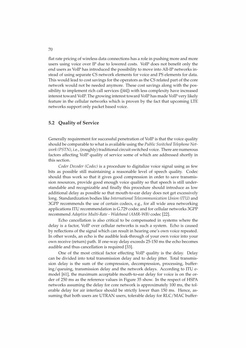
70
flat rate pricing of wireless data connections has a role in pushing more and moreusers using voice over IP due to lowered costs. VoIP does not benefit only theend users as VoIP has introduced the possibility to move into All-IP networks in-stead of using separate CS network elements for voice and PS elements for data.This would lead to cost savings for the operators as the CS related part of the corenetwork would not be needed anymore. These cost savings along with the pos-sibility to implement rich call services ([44]) with less complexity have increasedinterest toward VoIP. The growing interest toward VoIP has made VoIP very likelyfeature in the cellular networks which is proven by the fact that upcoming LTEnetworks support only packet based voice.
5.2 Quality of Service
Generally requirement for successful penetration of VoIP is that the voice qualityshould be comparable to what is available using the Public Switched Telephone Net-work (PSTN), i.e., (roughly) traditional circuit switched voice. There are numerousfactors affecting VoIP quality of service some of which are addressed shortly inthis section.
Coder Decoder (Codec) is a procedure to digitalize voice signal using as fewbits as possible still maintaining a reasonable level of speech quality. Codecshould thus work so that it gives good compression in order to save transmis-sion resources, provide good enough voice quality so that speech is still under-standable and recognizable and finally this procedure should introduce as lowadditional delay as possible so that mouth-to-ear delay does not get excessivelylong. Standardization bodies like International Telecommunication Union (ITU) and3GPP recommends the use of certain codecs, e.g., for all wide area networkingapplications ITU recommendation is G.729 codec and for cellular networks 3GPPrecommend Adaptive Multi-Rate - Wideband (AMR-WB) codec [22].
Echo cancellation is also critical to be compensated in systems where thedelay is a factor, VoIP over cellular networks is such a system. Echo is causedby reflections of the signal which can result in hearing one’s own voice repeated.In other words, an echo is the audible leak-through of your own voice into yourown receive (return) path. If one-way delay exceeds 25-150 ms the echo becomesaudible and thus cancellation is required [33].
One of the most critical factor effecting VoIP quality is the delay. Delaycan be divided into total transmission delay and to delay jitter. Total transmis-sion delay is the sum of the compression, decompression, processing, buffer-ing/queuing, transmission delay and the network delays. According to ITU e-model [61], the maximum acceptable mouth-to-ear delay for voice is on the or-der of 250 ms as the reference values in Figure 35 show. In the respect of HSPAnetworks assuming the delay for core network is approximately 100 ms, the tol-erable delay for air interface should be strictly lower than 150 ms. Hence, as-suming that both users are UTRAN users, tolerable delay for RLC/MAC buffer-
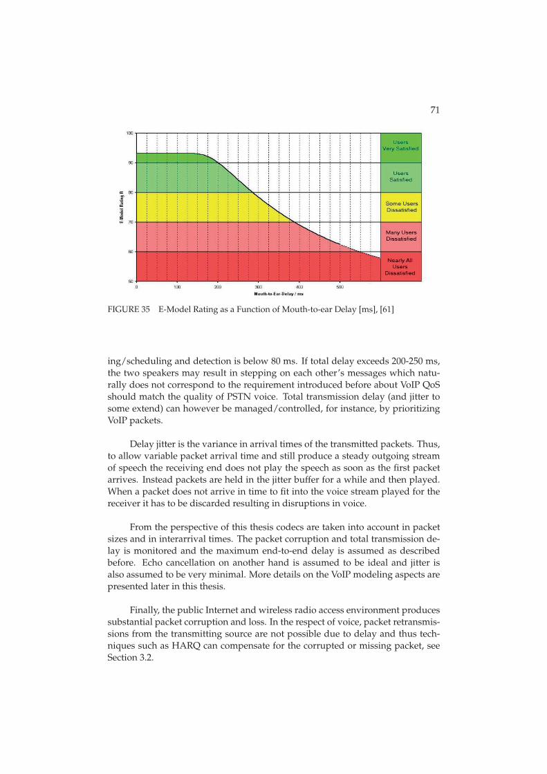
71
FIGURE 35 E-Model Rating as a Function of Mouth-to-ear Delay [ms], [61]
ing/scheduling and detection is below 80 ms. If total delay exceeds 200-250 ms,the two speakers may result in stepping on each other’s messages which natu-rally does not correspond to the requirement introduced before about VoIP QoSshould match the quality of PSTN voice. Total transmission delay (and jitter tosome extend) can however be managed/controlled, for instance, by prioritizingVoIP packets.
Delay jitter is the variance in arrival times of the transmitted packets. Thus,to allow variable packet arrival time and still produce a steady outgoing streamof speech the receiving end does not play the speech as soon as the first packetarrives. Instead packets are held in the jitter buffer for a while and then played.When a packet does not arrive in time to fit into the voice stream played for thereceiver it has to be discarded resulting in disruptions in voice.
From the perspective of this thesis codecs are taken into account in packetsizes and in interarrival times. The packet corruption and total transmission de-lay is monitored and the maximum end-to-end delay is assumed as describedbefore. Echo cancellation on another hand is assumed to be ideal and jitter isalso assumed to be very minimal. More details on the VoIP modeling aspects arepresented later in this thesis.
Finally, the public Internet and wireless radio access environment producessubstantial packet corruption and loss. In the respect of voice, packet retransmis-sions from the transmitting source are not possible due to delay and thus tech-niques such as HARQ can compensate for the corrupted or missing packet, seeSection 3.2.
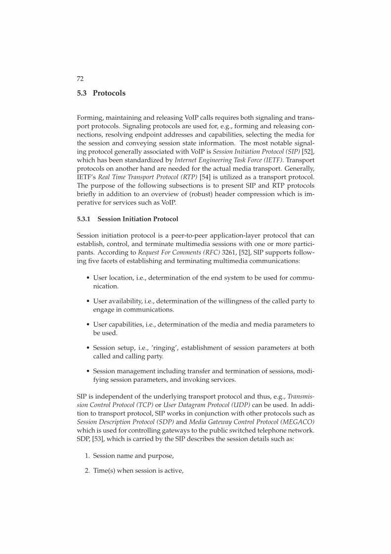
72
5.3 Protocols
Forming, maintaining and releasing VoIP calls requires both signaling and trans-port protocols. Signaling protocols are used for, e.g., forming and releasing con-nections, resolving endpoint addresses and capabilities, selecting the media forthe session and conveying session state information. The most notable signal-ing protocol generally associated with VoIP is Session Initiation Protocol (SIP) [52],which has been standardized by Internet Engineering Task Force (IETF). Transportprotocols on another hand are needed for the actual media transport. Generally,IETF’s Real Time Transport Protocol (RTP) [54] is utilized as a transport protocol.The purpose of the following subsections is to present SIP and RTP protocolsbriefly in addition to an overview of (robust) header compression which is im-perative for services such as VoIP.
5.3.1 Session Initiation Protocol
Session initiation protocol is a peer-to-peer application-layer protocol that canestablish, control, and terminate multimedia sessions with one or more partici-pants. According to Request For Comments (RFC) 3261, [52], SIP supports follow-ing five facets of establishing and terminating multimedia communications:
• User location, i.e., determination of the end system to be used for commu-nication.
• User availability, i.e., determination of the willingness of the called party toengage in communications.
• User capabilities, i.e., determination of the media and media parameters tobe used.
• Session setup, i.e., ’ringing’, establishment of session parameters at bothcalled and calling party.
• Session management including transfer and termination of sessions, modi-fying session parameters, and invoking services.
SIP is independent of the underlying transport protocol and thus, e.g., Transmis-sion Control Protocol (TCP) or User Datagram Protocol (UDP) can be used. In addi-tion to transport protocol, SIP works in conjunction with other protocols such asSession Description Protocol (SDP) and Media Gateway Control Protocol (MEGACO)which is used for controlling gateways to the public switched telephone network.SDP, [53], which is carried by the SIP describes the session details such as:
1. Session name and purpose,
2. Time(s) when session is active,
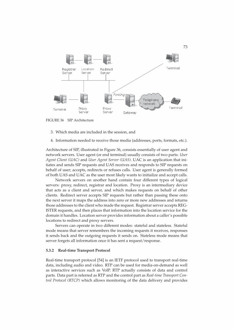
73
FIGURE 36 SIP Architecture
3. Which media are included in the session, and
4. Information needed to receive those media (addresses, ports, formats, etc.).
Architecture of SIP, illustrated in Figure 36, consists essentially of user agent andnetwork servers. User agent (or end terminal) usually consists of two parts: UserAgent Client (UAC) and User Agent Server (UAS). UAC is an application that ini-tiates and sends SIP requests and UAS receives and responds to SIP requests onbehalf of user; accepts, redirects or refuses calls. User agent is generally formedof both UAS and UAC as the user most likely wants to initialize and accept calls.
Network servers on another hand contain four different types of logicalservers: proxy, redirect, registrar and location. Proxy is an intermediary devicethat acts as a client and server, and which makes requests on behalf of otherclients. Redirect server accepts SIP requests but rather than passing these ontothe next server it maps the address into zero or more new addresses and returnsthose addresses to the client who made the request. Registrar server accepts REG-ISTER requests, and then places that information into the location service for thedomain it handles. Location server provides information about a caller’s possiblelocations to redirect and proxy servers.
Servers can operate in two different modes: stateful and stateless. Statefulmode means that server remembers the incoming requests it receives, responsesit sends back and the outgoing requests it sends on. Stateless mode means thatserver forgets all information once it has sent a request/response.
5.3.2 Real-time Transport Protocol
Real-time transport protocol [54] is an IETF protocol used to transport real-timedata, including audio and video. RTP can be used for media-on-demand as wellas interactive services such as VoIP. RTP actually consists of data and controlparts. Data part is referred as RTP and the control part as Real-time Transport Con-trol Protocol (RTCP) which allows monitoring of the data delivery and provides
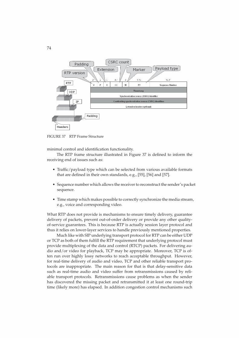
74
FIGURE 37 RTP Frame Structure
minimal control and identification functionality.The RTP frame structure illustrated in Figure 37 is defined to inform the
receiving end of issues such as:
• Traffic/payload type which can be selected from various available formatsthat are defined in their own standards, e.g., [55], [56] and [57].
• Sequence number which allows the receiver to reconstruct the sender’s packetsequence.
• Time stamp which makes possible to correctly synchronize the media stream,e.g., voice and corresponding video.
What RTP does not provide is mechanisms to ensure timely delivery, guaranteedelivery of packets, prevent out-of-order delivery or provide any other quality-of-service guarantees. This is because RTP is actually session layer protocol andthus it relies on lower-layer services to handle previously mentioned properties.
Much like with SIP underlying transport protocol for RTP can be either UDPor TCP as both of them fulfill the RTP requirement that underlying protocol mustprovide multiplexing of the data and control (RTCP) packets. For delivering au-dio and/or video for playback, TCP may be appropriate. Moreover, TCP is of-ten run over highly lossy networks to reach acceptable throughput. However,for real-time delivery of audio and video, TCP and other reliable transport pro-tocols are inappropriate. The main reason for that is that delay-sensitive datasuch as real-time audio and video suffer from retransmissions caused by reli-able transport protocols. Retransmissions cause problems as when the senderhas discovered the missing packet and retransmitted it at least one round-triptime (likely more) has elapsed. In addition congestion control mechanisms such
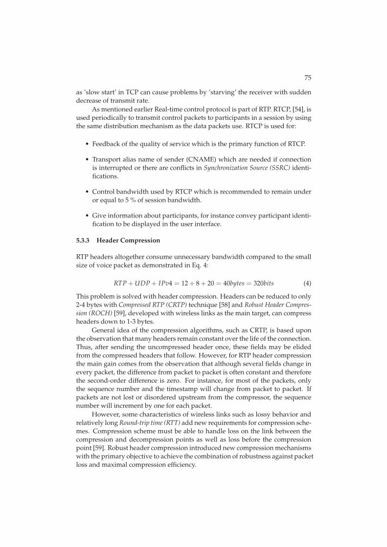
75
as ’slow start’ in TCP can cause problems by ’starving’ the receiver with suddendecrease of transmit rate.
As mentioned earlier Real-time control protocol is part of RTP. RTCP, [54], isused periodically to transmit control packets to participants in a session by usingthe same distribution mechanism as the data packets use. RTCP is used for:
• Feedback of the quality of service which is the primary function of RTCP.
• Transport alias name of sender (CNAME) which are needed if connectionis interrupted or there are conflicts in Synchronization Source (SSRC) identi-fications.
• Control bandwidth used by RTCP which is recommended to remain underor equal to 5 % of session bandwidth.
• Give information about participants, for instance convey participant identi-fication to be displayed in the user interface.
5.3.3 Header Compression
RTP headers altogether consume unnecessary bandwidth compared to the smallsize of voice packet as demonstrated in Eq. 4:
RTP + UDP + IPv4 = 12 + 8 + 20 = 40bytes = 320bits (4)
This problem is solved with header compression. Headers can be reduced to only2-4 bytes with Compressed RTP (CRTP) technique [58] and Robust Header Compres-sion (ROCH) [59], developed with wireless links as the main target, can compressheaders down to 1-3 bytes.
General idea of the compression algorithms, such as CRTP, is based uponthe observation that many headers remain constant over the life of the connection.Thus, after sending the uncompressed header once, these fields may be elidedfrom the compressed headers that follow. However, for RTP header compressionthe main gain comes from the observation that although several fields change inevery packet, the difference from packet to packet is often constant and thereforethe second-order difference is zero. For instance, for most of the packets, onlythe sequence number and the timestamp will change from packet to packet. Ifpackets are not lost or disordered upstream from the compressor, the sequencenumber will increment by one for each packet.
However, some characteristics of wireless links such as lossy behavior andrelatively long Round-trip time (RTT) add new requirements for compression sche-mes. Compression scheme must be able to handle loss on the link between thecompression and decompression points as well as loss before the compressionpoint [59]. Robust header compression introduced new compression mechanismswith the primary objective to achieve the combination of robustness against packetloss and maximal compression efficiency.
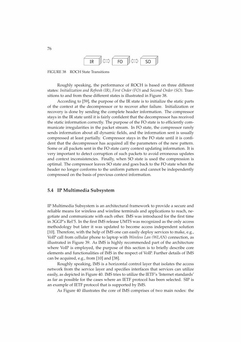
76
FIGURE 38 ROCH State Transitions
Roughly speaking, the performance of ROCH is based on three differentstates: Initialization and Refresh (IR), First Order (FO) and Second Order (SO). Tran-sitions to and from these different states is illustrated in Figure 38.
According to [59], the purpose of the IR state is to initialize the static partsof the context at the decompressor or to recover after failure. Initialization orrecovery is done by sending the complete header information. The compressorstays in the IR state until it is fairly confident that the decompressor has receivedthe static information correctly. The purpose of the FO state is to efficiently com-municate irregularities in the packet stream. In FO state, the compressor rarelysends information about all dynamic fields, and the information sent is usuallycompressed at least partially. Compressor stays in the FO state until it is confi-dent that the decompressor has acquired all the parameters of the new pattern.Some or all packets sent in the FO state carry context updating information. It isvery important to detect corruption of such packets to avoid erroneous updatesand context inconsistencies. Finally, when SO state is used the compression isoptimal. The compressor leaves SO state and goes back to the FO state when theheader no longer conforms to the uniform pattern and cannot be independentlycompressed on the basis of previous context information.
5.4 IP Multimedia Subsystem
IP Multimedia Subsystem is an architectural framework to provide a secure andreliable means for wireless and wireline terminals and applications to reach, ne-gotiate and communicate with each other. IMS was introduced for the first timein 3GGP’s Rel’5. In the first IMS release UMTS was recognized as the only accessmethodology but later it was updated to become access independent solution[10]. Therefore, with the help of IMS one can easily deploy services to make, e.g.,VoIP call from cellular phone to laptop with Wireless Lan (WLAN) connection, asillustrated in Figure 39. As IMS is highly recommended part of the architecturewhere VoIP is employed, the purpose of this section is to briefly describe coreelements and functionalities of IMS in the respect of VoIP. Further details of IMScan be acquired, e.g., from [10] and [38].
Roughly speaking, IMS is a horizontal control layer that isolates the accessnetwork from the service layer and specifies interfaces that services can utilizeeasily, as depicted in Figure 40. IMS tries to utilize the IETF’s ’Internet standards’as far as possible for the cases where an IETF protocol has been selected. SIP isan example of IETF protocol that is supported by IMS.
As Figure 40 illustrates the core of IMS comprises of two main nodes: the
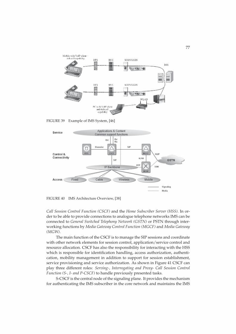
77
FIGURE 39 Example of IMS System, [46]
FIGURE 40 IMS Architecture Overview, [38]
Call Session Control Function (CSCF) and the Home Subscriber Server (HSS). In or-der to be able to provide connections to analogue telephone networks IMS can beconnected to General Switched Telephony Network (GSTN) or PSTN through inter-working functions by Media Gateway Control Function (MGCF) and Media Gateway(MGW).
The main function of the CSCF is to manage the SIP sessions and coordinatewith other network elements for session control, application/service control andresource allocation. CSCF has also the responsibility for interacting with the HSSwhich is responsible for identification handling, access authorization, authenti-cation, mobility management in addition to support for session establishment,service provisioning and service authorization. As shown in Figure 41 CSCF canplay three different roles: Serving-, Interrogating and Proxy- Call Session ControlFunction (S-, I- and P-CSCF) to handle previously presented tasks.
S-CSCF is the central node of the signaling plane. It provides the mechanismfor authenticating the IMS subscriber in the core network and maintains the IMS
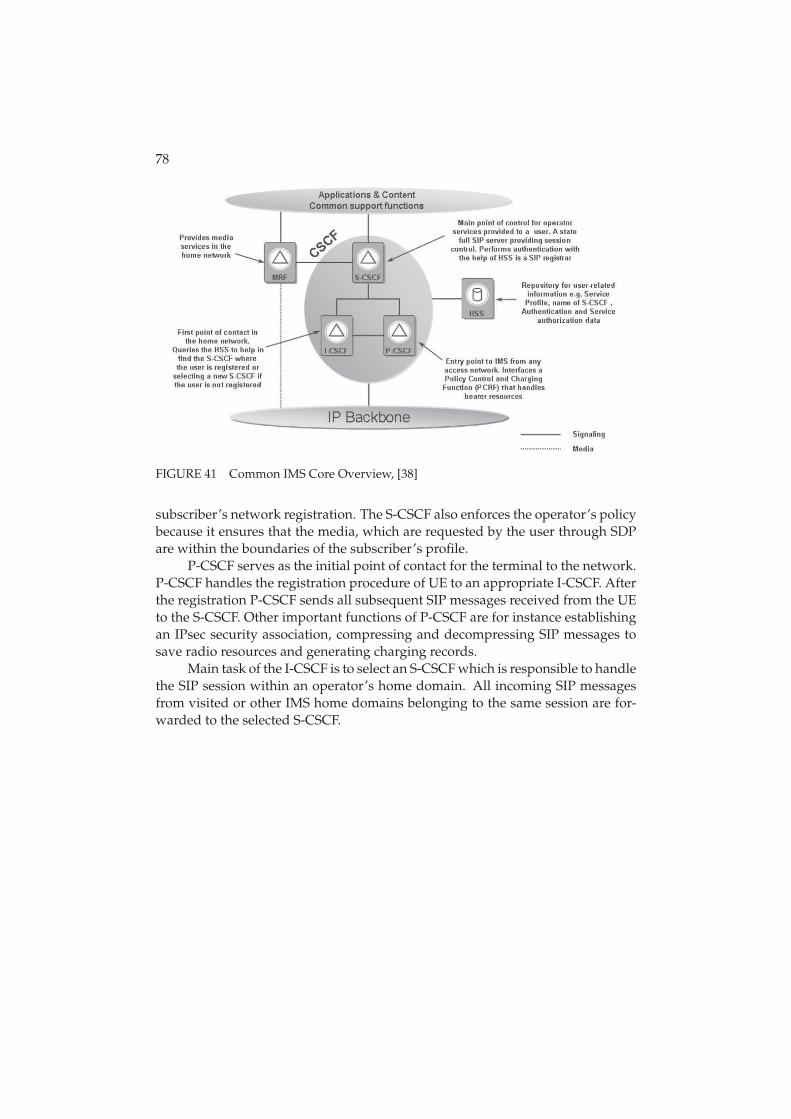
78
FIGURE 41 Common IMS Core Overview, [38]
subscriber’s network registration. The S-CSCF also enforces the operator’s policybecause it ensures that the media, which are requested by the user through SDPare within the boundaries of the subscriber’s profile.
P-CSCF serves as the initial point of contact for the terminal to the network.P-CSCF handles the registration procedure of UE to an appropriate I-CSCF. Afterthe registration P-CSCF sends all subsequent SIP messages received from the UEto the S-CSCF. Other important functions of P-CSCF are for instance establishingan IPsec security association, compressing and decompressing SIP messages tosave radio resources and generating charging records.
Main task of the I-CSCF is to select an S-CSCF which is responsible to handlethe SIP session within an operator’s home domain. All incoming SIP messagesfrom visited or other IMS home domains belonging to the same session are for-warded to the selected S-CSCF.
6 RESEARCH TOOLS
The research tools used to perform studies regarding this thesis are two com-prehensive system level radio network simulators. Simulators are designed forstudying RRM algorithms to obtain capacity and coverage estimates, to supportstandardization work and network planning by optimizing and tuning the ra-dio network parameters. Simulation tools enable detailed simulation of usersin multiple cells with realistic call generation, propagation and fading (adoptedfrom [21]).
There are at least two factors advocating the usage of system simulations:on the one hand, the complexity of the radio network behavior makes it virtuallyimpossible to calculate accurate analytical results, and on the other hand, phys-ical network trials would be time consuming and expensive. Thus, full systemlevel simulations where RRM functionalities and their inter-actions are taken ex-plicitly into account are essential to the performance evaluations. Moreover asthe used simulators are highly configurable with parameters for network traffic,user terminals, network configuration, RRM algorithms and physical layer in ad-dition to vast expandability possibilities those are truly indispensable tools forstudying radio network performance and enhancements.
The modeling and reliability analysis of the used system simulators havebeen presented earlier in many international articles and conferences, see, e.g.,[50], [83], [87] and [39] as well as in doctoral theses such as [69], [63] and [49].The reliability analysis of the tools is addressed in the Appendix 1 at the end ofthis thesis. The purpose of the following sections is to address modeling issuesbriefly with special focus on the aspects that this thesis addresses.
6.1 Simulator Types
Implementation of the used system level simulators themselves are a compromisebetween building an accurate model of a WCDMA/HSPA network and keepingmanageable computing efforts. In order to reduce the complexity and computa-
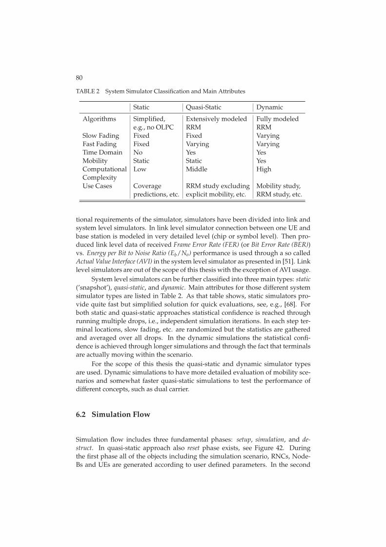
80
TABLE 2 System Simulator Classification and Main Attributes
Static Quasi-Static Dynamic
Algorithms Simplified, Extensively modeled Fully modelede.g., no OLPC RRM RRM
Slow Fading Fixed Fixed VaryingFast Fading Fixed Varying VaryingTime Domain No Yes YesMobility Static Static YesComputational Low Middle HighComplexityUse Cases Coverage RRM study excluding Mobility study,
predictions, etc. explicit mobility, etc. RRM study, etc.
tional requirements of the simulator, simulators have been divided into link andsystem level simulators. In link level simulator connection between one UE andbase station is modeled in very detailed level (chip or symbol level). Then pro-duced link level data of received Frame Error Rate (FER) (or Bit Error Rate (BER))vs. Energy per Bit to Noise Ratio (Eb/No) performance is used through a so calledActual Value Interface (AVI) in the system level simulator as presented in [51]. Linklevel simulators are out of the scope of this thesis with the exception of AVI usage.
System level simulators can be further classified into three main types: static(’snapshot’), quasi-static, and dynamic. Main attributes for those different systemsimulator types are listed in Table 2. As that table shows, static simulators pro-vide quite fast but simplified solution for quick evaluations, see, e.g., [68]. Forboth static and quasi-static approaches statistical confidence is reached throughrunning multiple drops, i.e., independent simulation iterations. In each step ter-minal locations, slow fading, etc. are randomized but the statistics are gatheredand averaged over all drops. In the dynamic simulations the statistical confi-dence is achieved through longer simulations and through the fact that terminalsare actually moving within the scenario.
For the scope of this thesis the quasi-static and dynamic simulator typesare used. Dynamic simulations to have more detailed evaluation of mobility sce-narios and somewhat faster quasi-static simulations to test the performance ofdifferent concepts, such as dual carrier.
6.2 Simulation Flow
Simulation flow includes three fundamental phases: setup, simulation, and de-struct. In quasi-static approach also reset phase exists, see Figure 42. Duringthe first phase all of the objects including the simulation scenario, RNCs, Node-Bs and UEs are generated according to user defined parameters. In the second
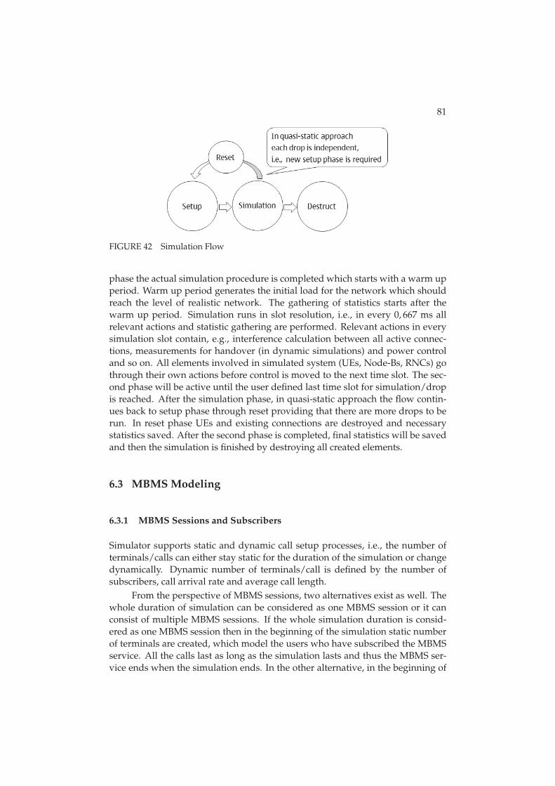
81
FIGURE 42 Simulation Flow
phase the actual simulation procedure is completed which starts with a warm upperiod. Warm up period generates the initial load for the network which shouldreach the level of realistic network. The gathering of statistics starts after thewarm up period. Simulation runs in slot resolution, i.e., in every 0, 667 ms allrelevant actions and statistic gathering are performed. Relevant actions in everysimulation slot contain, e.g., interference calculation between all active connec-tions, measurements for handover (in dynamic simulations) and power controland so on. All elements involved in simulated system (UEs, Node-Bs, RNCs) gothrough their own actions before control is moved to the next time slot. The sec-ond phase will be active until the user defined last time slot for simulation/dropis reached. After the simulation phase, in quasi-static approach the flow contin-ues back to setup phase through reset providing that there are more drops to berun. In reset phase UEs and existing connections are destroyed and necessarystatistics saved. After the second phase is completed, final statistics will be savedand then the simulation is finished by destroying all created elements.
6.3 MBMS Modeling
6.3.1 MBMS Sessions and Subscribers
Simulator supports static and dynamic call setup processes, i.e., the number ofterminals/calls can either stay static for the duration of the simulation or changedynamically. Dynamic number of terminals/call is defined by the number ofsubscribers, call arrival rate and average call length.
From the perspective of MBMS sessions, two alternatives exist as well. Thewhole duration of simulation can be considered as one MBMS session or it canconsist of multiple MBMS sessions. If the whole simulation duration is consid-ered as one MBMS session then in the beginning of the simulation static numberof terminals are created, which model the users who have subscribed the MBMSservice. All the calls last as long as the simulation lasts and thus the MBMS ser-vice ends when the simulation ends. In the other alternative, in the beginning of
82
the simulation static number of terminals are created, which again presents theusers who have subscribed to MBMS service. Fixed MBMS service duration, i.e.,call duration is defined for each terminal. All calls end at the same time, thus thenew MBMS service and the new calls start immediately after the previous servicehas ended. Similar simulation scenarios can be applied to dynamic number ofsubscribers as well. This thesis assumes static number of terminals and multi-ple MBMS sessions during one simulation run in order to guarantee satisfactorynumber of samples to analyze the results.
6.3.2 MBMS Transmission and Reception
For each sector MTCH is created and it has a constant transmit power. MTCH’spower is thus taken into account in interference calculations. MTCH is modeledsimilarly as Common Pilot Channel (CPICH), i.e., only the transmitter, i.e., Node-Bside is defined for that channel. Certain power allocation can also be reservedfor MCCH. However, in these studies MCCH power is assumed to be part of theother common channels.
Reception of MTCH data can be done from a single or multiple cells/sectorsto model soft and selective combining which were presented in Section 2.6. If thereception is done from multiple cells/sectors those cells/sectors are referred ascombining set. Combining set update procedure for MBMS p-t-m transmissionsis much like the ordinary soft handover, see Section 2.9.3. The difference to softhandover is that the UE does not send any measurement reports to the networkside but independently decides, according to filtered pilot measurements, fromwhich sectors it receives and combines signals. Due to the fact that combining setupdate procedure is very much like soft handover same terminology is used inthis thesis when concerning issues related to the combining set update procedure.Parameterized delay is also modeled for combining set updates, i.e., combiningset update events are held in the delay queue according to delay parameter beforeactual combining set update is done.
6.4 VoIP Modeling
Following subsections describe how VoIP specific issues presented in Section 5are taken into account in the used simulators. The main focus of the modeling ison the radio network interface and related issues.
6.4.1 VoIP Traffic
The VoIP traffic model that is assumed in this thesis is illustrated in Figure 43.The main parameters of the feature are presented in Table 3 and described in thefollowing:
• Duration of each call is random and distributed according to negative ex-
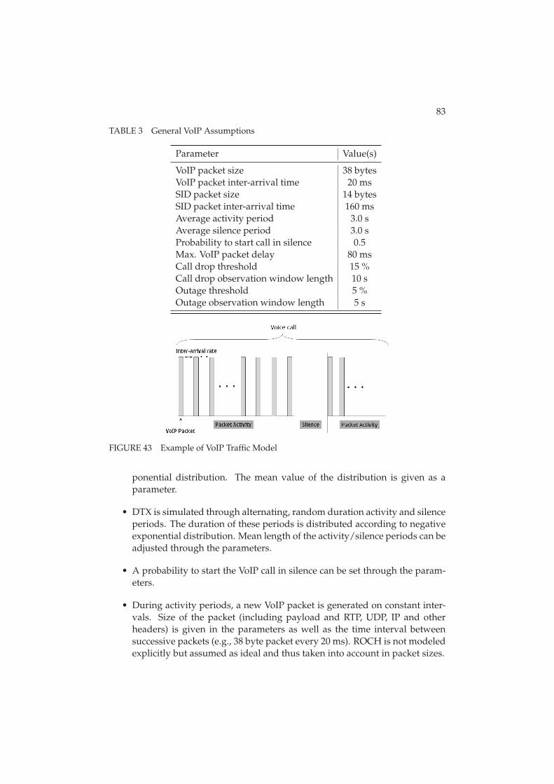
83
TABLE 3 General VoIP Assumptions
Parameter Value(s)
VoIP packet size 38 bytesVoIP packet inter-arrival time 20 msSID packet size 14 bytesSID packet inter-arrival time 160 msAverage activity period 3.0 sAverage silence period 3.0 sProbability to start call in silence 0.5Max. VoIP packet delay 80 msCall drop threshold 15 %Call drop observation window length 10 sOutage threshold 5 %Outage observation window length 5 s
FIGURE 43 Example of VoIP Traffic Model
ponential distribution. The mean value of the distribution is given as aparameter.
• DTX is simulated through alternating, random duration activity and silenceperiods. The duration of these periods is distributed according to negativeexponential distribution. Mean length of the activity/silence periods can beadjusted through the parameters.
• A probability to start the VoIP call in silence can be set through the param-eters.
• During activity periods, a new VoIP packet is generated on constant inter-vals. Size of the packet (including payload and RTP, UDP, IP and otherheaders) is given in the parameters as well as the time interval betweensuccessive packets (e.g., 38 byte packet every 20 ms). ROCH is not modeledexplicitly but assumed as ideal and thus taken into account in packet sizes.
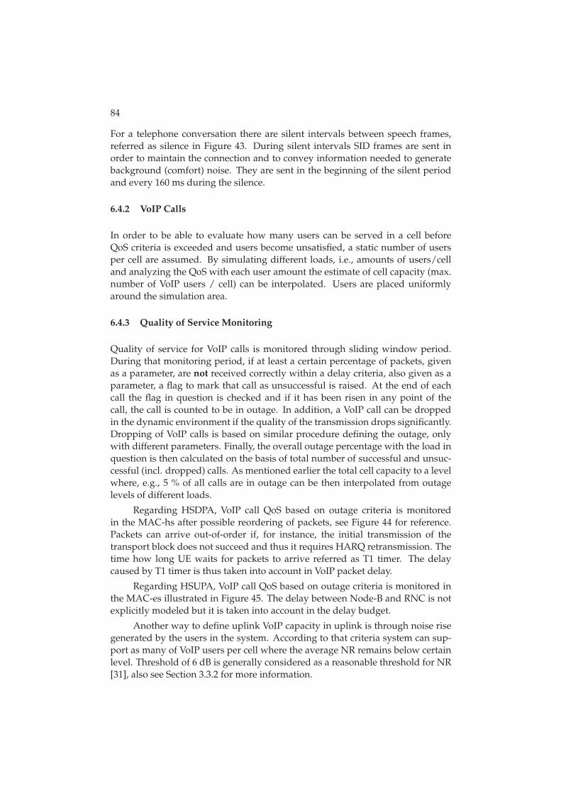
84
For a telephone conversation there are silent intervals between speech frames,referred as silence in Figure 43. During silent intervals SID frames are sent inorder to maintain the connection and to convey information needed to generatebackground (comfort) noise. They are sent in the beginning of the silent periodand every 160 ms during the silence.
6.4.2 VoIP Calls
In order to be able to evaluate how many users can be served in a cell beforeQoS criteria is exceeded and users become unsatisfied, a static number of usersper cell are assumed. By simulating different loads, i.e., amounts of users/celland analyzing the QoS with each user amount the estimate of cell capacity (max.number of VoIP users / cell) can be interpolated. Users are placed uniformlyaround the simulation area.
6.4.3 Quality of Service Monitoring
Quality of service for VoIP calls is monitored through sliding window period.During that monitoring period, if at least a certain percentage of packets, givenas a parameter, are not received correctly within a delay criteria, also given as aparameter, a flag to mark that call as unsuccessful is raised. At the end of eachcall the flag in question is checked and if it has been risen in any point of thecall, the call is counted to be in outage. In addition, a VoIP call can be droppedin the dynamic environment if the quality of the transmission drops significantly.Dropping of VoIP calls is based on similar procedure defining the outage, onlywith different parameters. Finally, the overall outage percentage with the load inquestion is then calculated on the basis of total number of successful and unsuc-cessful (incl. dropped) calls. As mentioned earlier the total cell capacity to a levelwhere, e.g., 5 % of all calls are in outage can be then interpolated from outagelevels of different loads.
Regarding HSDPA, VoIP call QoS based on outage criteria is monitoredin the MAC-hs after possible reordering of packets, see Figure 44 for reference.Packets can arrive out-of-order if, for instance, the initial transmission of thetransport block does not succeed and thus it requires HARQ retransmission. Thetime how long UE waits for packets to arrive referred as T1 timer. The delaycaused by T1 timer is thus taken into account in VoIP packet delay.
Regarding HSUPA, VoIP call QoS based on outage criteria is monitored inthe MAC-es illustrated in Figure 45. The delay between Node-B and RNC is notexplicitly modeled but it is taken into account in the delay budget.
Another way to define uplink VoIP capacity in uplink is through noise risegenerated by the users in the system. According to that criteria system can sup-port as many of VoIP users per cell where the average NR remains below certainlevel. Threshold of 6 dB is generally considered as a reasonable threshold for NR[31], also see Section 3.3.2 for more information.
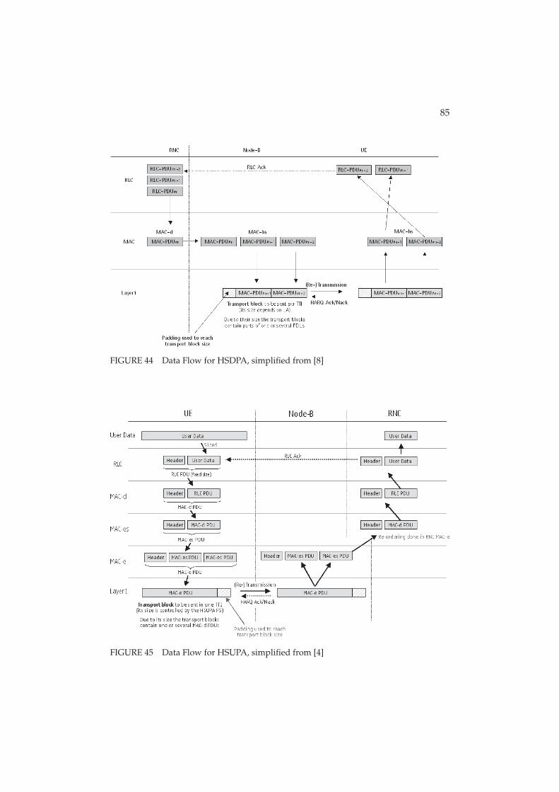
85
FIGURE 44 Data Flow for HSDPA, simplified from [8]
FIGURE 45 Data Flow for HSUPA, simplified from [4]
86
6.5 Interference Coordination Modeling
Interference coordination for HSUPA is implemented to quasi-static simulator astime domain coordination following the principles presented in Section 3.7. Thebase stations and scheduling functionalities are synchronized so that in certaincells only the cell edge users transmit while in the neighboring cells cell centerperiod is in turn. For the purpose of the simulations, 9 HARQ processes areassumed as it allows a straightforward division of the HARQ processes into threegroups, and application of a re-use pattern of 3 shown in Figure 25.
6.6 Dual Carrier Modeling
Dual carrier is modeled to quasi-static simulator as well in accordance to theconcept presented in Section 3.8. Modeling includes, e.g., in addition to E-DCHDPCCH for all carriers to keep the power control and related actions up to datefor all carries. Additional DPCCHs bring some overhead (interference) to the sys-tem which is thus taken into account. Rate requests, scheduling, retransmissions(always on the same carrier), etc. are also modeled in detail for the simulator.
7 ACHIEVED RESULTS
The objective of this chapter is to first present study scenarios and assumptionsused with the research tools introduced in Chapter 6. Scenarios and assumptionsare then followed by the result analysis.
7.1 Simulation Scenarios
The studies presented in this thesis are based on various different network lay-outs. Macro scenarios range from hexagonal cellular environment to a perfor-mance analysis in non-regular network layout. In addition to macro scenariosthis thesis addresses the performance in manhattan scenario as well.
Majority of the simulative studies are conducted in hexagonal macro cellu-lar scenarios. Most of the macro scenarios are utilizing Wrap-Around (WA). Thepurpose of the wrap-around is to model the interference correctly also for outercells. This is achieved by limiting the UE mobility / placement around the actualsimulation area but replicating the cell transmissions around the whole simula-tion area to offer more realistic interference situation throughout the scenario. AUE is able to make a handover to the outer cells but if it moves outside the mo-bility area, its position is moved to the opposite side of the mobility area.
In this thesis two different WA layouts are applied: one with 21 cells and 7base stations and another with tier type of a structure. In latter WA scenario, twotiers results into 21 cells and 7 BSs and three tiers into 57 cells and 19 BSs. Figure46 depicts the cellular structure of the first wrap-around scenario and Figure 47depicts the actual simulation area of the latter.
VoIP over HSDPA simulations presented in article [PV], were initially basedon scenario with 18 cells and 9 base stations without wrap-around. That scenariois illustrated in Figure 48. This thesis broadens that article slightly by providingcomparison of those results into re-simulated results in a WA scenario to exclude,e.g., the impact of border-effects.
Figure 49 illustrates the non-regular macro scenario. Unlike with other sce-
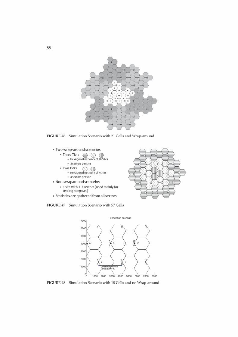
88
FIGURE 46 Simulation Scenario with 21 Cells and Wrap-around
FIGURE 47 Simulation Scenario with 57 Cells
0 1000 2000 3000 4000 5000 6000 7000 80000
1000
2000
3000
4000
5000
6000
7000
0
12
3
4
56
7
89
10
11
1213
14
15
16
17
Simulation scenario
Distance betweenBSs is 2800 m
FIGURE 48 Simulation Scenario with 18 Cells and no Wrap-around
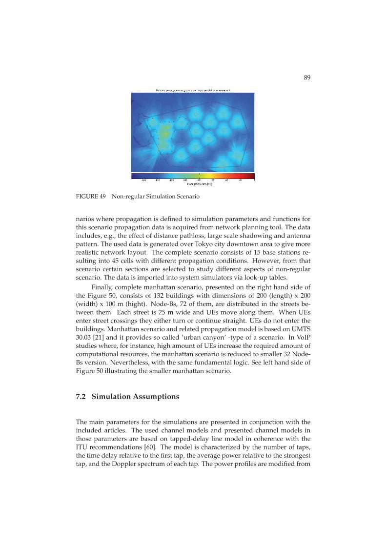
89
FIGURE 49 Non-regular Simulation Scenario
narios where propagation is defined to simulation parameters and functions forthis scenario propagation data is acquired from network planning tool. The dataincludes, e.g., the effect of distance pathloss, large scale shadowing and antennapattern. The used data is generated over Tokyo city downtown area to give morerealistic network layout. The complete scenario consists of 15 base stations re-sulting into 45 cells with different propagation conditions. However, from thatscenario certain sections are selected to study different aspects of non-regularscenario. The data is imported into system simulators via look-up tables.
Finally, complete manhattan scenario, presented on the right hand side ofthe Figure 50, consists of 132 buildings with dimensions of 200 (length) x 200(width) x 100 m (hight). Node-Bs, 72 of them, are distributed in the streets be-tween them. Each street is 25 m wide and UEs move along them. When UEsenter street crossings they either turn or continue straight. UEs do not enter thebuildings. Manhattan scenario and related propagation model is based on UMTS30.03 [21] and it provides so called ’urban canyon’ -type of a scenario. In VoIPstudies where, for instance, high amount of UEs increase the required amount ofcomputational resources, the manhattan scenario is reduced to smaller 32 Node-Bs version. Nevertheless, with the same fundamental logic. See left hand side ofFigure 50 illustrating the smaller manhattan scenario.
7.2 Simulation Assumptions
The main parameters for the simulations are presented in conjunction with theincluded articles. The used channel models and presented channel models inthose parameters are based on tapped-delay line model in coherence with theITU recommendations [60]. The model is characterized by the number of taps,the time delay relative to the first tap, the average power relative to the strongesttap, and the Doppler spectrum of each tap. The power profiles are modified from
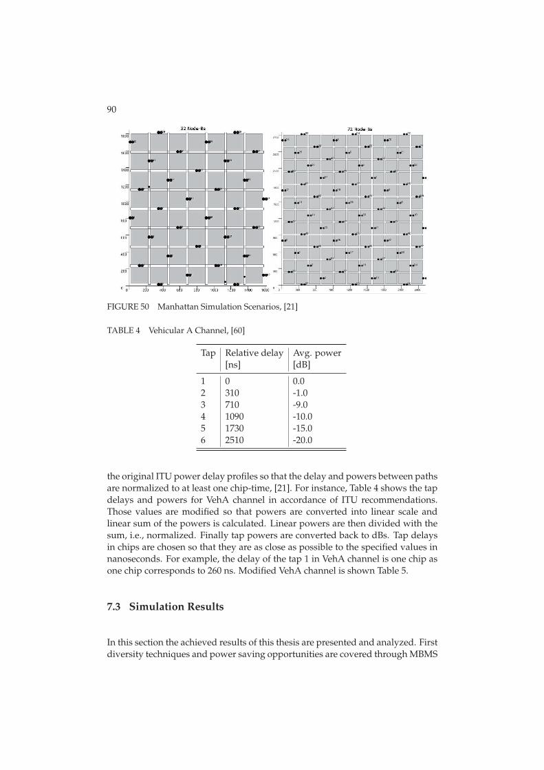
90
FIGURE 50 Manhattan Simulation Scenarios, [21]
TABLE 4 Vehicular A Channel, [60]
Tap Relative delay Avg. power[ns] [dB]
1 0 0.02 310 -1.03 710 -9.04 1090 -10.05 1730 -15.06 2510 -20.0
the original ITU power delay profiles so that the delay and powers between pathsare normalized to at least one chip-time, [21]. For instance, Table 4 shows the tapdelays and powers for VehA channel in accordance of ITU recommendations.Those values are modified so that powers are converted into linear scale andlinear sum of the powers is calculated. Linear powers are then divided with thesum, i.e., normalized. Finally tap powers are converted back to dBs. Tap delaysin chips are chosen so that they are as close as possible to the specified values innanoseconds. For example, the delay of the tap 1 in VehA channel is one chip asone chip corresponds to 260 ns. Modified VehA channel is shown Table 5.
7.3 Simulation Results
In this section the achieved results of this thesis are presented and analyzed. Firstdiversity techniques and power saving opportunities are covered through MBMS
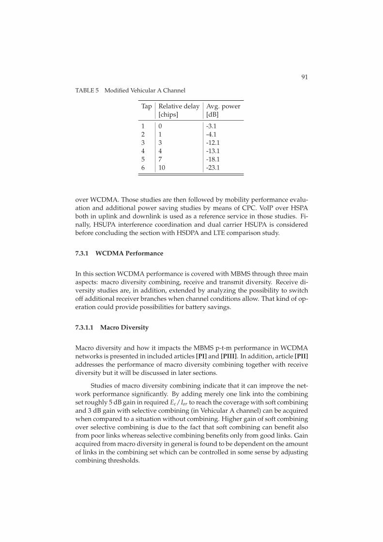
91
TABLE 5 Modified Vehicular A Channel
Tap Relative delay Avg. power[chips] [dB]
1 0 -3.12 1 -4.13 3 -12.14 4 -13.15 7 -18.16 10 -23.1
over WCDMA. Those studies are then followed by mobility performance evalu-ation and additional power saving studies by means of CPC. VoIP over HSPAboth in uplink and downlink is used as a reference service in those studies. Fi-nally, HSUPA interference coordination and dual carrier HSUPA is consideredbefore concluding the section with HSDPA and LTE comparison study.
7.3.1 WCDMA Performance
In this section WCDMA performance is covered with MBMS through three mainaspects: macro diversity combining, receive and transmit diversity. Receive di-versity studies are, in addition, extended by analyzing the possibility to switchoff additional receiver branches when channel conditions allow. That kind of op-eration could provide possibilities for battery savings.
7.3.1.1 Macro Diversity
Macro diversity and how it impacts the MBMS p-t-m performance in WCDMAnetworks is presented in included articles [PI] and [PIII]. In addition, article [PII]addresses the performance of macro diversity combining together with receivediversity but it will be discussed in later sections.
Studies of macro diversity combining indicate that it can improve the net-work performance significantly. By adding merely one link into the combiningset roughly 5 dB gain in required Ec/Ior to reach the coverage with soft combiningand 3 dB gain with selective combining (in Vehicular A channel) can be acquiredwhen compared to a situation without combining. Higher gain of soft combiningover selective combining is due to the fact that soft combining can benefit alsofrom poor links whereas selective combining benefits only from good links. Gainacquired from macro diversity in general is found to be dependent on the amountof links in the combining set which can be controlled in some sense by adjustingcombining thresholds.
92
7.3.1.2 Receive Diversity and Battery Savings
Performance enhancement studies in WCDMA networks are extended in arti-cles [PII] and [PIII] to cover the situation where (MBMS) terminals would bedeployed with two receive antennas instead of just one. Traditionally multipleantennas have not been employed in smallest handheld devices due to size andcost constraints. However, receive diversity is one of the most efficient diversitytechniques, since in addition to the diversity gain the received combined signalpower is theoretically doubled with two receive antennas when compared to sin-gle antenna reception.
Simulation results show that receive diversity can bring substantial benefitfor MBMS transmissions. The gain of 2 Rx receive diversity over 1 Rx is roughly 4dB in terms of in required Ec/Ior depending on the other simulation parameters.Moreover, the results show that even if terminals would be able to utilize receivediversity macro diversity combining still brings quite a significant gain to theperformance.
When network is dimensioned for terminals with only one receive antenna(no Rx diversity) and the system contains also 2 Rx terminals the power savingsopportunities can in theory be accomplished by switching off additional receiverbranches when radio conditions allow. Article [PIII] studies possible power sav-ing opportunities in such situations.
The study demonstrates that it is indeed possible to achieve very similarcoverage levels in situations where 2 Rx UEs are either allowed to reconfigurebetween 1 Rx Rake and 2 Rx Rake receiver or to use only 2 Rx Rake receiver.To achieve this goal in terms of coverage levels one only needs to have suitableswitching thresholds and C/I filtering windows in use. Apart from network per-formance, antenna usage statistics indicate that there is a possibility that the 1 RxRake configuration is used for a significant amount of time. Thus, there are defi-nitely power saving opportunities relative to UEs using 2 Rx Rake continuously.
7.3.1.3 Transmit Diversity
Finally, transmit diversity is also considered as one way to improve the systemcapacity and performance. Tx diversity exploits the principle of providing thereceiver with multiple faded replicas of the same information-bearing signal. Theimpact of Tx diversity together with MBMS is studied in article [PIII].
The results of that study show that transmit diversity narrows Es/No distri-bution and provides slight improvement to lower tail of Es/No distribution withand without soft combining. In terms of coverage this slight improvement leadsto around 2 dB gain without combining. The gain is reduced to less than 1.5 dBwith soft combining due to the presence of additional source for diversity.
93
7.3.2 HSDPA Performance
In this section downlink performance over high speed packet access networksis studied in terms of mobility and battery savings with VoIP service. Mobil-ity related aspects are covered in articles [PV], [PVI] and [PV]. Battery savingsare addressed through discontinuous reception in article [PVII]. In addition, inarticle [PXI] VoIP over HSDPA performance is addressed in comparison to LTEdownlink performance but that article is discussed later in Section 7.3.4.
7.3.2.1 Mobility
The fact that HSDPA is supporting only hard handover can result into excessivepacket losses and delays if handovers are not executed in time or contrary areexecuted too often. The impact of serving HS-DSCH cell change procedure alongwith different user velocities and cell change execution delays was addressed inarticle [PV]. The probability of signaling radio bearer reception is further investi-gated in [PVI] by means of dynamic simulations in macro and more demandingmanhattan scenarios. Finally, [PVIII] deepens the mobility studies through re-stricting the data transmission during the handover procedure and limiting themaximum number of terminals per cell.
The simulation results in article [PV] indicate, in general, moderate sensi-tivity of VoIP capacity to the UE velocity. Very high velocities lead to more no-ticeable capacity loss. However, fine-tuning handover parameters for differentvelocities can provide better performance but on the other hand in practice thatwould require some mechanisms for UE speed detection if it would be done dy-namically. In terms of handover delay it starts to have more significant impactonly at UE velocity of 50 km/h or more. Reliability of handover signaling, i.e.,situation where handover command is actually sent over the air is concluded notto pose problems.
A while after the article [PV] was published VoIP over HSDPA studies werere-opened for study, e.g., power consumption related matters. As quite a consid-erable amount of time had passed from the studies presented in article [PV] thesimulator had also undergone some updates. The updated version of the simu-lator includes more detailed modeling of mobility, HSDPA and VoIP to name afew. In addition, support for wrap-around scenario was provided along with theupdated version. Due to these changes, performance benchmarking between oldand revised results was made.
Comparison between updated results and the results presented in article[PV] is illustrated in Figure 51. As the figure shows the absolute capacity num-bers are somewhat improved with the updated simulator version. The increasedepends heavily on the user velocity which is mainly due to revised handoverand mobility operation in the updated simulator version. For instance, with 3km/h the capacity numbers are still in same order and the difference is only acouple of UEs/cell but for higher velocities the capacity is higher than before.Therefore, also the relative drop caused by user velocity is somewhat lower than
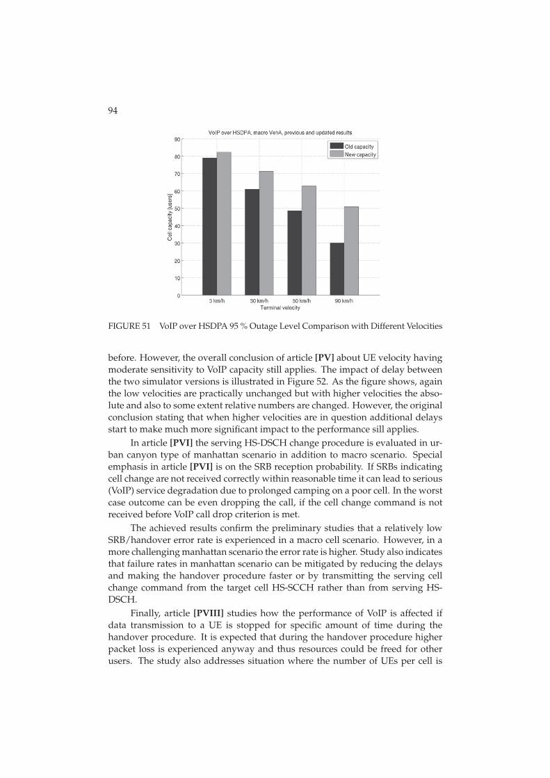
94
FIGURE 51 VoIP over HSDPA 95 % Outage Level Comparison with Different Velocities
before. However, the overall conclusion of article [PV] about UE velocity havingmoderate sensitivity to VoIP capacity still applies. The impact of delay betweenthe two simulator versions is illustrated in Figure 52. As the figure shows, againthe low velocities are practically unchanged but with higher velocities the abso-lute and also to some extent relative numbers are changed. However, the originalconclusion stating that when higher velocities are in question additional delaysstart to make much more significant impact to the performance sill applies.
In article [PVI] the serving HS-DSCH change procedure is evaluated in ur-ban canyon type of manhattan scenario in addition to macro scenario. Specialemphasis in article [PVI] is on the SRB reception probability. If SRBs indicatingcell change are not received correctly within reasonable time it can lead to serious(VoIP) service degradation due to prolonged camping on a poor cell. In the worstcase outcome can be even dropping the call, if the cell change command is notreceived before VoIP call drop criterion is met.
The achieved results confirm the preliminary studies that a relatively lowSRB/handover error rate is experienced in a macro cell scenario. However, in amore challenging manhattan scenario the error rate is higher. Study also indicatesthat failure rates in manhattan scenario can be mitigated by reducing the delaysand making the handover procedure faster or by transmitting the serving cellchange command from the target cell HS-SCCH rather than from serving HS-DSCH.
Finally, article [PVIII] studies how the performance of VoIP is affected ifdata transmission to a UE is stopped for specific amount of time during thehandover procedure. It is expected that during the handover procedure higherpacket loss is experienced anyway and thus resources could be freed for otherusers. The study also addresses situation where the number of UEs per cell is
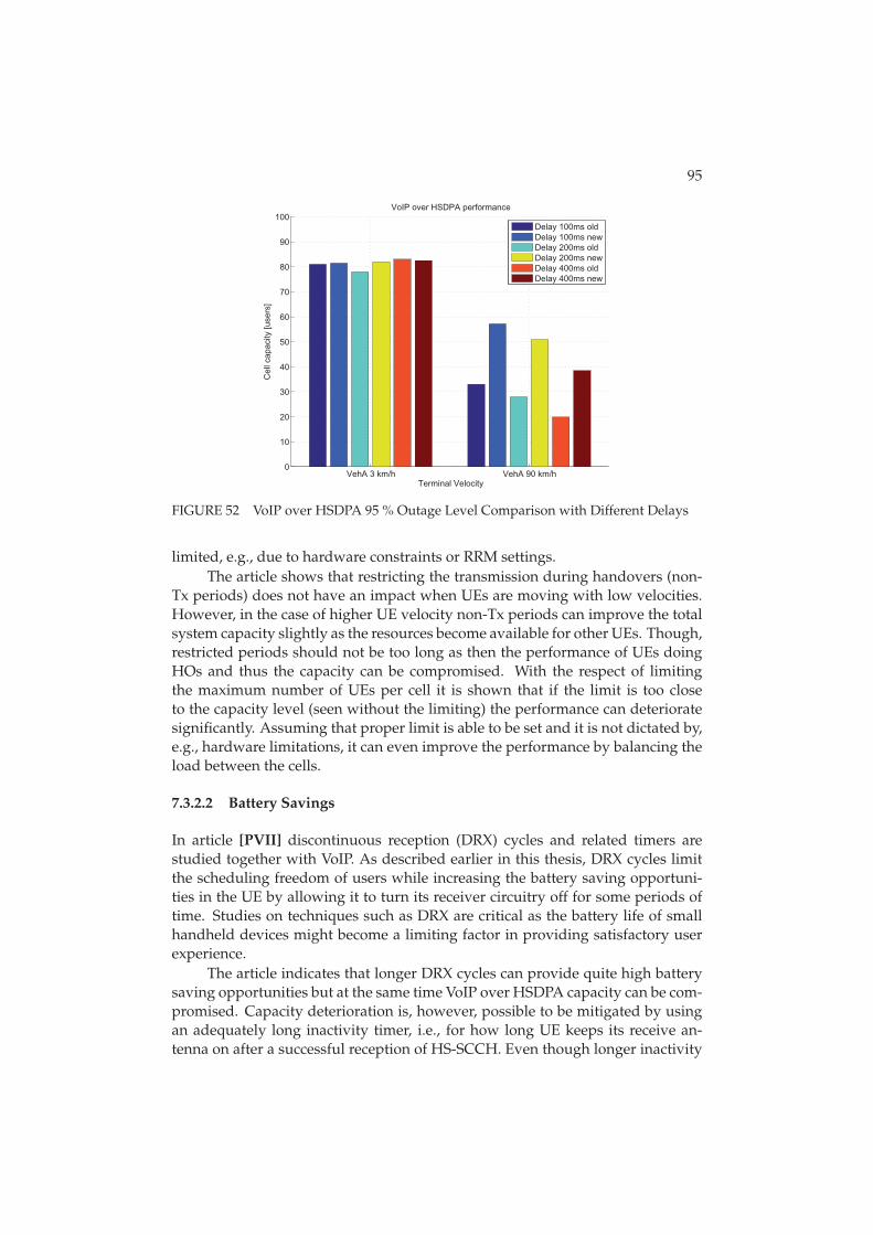
95
VehA 3 km/h VehA 90 km/h0
10
20
30
40
50
60
70
80
90
100
Terminal Velocity
Cel
l cap
acity
[use
rs]
VoIP over HSDPA performance
Delay 100ms oldDelay 100ms newDelay 200ms oldDelay 200ms newDelay 400ms oldDelay 400ms new
FIGURE 52 VoIP over HSDPA 95 % Outage Level Comparison with Different Delays
limited, e.g., due to hardware constraints or RRM settings.The article shows that restricting the transmission during handovers (non-
Tx periods) does not have an impact when UEs are moving with low velocities.However, in the case of higher UE velocity non-Tx periods can improve the totalsystem capacity slightly as the resources become available for other UEs. Though,restricted periods should not be too long as then the performance of UEs doingHOs and thus the capacity can be compromised. With the respect of limitingthe maximum number of UEs per cell it is shown that if the limit is too closeto the capacity level (seen without the limiting) the performance can deterioratesignificantly. Assuming that proper limit is able to be set and it is not dictated by,e.g., hardware limitations, it can even improve the performance by balancing theload between the cells.
7.3.2.2 Battery Savings
In article [PVII] discontinuous reception (DRX) cycles and related timers arestudied together with VoIP. As described earlier in this thesis, DRX cycles limitthe scheduling freedom of users while increasing the battery saving opportuni-ties in the UE by allowing it to turn its receiver circuitry off for some periods oftime. Studies on techniques such as DRX are critical as the battery life of smallhandheld devices might become a limiting factor in providing satisfactory userexperience.
The article indicates that longer DRX cycles can provide quite high batterysaving opportunities but at the same time VoIP over HSDPA capacity can be com-promised. Capacity deterioration is, however, possible to be mitigated by usingan adequately long inactivity timer, i.e., for how long UE keeps its receive an-tenna on after a successful reception of HS-SCCH. Even though longer inactivity
96
timer limits the power saving opportunities to some extend those are still quitesignificant.
7.3.3 HSUPA Performance
Uplink is most often considered to limit the overall coverage of services due tothe fact that uplink is characterized by power limited terminals and high inter-ference levels. Moreover, with certain service types, such as speech, the highnumber of simultaneous connections can put high strain on the radio network re-sources. Similarly to HSDPA, also mobility brings along its own challenges eventhough SHO is supported in HSUPA. In the following subsection these challengesare addressed. Firstly, mobility related aspects are addressed in dynamic systemlevel study presented in article [PIV]. That is followed by article [PXIII] coveringstudies on coverage extension and battery saving possibilities in the uplink. Arti-cles [PXII] and [PIX] on the other hand cover interference coordination and dualcarrier uplink. Studies for articles [PXIII], [PXII] and [PIX] are conducted witha quasi-static system level tool whereas studies for article [PIV] are done with afully dynamic system level tool.
7.3.3.1 Mobility
The study presented in article [PIV] covers various mobility related issues fromthe perspective of 10 ms TTI HSUPA with VoIP service. Various handover delays,active set sizes and user velocities are covered. Additionally, the impact of SIDframes is studied.
Achieved results indicate that the system performance can be highly af-fected by user’s mobility. Handover delay shows with low user velocities theperformance loss within 10 % providing that the delay stays within reasonablelimits. With higher velocities the sensitivity to the delay increases. With respectof the SHO performance it is shown in the article that the difference between asingle link and a two-way soft handover performance is significant, following thesame trends as macro diversity studies shown earlier in this thesis indicate. How-ever, the VoIP capacity is only slightly affected if comparison between two-wayand three-way SHO is made.
When comparing the achieved results to the HSDPA ones it seems thatHSUPA is not limiting the capacity with the studied assumptions and scenarios.SHO proved to secure the HSUPA (VoIP) performance to the extend that mobilityor power limitation of terminals did not pose severe problems. The faster chang-ing channel will still pose some issues that should be considered, e.g., in networkplanning.
7.3.3.2 Coverage and Battery Savings
As described earlier HSUPA defines two TTI lengths: 2 and 10 ms. The latteris mandatory and two milliseconds is optional for all terminals. Those two TTI
97
lengths have different properties which basically define the purpose to whichthey should be used. While 2 ms provides longer periods of silence it requireshigher instantaneous Tx power. With 10 ms lower Tx power is required but thetransmission period is longer thus reducing the amount of possible retransmis-sions and battery saving opportunities with UL DTX. Article [PXIII] addressesthese issues by means of quasi-static simulations from the perspective of VoIPover HSUPA capacity and achievable battery saving opportunities.
The article [PXIII] indicates firstly that utilizing UL DTX is highly beneficialwhen compared to continuous transmission of DPCCH. Continuous transmis-sion, especially by large number of UEs, generates high additional interferenceand thus reduces the achievable capacity numbers when compared to UL DTX.Moreover, results show that utilizing a mixture of both transmission time inter-vals can lead to avoiding potential coverage problems whilst providing enhancedbattery saving opportunities. Enhanced battery savings are achieved due to partof the UEs being able to utilize the shorter 2 ms TTI which has higher UL DTXusage whereas the other can utilize 10 ms TTI providing a better coverage. Themost significant improvement of utilizing both TTI lengths over just single TTI isseen especially in cells with large Inter-site Distance (ISD). This is caused by thefact that 2 ms consumes more power resources from already power limited (celledge) terminals in a scenario with large ISD.
7.3.3.3 Interference Coordination in HSUPA Networks
Section 3.7 presented the motivation and principles of interference coordinationin HSUPA networks. Roughly speaking IC alternates throughout the networkthe priorities when users can and cannot transmit to achieve reduced interfer-ence levels and higher performance. Article [PXII] evaluates the IC performanceagainst ’traditional’ network performance in high load situation. Moreover, alarge variety of combinations including, e.g., different schedulers, cell center /edge user amounts and RoT targets are investigated through a quasi-static ap-proach.
The results presented in article [PXII] indicate that IC can in fact bring gainin certain scenarios. In general the highest gains are visible when network isheavily loaded. Though, the gain comes at the expense of fairness leading tousers that already have higher throughput benefiting from the situation. How-ever, that kind of reduction in fairness and increase in throughput could also beachieved through adjusting (FF) scheduling parameters and not as such justifythe network wide IC. With low loads IC can even lead to performance loss bylimiting the available transmission periods. Moreover, it is shown that the ma-jor part of the gain comes from splitting users to different groups and schedulingthese groups without any network wide interference coordination. However, thisstudy did not take into account UL DTX which potentially could have reducedthe interference levels even more resulting into a higher performance togetherwith IC. Additionally, VoIP could be one potential service to study together withIC and UL DTX to achieve higher capacity through potentially lower interference
98
conditions.
7.3.3.4 Motivation for Dual Carrier HSUPA
As described earlier in this thesis, dual carrier capability for HSUPA was intro-duced to 3GPP Release 9. The results presented in article [PIX] were used tosupport that standardization work. Article presents quasi-static simulation re-sults from situations where DC can enhance HSUPA performance in comparisonto single carrier systems.
The results of the article [PIX] first indicates through single carrier evalua-tions that, especially in small cells, terminals have spare power available for dualcarrier operation. These observations are verified with actual dual carrier sim-ulations which indicate that the burst throughput can be roughly doubled withlow loads. Results with DPCCH gating, i.e., UL DTX indicate that DC is able toachieve good performance also with higher loads which on another hand meansthat the control channel overhead is getting higher in DC systems than in two sin-gle carrier systems. In the larger cells only the users in good situation can fullybenefit from using dual carrier, as expected.
7.3.4 HSDPA Versus LTE Performance
Finally in this thesis, a glance to the next generation cellular networks is giventhrough benchmarking HSDPA and LTE downlink performance. Benchmarkingstudies are conducted with VoIP and Constant Bit Rate (CBR) type of services togive in depth overview on matter. Moreover, realistic non-regular network layoutpresented in Section 7.1 is imported to the dynamic system simulators to achieveeven more realistic performance comparison. VoIP benchmarking study is pre-sented in article [PXI] and CBR in article [PX].
In article [PXI] VoIP performance over Rel’5 HSDPA and Rel’8 LTE is stud-ied in regular and non-regular scenario layouts selected from the complete sce-nario. The results indicate that VoIP over LTE has significantly higher perfor-mance in terms of capacity than VoIP over HSDPA regardless of the user veloc-ity or the cellular layout. Moreover, it is shown that both systems have similarperformance in regular scenario layout as they do in macro environment. Thisfurther confirms that macro cellular evaluations presented also in this thesis arewell in line with scenarios having more realistic propagation conditions.
Simulation result from non-regular scenario, however, indicate that therecan be problems due to some of the strongest cells becoming overloaded. Though,several possible solutions for this are presented, such as fine-tuning the cell-specific handover parameters, advanced self optimizing network algorithms oreven (simple) admission control algorithms. The result confirm those presentedideas through a very simple admission control evaluation that is able to remedythe problems quite easily.
Even though, the LTE showed quite high gains over HSDPA one needs tokeep in mind that it was Rel’5 HSDPA that was benchmarked against LTE in that
99
article. With later releases several enhancements are presented also to HSDPA. Asthe results in this thesis have indicated, for instance, receive diversity capabilityand fast serving cell change (SRB received from target cell) for HSDPA couldnarrow the gap between the techniques.
Article [PX] presents the results for benchmarking of the LTE/HSDPA sys-tems with CBR type of service. That article further deepens the analysis com-pared to VoIP benchmarking by taking into account higher order modulationand MIMO systems also for HSDPA. In other words Rel’8 HSDPA and Rel’8 LTEdownlink are benchmarked.
The results show that LTE outperforms HSDPA in terms of spectral effi-ciency and user throughput. Difference between the systems is emphasized oncethe load of the system increases. With highest simulated UE amount, 8 UEs percell and LTE MIMO, about 90 % of UEs are fully satisfied, while only about 45% of the UEs are fully satisfied with HSDPA MIMO. Users are considered to besatisfied if the offered bit rate of 512 is achieved. That load results into roughly 30% gain in spectral efficiency even though with LTE the network is running halfempty due to uneven UE distribution in non-regular network with variable cellsizes.
8 CONCLUSION
The purpose of this thesis was to address variety of performance related aspectsin terms of 3G/3.5G networks. MBMS and VoIP were used in most of the studiesto benchmark different features as they are undeniably key concepts in wirelesscellular networks and thus securing their performance can be considered as crit-ical. From practical perspective, wireless network sets very strict environmentfor different services through different delays, packet loss, jitter, corruption andso forth. This thesis addresses those and related challenges through evaluatingdifferent diversity options, mobility performance aspects and robustness, batterysaving opportunities, interference coordination and dual carrier uplink. Stud-ies were conducted with the help of time driven system simulators where, e.g.,fading, propagation and RRM functionalities are explicitly taken into account.
This thesis shows that there is significant benefits from macro diversity com-bining and the magnitude of the gain is dependent on the adjustable thresholdparameters adjusting the amount of combinable sources. Macro diversity, i.e.,combining transmissions from multiple sources is beneficial both in the down-link and uplink. In terms of downlink, macro diversity is likely option for ser-vices that are expected to be available through large parts of the network, forinstance, services like MBMS. In the uplink one form of macro diversity, soft han-dover, is part of the system specifications and thus it can and should be utilizedto avoid potential performance demonstrated in this thesis. In addition to macrodiversity, also receive diversity is found to be very efficient method to improvethe performance.
Besides evaluating different diversity techniques, this thesis evaluates in de-tail the impact of mobility and cell change procedure. For instance, if SRBs indi-cating cell change are not received correctly within reasonable time it can lead toservice degradation due to prolonged camping on a poor cell. In the worst casethe outcome can be even dropping the call. The results show that in the uplinkmobility and handovers do not pose as significant impact due to the existence ofsoft handover. However, in the downlink the handover procedure can be com-promised in more challenging urban canyon scenario or with high UE velocities.Though, failure rates can be mitigated by reducing the delays and making the
101
handover procedure faster or alternatively transmitting the serving cell changecommand from the target cell HS-SCCH rather than from serving HS-DSCH. Allin all, potential problems in terms of mobility should be evaluated and addressedin detail, e.g., in the network planning to guarantee optimal performance.
Interference coordination is also addressed in this thesis as potential per-formance enhancement. However, the results of the studied scenarios show thateven though IC can bring gain in certain scenarios, the majority of the gain comesat the expense of fairness leading to users that already have higher throughputbenefiting from the situation. Moreover, it is shown that gain can be achievedwithout any network wide interference coordination and thus as such the IC isnot that attractive option. Though, by taking into account also the UL DTX andsome further considerations IC could be reconsidered in feature studies.
Dual carrier was standardized for HSDPA in Rel’8. This thesis evaluatesthe motivation and applicability of having the dual carrier also in the high speeduplink. The results show that in especially in small cells, terminals have sparepower available for dual carrier operation. The actual dual carrier simulationsverify that the burst throughput can be roughly doubled with low loads. WhenUL DTX is taken into account as well DC-HSUPA is able to benefit also withhigher loads.
Apart from addressing the performance from radio network point of viewthis thesis evaluates the possible battery saving opportunities through contin-uous packet connectivity features and switching off additional antennas. Theresults show that in the downlink discontinuous reception cycles can providenoticeable battery saving opportunities and by using optimized timer settingscapacity is not compromised. From the uplink perspective discontinuous trans-missions are equally highly beneficial providing battery saving opportunities andat the same time increasing the uplink capacity due to decreased interference.Achieved battery saving gains are higher with 2 ms TTI than with 10 ms TTI butthe coverage can be compromised in some situations when utilizing only 2 msTTI. Thus, the mixture of both available TTIs in the uplink can extend the cov-erage whilst providing optimized battery saving opportunities. In addition, bat-tery saving opportunities could be achieved in devices having multiple receiveantennas by switching the other antenna off when channel conditions allow it.Utilizing the switching off the additional antennas is probable actual networks asthose are likely to be dimensioned to terminals with one receive antenna (1 Rx)due to the fact that 2 Rx terminals are expected to emerge slowly.
Finally, this thesis provides a glance to the feature by comparing HSDPAand LTE downlink. Comparison is done through VoIP and constant bit rate typeof services which utilize different features of the systems. The results show thatLTE outperforms HSDPA in terms of VoIP capacity, spectral efficiency and userthroughput. Difference between the systems is emphasized once the load of thesystem increases. However, similarly to LTE HSPA is being constantly developedand new features are being standardized to upcoming Releases. Thus, prolongingthe lifespan of HSPA systems and narrowing the gap to LTE performance.
YHTEENVETO (FINNISH SUMMARY)
Ensimmäiset kolmannen sukupolven (3G) matkaviestinverkot otettiin käyttöönvuonna 2002 ja ne pohjautuvat pääasiassa WCDMA-tekniikkaan (engl. WidebandCode Division Multiple Access). Siinä missä toisen sukupolven (2G) verkot tarjo-sivat pääasiassa mahdollisuuden puhe- ja tekstiviestiliikenteelle, 3G-verkot mah-dollistivat ensimmäistä kertaa suurempia tiedonsiirtonopeuksia vaativien paket-tipohjaisten palveluiden tarjoamisen matkaviestinverkoissa. Mahdollisten pal-veluiden kirjo laajeni entisestään, kun kolmannen sukupolven verkkoihin stan-dardisoitiin laajennukset, jotka mahdollistavat entistä suuremmat tiedonsiirtono-peudet sekä pienemmät vasteajat. Nämä laajennukset standardisoitiin kahdessaosassa, ensin alalinkin ns. HSDPA (engl. High Speed Downlink Packet Access)evoluutio ja hieman myöhemmin ylälinkin vastaava evoluutio ns. HSUPA (engl.High Speed Uplink Packet Access). Jos viitataan yhteisesti molempiin evoluutioi-hin, käytetään nimeä HSPA (engl. High Speed Packet Access) tai 3.5G. Odotetus-ti WCDMA- ja HSPA-verkkojen suosio on kasvanut lähes räjähdysmäisesti, sillävuoden 2004 lopussa WCDMA-tilaajia oli vain 17 miljoonaa, mutta nyt tilaajia onjo yli 600 miljoonaa maailmanlaajuisesti. Jos mukaan lasketaan myös toisen su-kupolven GSM-tekniikka, tilaajien määrä hipoo jo 4.5 miljardia. Tulevaisuudessamäärän uskotaan kasvavan entisestään, sillä kasvua vauhdittavat alati laajenevakirjo innovatiivisia palveluita sekä kehittyneempiä laitteita.
Tässä väitöskirjatyössä tutkitaan 3G/3.5G-verkkojen suorituskykyä, mah-dollisia parannuksia sekä ongelmakohtia. Useimmissa tapauksissa eri tutkimusosa-alueet käydään läpi pakettiliikenteeseen perustuvan puheliikenteen (Voice overIP) tai ryhmälähetyksiä käsittelevän MBMS-tekniikan (engl. Multimedia Broad-cast Multicast Service) suorituskyvyn kautta, sillä langattomien verkkojen puo-lella nämä tekniikat tulevat eittämättä olemaan olennaisimpien joukossa. Kysei-set palvelut tarjoavat myös uusia näkökulmia verrattuna kiinteisiin verkkoihin:esimerkiksi VoIP-puheluiden ja sen mahdollistamien lisäpalveluiden tuominenosaksi matkaviestinverkkoja tarjoaa operaattoreille mahdollisuuden uudenlaisiintulovirtoihin sekä mittaviin kustannussäästöihin siinä valossa, ettei tällöin enäätarvittaisi erillistä piirikytkentäistä verkkoa puheelle, kuten nykyään. Kuitenkinsamalla langaton matkaviestinverkko asettaa näille ja muille palveluille haasteel-liset toimintaolosuhteet mm. eri viiveiden, virheiden sekä radioresurssien hal-linnan myötä. Tämä väitöskirjatyö pyrkii vastaamaan näihin haasteisiin tutki-malla eri diversiteettivaihtoehtoja, liikkuvuuden vikasietoisuutta sekä vaikutustasuorituskykykyyn, tehonsäästömahdollisuuksia, häiriön koordinointia sekä taa-juuskaistojen lisäämistä ylälinkkiin. Tutkimusmenetelmänä käytetään ohjelmis-topohjaisia radioverkkosimulaattoreita, joilla pyritään mallintamaan reaalimaa-ilman matkaviestinjärjestelmää hyvin tarkasti. Simulaattoreissa käytetyt mallitmm. etenemiselle, häipymälle sekä radioresurssien hallinta-algoritmeille ovat y-leisesti hyväksyttyjä ja tunnettuja.
Väitöskirjatyön tutkimukset makro-, lähetys- ja vastaanotindiversiteetin osal-ta käsitellään MBMS-tekniikan kautta. Kyseiset tekniikat ovat keskeisenä osa-
103
na tutkimusta liikkuvuuteen liittyvien parametrien optimoinnin lisäksi. Makro-diversiteetti tarkoittaa yksinkertaistettuna sitä, että eri tukiasemista tulevat lä-hetykset yhdistetään päätelaitteessa, jotta signaalin laatua voidaan merkittäväs-ti parantaa. Lähetys- ja vastaanotindiversiteetit taas tarkoittavat tilannetta, jos-sa lähetys- ja/tai vastaanottopäähän lisätään antenneja parantamaan suoritusky-kyä. MBMS:n osalta keskitytään pääasiassa ensimmäisten 3G-laitteiden näkökul-maan, ja täten HSPA-evoluutioiden tuomia vaikutuksia ei erikseen käsitellä.
Liikkuvuuden hallintaa ja toimintaa yhteisvastuunvaihtojen (engl. hando-ver) yhteydessä käsitellään tässä väitöskirjatyössä erityisesti VoIP-tekniikan kaut-ta. Erityistä huomiota vaativaa on VoIP-liikenteen käyttäytyminen siirryttäes-sä tukiaseman/-asemien katealueelta toiselle eli yhteisvastuuvaihtojen yhteydes-sä, sillä VoIP on hyvin kriittinen kaikille ylimääräisille viiveille sen reaaliaikai-suuden vuoksi. Liikkuvuuden osalta käsitellään käyttäjien nopeuden, yhteisvas-tuunvaihtoviideiden, yhteisvastuunvaihtokomentojen luotettavuuden ja yhteis-vastuunvaihtotapojen vaikutusta.
Radioverkon toiminnan ja palvelunlaadun takaamisen lisäksi yhdeksi mer-kittäväksi osa-alueeksi hyvän käyttäjäkokemuksien osalta voi muodostua myöstehon- ja täten päätelaitteen akunkulutus. Väitöskirjatyössä otetaan kantaa tähänasiaan tutkimalla, millaiset tehonsäästömahdollisuudet vastaanoton ja lähetyk-sien optimointi HSPA-verkoissa toisi tullessaan. Vastaanottopuolella tutkitaan,kuinka päätelaite voisi pitää vastaanottopiiristöään päällä vain murto-osan ajas-ta sopimalla verkon kanssa tietyt syklit, milloin sille voi lähettää dataa ja milloinei. Ylälinkin puolella taas tutkitaan, kuinka kontrolli-lähetyksiä voidaan rajoittaaniin, että saavutetaan vastaanvanlaiset tehonsäästömahdollisuudet. Molempientekniikoiden osalta on erityisen tärkeää huomioida, että tehonsäästöt eivät saavaarantaa palvelun laatua saatika verkon toimintaa.
Häiriönkoordinointi ylälinkissä on yksi teoreettinen mahdollisuus parantaasolun laidalla olevien käyttäjien suorituskykyä. Monesti nämä käyttäjät ovat te-horajoitteisia ja ylimääräinen häiriö vain huonontaa niiden tilannetta. Väistökir-jatyössä tutkitaan, kuinka aikajakoinen koko verkon laajuinen lähetyksien koor-dinointi voisi parantaa tätä tilannetta. Lähetykset pyritään koordinoimaan siten,että solun laidalla olevien käyttäjien lähettäessä dataa niitä ympäröivissä soluissavain keskellä solua olevat käyttäjät saisivat lähettää.
Toinen mahdollisuus osaltaan vähentää syntyvää häiriötä, mutta samalla li-sätä hyvässä tilanteessa olevien käyttäjien maksimitiedonsiirtonopeuksia, on li-sätä käytössä olevia taajuuskaistoja. HSPA:n alalinkissä tämä on jo tehty aiem-min, mutta väitöskirjatyössä tutkitaan mahdollisuutta soveltaa ideaa myös ylä-linkkiin. Alalinkistä poiketen ylälinkissä on huomioitava päätelaitteiden huomat-tavasti rajoittuneempi teho, tehonsäätö sekä kontrollikanavien tuoma häiriö.
Lopuksi väitöskirjatyössä verrataan kolmannen sukupolven verkkojen toi-mintaan seuraavan sukupolven LTE-verkkoihin (engl. Long Term Evolution). Ver-tailu suoritetaan skenaariossa, jossa radioverkkosuunnitelutyökalulla on luotuoikean kaupungin päälle realistinen radiotien etenemismalli/-data. Vertailussaotetaan kantaa niin pakettipohjaisen puheliikenteen kuin ladattavan datan osaltamillaiseen suorituskykyyn eri verkot pystyvät.
APPENDIX 1 RELIABILITY ANALYSIS
System simulators that were used as research tools in this thesis were presentedbriefly in Section 6 and, for instance, in [49], [63] and [69] one of the tools isverified and presented in very detailed level. This appendix is aimed to give thestatistical confidence on simulation results presented in this thesis. Confidenceanalysis for the dynamic simulator will be conducted through VoIP and MBMSexamples. Full buffer test case will be used to demonstrate the reliability of theused quasi-static simulator.
Statistical analysis is based on evaluating the performance with differentseeds in selected test cases. Simulation seed is a parameter to a random numbergenerator. Based on the seed a random, e.g., starting position and direction ofmovement is generated for each UE. In addition to this there are several otherrandom number generators used in the simulations which will change if seed ischanged. However, even though all of the simulation results depend on randomprocesses, the results are reproducible with certain level of accuracy which isdefined in this appendix.
An interval estimation can be used to define a confidence interval, whichmeans that the sample, φ, is within a defined interval with a certain probability,i.e.,
P(a ≤ φ ≤ b) = 1 − α (5)
where the interval [a, b] is a (1− α)× 100% confidence interval of φ. A probabilitythat the φ is not within the interval is α. When the number of samples n is ≤ 30the standardized normal distribution, N(0, 1), can be used to define confidentialinterval, which is
(x − zα/2 × s/√
n, x + zα/2 × s/√
n). (6)
In Eq. 6 the x is the average value, zα/2 is the critical value taken from the stan-dardized normal distribution N(0, 1), s is the standard deviation and n is thenumber of samples, i.e., in this case the number of simulation runs.
APPENDIX 1.1 Confidence Analysis on Dynamic Simulations
Confidence analysis on dynamic system simulator and the results that it producesis two-fold in this section. Firstly, MBMS results are verified through processdescribed above. MBMS verification is followed by equivalent VoIP analysis.
APPENDIX 1.1.1 MBMS Result Verification
Statistical confidence of MBMS simulations is analyzed by using four test caseswith various simulation seeds. Analysis from these cases is focused on percent-age of satisfied users of each test case as well as to the 95 % coverage levels whichare acquired by interpolating these test cases. Main simulation parameters forthese test cases are presented in Table 6.
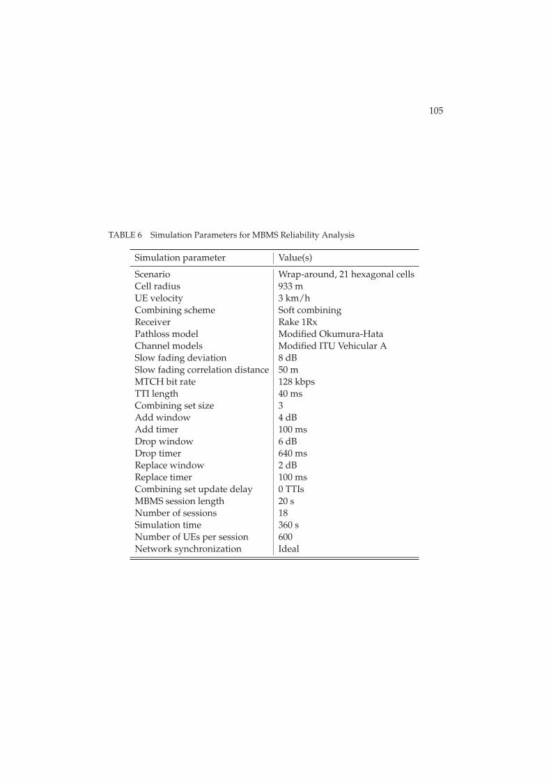
105
TABLE 6 Simulation Parameters for MBMS Reliability Analysis
Simulation parameter Value(s)
Scenario Wrap-around, 21 hexagonal cellsCell radius 933 mUE velocity 3 km/hCombining scheme Soft combiningReceiver Rake 1RxPathloss model Modified Okumura-HataChannel models Modified ITU Vehicular ASlow fading deviation 8 dBSlow fading correlation distance 50 mMTCH bit rate 128 kbpsTTI length 40 msCombining set size 3Add window 4 dBAdd timer 100 msDrop window 6 dBDrop timer 640 msReplace window 2 dBReplace timer 100 msCombining set update delay 0 TTIsMBMS session length 20 sNumber of sessions 18Simulation time 360 sNumber of UEs per session 600Network synchronization Ideal
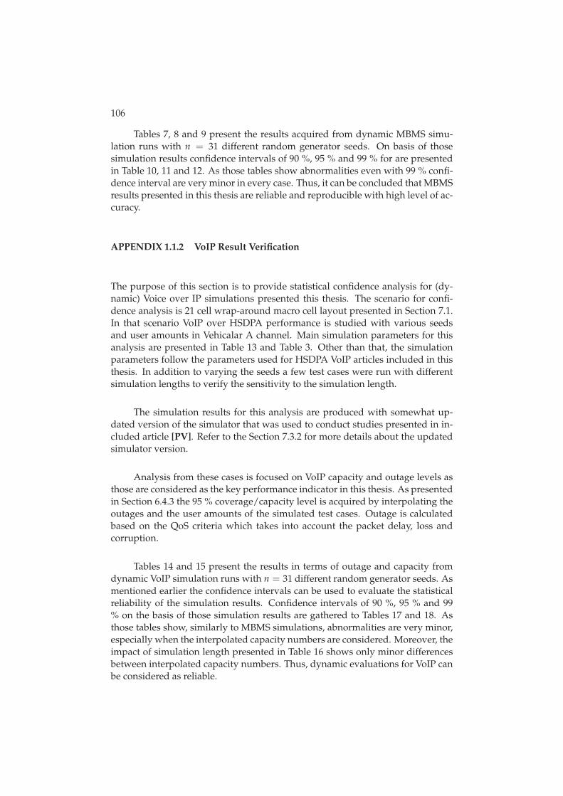
106
Tables 7, 8 and 9 present the results acquired from dynamic MBMS simu-lation runs with n = 31 different random generator seeds. On basis of thosesimulation results confidence intervals of 90 %, 95 % and 99 % for are presentedin Table 10, 11 and 12. As those tables show abnormalities even with 99 % confi-dence interval are very minor in every case. Thus, it can be concluded that MBMSresults presented in this thesis are reliable and reproducible with high level of ac-curacy.
APPENDIX 1.1.2 VoIP Result Verification
The purpose of this section is to provide statistical confidence analysis for (dy-namic) Voice over IP simulations presented this thesis. The scenario for confi-dence analysis is 21 cell wrap-around macro cell layout presented in Section 7.1.In that scenario VoIP over HSDPA performance is studied with various seedsand user amounts in Vehicalar A channel. Main simulation parameters for thisanalysis are presented in Table 13 and Table 3. Other than that, the simulationparameters follow the parameters used for HSDPA VoIP articles included in thisthesis. In addition to varying the seeds a few test cases were run with differentsimulation lengths to verify the sensitivity to the simulation length.
The simulation results for this analysis are produced with somewhat up-dated version of the simulator that was used to conduct studies presented in in-cluded article [PV]. Refer to the Section 7.3.2 for more details about the updatedsimulator version.
Analysis from these cases is focused on VoIP capacity and outage levels asthose are considered as the key performance indicator in this thesis. As presentedin Section 6.4.3 the 95 % coverage/capacity level is acquired by interpolating theoutages and the user amounts of the simulated test cases. Outage is calculatedbased on the QoS criteria which takes into account the packet delay, loss andcorruption.
Tables 14 and 15 present the results in terms of outage and capacity fromdynamic VoIP simulation runs with n = 31 different random generator seeds. Asmentioned earlier the confidence intervals can be used to evaluate the statisticalreliability of the simulation results. Confidence intervals of 90 %, 95 % and 99% on the basis of those simulation results are gathered to Tables 17 and 18. Asthose tables show, similarly to MBMS simulations, abnormalities are very minor,especially when the interpolated capacity numbers are considered. Moreover, theimpact of simulation length presented in Table 16 shows only minor differencesbetween interpolated capacity numbers. Thus, dynamic evaluations for VoIP canbe considered as reliable.

107
TABLE 7 Satisfied Users with Different Seed Values, BLER < 10 %
Ec/Ior -11 dB Ec/Ior -9 dB Ec/Ior -7 dB Ec/Ior -5 dB
0.9379 0.9989 1.0000 1.00000.9387 0.9991 1.0000 1.00000.9370 0.9989 1.0000 1.00000.9367 0.9992 1.0000 1.00000.9379 0.9987 1.0000 1.00000.9364 0.9989 1.0000 1.00000.9369 0.9988 1.0000 1.00000.9381 0.9990 1.0000 1.00000.9391 0.9988 1.0000 1.00000.9372 0.9989 1.0000 1.00000.9370 0.9988 1.0000 1.00000.9386 0.9989 1.0000 1.00000.9376 0.9988 1.0000 1.00000.9365 0.9990 1.0000 1.00000.9364 0.9989 1.0000 1.00000.9368 0.9990 1.0000 1.00000.9376 0.9990 1.0000 1.00000.9378 0.9988 1.0000 1.00000.9364 0.9989 1.0000 1.00000.9379 0.9988 1.0000 1.00000.9371 0.9991 1.0000 1.00000.9369 0.9989 1.0000 1.00000.9376 0.9986 1.0000 1.00000.9371 0.9989 1.0000 1.00000.9378 0.9988 1.0000 1.00000.9380 0.9990 1.0000 1.00000.9365 0.9990 1.0000 1.00000.9378 0.9988 1.0000 1.00000.9372 0.9991 1.0000 1.00000.9362 0.9990 1.0000 1.00000.9360 0.9990 1.0000 1.0000

108
TABLE 8 Satisfied Users with Different Seed Values, BLER < 1 %
Ec/Ior -11 dB Ec/Ior -9 dB Ec/Ior -7 dB Ec/Ior -5 dB
0.5526 0.8489 0.9797 0.99890.5510 0.8507 0.9815 0.99910.5516 0.8469 0.9796 0.99870.5513 0.8477 0.9783 0.99860.5526 0.8481 0.9797 0.99890.5519 0.8495 0.9816 0.99860.5538 0.8461 0.9797 0.99810.5518 0.8486 0.9800 0.99850.5507 0.8491 0.9807 0.99870.5529 0.8476 0.9794 0.99880.5518 0.8495 0.9813 0.99880.5538 0.8489 0.9813 0.99890.5496 0.8488 0.9806 0.99850.5512 0.8490 0.9805 0.99840.5519 0.8472 0.9797 0.99850.5507 0.8466 0.9817 0.99930.5504 0.8478 0.9795 0.99860.5523 0.8482 0.9794 0.99880.5518 0.8480 0.9797 0.99810.5530 0.8526 0.9804 0.99880.5501 0.8492 0.9791 0.99770.5522 0.8491 0.9799 0.99860.5497 0.8466 0.9796 0.99840.5503 0.8483 0.9796 0.99830.5531 0.8518 0.9804 0.99900.5552 0.8496 0.9811 0.99870.5529 0.8469 0.9802 0.99860.5528 0.8506 0.9807 0.99820.5493 0.8481 0.9800 0.99840.5525 0.8476 0.9797 0.99840.5501 0.8484 0.9806 0.9992
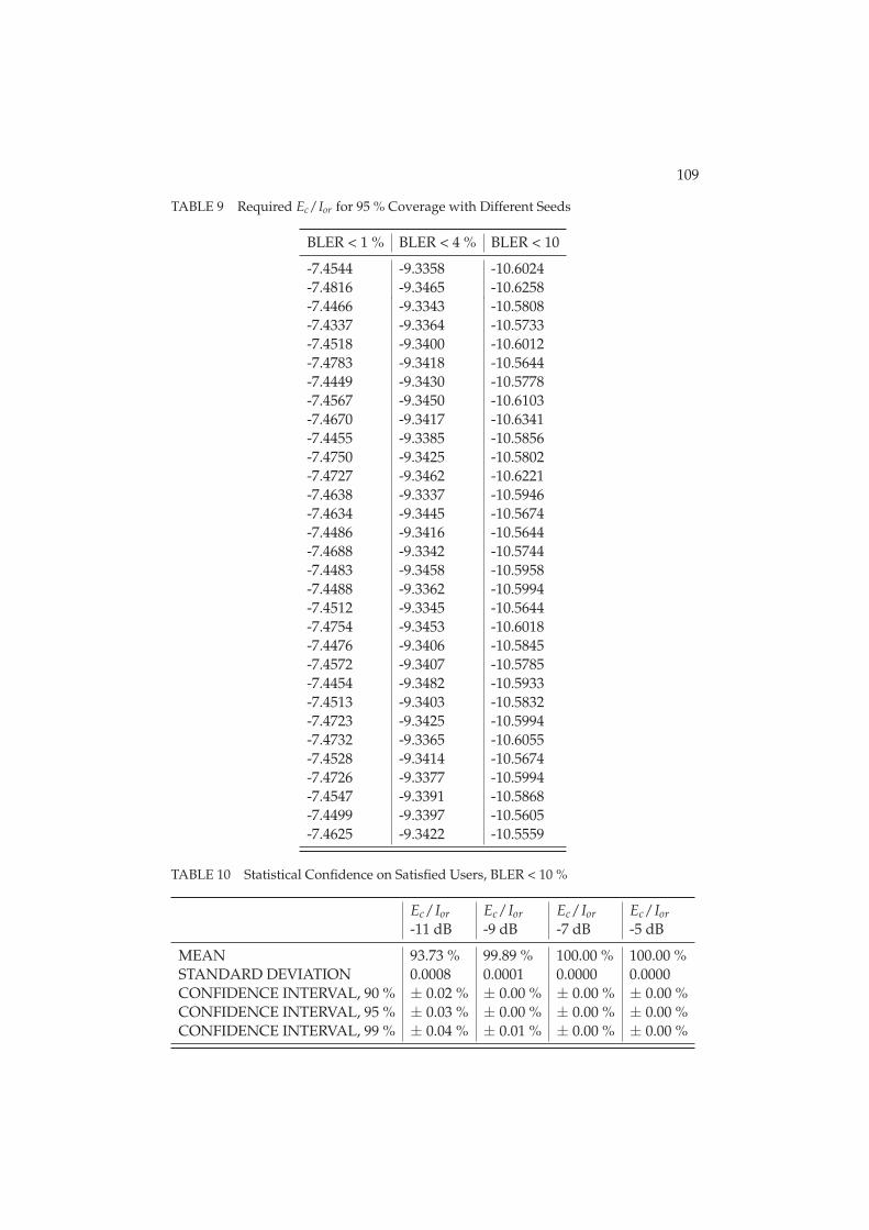
109
TABLE 9 Required Ec/Ior for 95 % Coverage with Different Seeds
BLER < 1 % BLER < 4 % BLER < 10
-7.4544 -9.3358 -10.6024-7.4816 -9.3465 -10.6258-7.4466 -9.3343 -10.5808-7.4337 -9.3364 -10.5733-7.4518 -9.3400 -10.6012-7.4783 -9.3418 -10.5644-7.4449 -9.3430 -10.5778-7.4567 -9.3450 -10.6103-7.4670 -9.3417 -10.6341-7.4455 -9.3385 -10.5856-7.4750 -9.3425 -10.5802-7.4727 -9.3462 -10.6221-7.4638 -9.3337 -10.5946-7.4634 -9.3445 -10.5674-7.4486 -9.3416 -10.5644-7.4688 -9.3342 -10.5744-7.4483 -9.3458 -10.5958-7.4488 -9.3362 -10.5994-7.4512 -9.3345 -10.5644-7.4754 -9.3453 -10.6018-7.4476 -9.3406 -10.5845-7.4572 -9.3407 -10.5785-7.4454 -9.3482 -10.5933-7.4513 -9.3403 -10.5832-7.4723 -9.3425 -10.5994-7.4732 -9.3365 -10.6055-7.4528 -9.3414 -10.5674-7.4726 -9.3377 -10.5994-7.4547 -9.3391 -10.5868-7.4499 -9.3397 -10.5605-7.4625 -9.3422 -10.5559
TABLE 10 Statistical Confidence on Satisfied Users, BLER < 10 %
Ec/Ior Ec/Ior Ec/Ior Ec/Ior-11 dB -9 dB -7 dB -5 dB
MEAN 93.73 % 99.89 % 100.00 % 100.00 %STANDARD DEVIATION 0.0008 0.0001 0.0000 0.0000CONFIDENCE INTERVAL, 90 % ± 0.02 % ± 0.00 % ± 0.00 % ± 0.00 %CONFIDENCE INTERVAL, 95 % ± 0.03 % ± 0.00 % ± 0.00 % ± 0.00 %CONFIDENCE INTERVAL, 99 % ± 0.04 % ± 0.01 % ± 0.00 % ± 0.00 %
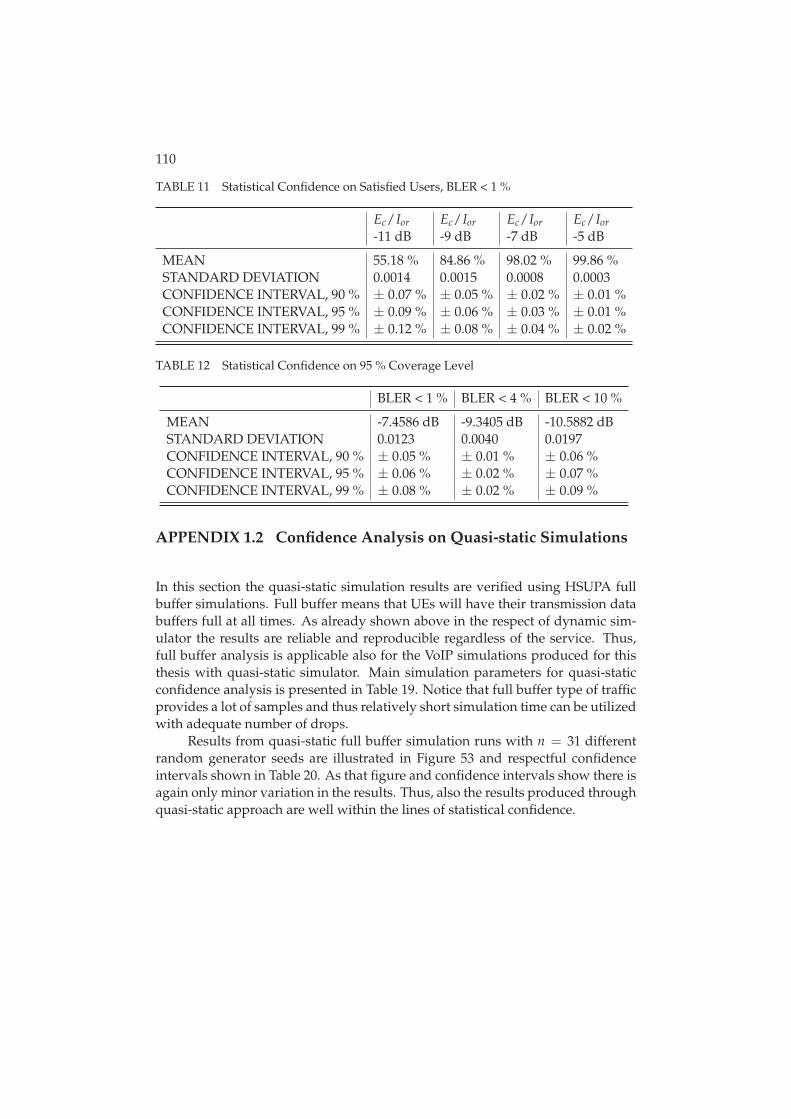
110
TABLE 11 Statistical Confidence on Satisfied Users, BLER < 1 %
Ec/Ior Ec/Ior Ec/Ior Ec/Ior-11 dB -9 dB -7 dB -5 dB
MEAN 55.18 % 84.86 % 98.02 % 99.86 %STANDARD DEVIATION 0.0014 0.0015 0.0008 0.0003CONFIDENCE INTERVAL, 90 % ± 0.07 % ± 0.05 % ± 0.02 % ± 0.01 %CONFIDENCE INTERVAL, 95 % ± 0.09 % ± 0.06 % ± 0.03 % ± 0.01 %CONFIDENCE INTERVAL, 99 % ± 0.12 % ± 0.08 % ± 0.04 % ± 0.02 %
TABLE 12 Statistical Confidence on 95 % Coverage Level
BLER < 1 % BLER < 4 % BLER < 10 %
MEAN -7.4586 dB -9.3405 dB -10.5882 dBSTANDARD DEVIATION 0.0123 0.0040 0.0197CONFIDENCE INTERVAL, 90 % ± 0.05 % ± 0.01 % ± 0.06 %CONFIDENCE INTERVAL, 95 % ± 0.06 % ± 0.02 % ± 0.07 %CONFIDENCE INTERVAL, 99 % ± 0.08 % ± 0.02 % ± 0.09 %
APPENDIX 1.2 Confidence Analysis on Quasi-static Simulations
In this section the quasi-static simulation results are verified using HSUPA fullbuffer simulations. Full buffer means that UEs will have their transmission databuffers full at all times. As already shown above in the respect of dynamic sim-ulator the results are reliable and reproducible regardless of the service. Thus,full buffer analysis is applicable also for the VoIP simulations produced for thisthesis with quasi-static simulator. Main simulation parameters for quasi-staticconfidence analysis is presented in Table 19. Notice that full buffer type of trafficprovides a lot of samples and thus relatively short simulation time can be utilizedwith adequate number of drops.
Results from quasi-static full buffer simulation runs with n = 31 differentrandom generator seeds are illustrated in Figure 53 and respectful confidenceintervals shown in Table 20. As that figure and confidence intervals show there isagain only minor variation in the results. Thus, also the results produced throughquasi-static approach are well within the lines of statistical confidence.
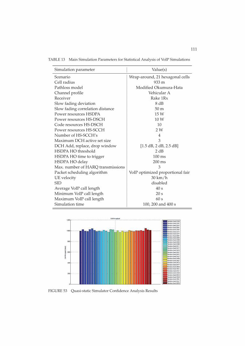
111
TABLE 13 Main Simulation Parameters for Statistical Analysis of VoIP Simulations
Simulation parameter Value(s)
Scenario Wrap-around, 21 hexagonal cellsCell radius 933 mPathloss model Modified Okumura-HataChannel profile Vehicular AReceiver Rake 1RxSlow fading deviation 8 dBSlow fading correlation distance 50 mPower resources HSDPA 15 WPower resources HS-DSCH 10 WCode resources HS-DSCH 10Power resources HS-SCCH 2 WNumber of HS-SCCH’s 4Maximum DCH active set size 3DCH Add, replace, drop window [1.5 dB, 2 dB, 2.5 dB]HSDPA HO threshold 2 dBHSDPA HO time to trigger 100 msHSDPA HO delay 200 msMax. number of HARQ transmissions 3Packet scheduling algorithm VoIP optimized proportional fairUE velocity 30 km/hSID disabledAverage VoIP call length 40 sMinimum VoIP call length 20 sMaximum VoIP call length 60 sSimulation time 100, 200 and 400 s
FIGURE 53 Quasi-static Simulator Confidence Analysis Results
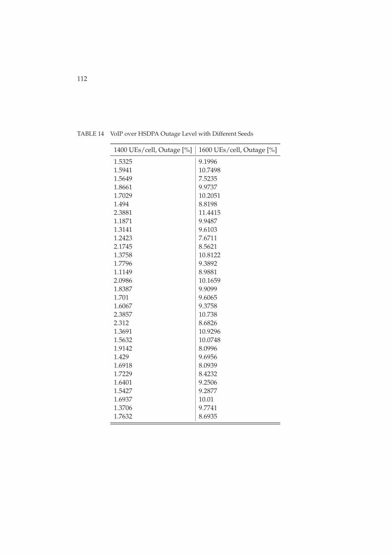
112
TABLE 14 VoIP over HSDPA Outage Level with Different Seeds
1400 UEs/cell, Outage [%] 1600 UEs/cell, Outage [%]
1.5325 9.19961.5941 10.74981.5649 7.52351.8661 9.97371.7029 10.20511.494 8.81982.3881 11.44151.1871 9.94871.3141 9.61031.2423 7.67112.1745 8.56211.3758 10.81221.7796 9.38921.1149 8.98812.0986 10.16591.8387 9.90991.701 9.60651.6067 9.37582.3857 10.7382.312 8.68261.3691 10.92961.5632 10.07481.9142 8.09961.429 9.69561.6918 8.09391.7229 8.42321.6401 9.25061.5427 9.28771.6937 10.011.3706 9.77411.7632 8.6935
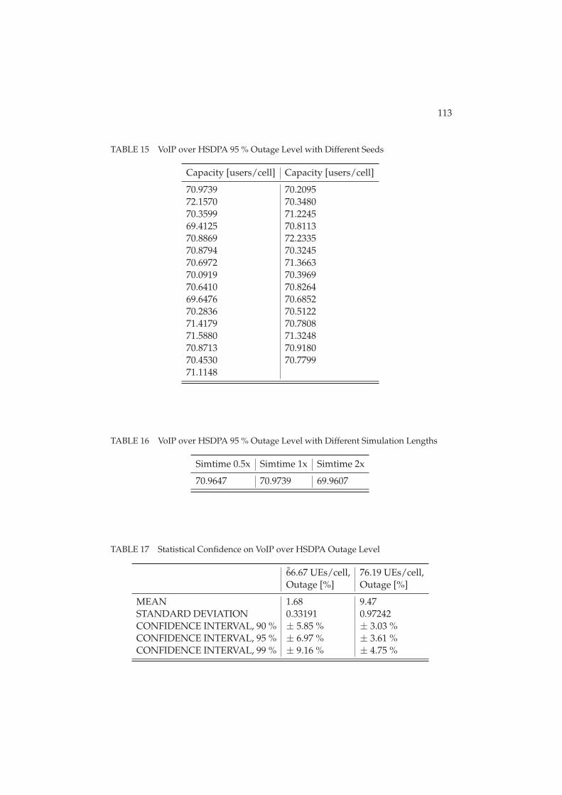
113
TABLE 15 VoIP over HSDPA 95 % Outage Level with Different Seeds
Capacity [users/cell] Capacity [users/cell]
70.9739 70.209572.1570 70.348070.3599 71.224569.4125 70.811370.8869 72.233570.8794 70.324570.6972 71.366370.0919 70.396970.6410 70.826469.6476 70.685270.2836 70.512271.4179 70.780871.5880 71.324870.8713 70.918070.4530 70.779971.1148
TABLE 16 VoIP over HSDPA 95 % Outage Level with Different Simulation Lengths
Simtime 0.5x Simtime 1x Simtime 2x
70.9647 70.9739 69.9607
TABLE 17 Statistical Confidence on VoIP over HSDPA Outage Level
6̃6.67 UEs/cell, 76.19 UEs/cell,Outage [%] Outage [%]
MEAN 1.68 9.47STANDARD DEVIATION 0.33191 0.97242CONFIDENCE INTERVAL, 90 % ± 5.85 % ± 3.03 %CONFIDENCE INTERVAL, 95 % ± 6.97 % ± 3.61 %CONFIDENCE INTERVAL, 99 % ± 9.16 % ± 4.75 %
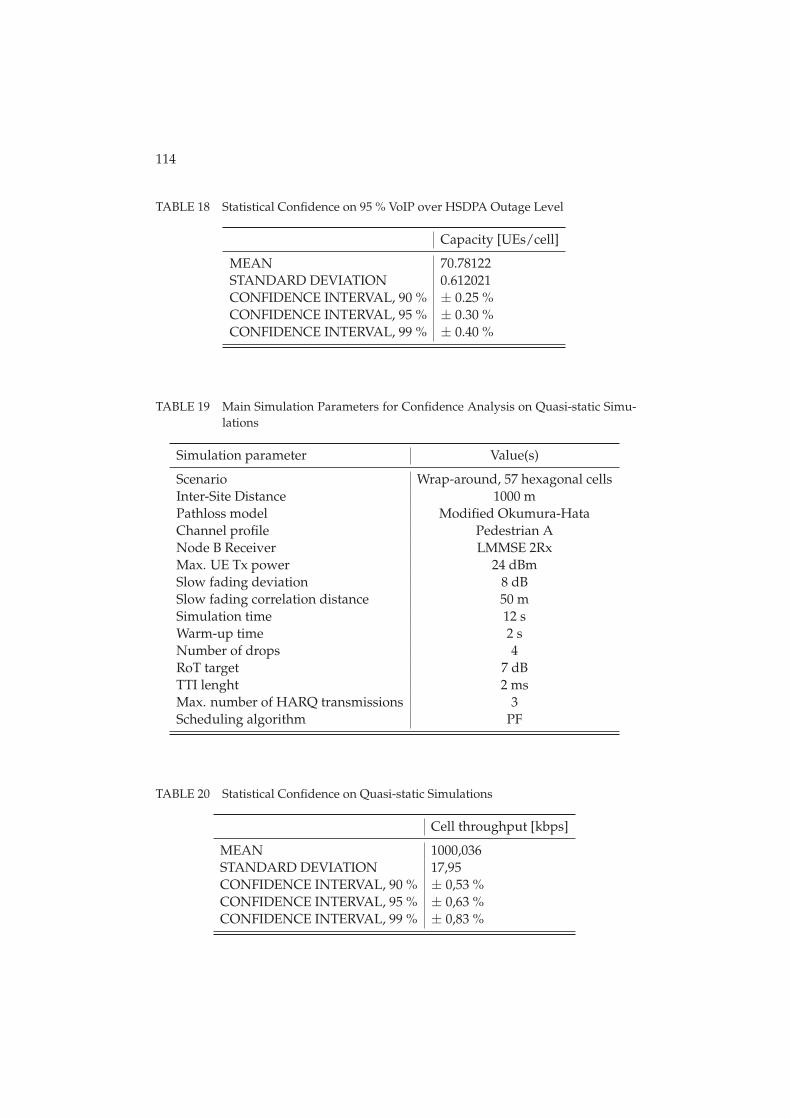
114
TABLE 18 Statistical Confidence on 95 % VoIP over HSDPA Outage Level
Capacity [UEs/cell]
MEAN 70.78122STANDARD DEVIATION 0.612021CONFIDENCE INTERVAL, 90 % ± 0.25 %CONFIDENCE INTERVAL, 95 % ± 0.30 %CONFIDENCE INTERVAL, 99 % ± 0.40 %
TABLE 19 Main Simulation Parameters for Confidence Analysis on Quasi-static Simu-lations
Simulation parameter Value(s)
Scenario Wrap-around, 57 hexagonal cellsInter-Site Distance 1000 mPathloss model Modified Okumura-HataChannel profile Pedestrian ANode B Receiver LMMSE 2RxMax. UE Tx power 24 dBmSlow fading deviation 8 dBSlow fading correlation distance 50 mSimulation time 12 sWarm-up time 2 sNumber of drops 4RoT target 7 dBTTI lenght 2 msMax. number of HARQ transmissions 3Scheduling algorithm PF
TABLE 20 Statistical Confidence on Quasi-static Simulations
Cell throughput [kbps]
MEAN 1000,036STANDARD DEVIATION 17,95CONFIDENCE INTERVAL, 90 % ± 0,53 %CONFIDENCE INTERVAL, 95 % ± 0,63 %CONFIDENCE INTERVAL, 99 % ± 0,83 %
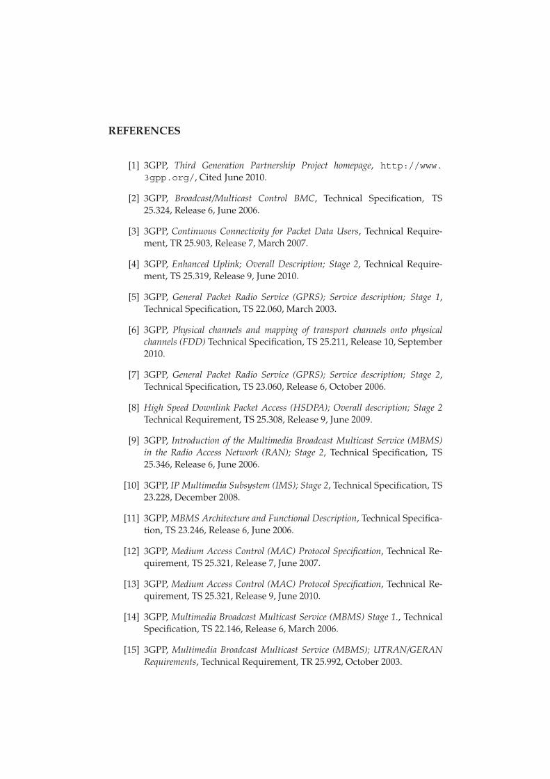
REFERENCES
[1] 3GPP, Third Generation Partnership Project homepage, http://www.3gpp.org/, Cited June 2010.
[2] 3GPP, Broadcast/Multicast Control BMC, Technical Specification, TS25.324, Release 6, June 2006.
[3] 3GPP, Continuous Connectivity for Packet Data Users, Technical Require-ment, TR 25.903, Release 7, March 2007.
[4] 3GPP, Enhanced Uplink; Overall Description; Stage 2, Technical Require-ment, TS 25.319, Release 9, June 2010.
[5] 3GPP, General Packet Radio Service (GPRS); Service description; Stage 1,Technical Specification, TS 22.060, March 2003.
[6] 3GPP, Physical channels and mapping of transport channels onto physicalchannels (FDD) Technical Specification, TS 25.211, Release 10, September2010.
[7] 3GPP, General Packet Radio Service (GPRS); Service description; Stage 2,Technical Specification, TS 23.060, Release 6, October 2006.
[8] High Speed Downlink Packet Access (HSDPA); Overall description; Stage 2Technical Requirement, TS 25.308, Release 9, June 2009.
[9] 3GPP, Introduction of the Multimedia Broadcast Multicast Service (MBMS)in the Radio Access Network (RAN); Stage 2, Technical Specification, TS25.346, Release 6, June 2006.
[10] 3GPP, IP Multimedia Subsystem (IMS); Stage 2, Technical Specification, TS23.228, December 2008.
[11] 3GPP, MBMS Architecture and Functional Description, Technical Specifica-tion, TS 23.246, Release 6, June 2006.
[12] 3GPP, Medium Access Control (MAC) Protocol Specification, Technical Re-quirement, TS 25.321, Release 7, June 2007.
[13] 3GPP, Medium Access Control (MAC) Protocol Specification, Technical Re-quirement, TS 25.321, Release 9, June 2010.
[14] 3GPP, Multimedia Broadcast Multicast Service (MBMS) Stage 1., TechnicalSpecification, TS 22.146, Release 6, March 2006.
[15] 3GPP, Multimedia Broadcast Multicast Service (MBMS); UTRAN/GERANRequirements, Technical Requirement, TR 25.992, October 2003.
116
[16] 3GPP, Physical Layer; Measurements (FDD), Technical Requirement, TS25.215, Release 9, March 2010.
[17] 3GPP, Physical Layer Procedures (FDD), Technical Requirement, TS 25.214,Release 7, March 2007.
[18] 3GPP, Physical Layer Procedures (FDD), Technical Requirement, TS 25.214,Release 9, March 2010.
[19] 3GPP, Radio Resource Control (RRC); Protocol Specification, Technical Re-quirement, TS 25.331, Release 9, June 2010.
[20] 3GPP, Requirements for Evolved UTRA (E-UTRA) and Evolved UTRAN (E-UTRAN), Technical Requirement, TR 25.913, Release 7, March 2006.
[21] 3GPP, Selection Procedures for the Choice of Radio Transmission Technologiesof the UMTS Technical Requirement, TR 101 112 (UMTS 30.03), April1998.
[22] 3GPP, Speech Codec Speech Processing Functions; Adaptive Multi-Rate -Wideband (AMR-WB) Speech Codec; General Description, Technical Speci-fication, TS 26.171, December 2008.
[23] 3GPP, Technical Realization of Cell Broadcast Service (CBS), Technical Spec-ification, TS 23.041, Release 6, January 2004.
[24] 3GPP, UTRAN Iub interface Node B Application Part (NBAP) Signalling,Technical Requirement, TS 25.433, Release 9, June 2010.
[25] A. Alexiou, C. Bouras, V. Kokkinos, and E. Rekkas, Power Efficient RadioBearer Selection in MBMS Multicast Mode, In Proceedings of ACM Inter-national Symposium on Modeling, Analysis and Simulation of Wirelessand Mobile Systems, Chania, Crete Island, Greece, October 2007.
[26] D. M. de Andrade, A. Klein, H. Holma, I. Viering, and G. Liebl, Perfor-mance Evaluation on Dual-Cell HSDPA Operation, In Proceedings of IEEE70th Vehicular Technology Conference Fall (VTC’09-Fall), Anchorage,Alaska, USA, September 2009.
[27] M. Bertinelli, and J. Jaatinen, VoIP over HSUPA: link level performancestudy, In Proceedings of 3rd International Symposium on Wireless Com-munication Systems (ISWCS’06), Valencia, Spain, September 2006.
[28] E. Biglieri, J. Proakis, and S. Shamai, Fading Channels; Information-theoreticand Communications Aspects, IEEE Transactions on Information Theory,October 1998.
[29] G. Boudreau et.al., Interference Coordination and Cancellation for 4G Net-works, IEEE Communications Magazine, vol. 47, pp. 74-81, April 2009.
117
[30] A. R. Braga, E. B. Rodrigues, and F. R. P. Cavalcanti, Packet schedulingfor VoIP over HSDPA in mixed traffic scenarios In Proceedings of 17th IEEEInternational Symposium on Personal, Indoor and Mobile Radio Com-munications (PIMRC’06), Helsinki, Finland, September 2006.
[31] T. Chen, M. Kuusela, and E. Malkamäki, Uplink Capacity of VoIP onHSUPA, In Proceedings of IEEE 63rd Vehicular Technology Conference,Melbourne, Australia, May 2006.
[32] M. Chuah, T. Hu, and W. Luo, UMTS Release 99/4 Airlink Enhancement forSupporting MBMS Services, In Proceedings of IEEE International Confer-ence on Communications, Paris, France, June 2004.
[33] Cisco, Echo Analysis for Voice over IP, http://www.cisco.com/en/US/docs/ios/solutions_docs/voip_solutions/EA_ISD.pdf,November 2002, Cited July 2010.
[34] A. Correia, J. Silva, N. Souto, L. Silva, A. Boal, and A. Soares, Multi-Resolution Broadcast/Multicast Systems for MBMS, IEEE Transactions onBroadcasting, vol 53, no. 1, March 2007.
[35] E. Dahlman, S. Parkvall, J. Sköld, and P. Beming, 3G Evolution - HSPA andLTE for Mobile Broadband, 1st edition, Elsevier Ltd., 2007.
[36] E. Damosso, and L. M. Correia (editors), Digital Mobile Radio Towards Fu-ture Generation Systems, Technical report, COST 231 Final report, 1999.
[37] J. Eberspächer, H.-J. Vögel, C. Bettstetter, and C. Hartmann, GSM - Archi-tecture, Protocols and Services, 3rd edition, John Wiley & Sons Ltd, 2009.
[38] Ericsson, Introduction to IMS, http://www.ericsson.com/technology/whitepapers/8123_Intro_to_ims_a.pdf, Er-icsson white paper, March 2007, Cited December 2009.
[39] O. Fresan, C. Tao, E. Malkamaki, and T. Ristaniemi, DPCCH gating gainfor Voice over IP on HSUPA, in Proceedings of IEEE Wireless Communi-cations and Networking Conference (WCNC’07), China, March 2007.
[40] O. Fresan, C. Tao, K. Ranta-aho, and T. Ristaniemi, Dynamic PacketBundling for VoIP Transmission Over Rel’7 HSUPA with 10ms TTI Length,In Proceedings of 4th International Symposium on Wireless Communi-cation Systems (ISWCS’07), Trondheim, Norway, October 2007.
[41] L. Harte, and D. Bowler, Introduction to Mobile Telephone Systems-1G, 2G,2.5G, and 3G Wireless Technologies and Services 2nd edition, Althos Pub-lishing, 2003.
[42] F. Hartung, U. Horn, J. Huschke, M. Kampmann, T. Lohmar, and M. Lun-devall, Delivery of Broadcast Services in 3G Networks, IEEE Transactions onBroadcasting, vol. 53, no. 1, March 2007.
118
[43] M. Hata, Empirical Formula for Propagation Loss in Land mobile Radio Ser-vices IEEE Transactions on Vehicular Technology, August 1980.
[44] H. Holma, M. Kuusela, E. Malkamäki, K. Ranta-aho, and T. Chen, VoIPover HSPA with 3GPP release 7, In Proceedings of IEEE InternationalSymposium on Personal, Indoor and Mobile Radio Communications(PIMRC), Helsinki, Finland, September 2006.
[45] H. Holma, and A. Toskala, WCDMA for UMTS: Radio Access for ThirdGeneration Mobile Communications, 4th edition, John Wiley & Sons Ltd,2007.
[46] H. Holma, and A. Toskala, HSDPA/HSUPA for UMTS, 1st edition, JohnWiley & Sons Ltd, 2006.
[47] A. Hottinen, O. Tirkkonen, and R. Wichman, Multi-Antenna TransceiverTechniques for 3G and Beyond, John Wiley & Sons Ltd, 2003.
[48] A. Hottinen, O. Tirkkonen, and R. Wichman, Multi-Antenna TransceiverTechniques for 3G and Beyond, John Wiley & Sons, Ltd, 2003.
[49] S. Hämäläinen, WCDMA Radio Network Performance, Doctoral thesis,University of Jyväskylä, 2003.
[50] S. Hämäläinen, H. Holma, and K. Sipilä, Advanced WCDMA Radio Net-work Simulator, In Proceedings of IEEE International Symposium onPersonal, Indoor and Mobile Radio Communications (PIMRC), Osaka,Japan, September 1999.
[51] S. Hämäläinen, P. Slanina, M. Hartman, A. Leppeteläinen, H. Holma,and O. Salonaho A Novel Interface Between Link and System Simulations, InProceedings of ACTS Summit, Aalborg, Denmark, October 1997.
[52] IETF, SIP: Session Initiation Protocol, RFC 3261, June 2002.
[53] IETF, SDP: Session Description Protocol, RFC 2327, April 1998.
[54] IETF, RTP: A Transport Protocol for Real-Time Applications, RFC 3550, July2003.
[55] IETF, RTP Payload Format for MPEG1/MPEG2 Video, RFC 2250, January1998.
[56] IETF, RTP Payload Format for MPEG-4 Audio/Visual Streams, RFC 3016,November 2000.
[57] IETF, RTP Payload for Text Conversation, RFC 4103, June 2005.
[58] IETF, Compressing IP/UDP/RTP Headers for Low-Speed Serial Links, RFC2508, February 1999.
119
[59] IETF, RObust Header Compression (ROHC): Framework and Four Profiles:RTP, UDP, ESP, and Uncompressed, RFC 3095, July 2001.
[60] ITU-R, Guidelines for Evaluation of Radio Transmission Technologies for IMT-2000 Recommendation, ITU-R M.1225, 1997.
[61] ITU-T, Series G: Transmission Systems and Media, Digital Systems and Net-works: International Telephone Connections and circuits - General Recommen-dations on the transmission quality for an entire international telephone con-nection, Recommendation G.114, May 2003.
[62] K. Johansson, J. Bergman, D. Gerstenberger, M. Blomgren, and A.Wallen, Multi-Carrier HSPA Evolution In Proceedings of IEEE 69th Ve-hicular Technology Conference (VTC’09-Spring), Barcelona, Spain, April2009.
[63] J. Kurjenniemi, A Study of TD-CDMA and WCDMA Radio Network En-hancements, Doctoral thesis, University of Jyväskylä, 2005.
[64] S. Li, F.-C. Cheng, L. Song, and N. Ansari, Network Coordination and In-terference Mitigation for HSDPA and EV-DO Forward Link, In Proceedingsof IEEE Global Telecommunications Conference (GLOBECOM’06), SanFrancisco, California, USA, November 2006.
[65] M. Luby, T. Gasiba, T. Stockhammer, and M. Watson, Reliable MultimediaDownload Delivery in Cellular Broadcast Networks, IEEE Transactions onBroadcasting, vol 53, no. 1, March 2007.
[66] P. Lunden, and M. Kuusela, Enhancing Performance of VoIP over HSDPA,In Proceedings of 65th IEEE Vehicular Technology Conference, Dublin,Ireland, April 2007.
[67] M. C. Necker, Interference Coordination in Cellular OFDMA Networks, IEEENetworks, vol. 22, pp. 12-19, November-December 2008.
[68] J. Niemelä, J. Borkowski, and J. Lempiäinen, Performance of StaticWCDMA Simulator In Proceedings of 8th IEEE International Sympo-sium on Wireless Personal Multimedia Communications (WPMC’05),Aalborg, Denmark, September 2005.
[69] T. Nihtilä, Performance of Advanced Transmission and Reception Algorithmsfor High Speed Downlink Packet Access, Doctoral thesis, ISBN 978-951-39-3236-7, University of Jyväskylä, 2008.
[70] Y. Okumura, E. Ohmori, T. Kawano, and K. Fukuda, Field Strength and ItsVariability in VHF and UHF Land-mobile Service, Review of the ElectricalCommunication Laboratory, 1968.
[71] R. Price, and P. E. Green Jr., A Communication Technique for MultipathChannels, In Proceedings of the IRE, pages 555 - 570, March 1958.
120
[72] J. G. Proakism, Digital Communications, McGraw-Hill, 1995.
[73] F. Rui, F. Persson, M. Nordberg, S. Wanstedt, M. Qingyu, and G. Xinyu,Coverage Study for VoIP over Enhanced Uplink, In Proceedings of IEEE 63rdVehicular Technology Conference, Melbourne, Australia, May 2006.
[74] S. Sambhwani, W. Zhang, and W. Zeng, Uplink Interference Cancella-tion in HSPA: Principles and Practice, http://www.qualcomm.com/documents/, Qualcom white paper, January 2009, cited August 2010.
[75] J. S. Seybold, Introduction to RF Propagation, John Wiley & Sons, Ltd, 2005.
[76] A. Simonsson, Frequency Reuse and Intercell Interference Co-ordination in E-UTRAN, In proceedings of IEEE 65th Vehicular Technology Conference(VTC’07-Spring), April 2007.
[77] A. Soares, A. Correia, J. Silva, and N. Souto, UE Counting Mechanism forMBMS Considering PtM Macro Diversity Combining Support in UMTS Net-works, In Proceedings of IEEE 9th International Symposium on SpreadSpectrum Techniques and Applications, August 2006.
[78] S. M. Sussman, A Matched Filter Communication System for MultipathChannels, IEEE Transactions on Information Theory, pages: 367 - 373,June 1960.
[79] G. L. Turin, Introduction to Spread-spectrum Antimultipath Techniques andTheir Applications to Urban Digital Radio, In Proceedings of the IEEE,March 1980.
[80] A. J. Viterbi, CDMA: Principles of Spread Spectrum Communication,Addison-Wesley Wireless Communications Series, 1995.
[81] S. Wager, and K. Sandlund, Performance Evaluation of HSDPA Mobility forVoice over IP, In Proceedings of 65th IEEE Vehicular Technology Confer-ence, Dublin, Ireland, April 2007.
[82] B. Wang, K. I. Pedersen, T. E. Kolding, and P. E. Mogensen, Performance ofVoIP on HSDPA, In Proceedings of 61st IEEE Vehicular Technology Con-ference, Stockholm, Sweden, May 2005.
[83] J. Wigard, M. Boussif, N. H. Madsen, M. Brix, S. Corneliussen, and E.A. Laursen, High Speed Uplink Packet Access Evaluation by Dynamic Net-work Simulations, In Proceedings of IEEE International Symposium onPersonal, Indoor and Mobile Radio Communications (PIMRC), Helsinki,Finland, September 2006.
[84] Wireless Intelligence, https://www.wirelessintelligence.com/, cited August2010.
121
[85] Y. Xiang, J. Luo, and C. Hartmann, Inter-cell Interference MitigationThrough Flexible Resource Reuse in OFDMA Based Communication Networks,In Proceedings of European Wireless 2007 (EW 2007), Paris, France, April2007.
[86] S.-R. Yang, and Y.-B. Lin, Modeling UMTS discontinuous reception mech-anism, IEEE Transactions on Wireless Communications, vol. 4, January2005.
[87] M. Zhang, T. Chen, and J. Hu, Throughput-based and Power-based LoadControl in HSUPA, Proceedings of International Conference on Wire-less Communications, Networking and Mobile Computing (WCNM),Wuhan, China, September 2005.
J Y V Ä S K Y L Ä S T U D I E S I N C O M P U T I N G
1 ROPPONEN, JANNE, Software risk management -foundations, principles and empiricalfindings. 273 p. Yhteenveto 1 p. 1999.
2 KUZMIN, DMITRI, Numerical simulation ofreactive bubbly flows. 110 p. Yhteenveto 1 p.1999.
3 KARSTEN, HELENA, Weaving tapestry:collaborative information technology andorganisational change. 266 p. Yhteenveto3 p. 2000.
4 KOSKINEN, JUSSI, Automated transienthypertext support for software maintenance.98 p. (250 p.) Yhteenveto 1 p. 2000.
5 RISTANIEMI, TAPANI, Synchronization and blindsignal processing in CDMA systems. -Synkronointi ja sokea signaalinkäsittelyCDMA järjestelmässä. 112 p. Yhteenveto 1 p.2000.
6 LAITINEN, MIKA, Mathematical modelling ofconductive-radiative heat transfer. 20 p.(108 p.) Yhteenveto 1 p. 2000.
7 KOSKINEN, MINNA, Process metamodelling.Conceptual foundations and application. 213p. Yhteenveto 1 p. 2000.
8 SMOLIANSKI, ANTON, Numerical modeling oftwo-fluid interfacial flows. 109 p. Yhteenveto1 p. 2001.
9 NAHAR, NAZMUN, Information technologysupported technology transfer process. Amulti-site case study of high-tech enterprises.377 p. Yhteenveto 3 p. 2001.
10 FOMIN, VLADISLAV V., The process of standardmaking. The case of cellular mobile telephony.- Standardin kehittämisen prosessi. Tapaus-tutkimus solukkoverkkoon perustuvastamatkapuhelintekniikasta. 107 p. (208 p.)Yhteenveto 1 p. 2001.
11 PÄIVÄRINTA, TERO, A genre-based approachto developing electronic documentmanagement in the organization. 190 p.Yhteenveto 1 p. 2001.
12 HÄKKINEN, ERKKI, Design, implementation andevaluation of neural data analysisenvironment. 229 p. Yhteenveto 1 p. 2001.
13 HIRVONEN, KULLERVO, Towards betteremployment using adaptive control of labourcosts of an enterprise. 118 p. Yhteenveto 4 p.2001.
14 MAJAVA, KIRSI, Optimization-based techniquesfor image restoration. 27 p. (142 p.)Yhteenveto 1 p. 2001.
15 SAARINEN, KARI, Near infra-red measurementbased control system for thermo-mechanicalrefiners. 84 p. (186 p.) Yhteenveto 1 p. 2001.
16 FORSELL, MARKO, Improving component reusein software development. 169 p. Yhteenveto1 p. 2002.
17 VIRTANEN, PAULI, Neuro-fuzzy expert systemsin financial and control engineering.245 p. Yhteenveto 1 p. 2002.
18 KOVALAINEN, MIKKO, Computer mediatedorganizational memory for process control.
Moving CSCW research from an idea to aproduct. 57 p. (146 p.) Yhteenveto 4 p. 2002.
19 HÄMÄLÄINEN, TIMO, Broadband networkquality of service and pricing. 140 p.Yhteenveto 1 p. 2002.
20 MARTIKAINEN, JANNE, Efficient solvers fordiscretized elliptic vector-valued problems.25 p. (109 p.) Yhteenveto 1 p. 2002.
21 MURSU, ANJA, Information systemsdevelopment in developing countries. Riskmanagement and sustainability analysis inNigerian software companies. 296 p. Yhteen-veto 3 p. 2002.
22 SELEZNYOV, ALEXANDR, An anomaly intrusiondetection system based on intelligent userrecognition. 186 p. Yhteenveto 3 p. 2002.
23 LENSU, ANSSI, Computationally intelligentmethods for qualitative data analysis. 57 p.(180 p.) Yhteenveto 1 p. 2002.
24 RYABOV, VLADIMIR, Handling imperfecttemporal relations. 75 p. (145 p.) Yhteenveto2 p. 2002.
25 TSYMBAL, ALEXEY, Dynamic integration of datamining methods in knowledge discoverysystems. 69 p. (170 p.) Yhteenveto 2 p. 2002.
26 AKIMOV, VLADIMIR, Domain decompositionmethods for the problems with boundarylayers. 30 p. (84 p.). Yhteenveto 1 p. 2002.
27 SEYUKOVA-RIVKIND, LUDMILA, Mathematical andnumerical analysis of boundary valueproblems for fluid flow. 30 p. (126 p.) Yhteen-veto 1 p. 2002.
28 HÄMÄLÄINEN, SEPPO, WCDMA Radio networkperformance. 235 p. Yhteenveto 2 p. 2003.
29 PEKKOLA, SAMULI, Multiple media in groupwork. Emphasising individual users indistributed and real-time CSCW systems.210 p. Yhteenveto 2 p. 2003.
30 MARKKULA, JOUNI, Geographic personal data,its privacy protection and prospects in alocation-based service environment. 109 p.Yhteenveto 2 p. 2003.
31 HONKARANTA, ANNE, From genres to contentanalysis. Experiences from four caseorganizations. 90 p. (154 p.) Yhteenveto 1 p.2003.
32 RAITAMÄKI, JOUNI, An approach to linguisticpattern recognition using fuzzy systems.169 p. Yhteenveto 1 p. 2003.
33 SAALASTI, SAMI, Neural networks for heart ratetime series analysis. 192 p. Yhteenveto 5 p.2003.
34 NIEMELÄ, MARKETTA, Visual search ingraphical interfaces: a user psychologicalapproach. 61 p. (148 p.) Yhteenveto 1 p. 2003.
35 YOU, YU, Situation Awareness on the worldwide web. 171 p. Yhteenveto 2 p. 2004.
36 TAATILA, VESA, The concept of organizationalcompetence – A foundational analysis.- Perusteanalyysi organisaationkompetenssin käsitteestä. 111 p. Yhteenveto 2p. 2004.
J Y V Ä S K Y L Ä S T U D I E S I N C O M P U T I N G
37 LYYTIKÄINEN, VIRPI, Contextual and structuralmetadata in enterprise documentmanagement. - Konteksti- ja rakennemetatietoorganisaation dokumenttien hallinnassa.73 p. (143 p.) Yhteenveto 1 p. 2004.
38 KAARIO, KIMMO, Resource allocation and loadbalancing mechanisms for providing qualityof service in the Internet. 171 p. Yhteenveto1 p. 2004.
39 ZHANG, ZHEYING, Model component reuse.Conceptual foundations and application inthe metamodeling-based systems analysisand design environment. 76 p. (214 p.) Yh-teenveto 1 p. 2004.
40 HAARALA, MARJO, Large-scale nonsmoothoptimization variable metric bundle methodwith limited memory. 107 p. Yhteenveto 1 p.2004.
41 KALVINE, VIKTOR, Scattering and point spectrafor elliptic systems in domains withcylindrical ends. 82 p. 2004.
42 DEMENTIEVA, MARIA, Regularization inmultistage cooperative games. 78 p. 2004.
43 MAARANEN, HEIKKI, On heuristic hybridmethods and structured point sets in globalcontinuous optimization. 42 p. (168 p.)Yhteenveto 1 p. 2004.
44 FROLOV, MAXIM, Reliable control overapproximation errors by functional type aposteriori estimates. 39 p. (112 p.) 2004.
45 ZHANG, JIAN, Qos- and revenue-aware resourceallocation mechanisms in multiclass IPnetworks. 85 p. (224 p.) 2004.
46 KUJALA, JANNE, On computation in statisticalmodels with a psychophysical application. 40p. (104 p.) 2004.,
47 SOLBAKOV, VIATCHESLAV, Application ofmathematical modeling for waterenvironment problems. 66 p. (118 p.) 2004.
48 HIRVONEN, ARI P., Enterprise architectureplanning in practice. The Perspectives ofinformation and communication technologyservice provider and end-user. 44 p. (135 p.)Yhteenveto 2 p. 2005.
49 VARTIAINEN, TERO, Moral conflicts in a projectcourse in information systems education.320 p. Yhteenveto 1p. 2005.
50 HUOTARI, JOUNI, Integrating graphicalinformation system models with visualizationtechniques. - Graafisten tietojärjestelmäku-vausten integrointi visualisointitekniikoilla.56 p. (157 p.) Yhteenveto 1p. 2005.
51 WALLENIUS, EERO R., Control and managementof multi-access wireless networks. 91 p.(192 p.) Yhteenveto 3 p. 2005.
52 LEPPÄNEN, MAURI, An ontological frameworkand a methodical skeleton for methodengineering – A contextual approach. 702 p.Yhteenveto 2 p. 2005.
53 MATYUKEVICH, SERGEY, The nonstationaryMaxwell system in domains with edges andconical points. 131 p. Yhteenveto 1 p. 2005.
54 SAYENKO, ALEXANDER, Adaptive scheduling forthe QoS supported networks. 120 p. (217 p.)2005.
55 KURJENNIEMI, JANNE, A study of TD-CDMA andWCDMA radio network enhancements. 144 p.(230 p.) Yhteenveto 1 p. 2005.
56 PECHENIZKIY, MYKOLA, Feature extraction forsupervised learning in knowledge discoverysystems. 86 p. (174 p.) Yhteenveto 2 p. 2005.
57 IKONEN, SAMULI, Efficient numerical methodsfor pricing American options. 43 p. (155 p.)Yhteenveto 1 p. 2005.
58 KÄRKKÄINEN, KARI, Shape sensitivity analysisfor numerical solution of free boundaryproblems. 83 p. (119 p.) Yhteenveto 1 p. 2005.
59 HELFENSTEIN, SACHA, Transfer. Review,reconstruction, and resolution. 114 p. (206 p.)Yhteenveto 2 p. 2005.
60 NEVALA, KALEVI, Content-based designengineering thinking. In the search forapproach. 64 p. (126 p.) Yhteenveto 1 p. 2005.
61 KATASONOV, ARTEM, Dependability aspects inthe development and provision of location-based services. 157 p. Yhteenveto 1 p. 2006.
62 SARKKINEN, JARMO, Design as discourse:Representation, representational practice, andsocial practice. 86 p. (189 p.) Yhteenveto 1 p.2006.
63 ÄYRÄMÖ, SAMI, Knowledge mining usingrobust clustering. 296 p. Yhteenveto 1 p. 2006.
64 IFINEDO, PRINCELY EMILI, Enterprise resourceplanning systems success assessment: Anintegrative framework. 133 p. (366 p.) Yhteen-veto 3 p. 2006.
65 VIINIKAINEN, ARI, Quality of service andpricingin future multiple service classnetworks. 61 p. (196 p.) Yhteenveto 1 p. 2006.
66 WU, RUI, Methods for space-time parameterestimation in DS-CDMA arrays. 73 p. (121 p.)2006.
67 PARKKOLA, HANNA, Designing ICT for mothers.User psychological approach. – Tieto- javiestintätekniikoiden suunnittelu äideille.Käyttäjäpsykologinen näkökulma. 77 p.(173 p.) Yhteenveto 3 p. 2006.
68 HAKANEN, JUSSI, On potential of interactivemultiobjective optimization in chemicalprocess design. 75 p. (160 p.) Yhteenveto 2 p.2006.
69 PUTTONEN, JANI, Mobility management inwireless networks. 112 p. (215 p.)Yhteenveto 1 p. 2006.
70 LUOSTARINEN, KARI, Resource , managementmethods for QoS supported networks. 60 p.(131 p.) 2006.
71 TURCHYN, PAVLO, Adaptive meshes in computergraphics and model-based simulation. 27 p.(79 p.) Yhteenveto 1 p.
72 ZHOVTOBRYUKH, DMYTRO, Context-aware webservice composition. 290 p. Yhteenveto 2 p.2006.
J Y V Ä S K Y L Ä S T U D I E S I N C O M P U T I N G
73 KOHVAKKO, NATALIYA, Context modeling andutilization in heterogeneous networks.154 p. Yhteenveto 1 p. 2006.
74 MAZHELIS, OLEKSIY, Masquerader detection inmobile context based on behaviour andenvironment monitoring. 74 p. (179 p). Yh-teenveto 1 p. 2007.
75 SILTANEN, JARMO, Quality of service anddynamic scheduling for traffic engineering innext generation networks. 88 p. (155 p.) 2007.
76 KUUVA, SARI, Content-based approach toexperiencing visual art. - Sisältöperustainenlähestymistapa visuaalisen taiteen kokemi-seen. 203 p. Yhteenveto 3 p. 2007.
77 RUOHONEN, TONI, Improving the operation of anemergency department by using a simulationmodel. 164 p. 2007.
78 NAUMENKO, ANTON, Semantics-based accesscontrol in business networks. 72 p. (215 p.)Yhteenveto 1 p. 2007.
79 WAHLSTEDT, ARI, Stakeholders’ conceptions oflearning in learning management systemsdevelopment. - Osallistujien käsityksetoppimisesta oppimisympäristöjen kehittämi-sessä. 83 p. (130 p.) Yhteenveto 1 p. 2007.
80 ALANEN, OLLI, Quality of service for triple playservices in heterogeneous networks. 88 p.(180 p.) Yhteenveto 1 p. 2007.
81 NERI, FERRANTE, Fitness diversity adaptation inmemetic algorithms. 80 p. (185 p.) Yhteenveto1 p. 2007.
82 KURHINEN, JANI, Information delivery in mobilepeer-to-peer networks. 46 p. (106 p.) Yhteenve-to 1 p. 2007.
83 KILPELÄINEN, TURO, Genre and ontology basedbusiness information architecture framework(GOBIAF). 74 p. (153 p.) Yhteenveto 1 p. 2007.
84 YEVSEYEVA, IRYNA, Solving classificationproblems with multicriteria decision aidingapproaches. 182 p. Yhteenveto 1 p. 2007.
85 KANNISTO, ISTO, Optimized pricing, QoS andsegmentation of managed ICT services. 45 p.(111 p.) Yhteenveto 1 p. 2007.
86 GORSHKOVA, ELENA, A posteriori error estimatesand adaptive methods for incompressibleviscous flow problems. 72 p. (129 p.) Yhteen-veto 1 p. 2007.
87 LEGRAND, STEVE, Use of background real-worldknowledge in ontologies for word sensedisambiguation in the semantic web. 73 p.(144 p.) Yhteenveto 1 p. 2008.
88 HÄMÄLÄINEN, NIINA, Evaluation andmeasurement in enterprise and softwarearchitecture management. - Arviointi jamittaaminen kokonais- ja ohjelmistoarkki-tehtuurien hallinnassa. 91 p. (175 p.) Yhteen-veto 1 p. 2008.
89 OJALA, ARTO, Internationalization of softwarefirms: Finnish small and medium-sizedsoftware firms in Japan. 57 p. (180 p.) Yhteen-veto 2 p. 2008.
90 LAITILA, ERKKI, Symbolic Analysis andAtomistic Model as a Basis for a ProgramComprehension Methodology. 321 p.Yhteenveto 3 p. 2008.
91 NIHTILÄ, TIMO, Performance of AdvancedTransmission and Reception Algorithms forHigh Speed Downlink Packet Access. 93 p.(186 p.) Yhteenveto 1 p. 2008.
92 SETÄMAA-KÄRKKÄINEN, ANNE, Networkconnection selection-solving a newmultiobjective optimization problem. 52 p.(111p.) Yhteenveto 1 p. 2008.
93 PULKKINEN, MIRJA, Enterprise architecture asa collaboration tool. Discursive process forenterprise architecture management,planning and development. 130 p. (215 p.)Yhteenveto 2 p. 2008.
94 PAVLOVA, YULIA, Multistage coalitionformation game of a self-enforcinginternational environmental agreement.127 p. Yhteenveto 1 p. 2008.
95 NOUSIAINEN, TUULA, Children’s involvement inthe design of game-based learningenvironments. 297 p. Yhteenveto 2 p. 2008.
96 KUZNETSOV, NIKOLAY V., Stability andoscillations of dynamical systems. Theoryand applications. 116 p. Yhteenveto 1 p. 2008.
97 KHRIYENKO, OLEKSIY, Adaptive semantic Webbased environment for web resources. 193 p.Yhteenveto 1 p. 2008.
98 TIRRONEN, VILLE, Global optimization usingmemetic differential evolution withapplications to low level machine vision.98 p. (248 p.) Yhteenveto 1 p. 2008.
99 VALKONEN, TUOMO, Diff-convex combinationsof Euclidean distances: A search for optima.148 p. Yhteenveto 1 p. 2008.
100 SARAFANOV, OLEG, Asymptotic theory ofresonant tunneling in quantum waveguidesof variable cross-section. 69 p. Yhteenveto 1 p.2008.
101 POZHARSKIY, ALEXEY, On the electron andphonon transport in locally periodicalwaveguides. 81 p. Yhteenveto 1 p. 2008.
102 AITTOKOSKI, TIMO, On challenges of simulation-based globaland multiobjective optimization.80 p. (204 p.) Yhteenveto 1 p. 2009.
103 YALAHO, ANICET, Managing offshoreoutsourcing of software development usingthe ICT-supported unified process model: Across-case analysis. 91 p. (307 p.)Yhteenveto 4 p. 2009.
104 K OLLANUS, SAMI, Tarkastuskäytänteidenkehittäminen ohjelmistoja tuottavissa organi-saatioissa. - Improvement of inspectionpractices in software organizations. 179 p.Summary 4 p. 2009.
105 LEIKAS, JAANA, Life-Based Design. ‘Form of life’as a foundation for ICT design for olderadults. - Elämälähtöinen suunnittelu. Elä-mänmuoto ikääntyville tarkoitettujen ICTtuotteiden ja palvelujen suunnittelun lähtö-kohtana. 218 p. (318 p.) Yhteenveto 4 p. 2009.
J Y V Ä S K Y L Ä S T U D I E S I N C O M P U T I N G
106 VASILYEVA, EKATERINA, Tailoring of feedback inweb-based learning systems: Certitude-basedassessment with online multiple choicequestions. 124 p. (184 p.) Yhteenveto 2 p.2009.
107 KUDRYASHOVA, ELENAV., Cycles in continuousand discrete dynamical systems.Computations, computer assisted proofs, andcomputer experiments. 79 p. (152 p.) Yhteen-veto 1 p. 2009.
108 BLACKLEDGE, JONATHAN, Electromagneticscattering and inverse scattering solutions forthe analysis and processing of digital signalsand images. 297 p. Yhteenveto 1 p. 2009.
109 IVANNIKOV, ANDRIY, Extraction of event-relatedpotentials from electroencephalography data.- Herätepotentiaalien laskennallinen eristämi-nen EEG-havaintoaineistosta. 108 p. (150 p.)Yhteenveto 1 p. 2009.
110 KALYAKIN, IGOR, Extraction of mismatchnegativity from electroencephalography data.- Poikkeavuusnegatiivisuuden erottaminenEEG-signaalista. 47 p. (156 p.) Yhteenveto 1 p.2010.
111 HEIKKILÄ, MARIKKA, Coordination of complexoperations over organisational boundaries.265 p. Yhteenveto 3 p. 2010.
112 FEKETE, GÁBOR, Network interfacemanagement in mobile and multihomednodes. 94 p. (175 p.) Yhteenveto 1 p. 2010.
113 KUJALA, TUOMO, Capacity, workload andmental contents - Exploring the foundationsof driver distraction. 146 p. (253 p.) Yhteenve-to 2 p. 2010.
114 LUGANO, GIUSEPPE, Digital community design -Exploring the role of mobile social software inthe process of digital convergence. 253 p.(316 p.) Yhteenveto 4 p. 2010.
115 KAMPYLIS, PANAGIOTIS, Fostering creativethinking. The role of primary teachers. -Luovaa ajattelua kehittämässä. Alakoulunopettajien rooli. 136 p. (268 p.) Yhteenveto 2 p.2010.
116 TOIVANEN, JUKKA, Shape optimization utilizingconsistent sensitivities. - Muodon optimointikäyttäen konsistentteja herkkyyksiä. 55 p.(130p.) Yhteenveto 1 p. 2010.
117 MATTILA, KEIJO, Implementation techniques forthe lattice Boltzmann method. -Virtausdynamiikan tietokonesimulaatioitaHila-Boltzmann -menetelmällä:implementointi ja reunaehdot. 177 p. (233 p.)Yhteenveto 1 p. 2010.
118 CONG, FENGYU, Evaluation and extraction ofmismatch negativity through exploitingtemporal, spectral, time-frequency, andspatial features. - Poikkeavuusnegatiivisuu-den (MMN) erottaminen aivosähkönauhoi-tuksista käyttäen ajallisia, spektraalisia, aika-taajuus - ja tilapiirteitä. 57 p. (173 p.) Yhteen-veto 1 p. 2010.
119 LIU, SHENGHUA, Interacting with intelligentagents. Key issues in agent-based decisionsupport system design. 90 p. (143 p.) Yhteen-veto 2 p. 2010.
120 AIRAKSINEN, TUOMAS, Numerical methods foracoustics and noise control. - Laskennallisiamenetelmiä akustisiin ongelmiin jamelunvaimennukseen. 58 p. (133 p.) Yhteen-veto 2 p. 2010.
121 WEBER, MATTHIEU, Parallel global optimizationStructuring populations in differentialevolution. - Rinnakkainen globaalioptimointi.Populaation rakenteen määrittäminendifferentiaalievoluutiossa. 70 p. (185 p.)Yhteenveto 2 p. 2010.
122 VÄÄRÄMÄKI, TAPIO, Next generation networks,mobility management and appliances inintelligent transport systems. - Seuraavansukupolven tietoverkot, liikkuvuuden hallintaja sovellutukset älykkäässä liikenteessä. 50 p.(111 p.) Yhteenveto 1 p. 2010.
123 VIUKARI, LEENA, Tieto- ja viestintätekniikka-välitteisen palvelun kehittämisen kolmediskurssia. - Three discourses for an ICT-service development . 304 p. Summary 5 p.2010.
124 PUURTINEN, TUOMAS, Numerical simulation oflow temperature thermal conductance ofcorrugated nanofibers. - Poimutettujennanokuitujen lämmönjohtavuuden numeeri-nen simulointi matalissa lämpötiloissa .114 p. Yhteenveto 1 p. 2010.
125 HILTUNEN, LEENA, Enhancing web coursedesign using action research . - Verkko-opetuksen suunnittelun kehittäminentoimintatutkimuksen keinoin .192 p. Yhteenveto 2 p. 2010.
126 AHO, KARI, Enhancing system levelperformance of third generation cellularnetworks through VoIP and MBMS services.121 p (221 p.). Yhteenveto 2 p. 2010.