Enhanced Support Facility User s Guide - 富士通のソ...
197
C120-E317-02ENZ0(A) Enhanced Support Facility User’s Guide for System Control Facility (SCF) Driver (PRIMEPOWER)
Transcript of Enhanced Support Facility User s Guide - 富士通のソ...
C120-E317-02ENZ0(A)
Enhanced Support Facility
User’s Guide
for System Control Facility (SCF) Driver
(PRIMEPOWER)

Preface
Preface
Purpose This manual gives an overview of each function of the SCF driver, which controls the system
control facility (SCF) of the GP7000F series and each model of the PRIMEPOWER series and
provides the functions relating to the reliability, availability, and serviceability (RAS
functions) necessary for the operation of the server system.
This manual also includes explanations of server models, operating system versions, and
functions supported by ESF 3.0 or an earlier version.
The explanations in this manual apply to the SCF driver of the GP7000F series and PRIMEPOWER
series. For information about the SCF driver provided by SPARC Enterprise, see the manual
page for Sun or the Solaris man page.
Intended Readers This manual is intended for the following readers:
• System administrators who introduce and operate this software
• Technicians who maintain system hardware
Organization This manual is organized as follows:
Chapter1: Main Cabinet
Describes the RAS features of the Main Cabinet.
Chapter2: Expansion Disk Cabinet/Expansion File Unit
Describes the RAS features of the Expansion Disk Cabinet/Expansion File Unit.
Chapter3: Command Reference
Describes SCF driver and the commands.
Chapter4: Driver Messages
Explains the meaning of messages displayed by the SCF and other drivers. It also describes
what to do when you get error messages.
Chapter5: Daemon Messages
Explains the meaning of messages displayed by the SCF Monitoring daemon of each model.
It also describes what to do when you get error messages.
Chapter6: Command Messages
Explains the meaning of messages displayed by command that SCF driver offers. It also
describes what to do when you get error messages.
i

Preface
Notation The following names, abbreviated expressions, and symbols are used in this manual:
Manual names
• This manual itself is referred to as "this manual."
• Any manual for this product is sometimes referred to by omitting "Enhanced Support
Facility" at beginning of the formal name and supported server models at the end
of the formal name. "User's Guide for SCF Driver" is one of such examples.
• Example: Enhanced Support Facility User's Guide for SCF Driver
→ User's Guide for SCF Driver
Abbreviation
In this document, the formal names of the products below are abbreviated as follows:
Formal name Abbreviation
Microsoft (R) Windows (R) XP Professional,
Microsoft (R) Windows (R) XP Home Edition,
Microsoft(R) Windows (R) 2000 Server,
Microsoft (R) Windows (R) 2000 Advanced Server,
Microsoft (R) Windows (R) 2000 Professional,
Windows Server (TM) 2003 Standard Edition, or
Windows Server (TM) 2003 Enterprise Edition
Windows (R)
Marks
In this manual, the marks below are used for cautionary messages and reference information.
Mark Description
Contains a warning or cautionary message. Make sure
you read it carefully.
Contains reference information that you will find
useful.
Provides reference information. Refer to the
information when necessary.
ii
Preface
TRADEMARK ACKNOWLEDGEMENTS • Linux is a registered trademark or a trademark in United States or other countries
of Linus Torvalds.
• Microsoft, Windows, Windows NT, and Windows Server are registered trademarks of
Microsoft Corporation in the United States and other countries.
• Sun, Solaris, HotJava, and SunVTS are trademarks or registered trademarks of Sun
Microsystems, Inc. in the U.S. and other countries.
• Java and Java-related related trademarks and logos are trademarks or registered
trademarks of Sun Microsystems, Inc., in the United States and other countries.
• Netscape and the logos of "N" for Netscape and the 'ship's steering wheel' are
registered trademarks in the United States and other countries, owned by Netscape
Communication Corporation.
• Red Hat, RPM, and all Red Hat-based trademarks and logos are trademarks or registered
trademarks of Red Hat, Inc. in the United States and other countries.
• Solaris and all Solaris based marks and logos are trademarks or registered trademarks
of Sun Microsystems, Inc. in the U.S. and other countries, and are used under license.
• UNIX is a registered trademark of Open Group in the United States and other countries.
• All other product names mentioned herein are the trademarks or registered trademarks
of their respective owners.
• Microsoft product screen shot(s) reprinted with permission from Microsoft
Corporation.
• Systems and product names in this manual are not always noted with trademark or
registered trademark symbols (TM), (®).
COPYRIGHT All Rights Reserved, Copyright (C) FUJITSU LIMITED 2006
iii

Revision History
iv
Revision History
Edition Date Details
1 May 29, 2006 First Edition
2 Aug 22, 2008 4.1.3 Correction of the message about an abnormal temperature on RCI device
in PRIMEPOWER 250/450.

Contents
Contents
Chapter 1 Main Cabinet ················································· 1 1.1 Feature Overview ·····························································2
1.1.1 Hardware ································································· 2 1.1.2 Software ································································· 2
1.2 System Operation ·····························································3 1.2.1 Boot ····································································· 3 1.2.2 Shutdown ································································· 3 1.2.3 Using Panel Controls ····················································· 4
1.2.3.1 MODE Switch ................................................................... 4 1.2.3.2 LED lamp ...................................................................... 5 1.2.3.3 LCD Panel ..................................................................... 6 1.2.3.4 Other Switches ................................................................ 6
1.2.4 Shutting Down and Booting the System ····································· 7 1.3 Server Setup ·································································8
1.3.1 Changing PATH ···························································· 8 1.3.2 Feature Settings ························································· 8
1.3.2.1 POWER Switch Settings ........................................................ 11 1.3.2.2 System Time .................................................................. 11 1.3.2.3 UPS Operation Time ........................................................... 12 1.3.2.4 Notes ........................................................................ 12
1.4 Troubleshooting ·····························································13 1.5 Processing when UPS is connected, and power failure occurred ················14 1.6 kernel parameter of SCF driver ··············································15
1.6.1 For SynfinityCluster ···················································· 15 1.6.2 For PRIMECLUSTER ························································ 17
Chapter 2 Expansion Disk Cabinet/Expansion File Unit ·················· 20 2.1 Feature Overview ····························································21 2.2 Setup of Expansion Disk Cabinet/ Expansion File Unit ························22 2.3 Troubleshooting ·····························································23
Chapter 3 Command Reference ··········································· 24 3.1 fjprtdiag (1M) ······························································25 3.2 hsadm (1M) ··································································32 3.3 diskadm (1M) ································································34 3.4 scftool (1M) ································································36 3.5 scfconf (1M) ································································38 3.6 scfdate (1M) ································································41 3.7 scfwdtimer (1M) ·····························································43 3.8 rcihello (1M) ·······························································44 3.9 rciinfo (1M) ································································46 3.10 rcinodeadm (1M) ····························································47 3.11 rciopecall (1M) ····························································49
v

Contents
3.12 nodeled (1M) ·······························································51 3.13 iompadm (1M) ·······························································53
3.13.1 iompadm subcommand ····················································· 54 3.13.1.1 info subcommand ............................................................. 54 3.13.1.2 status subcommand ........................................................... 57 3.13.1.3 ident subcommand ............................................................ 58 3.13.1.4 probe subcommand ............................................................ 58 3.13.1.5 recover subcommand .......................................................... 58 3.13.1.6 start subcommand ............................................................ 59 3.13.1.7 version subcommand .......................................................... 59 3.13.1.8 help subcommand ............................................................. 60
3.14 prtdiag (1M) ·······························································61
Chapter 4 Driver Messages ············································· 62 4.1 SCF driver ··································································63
4.1.1 For PRIMEPOWER 1 ························································ 63 4.1.2 For GP7000F models 200/200R/400/400A/400R/600/600R
and PRIMEPOWER 200/400/600 ·············································· 66 4.1.3 For PRIMEPOWER 250/450 ·················································· 84 4.1.4 For GP7000F models 1000/2000 and PRIMEPOWER 800/1000/2000 ··············· 99 4.1.5 For PRIMEPOWER 650/850/900/1500/2500/HPC2500 ··························· 111
4.2 Disk Fault LED Driver ······················································127 4.3 SCSI Fault LED Driver ······················································129 4.4 FJSVwdl Driver ·····························································134 4.5 Flash Update Driver ························································136
Chapter 5 Daemon Messages ············································ 138 5.1 SCF Monitoring Daemon ······················································139
5.1.1 For PRIMEPOWER 1 ······················································· 139 5.1.2 For GP7000F models 200/200R/400/400A/400R/600/600R
and PRIMEPOWER 200/400/600 ············································· 140 5.1.3 For PRIMEPOWER 250/450 ················································· 144 5.1.4 For GP7000F models 1000/2000 and PRIMEPOWER 800/1000/2000 ·············· 146 5.1.5 For PRIMEPOWER 650/850/900/1500/2500/HPC2500 ··························· 148
Chapter 6 Command Messages ··········································· 151 6.1 fjprtdiag (1M) command ·····················································152 6.2 diskadm (1M) command ·······················································155 6.3 hsadm (1M) command ·························································161 6.4 scfdate (1M) command ·······················································163 6.5 scfconf (1M) command ·······················································164 6.6 scftool (1M) command ·······················································165 6.7 scf2tod (1M) command ·······················································166 6.8 srambackup (1M) command ····················································167 6.9 scferrlog (1M) command ·····················································168 6.10 scfpwrlog (1M) command ····················································169 6.11 scfreport (1M) command ····················································170 6.12 lcdecho (1M) command ······················································171 6.13 scfwatchdog (1M) command ··················································172
vi

Contents
6.14 voltconf (1M) command ·····················································173 6.15 rciinfo (1M) command ······················································174 6.16 rcinodeadm (1M) command ···················································175 6.17 rcihello (1M) command ·····················································176 6.18 savewdlog (1M) command ····················································177 6.19 scfhltlog (1M) command ····················································179 6.20 scfnotice (1M) command ····················································181 6.21 rciopecall (1M) command ···················································182 6.22 nodeled(1M) command ·······················································184 6.23 iompadm (1M) command ······················································185 6.24 DR Connection Script message ··············································188
vii

Chapter 1 Main Cabinet
This chapter describes the RAS features of the Main Cabinet.

Chapter 1 Main Cabinet
1.1 Feature Overview This section provides an overview of the features offered in the main cabinet.
1.1.1 Hardware SCF (However, System Monitor in case of PRIMEPOWER 1) is offered to the main cabinet hardware
of GP7000F/PRIMEPOWER as standard.
SCF provides features for monitoring hardware status and notifying software when failures
occur.
1.1.2 Software SCF driver controls the hardware SCF, and provides the following RAS (Reliability,
Availability, and Serviceability) features vital for server system operation:
• Automatically shuts down the system to prevent damage when fan failures, abnormal
temperatures, or other potentially destructive malfunctions occur.
• When redundant power supplies and fan units are possible for system, the failure
of the power supply and the fan is notified to the operator, and maintains system
operation.
But the system will shut down to protect itself if all of the redundant components
fail.
• When the degeneracy due to a partial system failure is done by the initial diagnosis
of hardware at the system startup, the breakdown parts can be displayed by the
command.
• Displays system configuration information on command.
• Controls system shutdown and power cutoff via the POWER switch.
• Allows installation of redundant power supplies and fans, and on hot-swappable
systems, makes it possible to replace either of those devices while the system is
operating.
• Allows the hot-swapping of internal disks during system operation.
• When an external power supply device is connected, allows the control of the operator
call signal on user terminal board interfaces.
• For the Dynamic Reconfiguration Features (abbreviated here after as DR) of GP7000F
model 1000/2000 and PRIMEPOWER 800/900/1000/1500/2000/2500, SCF driver offers DR
Connection Script.
2

1.2 System Operation
1.2 System Operation This section describes the operational procedures of the system, from startup to shutdown,
and explains how to use the controls on the processing unit's operation panel.
1.2.1 Boot The system boots up when you press the POWER switch on the processing unit's operation
panel. Solaris OS will automatically boot if the MODE switch is set to AUTO or LOCK. For
more information on the MODE switch, refer to "1.2.3.1 MODE Switch."
The mode switch is not mounted on PRIMEPOWER 1. Solaris OS is automatically booted by
pressing the POWER switch.
1.2.2 Shutdown The system shuts down when you press the POWER switch on the processing unit's operation
panel.
When you press the POWER switch, you will normally see the following message:
• GP7000F model 200/200R/400/400A/400R/600/600R
• PRIMEPOWER 1/200/250/400/450/600
pwrctrld: Power switch is pressed. Press power switch again within 5 seconds to
start shutdown procedure.
• GP7000F model 1000/2000
• PRIMEPOWER 800/1000/2000
pwrctrld: Power switch is pressed. Press power switch again within 30 seconds to
start shutdown procedure.
Pressing the POWER switch again within the displayed seconds initiates the shut down process
that stops the system and turns off power.
For the following models, when the POWER switch is pressed, the following messages are
displayed in operation panel. However, nothing is displayed in the console.
• PRIMEPOWER 650/850/900/1500/2500/HPC2500
POWER OFF OK?
For more information on shutting down the system using the POWER switch, see "1.3.2.1 POWER
Switch Settings." Note that you can also shut down the system using the shutdown (1M)
command.
3

Chapter 1 Main Cabinet
1.2.3 Using Panel Controls This section describes how to use the controls on the processing unit's operation panel.
1.2.3.1 MODE Switch When PRIMEPOWER 1 is used, this section need not be referred.
See table 1.1, "Mode switch of each models" for the MODE Switch displayed in each model.
Table 1.1 Mode switch of each models
Models MODE switch
GP7000F model
200/200R/400/400A/400R
/600/600R
MANUAL AUTO SECURE
PRIMEPOWER 200/400/600 MANUAL AUTO SECURE
GP7000F model
1000/2000
MAINTENANCE UNLOCK LOCK
PRIMEPOWER 250/450 MAINTENANCE UNLOCK LOCK
PRIMEPOWER
650/800/850/900/1000/1500
/2000/2500/HPC2500
MAINTENANCE UNLOCK LOCK
See table 1.2, "MODE switch and Function" below regarding the differences between the
various operating modes.
Table 1.2 MODE switch and Function
POWER switch Console Mode
Shut Down
Process
Power On STOP-A
MANUAL or
MAINTENANCE
Yes Yes (Stops in OpenBoot) Enters OpenBoot
AUTO Yes Yes (Solaris OS automatically
starts up)
Enters OpenBoot
UNLOCK Yes Yes (Stops in OpenBoot) Enters OpenBoot
SECURE or
LOCK
Yes No (After the power of system is
turned on, Solaris OS automatically
starts up)
Ignored
The system was designed to run with the MODE switch set to SECURE/LOCK in the majority
of situations.
Setting it to SECURE/LOCK offers safer operation than AUTO/UNLOCK, as it protects against
improper use of controls on the operation panel.
For example, if the MODE switch is set to AUTO, Solaris OS automatically starts up. However,
when the MODE Switch is set to SECURE or LOCK, the system cannot be booted up or shutdown
by pressing the POWER Switch.
When the mode switch is SECURE or LOCK, the POWER switch cannot be operated. Switch the
mode as necessary.
4

1.2 System Operation
MANUAL/MAINTENANCE/UNLOCK should only be used when performing maintenance and related work
on the system. It should not be used during normal operation. Turning on the system when
the MODE switch is set to MANUAL/MAINTENANCE/UNLOCK will stop it in the OBP (OpenBoot PROM)
state without booting up Solaris OS.
Normally, you can enter the OpenBoot environment when STOP-A is entered on the console
while Solaris OS is running. On a tty console, the Break operation is equivalent to STOP-A.
It is possible to enter the OpenBoot environment only when the MODE switch is set to MANUAL,
MAINTENANCE, AUTO or UNLOCK. You cannot enter the OpenBoot environment when the MODE
switch is set to SECURE/LOCK.
The POWER switch only works when the MODE switch is set to MANUAL, MAINTENANCE, AUTO or
UNLOCK. It will not work when the MODE switch is set to SECURE/LOCK.
You can display the current MODE switch setting with the command fjprtdiag -v.
1.2.3.2 LED lamp For PRIMEPOWER 1
There are ALARM LEDs, CHECK LED, and FAULT DISK LEDs.
Each ALARM LED will either blink or light constantly when there is a failure in the
corresponding portion of the system hardware. See table 1.3, "ALARM LEDs" below.
Table 1.3 ALARM LEDs
ALARM LED Condition: blinking or lit
PWR LED Lit constantly when power supply failure occurs.
THRM LED Lit constantly when abnormal temperatures occur.
FAN LED Lit constantly when fan failures occur.
SOFT LED (PRIMEPOWER1 only) Blinking or lit constantly when other failures
occur. Refer to "Machine Administration Guide."
If any ALARM LEDs blink or light up constantly, the CHECK LED will also blink or light
up in the same way.
Each FAULT DISK LED will stay lit while hot-swapping internal disks.
If a fatal error occurs on the system, these LEDs will stay lit and Solaris OS will not
boot up, even if you turn on the power.
Degraded operation occurs when there is a failure in some portion of the system hardware,
rendering the failed hardware unusable. These LEDs will blink while the system is under
degraded operation. The fjprtdiag (1M) command displays information on failed hardware.
For PRIMEPOWER 250/450
The CHECK LED will either blink or light constantly when there is a failure in some portion
of the system hardware. If a fatal error occurs on the system, the CHECK LED will light
constantly and Solaris OS will not boot up, even if you turn on power.
Degraded operation occurs when there is a failure in some portion of the system hardware,
rendering the failed hardware unusable. The CHECK LED will blink while the system is under
degraded operation.
The fjprtdiag (1M) command displays information on failed hardware.
In PRIMEPOWER 250/450, to specify target processor at maintenance etc., the CHECK lamp
of the Main Cabinet can be lit or blinked. Refer to the nodeled(1M) command.
5
Chapter 1 Main Cabinet
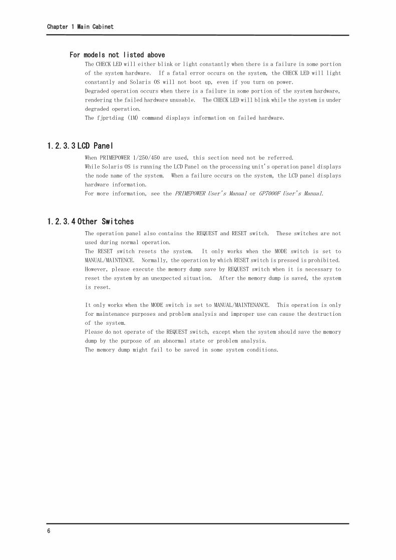
For models not listed above
The CHECK LED will either blink or light constantly when there is a failure in some portion
of the system hardware. If a fatal error occurs on the system, the CHECK LED will light
constantly and Solaris OS will not boot up, even if you turn on power.
Degraded operation occurs when there is a failure in some portion of the system hardware,
rendering the failed hardware unusable. The CHECK LED will blink while the system is under
degraded operation.
The fjprtdiag (1M) command displays information on failed hardware.
1.2.3.3 LCD Panel When PRIMEPOWER 1/250/450 are used, this section need not be referred.
While Solaris OS is running the LCD Panel on the processing unit's operation panel displays
the node name of the system. When a failure occurs on the system, the LCD panel displays
hardware information.
For more information, see the PRIMEPOWER User's Manual or GP7000F User's Manual.
1.2.3.4 Other Switches The operation panel also contains the REQUEST and RESET switch. These switches are not
used during normal operation.
The RESET switch resets the system. It only works when the MODE switch is set to
MANUAL/MAINTENCE. Normally, the operation by which RESET switch is pressed is prohibited.
However, please execute the memory dump save by REQUEST switch when it is necessary to
reset the system by an unexpected situation. After the memory dump is saved, the system
is reset.
It only works when the MODE switch is set to MANUAL/MAINTENANCE. This operation is only
for maintenance purposes and problem analysis and improper use can cause the destruction
of the system.
Please do not operate of the REQUEST switch, except when the system should save the memory
dump by the purpose of an abnormal state or problem analysis.
The memory dump might fail to be saved in some system conditions.
6
1.2 System Operation
1.2.4 Shutting Down and Booting the System
The system executes the shutdown process just like an operator in case of a system failure,
a manipulation of the Auto Power Control System, or the occurrence of other potential events.
If a UPS (Uninterruptible Power Supply) is connected, the system can also execute the
shutdown process if a power down occurs.
Whether the system will normally power on after a power down, depends on the following
conditions:
• The power to the system is cut according to the shutdown instruction of the operator
(executing shutdown -i5), the settings in the Auto Power Control System, or shutdown
due to system failure.
• Following a power down, when power is restored, the system will automatically power
on. But this will not occur if a system failure occurred during the shutdown process.
• Normally, the system reboots after the shutdown according to the reboot instruction
(executing shutdown -i6) of the operator. If a power down or a system failure occurs
during the shutdown process, the power to the system is cut off without a reboot
occurring.
7

Chapter 1 Main Cabinet
1.3 Server Setup This section describes how to set up the software to match the way the system will be
operated.
1.3.1 Changing PATH This software is installed on a different path than the normal Solaris OS commands, you
must change the PATH variable if commands, etc are used.
If the root shell is the Bourne shell, add the following line to /.profile. If /.profile
does not exist, create a new one.
PATH=$PATH:/opt/FJSVhwr/sbin
export PATH
If you are the super user by the su(1M) command, you will find it convenient to change
the SUPATH for /etc/default/su. The following is the default SUPATH for /etc/default/su:
# SUPATH sets the initial shell PATH variable for root
#
# SUPATH=/usr/sbin:/usr/bin
Set the SUPATH as follows:
# SUPATH sets the initial shell PATH variable for root
#
SUPATH=/usr/sbin:/usr/bin:/opt/FJSVhwr/sbin
1.3.2 Feature Settings
This section describes the software settings that must be made when setting up the server
or changing the system configuration.
However, the each feature settings might be unnecessary with the using model.
Feature that each model can be set with is shown in table 1.4, "Feature settings list of
each model."
8
1.3 Server Setup
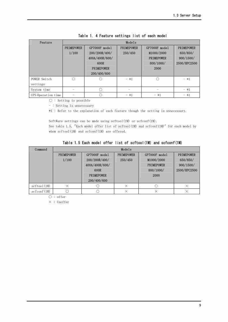
Table 1. 4 Feature settings list of each model
Models Feature
PRIMEPOWER
1/100
GP7000F model
200/200R/400/
400A/400R/600/
600R
PRIMEPOWER
200/400/600
PRIMEPOWER
250/450
GP7000F model
M1000/2000
PRIMEPOWER
800/1000/
2000
PRIMEPOWER
650/850/
900/1500/
2500/HPC2500
POWER Switch
settings
○ ○ - *1 ○ - *1
System time - ○ - - - *1
UPS Operation time - ○ - *1 - *1 - *1
○ : Setting is possible
- : Setting is unnecessary
*1 : Refer to the explanation of each feature though the setting is unnecessary.
SoftWare settings can be made using scftool(1M) or scfconf(1M).
See table 1.5, "Each model offer list of scftool(1M) and scfconf(1M)" for each model by
whom scftool(1M) and scfconf(1M) are offered.
Table 1.5 Each model offer list of scftool(1M) and scfconf(1M)
Models Command
PRIMEPOWER
1/100
GP7000F model
200/200R/400/
400A/400R/600/
600R
PRIMEPOWER
200/400/600
PRIMEPOWER
250/450
GP7000F model
M1000/2000
PRIMEPOWER
800/1000/
2000
PRIMEPOWER
650/850/
900/1500/
2500/HPC2500
scftool(1M) × ○ × ○ ×
scfconf(1M) ○ ○ × × ×
○ : offer
× : Unoffer
9
Chapter 1 Main Cabinet
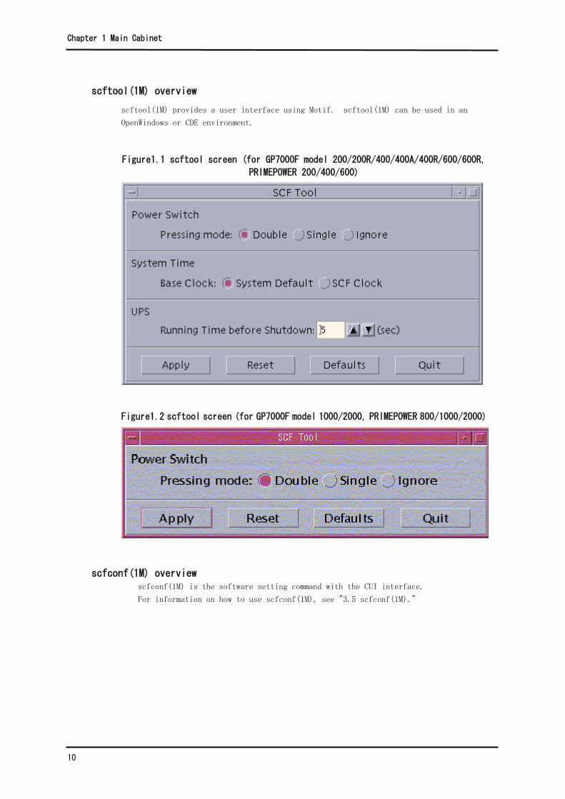
scftool(1M) overview
scftool(1M) provides a user interface using Motif. scftool(1M) can be used in an
OpenWindows or CDE environment.
Figure1.1 scftool screen (for GP7000F model 200/200R/400/400A/400R/600/600R,
PRIMEPOWER 200/400/600)
Figure1.2 scftool screen (for GP7000F model 1000/2000, PRIMEPOWER 800/1000/2000)
scfconf(1M) overview scfconf(1M) is the software setting command with the CUI interface.
For information on how to use scfconf(1M), see "3.5 scfconf(1M)."
10

1.3 Server Setup
1.3.2.1 POWER Switch Settings This software can be used to automatically shut down the system when the POWER switch is
pressed.
The default setting is to start the system shutdown process after the POWER switch has
been pressed twice.
Under the double-press mode, pressing the POWER switch twice will start the shutdown process.
This prevents the system from being shutdown by accidentally pressing the POWER switch
once. The first time the POWER switch is pressed; you will see a confirmation message
on the console. Pressing the POWER switch again within the seconds described to "1.2.2
Shutdown" will start the shutdown process.
Under the single-press mode, pressing the POWER switch will immediately start the shutdown
process without displaying the confirmation message.
Under the ignore mode, the system will not shutdown even when the POWER switch is pressed.
When the following models are used, default value is two times, and setting is not necessary.
• PRIMEPOWER 250/450/650/850/900/1500/2500/HPC2500
Notes When the POWER switch is continuously pressed more than the set value, compulsion power
supply OFF of the system might be executed.
Please do not press the POWER switch more than the set value continuously.
1.3.2.2 System Time For the following models, this section need not be referred to.
• GP7000F model 1000/2000
• PRIMEPOWER 1/100/250/450/800/900/1000/1500/2000/2500/HPC2500
This system has two hardware clocks: a system standard clock and the SCF high-resolution
clock that has a lower degree of error. This software makes it possible to use the SCF
high-resolution clock to adjust the time of the system standard clock.
The default setting uses only the system standard clock, and does not adjust its time.
Selecting the SCF high-resolution clock will cause time to be periodically adjusted,
allowing more accurate time operation. However, changing system time by date or a similar
command only affects the system standard clock. You must use the scfdate(1M) command to
synchronize the system standard clock and the SCF high-resolution clock. Do this by
executing the following:
# scfdate sync
Since system time can be changed by date(1) as well as stime(2), adjtime(2), and
settimeofday(3C), you must exercise caution when using the SCF high-resolution clock. In
particularly, do not use the SCF high-resolution clock when running NTP (Network Time
Protocol) software that utilizes the network to synchronize time.
You can use the scfdate(1M) command to display the current time of the SCF high-resolution
clock.
When the following models are used, the setting is unnecessary. However, when the system
time is changed, it is necessary to synchronize SCF high-resolution clock by the scfdate(1M)
command.
11
Chapter 1 Main Cabinet
• PRIMEPOWER 650/850
1.3.2.3 UPS Operation Time For the following models, this section need not be referred to because UPS cannot connect
by the UPS interface.
• PRIMEPOWER 1/100
Connecting a UPS (Uninterruptible Power Supply) to the system allows you to shut down the
system gracefully following a power down. In addition, if the power down is only for a
few seconds, you may not want a system shutdown. The system allows you to set the operation
time following a power down. This time is known as the UPS operation time.
UPS operation time is the length of delay prior to this software automatically starting
the shutdown process. It can be set from 0 second to 9999 seconds. The default delay is
5 seconds. If power returns within the UPS operation time, the system will continue to
operate.
UPS operation time is influenced by the UPS's capacity and specifications, time required
to shutdown the system, UPS charge level, and other factors. Make sure you perform through
tests before deciding on the appropriate UPS operation time.
When the following models are used, SCF driver does not have the setting. Set it by the
Machine Administration.
See the Machine Administration Guide for the setting method.
• GP7000F model 1000/2000
• PRIMEPOWER 250/450/650/800/850/900/1000/1500//2000/2500/HPC2500
1.3.2.4 Notes When GP7000 F model 1000/2000 or PRIMEPOWER 800/1000/2000 is used, and the SCF driver
package is installed reinstalling or updating, it is necessary to set up the SCF driver
again.
12

1.4 Troubleshooting
1.4 Troubleshooting To protect the system from being damaged, this software automatically shuts down and turns
off power when the fan fails, or an abnormal temperature is detected. To protect hardware
from damage, it also immediately turns off power when power supply failures are detected.
In this case however the system is not shut down.
With certain models redundant configurations enable continued operation even when one of
the redundant components fails, but note that the system will shut down to protect itself
if all of the redundant components fail.
When a component fails, a message is displayed on the console. You can also check for
failures using fjprtdiag(1M) and hsadm(1M).
13
Chapter 1 Main Cabinet
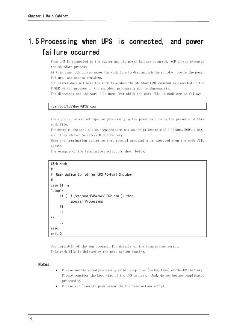
1.5 Processing when UPS is connected, and power failure occurred
When UPS is connected to the system and the power failure occurred, SCF driver executes
the shutdown process.
At this time, SCF driver makes the work file to distinguish the shutdown due to the power
failure, and starts shutdown.
SCF driver does not make the work file when the shutdown(1M) command is executed or the
POWER Switch presses or the shutdown processing due to abnormality.
The directory and the work file name from which the work file is made are as follows.
/var/opt/FJSVhwr/UPS2.cau
The application can add special processing by the power failure by the presence of this
work file.
For example, the application prepares termination script (example of filename: K00Action),
and it is stored to /etc/rc0.d directory.
Make the termination script so that special processing is executed when the work file
exists.
The example of the termination script is shown below.
#!/bin/sh
#
# User Action Script for UPS AC-Fail Shutdown
#
case $1 in
'stop')
if [ -f /var/opt/FJSVhwr/UPS2.cau ]; then
Special Processing
fi
;;
*)
;;
esac
exit 0
See init.d(4) of the Sun document for details of the termination script.
This work file is deleted by the next system booting.
Notes • Please end the added processing within keep time (backup time) of the UPS battery.
Please consider the keep time of the UPS battery. And, do not become complicated
processing.
• Please set "execute permission" to the termination script.
14

1.6 kernel parameter of SCF driver
1.6 kernel parameter of SCF driver
1.6.1 For SynfinityCluster When using SynfinityCluster, you need to set the SCF/RCI monitoring timeout in the kernel
parameter (/etc/system) according to RCI connecting unit model or the number of partitions.
Notes • The monitoring timeout might need to be set for some RCI connecting unit without
partitions.
• You can calculate the timeout using the largest number of partitions in an RCI
connecting unit.
• When the timeout setting is done, reboot a node and manually set the SynfinityCluster
parameter (failure detection monitoring time). See "5.3 Alert monitoring interval"
of the SynfinityCluster Installation/Administration Guide.
• Model with partitions: See "Condition a. "Model 800, 1000, and 2000".
• Model without partitions: See “Condition b. Cluster system with 4 or more nodes
except the above "a".
For GP7000F model 200/200R/400/400A/400R/600/600, and PRIMEPOWER200/400/600 The monitoring timeout setting is not required.
For PRIMEPOWER 250/450 Set 2 seconds for the monitoring timeout.
• Setting up the /etc/system file
Change the /etc/system file on all cluster nodes, as follows:
1) Copy (or backup) /etc/system using /etc/system.org:
Example: # cp /etc/system /etc/system.org
2) Add the following to /etc/system. As the timeout is set up in μs units, set
a value equal to the value calculated above, multiplied by 1000000:
set FJSVscf:scf_rdctrl_sense_wait = (monitoring timeout: μs unit)
For example: /etc/system is specified as follows:
set FJSVscf:scf_rdctrl_sense_wait = 2000000
3) Reboot the system
15
Chapter 1 Main Cabinet
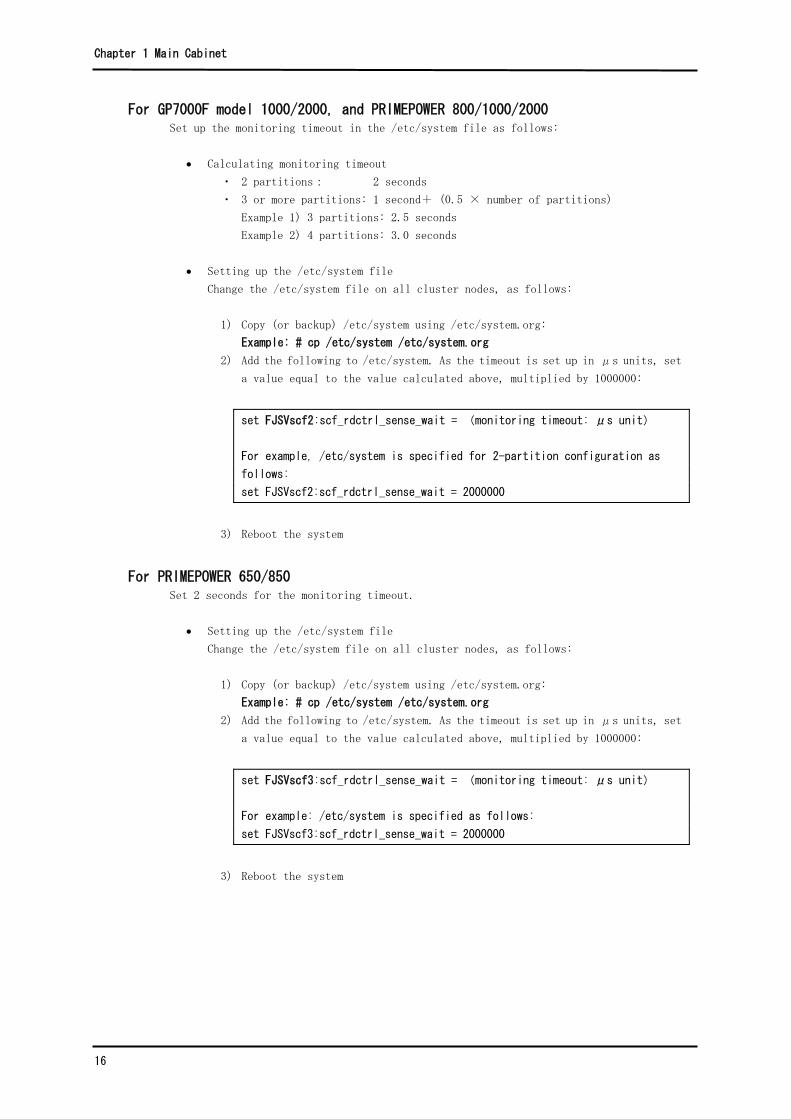
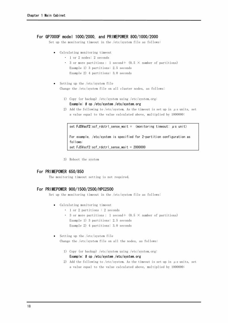
For GP7000F model 1000/2000, and PRIMEPOWER 800/1000/2000 Set up the monitoring timeout in the /etc/system file as follows:
• Calculating monitoring timeout
・ 2 partitions: 2 seconds
・ 3 or more partitions: 1 second+ (0.5 × number of partitions)
Example 1) 3 partitions: 2.5 seconds
Example 2) 4 partitions: 3.0 seconds
• Setting up the /etc/system file
Change the /etc/system file on all cluster nodes, as follows:
1) Copy (or backup) /etc/system using /etc/system.org:
Example: # cp /etc/system /etc/system.org
2) Add the following to /etc/system. As the timeout is set up in μs units, set
a value equal to the value calculated above, multiplied by 1000000:
set FJSVscf2:scf_rdctrl_sense_wait = (monitoring timeout: μs unit)
For example, /etc/system is specified for 2-partition configuration as
follows:
set FJSVscf2:scf_rdctrl_sense_wait = 2000000
3) Reboot the system
For PRIMEPOWER 650/850 Set 2 seconds for the monitoring timeout.
• Setting up the /etc/system file
Change the /etc/system file on all cluster nodes, as follows:
1) Copy (or backup) /etc/system using /etc/system.org:
Example: # cp /etc/system /etc/system.org
2) Add the following to /etc/system. As the timeout is set up in μs units, set
a value equal to the value calculated above, multiplied by 1000000:
set FJSVscf3:scf_rdctrl_sense_wait = (monitoring timeout: μs unit)
For example: /etc/system is specified as follows:
set FJSVscf3:scf_rdctrl_sense_wait = 2000000
3) Reboot the system
16
1.6 kernel parameter of SCF driver
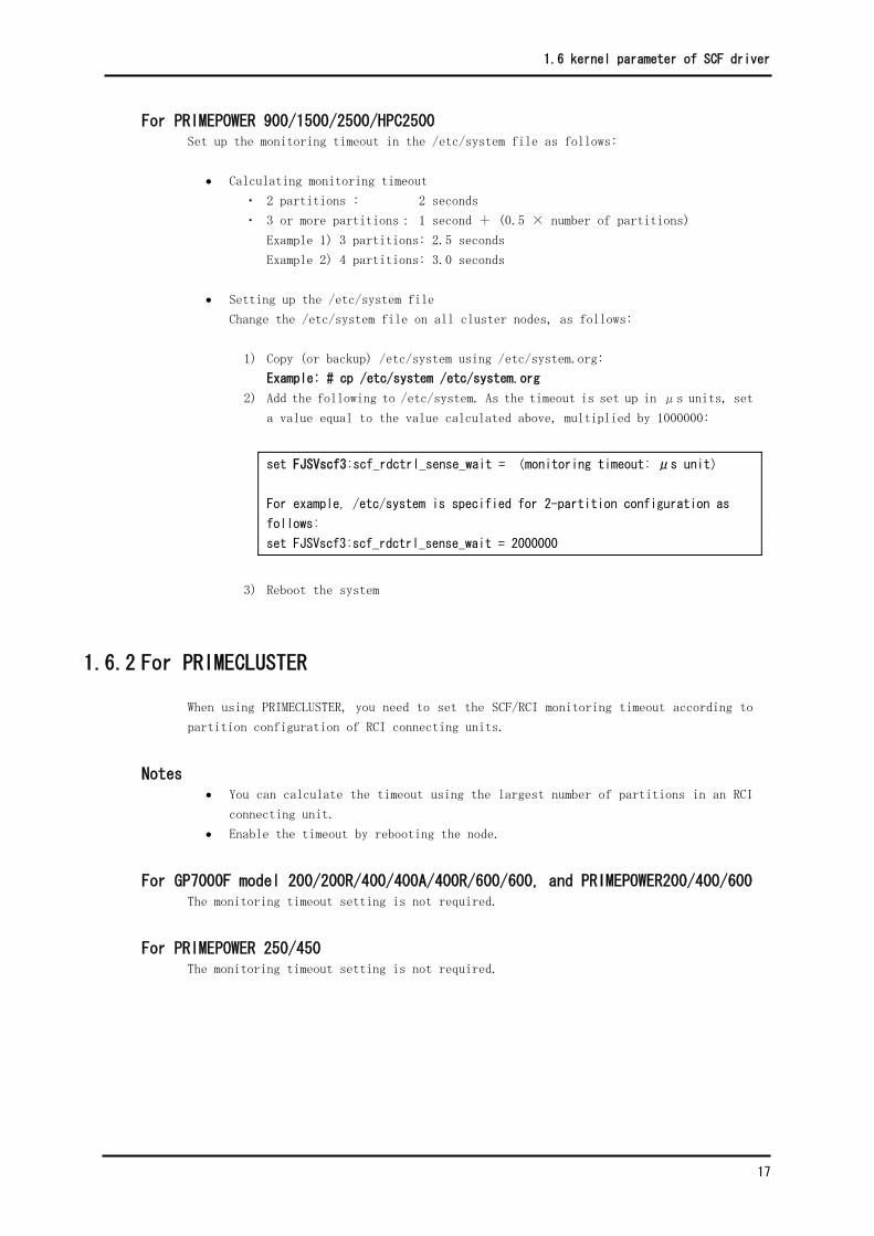
For PRIMEPOWER 900/1500/2500/HPC2500 Set up the monitoring timeout in the /etc/system file as follows:
• Calculating monitoring timeout
・ 2 partitions : 2 seconds
・ 3 or more partitions: 1 second + (0.5 × number of partitions)
Example 1) 3 partitions: 2.5 seconds
Example 2) 4 partitions: 3.0 seconds
• Setting up the /etc/system file
Change the /etc/system file on all cluster nodes, as follows:
1) Copy (or backup) /etc/system using /etc/system.org:
Example: # cp /etc/system /etc/system.org
2) Add the following to /etc/system. As the timeout is set up in μs units, set
a value equal to the value calculated above, multiplied by 1000000:
set FJSVscf3:scf_rdctrl_sense_wait = (monitoring timeout: μs unit)
For example, /etc/system is specified for 2-partition configuration as
follows:
set FJSVscf3:scf_rdctrl_sense_wait = 2000000
3) Reboot the system
1.6.2 For PRIMECLUSTER
When using PRIMECLUSTER, you need to set the SCF/RCI monitoring timeout according to
partition configuration of RCI connecting units.
Notes • You can calculate the timeout using the largest number of partitions in an RCI
connecting unit.
• Enable the timeout by rebooting the node.
For GP7000F model 200/200R/400/400A/400R/600/600, and PRIMEPOWER200/400/600 The monitoring timeout setting is not required.
For PRIMEPOWER 250/450 The monitoring timeout setting is not required.
17
Chapter 1 Main Cabinet
For GP7000F model 1000/2000, and PRIMEPOWER 800/1000/2000 Set up the monitoring timeout in the /etc/system file as follows:
• Calculating monitoring timeout
・ 1 or 2 nodes: 2 seconds
・ 3 or more partitions: 1 second+ (0.5 × number of partitions)
Example 1) 3 partitions: 2.5 seconds
Example 2) 4 partitions: 3.0 seconds
• Setting up the /etc/system file
Change the /etc/system file on all cluster nodes, as follows:
1) Copy (or backup) /etc/system using /etc/system.org:
Example: # cp /etc/system /etc/system.org
2) Add the following to /etc/system. As the timeout is set up in μs units, set
a value equal to the value calculated above, multiplied by 1000000:
set FJSVscf2:scf_rdctrl_sense_wait = (monitoring timeout: μs unit)
For example, /etc/system is specified for 2-partition configuration as
follows:
set FJSVscf2:scf_rdctrl_sense_wait = 2000000
3) Reboot the system
For PRIMEPOWER 650/850 The monitoring timeout setting is not required.
For PRIMEPOWER 900/1500/2500/HPC2500 Set up the monitoring timeout in the /etc/system file as follows:
• Calculating monitoring timeout
・ 1 or 2 partitions : 2 seconds
・ 3 or more partitions: 1 second+ (0.5 × number of partitions)
Example 1) 3 partitions: 2.5 seconds
Example 2) 4 partitions: 3.0 seconds
• Setting up the /etc/system file
Change the /etc/system file on all the nodes, as follows:
1) Copy (or backup) /etc/system using /etc/system.org:
Example: # cp /etc/system /etc/system.org
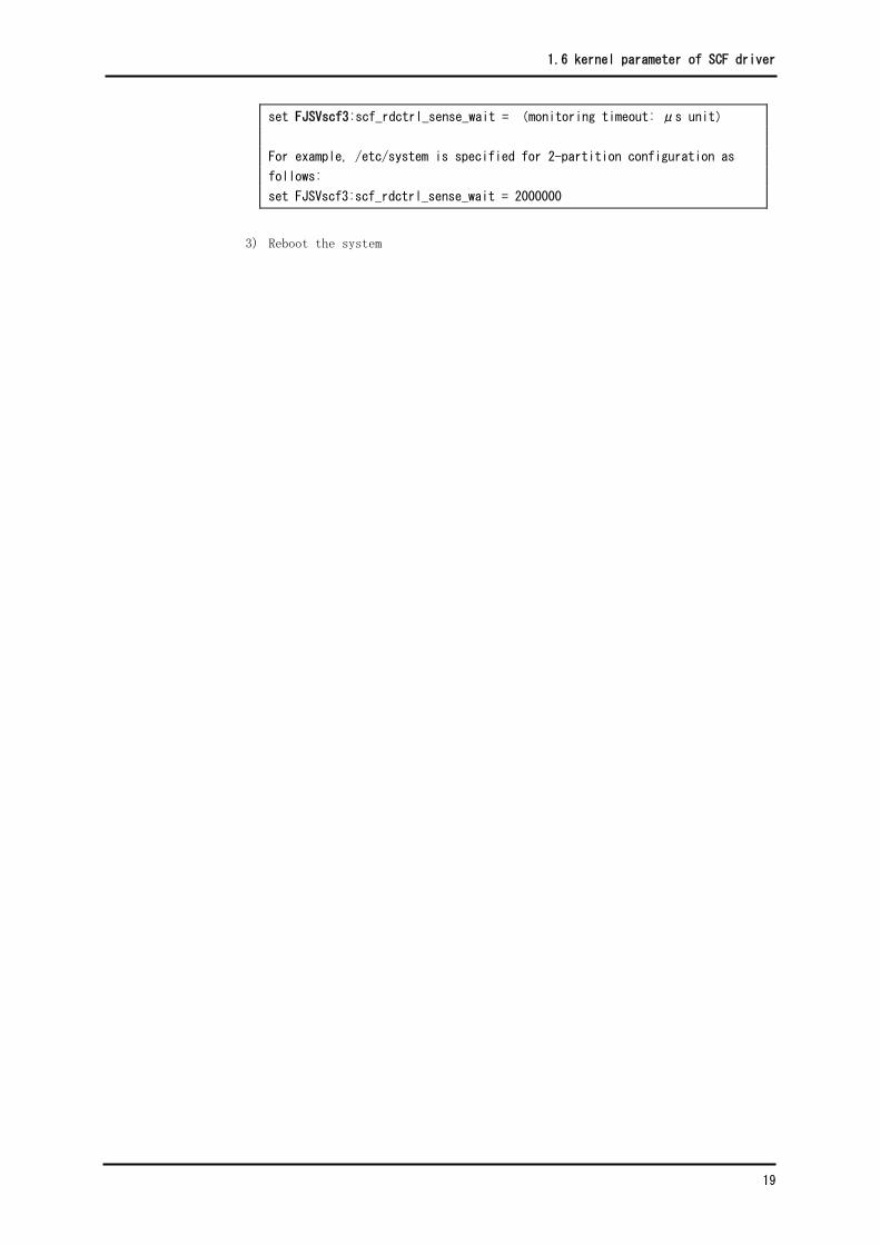
2) Add the following to /etc/system. As the timeout is set up in μs units, set
a value equal to the value calculated above, multiplied by 1000000:
18
1.6 kernel parameter of SCF driver
set FJSVscf3:scf_rdctrl_sense_wait = (monitoring timeout: μs unit)
For example, /etc/system is specified for 2-partition configuration as
follows:
set FJSVscf3:scf_rdctrl_sense_wait = 2000000
3) Reboot the system
19
Chapter 2 Expansion Disk
Cabinet/Expansion File Unit
This chapter describes the RAS (Reliability, Availability, and Serviceability) features
of the SCSI Expansion Disk Cabinet(at the following: Expansion Disk Cabinet) and SCSI
Expansion File Unit(at the following: Expansion File Unit).
2.1 Feature Overview
2.1 Feature Overview SCF driver offers the following RAS (Reliability, Availability, and Serviceability)
features of the Expansion Disk Cabinet/Expansion File Unit which connects RCI.
The following features are available.
When the SCSI Expansion File Unit without RCI, SCF driver offers only the hot-swapping
of internal disks.
• Notifies the system when power supply failures, abnormal temperatures or fan
breakdowns occur on Expansion Disk Cabinets/Expansion File Units.
This function is not offered to the following models.
・ PRIMEPOWER 1/100
• Allows the hot-swapping of redundant power supplies and fans on Expansion Disk
Cabinets/ Expansion File Units.
This function is not offered to the following models.
・ PRIMEPOWER 1/100
This function is available in the rcinodeadm(1M) command the following models offer.
・ GP7000F model 200/200R/400/400A/400R/600/600R
・ PRIMEPOWER 200/400/600
Models not listed above can be operated by the “Machine Administration” or “System
console”.
See the Machine Administration Guide or System Console Software User’s Guide.
• Allows the hot-swapping of internal disks on Expansion Disk Cabinets/ Expansion File
Units.
21

Chapter 2 Expansion Disk Cabinet/Expansion File Unit
2.2 Setup of Expansion Disk Cabinet/ Expansion File Unit
An SCSI Expansion Disk Cabinet/SCSI Expansion File Unit which connects RCI should be
included in the system before being used.
However, SCF does not provide commands to do this.
Moreover, the following models are off the subject of this function.
• PRIMEPOWER 1/100
As for including in the system, the operation is different because of each model.
For the following models, the RCI command that OBP(OpenBoot PROM) offers is used.
• GP7000F model 200/200R/400/400A/400R/600/600R
• PRIMEPOWER 200/250/400/450/600/650/850
See the PRIMEPOWER User's Manual or GP7000F User's Manual for information on how
to include the Expansion Disk Cabinet/Expansion File Unit using OBP RCI commands.
The following models are operated by “System Console”.
• GP7000F model 1000/2000
• PRIMEPOWER 800/900/1000/1500/2000/2500/HPC2500
See the PRIMEPOWER User's Manual, GP7000F USER'S MANUAL, or System Console Software
User's Guide.
When the Expansion File Unit without RCI is used, it need not be operated to include
it in the system.
Refer to the user's manual of the Expansion File Unit.
22

2.3 Troubleshooting
2.3 Troubleshooting SCF driver allows system notification of problems occurring in the SCSI Expansion Disk
Cabinet/SCSI Expansion File Unit, such as power supply failures, abnormal temperatures
or fan failures. Messages are displayed on the console in each case.
The system server will continue operation despite problems occurring in the Expansion Disk
Cabinet/Expansion File Unit, as SCF driver does not, in any case, shut down the system
server.
When it is impossible for the Expansion Disk Cabinet/Expansion File Unit to continue
operation due to abnormal temperatures or other potential problems, the hardware shuts
off power to the Expansion Disk Cabinet/Expansion File Unit after detecting the failures.
The Expansion Disk Cabinet/Expansion File Unit should be isolated, or other appropriate
steps should be taken, according to the messages and circumstances.
23
Chapter 3 Command Reference
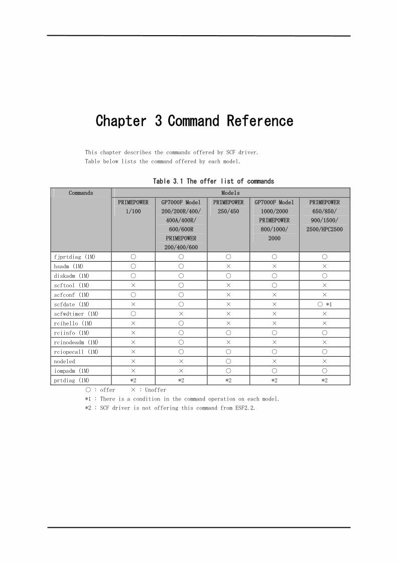
This chapter describes the commands offered by SCF driver.
Table below lists the command offered by each model.
Table 3.1 The offer list of commands
Models Commands
PRIMEPOWER
1/100
GP7000F Model
200/200R/400/
400A/400R/
600/600R
PRIMEPOWER
200/400/600
PRIMEPOWER
250/450
GP7000F Model
1000/2000
PRIMEPOWER
800/1000/
2000
PRIMEPOWER
650/850/
900/1500/
2500/HPC2500
fjprtdiag (1M) ○ ○ ○ ○ ○
hsadm (1M) ○ ○ × × ×
diskadm (1M) ○ ○ ○ ○ ○
scftool (1M) × ○ × ○ ×
scfconf (1M) ○ ○ × × ×
scfdate (1M) × ○ × × ○ *1
scfwdtimer (1M) ○ × × × ×
rcihello (1M) × ○ × × ×
rciinfo (1M) × ○ ○ ○ ○
rcinodeadm (1M) × ○ × × ×
rciopecall (1M) × ○ ○ ○ ○
nodeled × × ○ × ×
iompadm (1M) × × ○ ○ ○
prtdiag (1M) *2 *2 *2 *2 *2
○ : offer × : Unoffer
*1 : There is a condition in the command operation on each model.
*2 : SCF driver is not offering this command from ESF2.2.
3.1 fjprtdiag (1M)
3.1 fjprtdiag (1M)
NAME fjprtdiag - Prints system diagnostic information
SYNOPSIS /opt/FJSVhwr/sbin/fjprtdiag [ -v ] [ -l ]
AVAILABILITY FJSVscu, FJSVlscu, FJSVpscu, FJSVscu1, FJSVscu2, FJSVscu3
DESCRIPTION fjprtdiag displays system configuration information and system diagnostic information.
System diagnostic information includes information on degraded devices caused by failures.
The interface, output format, and installation location may change in future releases.
OPTIONS By default, fjprtdiag displays the following information:
• System Configuration
• System clock frequency
• Memory size
• Extended interleave mode (for PRIMEPOWER 650/850/900/1500/2500/HPC2500)
• CPU Units
• Used Memory
• Unused Memory (Displays when there is partial failure in memory used.)
• IO Cards
• Failed Units in System Initialization
• Detected Recent System faults
The following options are available:
-v
Verbose mode
Additionally displays detailed information that is environment information and OBP
version information.
"System Temperature" is not displayed in the following models.
・ PRIMEPOWER 1/100
・ GP7000F model 1000/2000, and PRIMEPOWER 800/1000/2000
・ PRIMEPOWER 900/1500/2500/HPC2500
-l
Log output
Outputs information to syslogd (1M) only when failures and errors occur on the system.
If it is specified along with -v, detailed information is always output to syslogd
(1M).
25
Chapter 3 Command Reference
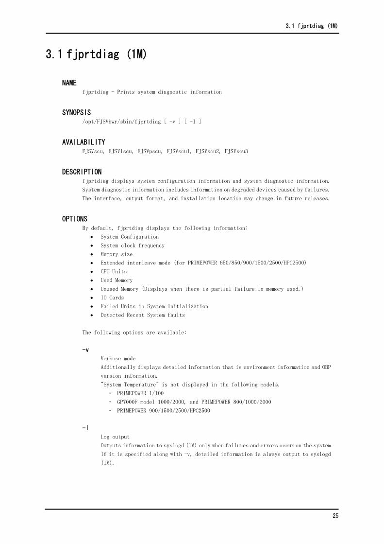
EXAMPLES The followings shows display examples for each model when the command is executed.
For PRIMEPOWER 1
% /opt/FJSVhwr/sbin/fjprtdiag
System Configuration:: Fujitsu/PFU sun4u Fujitsu PRIMEPOWER 1 1x UltraSPARC-IIe 400MHz
System clock frequency: 67 MHz
Memory size: 64Mb
CPU Units: Number Frequency Cache-Size Version
No. MHz MB Impl. Mask No. MHz MB Impl. Mask
----- ----- ----- ----- ----- ----- ----- ----- ----- -----
CPU#0 400 0.2 13 1.2
Used Memory: Slot-Number Size
No. MB No. MB No. MB No. MB
------- ----- ------- ----- ------- ----- ------- -----
SLOT0 64
====================================IO Cards===================================
Slot Name Model Bus(max freq.)
--------- ------------------------- --------------------------- ----------------
No failures found in System Initialization
==========================================
No Recent System Faults found
=============================
26

3.1 fjprtdiag (1M)
For GP7000F model 200/200R/400/400A/400R/600/600R and PRIMEPOWER 200/400/600
% /opt/FJSVhwr/sbin/fjprtdiag
System Configuration: Fujitsu/PFU sun4us Fujitsu PRIMEPOWER 200 1x SPARC64-III 272MHz
System clock frequency: 73 MHz
Memory size: 64Mb
CPU Units: Number Frequency Cache-Size Version
No. MHz MB Impl. Mask No. MHz MB Impl. Mask
----- ----- ----- ----- ----- ----- ----- ----- ----- -----
CPU#0 272 4.0 3 2.0
Used Memory: Slot-Number Size
No. MB No. MB No. MB No. MB
------- ----- ------- ----- ------- ----- ------- -----
SLOT0 32 SLOT1 32
==================================== IO Cards===================================
Slot Name Model Bus(max freq.)
---------- ------------------------ --------------------------- ----------------
PCI#6 scsi-glm Symbios,53C875 PCIBUS#D(33Mhz)
No failures found in System Initialization
==========================================
No Recent System Faults found
=============================
27

Chapter 3 Command Reference
For PRIMEPOWER 250/450
% /opt/FJSVhwr/sbin/fjprtdiag -v
System Configuration: Fujitsu sun4us Fujitsu PRIMEPOWER250 2x SPARC64 V
System clock frequency: 220 MHz
Memory size: 1024Mb
CPU Units: Number Frequency Cache-Size Version
No. MHz MB Impl. Mask No. MHz MB Impl. Mask
-------- ----- ----- ----- ----- -------- ----- ----- ----- -----
CPU#0 1100 4.0 4 0.7 CPU#1 1100 4.0 4 0.7
Used Memory: Slot-Number Size
No. MB No. MB No. MB No. MB
--------- ----- --------- ----- --------- ----- --------- -----
SLOT#0 256 SLOT#1 256 SLOT#2 256 SLOT#3 256
====================================IO Cards===================================
Slot Name Model max freq.
--------- ------------------------- --------------------------- ----------------
PCI#00 scsi-glm Symbios,53C875 33Mhz
PCI#01 SUNW,hme-pci108e,1001 SUNW,qsi-cheerio 33Mhz
No failures found in System Initialization
==========================================
No Recent System Faults found
=============================
===================== Environmental Status==========================================
MODE switch position is in MAINTE. mode
System Temperature (C):
AMBIENT 25
System PROM revisions:
----------------------
RST 1.1.4 2002/10/18 15:12 POST 1.1.3 2002/10/15 14:03
28

3.1 fjprtdiag (1M)
For GP7000F model 1000/2000 and PRIMEPOWER 800/1000/2000
% /opt/FJSVhwr/sbin/fjprtdiag -v
System Configuration: Fujitsu/PFU sun4us Fujitsu Siemens GP7000F 2000 2-slot 5x SPARC64
-III 300MHz
System clock frequency: 100 MHz
Memory size: 4096Mb
CPU Units: Number Frequency Cache-Size Version
No. MHz MB Impl. Mask No. MHz MB Impl. Mask
-------- ----- ----- ----- ----- -------- ----- ----- ----- -----
00-CPU#0 300 8.0 3 4.0 00-CPU#1 300 8.0 3 4.0
00-CPU#2 300 8.0 3 4.0
07-CPU#0 300 8.0 3 4.0 07-CPU#1 300 8.0 3 4.0
Used Memory: Slot-Number Size
No. MB No. MB No. MB No. MB
----------- ----- ----------- ----- ----------- ----- ----------- -----
00-SLOT#A00 128 00-SLOT#A01 128 00-SLOT#A02 128 00-SLOT#A03 128
00-SLOT#A10 128 00-SLOT#A11 128 00-SLOT#A12 128 00-SLOT#A13 128
00-SLOT#A20 128 00-SLOT#A21 128 00-SLOT#A22 128 00-SLOT#A23 128
00-SLOT#A30 128 00-SLOT#A31 128 00-SLOT#A32 128 00-SLOT#A33 128
07-SLOT#A00 128 07-SLOT#A01 128 07-SLOT#A02 128 07-SLOT#A03 128
07-SLOT#A10 128 07-SLOT#A11 128 07-SLOT#A12 128 07-SLOT#A13 128
07-SLOT#A20 128 07-SLOT#A21 128 07-SLOT#A22 128 07-SLOT#A23 128
07-SLOT#A30 128 07-SLOT#A31 128 07-SLOT#A32 128 07-SLOT#A33 128
====================================IO Cards===================================
Slot Name Model max freq.
--------- ------------------------- --------------------------- ----------------
00-PCI#0B scsi-glm Symbios,53C875 33Mhz
00-PCI#0A SUNW,hme-pci108e,1001 SUNW,qsi-cheerio 33Mhz
07-PCI#0B scsi-glm Symbios,53C875 33Mhz
07-PCI#1B pci-pci1011,24 33Mhz
No failures found in System Initialization
==========================================
No Recent System Faults found
=============================
===================== Environmental Status==========================================
MODE switch position is in LOCK mode
System PROM revisions:
----------------------
RST 3.11.1 1999/10/16 13:26 POST 1.1.8 1999/12/01 14:25
29
Chapter 3 Command Reference
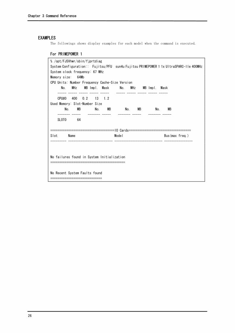
For PRIMEPOWER 650/850/900/1500/2500/HPC2500
% /opt/FJSVhwr/sbin/fjprtdiag -v
System Configuration: Fujitsu sun4us Fujitsu PRIMEPOWER850 2-slot 8x SPARC64 IV 675M
Hz
System clock frequency: 112 MHz
Memory size: 4096Mb
Extended Interleave Mode: Disable
CPU Units: Number Frequency Cache-Size Version
No. MHz MB Impl. Mask No. MHz MB Impl. Mask
----------- ----- ----- ----- ----- ----------- ----- ----- ----- -----
C0S00-CPU#0 675 8.0 4 0.7 C0S00-CPU#1 675 8.0 4 0.7
C0S00-CPU#2 675 8.0 4 0.7 C0S00-CPU#3 675 8.0 4 0.7
C0S01-CPU#0 675 8.0 4 0.7 C0S01-CPU#1 675 8.0 4 0.7
C0S01-CPU#2 675 8.0 4 0.7 C0S01-CPU#3 675 8.0 4 0.7
Used Memory: Slot-Number Size
No. MB No. MB
-------------- ----- -------------- -----
C0S00-SLOT#A00 256 C0S00-SLOT#B00 256
C0S00-SLOT#A01 256 C0S00-SLOT#B01 256
C0S00-SLOT#A02 256 C0S00-SLOT#B02 256
C0S00-SLOT#A03 256 C0S00-SLOT#B03 256
C0S01-SLOT#A00 256 C0S01-SLOT#B00 256
C0S01-SLOT#A01 256 C0S01-SLOT#B01 256
C0S01-SLOT#A02 256 C0S01-SLOT#B02 256
C0S01-SLOT#A03 256 C0S01-SLOT#B03 256
====================================IO Cards===================================
Sub Freq
Brd Brd Slot Name Model MHz
--- --- ------------ ------------------------- ---------------------------- ----
0 C0M00-PCI#00 scsi-glm Symbios,53C875 33
0 C0M00-PCI#01 SUNW,hme-pci108e,1001 SUNW,qsi-cheerio 33
No failures found in System Initialization
==========================================
No Recent System Faults found
=============================
===================== Environmental Status==========================================
MODE switch position is in LOCK mode
System Temperature (C):
AMBIENT 25
System PROM revisions:
----------------------
RST 1.1.18 2001/08/22 22:24 POST 1.1.11 2001/08/28 10:03
30

3.1 fjprtdiag (1M)
Notes Prtdiag (1M) command offered in before ESF2.1 is offered by fjprtdiag (1M) command in ESF2.2
or later.
When ESF2.2 or later is installed environment, please use this command.
Prtdiag (1M) command is installed in /usr/platform/`uname -i`/sbin directory.
However, the display format and the contents are quite different from fjprtdiag (1M)
command.
Please do not use /usr/platform/`uname -i`/sbin/prtdiag.
EXIT STATUS This command returns the following values:
0 No failures or errors detected on the system.
>0 Failures or errors detected on the system, or software errors detected.
SEE ALSO Uname (1), modinfo (1M), prtconf (1M), psrinfo (1M), sysdef (1M), syslogd (1M), openprom
(7D)
31

Chapter 3 Command Reference
3.2 hsadm (1M)
NAME hsadm - Supports hot-swapping of internal power units and fans
SYNOPSIS /opt/FJSVhwr/sbin/hsadm action unit
AVAILABILITY FJSVscu, FJSVlscu
DESCRIPTION hsadm supports the hot-swapping of internal power units and fans.
This command displays the state of power supplies and fans and starts/stops the monitoring
feature for both of those devices.
The command line must contain one action and at least one unit.
You can specify display, enable, or disable for action.
You can specify power and/or fan for unit.
The following models can use this command.
• GP7000F model 200/200R/400/400A/400R/600/600R
• PRIMEPOWER 1/100/200/400/600
EXAMPLES action
display unit Displays the status of the specified unit. The following shows the display format:
Power unit:
Monitoring Mode: On / Off
FEP#0 State: Okay / Needs maintenance
Fan unit:
Monitoring Mode: On / Off
FAN#0 State: Okay / Needs maintenance
disable unit Stops the monitoring feature for all specified units.
enable unit Restarts the monitoring feature for all specified units.
32

3.2 hsadm (1M)
NOTES While hot-swapping a power supply, hsadm(1M) command does not display the state of the
power supply which is removed.
After hot-swapping power supplies, use hsadm(1M) command to confirm that all of the power
supplies which are installed are in state Okay.
Note that only the super user can execute this command.
EXIT STATUS This command returns the following values:
0 Ended normally
1 Error
33
Chapter 3 Command Reference
3.3 diskadm (1M)
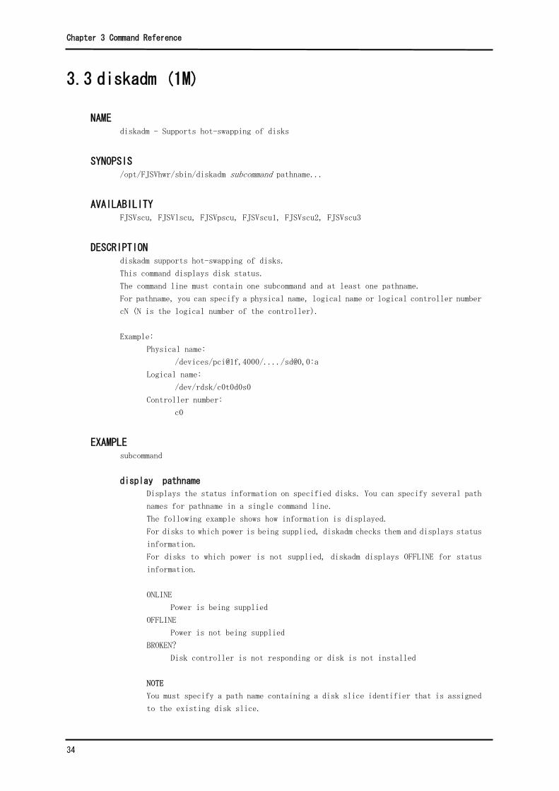
NAME diskadm - Supports hot-swapping of disks
SYNOPSIS /opt/FJSVhwr/sbin/diskadm subcommand pathname...
AVAILABILITY FJSVscu, FJSVlscu, FJSVpscu, FJSVscu1, FJSVscu2, FJSVscu3
DESCRIPTION diskadm supports hot-swapping of disks.
This command displays disk status.
The command line must contain one subcommand and at least one pathname.
For pathname, you can specify a physical name, logical name or logical controller number
cN (N is the logical number of the controller).
Example:
Physical name:
/devices/pci@1f,4000/..../sd@0,0:a
Logical name:
/dev/rdsk/c0t0d0s0
Controller number:
c0
EXAMPLE subcommand
display pathname
Displays the status information on specified disks. You can specify several path
names for pathname in a single command line.
The following example shows how information is displayed.
For disks to which power is being supplied, diskadm checks them and displays status
information.
For disks to which power is not supplied, diskadm displays OFFLINE for status
information.
ONLINE
Power is being supplied
OFFLINE
Power is not being supplied
BROKEN?
Disk controller is not responding or disk is not installed
NOTE
You must specify a path name containing a disk slice identifier that is assigned
to the existing disk slice.
34

3.3 diskadm (1M)
Controller specified. (Example: Installed target: 0, 2, 3, 4)
# diskadm display c0 <RETURN>
Controller is : /device/.... (c0)
Device Status:
Target0 Target2 Target3 Target4
ONLINE OFFLINE ONLINE ONLINE
Targets corresponding to existing device path are displayed.
Disk specified. (Example: Installed target: 0, 3)
# diskadm display /dev/rdsk/c0t0d0s2 /dev/rdsk/c0t3d0s2 <RETURN>
Controller is: /device/........
Device Status:
Target0 Target3
ONLINE OFFLINE
NOTES Only the super user can execute this command.
EXIT STATUS This command returns the following values:
0 Ended normally
1 Error
35
Chapter 3 Command Reference
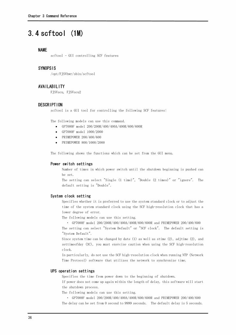
3.4 scftool (1M)
NAME scftool - GUI controlling SCF features
SYNOPSIS /opt/FJSVhwr/sbin/scftool
AVAILABILITY FJSVscu, FJSVscu2
DESCRIPTION scftool is a GUI tool for controlling the following SCF features:
The following models can use this command.
• GP7000F model 200/200R/400/400A/400R/600/600R
• GP7000F model 1000/2000
• PRIMEPOWER 200/400/600
• PRIMEPOWER 800/1000/2000
The following shows the functions which can be set from the GUI menu.
Power switch settings
Number of times in which power switch until the shutdown beginning is pushed can
be set.
The setting can select "Single (1 time)", "Double (2 times)" or "ignore". The
default setting is "Double".
System clock setting
Specifies whether it is preferred to use the system standard clock or to adjust the
time of the system standard clock using the SCF high-resolution clock that has a
lower degree of error.
The following models can use this setting.
・ GP7000F model 200/200R/400/400A/400R/600/600R and PRIMEPOWER 200/400/600
The setting can select "System Default" or "SCF clock". The default setting is
"System Default".
Since system time can be changed by date (1) as well as stime (2), adjtime (2), and
settimeofday (3C), you must exercise caution when using the SCF high-resolution
clock.
In particularly, do not use the SCF high-resolution clock when running NTP (Network
Time Protocol) software that utilizes the network to synchronize time.
UPS operation settings
Specifies the time from power down to the beginning of shutdown.
If power does not come up again within the length of delay, this software will start
the shutdown process.
The following models can use this setting.
・ GP7000F model 200/200R/400/400A/400R/600/600R and PRIMEPOWER 200/400/600
The delay can be set from 0 second to 9999 seconds. The default delay is 5 seconds.
36

3.4 scftool (1M)
NOTES Only the super user can execute this command.
When GP7000F model 1000/2000 and PRIMEPOWER 800/1000/2000 are used and "power switch
settings" is set to differ in each partition, the set value of each partition becomes
effective.
For example: When "Single" is specified for a certain partition and "Double" is
specified as for another partition, and if power switch is pushed only once, as for
the partition which specifies "Single" the shutdown is done.
EXIT STATUS This command returns the following values:
0 Ended normally
>0 Error
SEE ALSO Scfdate (1M)
37

Chapter 3 Command Reference
3.5 scfconf (1M)
NAME scfconf - CUI controlling SCF features
SYNOPSIS For PRIMEPOWER 1
/opt/FJSVhwr/sbin/scfconf [-p {1|2|off}]
For GP7000F model 200/200R/400/400A/400R/600/600R and PRIMEPOWER 200/400/600
/opt/FJSVhwr/sbin/scfconf [-p {1|2|off}] [-c {scf|tod}] [-u time]
AVAILABILITY FJSVscu, FJSVlscu
DESCRIPTION scfconf controls the following SCF features:
The following models can use this command.
• GP7000F model 200/200R/400/400A/400R/600/600R
• PRIMEPOWER 1/100/200/400/600
The following shows the functions which can be set by the command.
Power switch settings
Number of times in which power switch until the shutdown beginning is pushed can
be set.
The setting can select "1 (one time)", "2 (two times)" or "off (ignore)".
The default setting is "2". After power switch has been pressed twice, the shutdown
process is started.
System clock settings
Specifies whether it is preferred to use the system standard clock or to adjust the
time of the system standard clock using the SCF high-resolution clock that has a
lower degree of error.
The following models can use this setting.
・ GP7000F model 200/200R/400/400A/400R/600/600R and PRIMEPOWER 200/400/600
The setting can select "scf" or "tod". The default setting is "tod".
Since system time can be changed by date (1) as well as stime (2), adjtime (2), and
settimeofday (3C), you must exercise caution when using the SCF high-resolution
clock.
In particularly, do not use the SCF high-resolution clock when running NTP (Network
Time Protocol) software that utilizes the network to synchronize time.
38

3.5 scfconf (1M)
UPS operation settings
Specifies the time from power down to the beginning of shutdown.
If power does not come up again within the length of delay, this software will start
the shutdown process.
The following models can use this setting.
・ GP7000F model 200/200R/400/400A/400R/600/600R and PRIMEPOWER 200/400/600
The delay can be set from 0 second to 9999 seconds. The default delay is 5 seconds.
OPTIONS The following options are available. If no options are specified, the settings remain
unchanged.
-p 1 :
The system begins shutdown when the power switch is pressed once.
-p 2 :
The system begins shutdown when a power switch is pressed twice. You must press the
power switch again within 5 seconds before the first press is ignored.
-p off :
Pressing a power switch is always ignored.
-c scf :
Adjusts the time of the system standard clock using the SCF high-resolution clock.
This specification is specifiable with GP7000F model
200/200R/400/400A/400R/600/600R and PRIMEPOWER 200/400/600.
-c tod :
Only the system standard clock is used.
This specification is specifiable with GP7000F model
200/200R/400/400A/400R/600/600R and PRIMEPOWER 200/400/600.
-u time :
time: Specifies the length of delay in seconds until this software starts the
shutdown process.
This specification is specifiable with GP7000F model
200/200R/400/400A/400R/600/600R and PRIMEPOWER 200/400/600.
EXAMPLES # /opt/FJSVhwr/sbin/scfconf -p off -c scf
NOTES Only the super user can execute this command.
39

Chapter 3 Command Reference
EXIT STATUS This command returns the following values:
0 Ended normally
>0 Error
SEE ALSO Scfdate (1M),scftool (1M)
40

3.6 scfdate (1M)
3.6 scfdate (1M)
NAME scfdate - Checks the SCF high-resolution clock and synchronizes with the system standard
clock
SYNOPSIS /opt/FJSVhwr/sbin/scfdate [sync]
AVAILABILITY FJSVscu, FJSVscu3
DESCRIPTION scfdate checks the SCF high-resolution clock and then reads the time of the system standard
clock in order to reset the SCF high-resolution clock.
The following models can use this command.
• GP7000F model 200/200R/400/400A/400R/600/600R
• PRIMEPOWER 200/400/600/650/850
Running this command without any arguments displays the current time of the SCF
high-resolution clock.
Specifying the sync option sets system time from the system standard clock to the SCF
high-resolution clock.
Even if this command is offered to PRIMEPOWER 900/1500/2500/HPC2500, and specifies the
sync option, operation is invalid.
EXAMPLES
prompt% scfdate
Tue Oct 27 18:40:38 JST 1998
# date 1157
Tue Oct 27 11:57:00 JST 1998
# scfdate sync
Tue Oct 27 11:57:00 JST 1998
EXIT STATUS This command returns the following values:
0 Ended normally
>0 Error
41

Chapter 3 Command Reference
NOTES If you use scftool (1M) or scfconf (1M) to operate the system with the setting for using
the SCF high-resolution clock and you change system time with commands such as date (1),
you must synchronize the time of the SCF high-resolution clock. Note that only the super
user can execute the sync option of this command.
When the system is started in the single user mode, and system clock is changed, after
/opt directory is mounted by using maount (1M) and mountall (1M) this command can be
executed.
42
3.7 scfwdtimer (1M)
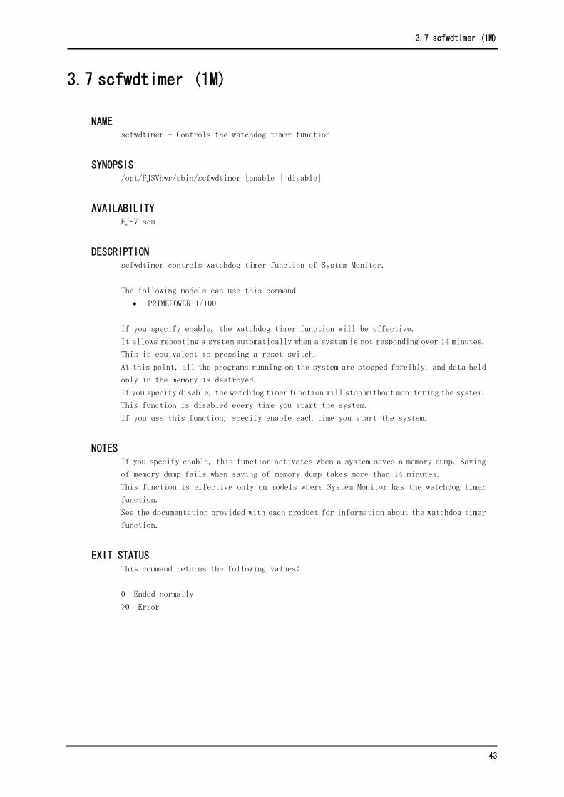
3.7 scfwdtimer (1M)
NAME scfwdtimer - Controls the watchdog timer function
SYNOPSIS /opt/FJSVhwr/sbin/scfwdtimer [enable | disable]
AVAILABILITY FJSVlscu
DESCRIPTION scfwdtimer controls watchdog timer function of System Monitor.
The following models can use this command.
• PRIMEPOWER 1/100
If you specify enable, the watchdog timer function will be effective.
It allows rebooting a system automatically when a system is not responding over 14 minutes.
This is equivalent to pressing a reset switch.
At this point, all the programs running on the system are stopped forcibly, and data held
only in the memory is destroyed.
If you specify disable, the watchdog timer function will stop without monitoring the system.
This function is disabled every time you start the system.
If you use this function, specify enable each time you start the system.
NOTES If you specify enable, this function activates when a system saves a memory dump. Saving
of memory dump fails when saving of memory dump takes more than 14 minutes.
This function is effective only on models where System Monitor has the watchdog timer
function.
See the documentation provided with each product for information about the watchdog timer
function.
EXIT STATUS This command returns the following values:
0 Ended normally
>0 Error
43

Chapter 3 Command Reference
3.8 rcihello (1M)
NAME rcihello - Controls CHECK LEDs of units connected via RCI
SYNOPSIS /opt/FJSVhwr/sbin/rcihello { on | off } [ address ]
AVAILABILITY FJSVscu
DESCRIPTION rcihello controls CHECK LEDs of units connected via RCI
The following models can use this command.
• GP7000F model 200/200R/400/400A/400R/600/600R
• PRIMEPOWER 200/400/600
OPTIONS The following options are available:
address
Specifies units to be controlled, which are connected via RCI. If no address is
specified, all of the units connected via RCI will be controlled. Addresses are
given in 8-digit hexadecimal.
on
Blinks CHECK LEDs
off
Stops blinking CHECK LEDs
EXAMPLES
# /opt/FJSVhwr/sbin/rcihello on 003001ff
NOTES The off option does not necessarily turn off CHECK LEDs. The CHECK LEDs with the addresses,
which you did not specify to blink on the rcihello command line, reflect the internal status
of the units connected via RCI.
Where old information remains on RCI devices that were previously connected, but currently
are not, rcihello executed with no address (control for all of the units connected via
RCI) will display error messages.
In this case, you must reconfigure RCI setting.
Note that only the super user can execute this command.
For the model by whom this command is not offered, "Machine Administration" offers the
function equal with this command. See the Machine Administration Guide.
44

3.8 rcihello (1M)
EXIT STATUS This command returns the following values:
0 Ended normally
>0 Error
SEE ALSO Rciinfo (1M), rcinodeadm (1M)
45
Chapter 3 Command Reference
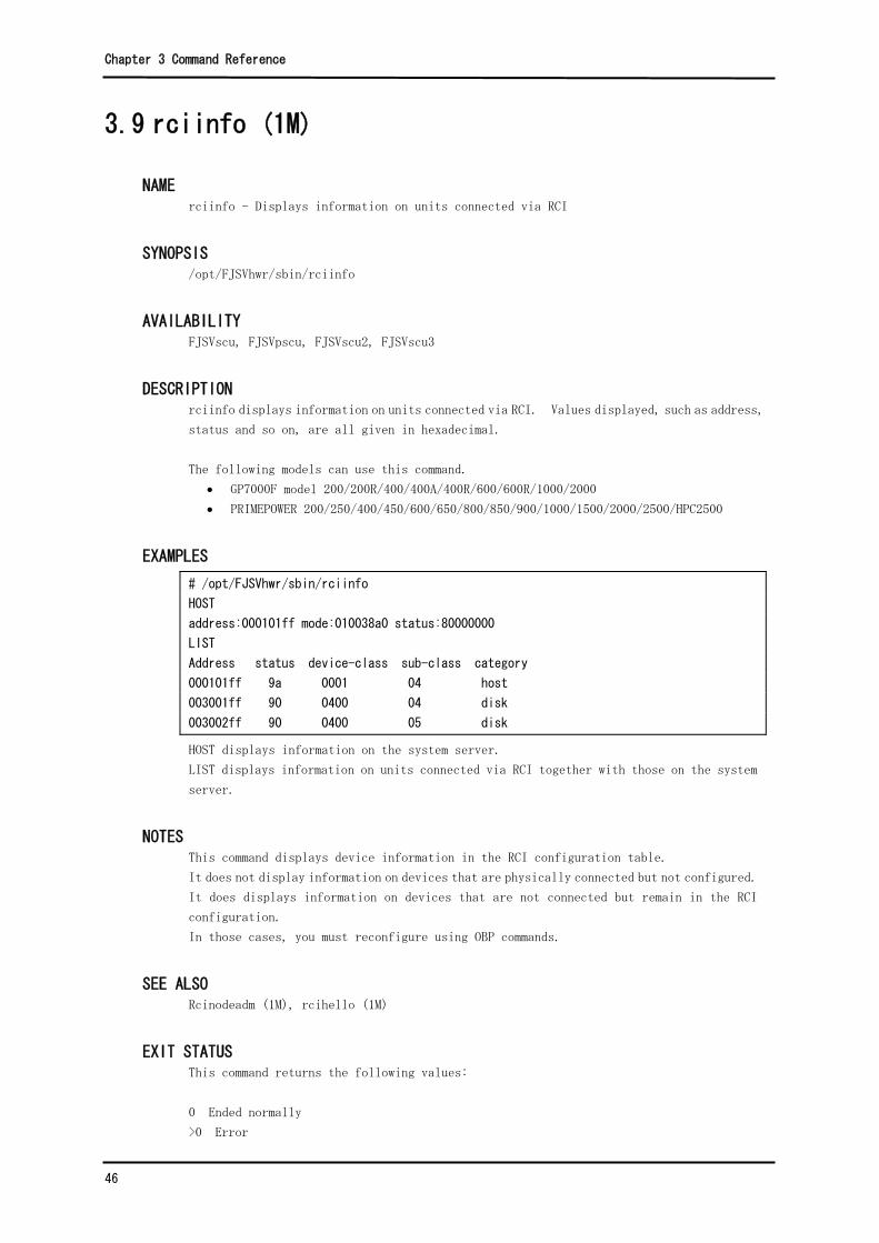
3.9 rciinfo (1M)
NAME rciinfo - Displays information on units connected via RCI
SYNOPSIS /opt/FJSVhwr/sbin/rciinfo
AVAILABILITY FJSVscu, FJSVpscu, FJSVscu2, FJSVscu3
DESCRIPTION rciinfo displays information on units connected via RCI. Values displayed, such as address,
status and so on, are all given in hexadecimal.
The following models can use this command.
• GP7000F model 200/200R/400/400A/400R/600/600R/1000/2000
• PRIMEPOWER 200/250/400/450/600/650/800/850/900/1000/1500/2000/2500/HPC2500
EXAMPLES
# /opt/FJSVhwr/sbin/rciinfo
HOST
address:000101ff mode:010038a0 status:80000000
LIST
Address status device-class sub-class category
000101ff 9a 0001 04 host
003001ff 90 0400 04 disk
003002ff 90 0400 05 disk
HOST displays information on the system server.
LIST displays information on units connected via RCI together with those on the system
server.
NOTES This command displays device information in the RCI configuration table.
It does not display information on devices that are physically connected but not configured.
It does displays information on devices that are not connected but remain in the RCI
configuration.
In those cases, you must reconfigure using OBP commands.
SEE ALSO Rcinodeadm (1M), rcihello (1M)
EXIT STATUS This command returns the following values:
0 Ended normally
>0 Error
46

3.10 rcinodeadm (1M)
3.10 rcinodeadm (1M)
NAME rcinodeadm - Controls monitoring units connected via RCI
SYNOPSIS /opt/FJSVhwr/sbin/rcinodeadm address action
AVAILABILITY FJSVscu
DESCRIPTION rcinodeadm supports the hot swapping of internal power supply and fan in the External Disk
Cabinet connected to the system server via RCI. This command starts/stops the monitoring
feature for both devices.
This command also operates fan test and turns off CHECK LEDs when monitoring is restarted.
The following models can use this command.
• GP7000F model 200/200R/400/400A/400R/600/600R
• PRIMEPOWER 200/400/600
OPTIONS address
Specifies addresses of units connected via RCI. You should specify addresses in
a format that rciinfo can display (that is 8-digit hexadecimal).
You can specify the following value for action.
disable
Stops monitoring units connected via RCI
enable
Restarts monitoring units connected via RCI
EXAMPLES
# /opt/FJSVhwr/sbin/rcinodeadm 003006ff disable
RCI 003006ff: alarm off
EXIT STATUS This command returns the following values:
0 Ended normally
>0 Error
47
Chapter 3 Command Reference
NOTES If the CHECK LED on RCI device is turned on due to self-detection of internal failures,
it stays lit after monitoring has restarted.
Note that only the super user can execute this command.
SEE ALSO rciinfo (1M), rcihello (1M)
48

3.11 rciopecall (1M)
3.11 rciopecall (1M)
NAME rciopecall - Reports operator call on units connected via RCI
SYNOPSIS /opt/FJSVhwr/sbin/rciopecall address {disp | on callNo | off callNo}
AVAILABILITY FJSVscu, FJSVpscu, FJSVscu1, FJSVscu2, FJSVscu3
DESCRIPTION rciopecall reports operator call on units connected via RCI.
The following models can use this command.
• GP7000F model 200/200R/400/400A/400R/600/600R/1000/2000
• PRIMEPOWER 200/250/400/450/600/650/800/850/900/1000/1500/2000/2500/HPC2500
OPTIONS The following options are available:
address
Specifies addresses of units connected via RCI. Addresses are given in 8-digit
hexadecimal.
You can specify the following value for action.
disp
Displays the operator call
on
Sets the operator call ON
off
Sets the operator call OFF
callNo
If "on" or "off" is specified for action, specifies callNo that controls the operator
call. callNo is given in 2-digit hexadecimal.
callNo is set up only in the device that "1" is specified in bit by the ON/OFF
designation. It is possible that more than one bit is specified at the same time.
EXAMPLES
# /opt/FJSVhwr/sbin/rciopecall 000101ff on 0c
# /opt/FJSVhwr/sbin/rciopecall 000101ff off 0c
# /opt/FJSVhwr/sbin/rciopecall 000101ff disp
address:000101ff callNo:0c status:00
49
Chapter 3 Command Reference
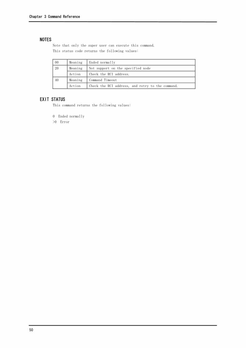
NOTES Note that only the super user can execute this command.
This status code returns the following values:
00 Meaning Ended normally
Meaning Not support on the specified node 20
Action Check the RCI address.
Meaning Command Timeout 40
Action Check the RCI address, and retry to the command.
EXIT STATUS This command returns the following values:
0 Ended normally
>0 Error
50

3.12 nodeled (1M)
3.12 nodeled (1M) NAME
nodeled – LED lamp control/status display command of this system
SYNOPSIS LED lamp control
/opt/FJSVhwr/sbin/nodeled [-led check] -mode on | blink | off
LED lamp status display
/opt/FJSVhwr/sbin/nodeled [-led check] -status
AVAILABILITY FJSVpscu
DESCRIPTION
This is a command to display the control and the state of the LED lamp of Main Cabinet.
In this command, the CHECK lamp of the Main Cabinet can be controlled.
To specify the target processor from remoteness at maintenance, the CHECK lamp is lit or
can be blinked by this command.
Moreover, status display of the CHECK lamp can be done.
The following models can use this command.
• PRIMEPOWER 250/450
OPTIONS The following options are available:
-led check
Specify the LED lamp. This parameter can be omitted.
check : CHECK lamp
-mode
Specify ON(lighting), BLINK(blinking), and OFF(release) of the LED lamp. This
parameter cannot be specified with "-status" parameter.
ON : LED lamp is lit
BLINK : LED lamp is blinked
OFF : Lighting or blinking the LED lamp is released. This parameter is returned
to the previous state to which the LED lamp is lit or blinked by this command.
-status
The state of the LED lamp is displayed. This parameter cannot be specified with
"-mode" parameter.
ON : State of lighting
BLINK : State of blinking
OFF : State of turning off
51

Chapter 3 Command Reference
EXAMPLES
# /opt/FJSVhwr/sbin/nodeled -led check -mode blink
# /opt/FJSVhwr/sbin/nodeled -led check -status
=== LED ====================
CHECK(Amber) ------ ON
EXIT STATUS This command returns the following values:
0 Ended normally
> 0 Error
52

3.13 iompadm (1M)
3.13 iompadm (1M) NAME
iompadm - Multipath control command
SYNOPSIS /usr/opt/FJSViomp/bin/iompadm [-p] -c class-name subcommand [parameter]
AVAILABILITY FJSVpscu, FJSVscu2, FJSVscu3, FJSViomp
DESCRIPTION iompadm displays the status of the communication paths composed of the interfaces.
This command also restores the communication path where a failure occurs.
You can display the status of communication paths or restore them using the combination
of the specified subcommand and parameter.
A communication path is a path that the SCF driver uses for communications with a SCF driver:
one communication path for each system board.
The following models can use this command.
• GP7000F model 1000/2000
• PRIMEPOWER 250/450/650/800/850/900/1000/1500/2000/2500/HPC2500
OPTIONS The following options are available:
-c calss-name
Specifies a class name.
For PRIMEPOWER 250/450
"FJSVscf" must be specified.
For GP7000F model 1000/2000 and PRIMEPOWER 800/1000/2000
"FJSVscf2" must be specified.
For PRIMEPOWER 650/850/900/1500/2500/HPC2500
"FJSVscf3" must be specified.
-p
Displays a communication path's logical and physical device name. If this option
is omitted, only the logical device name will be displayed.
53
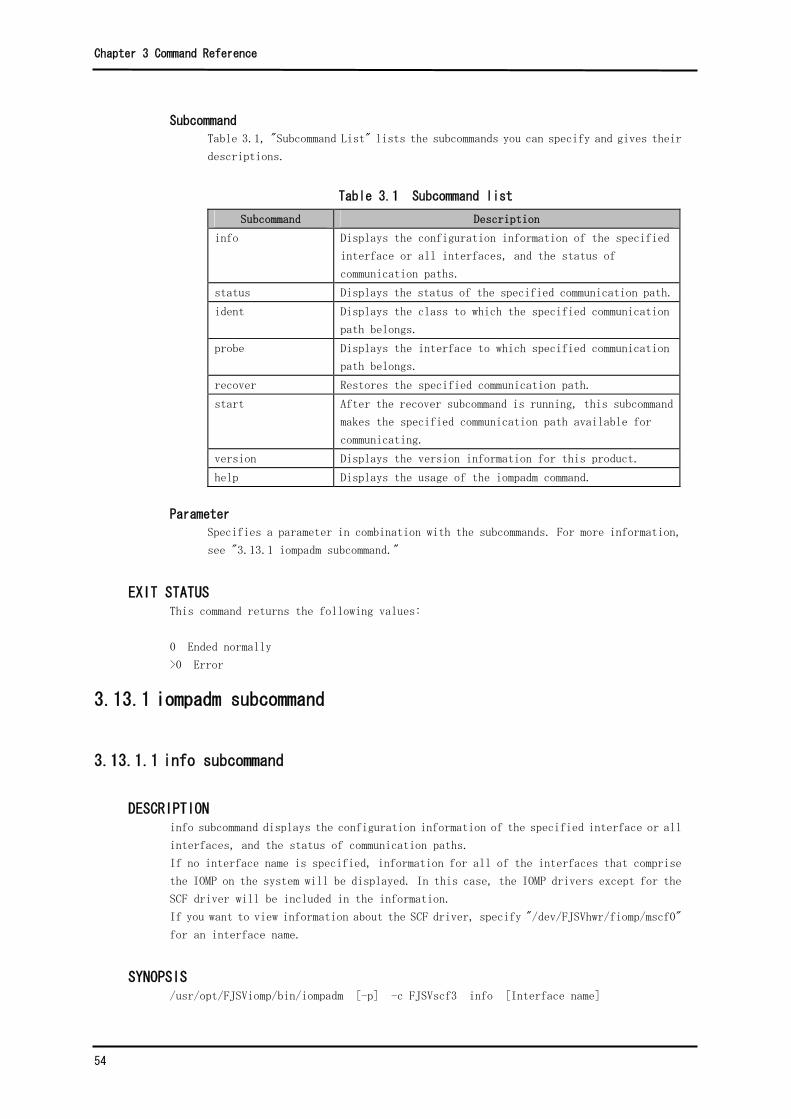
Chapter 3 Command Reference
Subcommand
Table 3.1, "Subcommand List" lists the subcommands you can specify and gives their
descriptions.
Table 3.1 Subcommand list
Subcommand Description
info Displays the configuration information of the specified
interface or all interfaces, and the status of
communication paths.
status Displays the status of the specified communication path.
ident Displays the class to which the specified communication
path belongs.
probe Displays the interface to which specified communication
path belongs.
recover Restores the specified communication path.
start After the recover subcommand is running, this subcommand
makes the specified communication path available for
communicating.
version Displays the version information for this product.
help Displays the usage of the iompadm command.
Parameter
Specifies a parameter in combination with the subcommands. For more information,
see "3.13.1 iompadm subcommand."
EXIT STATUS This command returns the following values:
0 Ended normally
>0 Error
3.13.1 iompadm subcommand
3.13.1.1 info subcommand
DESCRIPTION info subcommand displays the configuration information of the specified interface or all
interfaces, and the status of communication paths.
If no interface name is specified, information for all of the interfaces that comprise
the IOMP on the system will be displayed. In this case, the IOMP drivers except for the
SCF driver will be included in the information.
If you want to view information about the SCF driver, specify "/dev/FJSVhwr/fiomp/mscf0"
for an interface name.
SYNOPSIS /usr/opt/FJSViomp/bin/iompadm [-p] -c FJSVscf3 info [Interface name]
54
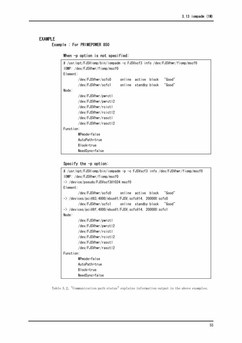
3.13 iompadm (1M)
EXAMPLE Example : For PRIMEPOWER 850
When -p option is not specified:
# /usr/opt/FJSViomp/bin/iompadm -c FJSVscf3 info /dev/FJSVhwr/fiomp/mscf0
IOMP: /dev/FJSVhwr/fiomp/mscf0
Element:
/dev/FJSVhwr/scfc0 online active block "Good"
/dev/FJSVhwr/scfc1 online standby block "Good"
Node:
/dev/FJSVhwr/pwrctl
/dev/FJSVhwr/pwrctl2
/dev/FJSVhwr/rcictl
/dev/FJSVhwr/rcictl2
/dev/FJSVhwr/rasctl
/dev/FJSVhwr/rasctl2
Function:
MPmode=false
AutoPath=true
Block=true
NeedSync=false
Specify the -p option:
# /usr/opt/FJSViomp/bin/iompadm -p -c FJSVscf3 info /dev/FJSVhwr/fiomp/mscf0
IOMP: /dev/FJSVhwr/fiomp/mscf0
-> /device/pseudo/FJSVscf3@1024:mscf0
Element:
/dev/FJSVhwr/scfc0 online active block "Good"
-> /devices/pci@83,4000/ebus@1/FJSV,scfc@14, 200000:scfc0
/dev/FJSVhwr/scfc1 online standby block "Good"
-> /devices/pci@8f,4000/ebus@1/FJSV,scfc@14, 200000:scfc1
Node:
/dev/FJSVhwr/pwrctl
/dev/FJSVhwr/pwrctl2
/dev/FJSVhwr/rcictl
/dev/FJSVhwr/rcictl2
/dev/FJSVhwr/rasctl
/dev/FJSVhwr/rasctl2
Function:
MPmode=false
AutoPath=true
Block=true
NeedSync=false
Table 3.2, "Communication path status" explains information output in the above examples.
55
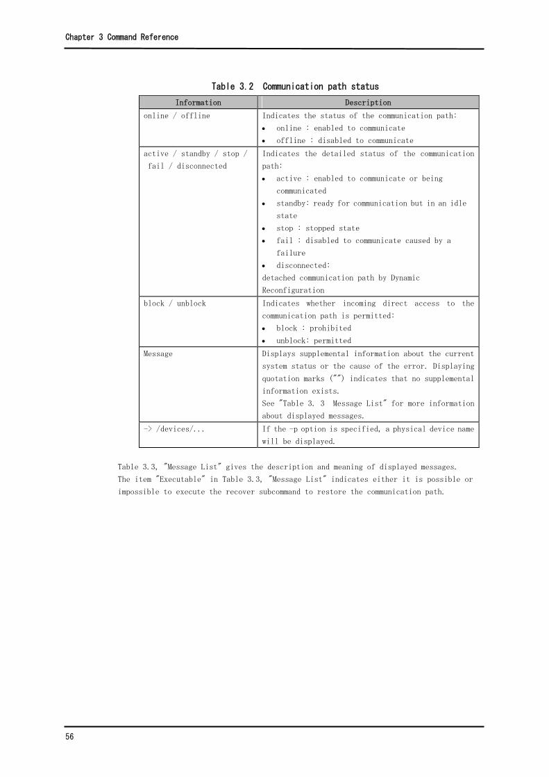
Chapter 3 Command Reference
Table 3.2 Communication path status
Information Description
online / offline Indicates the status of the communication path:
• online : enabled to communicate
• offline : disabled to communicate
active / standby / stop /
fail / disconnected
Indicates the detailed status of the communication
path:
• active : enabled to communicate or being
communicated
• standby: ready for communication but in an idle
state
• stop : stopped state
• fail : disabled to communicate caused by a
failure
• disconnected:
detached communication path by Dynamic
Reconfiguration
block / unblock Indicates whether incoming direct access to the
communication path is permitted:
• block : prohibited
• unblock: permitted
Message Displays supplemental information about the current
system status or the cause of the error. Displaying
quotation marks ("") indicates that no supplemental
information exists.
See "Table 3. 3 Message List" for more information
about displayed messages.
-> /devices/... If the -p option is specified, a physical device name
will be displayed.
Table 3.3, "Message List" gives the description and meaning of displayed messages.
The item "Executable" in Table 3.3, "Message List" indicates either it is possible or
impossible to execute the recover subcommand to restore the communication path.
56

3.13 iompadm (1M)
Table 3.3 Message list
Status Message Meaning Executable
active Good Communication is being established. -
standby Good The communication path is ready for
communication, but there is in an idle
state.
-
stop Good The communication path is being stopped. -
offline SCF device failure occurred. ×
Ebus2 Timeout Ebus2 Timeout occurred. ○
Command Error Send Sumcheck Error occurred. ○
Sumcheck Error Receive Sumcheck Error occurred. ○
Ebus2 DMA Error Ebus2 DMA transport error occurred. ○
Command Timeout SCF Command Timeout Error occurred. ○
fail
Parity error Parity Error occurred. ×
○: Possible (However, you might be impossible to restore the communication path
to work properly with the recover subcommand, depending upon the hardware failure.)
×: Impossible
-: Unnecessary
3.13.1.2 status subcommand DESCRIPTION
status subcommand displays the status of the specified communication path.
SYNOPSIS /usr/opt/FJSViomp/bin/iompadm [-p] -c class-name status Interface Name
[Communication Path Name]
EXAMPLE Example : For PRIMEPOWER 850
When -p option is not specified:
# /usr/opt/FJSViomp/bin/iompadm -c FJSVscf3 status /dev/FJSVhwr/fiomp/mscf0
/dev/FJSVhwr/scfc0 online active block "Good"
/dev/FJSVhwr/scfc1 online standby block "Good"
Specify the communication path name:
# /usr/opt/FJSViomp/bin/iompadm -c FJSVscf3 status /dev/FJSVhwr/fiomp/mscf0
/dev/FJSVhwr/scfc0
/dev/FJSVhwr/scfc0 online active block "Good"
57
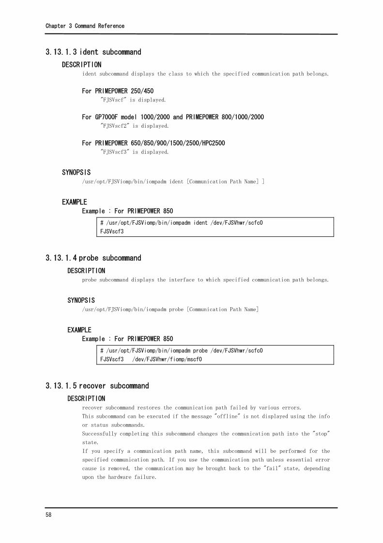
Chapter 3 Command Reference
3.13.1.3 ident subcommand DESCRIPTION
ident subcommand displays the class to which the specified communication path belongs.
For PRIMEPOWER 250/450
"FJSVscf" is displayed.
For GP7000F model 1000/2000 and PRIMEPOWER 800/1000/2000
"FJSVscf2" is displayed.
For PRIMEPOWER 650/850/900/1500/2500/HPC2500
"FJSVscf3" is displayed.
SYNOPSIS /usr/opt/FJSViomp/bin/iompadm ident [Communication Path Name]]
EXAMPLE Example : For PRIMEPOWER 850
# /usr/opt/FJSViomp/bin/iompadm ident /dev/FJSVhwr/scfc0
FJSVscf3
3.13.1.4 probe subcommand DESCRIPTION
probe subcommand displays the interface to which specified communication path belongs.
SYNOPSIS
/usr/opt/FJSViomp/bin/iompadm probe [Communication Path Name]
EXAMPLE
Example : For PRIMEPOWER 850
# /usr/opt/FJSViomp/bin/iompadm probe /dev/FJSVhwr/scfc0
FJSVscf3 /dev/FJSVhwr/fiomp/mscf0
3.13.1.5 recover subcommand DESCRIPTION
recover subcommand restores the communication path failed by various errors.
This subcommand can be executed if the message "offline" is not displayed using the info
or status subcommands.
Successfully completing this subcommand changes the communication path into the "stop"
state.
If you specify a communication path name, this subcommand will be performed for the
specified communication path. If you use the communication path unless essential error
cause is removed, the communication may be brought back to the "fail" state, depending
upon the hardware failure.
58
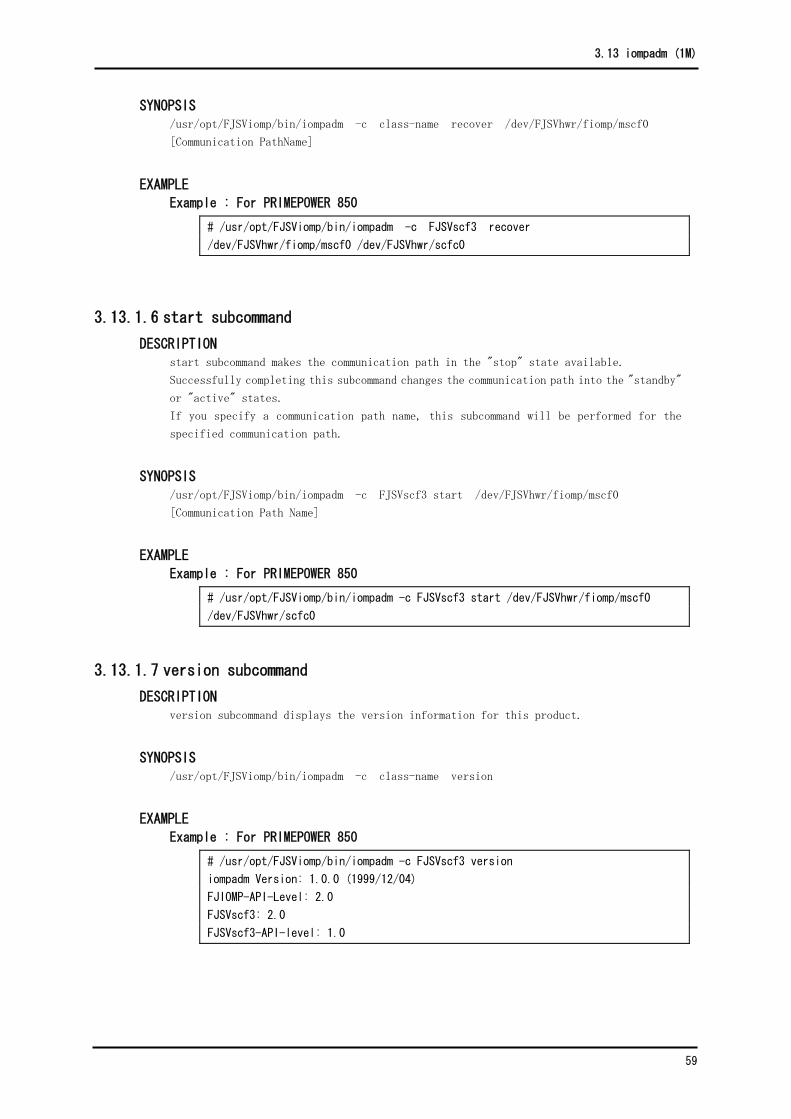
3.13 iompadm (1M)
SYNOPSIS
/usr/opt/FJSViomp/bin/iompadm -c class-name recover /dev/FJSVhwr/fiomp/mscf0
[Communication PathName]
EXAMPLE
Example : For PRIMEPOWER 850
# /usr/opt/FJSViomp/bin/iompadm -c FJSVscf3 recover
/dev/FJSVhwr/fiomp/mscf0 /dev/FJSVhwr/scfc0
3.13.1.6 start subcommand DESCRIPTION
start subcommand makes the communication path in the "stop" state available.
Successfully completing this subcommand changes the communication path into the "standby"
or "active" states.
If you specify a communication path name, this subcommand will be performed for the
specified communication path.
SYNOPSIS
/usr/opt/FJSViomp/bin/iompadm -c FJSVscf3 start /dev/FJSVhwr/fiomp/mscf0
[Communication Path Name]
EXAMPLE
Example : For PRIMEPOWER 850
# /usr/opt/FJSViomp/bin/iompadm -c FJSVscf3 start /dev/FJSVhwr/fiomp/mscf0
/dev/FJSVhwr/scfc0
3.13.1.7 version subcommand DESCRIPTION
version subcommand displays the version information for this product.
SYNOPSIS
/usr/opt/FJSViomp/bin/iompadm -c class-name version
EXAMPLE
Example : For PRIMEPOWER 850
# /usr/opt/FJSViomp/bin/iompadm -c FJSVscf3 version
iompadm Version: 1.0.0 (1999/12/04)
FJIOMP-API-Level: 2.0
FJSVscf3: 2.0
FJSVscf3-API-level: 1.0
59

Chapter 3 Command Reference
3.13.1.8 help subcommand DESCRIPTION
help subcommand displays the usage of the iompadm command.
SYNOPSIS
/usr/opt/FJSViomp/bin/iompadm -c class-name help
EXAMPLE
Example : For PRIMEPOWER 850
# /usr/opt/FJSViomp/bin/iompadm -c FJSVscf3 help
subcommand :
help Shows this help message.
ident Returns the class name for IOMP device.
info Returns information about an instance.
probe Returns class and instance name for IOMP device
recover Recovers the path after an error.
start Restarts the use of a path.
status Returns the path status.
version Shows versions.
usage :
iompadm [-p] [-c FJSVscf3] help
iompadm [-p] [-c FJSVscf3] ident device-name
iompadm [-p] [-c FJSVscf3] info [instance-name]
iompadm [-p] [-c FJSVscf3] probe device-name
iompadm [-p] [-c FJSVscf3] recover instance-name [device-name]
iompadm [-p] [-c FJSVscf3] start instance-name [device-name]
iompadm [-p] [-c FJSVscf3] status instance-name [device-name]
iompadm [-p] [-c FJSVscf3] version
60

3.14 prtdiag (1M)
3.14 prtdiag (1M) See fjprtdiag (1M).
prtdiag (1M) command offered in before ESF2.1 is offered by fjprtdiag (1M) command in ESF2.2
or later.
61
Chapter 4 Driver Messages
This chapter gives the meaning of messages displayed by the SCF driver of each model, and
meaning of messages displayed by other drivers of this software. It also describes what
to do when you get error messages.
The system call error messages listed below are described by man -s 2 Intro.
4.1 SCF driver
4.1 SCF driver Please see the message of the corresponding model for SCF driver's message.
4.1.1 For PRIMEPOWER 1
WARNING: FJSVscf: _init: ddi_soft_state_init failed.
Meaning
Failed to incorporate the SCF driver into the system due to the abnormal termination
of ddi_soft_state_init (9F).
Action
Allocate memory since there might not be enough kernel resources.
WARNING: FJSVscf: _init: mod_install failed.
Meaning
Failed to incorporate the SCF driver into the system due to the abnormal termination
of mod_install (9F) (incorporates the driver into the system).
Action
Allocate memory since there might not be enough kernel resources.
WARNING: FJSVscf: scf_attach: ddi_get_soft_state failed.
Meaning
Failed to incorporate the SCF driver into the system due to the abnormal termination
of ddi_get_soft_state (9F) (gets an area for the driver).
Action
Allocate memory since there might not be enough kernel resources.
WARNING: FJSVscf: scf_attach: ddi_soft_state_zalloc failed.
Meaning
Failed to incorporate the SCF driver into the system due to the abnormal termination
of ddi_soft_state_zalloc (9F) (allocates an area for the driver).
Action
Allocate memory since there might not be enough kernel resources.
WARNING: FJSVscf: scf_attach: ddi_get_iblock_cookie failed.
Meaning
Failed to incorporate the SCF driver into the system due to the abnormal termination
of ddi_get_iblock_cookie (9F) (allocates resources for interrupt processing).
Action
Allocate memory since there might not be enough kernel resources.
WARNING: FJSVscf: scf_attach: ddi_create_minor_node failed.
Meaning
Failed to incorporate the SCF driver into the system because the creation of the
device minor node failed.
Action
Make sure there is enough room in the /device file system.
63
Chapter 4 Driver Messages
WARNING: FJSVscf: scf_attach: ddi_add_intr failed.
Meaning
Failed to incorporate the SCF driver into the system due to the abnormal termination
of ddi_add_intr (9F) (registers interrupt functions).
Action
Allocate memory since there might not be enough kernel resources.
WARNING: FJSVscf: scf_attach() failed.
Meaning
Failed to incorporate the SCF driver into the system.
Action
Allocate memory since there might not be enough kernel resources.
WARNING: FJSVscf: scf_map_regs: ddi_regs_map_setup failed.
Meaning
Failed to incorporate the SCF driver into the system due to the abnormal termination
of ddi_regs_map_setup (9F) (maps register).
Action
Allocate memory since there might not be enough kernel resources.
WARNING: FJSVscf: scf_map_regs: ddi_dev_regsize failed.
Meaning
Failed to incorporate the SCF driver into the system due to the abnormal termination
of ddi_dev_regsize (9F) (gets the register size).
Action
Check the state of the System Monitor.
WARNING: FJSVscf: kstat_create failed
Meaning
kstat_create (9F) failed.
Action
Allocate memory since there might not be enough kernel resources.
WARNING: FJSVscf: scf_detach: ddi_get_soft_state failed
Meaning
Could not detach the SCF driver due to the abnormal termination of ddi_get_soft_state
(9F) (gets an area for the driver).
Action
Allocate memory since there might not be enough kernel resources.
WARNING: FJSVscf: scf_getinfo: ddi_get_soft_state failed
Meaning
Could not detach the SCF driver due to the abnormal termination of ddi_get_soft_state
(9F) (gets an area for the driver).
Action
Allocate memory since there might not be enough kernel resources.
64
4.1 SCF driver
WARNING: FJSVscf: scf_getinfo() failed
Meaning
getinfo failed.
Action
Allocate memory since there might not be enough kernel resources.
WARNING: FJSVscf: scf_open: ddi_get_soft_state failed
Meaning
Could not open the SCF driver due to the abnormal termination of ddi_get_soft_state
(9F) (gets an area for the driver).
Action
Allocate memory since there might not be enough kernel resources.
WARNING: FJSVscf: scf_read: ddi_get_soft_state failed
Meaning
Could not read the SCF driver due to the abnormal termination of ddi_get_soft_state
(9F) (gets an area for the driver).
Action
Allocate memory since there might not be enough kernel resources.
WARNING: FJSVscf: scf_ioctl: ddi_get_soft_state failed
Meaning
SCF driver ioctl failed due to the abnormal termination of ddi_get_soft_state (9F)
(gets an area for the driver).
Action
Allocate memory since there might not be enough kernel resources.
WARNING: FJSVscf: scf_intr: ddi_get_soft_state failed
Meaning
Could not detach the SCF driver due to the abnormal termination of ddi_get_soft_state
(9F) (gets an area for the driver).
Action
Allocate memory since there might not be enough kernel resources.
WARNING: FJSVscf: fan unit failure, FAN#?
Meaning
Detected a fan unit failure. FAN#? represents the fan unit number.
Action
Check the fan that had its number displayed.
WARNING: FJSVscf: power supply unit failure, FEP
Meaning
Detected a power supply unit failure.
Action
Check the power supply unit.
65

Chapter 4 Driver Messages
WARNING: FJSVscf: thermal alarm (X), SENSOR#?
Meaning
Detected an abnormal temperature.
X is a number representing the cause.
1 : Ambient temperature low temperature warning
2 : Ambient temperature low temperature alarm
3 : Ambient temperature high temperature warning
4 : Ambient temperature high temperature alarm
5 : Unit/Processor low temperature warning, or sensor failure
6 : Unit/Processor low temperature alarm, or sensor failure
7 : Unit/Processor high temperature warning
8 : unit/processor high temperature alarm
#? represents the sensor ID.
Action
Check the environment where the unit is set up. Also make sure there is nothing
wrong with the inside of the unit.
WARNING: FJSVscf: power supply unit failure
Meaning
Detected a power supply unit (DDC) failure.
Action
Check the power supply unit.
WARNING: FJSVscf: fan unit failure on power supply unit
Meaning
Detected a fan unit failure on power supply unit.
Action
Check the fan unit of power supply unit.
panic[cpuX]/thread=0xXXXXXXXX: FJSVscf: memory dumping due to pressing
REQUEST switch.
Meaning
Started saving memory dump due to the press of REQUEST switch
4.1.2 For GP7000F models 200/200R/400/400A/400R/600/600R and
PRIMEPOWER 200/400/600
WARNING: FJSVscf: _init: ddi_soft_state_init failed.
Meaning
Failed to incorporate the SCF driver into the system due to the abnormal termination
of ddi_soft_state_init (9F).
Action
Allocate memory since there might not be enough kernel resources.
66
4.1 SCF driver
WARNING: FJSVscf: _init: mod_install failed.
Meaning
Failed to incorporate the SCF driver into the system due to the abnormal termination
of mod_install (9F) (incorporates the driver into the system).
Action
Allocate memory since there might not be enough kernel resources.
WARNING: FJSVscf: scf_probe: ddi_soft_state_zalloc failed.
Meaning
Failed to incorporate the SCF driver into the system due to the abnormal termination
of ddi_soft_state_zalloc (9F) (allocates an area for the driver).
Action
Allocate memory since there might not be enough kernel resources.
WARNING: FJSVscf: scf_probe: ddi_get_soft_state failed.
Meaning
Failed to incorporate the SCF driver into the system due to the abnormal termination
of ddi_get_soft_state (9F) (gets an area for the driver).
Action
Allocate memory since there might not be enough kernel resources.
WARNING: FJSVscf: scf_probe: ddi_dev_nregs failed.
Meaning
The register information in the SCF device is incorrect.
Action
Check the state of the SCF device.
WARNING: FJSVscf: scf_attach: ddi_get_soft_state failed.
Meaning
Failed to incorporate the SCF driver into the system due to the abnormal termination
of ddi_get_soft_state (9F)(gets an area for the driver).
Action
Allocate memory since there might not be enough kernel resources.
WARNING: FJSVscf: scf_attach: ddi_soft_state_zalloc failed.
Meaning
Failed to incorporate the SCF driver into the system due to the abnormal termination
of ddi_soft_state_zalloc (9F) (allocates an area for the driver).
Action
Allocate memory since there might not be enough kernel resources.
WARNING: FJSVscf: scf_attach: ddi_get_soft_iblock_cookie failed.
Meaning
Failed to incorporate the SCF driver into the system due to the abnormal termination
of ddi_get_soft_iblock_cookie (9F) (allocates resources for interrupt processing).
Action
Allocate memory since there might not be enough kernel resources.
67

Chapter 4 Driver Messages
WARNING: FJSVscf: scf_attach: ddi_create_minor_node failed.
Meaning
Failed to incorporate the SCF driver into the system because the creation of the
device minor node failed.
Action
Make sure there is enough room in the /device file system.
WARNING: FJSVscf: scf_attach: ddi_add_intr failed.
Meaning
Failed to incorporate the SCF driver into the system due to the abnormal termination
of ddi_add_intr (9F) (registers interrupt functions).
Action
Allocate memory since there might not be enough kernel resources.
WARNING: FJSVscf: scf_map_regs: ddi_regs_map_setup failed.
Meaning
Failed to incorporate the SCF driver into the system due to the abnormal termination
of ddi_regs_map_setup (9F) (maps register).
Action
Allocate memory since there might not be enough kernel resources.
WARNING: FJSVscf: scf_map_regs: ddi_dev_regsize failed.
Meaning
Failed to incorporate the SCF driver into the system due to the abnormal termination
of ddi_dev_regsize (9F) (gets the register size).
Action
Check the state of the SCF device.
WARNING: FJSVscf: scf_chpoll: ddi_get_soft_state failed
Meaning
poll(2) terminated abnormally due to the abnormal termination of ddi_get_soft_state
(9F) (gets an area for the driver).
Action
Allocate memory since there might not be enough kernel resources.
WARNING: FJSVscf: scf_detach: ddi_get_soft_state failed
Meaning
Could not detach the SCF driver due to the abnormal termination of ddi_get_soft_state
(9F) (gets an area for the driver).
Action
Allocate memory since there might not be enough kernel resources.
WARNING: FJSVscf: scf_open: ddi_get_soft_state failed
Meaning
Could not open the SCF driver due to the abnormal termination of ddi_get_soft_state
(9F) (gets an area for the driver).
Action
Allocate memory since there might not be enough kernel resources.
68
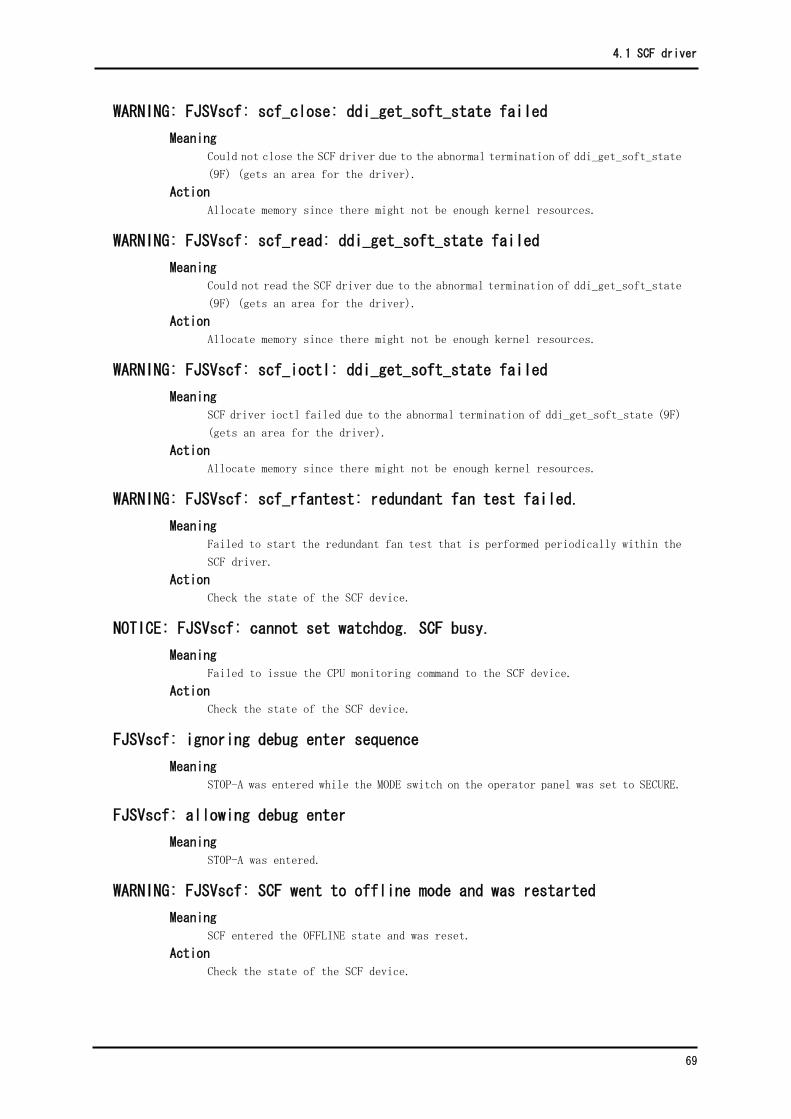
4.1 SCF driver
WARNING: FJSVscf: scf_close: ddi_get_soft_state failed
Meaning
Could not close the SCF driver due to the abnormal termination of ddi_get_soft_state
(9F) (gets an area for the driver).
Action
Allocate memory since there might not be enough kernel resources.
WARNING: FJSVscf: scf_read: ddi_get_soft_state failed
Meaning
Could not read the SCF driver due to the abnormal termination of ddi_get_soft_state
(9F) (gets an area for the driver).
Action
Allocate memory since there might not be enough kernel resources.
WARNING: FJSVscf: scf_ioctl: ddi_get_soft_state failed
Meaning
SCF driver ioctl failed due to the abnormal termination of ddi_get_soft_state (9F)
(gets an area for the driver).
Action
Allocate memory since there might not be enough kernel resources.
WARNING: FJSVscf: scf_rfantest: redundant fan test failed.
Meaning
Failed to start the redundant fan test that is performed periodically within the
SCF driver.
Action
Check the state of the SCF device.
NOTICE: FJSVscf: cannot set watchdog. SCF busy.
Meaning
Failed to issue the CPU monitoring command to the SCF device.
Action
Check the state of the SCF device.
FJSVscf: ignoring debug enter sequence
Meaning
STOP-A was entered while the MODE switch on the operator panel was set to SECURE.
FJSVscf: allowing debug enter
Meaning
STOP-A was entered.
WARNING: FJSVscf: SCF went to offline mode and was restarted
Meaning
SCF entered the OFFLINE state and was reset.
Action
Check the state of the SCF device.
69

Chapter 4 Driver Messages
NOTICE: FJSVscf: scf_reset: kmem_alloc failed. cannot dump firm area
Meaning
Failed to allocate memory and get a dump from the SCF device firmware area when the
SCF device was reset.
Action
Allocate memory since there might not be enough kernel resources.
NOTICE: FJSVscf: SCF online
Meaning
Resetting of the SCF device completed, and the device entered the ONLINE state.
WARNING: FJSVscf: scf_intr: Unexpected POFF interrupt occurred
Meaning
A POWER switch interrupt occurred while the toggle switch on the operator panel was
set to SECURE.
NOTICE: FJSVscf: AC power down (PFAIL)
Meaning
A cutoff in power supply was detected.
WARNING: FJSVscf: scf_intr: Unexpected EXTOD interrupt occurred
Meaning
Detected an EXTOD interrupt.
Action
Check the state of the SCF device.
WARNING: FJSVscf: fan unit failure, FAN#?
Meaning
Detected a fan unit failure. FAN#? represents the fan unit number.
Action
Check the fan that had its number displayed.
WARNING: FJSVscf: power supply unit failure, FEP#?
Meaning
Detected a power supply unit failure. FEP#? represents the power supply unit
number.
Action
Check the power supply unit that had its number displayed.
70

4.1 SCF driver
WARNING: FJSVscf: thermal alarm (X), SENSOR#?
Meaning
Detected an abnormal temperature.
X is a number representing the cause.
1 : Ambient temperature low temperature warning
2 : Ambient temperature low temperature alarm
3 : Ambient temperature high temperature warning
4 : Ambient temperature high temperature alarm
5 : Unit/Processor low temperature warning, or sensor failure
6 : Unit/Processor low temperature alarm, or sensor failure
7 : Unit/Processor high temperature warning
8 : unit/processor high temperature alarm
#? represents the sensor ID.
Action
Check the environment where the unit is set up. Also make sure there is nothing
wrong with the inside of the unit.
WARNING: FJSVscf: AC power down was detected. UPS is activated.
Meaning
Power is now being supplied by the UPS due to a power down.
FJSVscf: AC power recovered
Meaning
Power was restored.
WARNING: FJSVscf: UPS low battery, UPS#?
Meaning
Power from the UPS has run out. UPS#? represents the UPS number.
Action
Charge the UPS battery.
WARNING: FJSVscf: UPS failure, UPS#?
Meaning
Detected a UPS failure (either a UPS hardware failure, UPS failure, or UPS circuit
protector failure). UPS#? represents the UPS number.
Action
Check to make sure that nothing is wrong with the UPS.
WARNING: FJSVscf: SCF battery alarm, BATTERY#?
Meaning
Problem detected in the battery backing up SCF SRAM. #? represents the battery
number.
Action
Check the battery.
71

Chapter 4 Driver Messages
NOTICE: FJSVscf: caught cpu watchdog alarm
Meaning
A CPU monitoring timeout occurred during CPU monitoring.
Action
Allocate memory since there might not be enough kernel resources.
NOTICE: FJSVscf: device sense Sub Code = 0x? is not support
Meaning
The SCF device reported sensor information that is not supported by the driver. 0x?
represents the sub code of the sensor information that was reported.
Action
Check the state of the SCF device.
WARNING: FJSVscf: scf cmd (0x?) incomplete
Meaning
The SCF device could not complete a command within the prescribed time. 0x?
represents the command code that could not be completed.
Action
Check the state of the SCF device.
WARNING: FJSVscf: scf cmd (0x?) failed. SCF hard error
Meaning
The command could not complete successfully on the SCF device due to a hardware error.
0x? represents the command code that ended in an error.
Action
Check the state of the SCF device.
WARNING: FJSVscf: scf cmd (0x?) failed. SCF RCI error
Meaning
The command could not complete successfully on the SCF device due to an RCI error.
0x? represents the command code that ended in an error.
Action
Check the state of the SCF device.
WARNING: FJSVscf: scf cmd (0x?) failed by unknown error (yy)
Meaning
The command could not complete successfully on the SCF device due to an undefined
error. 0x? represents the command code that ended in an error and yy is the error
code on the SCF device.
Action
Check the state of the SCF device.
WARNING: FJSVscf: SCF hardware error was detected (error status register
value)
Meaning
SCF hardware error occurred.
Action
If this message was issued repeatedly, check the SCF device.
72
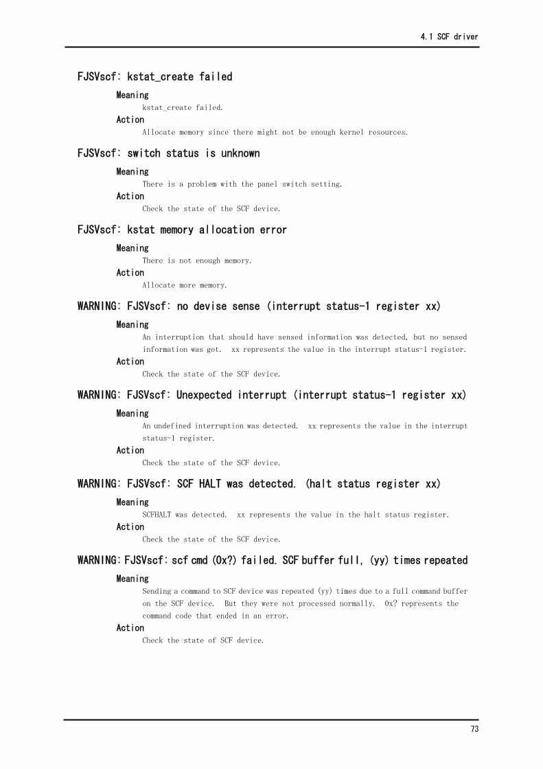
4.1 SCF driver
FJSVscf: kstat_create failed
Meaning
kstat_create failed.
Action
Allocate memory since there might not be enough kernel resources.
FJSVscf: switch status is unknown
Meaning
There is a problem with the panel switch setting.
Action
Check the state of the SCF device.
FJSVscf: kstat memory allocation error
Meaning
There is not enough memory.
Action
Allocate more memory.
WARNING: FJSVscf: no devise sense (interrupt status-1 register xx)
Meaning
An interruption that should have sensed information was detected, but no sensed
information was got. xx represents the value in the interrupt status-1 register.
Action
Check the state of the SCF device.
WARNING: FJSVscf: Unexpected interrupt (interrupt status-1 register xx)
Meaning
An undefined interruption was detected. xx represents the value in the interrupt
status-1 register.
Action
Check the state of the SCF device.
WARNING: FJSVscf: SCF HALT was detected. (halt status register xx)
Meaning
SCFHALT was detected. xx represents the value in the halt status register.
Action
Check the state of the SCF device.
WARNING: FJSVscf: scf cmd (0x?) failed. SCF buffer full, (yy) times repeated
Meaning
Sending a command to SCF device was repeated (yy) times due to a full command buffer
on the SCF device. But they were not processed normally. 0x? represents the
command code that ended in an error.
Action
Check the state of SCF device.
73

Chapter 4 Driver Messages
WARNING: FJSVscf: scf_map_regs: ddi_dev_regsize failed. (Ebus T.O.
register)
Meaning
ddi_dev_regsize (9F) (gets register size) terminated abnormally.
Action
Check to make sure that nothing is wrong with the hardware (Ebus).
WARNING: FJSVscf: scf_map_regs: ddi_regs_map_setup failed. (Ebus T.O.
register)
Meaning
ddi_regs_map_setup(9F) (maps register) terminated abnormally.
Action
Allocate memory since there might not be enough kernel resources.
WARNING: FJSVscf: scf_icotl: Status Check Timeout Control command timeout
Meaning
The Status Check Timeout Control command of the SCF could not complete within the
prescribed time.
Action
Check the state of the SCF device.
WARNING: FJSVscf: EBus TimeOut. EBus T.O. Status register = 0x?.
Meaning
A Ebus timeout occurred. ? represents the value in the Ebus Timeout Status register.
Action
Check to make sure that nothing is wrong with the hardware(Ebus).
WARNING: FJSVscf: scf_intr: cannot get p-off factor.
Meaning
Could not get the power on/off factor from the SCF.
Action
Check the state of the SCF device.
panic[cpuX]/thread=0xXXXXXXXX: FJSVscf: panic request from RCI 0xXXXXXXXX
Meaning
The RCI device that has RCI address of ? requested the system panic.
Action
This message shows the state.
However, at the cluster environment etc. , another node (RCI address 0xXXXXXXXX)
which detected abnormality issues the panic instruction to this node via RCI. And,
when OS panic is executed, this node outputs this message.
Please investigate this node from information on another node (RCI address
0xXXXXXXXX).
74
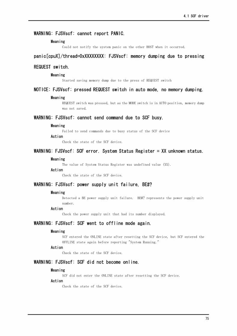
4.1 SCF driver
WARNING: FJSVscf: cannot report PANIC.
Meaning
Could not notify the system panic on the other HOST when it occurred.
panic[cpuX]/thread=0xXXXXXXXX: FJSVscf: memory dumping due to pressing
REQUEST switch.
Meaning
Started saving memory dump due to the press of REQUEST switch
NOTICE: FJSVscf: pressed REQUEST switch in auto mode, no memory dumping.
Meaning
REQUEST switch was pressed, but as the MODE switch is in AUTO position, memory dump
was not saved.
WARNING: FJSVscf: cannot send command due to SCF busy.
Meaning
Failed to send commands due to busy status of the SCF device
Action
Check the state of the SCF device.
WARNING: FJSVscf: SCF error. System Status Register = XX unknown status.
Meaning
The value of System Status Register was undefined value (XX).
Action
Check the state of the SCF device.
WARNING: FJSVscf: power supply unit failure, BE#?
Meaning
Detected a BE power supply unit failure. BE#? represents the power supply unit
number.
Action
Check the power supply unit that had its number displayed.
WARNING: FJSVscf: SCF went to offline mode again.
Meaning
SCF entered the ONLINE state after resetting the SCF device, but SCF entered the
OFFLINE state again before reporting "System Running."
Action
Check the state of the SCF device.
WARNING: FJSVscf: SCF did not become online.
Meaning
SCF did not enter the ONLINE state after resetting the SCF device.
Action
Check the state of the SCF device.
75
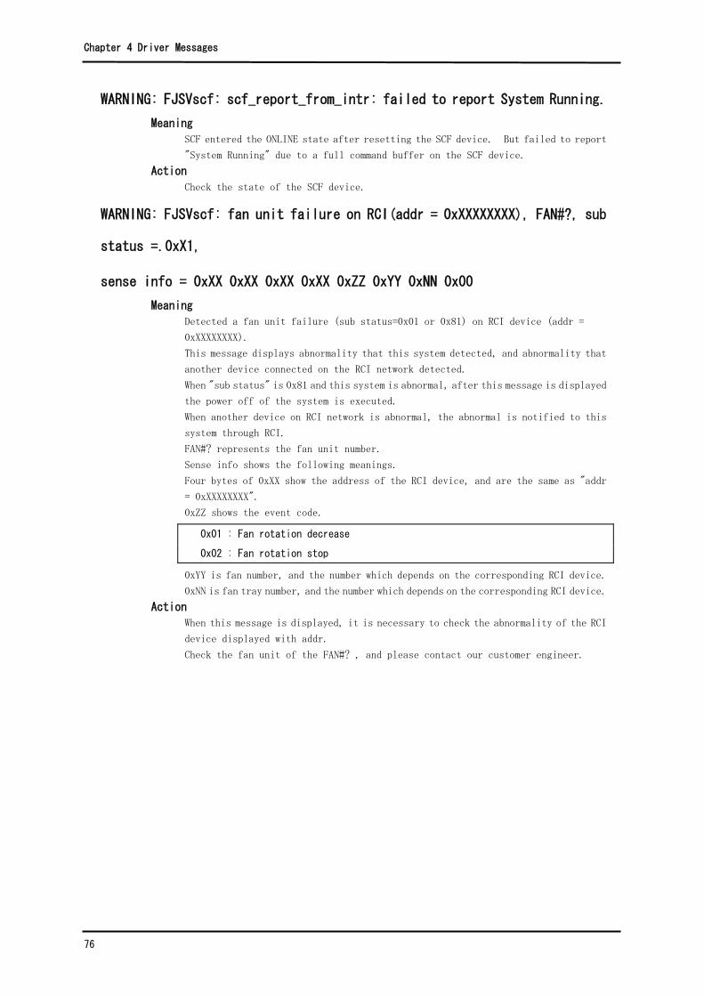
Chapter 4 Driver Messages
WARNING: FJSVscf: scf_report_from_intr: failed to report System Running.
Meaning
SCF entered the ONLINE state after resetting the SCF device. But failed to report
"System Running" due to a full command buffer on the SCF device.
Action
Check the state of the SCF device.
WARNING: FJSVscf: fan unit failure on RCI(addr = 0xXXXXXXXX), FAN#?, sub
status =.0xX1,
sense info = 0xXX 0xXX 0xXX 0xXX 0xZZ 0xYY 0xNN 0x00
Meaning
Detected a fan unit failure (sub status=0x01 or 0x81) on RCI device (addr =
0xXXXXXXXX).
This message displays abnormality that this system detected, and abnormality that
another device connected on the RCI network detected.
When "sub status" is 0x81 and this system is abnormal, after this message is displayed
the power off of the system is executed.
When another device on RCI network is abnormal, the abnormal is notified to this
system through RCI.
FAN#? represents the fan unit number.
Sense info shows the following meanings.
Four bytes of 0xXX show the address of the RCI device, and are the same as "addr
= 0xXXXXXXXX".
0xZZ shows the event code.
0x01 : Fan rotation decrease
0x02 : Fan rotation stop
0xYY is fan number, and the number which depends on the corresponding RCI device.
0xNN is fan tray number, and the number which depends on the corresponding RCI device.
Action
When this message is displayed, it is necessary to check the abnormality of the RCI
device displayed with addr.
Check the fan unit of the FAN#? , and please contact our customer engineer.
76
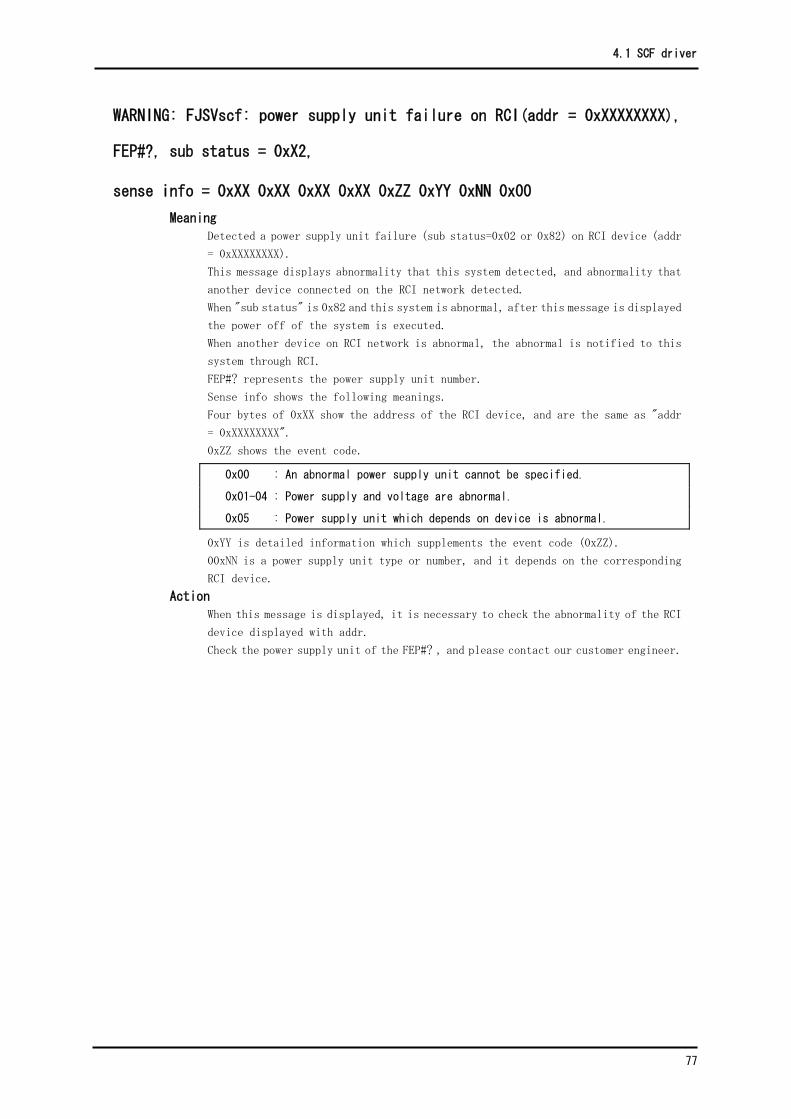
4.1 SCF driver
WARNING: FJSVscf: power supply unit failure on RCI(addr = 0xXXXXXXXX),
FEP#?, sub status = 0xX2,
sense info = 0xXX 0xXX 0xXX 0xXX 0xZZ 0xYY 0xNN 0x00
Meaning
Detected a power supply unit failure (sub status=0x02 or 0x82) on RCI device (addr
= 0xXXXXXXXX).
This message displays abnormality that this system detected, and abnormality that
another device connected on the RCI network detected.
When "sub status" is 0x82 and this system is abnormal, after this message is displayed
the power off of the system is executed.
When another device on RCI network is abnormal, the abnormal is notified to this
system through RCI.
FEP#? represents the power supply unit number.
Sense info shows the following meanings.
Four bytes of 0xXX show the address of the RCI device, and are the same as "addr
= 0xXXXXXXXX".
0xZZ shows the event code.
0x00 : An abnormal power supply unit cannot be specified.
0x01-04 : Power supply and voltage are abnormal.
0x05 : Power supply unit which depends on device is abnormal.
0xYY is detailed information which supplements the event code (0xZZ).
00xNN is a power supply unit type or number, and it depends on the corresponding
RCI device.
Action
When this message is displayed, it is necessary to check the abnormality of the RCI
device displayed with addr.
Check the power supply unit of the FEP#? , and please contact our customer engineer.
77

Chapter 4 Driver Messages
WARNING: FJSVscf: thermal alarm on RCI(addr = 0xXXXXXXXX), SENSOR#?, sub
status = 0xX6,
sense info = 0xXX 0xXX 0xXX 0xXX 0xZZ 0xYY 0x00 0x00
Meaning
Detected an abnormal temperature (sub status=0x06 or 0x86) on RCI device (addr =
0xXXXXXXXX).
This message displays abnormality that this system detected, and abnormality that
another device connected on the RCI network detected.
When "sub status" is 0x86 and this system is abnormal, after this message is displayed
the power off of the system is executed.
When another device on RCI network is abnormal, the abnormal is notified to this
system through RCI.
SENSOR#? represents the sensor number.
Sense info shows the following meanings.
Four bytes of 0xXX show the address of the RCI device, and are the same as "addr
= 0xXXXXXXXX".
0xZZ shows the event code.
0x01 : Ambient temperature low temperature warning
0x02 : Ambient temperature low temperature alarm
0x03 : Ambient temperature high temperature warning
0x04 : Ambient temperature high temperature alarm
0x05 : Unit/Processor low temperature warning, or sensor failure
0x06 : Unit/Processor low temperature alarm, or sensor failure
0x07 : Unit/Processor high temperature warning
0x08 : unit/processor high temperature alarm
0xYY is sensor number, and it depends on the corresponding RCI device.
Action
When this message is displayed, it is necessary to check the abnormality of the RCI
device displayed with addr.
Check the environment where the unit is set up.
Also make sure there is nothing wrong with the inside of the RCI device.
78

4.1 SCF driver
WARNING: FJSVscf: node error on RCI(addr = 0xXXXXXXXX), sub status = 0x08,
sense info = 0xXX 0xXX 0xXX 0xXX 0x00 0xZZ 0xYY 0x00
Meaning
Detected a node error (sub status=0x08) on RCI device (addr = 0xXXXXXXXX).
This message displays abnormality that this system detected, and abnormality that
another device connected on the RCI network detected.
When another device on RCI network is abnormal, the abnormal is notified to this
system through RCI.
Sense info shows the following meanings.
Four bytes of 0xXX show the address of the RCI device, and are the same as "addr
= 0xXXXXXXXX".
0xZZ shows the event code.
0x01 : The internal failure of RCI-I/O device
0x01-05 : SCF unit self-diagnosis error
0x90 : RCI network is abnormal (status check time-out)
0x91 : RCI address multiple error
0x92 : Host node is abnormal
0x93 : RCI device connection failure of unregistration
0x94 : SCF degeneracy
0xc0-ff : Hard error of RCI-I/O device
0xYY shows detailed information of RCI network abnormality (event code 0x90) or host
node abnormality (event code 0x92). Or, when the inside abnormality of RCI-I/O
device (event code 0x00), detailed information that depends on RCI-I/O device is
shown. Other event codes are irregular values, and it does not have the meaning.
Action
When this message is displayed, it is necessary to check the abnormality of the RCI
device displayed with addr.
Check RCI address is uniquely assigned to each RCI device, there are no RCI cable
problems, RCI device are turned power on, unconfigured RCI devices are not connected
or there are no internal failure in RCI devices. Please contact our customer
engineer.
79

Chapter 4 Driver Messages
NOTICE: FJSVscf: I/O node status sense from RCI(addr = 0xXXXXXXXX),sub
status = 0x62,
sense info = 0xXX 0xXX 0xXX 0xXX 0xZZ 0xYY 0xYY 0xYY
Meaning
Detected a sensed information of I/O node status (sub status=0x062) from RCI device
(addr = 0xXXXXXXXX).
This message displays the change of the state of another device connected on the
RCI network.
Sense info shows the following meanings.
Four bytes of 0xXX show the address of the RCI device, and are the same as "addr
= 0xXXXXXXXX".
0xZZ shows the event code.
0x01 : RCI-I/O device connection or power supply reentry
0x02 : RCI-I/O device disconnect
0xYY is type or number of RCI-I/O device, and it depends on corresponding RCI-I/O
device.
Action
It is not necessary.
When this message is frequently displayed, it is necessary to investigate the RCI
device, and please contact our customer engineer.
WARNING: FJSVscf: mount error on RCI(addr = 0xXXXXXXXX), sub status = 0xX9,
sense info = 0xXX 0xXX 0xXX 0xXX 0xZZ 0xYY 0xYY 0x00
Meaning
Detected a mount error (sub status=0x09 or 0x89) on RCI device (addr = 0xXXXXXXXX).
This message displays abnormality that this system detected, and abnormality that
another device connected on the RCI network detected.
When another device on RCI network is abnormal, the abnormal is notified to this
system through RCI.
Sense info shows the following meanings.
Four bytes of 0xXX show the address of the RCI device, and are the same as "addr
= 0xXXXXXXXX".
0xZZ shows the event code.
0x01 : mount error (a lot of mounting)
0x02 : mount error (few mounting)
0x02 : mount position is abnormal
0xYY is detailed information which supplements the event code (0xZZ).
Action
When this message is displayed, it is necessary to check the abnormality of the RCI
device displayed with addr.
Check the corresponding RCI device, and please contact our customer engineer.
80

4.1 SCF driver
WARNING: FJSVscf: unexpected sense from RCI(addr = 0xXXXXXXXX) was detected.
sub status = 0xYY,
sense info = 0xXX 0xXX 0xXX 0xXX 0xZZ 0xZZ 0xZZ 0xZZ
Meaning
Detected an unexpected sense information from RCI device (addr = 0xXXXXXXXX).
sub status = 0xYY shows the device information command.
0x4X : Device status notification
0x70 : Device attribute display
0x71 : Device status display
When sense information is notified according to the timing unexpected from another
device connected with the RCI network, this message is displayed.
When another device on RCI network is abnormal, the abnormal is notified to this
system through RCI.
Sense info shows the following meanings.
Four bytes of 0xXX show the address of the RCI device, and are the same as "addr
= 0xXXXXXXXX".
0xZZ shows the notified sense information, and depends on the corresponding RCI
device.
Action
When this message is displayed, it is necessary to check the abnormality of the RCI
device displayed with addr.
Check the corresponding RCI device, and please contact our customer engineer.
WARNING: FJSVscf: device sense from RCI(addr = 0xXXXXXXXX), sub status =
0xYY,
sense info = 0xXX 0xXX 0xXX 0xXX 0xXZZ 0xZZ 0xZZ 0xZZ
Meaning
Detected a sensed information form RCI device (addr = 0xXXXXXXXX) that SCF driver
does not support or undefined.
This message displays abnormality that this system detected, and abnormality that
another device connected on the RCI network detected.
When another device on RCI network is abnormal, the abnormal is notified to this
system through RCI.
0xYY shows the event code notified the SCF driver.
Sense info shows the following meanings.
Four bytes of 0xXX show the address of the RCI device, and are the same as "addr
= 0xXXXXXXXX".
0xZZ shows notified sense information, and is an irregular value.
Action
When this message is displayed, it is necessary to check the abnormality of the RCI
device displayed with addr.
Check the corresponding RCI device, and please contact our customer engineer.
When RCI device is this system, check whether to operate about "Machine
Administration".
81

Chapter 4 Driver Messages
WARNING: FJSVscf: AC power down was detected on RCI(addr = 0xXXXXXXXX),
sub status = 0xX7,
sense info = 0xXX 0xXX 0xXX 0xXX 0xZZ 0xYY 0xYY 0xYY
Meaning
Detected a AC power down (sub status=0x07 or 0x87) on RCI device. (addr = 0xXXXXXXXX)
This message displays abnormality that another device connected on the RCI network
detected.
When another device on RCI network is abnormal, the abnormal is notified to this
system through RCI.
Sense info shows the following meanings.
Four bytes of 0xXX show the address of the RCI device, and are the same as "addr
= 0xXXXXXXXX".
0xZZ shows the event code.
0x01 : Power failure occurred
0xZZ shows the notified sense information, and depends on the corresponding RCI
device.
Action
When this message is displayed, it is necessary to check the abnormality of the RCI
device displayed with addr.
Check the corresponding RCI device, and please contact our customer engineer.
WARNING: FJSVscf: power supply unit failure on RCI(addr = 0xXXXXXXXX), BE#?,
sub status = 0xX2,
sense info = 0xXX 0xXX 0xXX 0xXX 0xZZ 0xYY 0xNN 0x00
Meaning
Detected a BE power supply unit failure (sub status=0x02 or 0x82) on RCI device (addr
= 0xXXXXXXXX).
This message displays abnormality that this system detected, and abnormality that
another device connected on the RCI network detected.
When "sub status" is 0x82 and this system is abnormal, after this message is displayed
the power off of the system is executed.
When another device on RCI network is abnormal, the abnormal is notified to this
system through RCI.
BE#? represents the BE power supply unit number.
Sense info shows the following meanings.
Four bytes of 0xXX show the address of the RCI device, and are the same as "addr
= 0xXXXXXXXX".
0xZZ shows the event code.
0x05 : BE power supply unit which depends on device is abnormal.
0xYY is detailed information which supplements the event code (0xZZ).
0xNN is a BE power supply unit type or number, and it depends on the corresponding
RCI device.
Action
When this message is displayed, it is necessary to check the abnormality of the RCI
device displayed with addr.
Check the power supply unit of the BE#? , and please contact our customer engineer.
82
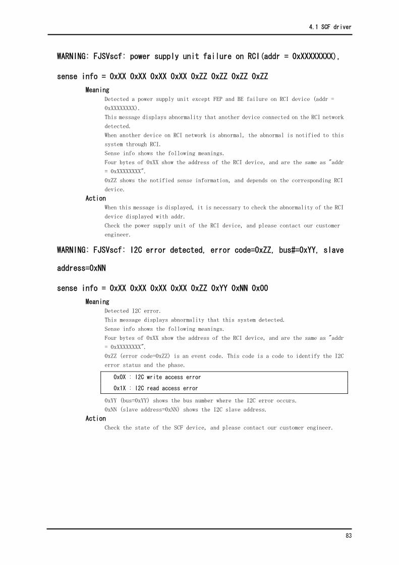
4.1 SCF driver
WARNING: FJSVscf: power supply unit failure on RCI(addr = 0xXXXXXXXX),
sense info = 0xXX 0xXX 0xXX 0xXX 0xZZ 0xZZ 0xZZ 0xZZ
Meaning
Detected a power supply unit except FEP and BE failure on RCI device (addr =
0xXXXXXXXX).
This message displays abnormality that another device connected on the RCI network
detected.
When another device on RCI network is abnormal, the abnormal is notified to this
system through RCI.
Sense info shows the following meanings.
Four bytes of 0xXX show the address of the RCI device, and are the same as "addr
= 0xXXXXXXXX".
0xZZ shows the notified sense information, and depends on the corresponding RCI
device.
Action
When this message is displayed, it is necessary to check the abnormality of the RCI
device displayed with addr.
Check the power supply unit of the RCI device, and please contact our customer
engineer.
WARNING: FJSVscf: I2C error detected, error code=0xZZ, bus#=0xYY, slave
address=0xNN
sense info = 0xXX 0xXX 0xXX 0xXX 0xZZ 0xYY 0xNN 0x00
Meaning
Detected I2C error.
This message displays abnormality that this system detected.
Sense info shows the following meanings.
Four bytes of 0xXX show the address of the RCI device, and are the same as "addr
= 0xXXXXXXXX".
0xZZ (error code=0xZZ) is an event code. This code is a code to identify the I2C
error status and the phase.
0x0X : I2C write access error
0x1X : I2C read access error
0xYY (bus=0xYY) shows the bus number where the I2C error occurs.
0xNN (slave address=0xNN) shows the I2C slave address.
Action
Check the state of the SCF device, and please contact our customer engineer.
83

Chapter 4 Driver Messages
4.1.3 For PRIMEPOWER 250/450
WARNING: FJSVscf: _init: ddi_soft_state_init failed.
Meaning
Failed to incorporate the SCF driver into the system due to the abnormal termination
of ddi_soft_state_init (9F).
Action
Allocate memory since there might not be enough kernel resources.
WARNING: FJSVscf: _init: mod_install failed.
Meaning
Failed to incorporate the SCF driver into the system due to the abnormal termination
of mod_install (9F) (incorporates the driver into the system).
Action
Allocate memory since there might not be enough kernel resources.
WARNING: FJSVscf: scf_probe: ddi_soft_state_zalloc failed.
Meaning
Failed to incorporate the SCF driver into the system due to the abnormal termination
of ddi_soft_state_zalloc (9F) (allocates an area for the driver).
Action
Allocate memory since there might not be enough kernel resources.
WARNING: FJSVscf: scf_probe: ddi_get_soft_state failed.
Meaning
Failed to incorporate the SCF driver into the system due to the abnormal termination
of ddi_get_soft_state (9F) (gets an area for the driver).
Action
Allocate memory since there might not be enough kernel resources.
WARNING: /pci@#,#/#@#/FJSV,scfc@#,#(scfc#),scf_probe: ddi_dev_nregs
failed.
Meaning
The register information in the SCF device is incorrect.
Action
Check the state of the system board.
WARNING: FJSVscf: scf_attach: ddi_get_iblock_cookie failed.
Meaning
Failed to incorporate the SCF driver into the system due to the abnormal termination
of ddi_get_iblock_cookie (9F) (allocates resources for interrupt processing).
Action
Allocate memory since there might not be enough kernel resources.
84
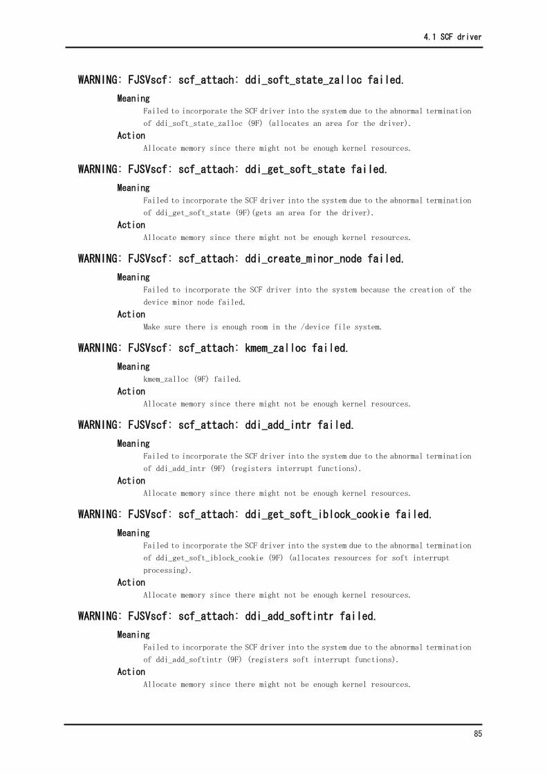
4.1 SCF driver
WARNING: FJSVscf: scf_attach: ddi_soft_state_zalloc failed.
Meaning
Failed to incorporate the SCF driver into the system due to the abnormal termination
of ddi_soft_state_zalloc (9F) (allocates an area for the driver).
Action
Allocate memory since there might not be enough kernel resources.
WARNING: FJSVscf: scf_attach: ddi_get_soft_state failed.
Meaning
Failed to incorporate the SCF driver into the system due to the abnormal termination
of ddi_get_soft_state (9F)(gets an area for the driver).
Action
Allocate memory since there might not be enough kernel resources.
WARNING: FJSVscf: scf_attach: ddi_create_minor_node failed.
Meaning
Failed to incorporate the SCF driver into the system because the creation of the
device minor node failed.
Action
Make sure there is enough room in the /device file system.
WARNING: FJSVscf: scf_attach: kmem_zalloc failed.
Meaning
kmem_zalloc (9F) failed.
Action
Allocate memory since there might not be enough kernel resources.
WARNING: FJSVscf: scf_attach: ddi_add_intr failed.
Meaning
Failed to incorporate the SCF driver into the system due to the abnormal termination
of ddi_add_intr (9F) (registers interrupt functions).
Action
Allocate memory since there might not be enough kernel resources.
WARNING: FJSVscf: scf_attach: ddi_get_soft_iblock_cookie failed.
Meaning
Failed to incorporate the SCF driver into the system due to the abnormal termination
of ddi_get_soft_iblock_cookie (9F) (allocates resources for soft interrupt
processing).
Action
Allocate memory since there might not be enough kernel resources.
WARNING: FJSVscf: scf_attach: ddi_add_softintr failed.
Meaning
Failed to incorporate the SCF driver into the system due to the abnormal termination
of ddi_add_softintr (9F) (registers soft interrupt functions).
Action
Allocate memory since there might not be enough kernel resources.
85

Chapter 4 Driver Messages
WARNING: FJSVscf: scf_detach: ddi_get_soft_state failed.
Meaning
Could not detach the SCF driver due to the abnormal termination of ddi_get_soft_state
(9F) (gets an area for the driver).
Action
Allocate memory since there might not be enough kernel resources.
WARNING: /pci@#,#/#@#/FJSV,scfc@#,#(scfc#), IOCHRDY interrupt occurred.
Meaning
IOCHRDY timeout (Ebus2 timeout) interrupt occurred.
Action
Check the state of the system board and SCF device.
WARNING: /pci@#,#/#@#/FJSV,scfc@#,#(scfc#), DMA host bus error.
Meaning
Host bus error interrupt occurred to the Ebus2 DMA.
Action
Check the state of the system board and SCF device.
WARNING: /pci@#,#/#@#/FJSV,scfc@#,#(scfc#), SCF command (0xXXXX) receive
data sum check error
Meaning
Detected Sum check error to the receive data of SCF command (0xXXXX).
Action
Check the state of the system board and SCF device.
86

4.1 SCF driver
WARNING: /pci@#,#/#@#/FJSV,scfc@#,#(scfc#), SCF command (0xXXXX) error.
Status register = 0xYYYY
Meaning
SCF command (0xXXXX) terminated abnormally. 0xYYYY represents the SCF-2 Status
register.
Status register has the following meaning by the value of the least significant four
bits.
0xX1XX : Sending a command to SCF device was repeated five times due to RCI
BUFFER-FULL on the SCF device. But they were not processed normally.
0xX2XX : Sending a command to SCF device was repeated fifteen times due to RCI device
BUSY on the SCF device. But they were not processed normally.
0xX3XX : Sending a command to SCF device due to the error on the command Interface
with the SCF device.
0xX8XX : The command and sub-command that it was sent to the SCF device was not
supported.
0xX9XX : The command that it was sent to the SCF device failed with the parameter
error.
0xXBXX : The device specified with the address for the command that it was sent to
the SCF device does not exist on the RCI network, or RCI is inactive.
0xXCXX : The command that it was sent to the SCF device failed with the access error
to hardware.
0xXDXX : The command that it was sent to the SCF device failed with the violation
of the execution condition
0xXEXX : The command that it was sent to the SCF device failed with the BUFFER-FULL.
Action
Check the state of the SCF device.
WARNING: /pci@#,#/#@#/FJSV,scfc@#,#(scfc#),XXX register parity error.
Status register = 0xYYYY
Meaning
Parity error interrupt occurred to the XXX register read. 0xYYYY represents the
XXX register.
XXX is register name.
SCF command/status
SCF interrupt status
SCF interrupt mask
SCF mode-sw
SCF length
Action
Check the state of the system board and SCF device.
87

Chapter 4 Driver Messages
WARNING: FJSVscf: SCF HALT was detected.
Meaning
All SCF devices stopped. After this message was displayed, access to SCF device will
be failed.
Action
Follow the instruction of the message displayed before this message.
WARNING: FJSVscf: /pci@#,#/#@#/FJSV,scfc@#,#(scfc#), SCF command (0xXXXX)
timeout
Meaning
The SCF command (0xXXXX) could not complete a command within the prescribed time.
Action
Check the state of the system board and SCF device.
WARNING: FJSVscf: scf_intr: Unexpected POFF interrupt occurred
Meaning
A POWER switch interrupt occurred while the mode switch on the operator panel was
set to LOCK.
Action
Check the state of the mode switch.
WARNING: FJSVscf: AC power down was detected. UPS is activated. RCI(addr
= 0xXXXXXXXX)
Meaning
Power of RCI device (addr=0xXXXXXXXX) is now being supplied by the UPS due to a power
down.
Action
Check the state of the power supply of RCI device.
WARNING: FJSVscf: AC power down was detected. UPS is activated. AAA#?
Meaning
Power is now being supplied by the UPS due to a power down of power supply unit.
AAA represents the power supply unit type. #? represents the unit number.
AAA#? will be displayed only if a unit failure occurred on the following units.
PSU
Action
Check the state of the power supply of power supply unit displayed in AAA#? .
WARNING: FJSVscf: Input power down was detected. UPS is activated. RCI(addr
= 0xXXXXXXXX)
Meaning
Power of RCI device (addr=0xXXXXXXXX) is now being supplied by the UPS due to a power
down.
Action
Check the state of the power supply of RCI device.
88
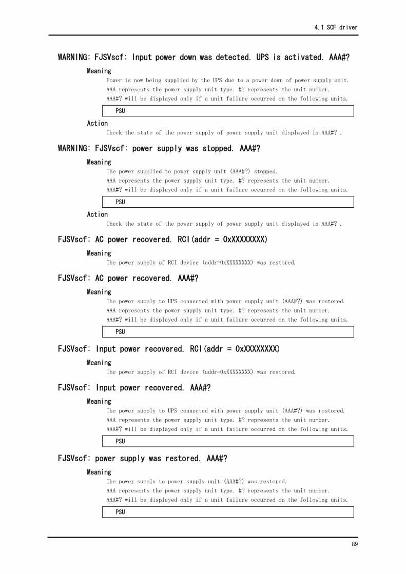
4.1 SCF driver
WARNING: FJSVscf: Input power down was detected. UPS is activated. AAA#?
Meaning
Power is now being supplied by the UPS due to a power down of power supply unit.
AAA represents the power supply unit type. #? represents the unit number.
AAA#? will be displayed only if a unit failure occurred on the following units.
PSU
Action
Check the state of the power supply of power supply unit displayed in AAA#? .
WARNING: FJSVscf: power supply was stopped. AAA#?
Meaning
The power supplied to power supply unit (AAA#?) stopped.
AAA represents the power supply unit type. #? represents the unit number.
AAA#? will be displayed only if a unit failure occurred on the following units.
PSU
Action
Check the state of the power supply of power supply unit displayed in AAA#? .
FJSVscf: AC power recovered. RCI(addr = 0xXXXXXXXX)
Meaning
The power supply of RCI device (addr=0xXXXXXXXX) was restored.
FJSVscf: AC power recovered. AAA#?
Meaning
The power supply to UPS connected with power supply unit (AAA#?) was restored.
AAA represents the power supply unit type. #? represents the unit number.
AAA#? will be displayed only if a unit failure occurred on the following units.
PSU
FJSVscf: Input power recovered. RCI(addr = 0xXXXXXXXX)
Meaning
The power supply of RCI device (addr=0xXXXXXXXX) was restored.
FJSVscf: Input power recovered. AAA#?
Meaning
The power supply to UPS connected with power supply unit (AAA#?) was restored.
AAA represents the power supply unit type. #? represents the unit number.
AAA#? will be displayed only if a unit failure occurred on the following units.
PSU
FJSVscf: power supply was restored. AAA#?
Meaning
The power supply to power supply unit (AAA#?) was restored.
AAA represents the power supply unit type. #? represents the unit number.
AAA#? will be displayed only if a unit failure occurred on the following units.
PSU
89
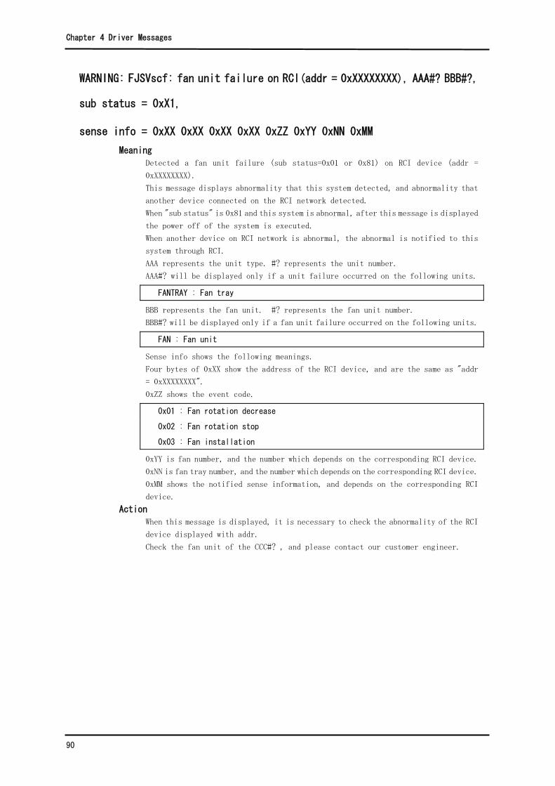
Chapter 4 Driver Messages
WARNING: FJSVscf: fan unit failure on RCI(addr = 0xXXXXXXXX), AAA#? BBB#?,
sub status = 0xX1,
sense info = 0xXX 0xXX 0xXX 0xXX 0xZZ 0xYY 0xNN 0xMM
Meaning
Detected a fan unit failure (sub status=0x01 or 0x81) on RCI device (addr =
0xXXXXXXXX).
This message displays abnormality that this system detected, and abnormality that
another device connected on the RCI network detected.
When "sub status" is 0x81 and this system is abnormal, after this message is displayed
the power off of the system is executed.
When another device on RCI network is abnormal, the abnormal is notified to this
system through RCI.
AAA represents the unit type. #? represents the unit number.
AAA#? will be displayed only if a unit failure occurred on the following units.
FANTRAY : Fan tray
BBB represents the fan unit. #? represents the fan unit number.
BBB#? will be displayed only if a fan unit failure occurred on the following units.
FAN : Fan unit
Sense info shows the following meanings.
Four bytes of 0xXX show the address of the RCI device, and are the same as "addr
= 0xXXXXXXXX".
0xZZ shows the event code.
0x01 : Fan rotation decrease
0x02 : Fan rotation stop
0x03 : Fan installation
0xYY is fan number, and the number which depends on the corresponding RCI device.
0xNN is fan tray number, and the number which depends on the corresponding RCI device.
0xMM shows the notified sense information, and depends on the corresponding RCI
device.
Action
When this message is displayed, it is necessary to check the abnormality of the RCI
device displayed with addr.
Check the fan unit of the CCC#? , and please contact our customer engineer.
90
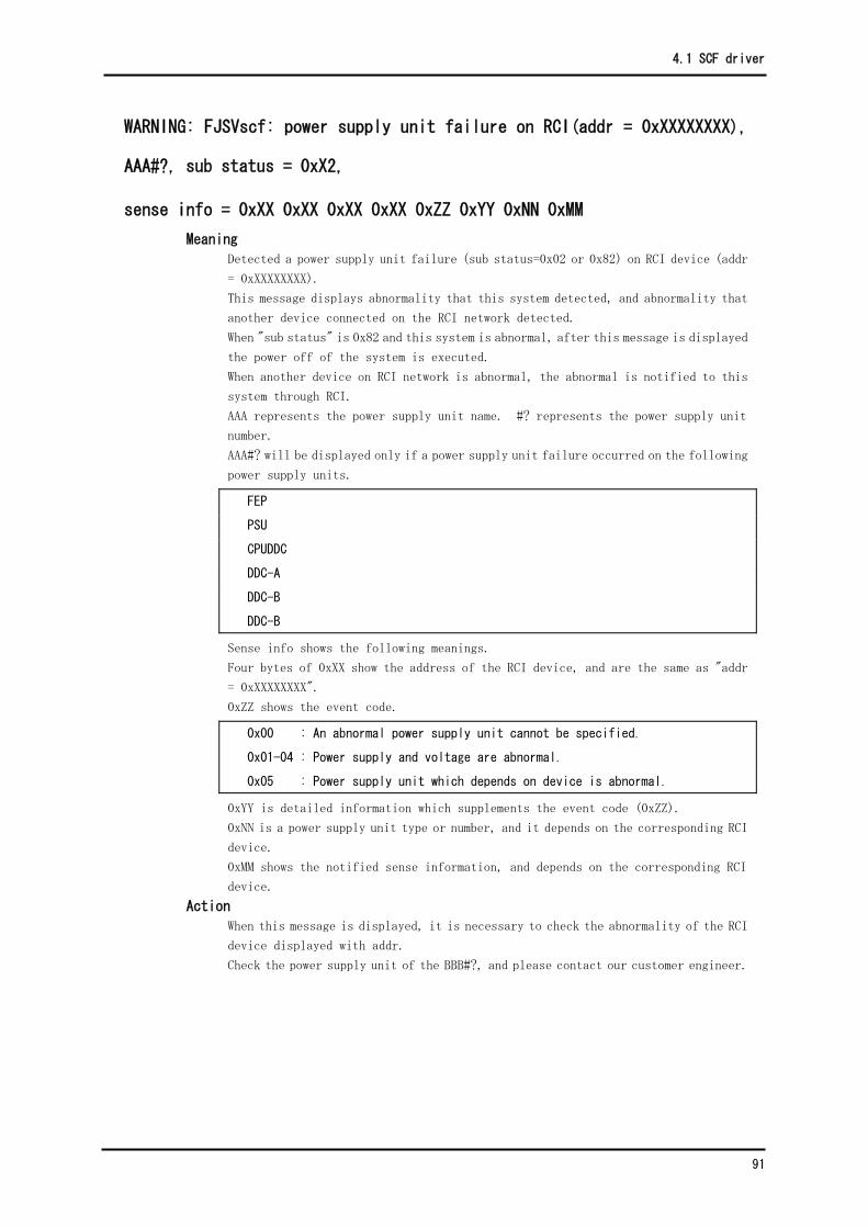
4.1 SCF driver
WARNING: FJSVscf: power supply unit failure on RCI(addr = 0xXXXXXXXX),
AAA#?, sub status = 0xX2,
sense info = 0xXX 0xXX 0xXX 0xXX 0xZZ 0xYY 0xNN 0xMM
Meaning
Detected a power supply unit failure (sub status=0x02 or 0x82) on RCI device (addr
= 0xXXXXXXXX).
This message displays abnormality that this system detected, and abnormality that
another device connected on the RCI network detected.
When "sub status" is 0x82 and this system is abnormal, after this message is displayed
the power off of the system is executed.
When another device on RCI network is abnormal, the abnormal is notified to this
system through RCI.
AAA represents the power supply unit name. #? represents the power supply unit
number.
AAA#? will be displayed only if a power supply unit failure occurred on the following
power supply units.
FEP
PSU
CPUDDC
DDC-A
DDC-B
DDC-B
Sense info shows the following meanings.
Four bytes of 0xXX show the address of the RCI device, and are the same as "addr
= 0xXXXXXXXX".
0xZZ shows the event code.
0x00 : An abnormal power supply unit cannot be specified.
0x01-04 : Power supply and voltage are abnormal.
0x05 : Power supply unit which depends on device is abnormal.
0xYY is detailed information which supplements the event code (0xZZ).
0xNN is a power supply unit type or number, and it depends on the corresponding RCI
device.
0xMM shows the notified sense information, and depends on the corresponding RCI
device.
Action
When this message is displayed, it is necessary to check the abnormality of the RCI
device displayed with addr.
Check the power supply unit of the BBB#?, and please contact our customer engineer.
91
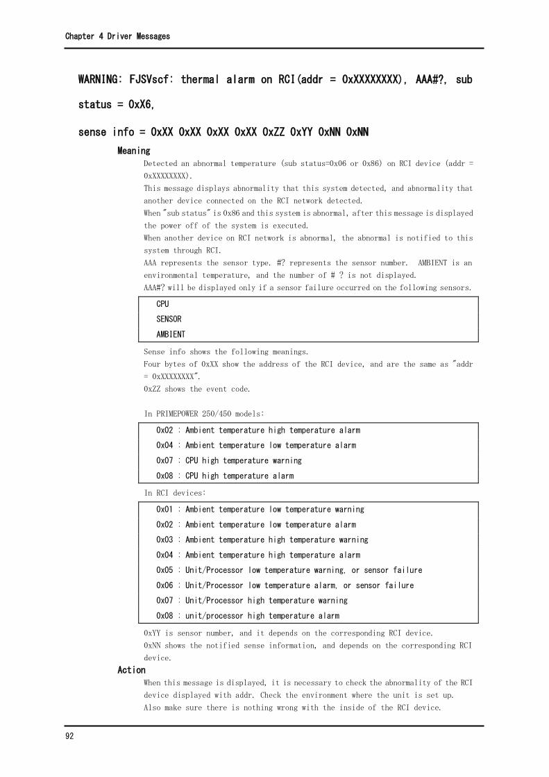
Chapter 4 Driver Messages
92
WARNING: FJSVscf: thermal alarm on RCI(addr = 0xXXXXXXXX), AAA#?, sub
status = 0xX6,
sense info = 0xXX 0xXX 0xXX 0xXX 0xZZ 0xYY 0xNN 0xNN
Meaning
Detected an abnormal temperature (sub status=0x06 or 0x86) on RCI device (addr =
0xXXXXXXXX).
This message displays abnormality that this system detected, and abnormality that
another device connected on the RCI network detected.
When "sub status" is 0x86 and this system is abnormal, after this message is displayed
the power off of the system is executed.
When another device on RCI network is abnormal, the abnormal is notified to this
system through RCI.
AAA represents the sensor type. #? represents the sensor number. AMBIENT is an
environmental temperature, and the number of # ? is not displayed.
AAA#? will be displayed only if a sensor failure occurred on the following sensors.
CPU
SENSOR
AMBIENT
Sense info shows the following meanings.
Four bytes of 0xXX show the address of the RCI device, and are the same as "addr
= 0xXXXXXXXX".
0xZZ shows the event code.
In PRIMEPOWER 250/450 models:
0x02 : Ambient temperature high temperature alarm
0x04 : Ambient temperature low temperature alarm
0x07 : CPU high temperature warning
0x08 : CPU high temperature alarm
In RCI devices:
0x01 : Ambient temperature low temperature warning
0x02 : Ambient temperature low temperature alarm
0x03 : Ambient temperature high temperature warning
0x04 : Ambient temperature high temperature alarm
0x05 : Unit/Processor low temperature warning, or sensor failure
0x06 : Unit/Processor low temperature alarm, or sensor failure
0x07 : Unit/Processor high temperature warning
0x08 : unit/processor high temperature alarm
0xYY is sensor number, and it depends on the corresponding RCI device.
0xNN shows the notified sense information, and depends on the corresponding RCI
device.
Action
When this message is displayed, it is necessary to check the abnormality of the RCI
device displayed with addr. Check the environment where the unit is set up.
Also make sure there is nothing wrong with the inside of the RCI device.

4.1 SCF driver
WARNING: FJSVscf: node error on RCI(addr = 0xXXXXXXXX), sub status = 0x08,
sense info = 0xXX 0xXX 0xXX 0xXX 0x00 0xZZ 0xYY 0xXX
Meaning
Detected a node error (sub status=0x08) on RCI device (addr = 0xXXXXXXXX).
This message displays abnormality that this system detected, and abnormality that
another device connected on the RCI network detected.
When another device on RCI network is abnormal, the abnormal is notified to this
system through RCI.
Sense info shows the following meanings.
Four bytes of 0xXX show the address of the RCI device, and are the same as "addr
= 0xXXXXXXXX".
0xZZ shows the event code.
0x01 : The internal failure of RCI-I/O device
0x01-05 : SCF unit self-diagnosis error
0x90 : RCI network is abnormal (status check time-out)
0x91 : RCI address multiple error
0x92 : Host node is abnormal
0x93 : RCI device connection failure of unregistration
0x94 : SCF degeneracy
0x95 : Sensor failure of Host node
0xc0-ff : Hard error of RCI-I/O device
0xYY shows detailed information of RCI network abnormality(event code 0x90) or host
node abnormality(event code 0x92). Or, when the inside abnormality of RCI-I/O
device (event code 0x00), detailed information that depends on RCI-I/O device is
shown. Other event codes are irregular values, and it does not have the meaning.
Action
When this message is displayed, it is necessary to check the abnormality of the RCI
device displayed with addr.
Check RCI address is uniquely assigned to each RCI device, there are no RCI cable
problems, RCI device are turned power on, unconfigured RCI devices are not connected
or there are no internal failure in RCI devices. Please contact our customer
engineer.
panic[cpuX]/thread = 0xXXXXXXXX: FJSVscf: panic request from RCI(addr =
0xXXXXXXXX)
Meaning
The RCI device that has RCI address of 0xXXX requested the system panic.
Action
This message shows the state.
However, at the cluster environment etc. , another node (RCI address 0xXXXXXXXX)
which detected abnormality issues the panic instruction to this node via RCI. And,
when OS panic is executed, this node outputs this message.
Please investigate this node from information on another node (RCI address
0xXXXXXXXX).
93
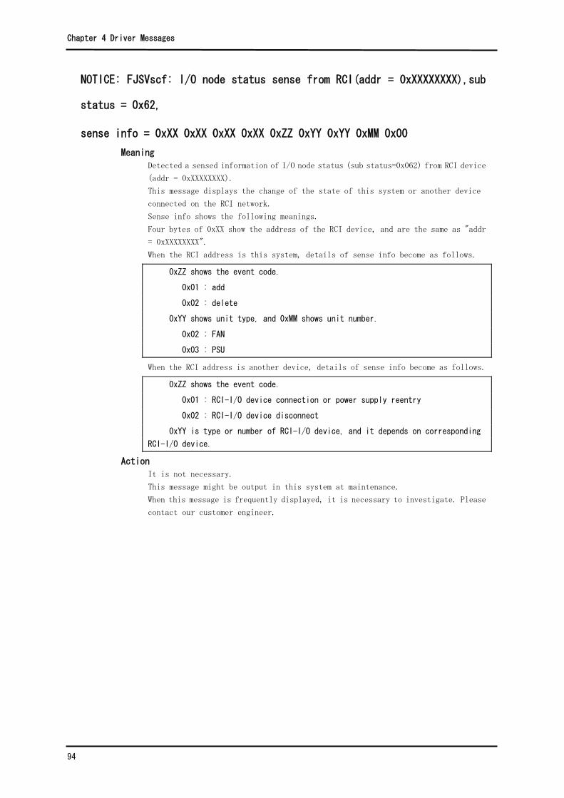
Chapter 4 Driver Messages
NOTICE: FJSVscf: I/O node status sense from RCI(addr = 0xXXXXXXXX),sub
status = 0x62,
sense info = 0xXX 0xXX 0xXX 0xXX 0xZZ 0xYY 0xYY 0xMM 0x00
Meaning
Detected a sensed information of I/O node status (sub status=0x062) from RCI device
(addr = 0xXXXXXXXX).
This message displays the change of the state of this system or another device
connected on the RCI network.
Sense info shows the following meanings.
Four bytes of 0xXX show the address of the RCI device, and are the same as "addr
= 0xXXXXXXXX".
When the RCI address is this system, details of sense info become as follows.
0xZZ shows the event code.
0x01 : add
0x02 : delete
0xYY shows unit type, and 0xMM shows unit number.
0x02 : FAN
0x03 : PSU
When the RCI address is another device, details of sense info become as follows.
0xZZ shows the event code.
0x01 : RCI-I/O device connection or power supply reentry
0x02 : RCI-I/O device disconnect
0xYY is type or number of RCI-I/O device, and it depends on corresponding
RCI-I/O device.
Action
It is not necessary.
This message might be output in this system at maintenance.
When this message is frequently displayed, it is necessary to investigate. Please
contact our customer engineer.
94
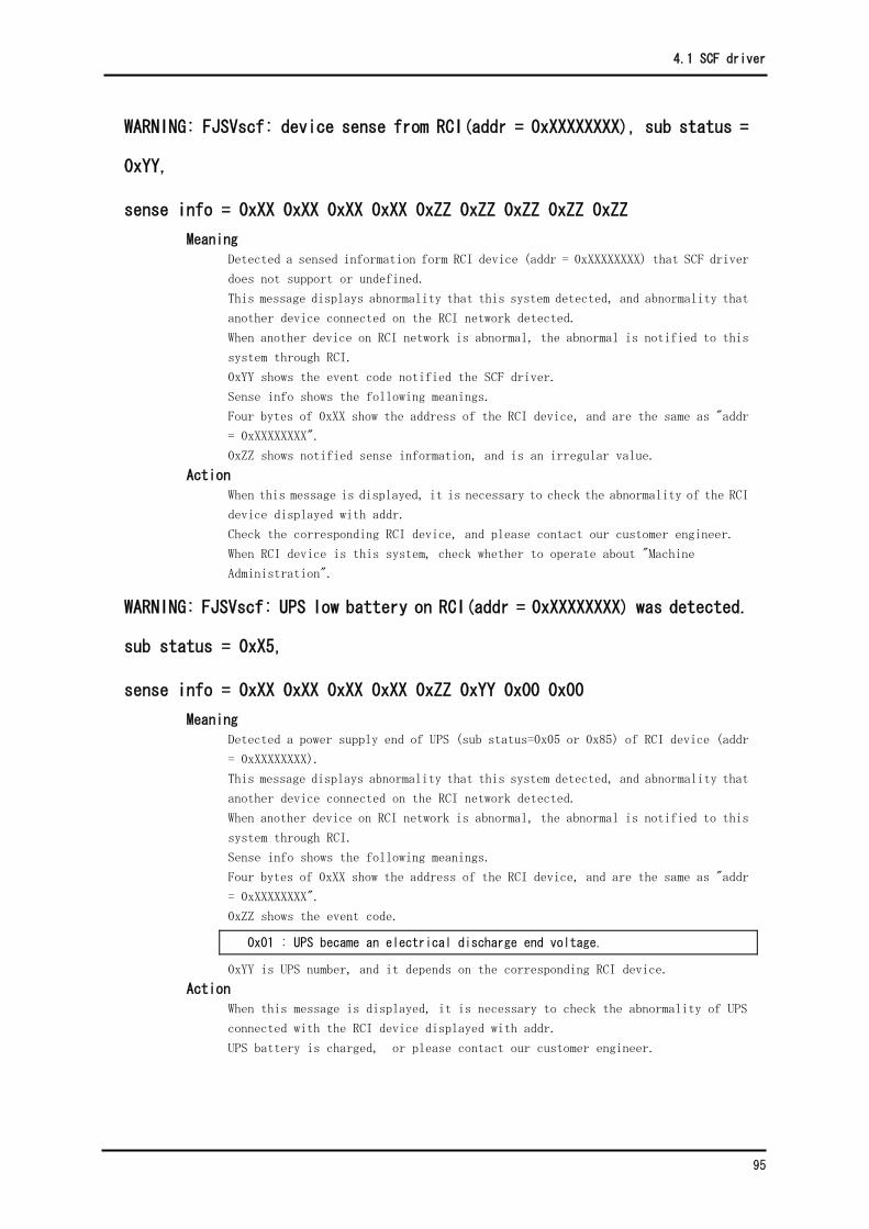
4.1 SCF driver
WARNING: FJSVscf: device sense from RCI(addr = 0xXXXXXXXX), sub status =
0xYY,
sense info = 0xXX 0xXX 0xXX 0xXX 0xZZ 0xZZ 0xZZ 0xZZ 0xZZ
Meaning
Detected a sensed information form RCI device (addr = 0xXXXXXXXX) that SCF driver
does not support or undefined.
This message displays abnormality that this system detected, and abnormality that
another device connected on the RCI network detected.
When another device on RCI network is abnormal, the abnormal is notified to this
system through RCI.
0xYY shows the event code notified the SCF driver.
Sense info shows the following meanings.
Four bytes of 0xXX show the address of the RCI device, and are the same as "addr
= 0xXXXXXXXX".
0xZZ shows notified sense information, and is an irregular value.
Action
When this message is displayed, it is necessary to check the abnormality of the RCI
device displayed with addr.
Check the corresponding RCI device, and please contact our customer engineer.
When RCI device is this system, check whether to operate about "Machine
Administration".
WARNING: FJSVscf: UPS low battery on RCI(addr = 0xXXXXXXXX) was detected.
sub status = 0xX5,
sense info = 0xXX 0xXX 0xXX 0xXX 0xZZ 0xYY 0x00 0x00
Meaning
Detected a power supply end of UPS (sub status=0x05 or 0x85) of RCI device (addr
= 0xXXXXXXXX).
This message displays abnormality that this system detected, and abnormality that
another device connected on the RCI network detected.
When another device on RCI network is abnormal, the abnormal is notified to this
system through RCI.
Sense info shows the following meanings.
Four bytes of 0xXX show the address of the RCI device, and are the same as "addr
= 0xXXXXXXXX".
0xZZ shows the event code.
0x01 : UPS became an electrical discharge end voltage.
0xYY is UPS number, and it depends on the corresponding RCI device.
Action
When this message is displayed, it is necessary to check the abnormality of UPS
connected with the RCI device displayed with addr.
UPS battery is charged, or please contact our customer engineer.
95
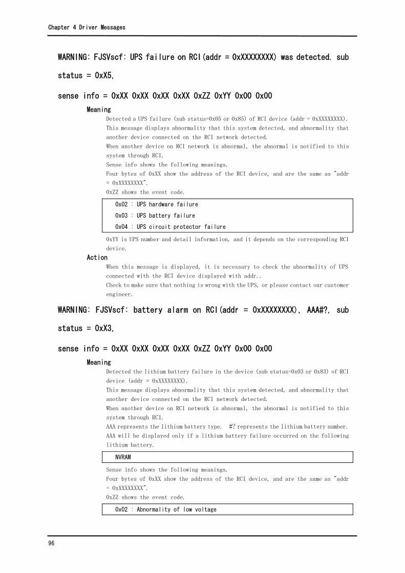
Chapter 4 Driver Messages
WARNING: FJSVscf: UPS failure on RCI(addr = 0xXXXXXXXX) was detected. sub
status = 0xX5,
sense info = 0xXX 0xXX 0xXX 0xXX 0xZZ 0xYY 0x00 0x00
Meaning
Detected a UPS failure (sub status=0x05 or 0x85) of RCI device (addr = 0xXXXXXXXX).
This message displays abnormality that this system detected, and abnormality that
another device connected on the RCI network detected.
When another device on RCI network is abnormal, the abnormal is notified to this
system through RCI.
Sense info shows the following meanings.
Four bytes of 0xXX show the address of the RCI device, and are the same as "addr
= 0xXXXXXXXX".
0xZZ shows the event code.
0x02 : UPS hardware failure
0x03 : UPS battery failure
0x04 : UPS circuit protector failure
0xYY is UPS number and detail information, and it depends on the corresponding RCI
device.
Action
When this message is displayed, it is necessary to check the abnormality of UPS
connected with the RCI device displayed with addr..
Check to make sure that nothing is wrong with the UPS, or please contact our customer
engineer.
WARNING: FJSVscf: battery alarm on RCI(addr = 0xXXXXXXXX), AAA#?, sub
status = 0xX3,
sense info = 0xXX 0xXX 0xXX 0xXX 0xZZ 0xYY 0x00 0x00
Meaning
Detected the lithium battery failure in the device (sub status=0x03 or 0x83) of RCI
device (addr = 0xXXXXXXXX).
This message displays abnormality that this system detected, and abnormality that
another device connected on the RCI network detected.
When another device on RCI network is abnormal, the abnormal is notified to this
system through RCI.
AAA represents the lithium battery type. #? represents the lithium battery number.
AAA will be displayed only if a lithium battery failure occurred on the following
lithium battery.
NVRAM
Sense info shows the following meanings.
Four bytes of 0xXX show the address of the RCI device, and are the same as "addr
= 0xXXXXXXXX".
0xZZ shows the event code.
0x02 : Abnormality of low voltage
96
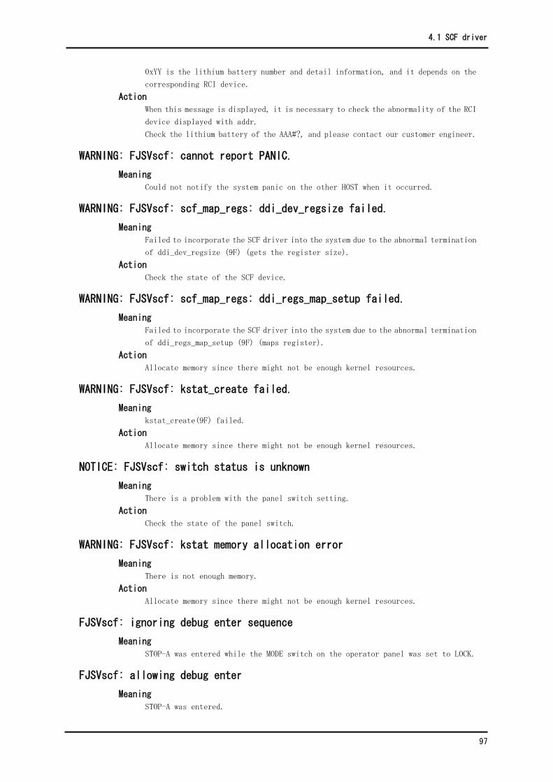
4.1 SCF driver
0xYY is the lithium battery number and detail information, and it depends on the
corresponding RCI device.
Action
When this message is displayed, it is necessary to check the abnormality of the RCI
device displayed with addr.
Check the lithium battery of the AAA#?, and please contact our customer engineer.
WARNING: FJSVscf: cannot report PANIC.
Meaning
Could not notify the system panic on the other HOST when it occurred.
WARNING: FJSVscf: scf_map_regs: ddi_dev_regsize failed.
Meaning
Failed to incorporate the SCF driver into the system due to the abnormal termination
of ddi_dev_regsize (9F) (gets the register size).
Action
Check the state of the SCF device.
WARNING: FJSVscf: scf_map_regs: ddi_regs_map_setup failed.
Meaning
Failed to incorporate the SCF driver into the system due to the abnormal termination
of ddi_regs_map_setup (9F) (maps register).
Action
Allocate memory since there might not be enough kernel resources.
WARNING: FJSVscf: kstat_create failed.
Meaning
kstat_create(9F) failed.
Action
Allocate memory since there might not be enough kernel resources.
NOTICE: FJSVscf: switch status is unknown
Meaning
There is a problem with the panel switch setting.
Action
Check the state of the panel switch.
WARNING: FJSVscf: kstat memory allocation error
Meaning
There is not enough memory.
Action
Allocate memory since there might not be enough kernel resources.
FJSVscf: ignoring debug enter sequence
Meaning
STOP-A was entered while the MODE switch on the operator panel was set to LOCK.
FJSVscf: allowing debug enter
Meaning
STOP-A was entered.
97
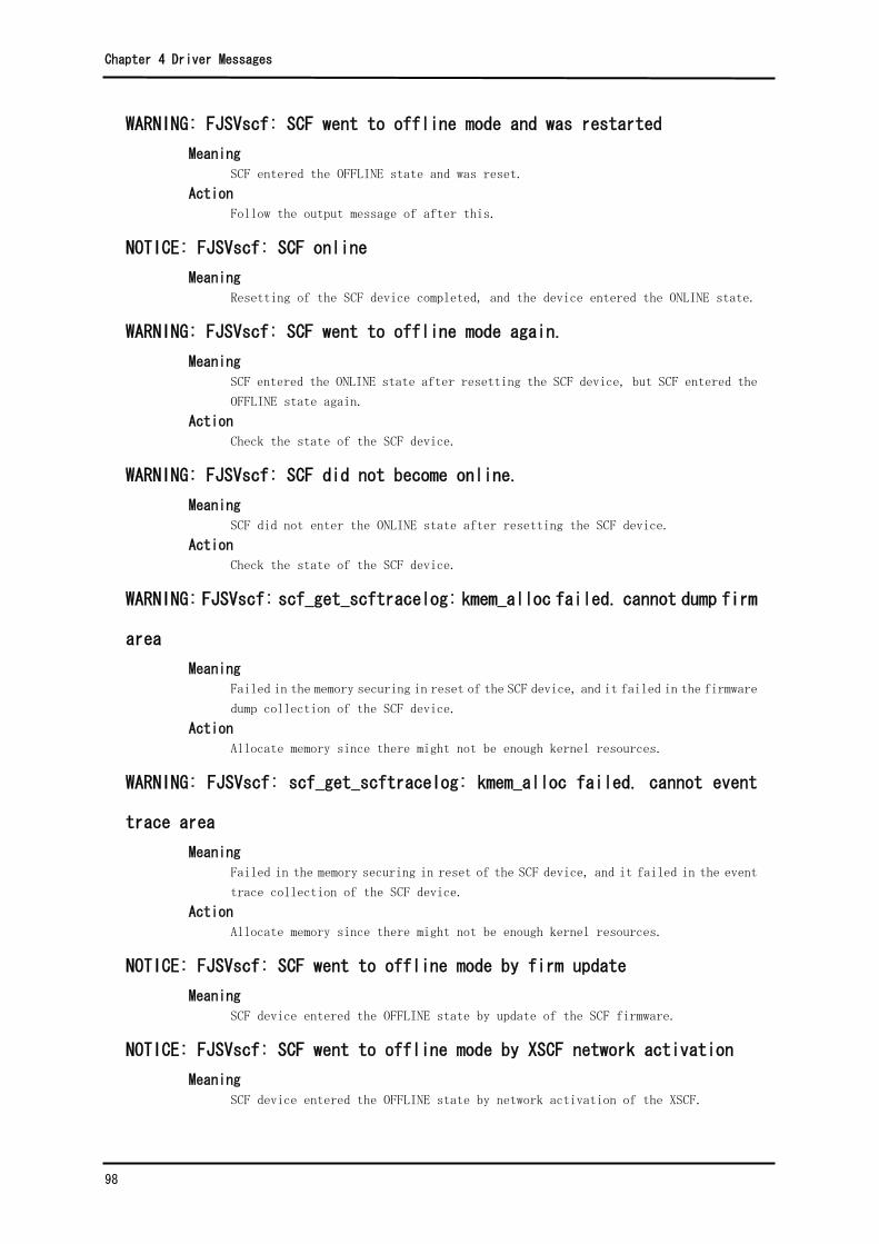
Chapter 4 Driver Messages
WARNING: FJSVscf: SCF went to offline mode and was restarted
Meaning
SCF entered the OFFLINE state and was reset.
Action
Follow the output message of after this.
NOTICE: FJSVscf: SCF online
Meaning
Resetting of the SCF device completed, and the device entered the ONLINE state.
WARNING: FJSVscf: SCF went to offline mode again.
Meaning
SCF entered the ONLINE state after resetting the SCF device, but SCF entered the
OFFLINE state again.
Action
Check the state of the SCF device.
WARNING: FJSVscf: SCF did not become online.
Meaning
SCF did not enter the ONLINE state after resetting the SCF device.
Action
Check the state of the SCF device.
WARNING: FJSVscf: scf_get_scftracelog: kmem_alloc failed. cannot dump firm
area
Meaning
Failed in the memory securing in reset of the SCF device, and it failed in the firmware
dump collection of the SCF device.
Action
Allocate memory since there might not be enough kernel resources.
WARNING: FJSVscf: scf_get_scftracelog: kmem_alloc failed. cannot event
trace area
Meaning
Failed in the memory securing in reset of the SCF device, and it failed in the event
trace collection of the SCF device.
Action
Allocate memory since there might not be enough kernel resources.
NOTICE: FJSVscf: SCF went to offline mode by firm update
Meaning
SCF device entered the OFFLINE state by update of the SCF firmware.
NOTICE: FJSVscf: SCF went to offline mode by XSCF network activation
Meaning
SCF device entered the OFFLINE state by network activation of the XSCF.
98
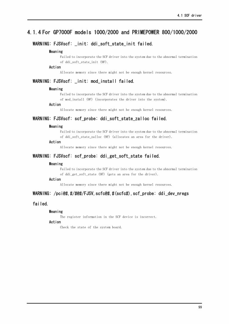
4.1 SCF driver
4.1.4 For GP7000F models 1000/2000 and PRIMEPOWER 800/1000/2000
WARNING: FJSVscf: _init: ddi_soft_state_init failed.
Meaning
Failed to incorporate the SCF driver into the system due to the abnormal termination
of ddi_soft_state_init (9F).
Action
Allocate memory since there might not be enough kernel resources.
WARNING: FJSVscf: _init: mod_install failed.
Meaning
Failed to incorporate the SCF driver into the system due to the abnormal termination
of mod_install (9F) (incorporates the driver into the system).
Action
Allocate memory since there might not be enough kernel resources.
WARNING: FJSVscf: scf_probe: ddi_soft_state_zalloc failed.
Meaning
Failed to incorporate the SCF driver into the system due to the abnormal termination
of ddi_soft_state_zalloc (9F) (allocates an area for the driver).
Action
Allocate memory since there might not be enough kernel resources.
WARNING: FJSVscf: scf_probe: ddi_get_soft_state failed.
Meaning
Failed to incorporate the SCF driver into the system due to the abnormal termination
of ddi_get_soft_state (9F) (gets an area for the driver).
Action
Allocate memory since there might not be enough kernel resources.
WARNING: /pci@#,#/#@#/FJSV,scfc@#,#(scfc#),scf_probe: ddi_dev_nregs
failed.
Meaning
The register information in the SCF device is incorrect.
Action
Check the state of the system board.
99
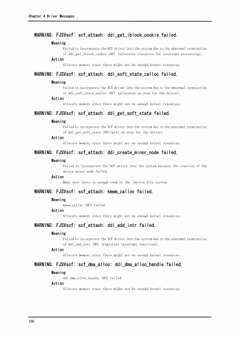
Chapter 4 Driver Messages
WARNING: FJSVscf: scf_attach: ddi_get_iblock_cookie failed.
Meaning
Failed to incorporate the SCF driver into the system due to the abnormal termination
of ddi_get_iblock_cookie (9F) (allocates resources for interrupt processing).
Action
Allocate memory since there might not be enough kernel resources.
WARNING: FJSVscf: scf_attach: ddi_soft_state_zalloc failed.
Meaning
Failed to incorporate the SCF driver into the system due to the abnormal termination
of ddi_soft_state_zalloc (9F) (allocates an area for the driver).
Action
Allocate memory since there might not be enough kernel resources.
WARNING: FJSVscf: scf_attach: ddi_get_soft_state failed.
Meaning
Failed to incorporate the SCF driver into the system due to the abnormal termination
of ddi_get_soft_state (9F)(gets an area for the driver).
Action
Allocate memory since there might not be enough kernel resources.
WARNING: FJSVscf: scf_attach: ddi_create_minor_node failed.
Meaning
Failed to incorporate the SCF driver into the system because the creation of the
device minor node failed.
Action
Make sure there is enough room in the /device file system.
WARNING: FJSVscf: scf_attach: kmem_zalloc failed.
Meaning
kmem_zalloc (9F) failed.
Action
Allocate memory since there might not be enough kernel resources.
WARNING: FJSVscf: scf_attach: ddi_add_intr failed.
Meaning
Failed to incorporate the SCF driver into the system due to the abnormal termination
of ddi_add_intr (9F) (registers interrupt functions).
Action
Allocate memory since there might not be enough kernel resources.
WARNING: FJSVscf: scf_dma_alloc: ddi_dma_alloc_handle failed.
Meaning
ddi_dma_alloc_handle (9F) failed.
Action
Allocate memory since there might not be enough kernel resources.
100
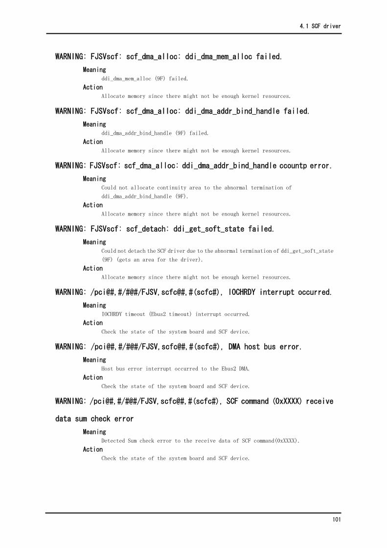
4.1 SCF driver
WARNING: FJSVscf: scf_dma_alloc: ddi_dma_mem_alloc failed.
Meaning
ddi_dma_mem_alloc (9F) failed.
Action
Allocate memory since there might not be enough kernel resources.
WARNING: FJSVscf: scf_dma_alloc: ddi_dma_addr_bind_handle failed.
Meaning
ddi_dma_addr_bind_handle (9F) failed.
Action
Allocate memory since there might not be enough kernel resources.
WARNING: FJSVscf: scf_dma_alloc: ddi_dma_addr_bind_handle ccountp error.
Meaning
Could not allocate continuity area to the abnormal termination of
ddi_dma_addr_bind_handle (9F).
Action
Allocate memory since there might not be enough kernel resources.
WARNING: FJSVscf: scf_detach: ddi_get_soft_state failed.
Meaning
Could not detach the SCF driver due to the abnormal termination of ddi_get_soft_state
(9F) (gets an area for the driver).
Action
Allocate memory since there might not be enough kernel resources.
WARNING: /pci@#,#/#@#/FJSV,scfc@#,#(scfc#), IOCHRDY interrupt occurred.
Meaning
IOCHRDY timeout (Ebus2 timeout) interrupt occurred.
Action
Check the state of the system board and SCF device.
WARNING: /pci@#,#/#@#/FJSV,scfc@#,#(scfc#), DMA host bus error.
Meaning
Host bus error interrupt occurred to the Ebus2 DMA.
Action
Check the state of the system board and SCF device.
WARNING: /pci@#,#/#@#/FJSV,scfc@#,#(scfc#), SCF command (0xXXXX) receive
data sum check error
Meaning
Detected Sum check error to the receive data of SCF command(0xXXXX).
Action
Check the state of the system board and SCF device.
101
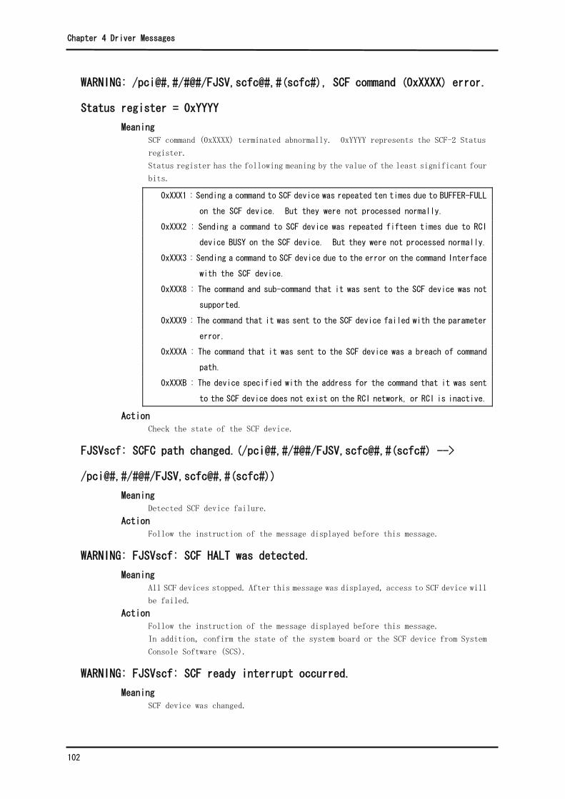
Chapter 4 Driver Messages
WARNING: /pci@#,#/#@#/FJSV,scfc@#,#(scfc#), SCF command (0xXXXX) error.
Status register = 0xYYYY
Meaning
SCF command (0xXXXX) terminated abnormally. 0xYYYY represents the SCF-2 Status
register.
Status register has the following meaning by the value of the least significant four
bits.
0xXXX1 : Sending a command to SCF device was repeated ten times due to BUFFER-FULL
on the SCF device. But they were not processed normally.
0xXXX2 : Sending a command to SCF device was repeated fifteen times due to RCI
device BUSY on the SCF device. But they were not processed normally.
0xXXX3 : Sending a command to SCF device due to the error on the command Interface
with the SCF device.
0xXXX8 : The command and sub-command that it was sent to the SCF device was not
supported.
0xXXX9 : The command that it was sent to the SCF device failed with the parameter
error.
0xXXXA : The command that it was sent to the SCF device was a breach of command
path.
0xXXXB : The device specified with the address for the command that it was sent
to the SCF device does not exist on the RCI network, or RCI is inactive.
Action
Check the state of the SCF device.
FJSVscf: SCFC path changed.(/pci@#,#/#@#/FJSV,scfc@#,#(scfc#) -->
/pci@#,#/#@#/FJSV,scfc@#,#(scfc#))
Meaning
Detected SCF device failure.
Action
Follow the instruction of the message displayed before this message.
WARNING: FJSVscf: SCF HALT was detected.
Meaning
All SCF devices stopped. After this message was displayed, access to SCF device will
be failed.
Action
Follow the instruction of the message displayed before this message.
In addition, confirm the state of the system board or the SCF device from System
Console Software (SCS).
WARNING: FJSVscf: SCF ready interrupt occurred.
Meaning
SCF device was changed.
102
4.1 SCF driver
WARNING: FJSVscf: /pci@#,#/#@#/FJSV,scfc@#,#(scfc#), SCF command (0xXXXX)
timeout
Meaning
The SCF command (0xXXXX) could not complete a command within the prescribed time.
Action
Check the state of the system board and SCF device.
WARNING: FJSVscf: /pci@#,#/#@#/FJSV,scfc@#,#(scfc#), XXX register read
error
Meaning
Recovered by re-reading thought an I/O register reading error occurred.
XXX is register name.
SCF-2 command
SCF-2 Status
SCF-2 tx data
SCF-2 rx data
SCF-2 control
SCF-2 interrupt status
Ebus-2 dma control
DMA csr
DMA address control
DMA byte control
WARNING: /pci@#,#/#@#/FJSV,scfc@#,#(scfc#),offline
Meaning
Detected SCF device failure.
Action
Check the state of the system board and SCF device.
WARNING: FJSVscf: scf_intr: Unexpected POFF interrupt occurred
Meaning
A POWER switch interrupt occurred while the mode switch on the operator panel was
set to LOCK.
Action
Check the state of the mode switch.
WARNING: FJSVscf: AC power down was detected. UPS is activated. RCI(addr
= 0xXXXXXXXX)
Meaning
Power is now being supplied by the UPS due to a power down.
Action
Check the state of the power supply.
103
Chapter 4 Driver Messages
FJSVscf: AC power recovered. RCI(addr = 0xXXXXXXXX)
Meaning
Power was restored on the RCI device (0xXXXXXXXX).
WARNING: FJSVscf: fan unit failure on RCI(addr = 0xXXXXXXXX), FAN#?, sub
status = 0xX1,
sense info = 0xXX 0xXX 0xXX 0xXX 0xZZ 0xYY 0xNN 0x00
Meaning
Detected a fan unit failure (sub status=0x01 or 0x81) on RCI device (addr =
0xXXXXXXXX).
This message displays abnormality that this system detected, and abnormality that
another device connected on the RCI network detected.
When "sub status" is 0x81 and this system is abnormal, after this message is displayed
the power off of the system is executed.
When another device on RCI network is abnormal, the abnormal is notified to this
system through RCI.
FAN#? represents the fan unit number.
Sense info shows the following meanings.
Four bytes of 0xXX show the address of the RCI device, and are the same as "addr
= 0xXXXXXXXX".
0xZZ shows the event code.
0x01 : Fan rotation decrease
0x02 : Fan rotation stop
0xYY is fan number, and the number which depends on the corresponding RCI device.
0xNN is fan tray number, and the number which depends on the corresponding RCI device.
Action
When this message is displayed, it is necessary to check the abnormality of the RCI
device displayed with addr.
Check the fan unit of the FAN#? , and please contact our customer engineer.
104

4.1 SCF driver
WARNING: FJSVscf: power supply unit failure on RCI(addr = 0xXXXXXXXX),
AAA#?, sub status = 0xX2,
sense info = 0xXX 0xXX 0xXX 0xXX 0xZZ 0xYY 0xNN 0x00
Meaning
Detected a power supply unit failure (sub status=0x02 or 0x82) on RCI device (addr
= 0xXXXXXXXX).
This message displays abnormality that this system detected, and abnormality that
another device connected on the RCI network detected.
When "sub status" is 0x82 and this system is abnormal, after this message is displayed
the power off of the system is executed.
When another device on RCI network is abnormal, the abnormal is notified to this
system through RCI.
AAA represents the power supply unit name. #? represents the power supply unit
number.
FEP
SB
XB-DDC
Sense info shows the following meanings.
Four bytes of 0xXX show the address of the RCI device, and are the same as "addr
= 0xXXXXXXXX".
0xZZ shows the event code.
0x00 : An abnormal power supply unit cannot be specified.
0x01-04 : Power supply and voltage are abnormal.
0x05 : Power supply unit which depends on device is abnormal.
0xYY is detailed information which supplements the event code (0xZZ).
00xNN is a power supply unit type or number, and it depends on the corresponding
RCI device.
Action
When this message is displayed, it is necessary to check the abnormality of the RCI
device displayed with addr.
Check the power supply unit of the AAA#?, and please contact our customer engineer.
105

Chapter 4 Driver Messages
WARNING: FJSVscf: thermal alarm on RCI(addr = 0xXXXXXXXX), CPU#?, sub
status = 0xX6,
sense info = 0xXX 0xXX 0xXX 0xXX 0xZZ 0xYY 0x00 0x00
Meaning
Detected an abnormal temperature (sub status=0x06 or 0x86) on RCI device (addr =
0xXXXXXXXX).
This message displays abnormality that this system detected, and abnormality that
another device connected on the RCI network detected.
When "sub status" is 0x86 and this system is abnormal, after this message is displayed
the power off of the system is executed.
When another device on RCI network is abnormal, the abnormal is notified to this
system through RCI.
CPU#? represents the CPU sensor number or sensor number.
Sense info shows the following meanings.
Four bytes of 0xXX show the address of the RCI device, and are the same as "addr
= 0xXXXXXXXX".
0xZZ shows the event code.
0x01 : Ambient temperature low temperature warning
0x02 : Ambient temperature low temperature alarm
0x03 : Ambient temperature high temperature warning
0x04 : Ambient temperature high temperature alarm
0x05 : Unit/Processor low temperature warning, or sensor failure
0x06 : Unit/Processor low temperature alarm, or sensor failure
0x07 : Unit/Processor high temperature warning
0x08 : unit/processor high temperature alarm
0xYY is sensor number, and it depends on the corresponding RCI device.
Action
When this message is displayed, it is necessary to check the abnormality of the RCI
device displayed with addr.
Check the environment where the unit is set up.
Also make sure there is nothing wrong with the inside of the RCI device.
106
4.1 SCF driver
WARNING: FJSVscf: node error on RCI(addr = 0xXXXXXXXX), sub status = 0x08,
sense info = 0xXX 0xXX 0xXX 0xXX 0x00 0xZZ 0xYY 0x00
Meaning
Detected a node error (sub status=0x08) on RCI device (addr = 0xXXXXXXXX).
This message displays abnormality that this system detected, and abnormality that
another device connected on the RCI network detected.
When another device on RCI network is abnormal, the abnormal is notified to this
system through RCI.
Sense info shows the following meanings.
Four bytes of 0xXX show the address of the RCI device, and are the same as "addr
= 0xXXXXXXXX".
0xZZ shows the event code.
0x01 : The internal failure of RCI-I/O device
0x01-05 : SCF unit self-diagnosis error
0x90 : RCI network is abnormal (status check time-out)
0x91 : RCI address multiple error
0x92 : Host node is abnormal
0x93 : RCI device connection failure of unregistration
0x94 : SCF degeneracy
0xc0-ff : Hard error of RCI-I/O device
0xYY shows detailed information of RCI network abnormality (event code 0x90) or host
node abnormality(event code 0x92). Or, when the inside abnormality of RCI-I/O
device (event code 0x00), detailed information that depends on RCI-I/O device is
shown. Other event codes are irregular values, and it does not have the meaning.
Action
When this message is displayed, it is necessary to check the abnormality of the RCI
device displayed with addr.
Check RCI address is uniquely assigned to each RCI device, there are no RCI cable
problems, RCI device are turned power on, unconfigured RCI devices are not connected
or there are no internal failure in RCI devices. Please contact our customer
engineer.
107
Chapter 4 Driver Messages
panic[cpuX]/thread = 0xXXXXXXXX: FJSVscf: panic request from RCI(addr =
0xXXXXXXXX)
Meaning
The RCI device that has RCI address of 0xXXXXXXXX requested the system panic.
Action
This message shows the state.
However, at the cluster environment etc. , another node (RCI address 0xXXXXXXXX)
which detected abnormality issues the panic instruction to this node via RCI. And,
when OS panic is executed, this node outputs this message.
Please investigate this node from information on another node (RCI address
0xXXXXXXXX).
NOTICE: FJSVscf: I/O node status sense from RCI(addr = 0xXXXXXXXX),sub
status = 0x62,
sense info = 0xXX 0xXX 0xXX 0xXX 0xZZ 0xYY 0xYY 0xYY
Meaning
Detected a sensed information of I/O node status (sub status=0x062) from RCI device
(addr = 0xXXXXXXXX).
This message displays the change of the state of another device connected on the
RCI network.
Sense info shows the following meanings.
Four bytes of 0xXX show the address of the RCI device, and are the same as "addr
= 0xXXXXXXXX".
0xZZ shows the event code.
0x01 : RCI-I/O device connection or power supply reentry
0x02 : RCI-I/O device disconnect
0xYY is type or number of RCI-I/O device, and it depends on corresponding RCI-I/O
device.
Action
It is not necessary.
When this message is frequently displayed, it is necessary to investigate the RCI
device, and please contact our customer engineer.
108
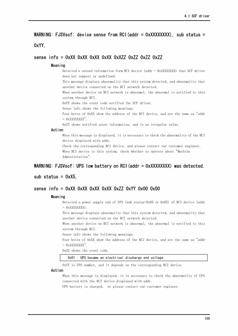
4.1 SCF driver
WARNING: FJSVscf: device sense from RCI(addr = 0xXXXXXXXX), sub status =
0xYY,
sense info = 0xXX 0xXX 0xXX 0xXX 0xXZZ 0xZZ 0xZZ 0xZZ
Meaning
Detected a sensed information form RCI device (addr = 0xXXXXXXXX) that SCF driver
does not support or undefined.
This message displays abnormality that this system detected, and abnormality that
another device connected on the RCI network detected.
When another device on RCI network is abnormal, the abnormal is notified to this
system through RCI.
0xYY shows the event code notified the SCF driver.
Sense info shows the following meanings.
Four bytes of 0xXX show the address of the RCI device, and are the same as "addr
= 0xXXXXXXXX".
0xZZ shows notified sense information, and is an irregular value.
Action
When this message is displayed, it is necessary to check the abnormality of the RCI
device displayed with addr.
Check the corresponding RCI device, and please contact our customer engineer.
When RCI device is this system, check whether to operate about "Machine
Administration".
WARNING: FJSVscf: UPS low battery on RCI(addr = 0xXXXXXXXX) was detected.
sub status = 0xX5,
sense info = 0xXX 0xXX 0xXX 0xXX 0xZZ 0xYY 0x00 0x00
Meaning
Detected a power supply end of UPS (sub status=0x05 or 0x85) of RCI device (addr
= 0xXXXXXXXX).
This message displays abnormality that this system detected, and abnormality that
another device connected on the RCI network detected.
When another device on RCI network is abnormal, the abnormal is notified to this
system through RCI.
Sense info shows the following meanings.
Four bytes of 0xXX show the address of the RCI device, and are the same as "addr
= 0xXXXXXXXX".
0xZZ shows the event code.
0x01 : UPS became an electrical discharge end voltage.
0xYY is UPS number, and it depends on the corresponding RCI device.
Action
When this message is displayed, it is necessary to check the abnormality of UPS
connected with the RCI device displayed with addr.
UPS battery is charged, or please contact our customer engineer.
109

Chapter 4 Driver Messages
WARNING: FJSVscf: UPS failure on RCI(addr = 0xXXXXXXXX) was detected. sub
status = 0xX5,
sense info = 0xXX 0xXX 0xXX 0xXX 0xZZ 0xYY 0xYY 0x00
Meaning
Detected a UPS failure (sub status=0x05 or 0x85) of RCI device (addr = 0xXXXXXXXX).
This message displays abnormality that this system detected, and abnormality that
another device connected on the RCI network detected.
When another device on RCI network is abnormal, the abnormal is notified to this
system through RCI.
Sense info shows the following meanings.
Four bytes of 0xXX show the address of the RCI device, and are the same as "addr
= 0xXXXXXXXX".
0xZZ shows the event code.
0x02 : UPS hardware failure
0x03 : UPS battery failure
0x04 : UPS circuit protector failure
0xYY is UPS number and detail information, and it depends on the corresponding RCI
device.
Action
When this message is displayed, it is necessary to check the abnormality of UPS
connected with the RCI device displayed with addr..
Check to make sure that nothing is wrong with the UPS, or please contact our customer
engineer.
WARNING: FJSVscf: cannot report PANIC.
Meaning
Could not notify the system panic on the other HOST when it occurred.
WARNING: FJSVscf: scf_map_regs: ddi_dev_regsize failed.
Meaning
Failed to incorporate the SCF driver into the system due to the abnormal termination
of ddi_dev_regsize (9F) (gets the register size).
Action
Check the state of the SCF device.
WARNING: FJSVscf: scf_map_regs: ddi_regs_map_setup failed.
Meaning
Failed to incorporate the SCF driver into the system due to the abnormal termination
of ddi_regs_map_setup (9F) (maps register).
Action
Allocate memory since there might not be enough kernel resources.
110
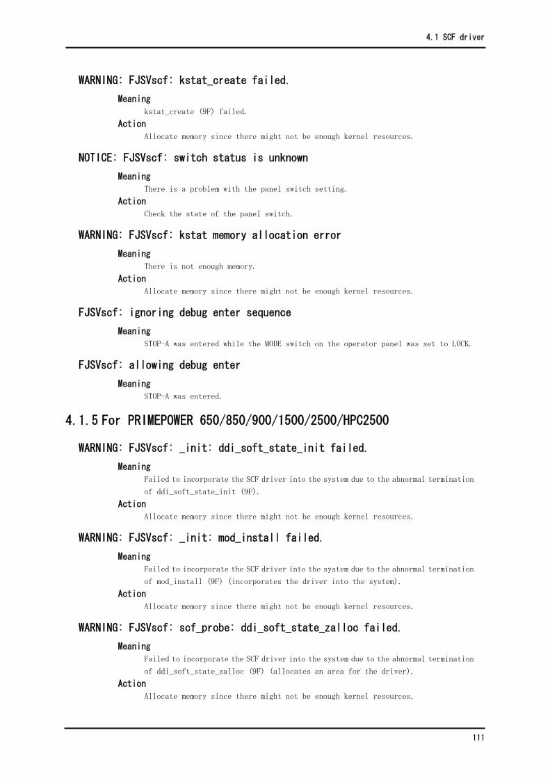
4.1 SCF driver
WARNING: FJSVscf: kstat_create failed.
Meaning
kstat_create (9F) failed.
Action
Allocate memory since there might not be enough kernel resources.
NOTICE: FJSVscf: switch status is unknown
Meaning
There is a problem with the panel switch setting.
Action
Check the state of the panel switch.
WARNING: FJSVscf: kstat memory allocation error
Meaning
There is not enough memory.
Action
Allocate memory since there might not be enough kernel resources.
FJSVscf: ignoring debug enter sequence
Meaning
STOP-A was entered while the MODE switch on the operator panel was set to LOCK.
FJSVscf: allowing debug enter
Meaning
STOP-A was entered.
4.1.5 For PRIMEPOWER 650/850/900/1500/2500/HPC2500
WARNING: FJSVscf: _init: ddi_soft_state_init failed.
Meaning
Failed to incorporate the SCF driver into the system due to the abnormal termination
of ddi_soft_state_init (9F).
Action
Allocate memory since there might not be enough kernel resources.
WARNING: FJSVscf: _init: mod_install failed.
Meaning
Failed to incorporate the SCF driver into the system due to the abnormal termination
of mod_install (9F) (incorporates the driver into the system).
Action
Allocate memory since there might not be enough kernel resources.
WARNING: FJSVscf: scf_probe: ddi_soft_state_zalloc failed.
Meaning
Failed to incorporate the SCF driver into the system due to the abnormal termination
of ddi_soft_state_zalloc (9F) (allocates an area for the driver).
Action
Allocate memory since there might not be enough kernel resources.
111

Chapter 4 Driver Messages
WARNING: FJSVscf: scf_probe: ddi_get_soft_state failed.
Meaning
Failed to incorporate the SCF driver into the system due to the abnormal termination
of ddi_get_soft_state (9F) (gets an area for the driver).
Action
Allocate memory since there might not be enough kernel resources.
WARNING: /pci@#,#/#@#/FJSV,scfc@#,#(scfc#),scf_probe: ddi_dev_nregs
failed.
Meaning
The register information in the SCF device is incorrect.
Action
Check the state of the system board.
WARNING: FJSVscf: scf_attach: ddi_get_iblock_cookie failed.
Meaning
Failed to incorporate the SCF driver into the system due to the abnormal termination
of ddi_get_iblock_cookie (9F) (allocates resources for interrupt processing).
Action
Allocate memory since there might not be enough kernel resources.
WARNING: FJSVscf: scf_attach: ddi_soft_state_zalloc failed.
Meaning
Failed to incorporate the SCF driver into the system due to the abnormal termination
of ddi_soft_state_zalloc (9F) (allocates an area for the driver).
Action
Allocate memory since there might not be enough kernel resources.
WARNING: FJSVscf: scf_attach: ddi_get_soft_state failed.
Meaning
Failed to incorporate the SCF driver into the system due to the abnormal termination
of ddi_get_soft_state (9F) (gets an area for the driver).
Action
Allocate memory since there might not be enough kernel resources.
WARNING: FJSVscf: scf_attach: ddi_create_minor_node failed.
Meaning
Failed to incorporate the SCF driver into the system because the creation of the
device minor node failed.
Action
Make sure there is enough room in the /device file system.
WARNING: FJSVscf: scf_attach: kmem_zalloc failed.
Meaning
kmem_zalloc (9F) failed.
Action
Allocate memory since there might not be enough kernel resources.
112

4.1 SCF driver
WARNING: FJSVscf: scf_attach: ddi_add_intr failed.
Meaning
Failed to incorporate the SCF driver into the system due to the abnormal termination
of ddi_add_intr (9F) (registers interrupt functions).
Action
Allocate memory since there might not be enough kernel resources.
WARNING: FJSVscf: scf_attach: ddi_get_soft_iblock_cookie failed.
Meaning
Failed to incorporate the SCF driver into the system due to the abnormal termination
of ddi_get_soft_iblock_cookie (9F) (allocates resources for soft interrupt
processing).
Action
Allocate memory since there might not be enough kernel resources.
WARNING: FJSVscf: scf_attach: ddi_add_softintr failed.
Meaning
Failed to incorporate the SCF driver into the system due to the abnormal termination
of ddi_add_softintr (9F) (registers soft interrupt functions).
Action
Allocate memory since there might not be enough kernel resources.
WARNING: FJSVscf: scf_dma_alloc: ddi_dma_alloc_handle failed.
Meaning
ddi_dma_alloc_handle (9F) failed.
Action
Allocate memory since there might not be enough kernel resources.
WARNING: FJSVscf: scf_dma_alloc: ddi_dma_mem_alloc failed.
Meaning
ddi_dma_mem_alloc (9F) failed.
Action
Allocate memory since there might not be enough kernel resources.
WARNING: FJSVscf: scf_dma_alloc: ddi_dma_addr_bind_handle failed.
Meaning
ddi_dma_addr_bind_handle (9F) failed.
Action
Allocate memory since there might not be enough kernel resources.
WARNING: FJSVscf: scf_dma_alloc: ddi_dma_addr_bind_handle ccountp error.
Meaning
Could not allocate continuity area to the abnormal termination of
ddi_dma_addr_bind_handle (9F).
Action
Allocate memory since there might not be enough kernel resources.
113
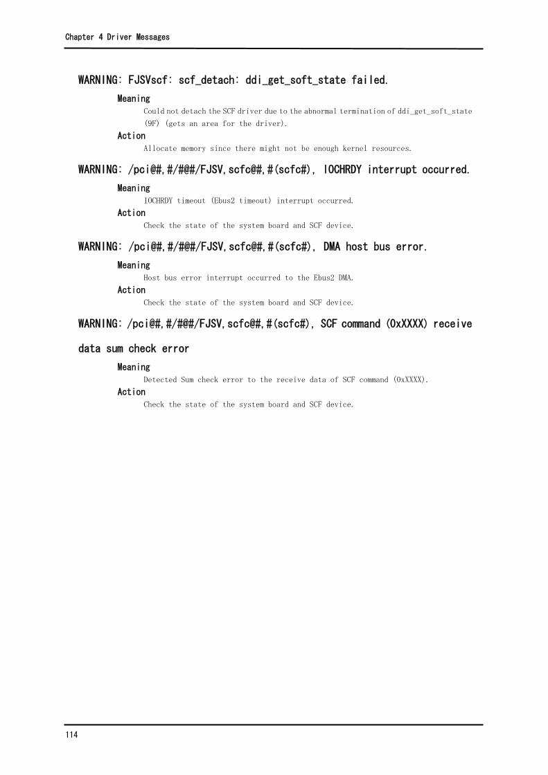
Chapter 4 Driver Messages
WARNING: FJSVscf: scf_detach: ddi_get_soft_state failed.
Meaning
Could not detach the SCF driver due to the abnormal termination of ddi_get_soft_state
(9F) (gets an area for the driver).
Action
Allocate memory since there might not be enough kernel resources.
WARNING: /pci@#,#/#@#/FJSV,scfc@#,#(scfc#), IOCHRDY interrupt occurred.
Meaning
IOCHRDY timeout (Ebus2 timeout) interrupt occurred.
Action
Check the state of the system board and SCF device.
WARNING: /pci@#,#/#@#/FJSV,scfc@#,#(scfc#), DMA host bus error.
Meaning
Host bus error interrupt occurred to the Ebus2 DMA.
Action
Check the state of the system board and SCF device.
WARNING: /pci@#,#/#@#/FJSV,scfc@#,#(scfc#), SCF command (0xXXXX) receive
data sum check error
Meaning
Detected Sum check error to the receive data of SCF command (0xXXXX).
Action
Check the state of the system board and SCF device.
114
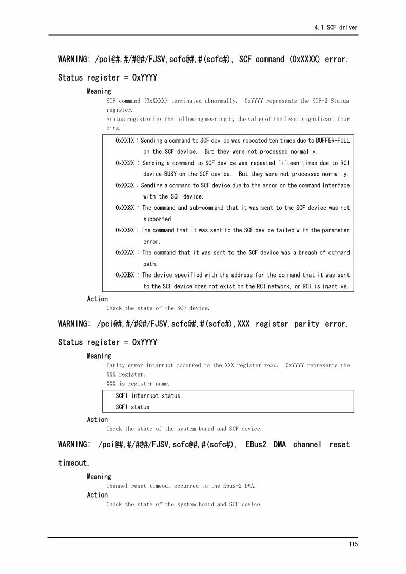
4.1 SCF driver
WARNING: /pci@#,#/#@#/FJSV,scfc@#,#(scfc#), SCF command (0xXXXX) error.
Status register = 0xYYYY
Meaning
SCF command (0xXXXX) terminated abnormally. 0xYYYY represents the SCF-2 Status
register.
Status register has the following meaning by the value of the least significant four
bits.
0xXX1X : Sending a command to SCF device was repeated ten times due to BUFFER-FULL
on the SCF device. But they were not processed normally.
0xXX2X : Sending a command to SCF device was repeated fifteen times due to RCI
device BUSY on the SCF device. But they were not processed normally.
0xXX3X : Sending a command to SCF device due to the error on the command Interface
with the SCF device.
0xXX8X : The command and sub-command that it was sent to the SCF device was not
supported.
0xXX9X : The command that it was sent to the SCF device failed with the parameter
error.
0xXXAX : The command that it was sent to the SCF device was a breach of command
path.
0xXXBX : The device specified with the address for the command that it was sent
to the SCF device does not exist on the RCI network, or RCI is inactive.
Action
Check the state of the SCF device.
WARNING: /pci@#,#/#@#/FJSV,scfc@#,#(scfc#),XXX register parity error.
Status register = 0xYYYY
Meaning
Parity error interrupt occurred to the XXX register read. 0xYYYY represents the
XXX register.
XXX is register name.
SCFI interrupt status
SCFI status
Action
Check the state of the system board and SCF device.
WARNING: /pci@#,#/#@#/FJSV,scfc@#,#(scfc#), EBus2 DMA channel reset
timeout.
Meaning
Channel reset timeout occurred to the Ebus-2 DMA.
Action
Check the state of the system board and SCF device.
115

Chapter 4 Driver Messages
FJSVscf: SCFC path changed.(/pci@#,#/#@#/FJSV,scfc@#,#(scfc#) -->
/pci@#,#/#@#/FJSV,scfc@#,#(scfc#))
Meaning
Detected SCF device failure.
Action
Follow the instruction of the message displayed before this message.
WARNING: FJSVscf: SCF HALT was detected.
Meaning
All SCF devices stopped. After this message was displayed, access to SCF device will
be failed.
Action
Follow the instruction of the message displayed before this message.
In addition, confirm the state of the system board or the SCF device from System
Console Software (SCS) for PRIMEPOWER 900/1500/2500/HPC2500.
WARNING: FJSVscf: SCF ready interrupt occurred.
Meaning
SCF device was changed.
WARNING: FJSVscf: /pci@#,#/#@#/FJSV,scfc@#,#(scfc#), SCF command (0xXXXX)
timeout
Meaning
The SCF command (0xXXXX) could not complete a command within the prescribed time.
Action
Check the state of the system board and SCF device.
116

4.1 SCF driver
WARNING: FJSVscf: /pci@#,#/#@#/FJSV,scfc@#,#(scfc#), XXX register read
error
Meaning
Recovered by re-reading thought an I/O register reading error occurred.
XXX is register name.
SCFI command
SCFI Status
SCFI tx data
SCFI rx data
SCFI control
SCFI interrupt status
Ebus-2 dma control
DMA csr
DMA address control
DMA byte control
LED write enable
internal disk LED control
WARNING: /pci@#,#/#@#/FJSV,scfc@#,#(scfc#),offline
Meaning
Detected SCF device failure.
Action
Check the state of the system board and SCF device.
WARNING: FJSVscf: scf_intr: Unexpected POFF interrupt occurred
Meaning
A POWER switch interrupt occurred while the mode switch on the operator panel was
set to LOCK.
Action
Check the state of the mode switch.
WARNING: FJSVscf: AC power down was detected. UPS is activated. RCI(addr
= 0xXXXXXXXX)
Meaning
Power is now being supplied by the UPS due to a power down.
Action
Check the state of the power supply.
FJSVscf: AC power recovered. RCI(addr = 0xXXXXXXXX)
Meaning
Power was restored on the RCI device (0xXXX).
117
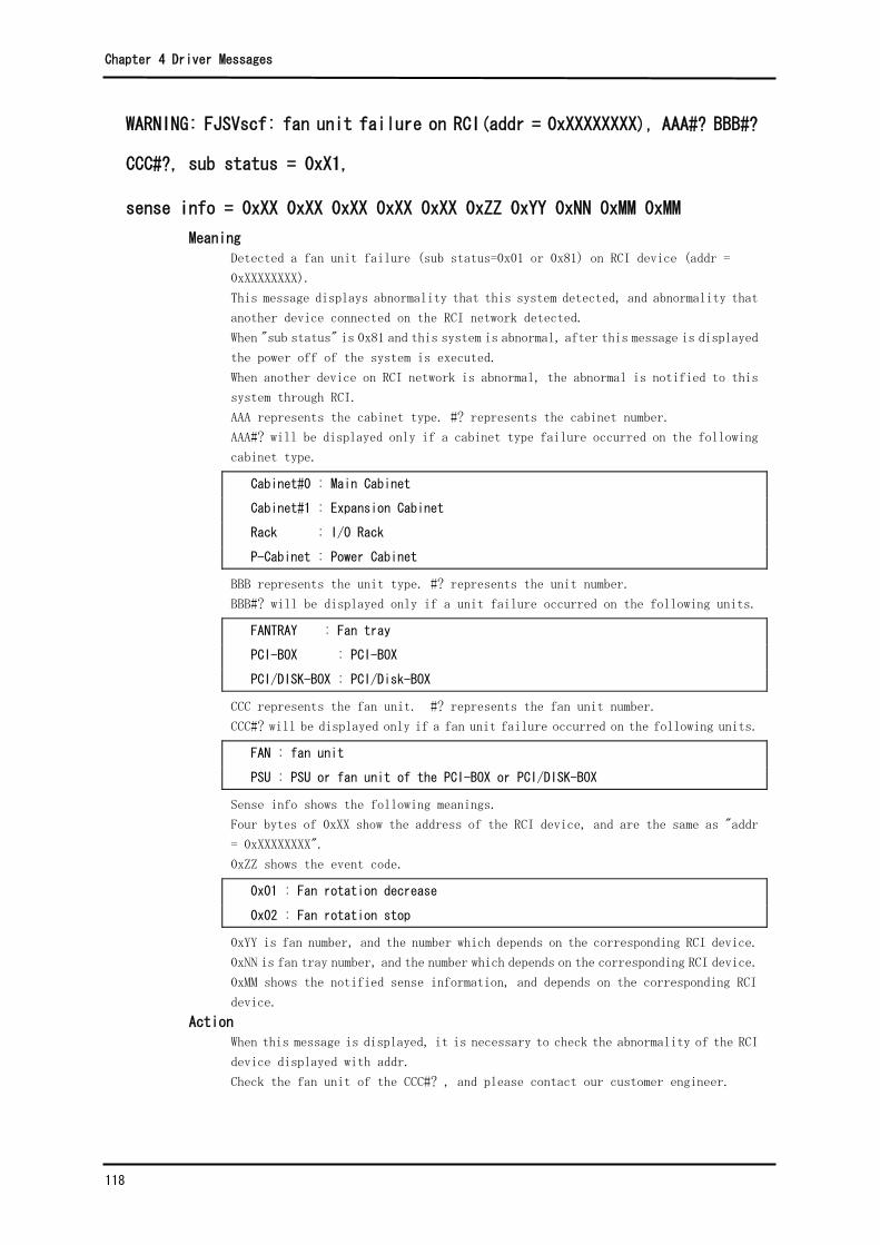
Chapter 4 Driver Messages
WARNING: FJSVscf: fan unit failure on RCI(addr = 0xXXXXXXXX), AAA#? BBB#?
CCC#?, sub status = 0xX1,
sense info = 0xXX 0xXX 0xXX 0xXX 0xXX 0xZZ 0xYY 0xNN 0xMM 0xMM
Meaning
Detected a fan unit failure (sub status=0x01 or 0x81) on RCI device (addr =
0xXXXXXXXX).
This message displays abnormality that this system detected, and abnormality that
another device connected on the RCI network detected.
When "sub status" is 0x81 and this system is abnormal, after this message is displayed
the power off of the system is executed.
When another device on RCI network is abnormal, the abnormal is notified to this
system through RCI.
AAA represents the cabinet type. #? represents the cabinet number.
AAA#? will be displayed only if a cabinet type failure occurred on the following
cabinet type.
Cabinet#0 : Main Cabinet
Cabinet#1 : Expansion Cabinet
Rack : I/O Rack
P-Cabinet : Power Cabinet
BBB represents the unit type. #? represents the unit number.
BBB#? will be displayed only if a unit failure occurred on the following units.
FANTRAY : Fan tray
PCI-BOX : PCI-BOX
PCI/DISK-BOX : PCI/Disk-BOX
CCC represents the fan unit. #? represents the fan unit number.
CCC#? will be displayed only if a fan unit failure occurred on the following units.
FAN : fan unit
PSU : PSU or fan unit of the PCI-BOX or PCI/DISK-BOX
Sense info shows the following meanings.
Four bytes of 0xXX show the address of the RCI device, and are the same as "addr
= 0xXXXXXXXX".
0xZZ shows the event code.
0x01 : Fan rotation decrease
0x02 : Fan rotation stop
0xYY is fan number, and the number which depends on the corresponding RCI device.
0xNN is fan tray number, and the number which depends on the corresponding RCI device.
0xMM shows the notified sense information, and depends on the corresponding RCI
device.
Action
When this message is displayed, it is necessary to check the abnormality of the RCI
device displayed with addr.
Check the fan unit of the CCC#? , and please contact our customer engineer.
118
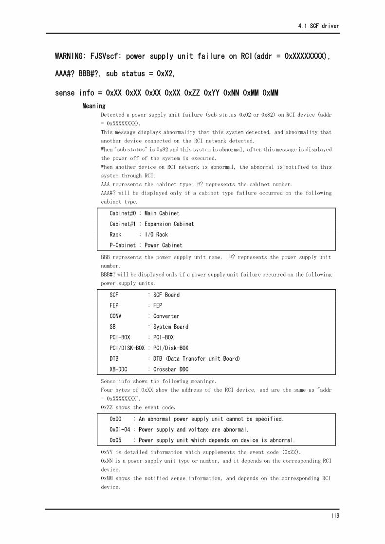
4.1 SCF driver
WARNING: FJSVscf: power supply unit failure on RCI(addr = 0xXXXXXXXX),
AAA#? BBB#?, sub status = 0xX2,
sense info = 0xXX 0xXX 0xXX 0xXX 0xZZ 0xYY 0xNN 0xMM 0xMM
Meaning
Detected a power supply unit failure (sub status=0x02 or 0x82) on RCI device (addr
= 0xXXXXXXXX).
This message displays abnormality that this system detected, and abnormality that
another device connected on the RCI network detected.
When "sub status" is 0x82 and this system is abnormal, after this message is displayed
the power off of the system is executed.
When another device on RCI network is abnormal, the abnormal is notified to this
system through RCI.
AAA represents the cabinet type. #? represents the cabinet number.
AAA#? will be displayed only if a cabinet type failure occurred on the following
cabinet type.
Cabinet#0 : Main Cabinet
Cabinet#1 : Expansion Cabinet
Rack : I/O Rack
P-Cabinet : Power Cabinet
BBB represents the power supply unit name. #? represents the power supply unit
number.
BBB#? will be displayed only if a power supply unit failure occurred on the following
power supply units.
SCF : SCF Board
FEP : FEP
CONV : Converter
SB : System Board
PCI-BOX : PCI-BOX
PCI/DISK-BOX : PCI/Disk-BOX
DTB : DTB (Data Transfer unit Board)
XB-DDC : Crossbar DDC
Sense info shows the following meanings.
Four bytes of 0xXX show the address of the RCI device, and are the same as "addr
= 0xXXXXXXXX".
0xZZ shows the event code.
0x00 : An abnormal power supply unit cannot be specified.
0x01-04 : Power supply and voltage are abnormal.
0x05 : Power supply unit which depends on device is abnormal.
0xYY is detailed information which supplements the event code (0xZZ).
0xNN is a power supply unit type or number, and it depends on the corresponding RCI
device.
0xMM shows the notified sense information, and depends on the corresponding RCI
device.
119

Chapter 4 Driver Messages
Action
When this message is displayed, it is necessary to check the abnormality of the RCI
device displayed with addr.
Check the power supply unit of the BBB#?, and please contact our customer engineer.
WARNING: FJSVscf: thermal alarm on RCI(addr = 0xXXXXXXXX), AAA#? BBB#?
CCC#?, sub status = 0xX6,
sense info = 0xXX 0xXX 0xXX 0xXX 0xZZ 0xYY 0xNN 0xNN 0xNN
Meaning
Detected an abnormal temperature (sub status=0x06 or 0x86) on RCI device (addr =
0xXXXXXXXX).
This message displays abnormality that this system detected, and abnormality that
another device connected on the RCI network detected.
When "sub status" is 0x86 and this system is abnormal, after this message is displayed
the power off of the system is executed.
When another device on RCI network is abnormal, the abnormal is notified to this
system through RCI.
AAA represents the cabinet type. #? represents the cabinet number.
AAA#? will be displayed only if a cabinet type failure occurred on the following
cabinet type.
Cabinet#0 : Main Cabinet
Cabinet#1 : Expansion Cabinet
Rack : I/O Rack
P-Cabinet : Power Cabinet
BBB represents the unit type. #? represents the unit number.
BBB#? will be displayed only if a unit failure occurred on the following units.
SB : System Board
PCI-BOX : PCI-BOX
PCI/DISK-BOX : PCI/Disk BOX
DISK : DISK Bay Unit
XB : Crossbar
EXT-PWR : Power Unit
CCC represents the sensor type. #? represents the sensor number.
CCC#? will be displayed only if a sensor failure occurred on the following sensors.
CPU
SENSOR
Sense info shows the following meanings.
Four bytes of 0xXX show the address of the RCI device, and are the same as "addr
= 0xXXXXXXXX".
0xZZ shows the event code.
120
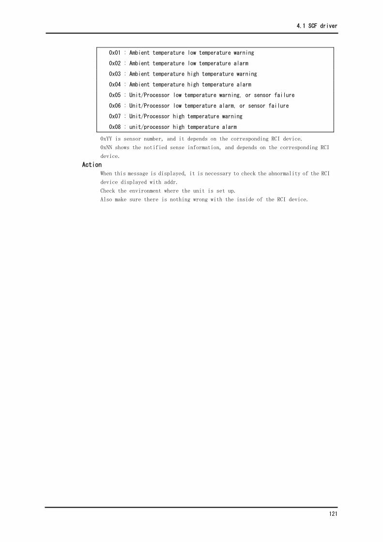
4.1 SCF driver
0x01 : Ambient temperature low temperature warning
0x02 : Ambient temperature low temperature alarm
0x03 : Ambient temperature high temperature warning
0x04 : Ambient temperature high temperature alarm
0x05 : Unit/Processor low temperature warning, or sensor failure
0x06 : Unit/Processor low temperature alarm, or sensor failure
0x07 : Unit/Processor high temperature warning
0x08 : unit/processor high temperature alarm
0xYY is sensor number, and it depends on the corresponding RCI device.
0xNN shows the notified sense information, and depends on the corresponding RCI
device.
Action
When this message is displayed, it is necessary to check the abnormality of the RCI
device displayed with addr.
Check the environment where the unit is set up.
Also make sure there is nothing wrong with the inside of the RCI device.
121

Chapter 4 Driver Messages
WARNING: FJSVscf: node error on RCI(addr = 0xXXXXXXXX), sub status = 0x08,
sense info = 0xXX 0xXX 0xXX 0xXX 0x00 0xZZ 0xYY 0xYY
Meaning
Detected a node error (sub status=0x08) on RCI device (addr = 0xXXXXXXXX).
This message displays abnormality that this system detected, and abnormality that
another device connected on the RCI network detected.
When another device on RCI network is abnormal, the abnormal is notified to this
system through RCI.
Sense info shows the following meanings.
Four bytes of 0xXX show the address of the RCI device, and are the same as "addr
= 0xXXXXXXXX".
0xZZ shows the event code.
0x01 : The internal failure of RCI-I/O device
0x01-05 : SCF unit self-diagnosis error
0x90 : RCI network is abnormal (status check time-out)
0x91 : RCI address multiple error
0x92 : Host node is abnormal
0x93 : RCI device connection failure of unregistration
0x94 : SCF degeneracy
0xc0-ff : Hard error of RCI-I/O device
0xYY shows detailed information of RCI network abnormality (event code 0x90) or host
node abnormality (event code 0x92). Or, when the inside abnormality of RCI-I/O
device (event code 0x00), detailed information that depends on RCI-I/O device is
shown. Other event codes are irregular values, and it does not have the meaning.
Action
When this message is displayed, it is necessary to check the abnormality of the RCI
device displayed with addr.
Check RCI address is uniquely assigned to each RCI device, there are no RCI cable
problems, RCI device are turned power on, unconfigured RCI devices are not connected
or there are no internal failure in RCI devices. Please contact our customer
engineer.
122
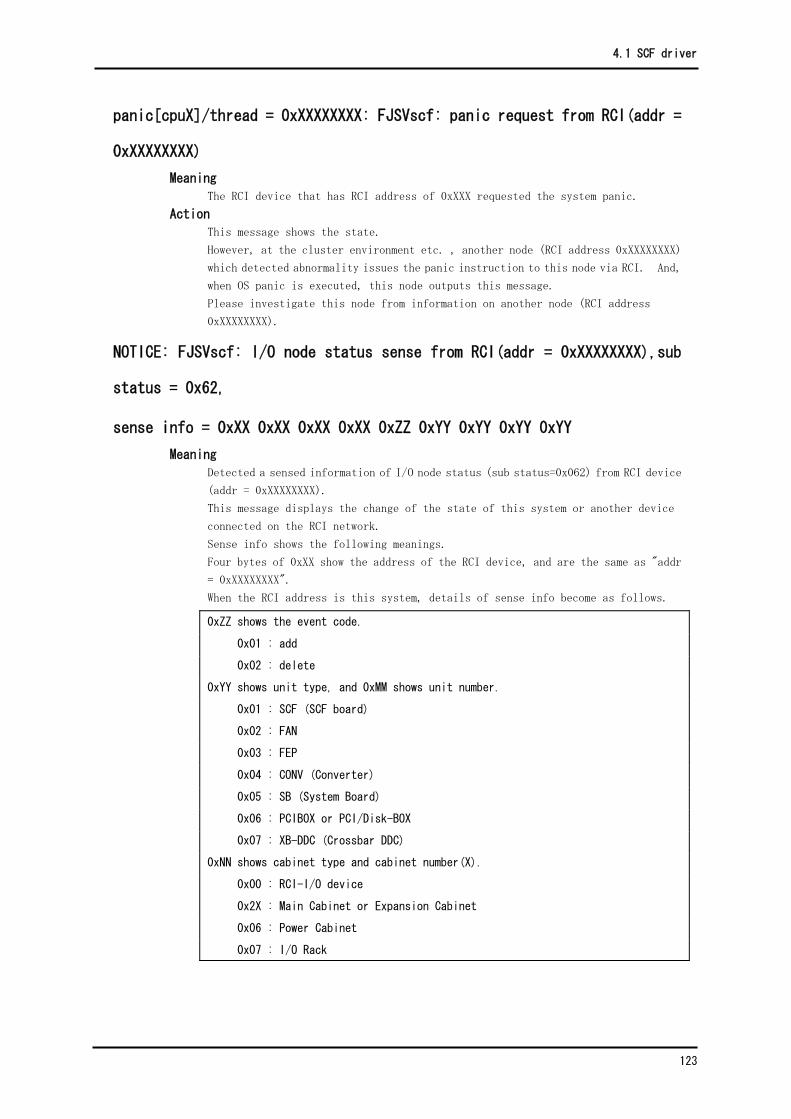
4.1 SCF driver
panic[cpuX]/thread = 0xXXXXXXXX: FJSVscf: panic request from RCI(addr =
0xXXXXXXXX)
Meaning
The RCI device that has RCI address of 0xXXX requested the system panic.
Action
This message shows the state.
However, at the cluster environment etc. , another node (RCI address 0xXXXXXXXX)
which detected abnormality issues the panic instruction to this node via RCI. And,
when OS panic is executed, this node outputs this message.
Please investigate this node from information on another node (RCI address
0xXXXXXXXX).
NOTICE: FJSVscf: I/O node status sense from RCI(addr = 0xXXXXXXXX),sub
status = 0x62,
sense info = 0xXX 0xXX 0xXX 0xXX 0xZZ 0xYY 0xYY 0xYY 0xYY
Meaning
Detected a sensed information of I/O node status (sub status=0x062) from RCI device
(addr = 0xXXXXXXXX).
This message displays the change of the state of this system or another device
connected on the RCI network.
Sense info shows the following meanings.
Four bytes of 0xXX show the address of the RCI device, and are the same as "addr
= 0xXXXXXXXX".
When the RCI address is this system, details of sense info become as follows.
0xZZ shows the event code.
0x01 : add
0x02 : delete
0xYY shows unit type, and 0xMM shows unit number.
0x01 : SCF (SCF board)
0x02 : FAN
0x03 : FEP
0x04 : CONV (Converter)
0x05 : SB (System Board)
0x06 : PCIBOX or PCI/Disk-BOX
0x07 : XB-DDC (Crossbar DDC)
0xNN shows cabinet type and cabinet number(X).
0x00 : RCI-I/O device
0x2X : Main Cabinet or Expansion Cabinet
0x06 : Power Cabinet
0x07 : I/O Rack
123

Chapter 4 Driver Messages
When the RCI address is another device, details of sense info become as follows.
0xZZ shows the event code.
0x01 : RCI-I/O device connection or power supply reentry
0x02 : RCI-I/O device disconnect
0xYY is type or number of RCI-I/O device, and it depends on corresponding RCI-I/O
device.
Action
It is not necessary.
This message might be output in this system at maintenance.
When this message is frequently displayed, it is necessary to investigate. Please
contact our customer engineer.
WARNING: FJSVscf: device sense from RCI(addr = 0xXXXXXXXX), sub status =
0xYY,
sense info = 0xXX 0xXX 0xXX 0xXX 0xZZ 0xZZ 0xZZ 0xZZ 0xZZ
Meaning
Detected a sensed information form RCI device (addr = 0xXXXXXXXX) that SCF driver
does not support or undefined.
This message displays abnormality that this system detected, and abnormality that
another device connected on the RCI network detected.
When another device on RCI network is abnormal, the abnormal is notified to this
system through RCI.
0xYY shows the event code notified the SCF driver.
Sense info shows the following meanings.
Four bytes of 0xXX show the address of the RCI device, and are the same as "addr
= 0xXXXXXXXX".
0xZZ shows notified sense information, and is an irregular value.
Action
When this message is displayed, it is necessary to check the abnormality of the RCI
device displayed with addr.
Check the corresponding RCI device, and please contact our customer engineer.
When RCI device is this system, check whether to operate about "Machine
Administration".
124
4.1 SCF driver
WARNING: FJSVscf: UPS low battery on RCI(addr = 0xXXXXXXXX) was detected.
sub status = 0xX5,
sense info = 0xXX 0xXX 0xXX 0xXX 0xZZ 0xYY 0x00 0x00
Meaning
Detected a power supply end of UPS (sub status=0x05 or 0x85) of RCI device (addr
= 0xXXXXXXXX).
This message displays abnormality that this system detected, and abnormality that
another device connected on the RCI network detected.
When another device on RCI network is abnormal, the abnormal is notified to this
system through RCI.
Sense info shows the following meanings.
Four bytes of 0xXX show the address of the RCI device, and are the same as "addr
= 0xXXXXXXXX".
0xZZ shows the event code.
0x01 : UPS became an electrical discharge end voltage.
0xYY is UPS number, and it depends on the corresponding RCI device.
Action
When this message is displayed, it is necessary to check the abnormality of UPS
connected with the RCI device displayed with addr.
UPS battery is charged, or please contact our customer engineer.
WARNING: FJSVscf: UPS failure on RCI(addr = 0xXXXXXXXX) was detected. sub
status = 0xX5,
sense info = 0xXX 0xXX 0xXX 0xXX 0xZZ 0xYY 0x00 0x00
Meaning
Detected a UPS failure (sub status=0x05 or 0x85) of RCI device (addr = 0xXXXXXXXX).
This message displays abnormality that this system detected, and abnormality that
another device connected on the RCI network detected.
When another device on RCI network is abnormal, the abnormal is notified to this
system through RCI.
Sense info shows the following meanings.
Four bytes of 0xXX show the address of the RCI device, and are the same as "addr
= 0xXXXXXXXX".
0xZZ shows the event code.
0x02 : UPS hardware failure
0x03 : UPS battery failure
0x04 : UPS circuit protector failure
0xYY is UPS number and detail information, and it depends on the corresponding RCI
device.
Action
When this message is displayed, it is necessary to check the abnormality of UPS
connected with the RCI device displayed with addr.
Check to make sure that nothing is wrong with the UPS, or please contact our customer
engineer.
125

Chapter 4 Driver Messages
WARNING: FJSVscf: cannot report PANIC.
Meaning
Could not notify the system panic on the other HOST when it occurred.
WARNING: FJSVscf: scf_map_regs: ddi_dev_regsize failed.
Meaning
Failed to incorporate the SCF driver into the system due to the abnormal termination
of ddi_dev_regsize (9F) (gets the register size).
Action
Check the state of the SCF device.
WARNING: FJSVscf: scf_map_regs: ddi_regs_map_setup failed.
Meaning
Failed to incorporate the SCF driver into the system due to the abnormal termination
of ddi_regs_map_setup (9F) (maps register).
Action
Allocate memory since there might not be enough kernel resources.
WARNING: FJSVscf: kstat_create failed.
Meaning
kstat_create (9F) failed.
Action
Allocate memory since there might not be enough kernel resources.
NOTICE: FJSVscf: switch status is unknown
Meaning
There is a problem with the panel switch setting.
Action
Check the state of the panel switch.
WARNING: FJSVscf: kstat memory allocation error
Meaning
There is not enough memory.
Action
Allocate memory since there might not be enough kernel resources.
FJSVscf: ignoring debug enter sequence
Meaning
STOP-A was entered while the MODE switch on the operator panel was set to LOCK.
FJSVscf: allowing debug enter
Meaning
STOP-A was entered.
126

4.2 Disk Fault LED Driver
4.2 Disk Fault LED Driver NOTICE: FJSVfled: ddi_poke8() failed.
Meaning
ddi_poke8 (9F) failed during probe.
Action
Allocate memory since there might not be enough kernel resources.
NOTICE: FJSVfled: ddi_regs_map_setup() failed.
Meaning
ddi_regs_map_setup (9F) failed during probe or attach.
Action
Allocate memory since there might not be enough kernel resources.
NOTICE: FJSVfled: fled_probe() failed.
Meaning
probe failed
Action
Allocate memory since there might not be enough kernel resources.
NOTICE: FJSVfled: ddi_create_minor_node() failed.
Meaning
ddi_create_minor_node (9F) failed during attach.
Action
Allocate memory since there might not be enough kernel resources.
NOTICE: FJSVfled: ddi_soft_state_zalloc() failed.
Meaning
ddi_soft_state_zalloc (9F) failed during attach.
Action
Allocate memory since there might not be enough kernel resources.
NOTICE: FJSVfled: ddi_get_soft_state() failed.
Meaning
ddi_get_soft_state (9F) failed during resume or getinfo.
Action
Allocate memory since there might not be enough kernel resources.
NOTICE: FJSVfled: fled_attach() failed.
Meaning
attach failed.
Action
Allocate memory since there might not be enough kernel resources.
NOTICE: FJSVfled: fled_getinfo() failed.
Meaning
getinfo failed.
Action
Allocate memory since there might not be enough kernel resources.
127
Chapter 4 Driver Messages
NOTICE: FJSVfled: kmem_zalloc() failed.
Meaning
kmem_zalloc (9F) failed.
Action
Allocate memory since there might not be enough kernel resources.
NOTICE: FJSVfled: fled_read_prop() failed.
Meaning
Failed to read property led-control-0 or led-control-1.
Action
Allocate memory since there might not be enough kernel resources.
WARNING: FJSVfled: ddi_dev_is_sid() failed.
Meaning
ddi_dsv_is_sid (9F) failed during probe.
Action
Allocate memory since there might not be enough kernel resources.
128
4.3 SCSI Fault LED Driver
4.3 SCSI Fault LED Driver WARNING: FJSVsfled: _init: ddi_soft_state_init failed.
Meaning
Failed to incorporate SCSI Fault LED driver into the system due to the abnormal
termination of ddi_soft_state_init (9F).
Action
Allocate memory since there might not be enough kernel resources.
WARNING: FJSVsfled: _init: mod_install failed.
Meaning
Failed to incorporate SCSI Fault LED driver into the system due to the abnormal termination
of mod_install (9F).
Action
Allocate memory since there might not be enough kernel resources.
WARNING: FJSVsfled: _fini: mod_remove failed.
Meaning
Failed to remove SCSI Fault LED driver from the system due to the abnormal termination
of mod_remove (9F).
Action
Allocate memory since there might not be enough kernel resources.
WARNING: FJSVsfled: scsi_probe failed.
Meaning
Failed to attach SCSI Fault LED driver into the system due to the abnormal termination
of scsi_probe (9F).
Action
Check the state of SCSI Fault LED device or SCSI Host bus adapter.
WARNING: FJSVsfled: ddi_soft_state_zalloc failed.
Meaning
Failed to incorporate SCSI Fault LED driver into the system due to the abnormal
termination of ddi_soft_state_zalloc (9F).
Action
Allocate memory since there might not be enough kernel resources.
WARNING: FJSVsfled: ddi_create_minor_node failed.
Meaning
Failed to incorporate SCSI Fault LED driver into the system because the creation
of the device minor node failed.
Action
Make sure there is enough room in the /devices file system.
WARNING: FJSVsfled: scsi_alloc_consistent_buf failed.
Meaning
Failed to allocate kernel resources for SCSI transport.
Action
Allocate memory since there might not be enough kernel resources.
129
Chapter 4 Driver Messages
WARNING: FJSVsfled: resource allocation for request sense packet failed.
Meaning
Failed to allocate kernel resources for SCSI transport.
Action
Allocate memory since there might not be enough kernel resources.
WARNING: FJSVsfled: ddi_get_soft_state failed.
Meaning
Failed to retrieve the kernel resources due to the abnormal termination of
ddi_get_soft_state (9F).
Action
Allocate memory since there might not be enough kernel resources.
WARNING: FJSVsfled: ddi_copyin failed.
Meaning
Failed ioctl due to the abnormal termination of ddi_copyin (9F).
Action
Allocate memory since there might not be enough kernel resources.
WARNING: FJSVsfled: ddi_copyout failed.
Meaning
Failed ioctl due to the abnormal termination of ddi_copyout (9F).
Action
Allocate memory since there might not be enough kernel resources.
WARNING: FJSVsfled: sfled_start: SCSI transport error occured.
Meaning
SCSI transport error occurred on SCSI Host bus adapter.
Action
If this message is displayed repeatedly, check the state of SCSI Host bus adapter.
WARNING: FJSVsfled: scsi_init_pkt failed.
Meaning
Failed to allocate kernel resources for SCSI transport.
Action
Allocate memory since there might not be enough kernel resources.
WARNING: FJSVsfled: sfled_restart: SCSI transport error occured.
Meaning
SCSI transport error occurred on SCSI Host bus adapter.
Action
If this message is displayed repeatedly, check the state of SCSI Host bus adapter.
WARNING: FJSVsfled: sfled_callback: SCSI transport error occured.
Meaning
Error occurred during SCSI command transportation.
Action
If this message is displayed repeatedly, check the state of SCSIFault LED device
or SCSI Host bus adapter.
130
4.3 SCSI Fault LED Driver
WARNING: "device node name" (FJSVsfled?):
: status=0x?,sense_key=0x?,ASC=0x?,ASCQ=0x?
Meaning
SCSI command error occurred on Fault LED device described as "device node name".
Action
If this message is displayed repeatedly, check the state of SCSI Fault LED device.
WARNING: "device node name" (FJSVsfled?):
: No Sense
Meaning
SCSI command error occurred on Fault LED device described as "device node name".
Action
If this message is displayed repeatedly, check the state of SCSI Fault LED device.
WARNING: "device node name" (FJSVsfled?):
: Illegal Request (Invalid command operation code)
Meaning
SCSI command error occurred on Fault LED device described as "device node name".
Action
If this message is displayed repeatedly, check the state of SCSI Fault LED device.
WARNING: "device node name" (FJSVsfled?):
: Illegal Request (Logical unit not supported)
Meaning
SCSI command error occurred on Fault LED device described as "device node name".
Action
If this message is displayed repeatedly, check the state of SCSI Fault LED device.
WARNING: "device node name" (FJSVsfled?):
: Illegal Request
Meaning
SCSI command error occurred on Fault LED device described as "device node name".
Action
If this message is displayed repeatedly, check the state of SCSI Fault LED device.
WARNING: "device node name" (FJSVsfled?):
: Unit Attention (Power-on, reset, or bus device reset occurred)
Meaning
SCSI command error occurred on Fault LED device described as "device node name".
Action
If this message is displayed repeatedly, check the state of SCSI Fault LED device.
131
Chapter 4 Driver Messages
WARNING: "device node name" (FJSVsfled?):
: Unit Attention
Meaning
SCSI command error occurred on Fault LED device described as "device node name".
Action
If this message is displayed repeatedly, check the state of SCSI Fault LED device.
WARNING: "device node name" (FJSVsfled?):
: Aborted Command (Message Error)
Meaning
SCSI command error occurred on Fault LED device described as "device node name".
Action
If this message is displayed repeatedly, check the state of SCSI Fault LED device.
WARNING: "device node name" (FJSVsfled?):
: Aborted Command (SCSI parity error)
Meaning
SCSI command error occurred on Fault LED device described as "device node name".
Action
If this message is displayed repeatedly, check the state of SCSI Fault LED device.
WARNING: "device node name" (FJSVsfled?):
: Aborted Command (Initiator detected error message received)
Meaning
SCSI command error occurred on Fault LED device described as "device node name".
Action
If this message is displayed repeatedly, check the state of SCSI Fault LED device.
WARNING: "device node name" (FJSVsfled?):
: Aborted Command (Invalid message error)
Meaning
SCSI command error occurred on Fault LED device described as "device node name".
Action
If this message is displayed repeatedly, check the state of SCSI Fault LED device.
WARNING: "device node name" (FJSVsfled?):
: Aborted Command
Meaning
SCSI command error occurred on Fault LED device described as "device node name".
Action
If this message is displayed repeatedly, check the state of SCSI Fault LED device.
132

4.3 SCSI Fault LED Driver
WARNING: "device node name" (FJSVsfled?):
: Unknown Reason
Meaning
SCSI command error occurred on Fault LED device described as "device node name".
Action
If this message is displayed repeatedly, check the state of SCSI Fault LED device.
133
Chapter 4 Driver Messages
4.4 FJSVwdl Driver WARNING: FJSVwdl: _init: ddi_soft_state_init failed.
Meaning
Failed to incorporate the FJSVwdl driver into the system due to the abnormal
termination of ddi_soft_state_init (9F).
Action
Allocate memory since there might not be enough kernel resources.
WARNING: FJSVwdl: _init: mod_install failed.
Meaning
Failed to incorporate the FJSVwdl driver into the system due to the abnormal
termination of mod_install (9F) (incorporates the driver into the system).
Action
Allocate memory since there might not be enough kernel resources.
WARNING: FJSVwdl: wdl_attach: ddi_get_soft_state_zalloc failed.
Meaning
Failed to incorporate the FJSVwdl driver into the system due to the abnormal
termination of ddi_soft_state_zalloc (9F) (allocates an area for the driver).
Action
Allocate memory since there might not be enough kernel resources.
WARNING: FJSVwdl: wdl_attach: ddi_get_soft_state failed.
Meaning
Failed to incorporate the FJSVwdl driver into the system due to the abnormal
termination of ddi_get_soft_state (9F) (allocates an area for the driver).
Action
Allocate memory since there might not be enough kernel resources.
WARNING: FJSVwdl: wdl_detach: ddi_get_soft_state failed.
Meaning
Could not detach the FJSVwdl driver due to the abnormal termination of
ddi_get_soft_state (9F) (allocates an area for the driver).
Action
Allocate memory since there might not be enough kernel resources.
WARNING: FJSVwdl: wdl_ioctl: ddi_get_soft_state failed.
Meaning
Could not ioctl the FJSVwdl driver due to the abnormal termination of
ddi_get_soft_state (9F) (allocates an area for the driver).
Action
Allocate memory since there might not be enough kernel resources.
WARNING: FJSVwdl: wdl_read: ddi_get_softstate failed.
Meaning
Could not read the FJSVwdl driver due to the abnormal termination of
ddi_get_softstate (9F) (allocates an area for the driver).
Action
Allocate memory since there might not be enough kernel resources.
134

4.4 FJSVwdl Driver
WARNING: FJSVwdl: wdl_mmap: ddi_get_soft_state failed.
Meaning
Could not mmap the FJSVwdl driver due to the abnormal termination of
ddi_get_soft_state (9F) (allocates an area for the driver).
Action
Allocate memory since there might not be enough kernel resources.
WARNING: FJSVwdl: wdl_attach: ddi_regs_map_setup failed.
Meaning
Failed to incorporate the FJSVwdl driver into the system due to the abnormal
termination of ddi_regs_map_setup (9F) (maps register).
Action
Allocate memory since there might not be enough kernel resources.
WARNING: FJSVwdl: wdl_attach: ddi_create_minor_node failed.
Meaning
Failed to incorporate the FJSVwdl driver into the system because the creation of
the device minor node failed.
Action
Allocate memory since there might not be enough kernel resources.
135

Chapter 4 Driver Messages
4.5 Flash Update Driver WARNING: FJSVfupd: _init: ddi_soft_state_init failed.
Meaning
Failed to incorporate the FJSVfupd driver into the system due to the abnormal
termination of ddi_soft_state_init (9F).
Action
Allocate memory since there might not be enough kernel resources.
WARNING: FJSVfupd: _init: mod_install failed.
Meaning
Failed to incorporate the FJSVfupd driver into the system due to the abnormal
termination of mod_install (9F) (incorporates the driver into the system).
Action
Allocate memory since there might not be enough kernel resources.
WARNING: FJSVfupd: fupd_probe: ddi_get_soft_state_zalloc failed.
Meaning
Failed to incorporate the FJSVfupd driver into the system due to the abnormal
termination of ddi_soft_state_zalloc (9F) (allocates an area for the driver).
Action
Allocate memory since there might not be enough kernel resources.
WARNING: FJSVfupd: fupd_probe: ddi_dev_regsize failed.
Meaning
Failed to incorporate the FJSVfupd driver into the system due to the abnormal
termination of ddi_soft_state_zalloc (9F) (acquisition of register size).
Action
Allocate memory since there might not be enough kernel resources.
WARNING: FJSVfupd: fupd_probe: ddi_get_soft_state failed.
Meaning
Failed to incorporate the FJSVfupd driver into the system due to the abnormal
termination of ddi_get_soft_state (9F) (allocates an area for the driver).
Action
Allocate memory since there might not be enough kernel resources.
WARNING: FJSVfupd: fupd_attach: ddi_get_soft_state_zalloc failed.
Meaning
Failed to incorporate the FJSVfupd driver into the system due to the abnormal
termination of ddi_soft_state_zalloc (9F) (allocates an area for the driver).
Action
Allocate memory since there might not be enough kernel resources.
WARNING: FJSVfupd: fupd_attach: ddi_dev_regsize failed.
Meaning
Failed to incorporate the FJSVfupd driver into the system due to the abnormal
termination of ddi_dev_regsize (9F) (acquisition of register size).
Action
Allocate memory since there might not be enough kernel resources.
136
4.5 Flash Update Driver
WARNING: FJSVfupd: fupd_attach: ddi_create_minor_node failed.
Meaning
Failed to incorporate the FJSVfupd driver into the system because the creation of
the device minor node failed.
Action
Allocate memory since there might not be enough kernel resources.
WARNING: FJSVfupd: fupd_attach: ddi_regs_map_setup failed.
Meaning
Failed to incorporate the FJSVfupd driver into the system due to the abnormal
termination of ddi_regs_map_setup (9F) (maps register).
Action
Allocate memory since there might not be enough kernel resources.
WARNING: FJSVfupd: fupd_detach: ddi_get_soft_state failed.
Meaning
Could not detach the FJSVfupd driver due to the abnormal termination of
ddi_get_soft_state (9F) (allocates an area for the driver).
Action
Allocate memory since there might not be enough kernel resources.
WARNING: FJSVfupd: fupd_ioctl: ddi_get_soft_state failed.
Meaning
Could not ioctl the FJSVfupd driver due to the abnormal termination of
ddi_get_soft_state (9F) (allocates an area for the driver).
Action
Allocate memory since there might not be enough kernel resources.
137
Chapter 5 Daemon Messages
This chapter gives the meaning of messages displayed by SCF Monitoring daemon of each model.
It also describes what to do when you get error messages.
The system call error messages listed below are described by man -s 2 Intro.

5.1 SCF Monitoring Daemon
5.1 SCF Monitoring Daemon Please refer to the message of the corresponding model for SCF Monitoring message.
5.1.1 For PRIMEPOWER 1
pwrctrld: Power switch is pressed. Press power switch again within 5 seconds
to start shutdown procedure
Meaning
The POWER switch was pressed. Pressing it again within five seconds starts the
shutdown process.
pwrctrld: power switch ignored.
Meaning
The POWER switch was pressed but was ignored by the scfconf (1M) setting.
pwrctrld: failed to start (xxx)
Meaning
Could not start the SCF monitoring daemon. xxx represents the system call that
failed.
Action
Allocate memory or a swap area.
pwrctrld: failed to open pwrctrld pid file.
Meaning
Could not create the PID file.
Action
Check the capacity of the root file system and whether it is mounted in a
write-enabled state.
pwrctrld: halt system.
Meaning
System shut down due to an error.
pwrctrld: failed to start power switch procedure (xxx)
Meaning
Pressing the POWER switch failed to initiate the shutdown procedure. xxx represents
the system call that failed.
Action
Allocate memory or a swap area.
pwrctrld: failed to start Power Supply Unit failure procedure (xxx)
Meaning
Failed to initiate power supply failure procedure. xxx represents the system call
that failed.
Action
Allocate memory or a swap area.
139
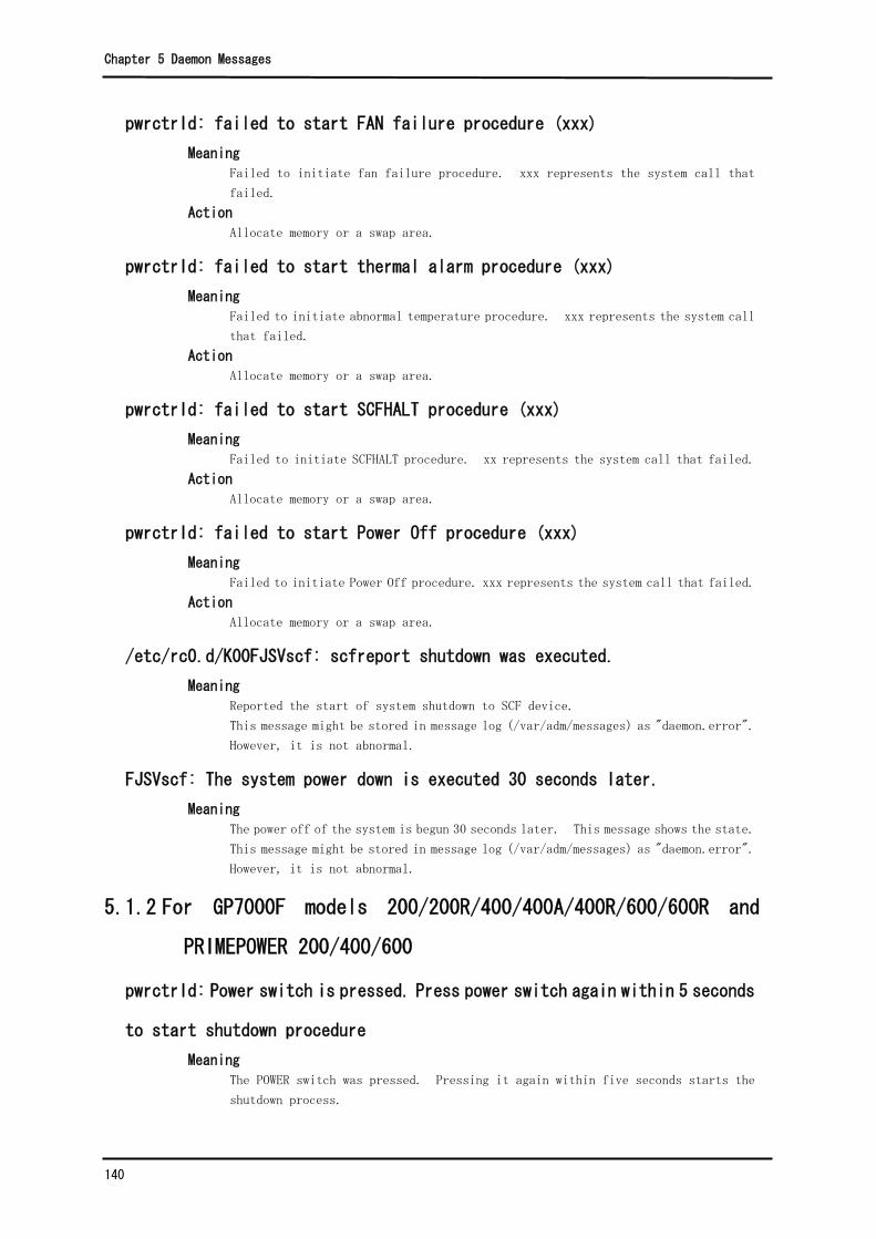
Chapter 5 Daemon Messages
pwrctrld: failed to start FAN failure procedure (xxx)
Meaning
Failed to initiate fan failure procedure. xxx represents the system call that
failed.
Action
Allocate memory or a swap area.
pwrctrld: failed to start thermal alarm procedure (xxx)
Meaning
Failed to initiate abnormal temperature procedure. xxx represents the system call
that failed.
Action
Allocate memory or a swap area.
pwrctrld: failed to start SCFHALT procedure (xxx)
Meaning
Failed to initiate SCFHALT procedure. xx represents the system call that failed.
Action
Allocate memory or a swap area.
pwrctrld: failed to start Power Off procedure (xxx)
Meaning
Failed to initiate Power Off procedure. xxx represents the system call that failed.
Action
Allocate memory or a swap area.
/etc/rc0.d/K00FJSVscf: scfreport shutdown was executed.
Meaning
Reported the start of system shutdown to SCF device.
This message might be stored in message log (/var/adm/messages) as "daemon.error".
However, it is not abnormal.
FJSVscf: The system power down is executed 30 seconds later.
Meaning
The power off of the system is begun 30 seconds later. This message shows the state.
This message might be stored in message log (/var/adm/messages) as "daemon.error".
However, it is not abnormal.
5.1.2 For GP7000F models 200/200R/400/400A/400R/600/600R and
PRIMEPOWER 200/400/600
pwrctrld: Power switch is pressed. Press power switch again within 5 seconds
to start shutdown procedure
Meaning
The POWER switch was pressed. Pressing it again within five seconds starts the
shutdown process.
140
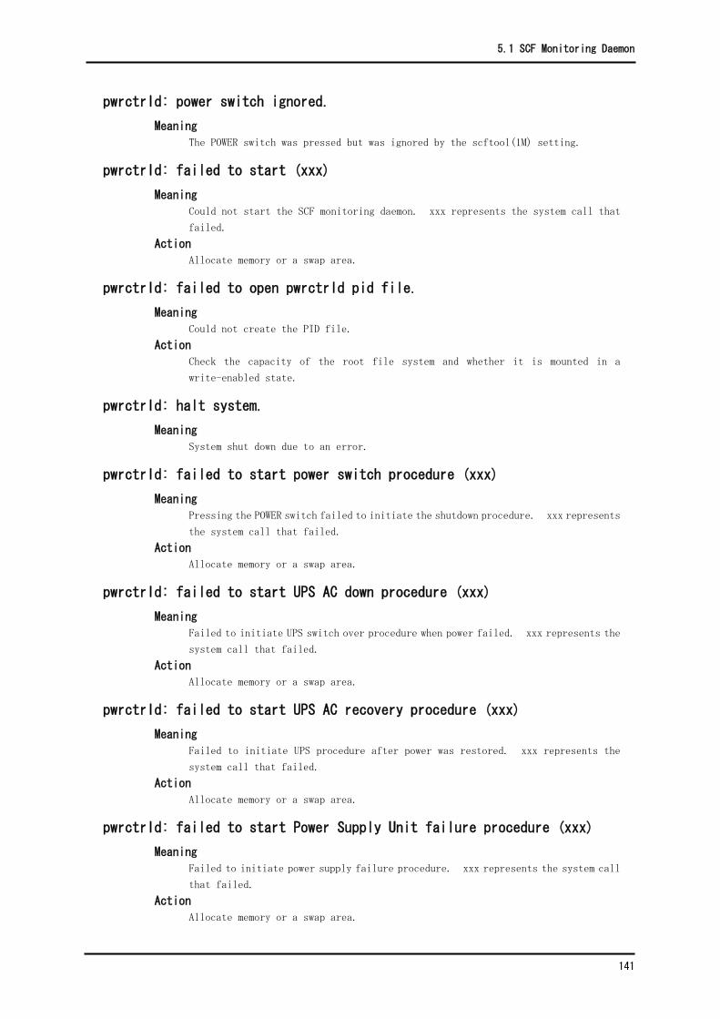
5.1 SCF Monitoring Daemon
pwrctrld: power switch ignored.
Meaning
The POWER switch was pressed but was ignored by the scftool(1M) setting.
pwrctrld: failed to start (xxx)
Meaning
Could not start the SCF monitoring daemon. xxx represents the system call that
failed.
Action
Allocate memory or a swap area.
pwrctrld: failed to open pwrctrld pid file.
Meaning
Could not create the PID file.
Action
Check the capacity of the root file system and whether it is mounted in a
write-enabled state.
pwrctrld: halt system.
Meaning
System shut down due to an error.
pwrctrld: failed to start power switch procedure (xxx)
Meaning
Pressing the POWER switch failed to initiate the shutdown procedure. xxx represents
the system call that failed.
Action
Allocate memory or a swap area.
pwrctrld: failed to start UPS AC down procedure (xxx)
Meaning
Failed to initiate UPS switch over procedure when power failed. xxx represents the
system call that failed.
Action
Allocate memory or a swap area.
pwrctrld: failed to start UPS AC recovery procedure (xxx)
Meaning
Failed to initiate UPS procedure after power was restored. xxx represents the
system call that failed.
Action
Allocate memory or a swap area.
pwrctrld: failed to start Power Supply Unit failure procedure (xxx)
Meaning
Failed to initiate power supply failure procedure. xxx represents the system call
that failed.
Action
Allocate memory or a swap area.
141
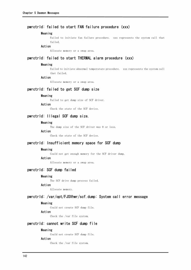
Chapter 5 Daemon Messages
pwrctrld: failed to start FAN failure procedure (xxx)
Meaning
Failed to initiate fan failure procedure. xxx represents the system call that
failed.
Action
Allocate memory or a swap area.
pwrctrld: failed to start THERMAL alarm procedure (xxx)
Meaning
Failed to initiate abnormal temperature procedure. xxx represents the system call
that failed.
Action
Allocate memory or a swap area.
pwrctrld: failed to get SCF dump size
Meaning
Failed to get dump size of SCF driver.
Action
Check the state of the SCF device.
pwrctrld: Illegal SCF dump size.
Meaning
The dump size of the SCF driver was 0 or less.
Action
Check the state of the SCF device.
pwrctrld: Insufficient memory space for SCF dump
Meaning
Could not get enough memory for the SCF driver dump.
Action
Allocate memory or a swap area.
pwrctrld: SCF dump failed
Meaning
The SCF drive dump process failed.
Action
Allocate memory.
pwrctrld: /var/opt/FJSVhwr/scf.dump: System call error message
Meaning
Could not create SCF dump file.
Action
Check the /var file system.
pwrctrld: cannot write SCF dump file
Meaning
Could not create SCF dump file.
Action
Check the /var file system.
142

5.1 SCF Monitoring Daemon
pwrctrld: failed to start SCFHALT procedure (xxx)
Meaning
Failed to initiate SCFHALT procedure. xx represents the system call that failed.
Action
Allocate memory or a swap area.
pwrctrld: failed to start RCI Power Off procedure (xxx)
Meaning
Failed to initiate RCI Power Off procedure. xxx represents the system call that
failed.
Action
Allocate memory or a swap area.
pwrctrld: failed to start Power Off procedure (xxx)
Meaning
Failed to initiate Power Off procedure. xxx represents the system call that failed.
Action
Allocate memory or a swap area.
pwrctrld: failed to open /var/opt/FJSVhwr/pwrctrld.lock
Meaning
Could not open the /var/opt/FJSVhwr/pwrctrld.lock file.
Action
Check the /var/opt/FJSVhwr/pwrctrld.lock file.
pwrctrld: SCF daemon is already running.
Meaning
SCF daemon is already running.
pwrctrld: lockf() failed
Meaning
Failed to get the file to be locked by lockf function.
Action
Check the /var/opt/FJSVhwr/pwrctrld.lock file.
/etc/rc0.d/K00FJSVscf: scfreport shutdown was executed.
Meaning
Reported the start of system shutdown to SCF device.
This message might be stored in message log (/var/adm/messages) as "daemon.error".
However, it is not abnormal.
FJSVscf: The system power down is executed 30 seconds later.
Meaning
The power off of the system is begun 30 seconds later. This message shows the state.
This message might be stored in message log (/var/adm/messages) as "daemon.error".
However, it is not abnormal.
143
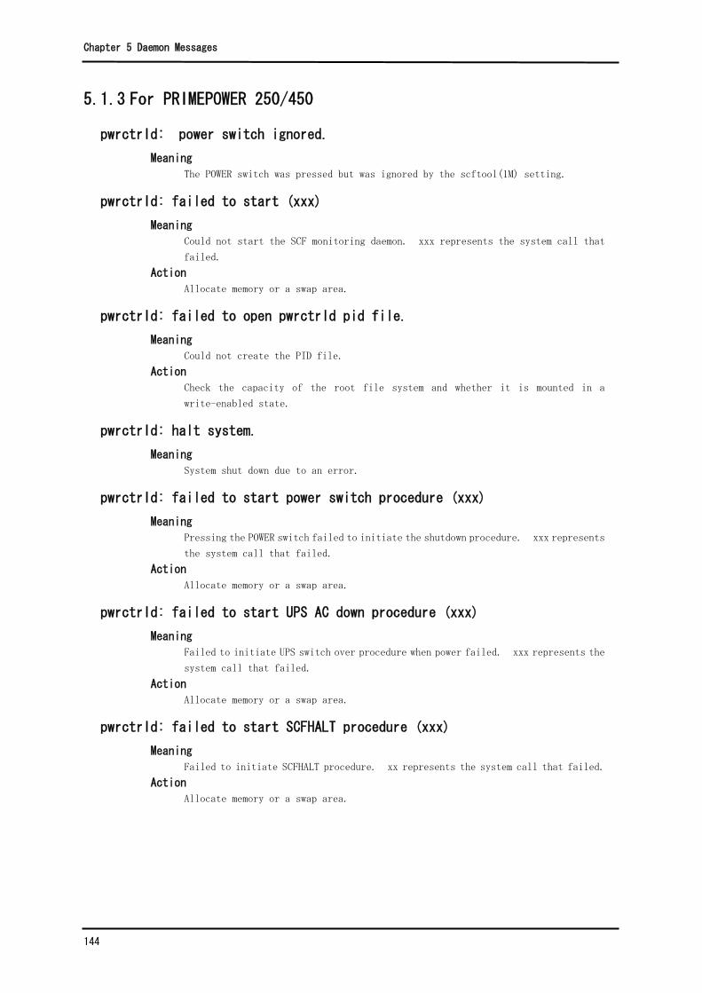
Chapter 5 Daemon Messages
5.1.3 For PRIMEPOWER 250/450
pwrctrld: power switch ignored.
Meaning
The POWER switch was pressed but was ignored by the scftool(1M) setting.
pwrctrld: failed to start (xxx)
Meaning
Could not start the SCF monitoring daemon. xxx represents the system call that
failed.
Action
Allocate memory or a swap area.
pwrctrld: failed to open pwrctrld pid file.
Meaning
Could not create the PID file.
Action
Check the capacity of the root file system and whether it is mounted in a
write-enabled state.
pwrctrld: halt system.
Meaning
System shut down due to an error.
pwrctrld: failed to start power switch procedure (xxx)
Meaning
Pressing the POWER switch failed to initiate the shutdown procedure. xxx represents
the system call that failed.
Action
Allocate memory or a swap area.
pwrctrld: failed to start UPS AC down procedure (xxx)
Meaning
Failed to initiate UPS switch over procedure when power failed. xxx represents the
system call that failed.
Action
Allocate memory or a swap area.
pwrctrld: failed to start SCFHALT procedure (xxx)
Meaning
Failed to initiate SCFHALT procedure. xx represents the system call that failed.
Action
Allocate memory or a swap area.
144

5.1 SCF Monitoring Daemon
pwrctrld: Power failure was detected. Waiting power to be supplied for n
second(s). RCI addr = 0xXXX(0xYYY)
Meaning
Power down occurred. 0xXXX represents the RCI address of UPS. When the dual power
feed configuration is defined, 0xYYY represents the RCI address of UPS pairs.
Action
Check the UPS.
pwrctrld: Power is supplied. The system keeps services on. RCI addr =
0xXXX(0xYYY)
Meaning
Power was restored. 0xXXX represents the RCI address of UPS. When the dual power
feed configuration is defined, 0xYYY represents the address of UPS pairs.
pwrctrld: failed to start SHUTDOWN procedure (xxx)
Meaning
Failed to initiate SHUTDOWN procedure. xxx represents the system call that failed.
Action
Allocate memory or a swap area.
pwrctrld: failed to start RCI-POFF procedure (xxx)
Meaning
Failed to initiate RCI power down procedure. xxx represents the system call that
failed.
Action
Allocate memory or a swap area.
pwrctrld: failed to start Power Supply Unit failure procedure (xxx)
Meaning
Failed to initiate power supply unit failure procedure. xxx represents the system
call that failed.
Action
Allocate memory or a swap area.
pwrctrld: failed to start FAN failure procedure (xxx)
Meaning
Failed to initiate FAN failure procedure. xxx represents the system call that
failed.
Action
Allocate memory or a swap area.
pwrctrld: failed to start THERMAL alarm procedure (xxx)
Meaning
Failed to initiate THERMAL alarm procedure. xxx represents the system call that
failed.
Action
Allocate memory or a swap area.
145
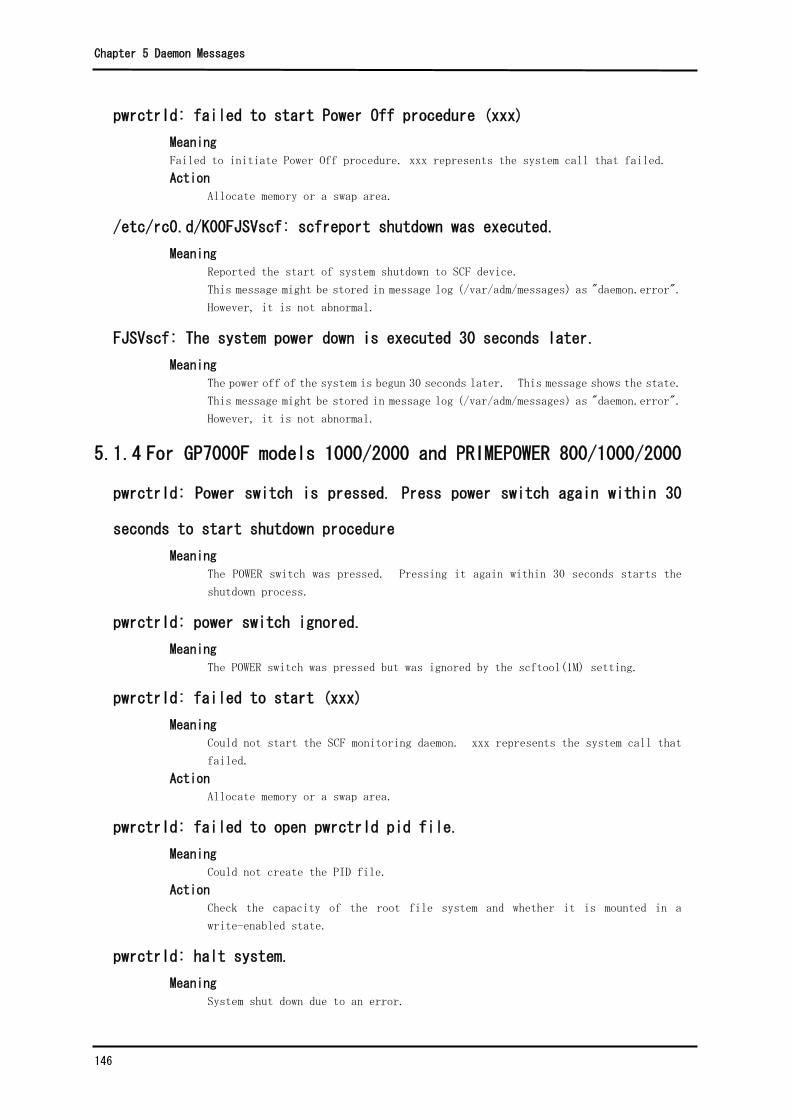
Chapter 5 Daemon Messages
pwrctrld: failed to start Power Off procedure (xxx)
Meaning
Failed to initiate Power Off procedure. xxx represents the system call that failed.
Action
Allocate memory or a swap area.
/etc/rc0.d/K00FJSVscf: scfreport shutdown was executed.
Meaning
Reported the start of system shutdown to SCF device.
This message might be stored in message log (/var/adm/messages) as "daemon.error".
However, it is not abnormal.
FJSVscf: The system power down is executed 30 seconds later.
Meaning
The power off of the system is begun 30 seconds later. This message shows the state.
This message might be stored in message log (/var/adm/messages) as "daemon.error".
However, it is not abnormal.
5.1.4 For GP7000F models 1000/2000 and PRIMEPOWER 800/1000/2000
pwrctrld: Power switch is pressed. Press power switch again within 30
seconds to start shutdown procedure
Meaning
The POWER switch was pressed. Pressing it again within 30 seconds starts the
shutdown process.
pwrctrld: power switch ignored.
Meaning
The POWER switch was pressed but was ignored by the scftool(1M) setting.
pwrctrld: failed to start (xxx)
Meaning
Could not start the SCF monitoring daemon. xxx represents the system call that
failed.
Action
Allocate memory or a swap area.
pwrctrld: failed to open pwrctrld pid file.
Meaning
Could not create the PID file.
Action
Check the capacity of the root file system and whether it is mounted in a
write-enabled state.
pwrctrld: halt system.
Meaning
System shut down due to an error.
146

5.1 SCF Monitoring Daemon
pwrctrld: failed to start power switch procedure (xxx)
Meaning
Pressing the POWER switch failed to initiate the shutdown procedure. xxx represents
the system call that failed.
Action
Allocate memory or a swap area.
pwrctrld: failed to start UPS AC down procedure (xxx)
Meaning
Failed to initiate UPS switch over procedure when power failed. xxx represents the
system call that failed.
Action
Allocate memory or a swap area.
pwrctrld: failed to start SCFHALT procedure (xxx)
Meaning
Failed to initiate SCFHALT procedure. xx represents the system call that failed.
Action
Allocate memory or a swap area.
pwrctrld: Power failure was detected. Waiting power to be supplied for n
second(s). RCI addr = 0xXXX(0xYYY)
Meaning
Power down occurred. 0xXXX represents the RCI address of UPS. When the dual power
feed configuration is defined, 0xYYY represents the RCI address of UPS pairs.
Action
Check the UPS.
pwrctrld: Power is supplied. The system keeps services on. RCI addr =
0xXXX(0xYYY)
Meaning
Power was restored. 0xXXX represents the RCI address of UPS. When the dual power
feed configuration is defined, 0xYYY represents the address of UPS pairs.
pwrctrld: failed to start SHUTDOWN procedure (xxx)
Meaning
Failed to initiate SHUTDOWN procedure. xxx represents the system call that failed.
Action
Allocate memory or a swap area.
pwrctrld: failed to start RCI-POFF procedure (xxx)
Meaning
Failed to initiate RCI power down procedure. xxx represents the system call that
failed.
Action
Allocate memory or a swap area.
147

Chapter 5 Daemon Messages
/etc/rc0.d/K00FJSVscf: scfreport shutdown was executed.
Meaning
Reported the start of system shutdown to SCF device.
This message might be stored in message log (/var/adm/messages) as "daemon.error".
However, it is not abnormal.
FJSVscf: The system power down is executed 30 seconds later.
Meaning
The power off of the system is begun 30 seconds later. This message shows the state.
This message might be stored in message log (/var/adm/messages) as "daemon.error".
However, it is not abnormal.
5.1.5 For PRIMEPOWER 650/850/900/1500/2500/HPC2500
pwrctrld: power switch ignored.
Meaning
The POWER switch was pressed but was ignored by the scftool(1M) setting.
pwrctrld: failed to start (xxx)
Meaning
Could not start the SCF monitoring daemon. xxx represents the system call that
failed.
Action
Allocate memory or a swap area.
pwrctrld: failed to open pwrctrld pid file.
Meaning
Could not create the PID file.
Action
Check the capacity of the root file system and whether it is mounted in a
write-enabled state.
pwrctrld: halt system.
Meaning
System shut down due to an error.
pwrctrld: failed to start power switch procedure (xxx)
Meaning
Pressing the POWER switch failed to initiate the shutdown procedure. xxx represents
the system call that failed.
Action
Allocate memory or a swap area.
pwrctrld: failed to start UPS AC down procedure (xxx)
Meaning
Failed to initiate UPS switch over procedure when power failed. xxx represents the
system call that failed.
Action
Allocate memory or a swap area.
148

5.1 SCF Monitoring Daemon
pwrctrld: failed to start SCFHALT procedure (xxx)
Meaning
Failed to initiate SCFHALT procedure. xx represents the system call that failed.
Action
Allocate memory or a swap area.
pwrctrld: Power failure was detected. Waiting power to be supplied for n
second(s). RCI addr = 0xXXX(0xYYY)
Meaning
Power down occurred. 0xXXX represents the RCI address of UPS. When the dual power
feed configuration is defined, 0xYYY represents the RCI address of UPS pairs.
Action
Check the UPS.
pwrctrld: Power is supplied. The system keeps services on. RCI addr =
0xXXX(0xYYY)
Meaning
Power was restored. 0xXXX represents the RCI address of UPS. When the dual power
feed configuration is defined, 0xYYY represents the address of UPS pairs.
pwrctrld: failed to start SHUTDOWN procedure (xxx)
Meaning
Failed to initiate SHUTDOWN procedure. xxx represents the system call that failed.
Action
Allocate memory or a swap area.
pwrctrld: failed to start RCI-POFF procedure (xxx)
Meaning
Failed to initiate RCI power down procedure. xxx represents the system call that
failed.
Action
Allocate memory or a swap area.
pwrctrld: failed to start Power Supply Unit failure procedure (xxx)
Meaning
Failed to initiate power supply unit failure procedure. xxx represents the system
call that failed.
Action
Allocate memory or a swap area.
pwrctrld: failed to start FAN failure procedure (xxx)
Meaning
Failed to initiate FAN failure procedure. xxx represents the system call that
failed.
Action
Allocate memory or a swap area.
149
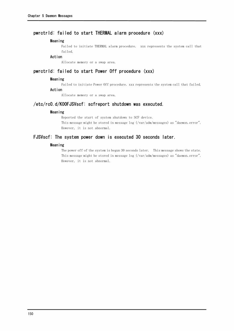
Chapter 5 Daemon Messages
pwrctrld: failed to start THERMAL alarm procedure (xxx)
Meaning
Failed to initiate THERMAL alarm procedure. xxx represents the system call that
failed.
Action
Allocate memory or a swap area.
pwrctrld: failed to start Power Off procedure (xxx)
Meaning
Failed to initiate Power Off procedure. xxx represents the system call that failed.
Action
Allocate memory or a swap area.
/etc/rc0.d/K00FJSVscf: scfreport shutdown was executed.
Meaning
Reported the start of system shutdown to SCF device.
This message might be stored in message log (/var/adm/messages) as "daemon.error".
However, it is not abnormal.
FJSVscf: The system power down is executed 30 seconds later.
Meaning
The power off of the system is begun 30 seconds later. This message shows the state.
This message might be stored in message log (/var/adm/messages) as "daemon.error".
However, it is not abnormal.
150

Chapter 6 Command Messages
This chapter gives the meaning of messages displayed by command that SCF driver offers.
It also describes what to do when you get error messages.
The system call error messages listed below are described by man -s 2 Intro.
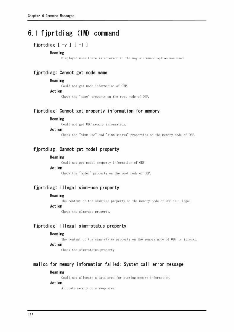
Chapter 6 Command Messages
6.1 fjprtdiag (1M) command fjprtdiag [ -v ] [ -l ]
Meaning
Displayed when there is an error in the way a command option was used.
fjprtdiag: Cannot get node name
Meaning
Could not get node information of OBP.
Action
Check the "name" property on the root node of OBP.
fjprtdiag: Cannot get property information for memory
Meaning
Could not get OBP memory information.
Action
Check the "simm-use" and "simm-status" properties on the memory node of OBP.
fjprtdiag: Cannot get model property
Meaning
Could not get model property information of OBP.
Action
Check the "model" property on the root node of OBP.
fjprtdiag: Illegal simm-use property
Meaning
The content of the simm-use property on the memory node of OBP is illegal.
Action
Check the simm-use property.
fjprtdiag: Illegal simm-status property
Meaning
The content of the simm-status property on the memory node of OBP is illegal.
Action
Check the simm-status property.
malloc for memory information failed: System call error message
Meaning
Could not allocate a data area for storing memory information.
Action
Allocate memory or a swap area.
152
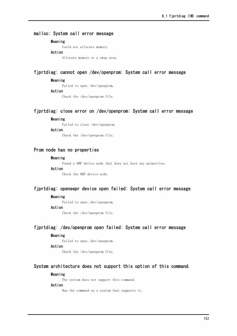
6.1 fjprtdiag (1M) command
malloc: System call error message
Meaning
Could not allocate memory.
Action
Allocate memory or a swap area.
fjprtdiag: cannot open /dev/openprom: System call error message
Meaning
Failed to open /dev/openprom.
Action
Check the /dev/openprom file.
fjprtdiag: close error on /dev/openprom: System call error message
Meaning
Failed to close /dev/openprom.
Action
Check the /dev/openprom file.
Prom node has no properties
Meaning
Found a OBP device node that does not have any properties.
Action
Check the OBP device node.
fjprtdiag: openeepr device open failed: System call error message
Meaning
Failed to open /dev/openprom.
Action
Check the /dev/openprom file.
fjprtdiag: /dev/openprom open failed: System call error message
Meaning
Failed to open /dev/openprom.
Action
Check the /dev/openprom file.
System architecture does not support this option of this command.
Meaning
The system does not support this command.
Action
Run the command on a system that supports it.
153
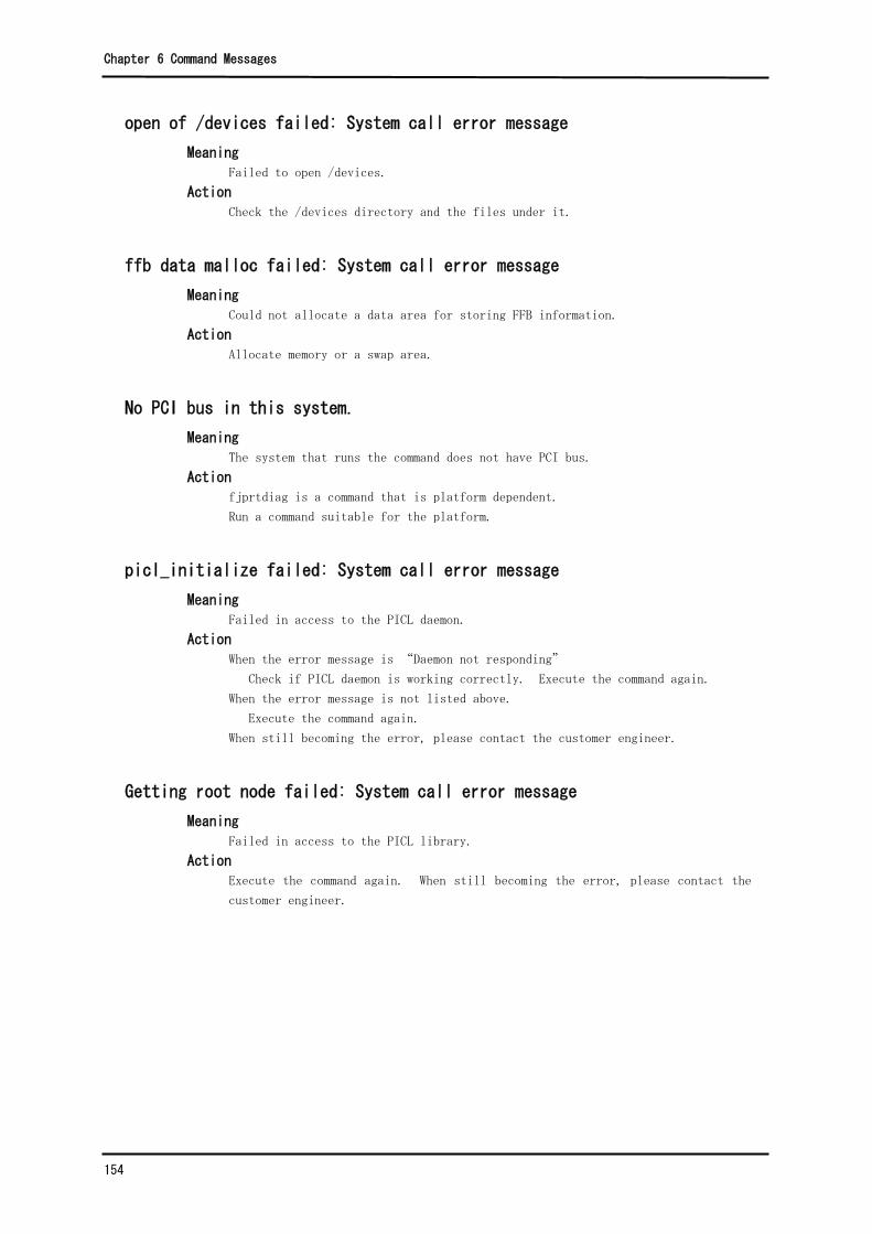
Chapter 6 Command Messages
open of /devices failed: System call error message
Meaning
Failed to open /devices.
Action
Check the /devices directory and the files under it.
ffb data malloc failed: System call error message
Meaning
Could not allocate a data area for storing FFB information.
Action
Allocate memory or a swap area.
No PCI bus in this system.
Meaning
The system that runs the command does not have PCI bus.
Action
fjprtdiag is a command that is platform dependent.
Run a command suitable for the platform.
picl_initialize failed: System call error message
Meaning
Failed in access to the PICL daemon.
Action
When the error message is “Daemon not responding”
Check if PICL daemon is working correctly. Execute the command again.
When the error message is not listed above.
Execute the command again.
When still becoming the error, please contact the customer engineer.
Getting root node failed: System call error message
Meaning
Failed in access to the PICL library.
Action
Execute the command again. When still becoming the error, please contact the
customer engineer.
154
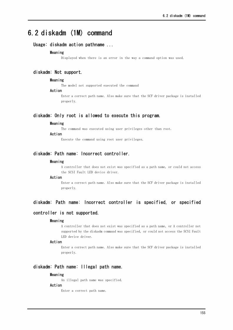
6.2 diskadm (1M) command
6.2 diskadm (1M) command Usage: diskadm action pathname ...
Meaning
Displayed when there is an error in the way a command option was used.
diskadm: Not support.
Meaning
The model not supported executed the command
Action
Enter a correct path name. Also make sure that the SCF driver package is installed
properly.
diskadm: Only root is allowed to execute this program.
Meaning
The command was executed using user privileges other than root.
Action
Execute the command using root user privileges.
diskadm: Path name: Incorrect controller.
Meaning
A controller that does not exist was specified as a path name, or could not access
the SCSI Fault LED device driver.
Action
Enter a correct path name. Also make sure that the SCF driver package is installed
properly.
diskadm: Path name: Incorrect controller is specified, or specified
controller is not supported.
Meaning
A controller that does not exist was specified as a path name, or A controller not
supported by the diskadm command was specified, or could not access the SCSI Fault
LED device driver.
Action
Enter a correct path name. Also make sure that the SCF driver package is installed
properly.
diskadm: Path name: Illegal path name.
Meaning
An illegal path name was specified.
Action
Enter a correct path name.
155

Chapter 6 Command Messages
diskadm: Path name: No such device.
Meaning
A controller that does not exist was specified as a path name.
Action
Enter a correct path name.
diskadm: /dev/FJSVhwr/fled: open() failed: System call error message
Meaning
For GP7000F model 200/200R/400/400A/400R/600/600R and PRIMEPOWER 1/200/400/600
Failed to open the Fault LED device driver.
For PRIMEPOWER 250/450/650/850/900/1500/2500/HPC2500
Failed to open the SCF driver.
Action
Make sure that the SCF driver package is installed properly.
diskadm: ioctl() --- FLED_IOC_GET_PROP failed: System call error message
Meaning
For GP7000F model 200/200R/400/400A/400R/600/600R and PRIMEPOWER 1/200/400/600
ioctl(2) to the Fault LED device driver failed and the property (led-control-0/1)
could not be read.
For PRIMEPOWER 250/450/650/850/900/1500/2500/HPC2500
ioctl(2) to the SCF driver failed and the property (led-control-0 for 79) could
not be read.
Action
Make sure that the SCF driver package is installed properly.
diskadm: ioctl() --- FLED_IOC_POWER failed: System call error message
Meaning
ioctl(2) to the Fault LED device driver failed and the write to or read from a register
failed.
Action
Make sure that the SCF driver package is installed properly.
diskadm: ioctl() --- FLED_IOC_POWER_GET failed: System call error message
Meaning
ioctl(2) to the SCF driver failed and the write to or read from a register failed.
Action
Make sure that the SCF driver package is installed properly.
diskadm: strdup() failed: System call error message
Meaning
Strdup (3C) failed.
Action
Allocate memory or a swap area.
156
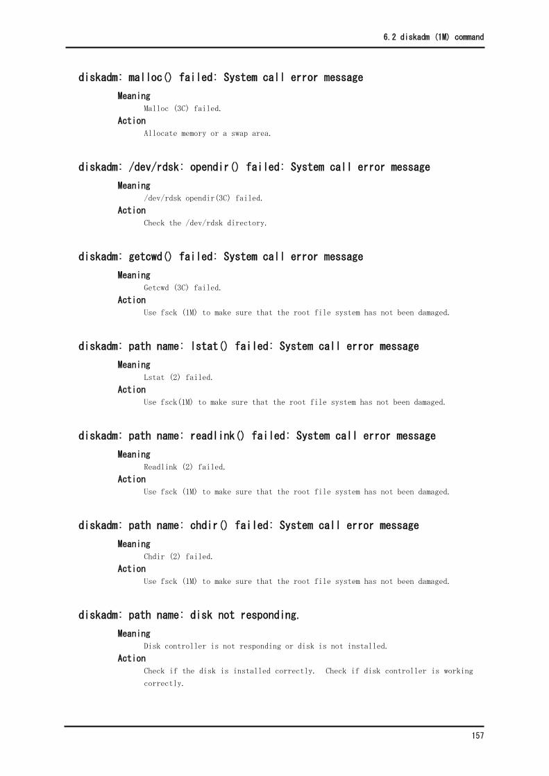
6.2 diskadm (1M) command
diskadm: malloc() failed: System call error message
Meaning
Malloc (3C) failed.
Action
Allocate memory or a swap area.
diskadm: /dev/rdsk: opendir() failed: System call error message
Meaning
/dev/rdsk opendir(3C) failed.
Action
Check the /dev/rdsk directory.
diskadm: getcwd() failed: System call error message
Meaning
Getcwd (3C) failed.
Action
Use fsck (1M) to make sure that the root file system has not been damaged.
diskadm: path name: lstat() failed: System call error message
Meaning
Lstat (2) failed.
Action
Use fsck(1M) to make sure that the root file system has not been damaged.
diskadm: path name: readlink() failed: System call error message
Meaning
Readlink (2) failed.
Action
Use fsck (1M) to make sure that the root file system has not been damaged.
diskadm: path name: chdir() failed: System call error message
Meaning
Chdir (2) failed.
Action
Use fsck (1M) to make sure that the root file system has not been damaged.
diskadm: path name: disk not responding.
Meaning
Disk controller is not responding or disk is not installed.
Action
Check if the disk is installed correctly. Check if disk controller is working
correctly.
157

Chapter 6 Command Messages
Warning: Cannot lstat file name
Meaning
File lstat (2) failed. (File name is the file under /dev/rdsk)
Action
Check the /dev/rdsk directory.
Warning: file name is not a symbolic link
Meaning
A file other than a symbolic link is in the /dev/rdsk directory.
Action
There is problem with the /dev/rdsk directory. Reboot the system using boot -r.
Warning: path name: already started, but trying again.
Meaning
The device is already booted but diskadm is trying again.
Warning: path name: already stopped, but trying again.
Meaning
The device is already stopped, but diskadm is trying again.
diskadm: /dev/FJSVhwr opendir() failed: System call error message
Meaning
/dev/FJSVhwr opendir (3C) failed.
Action
Make sure that the SCF driver package is installed properly.
diskadm: ioctl() --- SFLED_IOC_LIST failed: System call error message
Meaning
Ioctl (2) to the SCSI Fault LED device driver failed.
Action
Check the state of SCSI Fault LED device.
diskadm: ioctl() --- SFLED_IOC_OFF failed: System call error message
Meaning
Ioctl (2) to the SCSI Fault LED device driver failed.
Action
Check the state of SCSI Fault LED device.
diskadm: ioctl() --- SFLED_IOC_ON failed: System call error message
Meaning
ioctl(2) to the SCSI Fault LED device driver failed.
Action
Check the state of SCSI Fault LED device.
158

6.2 diskadm (1M) command
diskadm: /dev/FJSVhwr/sfledX: open failed: Device Busy
Meaning
Another diskadm command is being executed.
Action
Execute the command again.
diskadm: /dev/es/sesX: open failed: Device Busy
Meaning
Another diskadm command is being executed, or failed to open the SES device driver.
Action
Execute the command again.
diskadm: /dev/openprom: open() failed: System call error message
Meaning
Failed to open /dev/openprom.
Action
Check the /dev/openprom file.
diskadm: ioctl() --- OPROMNXTPROP failed: System call error message
Meaning
Ioctl (2) to the /dev/openprom failed.
Action
Check the /dev/openprom file.
diskadm: ioctl() --- OPROMGETPROP failed: System call error message
Meaning
Ioctl (2) to the /dev/openprom failed.
Action
Check the /dev/openprom file.
diskadm: ioctl() --- OPROMNEXT failed: System call error message
Meaning
Ioctl (2) to the /dev/openprom failed.
Action
Check the /dev/openprom file.
diskadm: ioctl() --- OPROMCHILD failed: System call error message
Meaning
Ioctl (2) to the /dev/openprom failed.
Action
Check the /dev/openprom file.
159
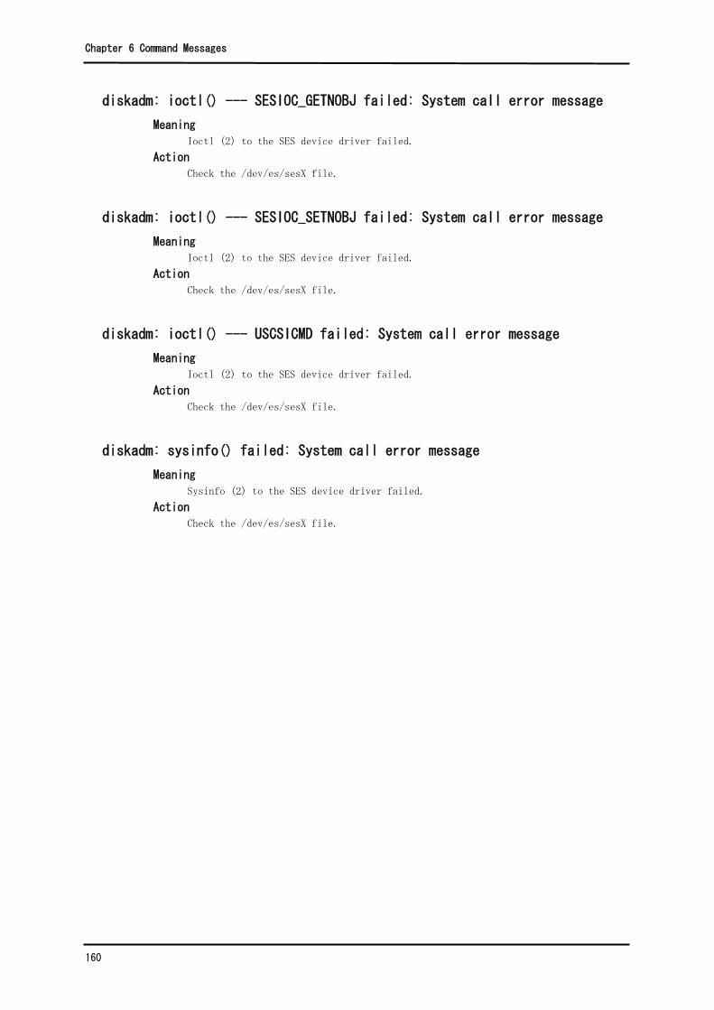
Chapter 6 Command Messages
diskadm: ioctl() --- SESIOC_GETNOBJ failed: System call error message
Meaning
Ioctl (2) to the SES device driver failed.
Action
Check the /dev/es/sesX file.
diskadm: ioctl() --- SESIOC_SETNOBJ failed: System call error message
Meaning
Ioctl (2) to the SES device driver failed.
Action
Check the /dev/es/sesX file.
diskadm: ioctl() --- USCSICMD failed: System call error message
Meaning
Ioctl (2) to the SES device driver failed.
Action
Check the /dev/es/sesX file.
diskadm: sysinfo() failed: System call error message
Meaning
Sysinfo (2) to the SES device driver failed.
Action
Check the /dev/es/sesX file.
160
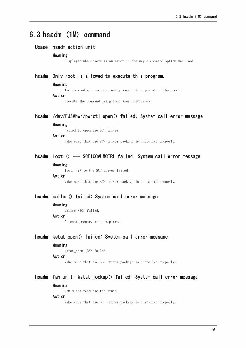
6.3 hsadm (1M) command
6.3 hsadm (1M) command Usage: hsadm action unit
Meaning
Displayed when there is an error in the way a command option was used.
hsadm: Only root is allowed to execute this program.
Meaning
The command was executed using user privileges other than root.
Action
Execute the command using root user privileges.
hsadm: /dev/FJSVhwr/pwrctl open() failed: System call error message
Meaning
Failed to open the SCF driver.
Action
Make sure that the SCF driver package is installed properly.
hsadm: ioctl() --- SCFIOCALMCTRL failed: System call error message
Meaning
Ioctl (2) to the SCF driver failed.
Action
Make sure that the SCF driver package is installed properly.
hsadm: malloc() failed: System call error message
Meaning
Malloc (3C) failed.
Action
Allocate memory or a swap area.
hsadm: kstat_open() failed: System call error message
Meaning
kstat_open (3K) failed.
Action
Make sure that the SCF driver package is installed properly.
hsadm: fan_unit: kstat_lookup() failed: System call error message
Meaning
Could not read the fan state.
Action
Make sure that the SCF driver package is installed properly.
161

Chapter 6 Command Messages
hsadm: power_unit: kstat_lookup() failed: System call error message
Meaning
Could not read power supply state.
Action
Make sure that the SCF driver package is installed properly.
hsadm: kstat_read() failed: System call error message
Meaning
kstat_read (3K) failed.
Action
Make sure that the SCF driver package is installed properly.
162
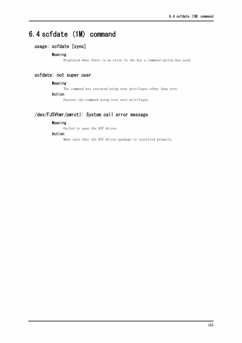
6.4 scfdate (1M) command
6.4 scfdate (1M) command usage: scfdate [sync]
Meaning
Displayed when there is an error in the way a command option was used.
scfdate: not super user
Meaning
The command was executed using user privileges other than root.
Action
Execute the command using root user privileges.
/dev/FJSVhwr/pwrctl: System call error message
Meaning
Failed to open the SCF driver.
Action
Make sure that the SCF driver package is installed properly.
163
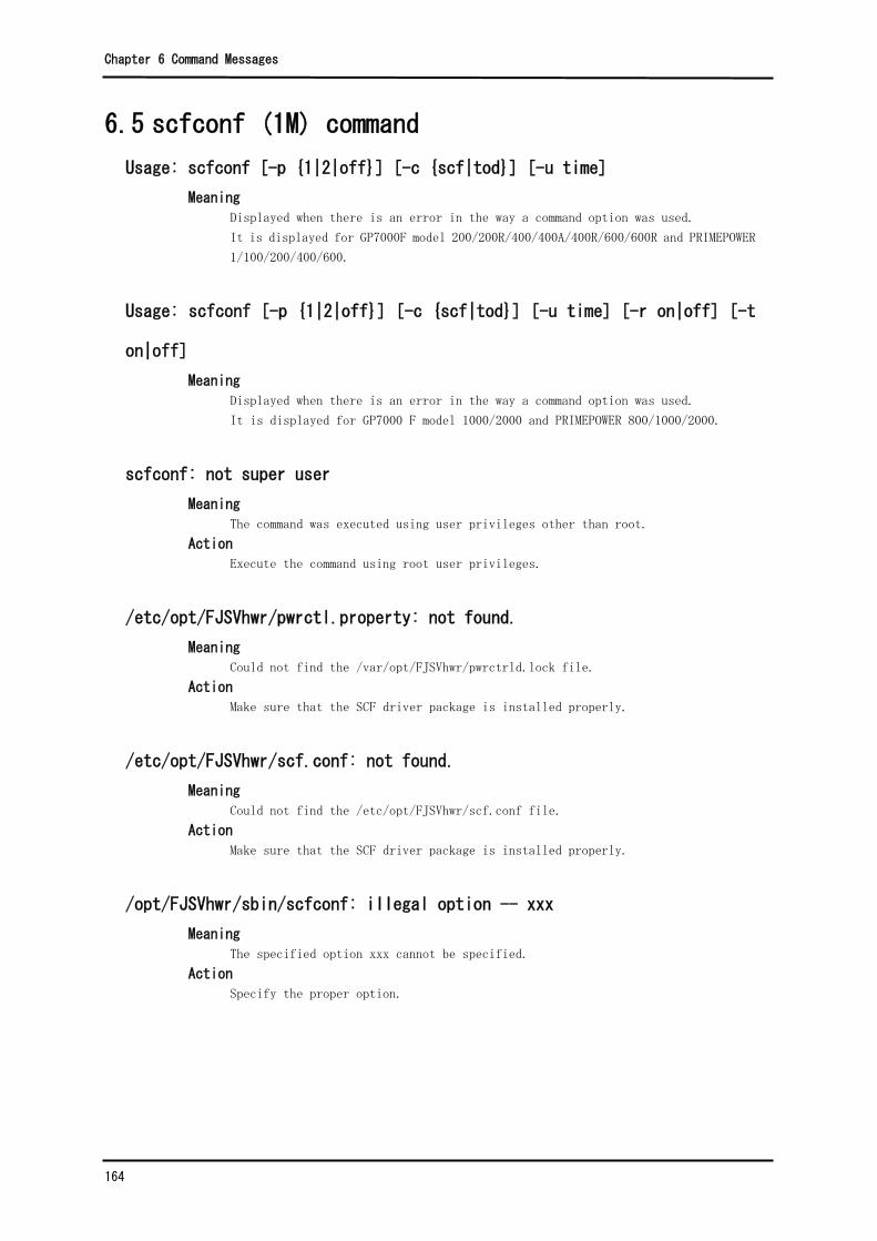
Chapter 6 Command Messages
6.5 scfconf (1M) command Usage: scfconf [-p {1|2|off}] [-c {scf|tod}] [-u time]
Meaning
Displayed when there is an error in the way a command option was used.
It is displayed for GP7000F model 200/200R/400/400A/400R/600/600R and PRIMEPOWER
1/100/200/400/600.
Usage: scfconf [-p {1|2|off}] [-c {scf|tod}] [-u time] [-r on|off] [-t
on|off]
Meaning
Displayed when there is an error in the way a command option was used.
It is displayed for GP7000 F model 1000/2000 and PRIMEPOWER 800/1000/2000.
scfconf: not super user
Meaning
The command was executed using user privileges other than root.
Action
Execute the command using root user privileges.
/etc/opt/FJSVhwr/pwrctl.property: not found.
Meaning
Could not find the /var/opt/FJSVhwr/pwrctrld.lock file.
Action
Make sure that the SCF driver package is installed properly.
/etc/opt/FJSVhwr/scf.conf: not found.
Meaning
Could not find the /etc/opt/FJSVhwr/scf.conf file.
Action
Make sure that the SCF driver package is installed properly.
/opt/FJSVhwr/sbin/scfconf: illegal option -- xxx
Meaning
The specified option xxx cannot be specified.
Action
Specify the proper option.
164
6.6 scftool (1M) command
6.6 scftool (1M) command scftool: not super user
Meaning
The command was executed using user privileges other than root.
Action
Execute the command using root user privileges.
"SCF Clock" mode is selected.
The system clock is now based on "SCF Clock".
In this mode, when you change the "System default" clock (by using "date"
comannd etc.),
you need to synchronize "SCF Clock" by the following command:
# scfdate sync
Meaning
The SCF high-resolution clock setting was changed to "SCF Clock."
When the menu is operated by scftool with GP7000 F model
200/200R/400/400A/400R/600/600R and PRIMEPOWER1/100/200/400/600, it is displayed.
165

Chapter 6 Command Messages
6.7 scf2tod (1M) command usage: scf2tod
Meaning
Displayed when there is an error in the way a command option was used.
166
6.8 srambackup (1M) command
6.8 srambackup (1M) command srambackup: not super user
Meaning
The command was executed using user privileges other than root.
Action
Execute the command using root user privileges.
WARNING: SCF SRAM contents recovered, check SCF battery please
Meaning
The data backed up by the SCF battery was lost, and instead was restored from a backup.
Action
After the motherboard is changed, this message might be displayed. In this case,
the action is unnecessary.
If displayed by not listed above, check the SCF battery.
/dev/FJSVhwr/pwrctl: System call error message
Meaning
Could not access the SCF driver.
Action
Make sure that the SCF driver package is installed properly.
File name: System call error message
Meaning
Could not access the SCF SRAM backup file.
Action
Check the file system containing the SCF SRAM backup file.
can't rename file name 1 to file name 2
Meaning
You cannot change the name of the SCF SRAM backup file.
Action
Check the file system containing the SCF SRAM backup file.
srambackup: out of memory
Meaning
There is not enough memory.
Action
Allocate memory or a swap area.
167
Chapter 6 Command Messages
6.9 scferrlog (1M) command /dev/FJSVhwr/pwrctl: System call error message
Meaning
Could not access the SCF driver.
Action
Make sure that the SCF driver package is installed properly.
File name: System call error message
Meaning
Could not open the file for creating the SCF error log.
Action
Check the file system containing the file for creating the SCF error log.
scferrlog: write: System call error message
Meaning
Write (2) failed on the file for creating the SCF error log.
Action
Check the file system containing the file for creating the SCF error log.
168

6.10 scfpwrlog (1M) command
6.10 scfpwrlog (1M) command File name: System call error message
Meaning
Could not open the file for creating the power log.
Action
Check the file system containing the file for creating the power log.
/dev/FJSVhwr/pwrctl: System call error message
Meaning
Could not access the SCF driver.
Action
Make sure that the SCF driver package is installed properly.
scfpwrlog: fstat: System call error message
Meaning
Fstat (2) failed on the file for creating the power log.
Action
Check the file system containing the file for creating the power log.
lseek: System call error message
Meaning
Lseek (2) failed on the file for creating the power log.
Action
Check the file system containing the file for creating the power log.
read: System call error message
Meaning
Read (2) failed on the file for creating the power log.
Action
Check the file system containing the file for creating the power log.
scfpwrlog: write: System call error message
Meaning
Write (2) failed on the file for creating the power log.
Action
Check the file system containing the file for creating the power log.
169
Chapter 6 Command Messages
6.11 scfreport (1M) command Usage: scfreport [ running | shutdown ]
Meaning
Displayed when there is an error in the way a command option was used.
scfreport: not super user
Meaning
The command was executed using user privileges other than root.
Action
Execute the command using root user privileges.
/dev/FJSVhwr/pwrctl: System call error message
/dev/FJSVhwr/pwrctl2: System call error message
Meaning
Could not access the SCF driver.
Action
Make sure that the SCF driver package is installed properly.
/etc/rc0.d/K00FJSVscf: scfreport shutdown was executed.
Meaning
Reported the start of system shutdown to SCF device.
In the case where power down occurred after this message was displayed, the system
will not boot when power is restored.
This message might be stored in message log (/var/adm/messages) as "daemon.error".
However, it is not abnormal.
170

6.12 lcdecho (1M) command
6.12 lcdecho (1M) command /dev/FJSVhwr/pwrctl: System call error message
Meaning
Could not access the SCF driver.
Action
Make sure that the SCF driver package is installed properly.
171

Chapter 6 Command Messages
6.13 scfwatchdog (1M) command Usage: scfwatchdog [ enable | disable ]
Meaning
Displayed when there is an error in the way a command option was used.
scfwatchdog: not super user
Meaning
The command was executed using user privileges other than root.
Action
Execute the command using root user privileges.
scfwatchdog: System call error message
Meaning
Could not access the SCF driver.
Action
Make sure that the SCF driver package is installed properly.
172
6.14 voltconf (1M) command
6.14 voltconf (1M) command Usage: voltconf [-h|-l|-n]
-h: VH, -l: VL,-n: VN
Meaning
Displayed when there is an error in the way a command option was used.
/dev/FJSVhwr/pwrctl: System call error message
Meaning
Could not access /dev/FJSVhwr/pwrctl device.
Action
Check the /dev/FJSVhwr/pwrctl file.
Make sure that the SCF driver package is installed properly.
ioctl: System call error message
Meaning
ioctl of the SCF driver failed.
Action
Make sure that the SCF driver package is installed properly.
173
Chapter 6 Command Messages
6.15 rciinfo (1M) command rciinfo: failed to open /dev/FJSVhwr/rcictl
rciinfo: failed to open /dev/FJSVhwr/rcictl2
Meaning
Failed to open the SCF driver.
Action
Make sure that the SCF driver package is installed properly.
rciinfo: ioctl() failed
Meaning
Could not access the SCF driver.
Action
Check the state of the SCF device.
rciinfo: malloc() failed
Meaning
Could not allocate memory.
Action
Allocate memory or a swap area.
174
6.16 rcinodeadm (1M) command
6.16 rcinodeadm (1M) command usage: rcinodeadm address { enable | disable }
Meaning
Displayed when there is an error in the way a command option was used.
rcinodeadm: failed to open /dev/FJSVhwr/rcictl
Meaning
Failed to open SCF driver.
Action
Make sure that the SCF driver package is installed properly.
rcinodeadm: invalid rci address
Meaning
Invalid RCI address was specified.
Action
Enter a correct RCI address.
rcinodeadm: ioctl() failed
Meaning
Could not access the SCF driver.
Action
Check the state of the SCF device.
rcinodeadm: RCI xxx does not exist
Meaning
The RCI device that address has specified RCI address XXX does not exist.
Action
Enter a correct RCI address.
175
Chapter 6 Command Messages
6.17 rcihello (1M) command usage: rcihello { on | off } [ address ]
Meaning
Displayed when there is an error in the way a command option was used.
rcihello: failed to open /dev/FJSVhwr/rcictl
Meaning
Failed to open SCF driver.
Action
Make sure that the SCF driver package is installed properly.
rcihello: invalid rci address
Meaning
Invalid RCI address was specified.
Action
Enter a correct RCI address.
rcihello: RCI xxx does not exist
Meaning
The RCI device that has specified RCI address XXX does not exist.
Action
Enter a correct RCI address.
rcihello: ioctl() failed
Meaning
Could not access the SCF driver.
Action
Check the state of the SCF device.
rcihello: ioctl() failed. could not set led status on RCI(addr = xx)
Meaning
Could not set led status on the RCI device of the address displayed.
Action
Check the RCI device of the address displayed.
176
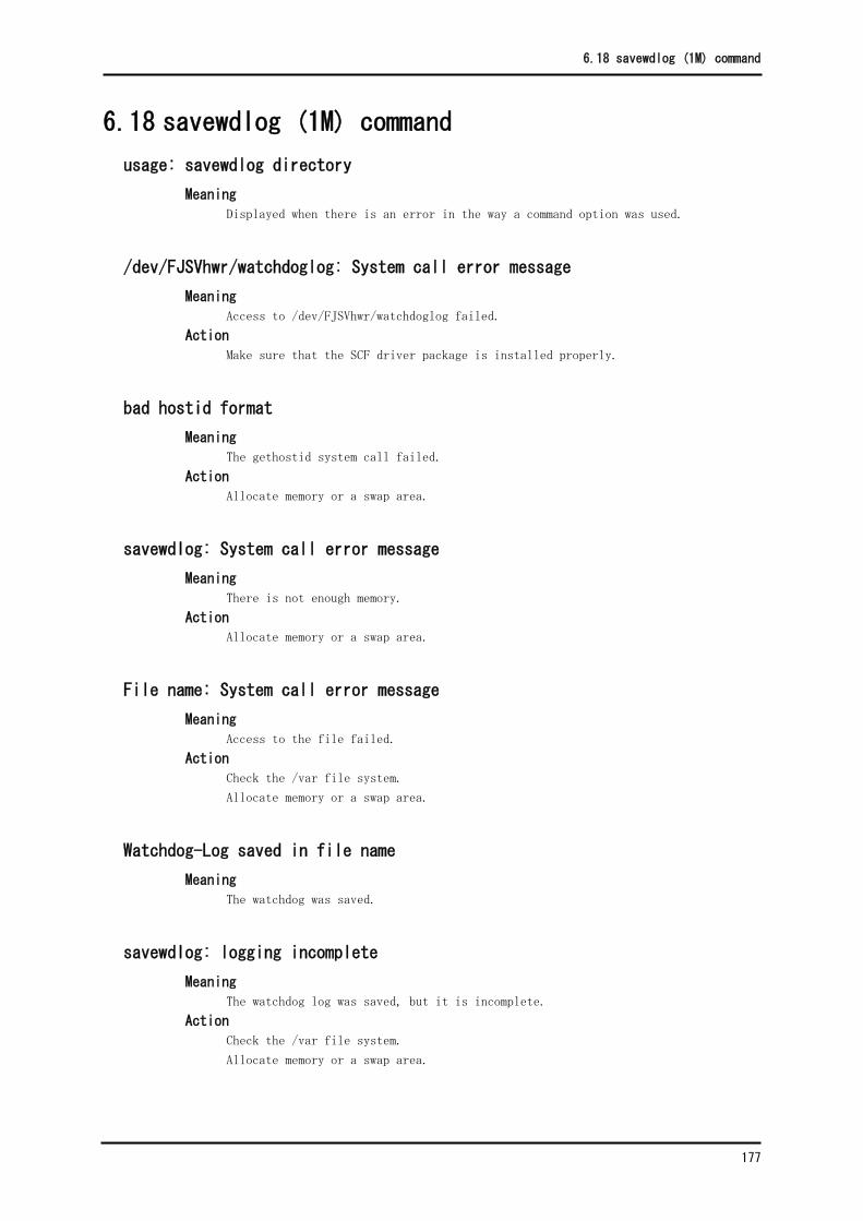
6.18 savewdlog (1M) command
6.18 savewdlog (1M) command usage: savewdlog directory
Meaning
Displayed when there is an error in the way a command option was used.
/dev/FJSVhwr/watchdoglog: System call error message
Meaning
Access to /dev/FJSVhwr/watchdoglog failed.
Action
Make sure that the SCF driver package is installed properly.
bad hostid format
Meaning
The gethostid system call failed.
Action
Allocate memory or a swap area.
savewdlog: System call error message
Meaning
There is not enough memory.
Action
Allocate memory or a swap area.
File name: System call error message
Meaning
Access to the file failed.
Action
Check the /var file system.
Allocate memory or a swap area.
Watchdog-Log saved in file name
Meaning
The watchdog was saved.
savewdlog: logging incomplete
Meaning
The watchdog log was saved, but it is incomplete.
Action
Check the /var file system.
Allocate memory or a swap area.
177

Chapter 6 Command Messages
File name: fopen() failed
Meaning
Failed to open the file.
Action
Check the /var file system.
File name: fclose() failed
Meaning
Failed to close the file.
Action
Check the /var file system.
File name: fputs() failed
Meaning
Write to the file failed.
Action
Check the /var file system.
178

6.19 scfhltlog (1M) command
6.19 scfhltlog (1M) command /dev/FJSVhwr/pwrctl: System call error message
Meaning
Access to the SCF driver failed.
Action
Make sure that the SCF driver package is installed properly.
scfhltlog: System call error message
Meaning
Failed to allocate memory.
Action
Allocate memory or a swap area.
scfhltlog: Removing the log in SCF failed
Meaning
Failed to delete the hard halt log.
Action
Check the state of the SCF device.
Hard Halt Log was saved in file name
The log had occurred at time
Meaning
The hardware halt log that had occurred at 'time' was retrieved and stored in 'file
name'.
scfhltlog: file close failed
Meaning
Failed to close the file.
Action
Check the state of the /var file system.
scfhltlog: bounds file open failed
Meaning
Failed to open /var/opt/FJSVhwr/wdlog/bounds file.
Action
Check the state of the /var file system.
scfhltlog: bounds write failed
Meaning
Failed to write /var/opt/FJSVhwr/wdlog/bounds file.
Action
Check the state of the /var file system.
179

Chapter 6 Command Messages
usage: scfhltlog [ -h ] [ -n ] [ -f device ] [ -d directory ]
Meaning
Displayed when there is an error in the way a command option was used.
scfhltlog: Halt log was not saved correctly on SCF.
Meaning
The hardware halt log exists on the SCF device, but it was not saved correctly.
Action
Check the state of the SCF device.
180

6.20 scfnotice (1M) command
6.20 scfnotice (1M) command Usage: scfnotice pfail
Meaning
Displayed when there is an error in the way a command option was used.
scfnotice: not super user
Meaning
The command was executed using user privileges other than root.
Action
Execute the command using root user privileges.
scfnotice: failed to open /dev/FJSVhwr/rasctl
scfnotice: failed to open /dev/FJSVhwr/rasctl2
Meaning
Failed to open the SCF driver.
Action
Make sure that the SCF driver package is installed properly.
scfnotice: ioctl() failed
Meaning
Could not access the SCF driver.
Action
Make sure that the SCF driver package is installed properly.
181

Chapter 6 Command Messages
6.21 rciopecall (1M) command Usage: rciopecall: address { disp | on callNo | off callNo }
Meaning
Displayed when there is an error in the way a command option was used.
rciopecall: failed to open /dev/FJSVhwr/rcictl
rciopecall: failed to open /dev/FJSVhwr/rcictl2
Meaning
Failed to open the SCF driver.
Action
Make sure that the SCF driver package is installed properly.
rciopecall: not super user
Meaning
The command was executed using user privileges other than root.
Action
Execute the command using root user privileges.
rciopecall: ioctl() failed
Meaning
Could not access the SCF driver.
Action
Make sure that the SCF driver package is installed properly.
rciopecall: invalid rci address
Meaning
Invalid RCI address.
Action
Check the RCI address.
rciopecall: invalid callNo
Meaning
Invalid callNo.
Action
Check the callNo.
rciopecall: malloc() failed
Meaning
malloc (3C) failed.
Action
Allocate memory or a swap area.
182
6.21 rciopecall (1M) command
rciopecall: RCI xxx does not exist
Meaning
The RCI device that has specified RCI address XXX does not exist.
Action
Check the specified RCI device.
183

Chapter 6 Command Messages
6.22 nodeled(1M) command Usage: nodeled [-led check] –status
nodeled [-led check] -mode on | blink | off
Meaning
Displayed when there is an error in the way a command option was used.
nodeled: not super user
Meaning
The command was executed using user privileges other than root.
Action
Execute the command using root user privileges.
nodeled: cannot open /dev/FJSVhwr/rasctl: System call error message
Meaning
Failed to open the SCF driver.
Action
Make sure that the SCF driver package is installed properly.
nodeled: ioctl() failed: System call error message
Meaning
Could not access the SCF driver.
Action
Make sure that the SCF driver package is installed properly.
184
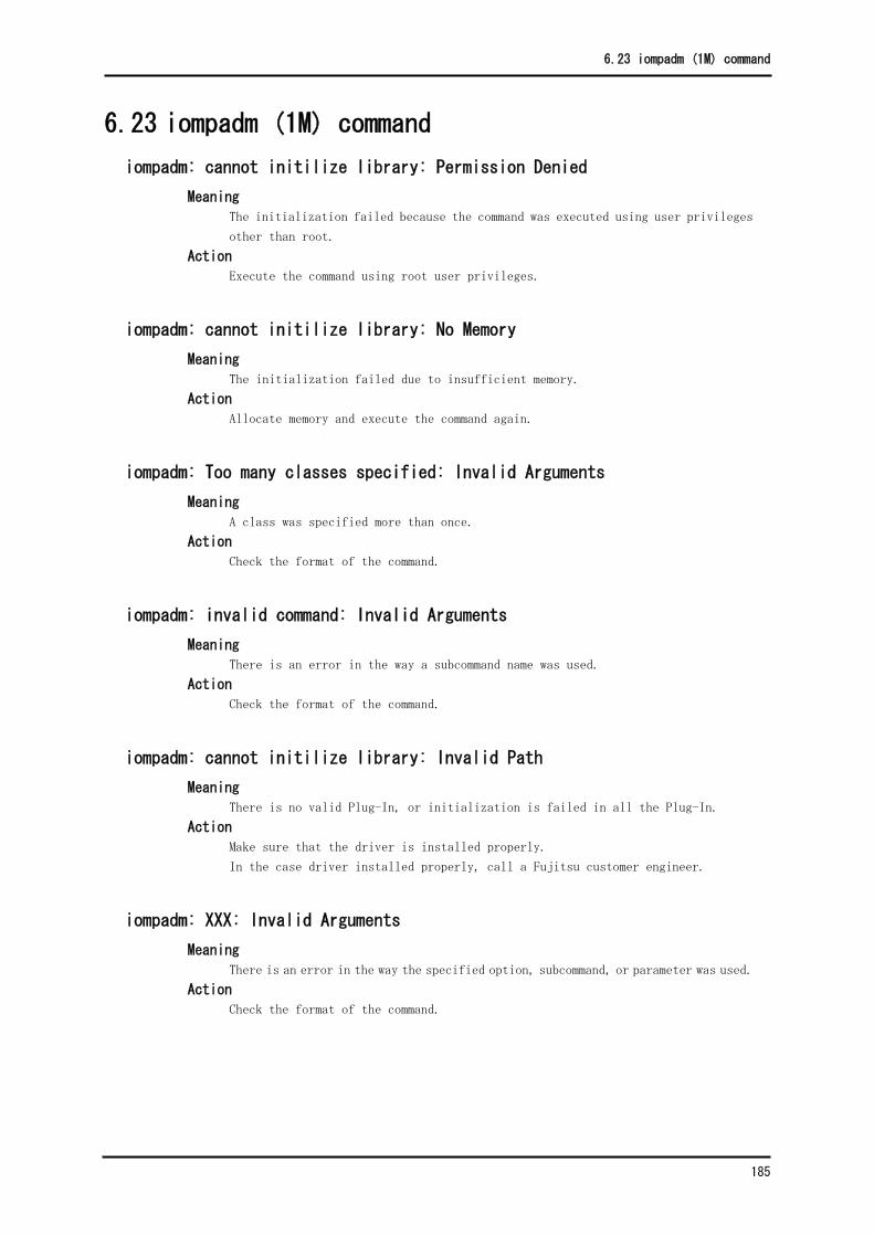
6.23 iompadm (1M) command
6.23 iompadm (1M) command iompadm: cannot initilize library: Permission Denied
Meaning
The initialization failed because the command was executed using user privileges
other than root.
Action
Execute the command using root user privileges.
iompadm: cannot initilize library: No Memory
Meaning
The initialization failed due to insufficient memory.
Action
Allocate memory and execute the command again.
iompadm: Too many classes specified: Invalid Arguments
Meaning
A class was specified more than once.
Action
Check the format of the command.
iompadm: invalid command: Invalid Arguments
Meaning
There is an error in the way a subcommand name was used.
Action
Check the format of the command.
iompadm: cannot initilize library: Invalid Path
Meaning
There is no valid Plug-In, or initialization is failed in all the Plug-In.
Action
Make sure that the driver is installed properly.
In the case driver installed properly, call a Fujitsu customer engineer.
iompadm: XXX: Invalid Arguments
Meaning
There is an error in the way the specified option, subcommand, or parameter was used.
Action
Check the format of the command.
185

Chapter 6 Command Messages
iompadm: XXX: No Memory
Meaning
Insufficient memory occurred during the command execution.
Action
Allocate memory and execute the command again.
iompadm: XXX: Invalid Path Number
Meaning
The path was added/deleted to the same class by another process during the command
execution.
Action
Execute the command again after completing the job of the other process.
iompadm: XXX: Invalid Path
Meaning
There is an error in the way the path name was specified in the parameter.
Action
Specify a valid path name.
iompadm: XXX: Too Many Path
Meaning
The paths specified in the parameter exceeded the maximum number.
Action
Make sure that the driver is installed properly.
In the case driver installed properly, call a Fujitsu customer engineer.
iompadm: XXX: Not Implemented
Meaning
The specified subcommand dose not support on this product.
Action
Check an available subcommand.
iompadm: XXX: Class not Found
Meaning
Could not find a class that corresponds to specified communication path name.
Action
Check the specified communication path name.
iompadm: XXX: Not Supported
Meaning
Entered the state, which is not supported by this class.
Action
Check an available subcommand.
186
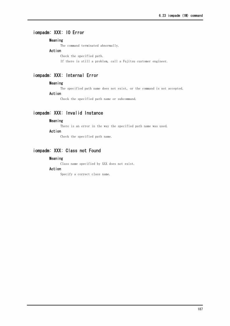
6.23 iompadm (1M) command
iompadm: XXX: IO Error
Meaning
The command terminated abnormally.
Action
Check the specified path.
If there is still a problem, call a Fujitsu customer engineer.
iompadm: XXX: Internal Error
Meaning
The specified path name does not exist, or the command is not accepted.
Action
Check the specified path name or subcommand.
iompadm: XXX: Invalid Instance
Meaning
There is an error in the way the specified path name was used.
Action
Check the specified path name.
iompadm: XXX: Class not Found
Meaning
Class name specified by XXX does not exist.
Action
Specify a correct class name.
187
Chapter 6 Command Messages
6.24 DR Connection Script message Can't disconnect for last SCFC
Meaning
Disconnect cannot be executed because of the last SCFC.
iompadm command abnomal end action=XX path=YY
Meaning
iompadm command error.
XX represents the subcommand of the iompadm command.
YY represents the path name.
Action
Check the status of the displayed path.
If there is still a problem, call a Fujitsu customer engineer.
188
Index
Index
C
Changing PATH.............................................................. 8 Command Messages.................................................... 151 CUI controlling SCF features........................................ 38
D
Daemon Messages....................................................... 138 diskadm (1M)................................................................ 34 display pathname........................................................ 34 Driver Messages............................................................ 62
G
GUI controlling SCF features........................................ 36
H
help subcommand.......................................................... 60 hsadm (1M) ................................................................... 32
I
ident subcommand ........................................................ 58 info subcommand .......................................................... 54 iompadm (1M) .............................................................. 53 iompadm subcommand ................................................. 54
K
kernel parameter of SCF driver ..................................... 15
L
LCD Panel....................................................................... 6 LED lamp........................................................................ 5
M
Main Cabinet................................................................... 1 MODE Switch................................................................. 4 Multipath control command .......................................... 53
N
Notes............................................................................. 12
P
POWER Switch Settings................................................11 Prints system diagnostic information ............................ 25 probe subcommand ....................................................... 58 Processing when UPS is connected,
and power failure occurred ....................................... 14 prtdiag (1M)............................................................ 25, 61
R
rcihello (1M)................................................................. 44 rciinfo (1M) .................................................................. 46 rcinodeadm (1M) .......................................................... 47 rciopecall (1M) ............................................................. 49 recover subcommand .................................................... 58 Reports operator call on units connected via RCI ......... 49
S
scfconf (1M) ................................................................. 38 scfdate (1M).................................................................. 41 scftool (1M) .................................................................. 36 Server Setup.................................................................... 8 Shutdown ........................................................................ 3 start subcommand ......................................................... 59 status subcommand ....................................................... 57
T
Troubleshooting ............................................................ 13
U
UPS Operation Time..................................................... 12 Using Panel Controls ...................................................... 4
V
version subcommand .................................................... 59