Enabling Switches - IDEC · HE1B Series Enabling Switches 404 Overview X Series E-Stops Door...
20
Table of Contents Automation & Sensing - Pg. 1 Safety - Pg. 315 Switching & Controls - Pg. 439 Index - Pg. 911 For more information on this product family, visit our website. Additional resources include: • New and updated product information • Downloadable software demos & upgrades • Part configuration tool & cross reference • Online stock check & ordering • IDEC field sales & distributor search • Online literature request • Downloadable manuals & CAD drawings • Manufacturer’s suggested retail price list • Product training schedule & locations • Advertising & trade show schedules • Press releases & FAQs Overview X Series E-Stops Door Interlock Switches Enabling Switches Barriers As-Interface Safety at Work www.idec.com/safety Safety Selection Guide ........................................... 403 HE1B Series Basic Enabling Switch............ 404 HE2B Series Redundant (Double) Basic Enabling Switch .......................................... 407 HE3B Series Pushbutton Enabling Switch .. 410 HE5B Series Pushbutton Enabling Switch .. 413 HE1G Series Grip Style Enabling Switch .... 416 General Information .................................... 419 Enabling Switches
-
Upload
nguyendieu -
Category
Documents
-
view
219 -
download
0
Transcript of Enabling Switches - IDEC · HE1B Series Enabling Switches 404 Overview X Series E-Stops Door...
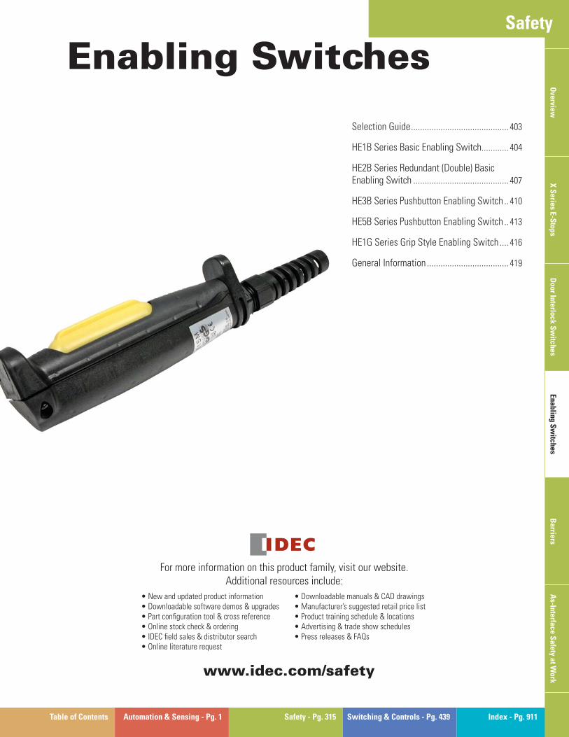
Table of Contents Automation & Sensing - Pg. 1 Safety - Pg. 315 Switching & Controls - Pg. 439 Index - Pg. 911
For more information on this product family, visit our website. Additional resources include:
• New and updated product information • Downloadable software demos & upgrades • Part confi guration tool & cross reference • Online stock check & ordering • IDEC fi eld sales & distributor search • Online literature request
• Downloadable manuals & CAD drawings • Manufacturer’s suggested retail price list • Product training schedule & locations • Advertising & trade show schedules • Press releases & FAQs
Overview
X S
eries E-Stops
Door Interlock S
witches
Enabling Sw
itchesB
arriersA
s-Interface Safety at W
orkwww.idec.com/safety
Safety
Selection Guide ........................................... 403
HE1B Series Basic Enabling Switch............ 404
HE2B Series Redundant (Double) Basic Enabling Switch .......................................... 407
HE3B Series Pushbutton Enabling Switch .. 410
HE5B Series Pushbutton Enabling Switch .. 413
HE1G Series Grip Style Enabling Switch .... 416
General Information .................................... 419
Enabling Switches
Overview Enabling Switches
402 www.idec.com
Ove
rvie
wX
Ser
ies
E-S
tops
Doo
r In
terl
ock
Sw
itch
es E
nabl
ing
Sw
itch
esB
arri
res
AS
-Int
erfa
ce S
afet
y at
Wor
k
Enabling “Dead Man” Switches
What is an enabling switch?
An enabling switch is a 3-position (OFF-ON-OFF) switch to allow a machine operation only when the switch is lightly pressed and held in the middle position (position 2). Because it disables machine operation when released (position 1) or further depressed (position 3) by a panicked operator, the safety of operators is ensured.
Because operators use pendants in hazardous environments performing teach-ing, system changeover, and maintenance of robots, they must have protection against unpredictable motion of robots, and therefore teach pendants are equipped with 3-position enabling switches.
Selection GuideEnabling Switches
403USA: 800-262-IDEC Canada: 888-317-IDEC
Overview
X S
eries E-Stops
Door Interlock S
witches
Enabling Sw
itchesB
arriersA
S-Interface S
afety at Work
Selection Guide
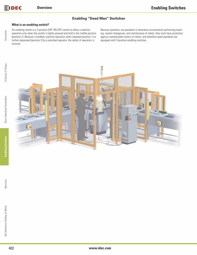
Enabling Switches
Series Model HE1B HE2B HE3B HE5B HE1G
Appearance
Page 404 407 410 413 416
Description Basic Switch Redundant Basic Switch 16mm Panel Mount 16mm Round Enabling Switch Grip Switch
Maximum Contacts 1NO DPDT/DPDT, 2NC/DPDT, 4NC DPDT DPDT DPDT, 1NC/DPDT, 2NC
Application Example
Teaching Pendant Back of Teaching Pendant
Enabling Switch
HE1B Enabling Switch Movement
3 Position Enabling SwitchPosition 1 - Normal position - Contact OpenPosition 2 - Push half way - Contact ClosedPosition 3 - Push all the way - Contact Open
When releasing switch from position 3 back to position 1, the switch will not enter the ON state.
For information on the Teaching Pendant visit
www.idec.com/oi/pendant
HE1B Series Enabling Switches
404 www.idec.com
Ove
rvie
wX
Ser
ies
E-S
tops
Doo
r In
terl
ock
Sw
itch
es E
nabl
ing
Sw
itch
esB
arri
res
AS
-Int
erfa
ce S
afet
y at
Wor
k
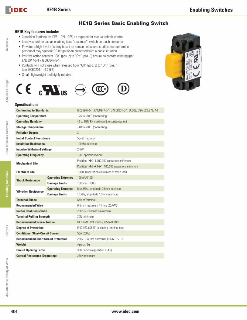
HE1B Series Basic Enabling Switch
HE1B Key features include:3 position funtionality (OFF – ON –OFF) as required for manual robotic control
Ideally suited for use as enabling (aka “deadman”) switch on teach pendants
Provides a high level of safety based on human behavioral studies that determine personnel may squeeze OR let go when presented with a panic situation
Positive action contacts “On” (pos. 2) to “Off” (pos. 3) ensure no contact welding (per EN60947-5-1 / IEC60947-5-1)
Contacts will not close when released from “Off” (pos. 3) to “Off” (pos. 1) (per IEC60204-1; 9.2.5.8)
Small, lightweight and highly reliable
•
•
•
•
•
•
Specifi cations
Conforming to Standards IEC60947-5-1, EN60947-5-1, JIS C8201-5-1, UL508, CSA C22.2 No 14
Operating Temperature –25 to +60˚C (no freezing)
Operating Humidity 45 to 85% RH maximum (no condensation)
Storage Temperature –40 to +80˚C (no freezing)
Pollution Degree 2
Initial Contact Resistance 50mΩ maximum
Insulation Resistance 100MΩ minimum
Impulse Withstand Voltage 2.5kV
Operating Frequency 1200 operations/hour
Mechanical LifePosition 1‡2: 1,000,000 operations minimum
Position 1‡2‡3‡1: 100,000 operations minimum
Electrical Life 100,000 operations minimum at rated load
Shock ResistanceOperating Extremes 100m/s2 (10G)
Damage Limits 1000m/s2 (100G)
Vibration ResistanceOperating Extremes 5 to 55Hz, amplitude 0.5mm minimum
Damage Limits 16.7Hz, amplitude 1.5mm minimum
Terminal Shape Solder Terminal
Recommended Wire 0.5mm2 maximum / 1 line (20AWG)
Solder Heat Resistance 260°C / 3 seconds maximum
Terminal Pulling Strength 20N minimum
Recommended Screw Torque HE1B-M1: M3 screw / 0.5 to 0.8Nm
Degree of Protection IP40 (IEC 60529) excluding terminal part
Conditional Short-Circuit Current 50A (250V)
Recommended Short Circuit Protection 250V, 10A fast blow fuse (IEC 60127-1)
Weight Approx. 6g
Circuit Opening Force 30N minimum (position 2‡3)
Control Resistance (Operating) 250N minimum
HE1B SeriesEnabling Switches
405USA: 800-262-IDEC Canada: 888-317-IDEC
Overview
X S
eries E-Stops
Door Interlock S
witches
Enabling Sw
itchesB
arriersA
S-Interface S
afety at Work
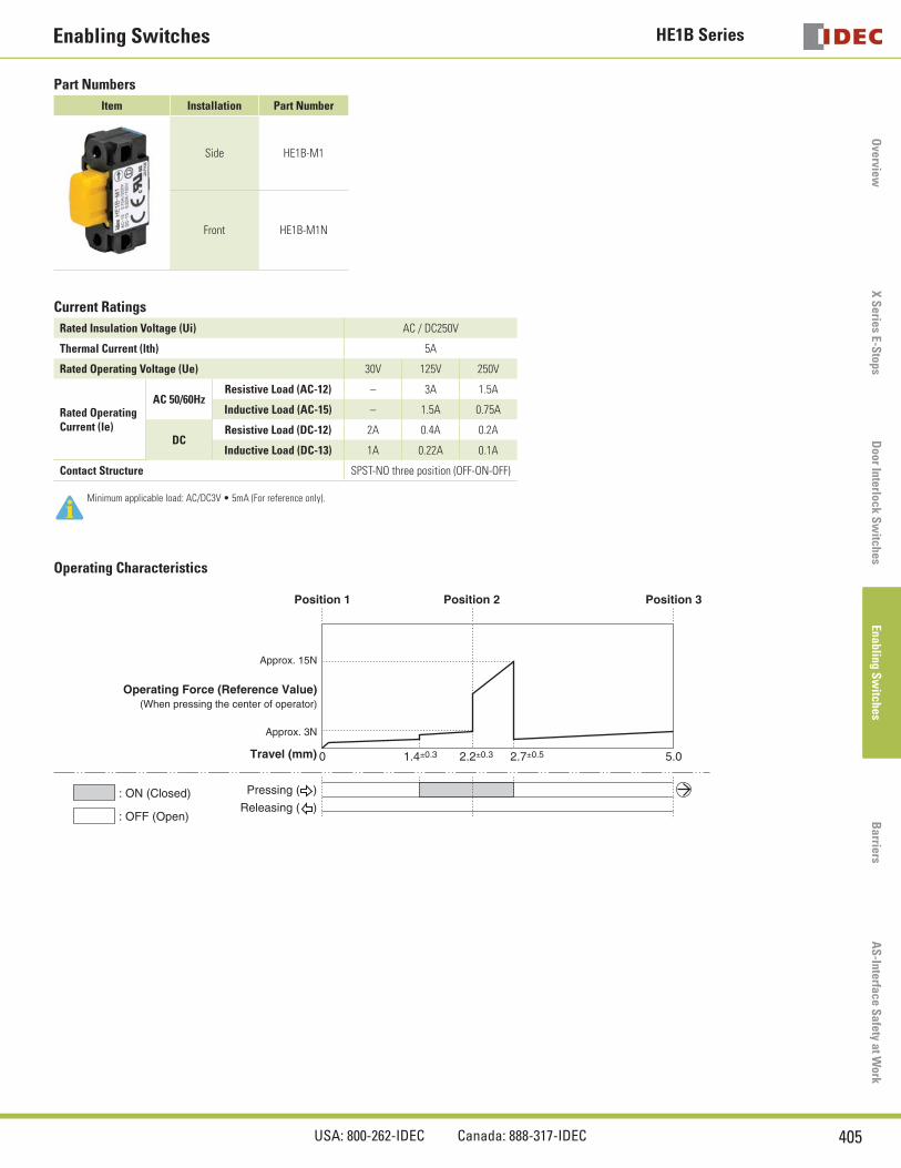
Part Numbers
Item Installation Part Number
Side HE1B-M1
Front HE1B-M1N
Current Ratings
Rated Insulation Voltage (Ui) AC / DC250V
Thermal Current (lth) 5A
Rated Operating Voltage (Ue) 30V 125V 250V
Rated OperatingCurrent (le)
AC 50/60HzResistive Load (AC-12) – 3A 1.5A
Inductive Load (AC-15) – 1.5A 0.75A
DCResistive Load (DC-12) 2A 0.4A 0.2A
Inductive Load (DC-13) 1A 0.22A 0.1A
Contact Structure SPST-NO three position (OFF-ON-OFF)
Minimum applicable load: AC/DC3V • 5mA (For reference only).
Operating Characteristics
Travel (mm)
: ON (Closed)
: OFF (Open)
Approx. 15N
Approx. 3N
0 1.4±0.3 2.2±0.3 2.7±0.5 5.0
Position 1 Position 2 Position 3
Operating Force (Reference Value)
Releasing ( )
Pressing ( )
(When pressing the center of operator)
HE1B Series Enabling Switches
406 www.idec.com
Ove
rvie
wX
Ser
ies
E-S
tops
Doo
r In
terl
ock
Sw
itch
es E
nabl
ing
Sw
itch
esB
arri
res
AS
-Int
erfa
ce S
afet
y at
Wor
k
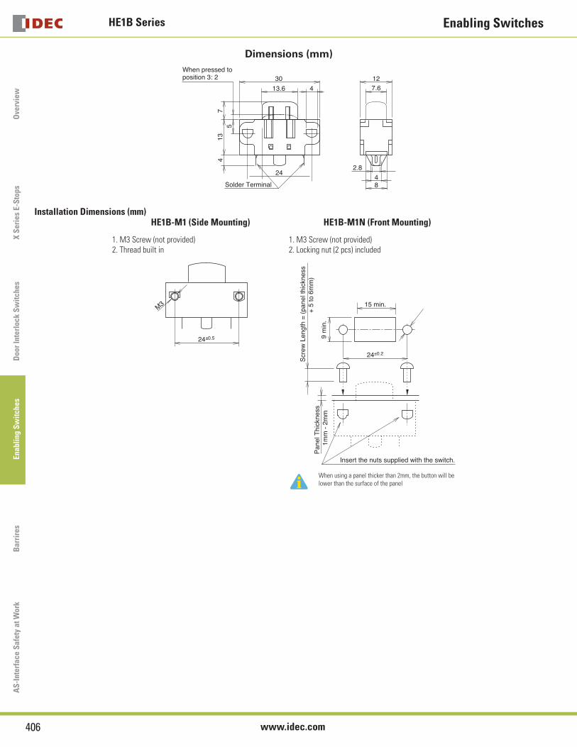
Dimensions (mm)
4
30
413
13.6
24
5
48
2.8
7.612
7
Solder Terminal
When pressed toposition 3: 2
Installation Dimensions (mm)HE1B-M1 (Side Mounting)
1. M3 Screw (not provided)2. Thread built in
HE1B-M1N (Front Mounting)
1. M3 Screw (not provided)2. Locking nut (2 pcs) included
M3
24±0.5
24±0.2
15 min.
9 m
in.
Insert the nuts supplied with the switch.
Scr
ew L
engt
h =
(pa
nel t
hick
ness
+
5 to
6m
m)
Pan
el T
hick
ness
1mm
- 2
mm
When using a panel thicker than 2mm, the button will be lower than the surface of the panel
HE2B SeriesEnabling Switches
407USA: 800-262-IDEC Canada: 888-317-IDEC
Overview
X S
eries E-Stops
Door Interlock S
witches
Enabling Sw
itchesB
arriersA
S-Interface S
afety at Work
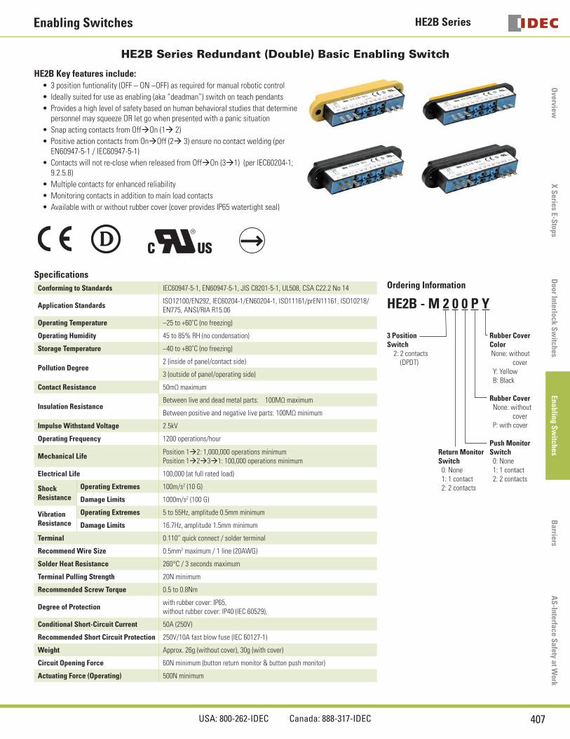
HE2B Series Redundant (Double) Basic Enabling Switch
HE2B Key features include:3 position funtionality (OFF – ON –OFF) as required for manual robotic control
Ideally suited for use as enabling (aka “deadman”) switch on teach pendants
Provides a high level of safety based on human behavioral studies that determine personnel may squeeze OR let go when presented with a panic situation
Snap acting contacts from Off‡On (1‡ 2)
Positive action contacts from On‡Off (2‡ 3) ensure no contact welding (per EN60947-5-1 / IEC60947-5-1)
Contacts will not re-close when released from Off‡On (3‡1) (per IEC60204-1; 9.2.5.8)
Multiple contacts for enhanced reliability
Monitoring contacts in addition to main load contacts
Available with or without rubber cover (cover provides IP65 watertight seal)
•
•
•
•
•
•
•
•
•
Specifi cations
Conforming to Standards IEC60947-5-1, EN60947-5-1, JIS C8201-5-1, UL508, CSA C22.2 No 14 Ordering Information
HE2B - M 2 0 0 P Y
3 Position Switch 2: 2 contacts (DPDT)
Return Monitor Switch 0: None 1: 1 contact 2: 2 contacts
Rubber Cover Color None: without cover Y: Yellow B: Black
Rubber Cover None: without cover P: with cover
Push Monitor Switch 0: None 1: 1 contact 2: 2 contacts
Application StandardsISO12100/EN292, IEC60204-1/EN60204-1, ISO11161/prEN11161, ISO10218/EN775, ANSI/RIA R15.06
Operating Temperature –25 to +60˚C (no freezing)
Operating Humidity 45 to 85% RH (no condensation)
Storage Temperature –40 to +80˚C (no freezing)
Pollution Degree2 (inside of panel/contact side)
3 (outside of panel/operating side)
Contact Resistance 50mΩ maximum
Insulation ResistanceBetween live and dead metal parts: 100MΩ maximum
Between positive and negative live parts: 100MΩ minimum
Impulse Withstand Voltage 2.5kV
Operating Frequency 1200 operations/hour
Mechanical LifePosition 1‡2: 1,000,000 operations minimumPosition 1‡2‡3‡1: 100,000 operations minimum
Electrical Life 100,000 (at full rated load)
Shock Resistance
Operating Extremes 100m/s2 (10 G)
Damage Limits 1000m/s2 (100 G)
Vibration Resistance
Operating Extremes 5 to 55Hz, amplitude 0.5mm minimum
Damage Limits 16.7Hz, amplitude 1.5mm minimum
Terminal 0.110” quick connect / solder terminal
Recommend Wire Size 0.5mm2 maximum / 1 line (20AWG)
Solder Heat Resistance 260°C / 3 seconds maximum
Terminal Pulling Strength 20N minimum
Recommended Screw Torque 0.5 to 0.8Nm
Degree of Protectionwith rubber cover: IP65, without rubber cover: IP40 (IEC 60529),
Conditional Short-Circuit Current 50A (250V)
Recommended Short Circuit Protection 250V/10A fast blow fuse (IEC 60127-1)
Weight Approx. 26g (without cover), 30g (with cover)
Circuit Opening Force 60N minimum (button return monitor & button push monitor)
Actuating Force (Operating) 500N minimum
HE2B Series Enabling Switches
408 www.idec.com
Ove
rvie
wX
Ser
ies
E-S
tops
Doo
r In
terl
ock
Sw
itch
es E
nabl
ing
Sw
itch
esB
arri
res
AS
-Int
erfa
ce S
afet
y at
Wor
k
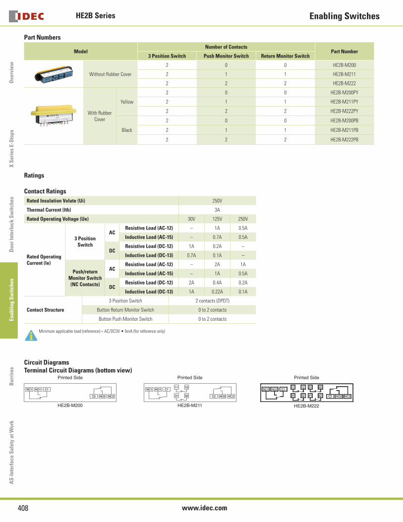
Part Numbers
ModelNumber of Contacts
Part Number3 Position Switch Push Monitor Switch Return Monitor Switch
Without Rubber Cover
2 0 0 HE2B-M200
2 1 1 HE2B-M211
2 2 2 HE2B-M222
With Rubber Cover
Yellow
2 0 0 HE2B-M200PY
2 1 1 HE2B-M211PY
2 2 2 HE2B-M222PY
Black
2 0 0 HE2B-M200PB
2 1 1 HE2B-M211PB
2 2 2 HE2B-M222PB
Ratings
Contact Ratings
Rated Insulation Volute (Ui) 250V
Thermal Current (lth) 3A
Rated Operating Voltage (Ue) 30V 125V 250V
Rated OperatingCurrent (le)
3 Position Switch
ACResistive Load (AC-12) – 1A 0.5A
Inductive Load (AC-15) – 0.7A 0.5A
DCResistive Load (DC-12) 1A 0.2A –
Inductive Load (DC-13) 0.7A 0.1A –
Push/return Monitor Switch (NC Contacts)
ACResistive Load (AC-12) – 2A 1A
Inductive Load (AC-15) – 1A 0.5A
DCResistive Load (DC-12) 2A 0.4A 0.2A
Inductive Load (DC-13) 1A 0.22A 0.1A
Contact Structure
3 Position Switch 2 contacts (DPDT)
Button Return Monitor Switch 0 to 2 contacts
Button Push Monitor Switch 0 to 2 contacts
Minimum applicable load (reference) = AC/DC3V • 5mA (for reference only)
Circuit DiagramsTerminal Circuit Diagrams (bottom view)
Printed Side
HE2B-M200
Printed Side
HE2B-M211
Printed Side
HE2B-M222
HE2B SeriesEnabling Switches
409USA: 800-262-IDEC Canada: 888-317-IDEC
Overview
X S
eries E-Stops
Door Interlock S
witches
Enabling Sw
itchesB
arriersA
S-Interface S
afety at Work
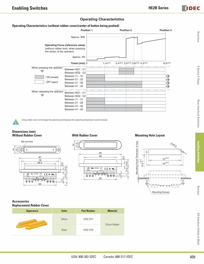
Operating Characteristics
Operating Characteristics (without rubber cover/center of button being pushed)
0
Operating Force (reference value)
Travel (mm) 1.4±0.3 2.4±0.3 3.0±0.3 6.0±0.53.6±0.5 4.2±0.5
Approx. 30N
Approx. 4N
Between NO1 - C1When pressing the operator
Between NO2 - C2Between 11 - 12Between 21 - 22Between 31 - 32Between 41 - 42
Between NO1 - C1When releasing the operator
Between NO2 - C2Between 11 - 12Between 21 - 22Between 31 - 32Between 41 - 42
: ON (closed)
: OFF (open)
Position 1 Position 2 Position 3
(without rubber boot, when pressingthe center of the operator)
Using rubber cover will change the operating load because the operating temperature would increase
Dimensions (mm)Without Rubber Cover With Rubber Cover Mounting Hole Layout
M3 nut hole
1016
14.2
769
87
13.5
5.5
5
7866.5
6.5
5
11.5
19
68
69
714
.2
90
14.8
Mou
ntin
g P
anel
Thi
ckne
ss: 6
max
.
Mounting Screws
0+0.
212
.2
±0.278
2-ø3.2
±0.270
AccessoriesReplacement Rubber Cover
Apperance Color Part Number Material
Yellow HE9Z-D2Y
Silicon Rubber
Black HE9Z-D2B
HE3B Series Enabling Switches
410 www.idec.com
Ove
rvie
wX
Ser
ies
E-S
tops
Doo
r In
terl
ock
Sw
itch
es E
nabl
ing
Sw
itch
esB
arri
res
AS
-Int
erfa
ce S
afet
y at
Wor
k
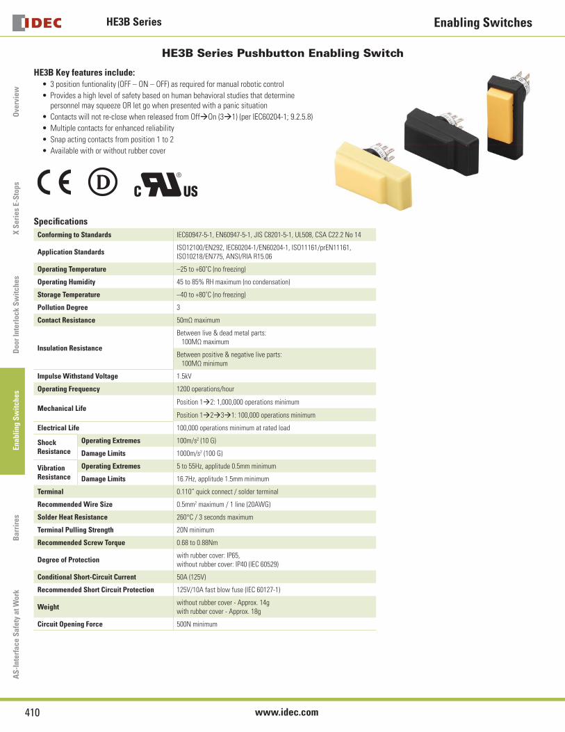
HE3B Series Pushbutton Enabling Switch
HE3B Key features include:3 position funtionality (OFF – ON – OFF) as required for manual robotic control
Provides a high level of safety based on human behavioral studies that determine personnel may squeeze OR let go when presented with a panic situation
Contacts will not re-close when released from Off‡On (3‡1) (per IEC60204-1; 9.2.5.8)
Multiple contacts for enhanced reliability
Snap acting contacts from position 1 to 2
Available with or without rubber cover
•
•
•
•
•
•
Specifi cations
Conforming to Standards IEC60947-5-1, EN60947-5-1, JIS C8201-5-1, UL508, CSA C22.2 No 14
Application StandardsISO12100/EN292, IEC60204-1/EN60204-1, ISO11161/prEN11161, ISO10218/EN775, ANSI/RIA R15.06
Operating Temperature –25 to +60˚C (no freezing)
Operating Humidity 45 to 85% RH maximum (no condensation)
Storage Temperature –40 to +80˚C (no freezing)
Pollution Degree 3
Contact Resistance 50mΩ maximum
Insulation Resistance
Between live & dead metal parts: 100MΩ maximum
Between positive & negative live parts: 100MΩ minimum
Impulse Withstand Voltage 1.5kV
Operating Frequency 1200 operations/hour
Mechanical LifePosition 1‡2: 1,000,000 operations minimum
Position 1‡2‡3‡1: 100,000 operations minimum
Electrical Life 100,000 operations minimum at rated load
Shock Resistance
Operating Extremes 100m/s2 (10 G)
Damage Limits 1000m/s2 (100 G)
Vibration Resistance
Operating Extremes 5 to 55Hz, applitude 0.5mm minimum
Damage Limits 16.7Hz, applitude 1.5mm minimum
Terminal 0.110” quick connect / solder terminal
Recommended Wire Size 0.5mm2 maximum / 1 line (20AWG)
Solder Heat Resistance 260°C / 3 seconds maximum
Terminal Pulling Strength 20N minimum
Recommended Screw Torque 0.68 to 0.88Nm
Degree of Protectionwith rubber cover: IP65, without rubber cover: IP40 (IEC 60529)
Conditional Short-Circuit Current 50A (125V)
Recommended Short Circuit Protection 125V/10A fast blow fuse (IEC 60127-1)
Weightwithout rubber cover - Approx. 14gwith rubber cover - Approx. 18g
Circuit Opening Force 500N minimum
HE3B SeriesEnabling Switches
411USA: 800-262-IDEC Canada: 888-317-IDEC
Overview
X S
eries E-Stops
Door Interlock S
witches
Enabling Sw
itchesB
arriersA
S-Interface S
afety at Work
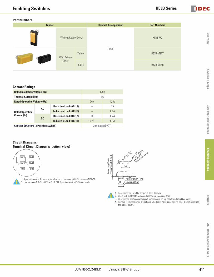
Part Numbers
Model Contact Arrangement Part Numbers
Without Rubber Cover
DPDT
HE3B-M2
With Rubber Cover
Yellow HE3B-M2PY
Black HE3B-M2PB
Contact Ratings
Rated Insulation Voltage (Ui) 125V
Thermal Current (lth) 3A
Rated Operating Voltage (Ue) 30V 125V
Rated OperatingCurrent (le)
ACResistive Load (AC-12) – 1A
Inductive Load (AC-15) – 0.7A
DCResistive Load (DC-12) 1A 0.2A
Inductive Load (DC-13) 0.7A 0.1A
Contact Structure (3 Position Switch) 2 contacts (DPDT)
Circuit DiagramsTerminal Circuit Diagrams (bottom view)
NC1 NC2
NO1
C1 C2
NO2
Mou
ntin
g P
anel
Thi
ckne
ss 0
.5 to
4
Locking RingAnti-rotation Ring
(Note)
Depth: 2.5
(Posit
ioning Hole)
0+0.2
ø3.20+0.2
ø16.2
30
1. 3 position switch: 2 contacts, terminal no. = between NO1-C1, between NO2-C22. Use between NO-C for OFF‡ On‡ OFF 3 position switch (NC is not used).
1. Recommended Lock Nut Torque: 0.68 to 0.88Nm.2. Use a lock nut tool to screw on the lock nut (see page 412).3. To retain the switches waterproof performance, do not penetrate the rubber cover.4. Remove the rubber cover projection if you do not want a positioning hole. (Do not penetrate
the rubber cover).
HE3B Series Enabling Switches
412 www.idec.com
Ove
rvie
wX
Ser
ies
E-S
tops
Doo
r In
terl
ock
Sw
itch
es E
nabl
ing
Sw
itch
esB
arri
res
AS
-Int
erfa
ce S
afet
y at
Wor
k
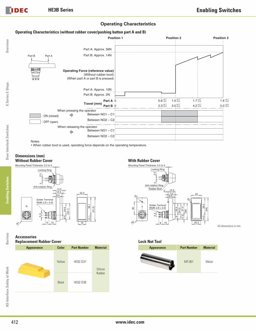
Operating Characteristics
Operating Characteristics (without rubber cover/pushing button part A and B)
Part A: Approx. 56N
Part B: Approx. 14N
Part A: Approx. 10N
Part B: Approx. 2N
Operating Force (reference value)(Without rubber boot)
(When part A or part B is pressed)
0Part ATravel (mm)
0.8 1.7 1.9+0.7–0.2
+0.7–0.2
+0.7–0.2
0Part B 2.3 4.2 5.0+0.7–0.3
1.0+0.7–0.2
3.0+0.7–0.3
+0.7–0.3
+0.4–0.3
When pressing the operator
When releasing the operator
Between NO2 – C2
Between NO1 – C1
Between NO2 – C2
Between NO1 – C1
Position 1 Position 2 Position 3
Part B Part A
Notes:• When rubber boot is used, operating force depends on the operating temperature.
: ON (closed)
: OFF (open)
Dimensions (mm)Without Rubber Cover With Rubber Cover
Locking Ring
Anti-rotation Ring
32.
5
Mounting Panel Thickness: 0.5 to 4
Solder TerminalWidth 2.8 × 0.5t
8 15
R1
55
13.1
38.1
22.2
16
8.5
14.5
8.5
24.6
12.3
(33.
1)
(51.
2)
Anti-rotation RingRubber Boot
32.
55
5
30
ø3
R2
13
(39)
11.5
27.5
(34.
5)9
25.5
15
2 15.5
9.5
8
25
39.5
14.5
(54)
R1
20.5
Solder TerminalWidth 2.8 × 0.5t
Locking Ring
Mounting Panel Thickness: 0.5 to 4
All dimensions in mm.
AccessoriesReplacement Rubber Cover Lock Nut Tool
Appearance Color Part Number Material Appearance Part Number Material
Yellow HE9Z-D3Y
Silicon Rubber
MT-001 Metal
Black HE9Z-D3B
HE5B SeriesEnabling Switches
413USA: 800-262-IDEC Canada: 888-317-IDEC
Overview
X S
eries E-Stops
Door Interlock S
witches
Enabling Sw
itchesB
arriersA
S-Interface S
afety at Work
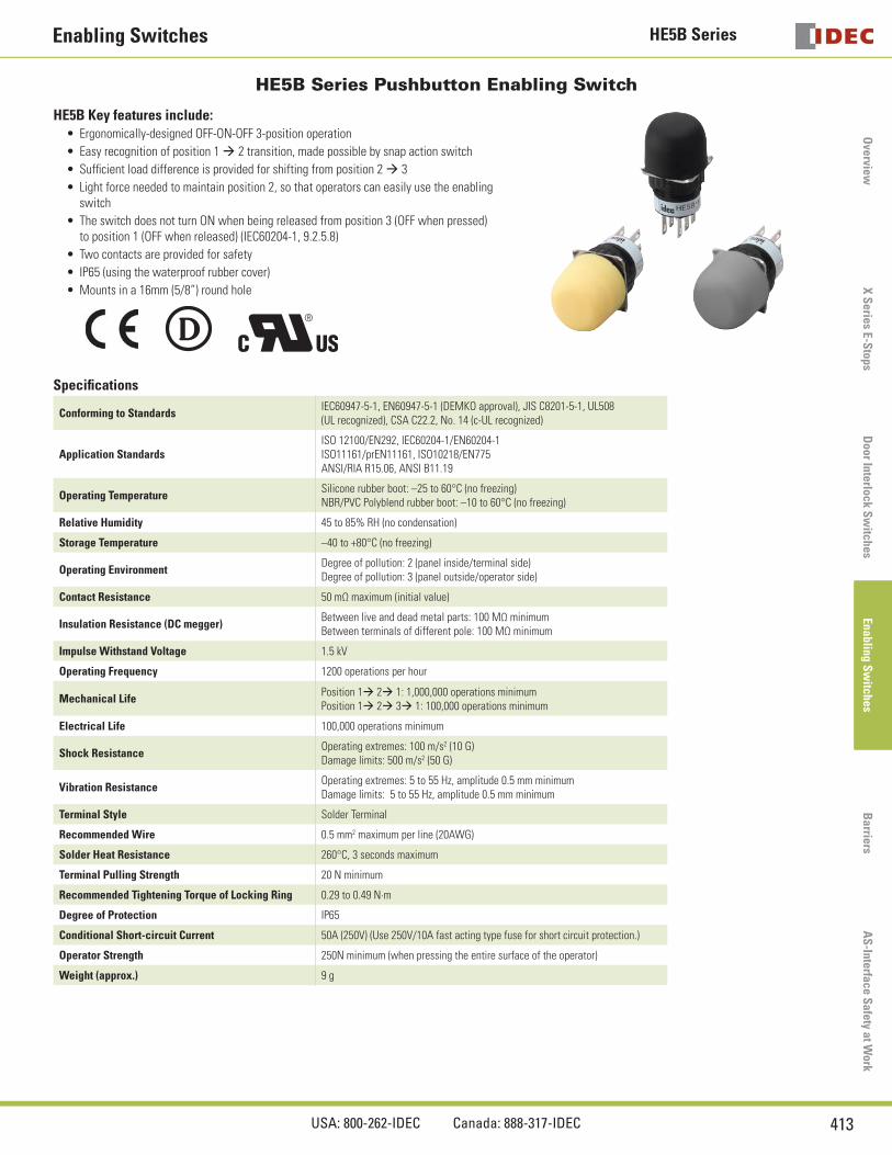
HE5B Series Pushbutton Enabling Switch
HE5B Key features include:Ergonomically-designed OFF-ON-OFF 3-position operation
Easy recognition of position 1 ‡ 2 transition, made possible by snap action switch
Suffi cient load difference is provided for shifting from position 2 ‡ 3
Light force needed to maintain position 2, so that operators can easily use the enabling switch
The switch does not turn ON when being released from position 3 (OFF when pressed) to position 1 (OFF when released) (IEC60204-1, 9.2.5.8)
Two contacts are provided for safety
IP65 (using the waterproof rubber cover)
Mounts in a 16mm (5/8”) round hole
•
•
•
•
•
•
•
•
Specifi cations
Conforming to StandardsIEC60947-5-1, EN60947-5-1 (DEMKO approval), JIS C8201-5-1, UL508 (UL recognized), CSA C22.2, No. 14 (c-UL recognized)
Application StandardsISO 12100/EN292, IEC60204-1/EN60204-1ISO11161/prEN11161, ISO10218/EN775ANSI/RIA R15.06, ANSI B11.19
Operating TemperatureSilicone rubber boot: –25 to 60°C (no freezing)NBR/PVC Polyblend rubber boot: –10 to 60°C (no freezing)
Relative Humidity 45 to 85% RH (no condensation)
Storage Temperature –40 to +80°C (no freezing)
Operating EnvironmentDegree of pollution: 2 (panel inside/terminal side)Degree of pollution: 3 (panel outside/operator side)
Contact Resistance 50 mΩ maximum (initial value)
Insulation Resistance (DC megger)Between live and dead metal parts: 100 MΩ minimumBetween terminals of different pole: 100 MΩ minimum
Impulse Withstand Voltage 1.5 kV
Operating Frequency 1200 operations per hour
Mechanical LifePosition 1‡ 2‡ 1: 1,000,000 operations minimumPosition 1‡ 2‡ 3‡ 1: 100,000 operations minimum
Electrical Life 100,000 operations minimum
Shock ResistanceOperating extremes: 100 m/s2 (10 G)Damage limits: 500 m/s2 (50 G)
Vibration ResistanceOperating extremes: 5 to 55 Hz, amplitude 0.5 mm minimumDamage limits: 5 to 55 Hz, amplitude 0.5 mm minimum
Terminal Style Solder Terminal
Recommended Wire 0.5 mm2 maximum per line (20AWG)
Solder Heat Resistance 260°C, 3 seconds maximum
Terminal Pulling Strength 20 N minimum
Recommended Tightening Torque of Locking Ring 0.29 to 0.49 N·m
Degree of Protection IP65
Conditional Short-circuit Current 50A (250V) (Use 250V/10A fast acting type fuse for short circuit protection.)
Operator Strength 250N minimum (when pressing the entire surface of the operator)
Weight (approx.) 9 g
HE5B Series Enabling Switches
414 www.idec.com
Ove
rvie
wX
Ser
ies
E-S
tops
Doo
r In
terl
ock
Sw
itch
es E
nabl
ing
Sw
itch
esB
arri
res
AS
-Int
erfa
ce S
afet
y at
Wor
k
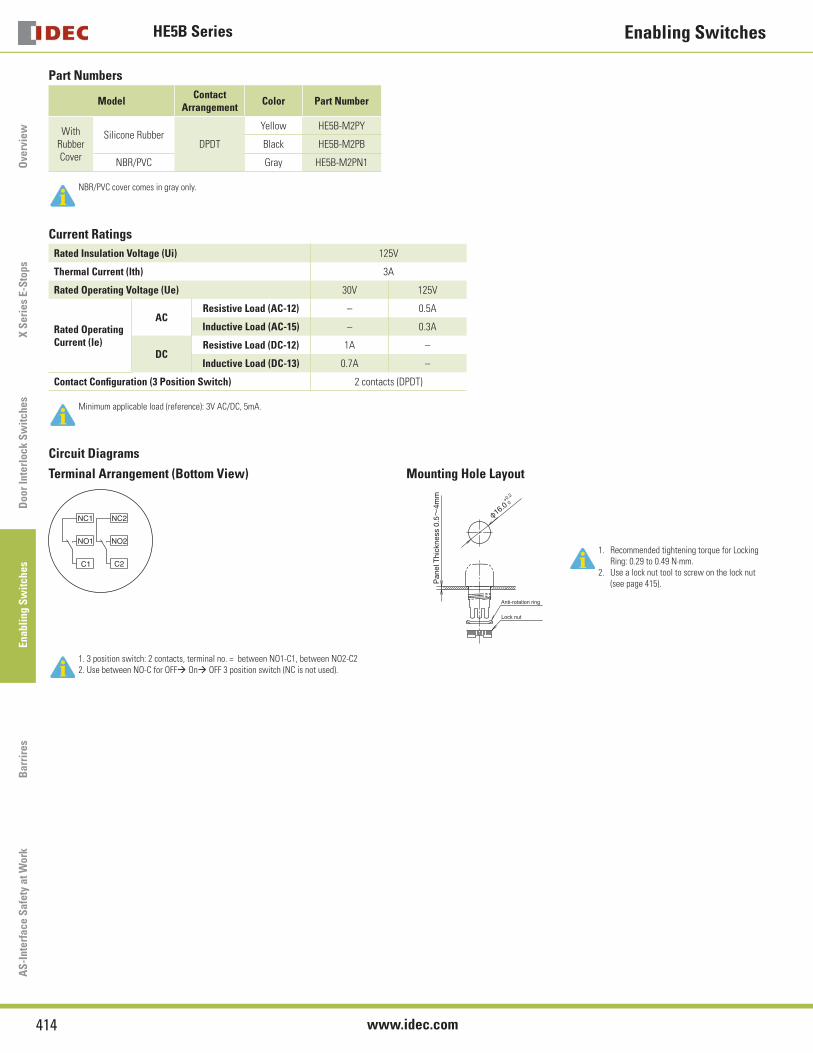
Part Numbers
ModelContact
ArrangementColor Part Number
With Rubber Cover
Silicone RubberDPDT
Yellow HE5B-M2PY
Black HE5B-M2PB
NBR/PVC Gray HE5B-M2PN1
NBR/PVC cover comes in gray only.
Current Ratings
Rated Insulation Voltage (Ui) 125V
Thermal Current (lth) 3A
Rated Operating Voltage (Ue) 30V 125V
Rated OperatingCurrent (le)
ACResistive Load (AC-12) – 0.5A
Inductive Load (AC-15) – 0.3A
DCResistive Load (DC-12) 1A –
Inductive Load (DC-13) 0.7A –
Contact Confi guration (3 Position Switch) 2 contacts (DPDT)
Minimum applicable load (reference): 3V AC/DC, 5mA.
Circuit Diagrams
Terminal Arrangement (Bottom View) Mounting Hole Layout
NC1 NC2
NO1
C1 C2
NO2
φ16.0+0.2
0
Pan
el T
hick
ness
0.5~
4mm
Anti-rotation ring
Lock nut
1. Recommended tightening torque for Locking Ring: 0.29 to 0.49 N·mm.
2. Use a lock nut tool to screw on the lock nut (see page 415).
1. 3 position switch: 2 contacts, terminal no. = between NO1-C1, between NO2-C22. Use between NO-C for OFF‡ On‡ OFF 3 position switch (NC is not used).
HE5B SeriesEnabling Switches
415USA: 800-262-IDEC Canada: 888-317-IDEC
Overview
X S
eries E-Stops
Door Interlock S
witches
Enabling Sw
itchesB
arriersA
S-Interface S
afety at Work
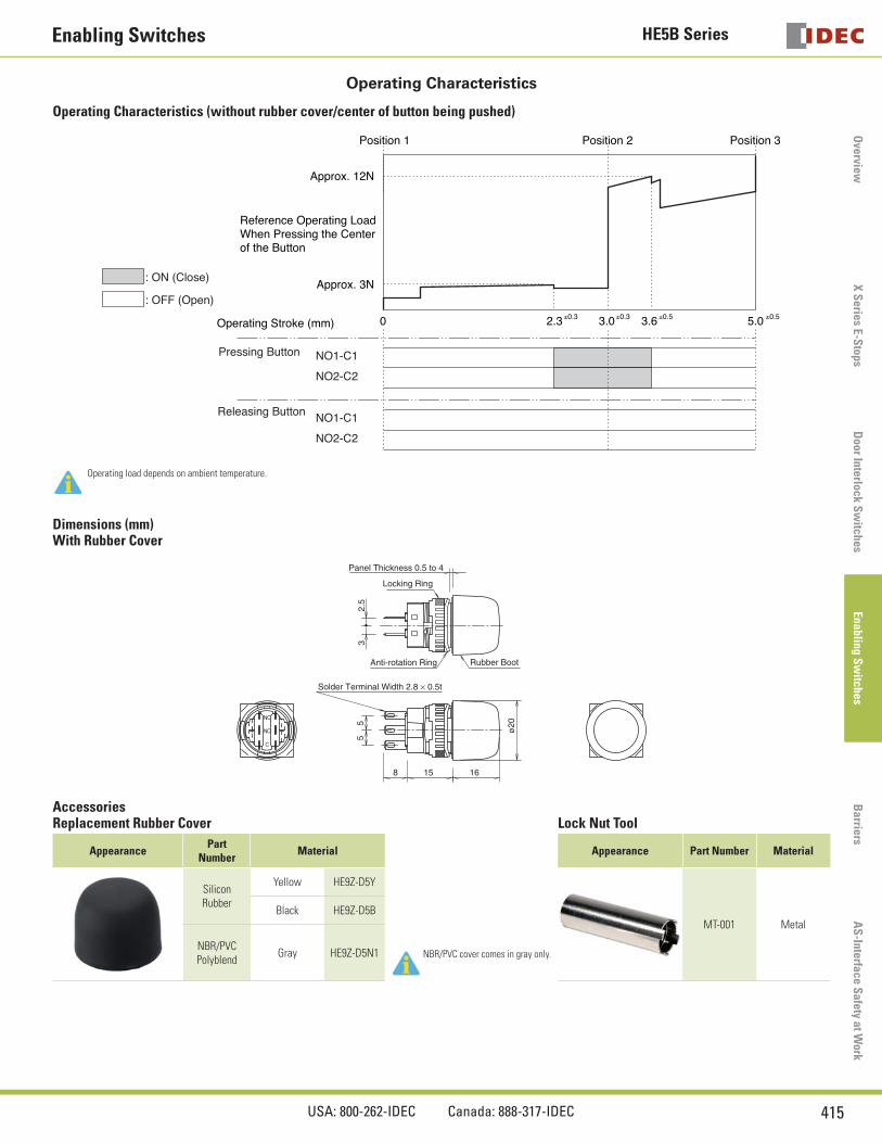
Operating Characteristics
Operating Characteristics (without rubber cover/center of button being pushed)
: ON (Close)
: OFF (Open)
Position 1 Position 2 Position 3
Approx. 12N
Approx. 3N
Reference Operating Load�When Pressing the Center�of the Button
Operating Stroke (mm)
NO1-C1Pressing Button
NO1-C1
NO2-C2
NO2-C2
Releasing Button
0 2.3 3.0 3.6 5.0±0.3 ±0.3 ±0.5 ±0.5
Operating load depends on ambient temperature.
Dimensions (mm)With Rubber Cover
Panel Thickness 0.5 to 4
2.5
3
Locking Ring
Anti-rotation Ring Rubber Boot
55
8 15
ø20
16
Solder Terminal Width 2.8 × 0.5t
AccessoriesReplacement Rubber Cover Lock Nut Tool
AppearancePart
NumberMaterial Appearance Part Number Material
Silicon Rubber
Yellow HE9Z-D5Y
NBR/PVC cover comes in gray only.
MT-001 MetalBlack HE9Z-D5B
NBR/PVC Polyblend
Gray HE9Z-D5N1
HE1G Series Enabling Switches
416 www.idec.com
Ove
rvie
wX
Ser
ies
E-S
tops
Doo
r In
terl
ock
Sw
itch
es E
nabl
ing
Sw
itch
esB
arri
res
AS
-Int
erfa
ce S
afet
y at
Wor
k
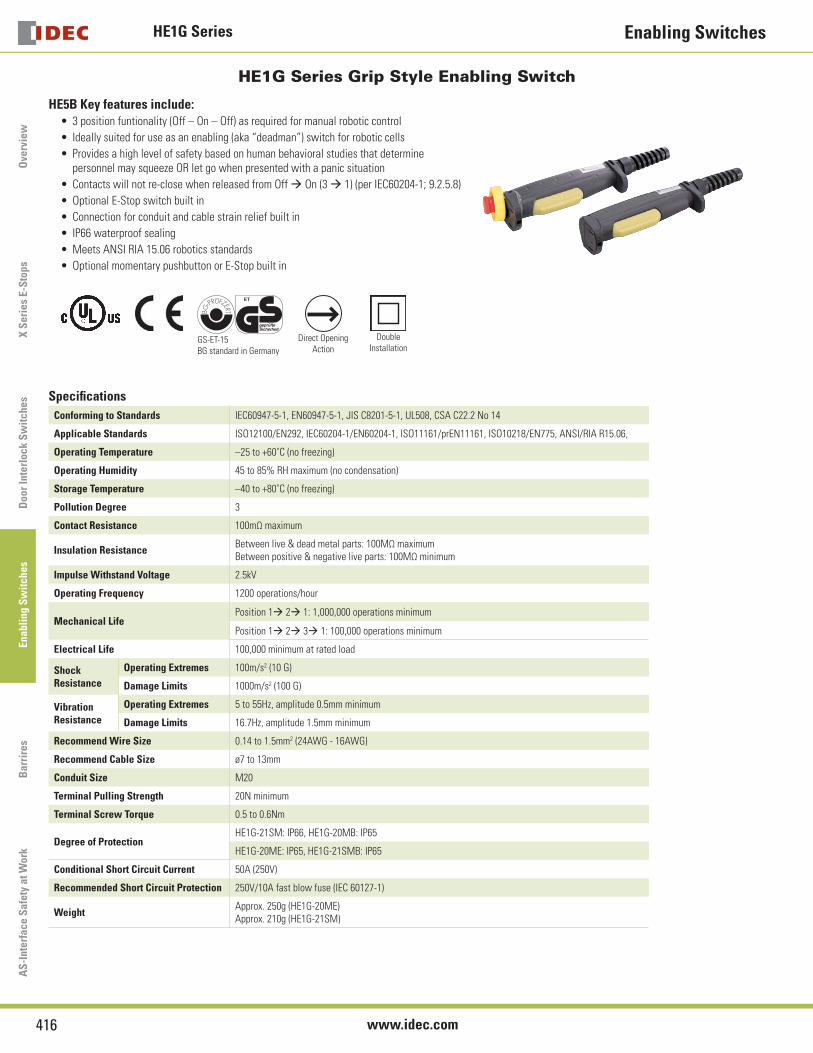
HE1G Series Grip Style Enabling Switch
HE5B Key features include:3 position funtionality (Off – On – Off) as required for manual robotic control
Ideally suited for use as an enabling (aka “deadman”) switch for robotic cells
Provides a high level of safety based on human behavioral studies that determine personnel may squeeze OR let go when presented with a panic situation
Contacts will not re-close when released from Off ‡ On (3 ‡ 1) (per IEC60204-1; 9.2.5.8)
Optional E-Stop switch built in
Connection for conduit and cable strain relief built in
IP66 waterproof sealing
Meets ANSI RIA 15.06 robotics standards
Optional momentary pushbutton or E-Stop built in
GS-ET-15 BG standard in Germany
Direct OpeningAction
DoubleInstallation
•
•
•
•
•
•
•
•
•
Specifi cations
Conforming to Standards IEC60947-5-1, EN60947-5-1, JIS C8201-5-1, UL508, CSA C22.2 No 14
Applicable Standards ISO12100/EN292, IEC60204-1/EN60204-1, ISO11161/prEN11161, ISO10218/EN775, ANSI/RIA R15.06,
Operating Temperature –25 to +60˚C (no freezing)
Operating Humidity 45 to 85% RH maximum (no condensation)
Storage Temperature –40 to +80˚C (no freezing)
Pollution Degree 3
Contact Resistance 100mΩ maximum
Insulation ResistanceBetween live & dead metal parts: 100MΩ maximumBetween positive & negative live parts: 100MΩ minimum
Impulse Withstand Voltage 2.5kV
Operating Frequency 1200 operations/hour
Mechanical LifePosition 1‡ 2‡ 1: 1,000,000 operations minimum
Position 1‡ 2‡ 3‡ 1: 100,000 operations minimum
Electrical Life 100,000 minimum at rated load
Shock Resistance
Operating Extremes 100m/s2 (10 G)
Damage Limits 1000m/s2 (100 G)
Vibration Resistance
Operating Extremes 5 to 55Hz, amplitude 0.5mm minimum
Damage Limits 16.7Hz, amplitude 1.5mm minimum
Recommend Wire Size 0.14 to 1.5mm2 (24AWG - 16AWG)
Recommend Cable Size ø7 to 13mm
Conduit Size M20
Terminal Pulling Strength 20N minimum
Terminal Screw Torque 0.5 to 0.6Nm
Degree of ProtectionHE1G-21SM: IP66, HE1G-20MB: IP65
HE1G-20ME: IP65, HE1G-21SMB: IP65
Conditional Short Circuit Current 50A (250V)
Recommended Short Circuit Protection 250V/10A fast blow fuse (IEC 60127-1)
Weight Approx. 250g (HE1G-20ME)Approx. 210g (HE1G-21SM)
HE1G SeriesEnabling Switches
417USA: 800-262-IDEC Canada: 888-317-IDEC
Overview
X S
eries E-Stops
Door Interlock S
witches
Enabling Sw
itchesB
arriersA
S-Interface S
afety at Work
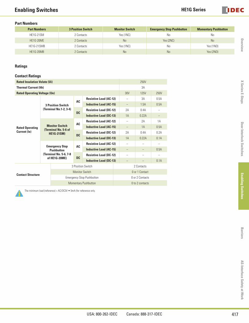
Part Numbers
Part Numbers 3 Position Switch Monitor Switch Emergency Stop Pushbutton Momentary Pushbutton
HE1G-21SM 2 Contacts Yes (1NC) No No
HE1G-20ME 2 Contacts No Yes (2NC) No
HE1G-21SMB 2 Contacts Yes (1NC) No Yes (1NO)
HE1G-20MB 2 Contacts No No Yes (2NO)
Ratings
Contact Ratings
Rated Insulation Volute (Ui) 250V
Thermal Current (lth) 3A
Rated Operating Voltage (Ue) 30V 125V 250V
Rated OperatingCurrent (le)
3 Position Switch(Terminal No.1-2, 3-4)
ACResistive Load (AC-12) – 3A 0.5A
Inductive Load (AC-15) – 1.5A 0.5A
DCResistive Load (DC-12) 2A 0.4A –
Inductive Load (DC-13) 1A 0.22A –
Monitor Switch(Terminal No. 5-6 of
HE1G-21SM)
ACResistive Load (AC-12) – 2A 1A
Inductive Load (AC-15) – 1A 0.5A
DCResistive Load (DC-12) 2A 0.4A 0.2A
Inductive Load (DC-13) 1A 0.22A 0.1A
Emergency Stop Pushbutton
(Terminal No. 5-6, 7-8 of HE1G-20ME)
ACResistive Load (AC-12) – – –
Inductive Load (AC-15) – – 0.5A
DCResistive Load (DC-12) – – –
Inductive Load (DC-13) – – 0.1A
Contact Structure
3 Position Switch 2 Contacts
Monitor Switch 0 or 1 Contact
Emergency Stop Pushbutton 0 or 2 Contacts
Momentary Pushbutton 0 to 2 contacts
The minimum load (reference) = AC/DC3V • 5mA (for reference only.
HE1G Series Enabling Switches
418 www.idec.com
Ove
rvie
wX
Ser
ies
E-S
tops
Doo
r In
terl
ock
Sw
itch
es E
nabl
ing
Sw
itch
esB
arri
res
AS
-Int
erfa
ce S
afet
y at
Wor
k
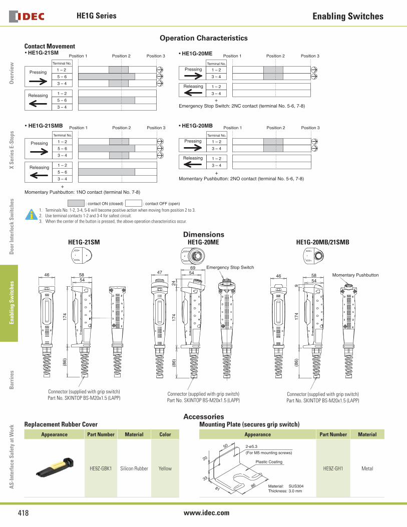
Operation CharacteristicsContact Movement
• HE1G-20MB
Terminal No.
1 – 2
3 – 4
Position 1 Position 2 Position 3
1 – 2
3 – 4
+Momentary Pushbutton: 2NO contact (terminal No. 5-6, 7-8)
Pressing
Releasing
• HE1G-20ME
Terminal No.
1 – 2
3 – 4
Position 1 Position 2 Position 3
1 – 2
3 – 4
+
Pressing
Releasing
Emergency Stop Switch: 2NC contact (terminal No. 5-6, 7-8)
: contact ON (closed) : contact OFF (open)
• HE1G-21SM
Terminal No.
1 – 2
5 – 6
3 – 4
1 – 2
5 – 6
3 – 4
Position 1 Position 2 Position 3
Pressing
Releasing
• HE1G-21SMB
+
1 – 2
5 – 6
3 – 4
1 – 2
5 – 6
3 – 4
Position 2 Position 3
Pressing
Releasing
Terminal No.
Position 1
Momentary Pushbutton: 1NO contact (terminal No. 7-8)
1. Terminals No. 1-2, 3-4, 5-6 will become positive action when moving from position 2 to 3.2. Use terminal contacts 1-2 and 3-4 for safest circuit.3. When the center of the button is pressed, the above operation characteristics occur.
DimensionsHE1G-21SM HE1G-20ME HE1G-20MB/21SMB
174
(86)
584654
Connector (supplied with grip switch)Part No. SKINTOP BS-M20x1.5 (LAPP)
Emergency Stop Switch
174
(86)
544769
24
Connector (supplied with grip switch)Part No. SKINTOP BS-M20x1.5 (LAPP)
917
4(8
6)
584654
Momentary Pushbutton
Connector (supplied with grip switch)Part No. SKINTOP BS-M20x1.5 (LAPP)
AccessoriesReplacement Rubber Cover Mounting Plate (secures grip switch)
Appearance Part Number Material Color Appearance Part Number Material
HE9Z-GBK1 Silicon Rubber Yellow
50
20
33
81Material: SUS304Thickness: 3.0 mm
2-ø5.3
(For M5 mounting screws)
86
Plastic Coating
HE9Z-GH1 Metal
General InformationEnabling Switches
419USA: 800-262-IDEC Canada: 888-317-IDEC
Overview
X S
eries E-Stops
Door Interlock S
witches
Enabling Sw
itchesB
arriersA
S-Interface S
afety at Work
General InformationSafety Precautions
In order to avoid electric shock or fi re, turn power off before installation, removal, wire connection, maintenance or inspection of switch.
Follow specifi cation when installing. Improper electrical load may damage switch, cause electric shock, or fi re.
•
•
Use proper wire diameter to meet voltage and current requirements. Using improper wires or incomplete soldering may cause fi re due to abnormal heat generation.
•
Installation Precautions HE2B
M3 nut is inside the rubber cover.
HE2B/HE3B
A change in internal air pressure may cause the rubber boot to expand and shrink on an enabling switch that has the rubber boot sealed. This may affect the performance of the switch. Periodically check to ensure that the enabling switch is operating correctly.
•
•
If the panel is not level when mounting an enabling switch, the waterproof feature cannot be guaranteed.
HE3B
The rubber boot has a tab to be used for orientation. When making a position-ing hole in a panel, do not make a hole in the rubber boot, or the waterproof feature cannot be guaranteed. When the positioning hole is not on the panel, remove the tab, but do not make a hole in the rubber boot.
When tightening the locking ring, secure the fl ange to prevent the enabling switch from rotating. In applications where the enabling switch is to be rotated, mount the switch in a recess on the panel as shown.
Locking RingAnti-rotation Ring
PositioningProjection
Mounting Panel
•
•
•
Wiring Precautions HE1B/HE2B/HE3B
Applicable wire size is 0.5mm2 (20AWG) (maximum) / 1 line.
When soldering the terminal, solder at a temperature of 260°C within 3 seconds. Use non-corrosive liquid rosin as soldering fl ux.
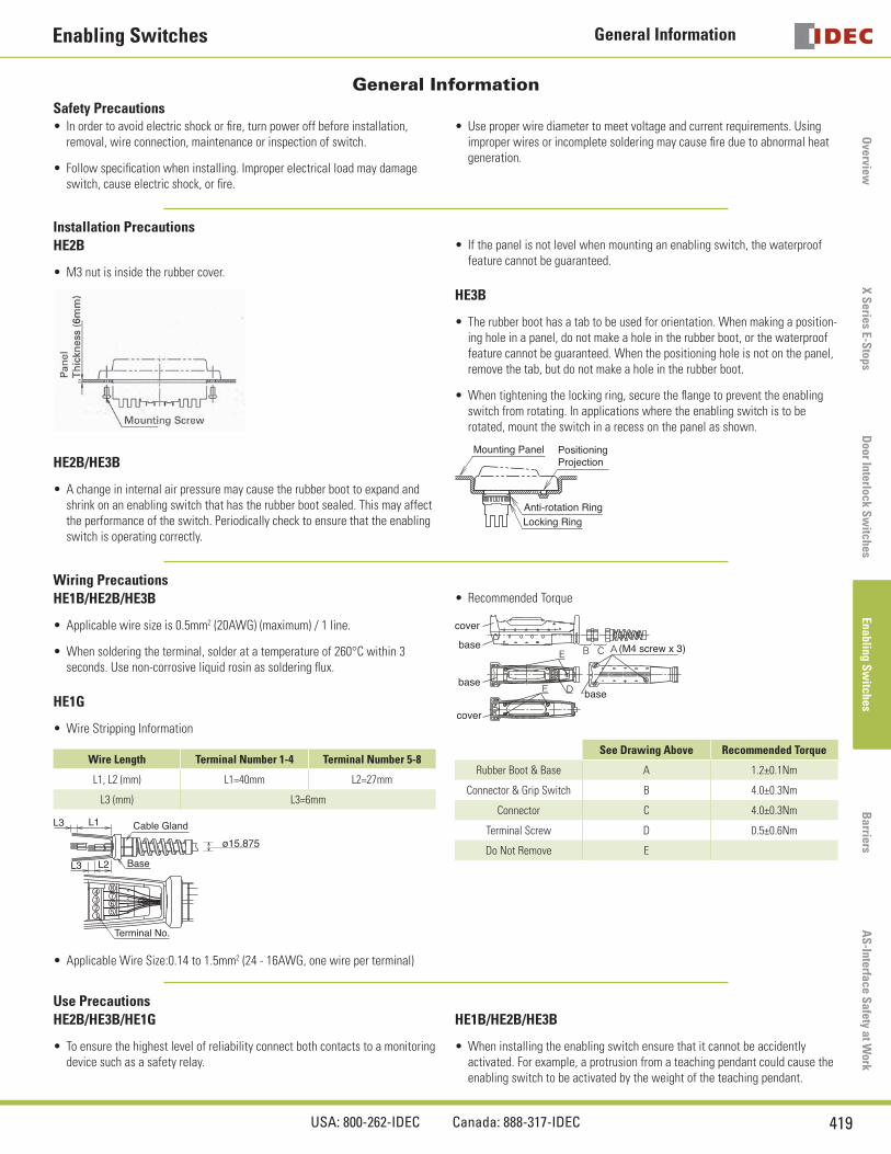
HE1G
Wire Stripping Information
Wire Length Terminal Number 1-4 Terminal Number 5-8
L1, L2 (mm) L1=40mm L2=27mm
L3 (mm) L3=6mm
Cable Gland
Base
Terminal No.
L3 L1
L3 L2
ø15.875
Applicable Wire Size:0.14 to 1.5mm2 (24 - 16AWG, one wire per terminal)
•
•
•
•
Recommended Torque
cover
base
base
cover
base
(M4 screw x 3)
See Drawing Above Recommended Torque
Rubber Boot & Base A 1.2±0.1Nm
Connector & Grip Switch B 4.0±0.3Nm
Connector C 4.0±0.3Nm
Terminal Screw D 0.5±0.6Nm
Do Not Remove E
•
Use PrecautionsHE2B/HE3B/HE1G
To ensure the highest level of reliability connect both contacts to a monitoring device such as a safety relay.
•
HE1B/HE2B/HE3B
When installing the enabling switch ensure that it cannot be accidently activated. For example, a protrusion from a teaching pendant could cause the enabling switch to be activated by the weight of the teaching pendant.
•
Enabling Switches
420 www.idec.com
Ove
rvie
wX
Ser
ies
E-S
tops
Doo
r In
terl
ock
Sw
itch
es E
nabl
ing
Sw
itch
esB
arri
res
AS
-Int
erfa
ce S
afet
y at
Wor
k