ElectronicCircuitsICh-1 CH1 Basic circuits 基礎回路
27
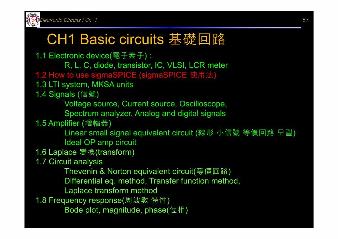
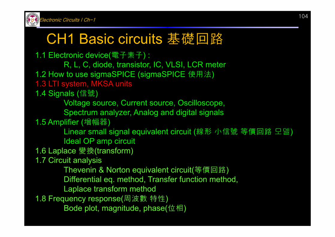
Electronic Circuits I Ch-1 87 CH1 Basic circuits 基礎回路 1.1 Electronic device(電子素子) : R, L, C, diode, transistor, IC, VLSI, LCR meter 1.2 How to use sigmaSPICE (sigmaSPICE 使用法) 1.3 LTI system, MKSA units 1.4 Signals (信號) Voltage source, Current source, Oscilloscope, Spectrum analyzer, Analog and digital signals 1.5 Amplifier (增幅器) Linear small signal equivalent circuit (線形 小信號 等價回路 모델) Ideal OP amp circuit 1.6 Laplace 變換(transform) 1.7 Circuit analysis Thevenin & Norton equivalent circuit(等價回路) Differential eq. method, Transfer function method, Laplace transform method 1.8 Frequency response(周波數 特性) Bode plot, magnitude, phase(位相)
Transcript of ElectronicCircuitsICh-1 CH1 Basic circuits 基礎回路
Electronic Circuits I Ch-1 87
CH1 Basic circuits 基礎回路1.1 Electronic device(電子素子) :
R, L, C, diode, transistor, IC, VLSI, LCR meter1.2 How to use sigmaSPICE (sigmaSPICE 使用法)1.3 LTI system, MKSA units1.4 Signals (信號)
Voltage source, Current source, Oscilloscope, Spectrum analyzer, Analog and digital signals
1.5 Amplifier (增幅器)Linear small signal equivalent circuit (線形 小信號 等價回路 모델)Ideal OP amp circuit
1.6 Laplace 變換(transform)1.7 Circuit analysis
Thevenin & Norton equivalent circuit(等價回路)Differential eq. method, Transfer function method, Laplace transform method
1.8 Frequency response(周波數 特性)Bode plot, magnitude, phase(位相)
Electronic Circuits I Ch-188
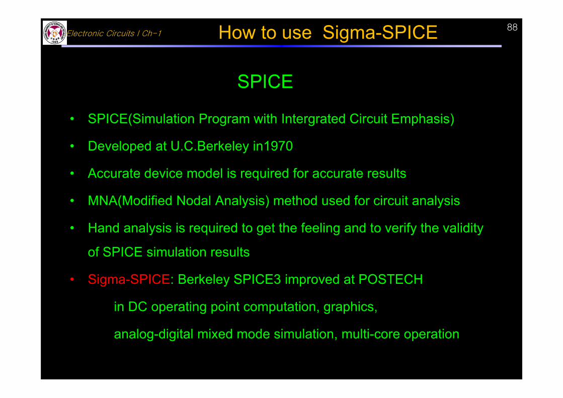
• SPICE(Simulation Program with Intergrated Circuit Emphasis)
• Developed at U.C.Berkeley in1970
• Accurate device model is required for accurate results
• MNA(Modified Nodal Analysis) method used for circuit analysis
• Hand analysis is required to get the feeling and to verify the validity
of SPICE simulation results
• Sigma-SPICE: Berkeley SPICE3 improved at POSTECH
in DC operating point computation, graphics,
analog-digital mixed mode simulation, multi-core operation
SPICE
How to use Sigma-SPICE
Electronic Circuits I Ch-1
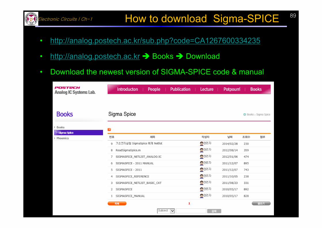
• http://analog.postech.ac.kr/sub.php?code=CA1267600334235
• http://analog.postech.ac.kr Books Download
• Download the newest version of SIGMA-SPICE code & manual
How to download Sigma-SPICE 89
Electronic Circuits I Ch-190
• MNA(modified nodal analysis) method• Nodal analysis method
- Apply KCL to calculate the node voltage- Cannot solve the circuit equation including voltage source, inductor, controlled voltage source
• MNA(Modifide Nodal Analysis) method- Apply KCL to each node- Apply KVL to voltage source, inductor, controlled voltage source
Circuit equation: a combination of KCL & KVLVariables of circuit equations:
all node voltages, the current through voltage source & inductor
SPICE circuit analysis method
How to use Sigma-SPICE
Electronic Circuits I Ch-191
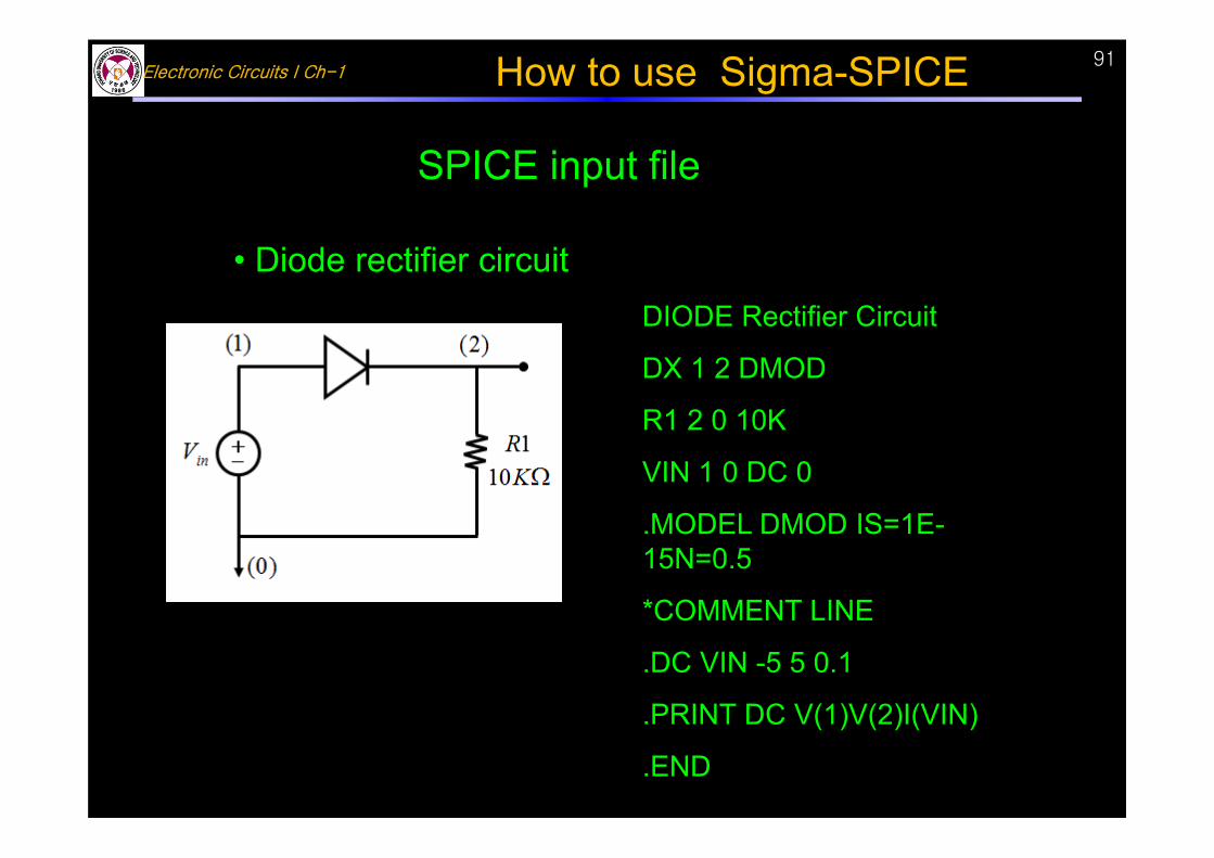
SPICE input file
• Diode rectifier circuitDIODE Rectifier Circuit
DX 1 2 DMOD
R1 2 0 10K
VIN 1 0 DC 0
.MODEL DMOD IS=1E-15N=0.5
*COMMENT LINE
.DC VIN -5 5 0.1
.PRINT DC V(1)V(2)I(VIN)
.END
How to use Sigma-SPICE
Electronic Circuits I Ch-1
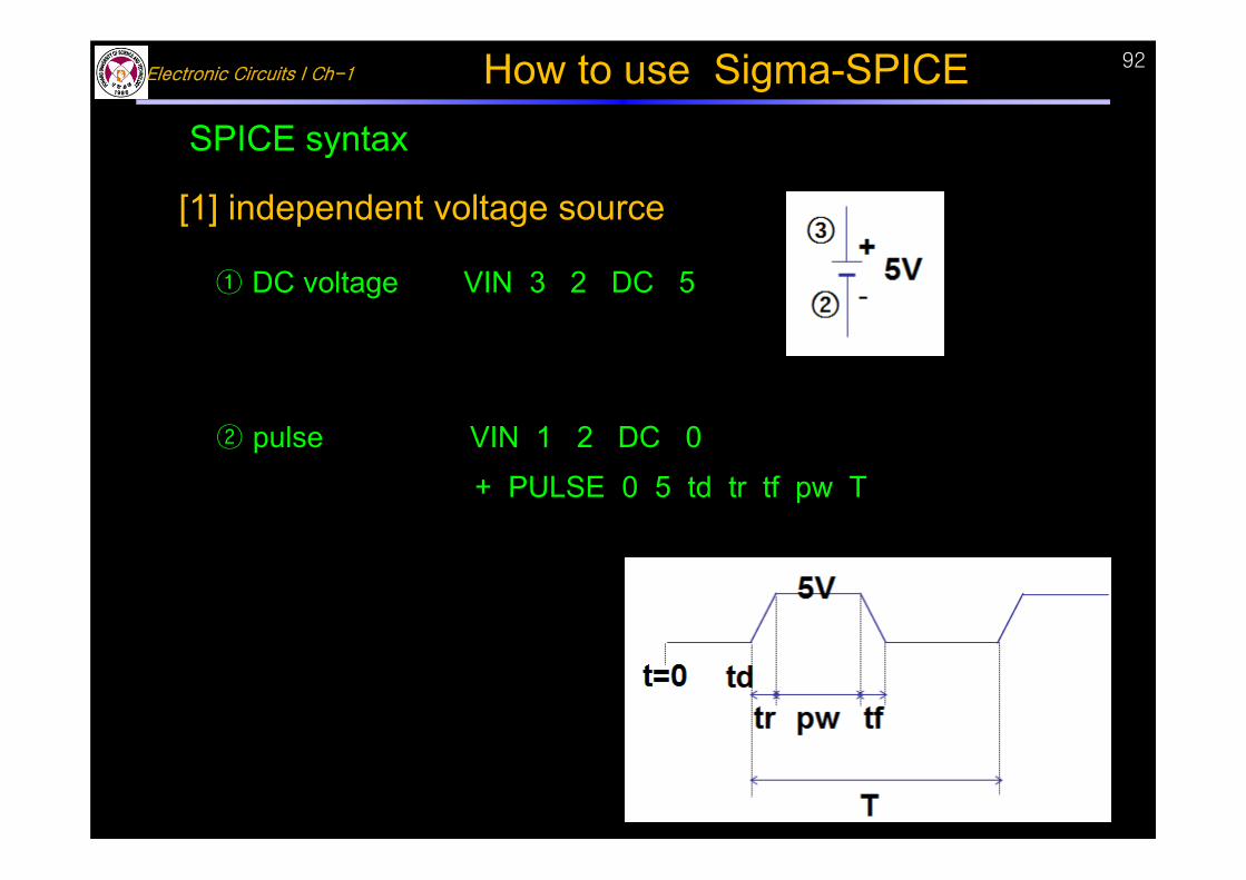
SPICE syntax
② pulse VIN 1 2 DC 0
+ PULSE 0 5 td tr tf pw T
[1] independent voltage source
① DC voltage VIN 3 2 DC 5
How to use Sigma-SPICE 92
Electronic Circuits I Ch-193
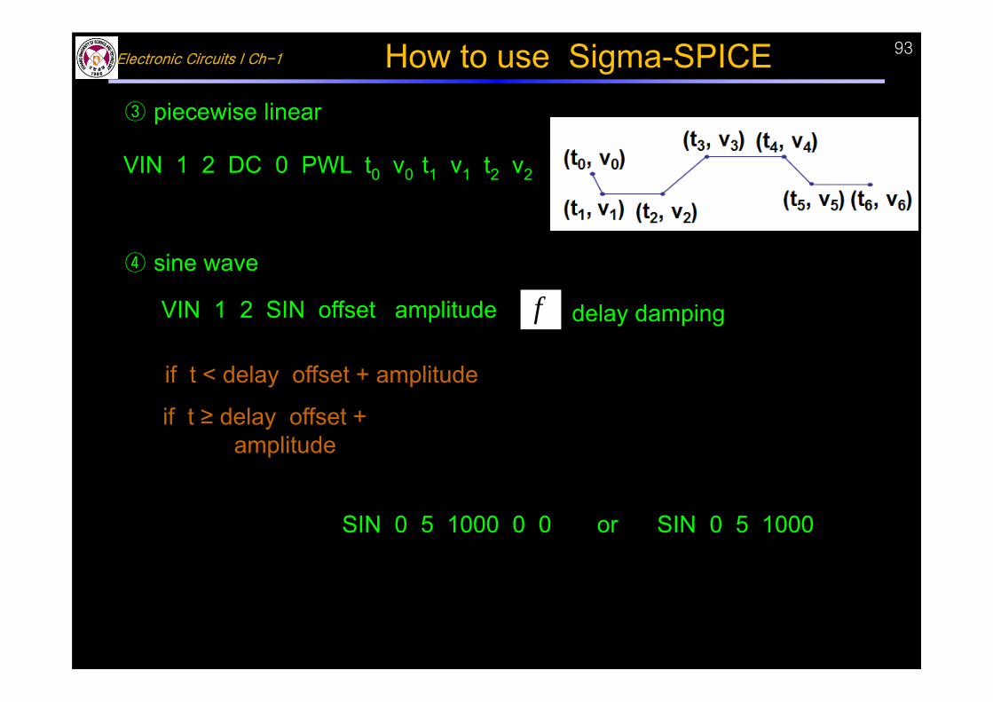
VIN 1 2 DC 0 PWL t0 v0 t1 v1 t2 v2
f delay damping
if t < delay offset + amplitude
2
360sin
if t ≥ delay offset + amplitude )( delaytdampinge
360
)(2sin delaytf
)10002(sin5 t SIN 0 5 1000 0 0 or SIN 0 5 1000
VIN 1 2 SIN offset amplitude
③ piecewise linear
④ sine wave
How to use Sigma-SPICE
Electronic Circuits I Ch-194
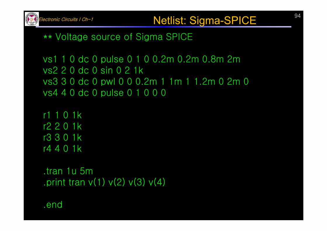
** Voltage source of Sigma SPICE
vs1 1 0 dc 0 pulse 0 1 0 0.2m 0.2m 0.8m 2mvs2 2 0 dc 0 sin 0 2 1kvs3 3 0 dc 0 pwl 0 0 0.2m 1 1m 1 1.2m 0 2m 0 vs4 4 0 dc 0 pulse 0 1 0 0 0
r1 1 0 1kr2 2 0 1kr3 3 0 1kr4 4 0 1k
.tran 1u 5m
.print tran v(1) v(2) v(3) v(4)
.end
Netlist: Sigma-SPICE
Electronic Circuits I Ch-195
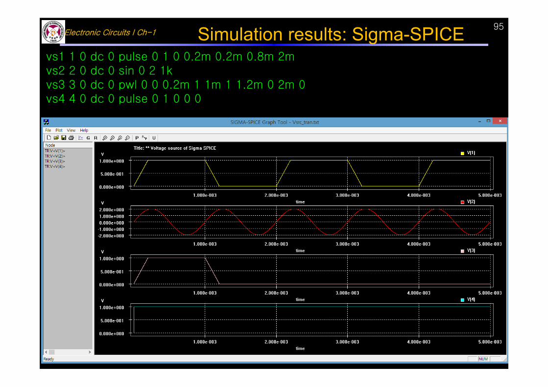
vs1 1 0 dc 0 pulse 0 1 0 0.2m 0.2m 0.8m 2mvs2 2 0 dc 0 sin 0 2 1kvs3 3 0 dc 0 pwl 0 0 0.2m 1 1m 1 1.2m 0 2m 0 vs4 4 0 dc 0 pulse 0 1 0 0 0
Simulation results: Sigma-SPICE
Electronic Circuits I Ch-196
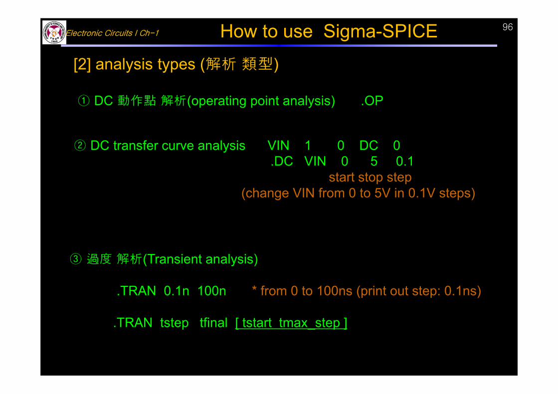
③ 過度 解析(Transient analysis)
.TRAN 0.1n 100n * from 0 to 100ns (print out step: 0.1ns)
.TRAN tstep tfinal [ tstart tmax_step ]
[2] analysis types (解析 類型)
① DC 動作點 解析(operating point analysis) .OP
② DC transfer curve analysis VIN 1 0 DC 0.DC VIN 0 5 0.1
start stop step(change VIN from 0 to 5V in 0.1V steps)
How to use Sigma-SPICE
Electronic Circuits I Ch-197
97
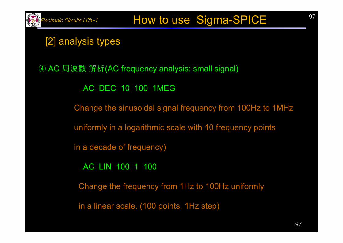
④ AC 周波數 解析(AC frequency analysis: small signal)
.AC DEC 10 100 1MEG
Change the sinusoidal signal frequency from 100Hz to 1MHz
uniformly in a logarithmic scale with 10 frequency points
in a decade of frequency)
.AC LIN 100 1 100
Change the frequency from 1Hz to 100Hz uniformly
in a linear scale. (100 points, 1Hz step)
[2] analysis types
How to use Sigma-SPICE
Electronic Circuits I Ch-198
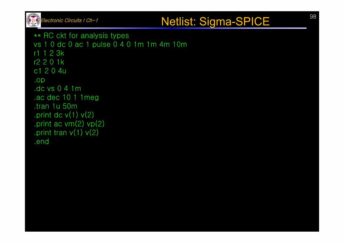
** RC ckt for analysis typesvs 1 0 dc 0 ac 1 pulse 0 4 0 1m 1m 4m 10mr1 1 2 3kr2 2 0 1kc1 2 0 4u.op.dc vs 0 4 1m.ac dec 10 1 1meg.tran 1u 50m.print dc v(1) v(2).print ac vm(2) vp(2).print tran v(1) v(2).end
Netlist: Sigma-SPICE
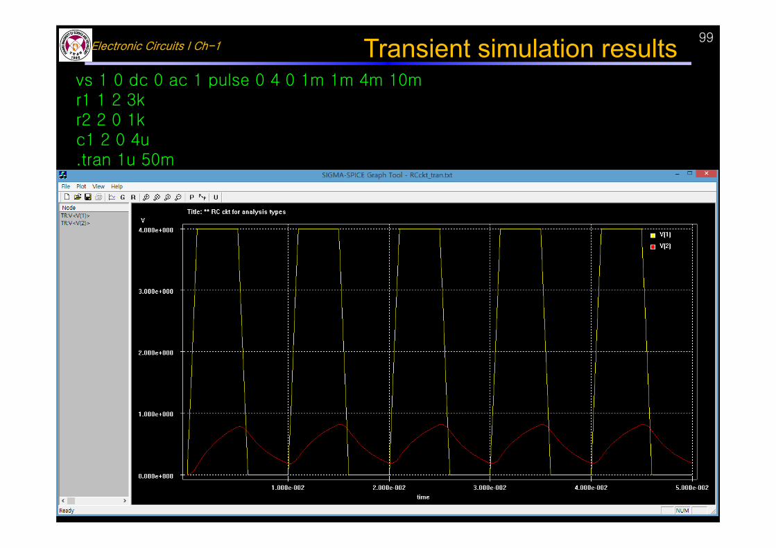
Electronic Circuits I Ch-199Transient simulation results
vs 1 0 dc 0 ac 1 pulse 0 4 0 1m 1m 4m 10mr1 1 2 3kr2 2 0 1kc1 2 0 4u.tran 1u 50m
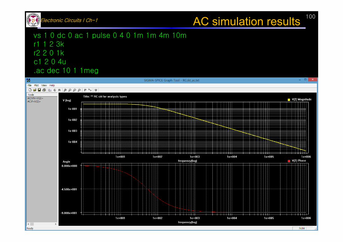
Electronic Circuits I Ch-1100AC simulation results
vs 1 0 dc 0 ac 1 pulse 0 4 0 1m 1m 4m 10mr1 1 2 3kr2 2 0 1kc1 2 0 4u.ac dec 10 1 1meg
Electronic Circuits I Ch-1101
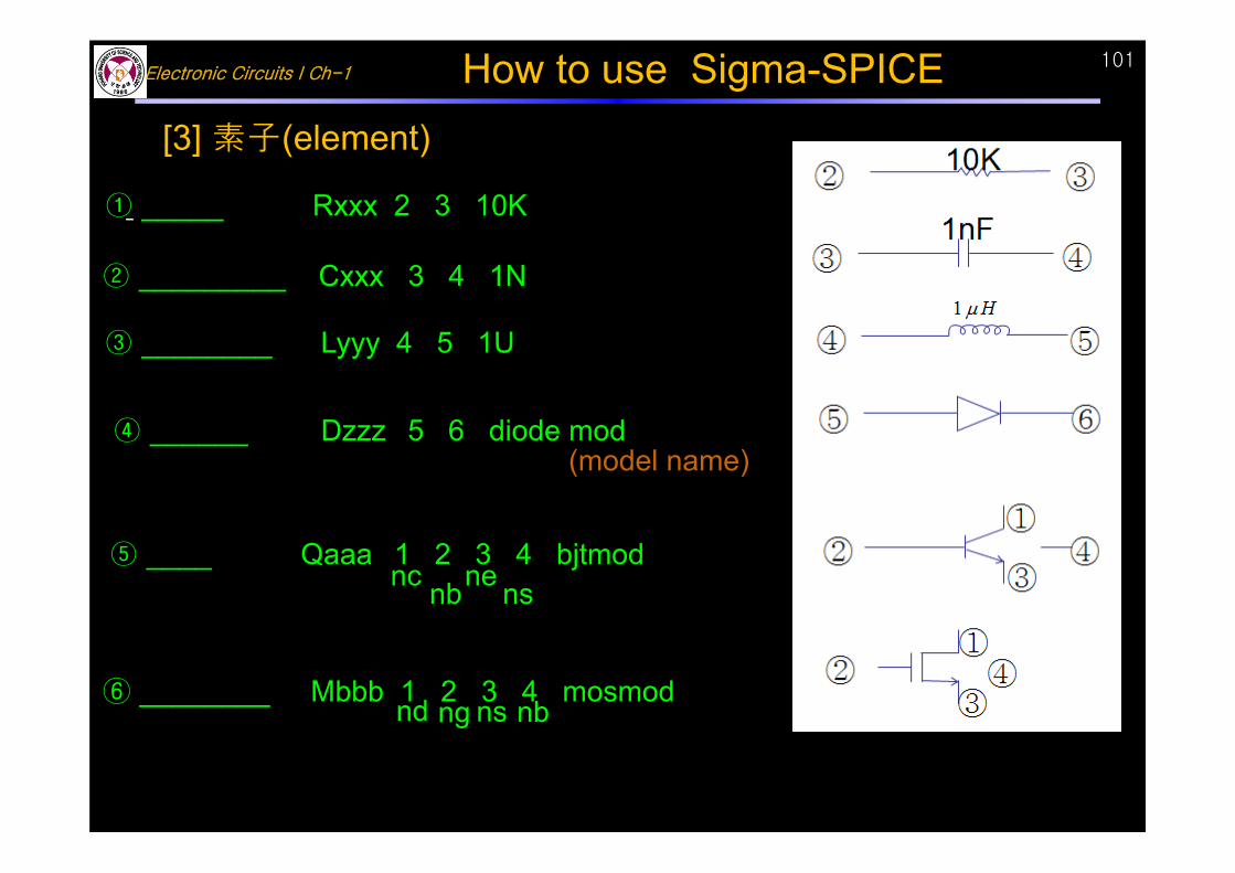
[3] 素子(element)
③ ________ Lyyy 4 5 1U
(model name)④ ______ Dzzz 5 6 diode mod
nc nb nsne⑤ ____ Qaaa 1 2 3 4 bjtmod
nd ng ns nb⑥ ________ Mbbb 1 2 3 4 mosmod
① _____ Rxxx 2 3 10K
② _________ Cxxx 3 4 1N
How to use Sigma-SPICE
Electronic Circuits I Ch-1102
102
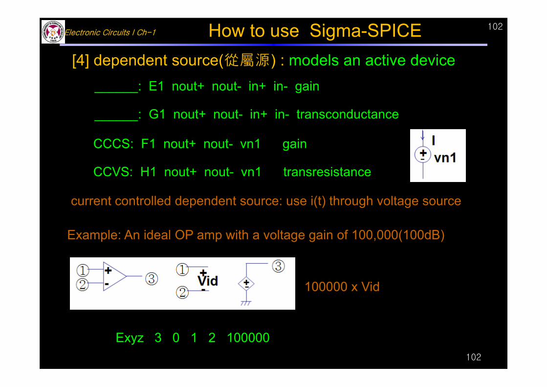
current controlled dependent source: use i(t) through voltage source
Example: An ideal OP amp with a voltage gain of 100,000(100dB)
[4] dependent source(從屬源) : models an active device______: E1 nout+ nout- in+ in- gain
______: G1 nout+ nout- in+ in- transconductance
CCCS: F1 nout+ nout- vn1 gain
CCVS: H1 nout+ nout- vn1 transresistance
Exyz 3 0 1 2 100000
How to use Sigma-SPICE
100000 x Vid
Electronic Circuits I Ch-1103
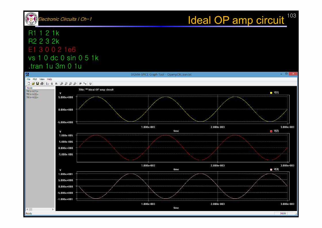
R1 1 2 1kR2 2 3 2kE1 3 0 0 2 1e6vs 1 0 dc 0 sin 0 5 1k.tran 1u 3m 0 1u
Ideal OP amp circuit
Electronic Circuits I Ch-1104
CH1 Basic circuits 基礎回路1.1 Electronic device(電子素子) :
R, L, C, diode, transistor, IC, VLSI, LCR meter1.2 How to use sigmaSPICE (sigmaSPICE 使用法)1.3 LTI system, MKSA units1.4 Signals (信號)
Voltage source, Current source, Oscilloscope, Spectrum analyzer, Analog and digital signals
1.5 Amplifier (增幅器)Linear small signal equivalent circuit (線形 小信號 等價回路 모델)Ideal OP amp circuit
1.6 Laplace 變換(transform)1.7 Circuit analysis
Thevenin & Norton equivalent circuit(等價回路)Differential eq. method, Transfer function method, Laplace transform method
1.8 Frequency response(周波數 特性)Bode plot, magnitude, phase(位相)
Electronic Circuits I Ch-1
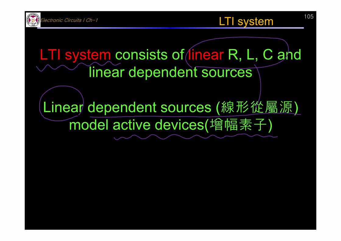
LTI system consists of linear R, L, C and linear dependent sources
Linear dependent sources (線形從屬源)model active devices(增幅素子)
LTI system 105
Electronic Circuits I Ch-1
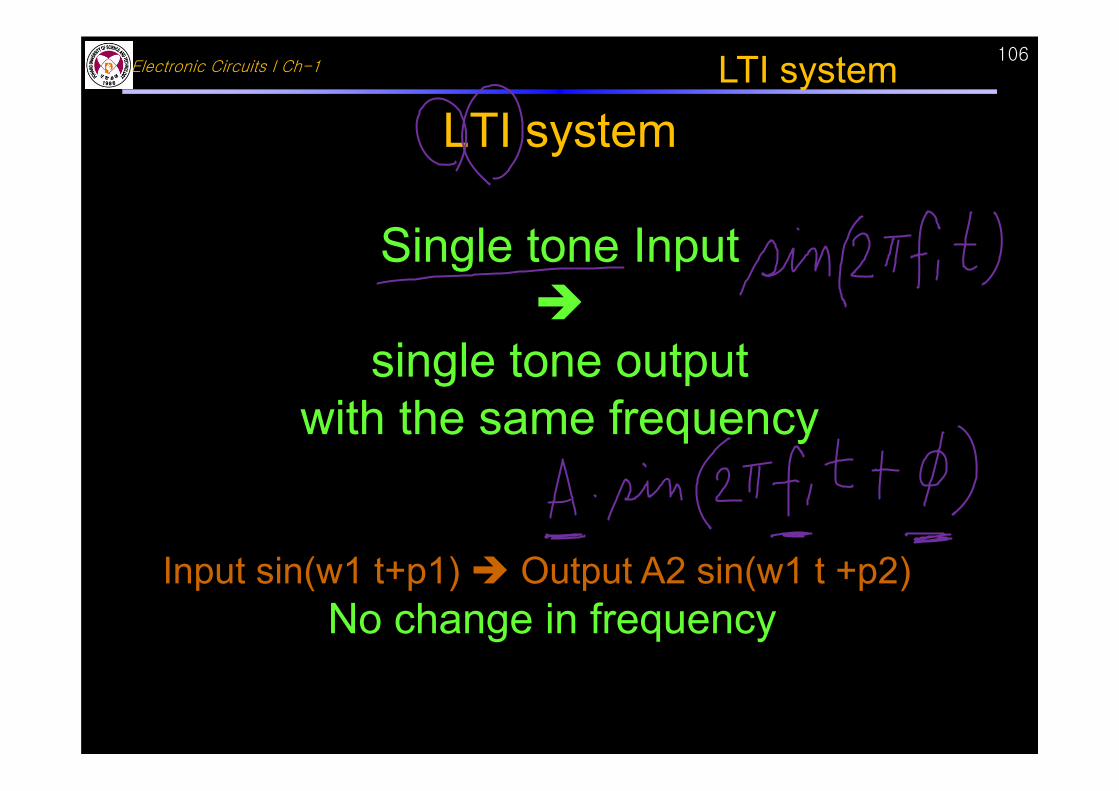
LTI system
Single tone Input
single tone output with the same frequency
Input sin(w1 t+p1) Output A2 sin(w1 t +p2) No change in frequency
LTI system 106
Electronic Circuits I Ch-1107
Dependent source 從屬電源종속전원independent source 獨立電源독립전원
Dependent source models active devices (transistors: amplifier(增幅器)) VCVS, VCCS, CCVS, CCCS
LTI system
Electronic Circuits I Ch-1108
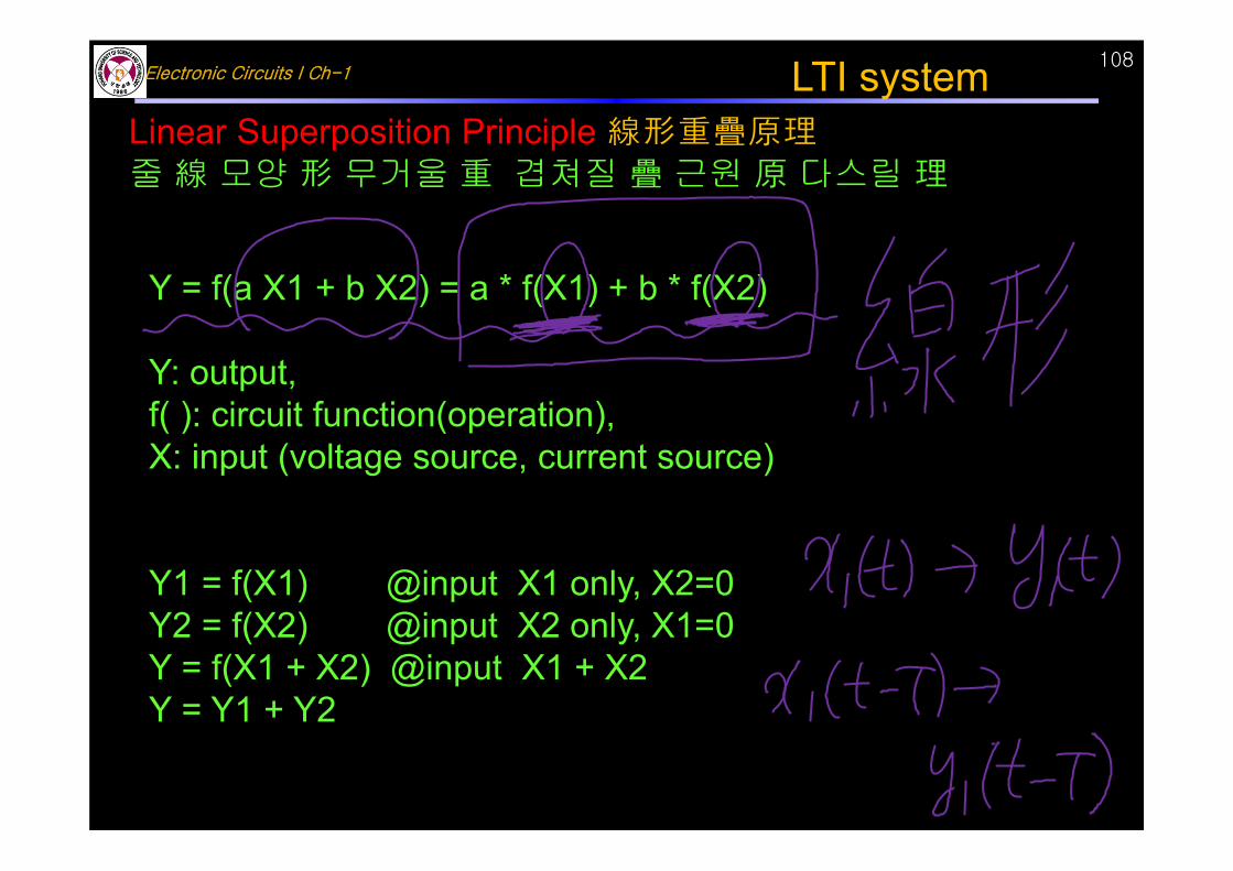
Linear Superposition Principle 線形重疊原理줄 線 모양 形 무거울 重 겹쳐질 疊 근원 原 다스릴 理
Y = f(a X1 + b X2) = a * f(X1) + b * f(X2)
Y: output, f( ): circuit function(operation), X: input (voltage source, current source)
Y1 = f(X1) @input X1 only, X2=0Y2 = f(X2) @input X2 only, X1=0Y = f(X1 + X2) @input X1 + X2Y = Y1 + Y2
LTI system
Electronic Circuits I Ch-1109
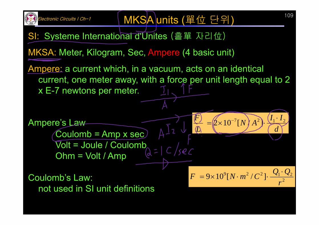
SI: Systeme International d'Unites (홑單 자리位)
MKSA: Meter, Kilogram, Sec, Ampere (4 basic unit)
Ampere: a current which, in a vacuum, acts on an identical current, one meter away, with a force per unit length equal to 2 x E-7 newtons per meter.
Ampere’s LawCoulomb = Amp x secVolt = Joule / CoulombOhm = Volt / Amp
Coulomb’s Law: not used in SI unit definitions
MKSA units (單位 단위)
dIIAN
LF 2127 ]/[102
221229 ]/[109
rQQCmNF
Electronic Circuits I Ch-1110
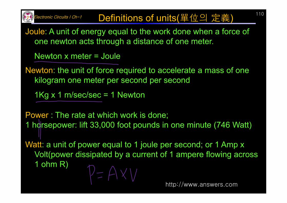
Joule: A unit of energy equal to the work done when a force of one newton acts through a distance of one meter.
Newton x meter = Joule
Newton: the unit of force required to accelerate a mass of one kilogram one meter per second per second
1Kg x 1 m/sec/sec = 1 Newton
Power : The rate at which work is done; 1 horsepower: lift 33,000 foot pounds in one minute (746 Watt)
Watt: a unit of power equal to 1 joule per second; or 1 Amp x Volt(power dissipated by a current of 1 ampere flowing across 1 ohm R)
http://www.answers.com
Definitions of units(單位의 定義)
Electronic Circuits I Ch-1111
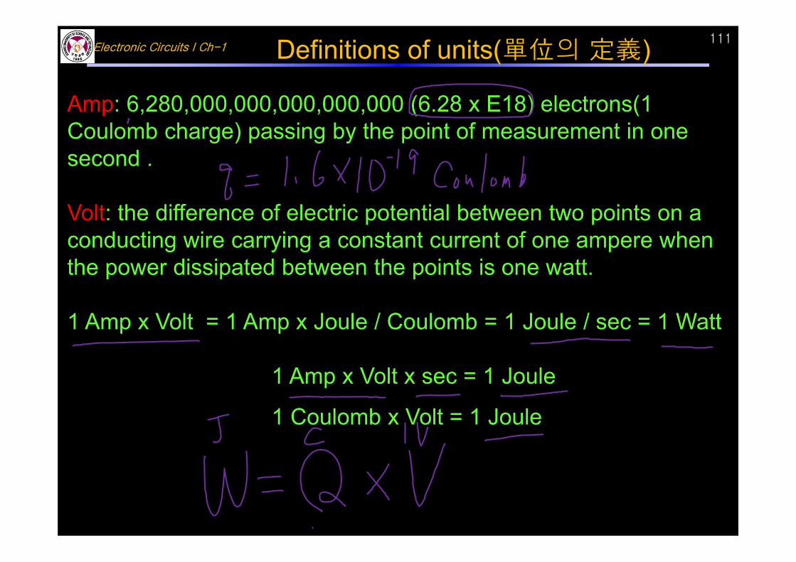
Amp: 6,280,000,000,000,000,000 (6.28 x E18) electrons(1 Coulomb charge) passing by the point of measurement in one second .
Volt: the difference of electric potential between two points on a conducting wire carrying a constant current of one ampere when the power dissipated between the points is one watt.
1 Amp x Volt = 1 Amp x Joule / Coulomb = 1 Joule / sec = 1 Watt
1 Amp x Volt x sec = 1 Joule
1 Coulomb x Volt = 1 Joule
Definitions of units(單位의 定義)
Electronic Circuits I Ch-1112
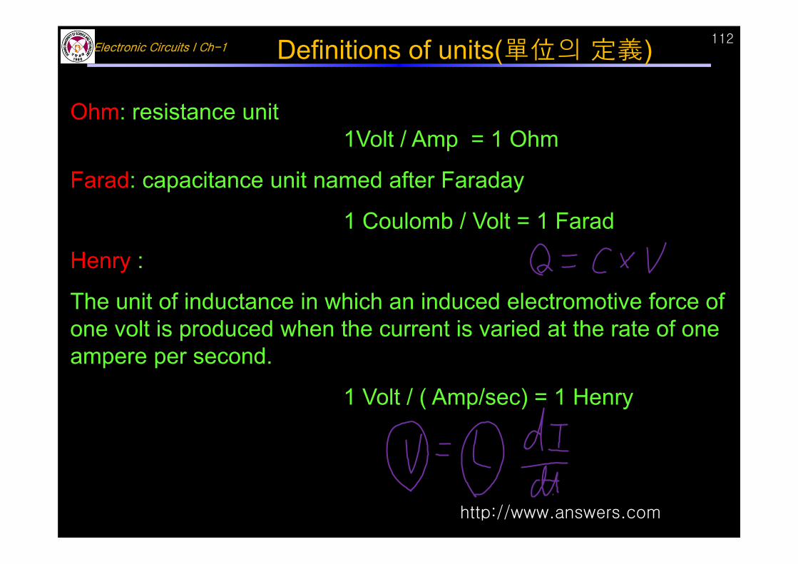
Ohm: resistance unit1Volt / Amp = 1 Ohm
Farad: capacitance unit named after Faraday
1 Coulomb / Volt = 1 Farad
Henry :
The unit of inductance in which an induced electromotive force of one volt is produced when the current is varied at the rate of one ampere per second.
1 Volt / ( Amp/sec) = 1 Henry
http://www.answers.com
Definitions of units(單位의 定義)
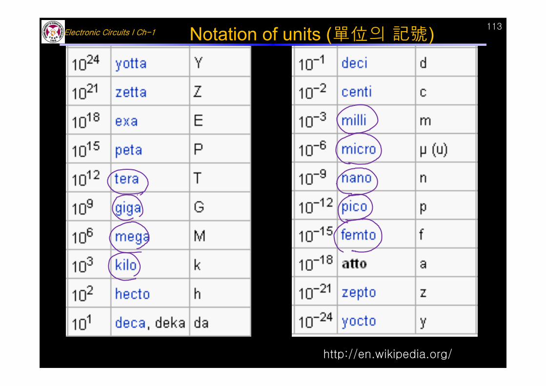
Electronic Circuits I Ch-1113Notation of units (單位의 記號)
http://en.wikipedia.org/


![ch1 [MARPHOLOGY]](https://static.fdocument.pub/doc/165x107/577c828e1a28abe054b14555/ch1-marphology.jpg)