Electrical Distribution System Engineering Dependable ... · Buss Fuse Selection Chart ......
32
Engineering Dependable Protection - Part III "Component Protection for Electrical Systems" Table of Contents Page Basic Considerations of Component Protection …………………………………………………………3 Buss Fuse Selection Chart …………………………………………………………..……………………32 - The National Electrical Code and Component Protection …………………………………………3 - Calculating Short-Circuit Currents ……………………………………………………………………3 Current-Limitation ……………………………………………………………………………………………4 - Analysis of Current-Limiting Fuse Let-Thru Charts …………………………………………………5 Let-Thru Data Pertinent to Equipment Withstand …………………………………………………………6 - How to Use the Let-Thru Charts ………………………………………………………………………6 A Practical Approach - Protecting System Components ………………………………………………7 - A. Wire and Cable Protection …………………………………………………………………………7 - B. Bus Short-Circuit Rating and Bracing Requirements …………………………………………15 - C.Low Voltage Motor Controllers ……………………………………………………………………18 - D. Molded Case Circuit Breakers ……………………………………………………………………19 - E. Transformers…………………………………………………………………………………………21 - F. Ballasts ………………………………………………………………………………………………22 - G.Transfer Switches …………………………………………………………………………………23 - H. HVAC Equipment……………………………………………………………………………………24 Data Section - BUSS ® Fuse Let-Thru Charts 1. LOW-PEAK YELLOW ™ Class L Time-Delay Fuses KRP-C_SP …………………………………25 2 LOW-PEAK YELLOW ™ Class J Dual-Element T-D Fuses LPJ_SP ………………………………26 3. LOW-PEAK YELLOW ™ Class RK1 Dual-Element T-D Fuses LPN-RK_SP, LPS-RK_SP ………27 4. FUSETRON ® Class RK5 Dual-Element T-D Fuses FRN-R, FRS-R ………………………………28 5. TRON ® Class T Fast-Acting Fuses JJN, JJS ………………………………………………………29 6. LIMITRON ® Class RK1 Fast-Acting Fuses KTN-R, KTS-R ………………………………………30 7. LIMITRON ® Class J Fast-Acting Fuses JKS ………………………………………………………31 Electrical Distribution System Engineering Dependable Protection 2
Transcript of Electrical Distribution System Engineering Dependable ... · Buss Fuse Selection Chart ......
Electrical Distribution System
Engineering Dependable Protection
Engineering Dependable Protection - Part III"Component Protection for Electrical Systems"Table of Contents PageBasic Considerations of Component Protection …………………………………………………………3
- The National Electrical Code and Component Protection …………………………………………3- Calculating Short-Circuit Currents ……………………………………………………………………3
Current-Limitation ……………………………………………………………………………………………4- Analysis of Current-Limiting Fuse Let-Thru Charts …………………………………………………5
Let-Thru Data Pertinent to Equipment Withstand …………………………………………………………6- How to Use the Let-Thru Charts ………………………………………………………………………6
A Practical Approach - Protecting System Components ………………………………………………7- A. Wire and Cable Protection …………………………………………………………………………7- B. Bus Short-Circuit Rating and Bracing Requirements …………………………………………15- C.Low Voltage Motor Controllers ……………………………………………………………………18- D.Molded Case Circuit Breakers ……………………………………………………………………19- E. Transformers…………………………………………………………………………………………21- F. Ballasts ………………………………………………………………………………………………22- G.Transfer Switches …………………………………………………………………………………23- H.HVAC Equipment……………………………………………………………………………………24
Data Section - BUSS® Fuse Let-Thru Charts1.LOW-PEAK YELLOW™ Class L Time-Delay Fuses KRP-C_SP …………………………………252 LOW-PEAK YELLOW™ Class J Dual-Element T-D Fuses LPJ_SP ………………………………263.LOW-PEAK YELLOW™ Class RK1 Dual-Element T-D Fuses LPN-RK_SP, LPS-RK_SP ………274.FUSETRON® Class RK5 Dual-Element T-D Fuses FRN-R, FRS-R ………………………………285.TRON® Class T Fast-Acting Fuses JJN, JJS ………………………………………………………296.LIMITRON® Class RK1 Fast-Acting Fuses KTN-R, KTS-R ………………………………………307.LIMITRON® Class J Fast-Acting Fuses JKS ………………………………………………………31
Buss Fuse Selection Chart …………………………………………………………..……………………32
2
Part 3Component
Protection forElectricalSystems
Bulletin EDP-3(2004-3)
EngineeringDependableProtectionFor AnElectricalDistributionSystem
Bussmann
Electrical Distribution System
Basic Considerations of Component Protection
Engineering Dependable ProtectionPart I provided the tools necessary to examine
electrical distribution systems from the standpoint ofreliability, to insure proper interrupting ratings of protectivedevices.
Part II dealt with selective coordination in order toprevent blackouts.
This handbook is Part III, "Component Short CircuitProtection". It will help the engineer understand thewithstand rating of various system components, thusenabling him or her to explore the protection of thecomponents that make up the system.
IntroductionThis issue analyzes the protection of electrical system
components from fault currents. It gives the specifier thenecessary information regarding the withstand rating ofelectrical circuit components, such as wire, bus, motorstarters, etc. Proper protection of circuits will improvereliability and reduce the possibility of injury. Electricalsystems can be destroyed if the overcurrent devices do notlimit the short-circuit current to within the withstand rating ofthe system’s components. Merely matching the ampererating of a component with the ampere rating of aprotective device will not assure component protectionunder short-circuit conditions.
In the past several years, there have been numerousreports in newspapers, magazines and insurance companyfiles about destroyed electrical systems. Recognizing thisas a serious problem to safety of life and property, muchmore emphasis has been placed on COMPLIANCE withTHE NATIONAL ELECTRICAL CODE.
The National Electrical Code covers COMPONENTPROTECTION in several sections. The first section to noteis Section 110-10.
Component Protection and the National Electrical CodeSection 110-10. Circuit Impedance and Other
Characteristics. The overcurrent protective devices, thetotal impedance, the component short-circuit withstandratings, and other characteristics of the circuit to beprotected shall be so selected and coordinated as topermit the circuit protective devices used to clear a faultwithout the occurrence of extensive damage to theelectrical components of the circuit. This fault shall beassumed to be either between two or more of the circuitconductors, or between any circuit conductor and thegrounding conductor or enclosing metal raceway.
3
This requires that overcurrent protective devices, suchas fuses and circuit breakers be selected in such a mannerthat the short-circuit withstand ratings of the systemcomponents will not be exceeded should a short-circuitoccur.
The “short-circuit withstand rating” is the maximumshort-circuit current that a component can safely withstand.Failure to provide adequate protection may result incomponent destruction under short-circuit conditions.
Calculating Short-Circuit CurrentsBefore proceeding with a systems analysis of wire,
cable and other component protection requirements, it willbe necessary to establish the short-circuit current levelsavailable at various points in the electrical system. This canbe accomplished by using Engineering DependableProtection - Part I (BUSS Bulletin EDP-I). After calculatingthe fault levels throughout the electrical system, the nextstep is to check the withstand rating of wire and cable, bus,circuit breakers, transfer switches, starters, etc., not onlyunder overload conditions but also under short-circuitconditions.
Note: The let-thru energy of the protective device must beequal to or less than the short-circuit withstand rating of thecomponent being protected.
CAUTION: Choosing overcurrent protective devicesstrictly on the basis of voltage, current, and interruptingrating alone will not assure component protection fromshort-circuit currents. High interrupting capacityelectro-mechanical overcurrent protective devices,especially those that are not current-limiting, may notbe capable of protecting wire, cable or othercomponents within high short-circuit ranges. Theinterrupting rating of a protective device pertains onlyto that device and has absolutely no bearing on itsability to protect connected downstream components.Quite often, an improperly protected component iscompletely destroyed under short-circuit conditionswhile the protective device is opening the faultedcircuit.
Before proceeding with the study of componentwithstandability, the technology concerning “Current-Limitation” will be reviewed.
Electrical Distribution System
Current-Limitation
A Definition of Current-LimitationToday, most electrical distribution systems are capable
of delivering very high short-circuit currents, some inexcess of 200,000 amperes. If the components are notcapable of handling these short-circuit currents, they couldeasily be damaged or destroyed. The current-limiting abilityof today’s modern fuses allows components with low short-circuit withstand ratings to be specified in spite of highavailable fault currents.
Section 240-11 of the NEC offers the followingdefinition of a current limiting device:
“A current-limiting overcurrent protective device is adevice which, when interrupting currents in its current-limiting range, will reduce the current flowing in the faultedcircuit to a magnitude substantial ly less than thatobtainable in the same circuit if the device were replacedwith a solid conductor having comparable impedance.”
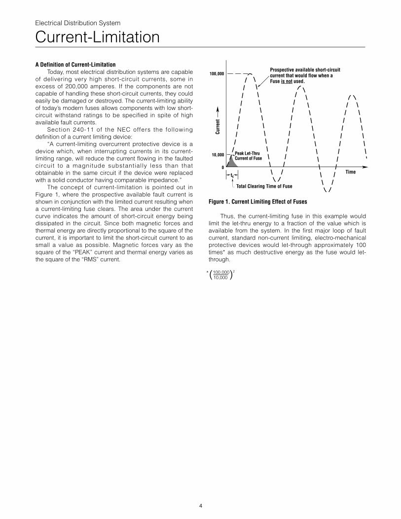
The concept of current-limitation is pointed out inFigure 1, where the prospective available fault current isshown in conjunction with the limited current resulting whena current-limiting fuse clears. The area under the currentcurve indicates the amount of short-circuit energy beingdissipated in the circuit. Since both magnetic forces andthermal energy are directly proportional to the square of thecurrent, it is important to limit the short-circuit current to assmall a value as possible. Magnetic forces vary as thesquare of the “PEAK” current and thermal energy varies asthe square of the “RMS” current.
4
Figure 1. Current Limiting Effect of Fuses
Thus, the current-limiting fuse in this example wouldlimit the let-thru energy to a fraction of the value which isavailable from the system. In the first major loop of faultcurrent, standard non-current limiting, electro-mechanicalprotective devices would let-through approximately 100times* as much destructive energy as the fuse would let-through.
(100,000)2
10,000
Prospective available short-circuitcurrent that would flow when a Fuse is not used.
100,000
Peak Let-ThruCurrent of Fuse
tc
10,000
Time
Total Clearing Time of Fuse
0
Curr
ent
*
Electrical Distribution System
Current-Limitation
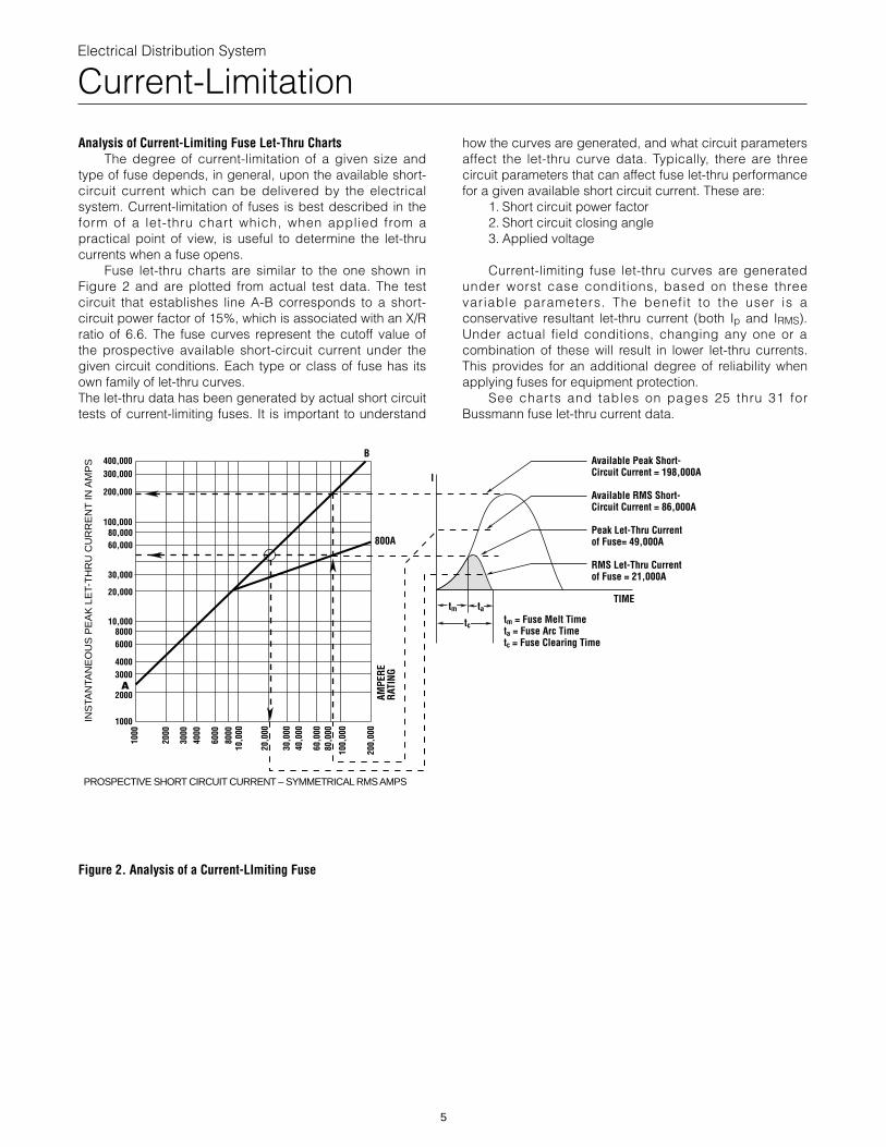
Analysis of Current-Limiting Fuse Let-Thru ChartsThe degree of current-limitation of a given size and
type of fuse depends, in general, upon the available short-circuit current which can be delivered by the electricalsystem. Current-limitation of fuses is best described in theform of a let-thru chart which, when applied from apractical point of view, is useful to determine the let-thrucurrents when a fuse opens.
Fuse let-thru charts are similar to the one shown inFigure 2 and are plotted from actual test data. The testcircuit that establishes line A-B corresponds to a short-circuit power factor of 15%, which is associated with an X/Rratio of 6.6. The fuse curves represent the cutoff value ofthe prospective available short-circuit current under thegiven circuit conditions. Each type or class of fuse has itsown family of let-thru curves.The let-thru data has been generated by actual short circuittests of current-limiting fuses. It is important to understand
5
how the curves are generated, and what circuit parametersaffect the let-thru curve data. Typically, there are threecircuit parameters that can affect fuse let-thru performancefor a given available short circuit current. These are:
1. Short circuit power factor2. Short circuit closing angle3. Applied voltage
Current-limiting fuse let-thru curves are generatedunder worst case conditions, based on these threevariable parameters. The benefit to the user is aconservative resultant let-thru current (both Ip and IRMS).Under actual field conditions, changing any one or acombination of these will result in lower let-thru currents.This provides for an additional degree of reliability whenapplying fuses for equipment protection.
See charts and tables on pages 25 thru 31 forBussmann fuse let-thru current data.
AMPE
RERA
TING
800A
PROSPECTIVE SHORT CIRCUIT CURRENT – SYMMETRICAL RMS AMPS
INS
TAN
TAN
EO
US
PE
AK
LE
T-T
HR
U C
UR
RE
NT
IN A
MP
S
1000
2000
3000
4000
6000
8000
10,0
00
20,0
00
30,0
0040
,000
60,0
0080
,000
100,
000
200,
000
I
A
B400,000300,000
200,000
100,00080,00060,000
30,000
20,000
10,00080006000
40003000
2000
1000
Available Peak Short-Circuit Current = 198,000A
Available RMS Short- Circuit Current = 86,000A
Peak Let-Thru Currentof Fuse= 49,000A
RMS Let-Thru Current of Fuse = 21,000A
tm = Fuse Melt Timeta = Fuse Arc Timetc = Fuse Clearing Time
tc
tm taTIME
Figure 2. Analysis of a Current-LImiting Fuse
Electrical Distribution System
Let-Thru Data Pertinent to Equipment Withstand
Prior to using the Fuse Let-Thru Charts, it must bedetermined what let-thru data is pertinent to equipmentwithstand ratings.
Equipment withstand ratings can be described as:How Much Fault Current can the equipment handle, andfor How Long ? Based on standards presently available,the most important data which can be obtained from theFuse Let-Thru Charts and their physical effects are thefollowing:
A. Peak let-thru current - mechanical forcesB. Apparent prospective RMS symmetrical let-thru
current - heating effect
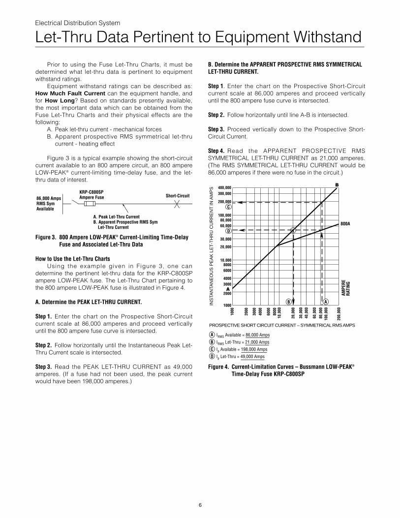
Figure 3 is a typical example showing the short-circuitcurrent available to an 800 ampere circuit, an 800 ampereLOW-PEAK® current-limiting time-delay fuse, and the let-thru data of interest.
Figure 3. 800 Ampere LOW-PEAK® Current-Limiting Time-DelayFuse and Associated Let-Thru Data
KRP-C800SPAmpere Fuse86,000 Amps
RMS SymAvailable
Short-Circuit
A. Peak Let-Thru CurrentB. Apparent Prospective RMS Sym Let-Thru Current
How to Use the Let-Thru ChartsUsing the example given in Figure 3, one can
determine the pertinent let-thru data for the KRP-C800SPampere LOW-PEAK fuse. The Let-Thru Chart pertaining tothe 800 ampere LOW-PEAK fuse is illustrated in Figure 4.
A. Determine the PEAK LET-THRU CURRENT.
Step 1. Enter the chart on the Prospective Short-Circuitcurrent scale at 86,000 amperes and proceed verticallyuntil the 800 ampere fuse curve is intersected.
Step 2. Follow horizontally until the Instantaneous Peak Let-Thru Current scale is intersected.
Step 3. Read the PEAK LET-THRU CURRENT as 49,000amperes. (If a fuse had not been used, the peak currentwould have been 198,000 amperes.)
6
B. Determine the APPARENT PROSPECTIVE RMS SYMMETRICALLET-THRU CURRENT.
Step 1. Enter the chart on the Prospective Short-Circuitcurrent scale at 86,000 amperes and proceed verticallyuntil the 800 ampere fuse curve is intersected.
Step 2. Follow horizontally until line A-B is intersected.
Step 3. Proceed vertically down to the Prospective Short-Circuit Current.
Step 4. Read the APPARENT PROSPECTIVE RMSSYMMETRICAL LET-THRU CURRENT as 21,000 amperes.(The RMS SYMMETRICAL LET-THRU CURRENT would be86,000 amperes if there were no fuse in the circuit.)
AMPE
RERA
TING
800A
INS
TAN
TAN
EO
US
PE
AK
LE
T-T
HR
U C
UR
RE
NT
IN A
MP
S
1000
2000
3000
4000
6000
8000
10,0
00
20,0
00
30,0
0040
,000
60,0
00
80,0
0010
0,00
0
200,
000
400,000300,000
200,000
100,00080,00060,000
30,000
20,000
10,00080006000
40003000
2000
1000
IRMS Available = 86,000 Amps
IRMS Let-Thru = 21,000 Amps
Ip Available = 198,000 Amps
Ip Let-Thru = 49,000 Amps
B
C
D
D
B A
C
A
A
PROSPECTIVE SHORT CIRCUIT CURRENT – SYMMETRICAL RMS AMPS
B
Figure 4. Current-Limitation Curves – Bussmann LOW-PEAK®
Time-Delay Fuse KRP-C800SP
Electrical Distribution System
A Practical Approach – Protecting System Components
Most electrical equipment has a withstand rating that isdefined in terms of an RMS Symmetrical-Short CircuitCurrent, and in some cases, Peak Let-Thru Current. Thesevalues have been established through short-circuit testingof that equipment according to an accepted industrystandard. Or, as is the case with conductors, the withstandrating is based on a mathematical calculation and is alsoexpressed in an RMS short circuit current.
If both the let-thru currents (I RMS and I p) of thecurrent limiting fuse and the time it takes to clear thefault are less than the withstand rating of the electricalcomponent, then that component will be protected fromshort-circuit damage.
Protecting System Components
A. Wire and Cable
7
The following components wil l be analyzed byestablishing the short-circuit withstand data of eachcomponent and then selecting the proper current limitingfuses for protection:
A. Wire and CableB. Bus (Busway, Switchboards, Motor Control Centers
and Panelboards)C. Low-Voltage Motor ControllersD. Circuit BreakersE. Low-Voltage TransformersF. BallastsG. Transfer SwitchesH. HVAC Equipment
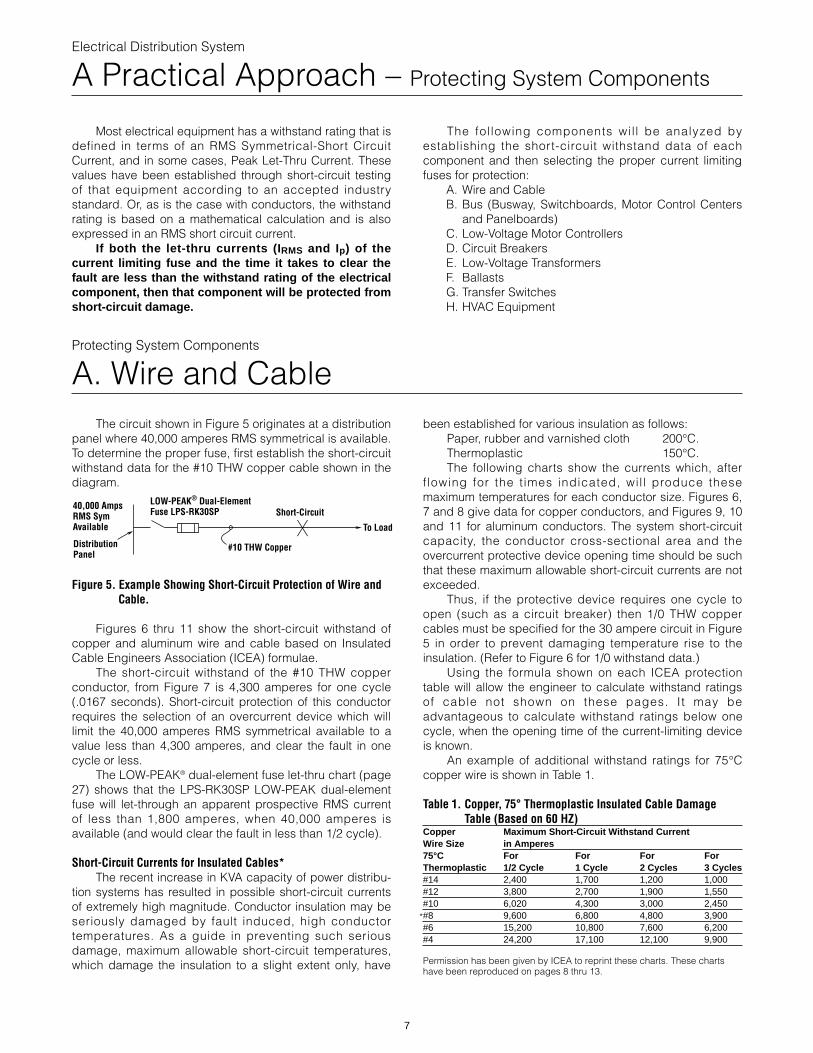
The circuit shown in Figure 5 originates at a distributionpanel where 40,000 amperes RMS symmetrical is available.To determine the proper fuse, first establish the short-circuitwithstand data for the #10 THW copper cable shown in thediagram.
Figure 5. Example Showing Short-Circuit Protection of Wire andCable.
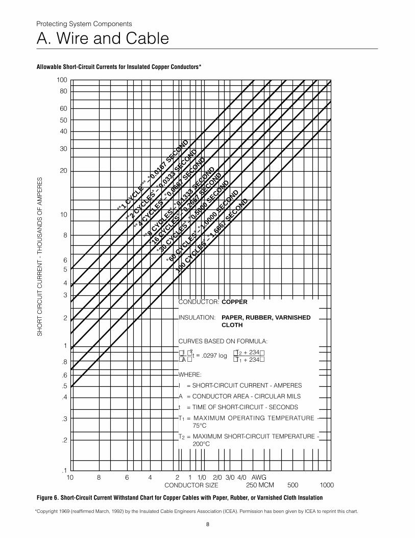
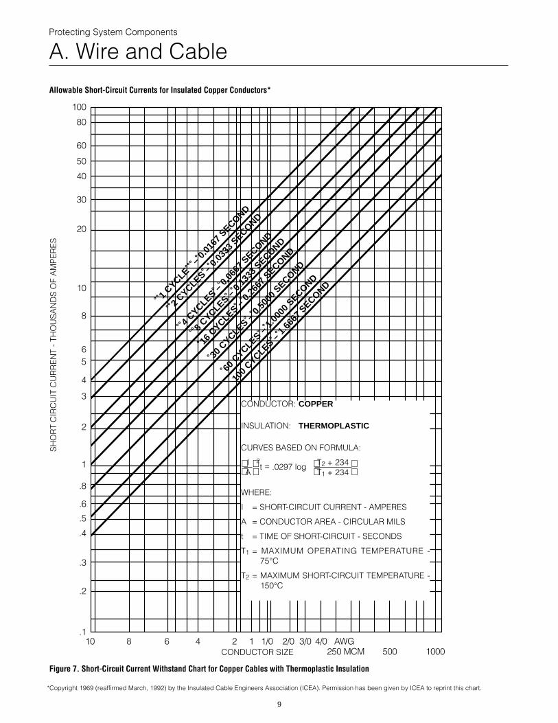
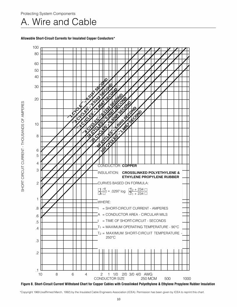
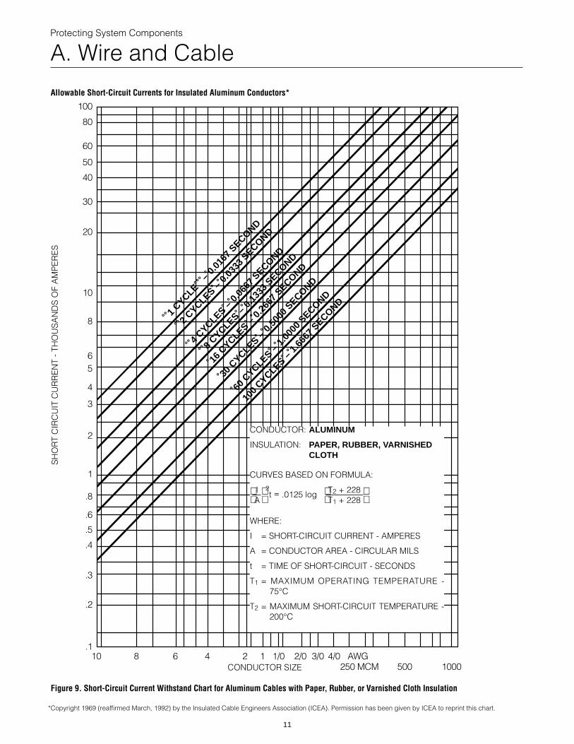
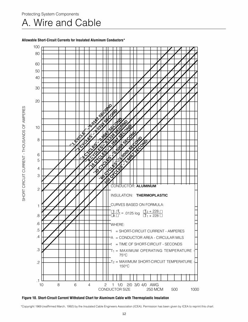
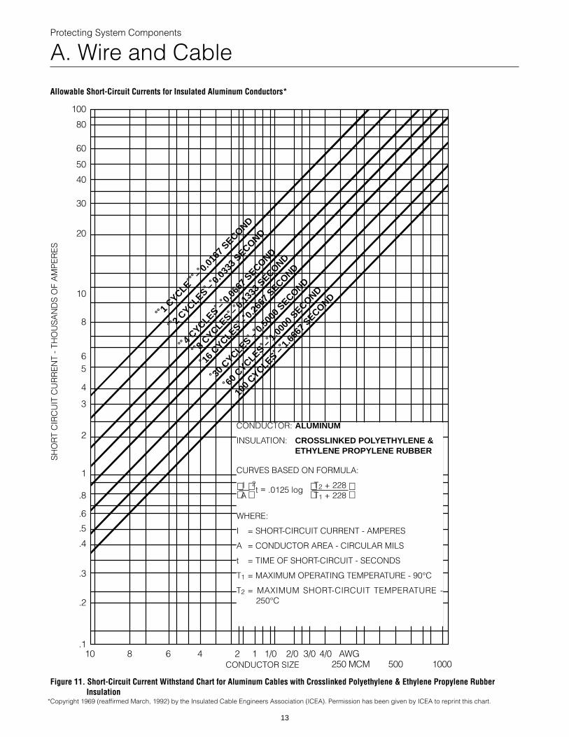
Figures 6 thru 11 show the short-circuit withstand ofcopper and aluminum wire and cable based on InsulatedCable Engineers Association (ICEA) formulae.
The short-circuit withstand of the #10 THW copperconductor, from Figure 7 is 4,300 amperes for one cycle(.0167 seconds). Short-circuit protection of this conductorrequires the selection of an overcurrent device which willlimit the 40,000 amperes RMS symmetrical available to avalue less than 4,300 amperes, and clear the fault in onecycle or less.
The LOW-PEAK® dual-element fuse let-thru chart (page27) shows that the LPS-RK30SP LOW-PEAK dual-elementfuse will let-through an apparent prospective RMS currentof less than 1,800 amperes, when 40,000 amperes isavailable (and would clear the fault in less than 1/2 cycle).
Short-Circuit Currents for Insulated Cables*The recent increase in KVA capacity of power distribu-
tion systems has resulted in possible short-circuit currentsof extremely high magnitude. Conductor insulation may beseriously damaged by fault induced, high conductortemperatures. As a guide in preventing such seriousdamage, maximum allowable short-circuit temperatures,which damage the insulation to a slight extent only, have
LOW-PEAK® Dual-ElementFuse LPS-RK30SP
40,000 AmpsRMS SymAvailable
Short-Circuit
DistributionPanel
To Load
#10 THW Copper
been established for various insulation as follows:Paper, rubber and varnished cloth 200°C.Thermoplastic 150°C.The following charts show the currents which, after
flowing for the times indicated, wil l produce thesemaximum temperatures for each conductor size. Figures 6,7 and 8 give data for copper conductors, and Figures 9, 10and 11 for aluminum conductors. The system short-circuitcapacity, the conductor cross-sectional area and theovercurrent protective device opening time should be suchthat these maximum allowable short-circuit currents are notexceeded.
Thus, if the protective device requires one cycle toopen (such as a circuit breaker) then 1/0 THW coppercables must be specified for the 30 ampere circuit in Figure5 in order to prevent damaging temperature rise to theinsulation. (Refer to Figure 6 for 1/0 withstand data.)
Using the formula shown on each ICEA protectiontable will allow the engineer to calculate withstand ratingsof cable not shown on these pages. It may beadvantageous to calculate withstand ratings below onecycle, when the opening time of the current-limiting deviceis known.
An example of additional withstand ratings for 75°Ccopper wire is shown in Table 1.
Table 1. Copper, 75° Thermoplastic Insulated Cable Damage Table (Based on 60 HZ)
Copper Maximum Short-Circuit Withstand CurrentWire Size in Amperes75°C For For For ForThermoplastic 1/2 Cycle 1 Cycle 2 Cycles 3 Cycles#14 2,400 1,700 1,200 1,000#12 3,800 2,700 1,900 1,550#10 6,020 4,300 3,000 2,450#8 9,600 6,800 4,800 3,900#6 15,200 10,800 7,600 6,200#4 24,200 17,100 12,100 9,900
Permission has been given by ICEA to reprint these charts. These chartshave been reproduced on pages 8 thru 13.
*
Protecting System Components
A. Wire and Cable
100
80
60
50
40
30
20
10
8
65
4
3
2
1
.8
.6
.5
.4
.3
.2
.110 8 6 4 2 1 1/0 2/0
1CYCLE
– 0.
0167
SECOND
2CYCLES –
0.0
333
SECOND
4CYCLES –
0.0
667
SECOND
8CYCLES –
0.1
333
SECOND
16
CYCLES – 0
.266
7SECOND
30
CYCLES – 0
.500
0SECON
60
CYCLES – 1
.000
0SEC
100
CYCLES – 1
.666
7
Allowable Short-Circuit Currents for Insulated Copper Conductors*
Figure 6. Short-Circuit Current Withstand Chart for Copper Cables with Pape
SH
OR
T C
IRC
UIT
CU
RR
EN
T -
THO
US
AN
DS
OF
AM
PE
RE
S
CONDUCTOR SIZE
*Copyright 1969 (reaffirmed March, 1992) by the Insulated Cable Engineers Association (I
CONDUCTOR: C
INSULATION: PC
CURVES BASED
I 2t = .0297 log A
WHERE:
I = SHORT-CIRC
A = CONDUCTO
t = TIME OF SH
T1 = MAXIMUM75°C
T2 = MAXIMUM S200°C
3/0 4/0 AWG250 MCM 500 1000
DOND
SECOND
r, Rubber, or Varnished Cloth Insulation
CEA). Permission has been given by ICEA to reprint this chart.
OPPER
APER, RUBBER, VARNISHED LOTH
ON FORMULA:
T2 + 234 T1 + 234
UIT CURRENT - AMPERES
R AREA - CIRCULAR MILS
ORT-CIRCUIT - SECONDS
OPERATING TEMPERATURE -
HORT-CIRCUIT TEMPERATURE -
8
Protecting System Components
A. Wire and Cable
100
80
60
50
40
30
20
10
8
65
4
3
2
1
.8
.6
.5
.4
.3
.2
.110 8 6 4 2 1 1/0 2/0 3
1CYCLE
– 0.
0167
SECOND
2CYCLES –
0.0
333
SECOND
4CYCLES –
0.0
667
SECOND
8CYCLES –
0.1
333
SECOND
16
CYCLES – 0
.266
7SECOND
30
CYCLES – 0
.500
0SECOND
60
CYCLES – 1
.000
0SECO
100
CYCLES – 1
.666
7S
Allowable Short-Circuit Currents for Insulated Copper Conductors*
Figure 7. Short-Circuit Current Withstand Chart for Copper Cables with Therm
SH
OR
T C
IRC
UIT
CU
RR
EN
T -
THO
US
AN
DS
OF
AM
PE
RE
S
CONDUCTOR SIZE
*Copyright 1969 (reaffirmed March, 1992) by the Insulated Cable Engineers Association (IC
CONDUCTOR: C
INSULATION: TH
CURVES BASED
I 2t = .0297 log A
WHERE:
I = SHORT-CIRC
A = CONDUCTO
t = TIME OF SH
T1 = MAXIMUM 75°C
T2 = MAXIMUM S150°C
/0 4/0 AWG250 MCM 500 1000
NDECOND
oplastic Insulation
EA). Permission has been given by ICEA to reprint this chart.
OPPER
ERMOPLASTIC
ON FORMULA:
T2 + 234 T1 + 234
UIT CURRENT - AMPERES
R AREA - CIRCULAR MILS
ORT-CIRCUIT - SECONDS
OPERATING TEMPERATURE -
HORT-CIRCUIT TEMPERATURE -
9
Protecting System Components
A. Wire and Cable
100
80
60
50
40
30
20
10
8
65
4
3
2
1
.8
.6
.5
.4
.3
.2
.110 8 6 4 2 1 1/0 2/0
1CYCLE
– 0.
0167
SECOND
2CYCLES –
0.0
333
SECOND
4CYCLES –
0.0
667
SECOND
8CYCLES –
0.1
333
SECOND
16
CYCLES – 0
.266
7SECOND
30
CYCLES – 0
.500
0SECO
60
CYCLES – 1
.000
0S
100
CYCLES – 1
.66
Allowable Short-Circuit Currents for Insulated Copper Conductors*
Figure 8. Short-Circuit Current Withstand Chart for Copper Cables with Cros
SH
OR
T C
IRC
UIT
CU
RR
EN
T -
THO
US
AN
DS
OF
AM
PE
RE
S
CONDUCTOR SIZE
*Copyright 1969 (reaffirmed March, 1992) by the Insulated Cable Engineers Association
CONDUCTOR: CO
INSULATION: CRET
CURVES BASED O
I 2t = .0297 log A
WHERE:
I = SHORT-CIRCU
A = CONDUCTOR
t = TIME OF SHO
T1 = MAXIMUM OP
T2 = MAXIMUM S250°C
3/0 4/0 AWG250 MCM 500 1000
NDECOND
67SECOND
slinked Polyethylene & Ethylene Propylene Rubber Insulation
(ICEA). Permission has been given by ICEA to reprint this chart.
PPER
OSSLINKED POLYETHYLENE & HYLENE PROPYLENE RUBBER
N FORMULA:
T2 + 234 T1 + 234
IT CURRENT - AMPERES
AREA - CIRCULAR MILS
RT-CIRCUIT - SECONDS
ERATING TEMPERATURE - 90°C
HORT-CIRCUIT TEMPERATURE -
10
Protecting System Components
A. Wire and Cable
100
80
60
50
40
30
20
10
8
65
4
3
2
1
.8
.6
.5
.4
.3
.2
.110 8 6 4 2 1 1/0 2/0
1CYCLE
– 0.
0167
SECOND
2CYCLES –
0.0
333
SECOND
4CYCLES –
0.0
667
SECOND
8CYCLES –
0.1
333
SECOND
16
CYCLES – 0
.266
7SECOND
30
CYCLES – 0
.500
0SECO
60
CYCLES – 1
.000
0S
100
CYCLES – 1
.66
Allowable Short-Circuit Currents for Insulated Aluminum Conductors*
Figure 9. Short-Circuit Current Withstand Chart for Aluminum Cables with P
SH
OR
T C
IRC
UIT
CU
RR
EN
T -
THO
US
AN
DS
OF
AM
PE
RE
S
CONDUCTOR SIZE
*Copyright 1969 (reaffirmed March, 1992) by the Insulated Cable Engineers Association
CONDUCTOR:
INSULATION:
CURVES BASE
I 2t = .0125 A
WHERE:
I = SHORT-CI
A = CONDUC
t = TIME OF S
T1 = MAXIMU75°C
T2 = MAXIMUM200°C
3/0 4/0 AWG250 MCM 500 1000
NDECOND
67SECOND
aper, Rubber, or Varnished Cloth Insulation
(ICEA). Permission has been given by ICEA to reprint this chart.
ALUMINUM
PAPER, RUBBER, VARNISHED CLOTH
D ON FORMULA:
log T2 + 228 T1 + 228
RCUIT CURRENT - AMPERES
TOR AREA - CIRCULAR MILS
HORT-CIRCUIT - SECONDS
M OPERATING TEMPERATURE -
SHORT-CIRCUIT TEMPERATURE -
11
Protecting System Components
A. Wire and Cable
100
80
60
50
40
30
20
10
8
65
4
3
2
1
.8
.6
.5
.4
.3
.2
.110 8 6 4 2 1 1/0 2/0
1CYCLE
– 0.
0167
SECOND
2CYCLES –
0.0
333
SECOND
4CYCLES –
0.0
667
SECOND
8CYCLES –
0.1
333
SECOND
16
CYCLES – 0
.266
7SECOND
30
CYCLES – 0
.500
0SECO
60
CYCLES – 1
.000
0SE
100
CYCLES – 1
.666
Allowable Short-Circuit Currents for Insulated Aluminum Conductors*
Figure 10. Short-Circuit Current Withstand Chart for Aluminum Cable with
SH
OR
T C
IRC
UIT
CU
RR
EN
T -
THO
US
AN
DS
OF
AM
PE
RE
S
CONDUCTOR SIZE
*Copyright 1969 (reaffirmed March, 1992) by the Insulated Cable Engineers Association
CONDUCTOR
INSULATION
CURVES BAS
I 2t = .0125 A
WHERE:
I = SHORT-
A = CONDU
t = TIME OF
T1 = MAXIM75°C
T2 = MAXIMU150°C
3/0 4/0 AWG250 MCM 500 1000
NDCOND
7SECOND
Thermoplastic Insulation
(ICEA). Permission has been given by ICEA to reprint this chart.
: ALUMINUM
: THERMOPLASTIC
ED ON FORMULA:
log T2 + 228 T1 + 228
CIRCUIT CURRENT - AMPERES
CTOR AREA - CIRCULAR MILS
SHORT-CIRCUIT - SECONDS
UM OPERATING TEMPERATURE -
M SHORT-CIRCUIT TEMPERATURE -
12
Protecting System Components
A. Wire and Cable
100
80
60
50
40
30
20
10
8
65
4
3
2
1
.8
.6
.5
.4
.3
.2
.110 8 6 4 2 1 1/0 2/0 3
1CYCLE
– 0.
0167
SECOND
2CYCLES –
0.0
333
SECOND
4CYCLES –
0.0
667
SECOND
8CYCLES –
0.1
333
SECOND
16
CYCLES – 0
.266
7SECOND
30
CYCLES – 0
.500
0SECOND
60
CYCLES – 1
.000
0SEC
100
CYCLES – 1
.666
7
Allowable Short-Circuit Currents for Insulated Aluminum Conductors*
Figure 11. Short-Circuit Current Withstand Chart for Aluminum Cables withInsulation
SH
OR
T C
IRC
UIT
CU
RR
EN
T -
THO
US
AN
DS
OF
AM
PE
RE
S
CONDUCTOR SIZE
*Copyright 1969 (reaffirmed March, 1992) by the Insulated Cable Engineers Association
CONDUCTOR: AL
INSULATION: CRET
CURVES BASED O
I 2t = .0125 log A
WHERE:
I = SHORT-CIRC
A = CONDUCTOR
t = TIME OF SHO
T1 = MAXIMUM OP
T2 = MAXIMUM S250°C
/0 4/0 AWG250 MCM 500 1000
ONDSECOND
Crosslinked Polyethylene & Ethylene Propylene Rubber
(ICEA). Permission has been given by ICEA to reprint this chart.
UMINUM
OSSLINKED POLYETHYLENE & HYLENE PROPYLENE RUBBER
N FORMULA:
T2 + 228 T1 + 228
UIT CURRENT - AMPERES
AREA - CIRCULAR MILS
RT-CIRCUIT - SECONDS
ERATING TEMPERATURE - 90°C
HORT-CIRCUIT TEMPERATURE -
13
Protecting System Components
A. Wire and Cable
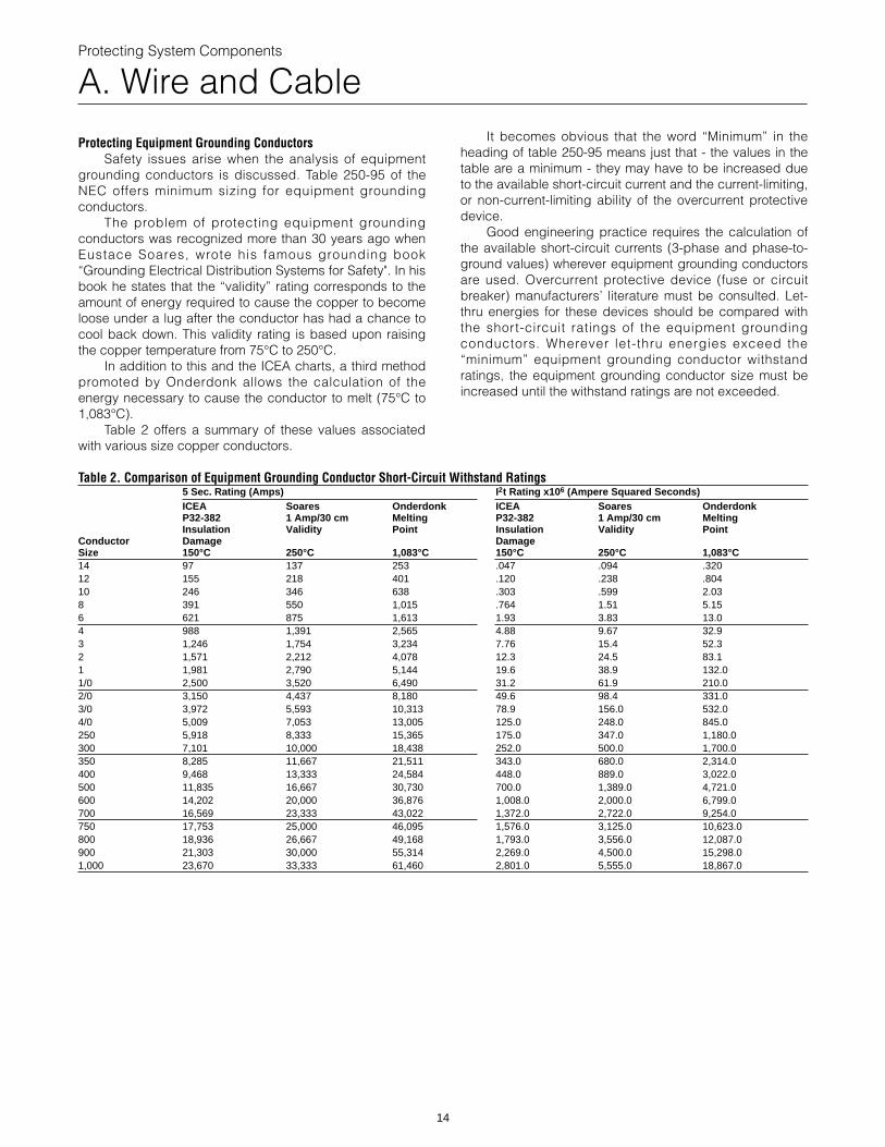
Protecting Equipment Grounding ConductorsSafety issues arise when the analysis of equipment
grounding conductors is discussed. Table 250-95 of theNEC offers minimum sizing for equipment groundingconductors.
The problem of protecting equipment groundingconductors was recognized more than 30 years ago whenEustace Soares, wrote his famous grounding book“Grounding Electrical Distribution Systems for Safety". In hisbook he states that the “validity” rating corresponds to theamount of energy required to cause the copper to becomeloose under a lug after the conductor has had a chance tocool back down. This validity rating is based upon raisingthe copper temperature from 75°C to 250°C.
In addition to this and the ICEA charts, a third methodpromoted by Onderdonk allows the calculation of theenergy necessary to cause the conductor to melt (75°C to1,083°C).
Table 2 offers a summary of these values associatedwith various size copper conductors.
It becomes obvious that the word “Minimum” in theheading of table 250-95 means just that - the values in thetable are a minimum - they may have to be increased dueto the available short-circuit current and the current-limiting,or non-current-limiting ability of the overcurrent protectivedevice.
Good engineering practice requires the calculation ofthe available short-circuit currents (3-phase and phase-to-ground values) wherever equipment grounding conductorsare used. Overcurrent protective device (fuse or circuitbreaker) manufacturers’ literature must be consulted. Let-thru energies for these devices should be compared withthe short-circuit ratings of the equipment groundingconductors. Wherever let-thru energies exceed the“minimum” equipment grounding conductor withstandratings, the equipment grounding conductor size must beincreased until the withstand ratings are not exceeded.
Table 2. Comparison of Equipment Grounding Conductor Short-Circuit Withstand Ratings5 Sec. Rating (Amps) I 2t Rating xICEA Soares Onderdonk ICEAP32-382 1 Amp/30 cm Melting P32-382Insulation Validity Point Insulation
Conductor Damage DamageSize 150°C 250°C 1,083°C 150°C14 97 137 253 .04712 155 218 401 .12010 246 346 638 .3038 391 550 1,015 .7646 621 875 1,613 1.934 988 1,391 2,565 4.883 1,246 1,754 3,234 7.762 1,571 2,212 4,078 12.31 1,981 2,790 5,144 19.61/0 2,500 3,520 6,490 31.22/0 3,150 4,437 8,180 49.63/0 3,972 5,593 10,313 78.94/0 5,009 7,053 13,005 125.0250 5,918 8,333 15,365 175.0300 7,101 10,000 18,438 252.0350 8,285 11,667 21,511 343.0400 9,468 13,333 24,584 448.0500 11,835 16,667 30,730 700.0600 14,202 20,000 36,876 1,008.0700 16,569 23,333 43,022 1,372.0750 17,753 25,000 46,095 1,576.0800 18,936 26,667 49,168 1,793.0900 21,303 30,000 55,314 2,269.01,000 23,670 33,333 61,460 2,801.0
10 6 (Ampere Squared Seconds)Soares Onderdonk1 Amp/30 cm Melting
Validity Point
250°C 1,083°C.094 .320.238 .804.599 2.031.51 5.153.83 13.09.67 32.915.4 52.324.5 83.138.9 132.061.9 210.098.4 331.0156.0 532.0248.0 845.0347.0 1,180.0500.0 1,700.0680.0 2,314.0889.0 3,022.01,389.0 4,721.02,000.0 6,799.02,722.0 9,254.03,125.0 10,623.03,556.0 12,087.04,500.0 15,298.05,555.0 18,867.0
14
Protecting System Components
B. Bus Short-Circuit Rating and Bracing Requirements
Bus Short-Circuit Rating Requirements When Protected byCurrent-Limiting Fuses
NEMA Standards require that busways have asymmetrical short-circuit withstand rating at least as greatas the average available symmetrical short-circuit current.*
Since the short-circuit ratings of busways areestablished on the basis of minimum three-cycle durationtests, these ratings will not apply unless the protectivedevice used will remove the fault within three cycles orless.*
BUSWAYS MAY BE USED ON CIRCUITS HAVINGAVAILABLE SHORT-CIRCUIT CURRENTS GREATER THANTHE BUSWAY RATING WHEN PROPERLY COORDINATED,AND RATED WITH CURRENT-LIMITING DEVICES.*
If a busway has been listed or labeled for a maximumshort-circuit current with a specific overcurrent device, itcannot be used where greater fault currents are availablewithout violating the listing or labeling. If a busway hasbeen listed or labeled for a maximum short-circuit currentwithout a specific overcurrent device (i.e., for three cycles),current-limiting fuses can be used to reduce the availableshort-circuit current to within the withstand rating of thebusway.
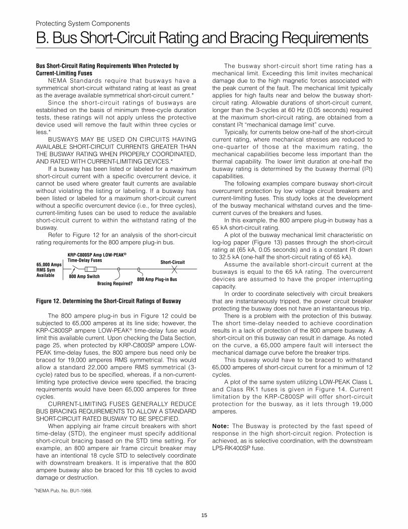
Refer to Figure 12 for an analysis of the short-circuitrating requirements for the 800 ampere plug-in bus.
800 Amp Switch
65,000 AmpsRMS SymAvailable
Short-Circuit
800 Amp Plug-in BusBracing Required?
KRP-C800SP Amp LOW-PEAK® Time-Delay Fuses
Figure 12. Determining the Short-Circuit Ratings of Busway
The 800 ampere plug-in bus in Figure 12 could besubjected to 65,000 amperes at its line side; however, theKRP-C800SP ampere LOW-PEAK® time-delay fuse wouldlimit this available current. Upon checking the Data Section,page 25, when protected by KRP-C800SP ampere LOW-PEAK time-delay fuses, the 800 ampere bus need only bebraced for 19,000 amperes RMS symmetrical. This wouldallow a standard 22,000 ampere RMS symmetrical (3-cycle) rated bus to be specified, whereas, if a non-current-limiting type protective device were specified, the bracingrequirements would have been 65,000 amperes for threecycles.
CURRENT-LIMITING FUSES GENERALLY REDUCEBUS BRACING REQUIREMENTS TO ALLOW A STANDARDSHORT-CIRCUIT RATED BUSWAY TO BE SPECIFIED.
When applying air frame circuit breakers with shorttime-delay (STD), the engineer must specify additionalshort-circuit bracing based on the STD time setting. Forexample, an 800 ampere air frame circuit breaker mayhave an intentional 18 cycle STD to selectively coordinatewith downstream breakers. It is imperative that the 800ampere busway also be braced for this 18 cycles to avoiddamage or destruction.
NEMA Pub. No. BU1-1988.*
15
The busway short-circuit short time rating has amechanical limit. Exceeding this limit invites mechanicaldamage due to the high magnetic forces associated withthe peak current of the fault. The mechanical limit typicallyapplies for high faults near and below the busway short-circuit rating. Allowable durations of short-circuit current,longer than the 3-cycles at 60 Hz (0.05 seconds) requiredat the maximum short-circuit rating, are obtained from aconstant I2t “mechanical damage limit” curve.
Typically, for currents below one-half of the short-circuitcurrent rating, where mechanical stresses are reduced toone-quarter of those at the maximum rating, themechanical capabilities become less important than thethermal capability. The lower limit duration at one-half thebusway rating is determined by the busway thermal (I2t)capabilities.
The following examples compare busway short-circuitovercurrent protection by low voltage circuit breakers andcurrent-limiting fuses. This study looks at the developmentof the busway mechanical withstand curves and the time-current curves of the breakers and fuses.
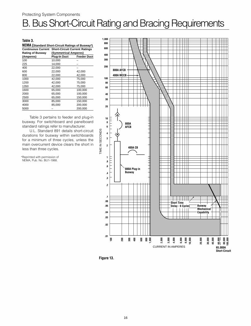
In this example, the 800 ampere plug-in busway has a65 kA short-circuit rating.
A plot of the busway mechanical limit characteristic onlog-log paper (Figure 13) passes through the short-circuitrating at (65 kA, 0.05 seconds) and is a constant I2t downto 32.5 kA (one-half the short-circuit rating of 65 kA).
Assume the available short-circuit current at thebusways is equal to the 65 kA rating. The overcurrentdevices are assumed to have the proper interruptingcapacity.
In order to coordinate selectively with circuit breakersthat are instantaneously tripped, the power circuit breakerprotecting the busway does not have an instantaneous trip.
There is a problem with the protection of this busway.The short time-delay needed to achieve coordinationresults in a lack of protection of the 800 ampere busway. Ashort-circuit on this busway can result in damage. As notedon the curve, a 65,000 ampere fault will intersect themechanical damage curve before the breaker trips.
This busway would have to be braced to withstand65,000 amperes of short-circuit current for a minimum of 12cycles.
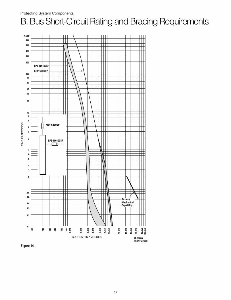
A plot of the same system utilizing LOW-PEAK Class Land Class RK1 fuses is given in Figure 14. Currentlimitation by the KRP-C800SP will offer short-circuitprotection for the busway, as it lets through 19,000amperes.
Note: The Busway is protected by the fast speed ofresponse in the high short-circuit region. Protection isachieved, as is selective coordination, with the downstreamLPS-RK400SP fuse.
Protecting System Components
B. Bus Short-Circuit Rating and Bracing Requirements
Table 3.NEMA (Standard Short-Circuit Ratings of Busway*)Continuous Current Short-Circuit Current RatingsRating of Busway (Symmetrical Amperes)(Amperes) Plug-In Duct Feeder Duct100 10,000 –225 14,000 –400 22,000 –600 22,000 42,000800 22,000 42,0001000 42,000 75,0001200 42,000 75,0001350 42,000 75,0001600 65,000 100,0002000 65,000 100,0002500 65,000 150,0003000 85,000 150,0004000 85,000 200,0005000 – 200,000
Table 3 pertains to feeder and plug-inbusway. For switchboard and panelboardstandard ratings refer to manufacturer.
U.L. Standard 891 details short-circuitdurations for busway within switchboardsfor a minimum of three cycles, unless themain overcurrent device clears the short inless than three cycles.
Reprinted with permission ofNEMA, Pub. No. BU1-1988.
*
60,0
00
800AAFCB
800A Plug-in Busway
400A CB
800A AFCB
400A MCCB
Short TimeDelay - 6 Cycles Busway
MechanicalCapability
65,000AShort-Circuit
100,
000
80,0
00
10,0
00
40,0
00
30,0
00
20,0
00
8,00
0
6,00
0
4,00
0
3,00
0
2,00
0
1,00
080
0
600
400
300
200
100
CURRENT IN AMPERES
1,000
800
600
400
300
200
100
80
60
40
30
20
108
6
4
3
2
1
.8
.6
.4
.3
.2
.1
.08
.06
.04
.03
.02
.01
TIM
E IN
SE
CO
ND
S
Figure 13.
16
Protecting System Components
B. Bus Short-Circuit Rating and Bracing Requirements
60,0
00
100,
000
80,0
00
10,0
00
40,0
00
30,0
00
20,0
00
8,00
0
6,00
0
4,00
0
3,00
0
2,00
0
1,00
0
800
600
400
300
200
100
CURRENT IN AMPERES
LPS-RK400SP
KRP-C800SP
BuswayMechanicalCapability
65,000AShort-Circuit
KRP-C800SP
LPS-RK400SP
TIM
E IN
SE
CO
ND
S
1,000
800
600
400
300
200
100
80
60
40
30
20
10
8
6
4
3
2
1
.8
.6
.4
.3
.2
.1
.08
.06
.04
.03
.02
.01
Figure 14.
17
Protecting System Components
C. Low Voltage Motor Controllers
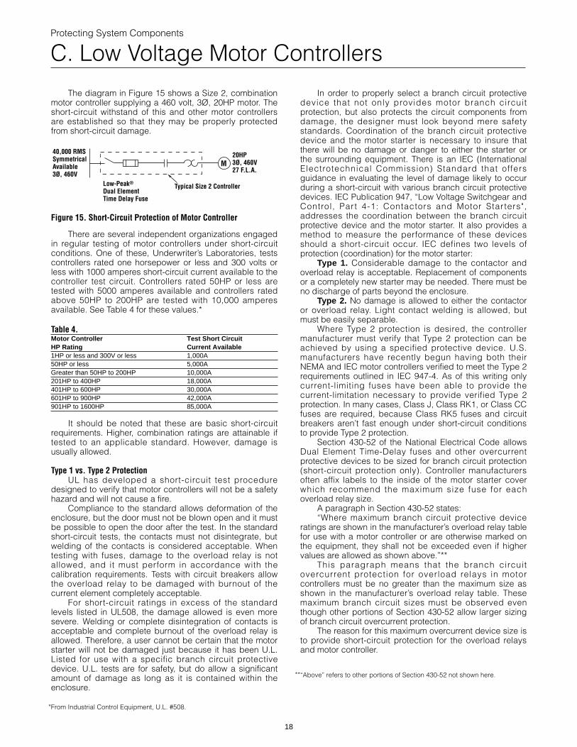
The diagram in Figure 15 shows a Size 2, combinationmotor controller supplying a 460 volt, 3Ø, 20HP motor. Theshort-circuit withstand of this and other motor controllersare established so that they may be properly protectedfrom short-circuit damage.
Figure 15. Short-Circuit Protection of Motor Controller
There are several independent organizations engagedin regular testing of motor controllers under short-circuitconditions. One of these, Underwriter’s Laboratories, testscontrollers rated one horsepower or less and 300 volts orless with 1000 amperes short-circuit current available to thecontroller test circuit. Controllers rated 50HP or less aretested with 5000 amperes available and controllers ratedabove 50HP to 200HP are tested with 10,000 amperesavailable. See Table 4 for these values.*
Table 4.Motor Controller Test Short CircuitHP Rating Current Available1HP or less and 300V or less 1,000A50HP or less 5,000AGreater than 50HP to 200HP 10,000A201HP to 400HP 18,000A401HP to 600HP 30,000A601HP to 900HP 42,000A901HP to 1600HP 85,000A
It should be noted that these are basic short-circuitrequirements. Higher, combination ratings are attainable iftested to an applicable standard. However, damage isusually allowed.
M
Typical Size 2 ControllerLow-Peak®
Dual ElementTime Delay Fuse
20HP3Ø, 460V27 F.L.A.
40,000 RMS Symmetrical Available3Ø, 460V
Type 1 vs. Type 2 ProtectionUL has developed a short-circuit test procedure
designed to verify that motor controllers will not be a safetyhazard and will not cause a fire.
Compliance to the standard allows deformation of theenclosure, but the door must not be blown open and it mustbe possible to open the door after the test. In the standardshort-circuit tests, the contacts must not disintegrate, butwelding of the contacts is considered acceptable. Whentesting with fuses, damage to the overload relay is notallowed, and it must perform in accordance with thecalibration requirements. Tests with circuit breakers allowthe overload relay to be damaged with burnout of thecurrent element completely acceptable.
For short-circuit ratings in excess of the standardlevels listed in UL508, the damage allowed is even moresevere. Welding or complete disintegration of contacts isacceptable and complete burnout of the overload relay isallowed. Therefore, a user cannot be certain that the motorstarter will not be damaged just because it has been U.L.Listed for use with a specific branch circuit protectivedevice. U.L. tests are for safety, but do allow a significantamount of damage as long as it is contained within theenclosure.
From Industrial Control Equipment, U.L. #508.*
18
In order to properly select a branch circuit protectivedevice that not only provides motor branch circuitprotection, but also protects the circuit components fromdamage, the designer must look beyond mere safetystandards. Coordination of the branch circuit protectivedevice and the motor starter is necessary to insure thatthere will be no damage or danger to either the starter orthe surrounding equipment. There is an IEC (InternationalElectrotechnical Commission) Standard that offersguidance in evaluating the level of damage likely to occurduring a short-circuit with various branch circuit protectivedevices. IEC Publication 947, “Low Voltage Switchgear andControl, Part 4-1: Contactors and Motor Star ters",addresses the coordination between the branch circuitprotective device and the motor starter. It also provides amethod to measure the performance of these devicesshould a short-circuit occur. IEC defines two levels ofprotection (coordination) for the motor starter:
Type 1. Considerable damage to the contactor andoverload relay is acceptable. Replacement of componentsor a completely new starter may be needed. There must beno discharge of parts beyond the enclosure.
Type 2. No damage is allowed to either the contactoror overload relay. Light contact welding is allowed, butmust be easily separable.
Where Type 2 protection is desired, the controllermanufacturer must verify that Type 2 protection can beachieved by using a specified protective device. U.S.manufacturers have recently begun having both theirNEMA and IEC motor controllers verified to meet the Type 2requirements outlined in IEC 947-4. As of this writing onlycurrent-limiting fuses have been able to provide thecurrent-limitation necessary to provide verified Type 2protection. In many cases, Class J, Class RK1, or Class CCfuses are required, because Class RK5 fuses and circuitbreakers aren’t fast enough under short-circuit conditionsto provide Type 2 protection.
Section 430-52 of the National Electrical Code allowsDual Element Time-Delay fuses and other overcurrentprotective devices to be sized for branch circuit protection(short-circuit protection only). Controller manufacturersoften affix labels to the inside of the motor starter coverwhich recommend the maximum size fuse for eachoverload relay size.
A paragraph in Section 430-52 states:“Where maximum branch circuit protective device
ratings are shown in the manufacturer’s overload relay tablefor use with a motor controller or are otherwise marked onthe equipment, they shall not be exceeded even if highervalues are allowed as shown above.”**
This paragraph means that the branch circuitovercurrent protection for overload relays in motorcontrollers must be no greater than the maximum size asshown in the manufacturer’s overload relay table. Thesemaximum branch circuit sizes must be observed eventhough other portions of Section 430-52 allow larger sizingof branch circuit overcurrent protection.
The reason for this maximum overcurrent device size isto provide short-circuit protection for the overload relaysand motor controller.
“Above” refers to other portions of Section 430-52 not shown here.**
Protecting System Components
D. Molded Case Circuit Breakers
Until recently, molded case circuit breakers wereprotected the same way as other electrical equipment.Quicker acting circuit breakers, as well as test circuits thatcause short-circuit test parameters to change, haverequired additional considerations in recommendedprotection procedures.
As has been discussed previously, the two parametersIRMS and Ip, must be compared to the equipment withstandrating. The rule is simple: if the RMS and peak let-thru valueof the fuse are less than the equipment withstand rating,the equipment will be protected. This philosophy holds truefor various static components, such as wire and cable,busway, and motor star ters. This basic protectionrequirement is mandated in NEC Section 110-10. It will alsobe true for non-current-limiting circuit breakers when theiropening time is greater than one-half cycle.
In the past, as long as the fuse let-thru values wereless than the breaker’s interrupting rating, the system wasconsidered sound. THIS METHOD HAS A SOLID HISTORYOF SUCCESSFUL APPLICATIONS. However, due tochanges in circuit breaker design, the method may notalways work with today’s circuit breakers. Selecting acurrent-limiting fuse to protect a downstream molded casecircuit breaker has now become an increasingly morecomplex problem.
Quicker Operating Circuit BreakersSimply put, if the total clearing energy of a quicker
acting molded case circuit breaker is less than the meltingenergy of a larger upstream fuse, the molded case circuitbreaker will interrupt the full value of the system faultwithout the benefit of the fuse’s current-limiting effect. Thissituation can have catastrophic effects on the circuitbreaker as it tries to interrupt faults beyond its interruptingcapacity. Currently, there is no available engineeringmethod to predict protection of these faster breakers.
Molded Case Circuit Breakers - Agency Test ProceduresSome agency standards allow a unique test set-up for
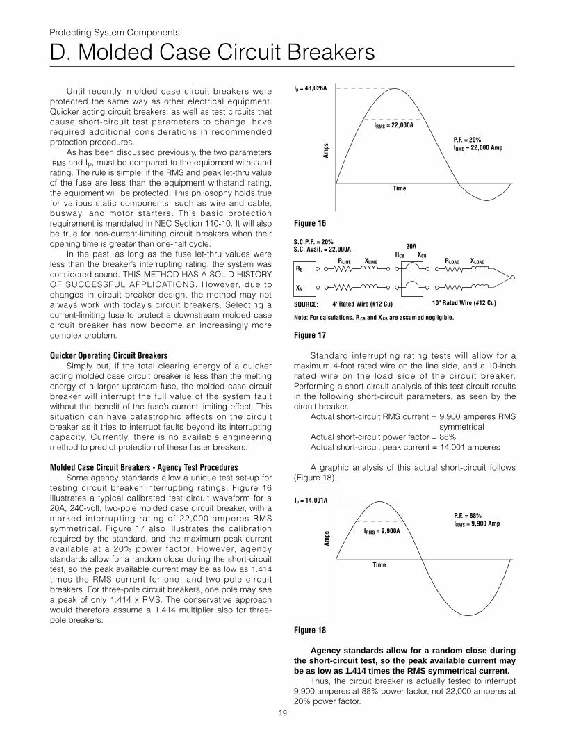
testing circuit breaker interrupting ratings. Figure 16illustrates a typical calibrated test circuit waveform for a20A, 240-volt, two-pole molded case circuit breaker, with amarked interrupting rating of 22,000 amperes RMSsymmetrical. Figure 17 also illustrates the calibrationrequired by the standard, and the maximum peak currentavailable at a 20% power factor. However, agencystandards allow for a random close during the short-circuittest, so the peak available current may be as low as 1.414times the RMS current for one- and two-pole circuitbreakers. For three-pole circuit breakers, one pole may seea peak of only 1.414 x RMS. The conservative approachwould therefore assume a 1.414 multiplier also for three-pole breakers.
19
Figure 16
Figure 17
Standard interrupting rating tests will allow for amaximum 4-foot rated wire on the line side, and a 10-inchrated wire on the load side of the circuit breaker.Performing a short-circuit analysis of this test circuit resultsin the following short-circuit parameters, as seen by thecircuit breaker.
Actual short-circuit RMS current = 9,900 amperes RMSsymmetrical
Actual short-circuit power factor = 88%Actual short-circuit peak current = 14,001 amperes
A graphic analysis of this actual short-circuit follows(Figure 18).
Amps
Time
P.F. = 20%IRMS = 22,000 Amp
Ip = 48,026A
IRMS = 22,000A
RLINE XLINE
RCB XCB
20A
RLOAD XLOADRS
XS
SOURCE: 4' Rated Wire (#12 Cu)
Note: For calculations, RCB and XCB are assumed negligible.
10" Rated Wire (#12 Cu)
S.C.P.F. = 20%S.C. Avail. = 22,000A
Figure 18
Agency standards allow for a random close duringthe short-circuit test, so the peak available current maybe as low as 1.414 times the RMS symmetrical current.
Thus, the circuit breaker is actually tested to interrupt9,900 amperes at 88% power factor, not 22,000 amperes at20% power factor.
Amps
Time
P.F. = 88%IRMS = 9,900 Amp
IRMS = 9,900A
Ip = 14,001A
Protecting System Components
D. Molded Case Circuit Breakers
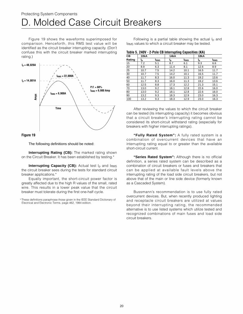
Figure 19 shows the waveforms superimposed forcomparison. Henceforth, this RMS test value will beidentified as the circuit breaker interrupting capacity. (Don’tconfuse this with the circuit breaker marked interruptingrating.)
Figure 19
The following definitions should be noted:
Interrupting Rating (CB): The marked rating shownon the Circuit Breaker. It has been established by testing.*
Interrupting Capacity (CB): Actual test Ip and IRMSthe circuit breaker sees during the tests for standard circuitbreaker applications.*
Equally important, the short-circuit power factor isgreatly affected due to the high R values of the small, ratedwire. This results in a lower peak value that the circuitbreaker must tolerate during the first one-half cycle.
These definitions paraphrase those given in the IEEE Standard Dictionary ofElectrical and Electronic Terms, page 462, 1984 edition.
Amps
Time
P.F. = 88%IRMS = 9,900 Amp
Ip = 48,026A
IRMS = 9,900A
Ip = 14,001A
IRMS = 22,000A
*
20
Following is a partial table showing the actual Ip andIRMS values to which a circuit breaker may be tested.
Table 5. 240V - 2-Pole CB Interrupting Capacities (KA)CB 10kA 14kA 18kARating I p IRMS Ip IRMS Ip IRMS
15 7.2 5.1 8.7 6.1 9.3 6.620 8.9 6.3 11.4 8.1 12.6 8.925 10.7 7.5 14.2 10.1 16.5 11.730 10.7 7.5 14.2 10.1 16.5 11.740 11.7 8.3 16.0 11.3 19.2 13.650 11.7 8.3 16.0 11.3 19.2 13.660 12.5 8.8 17.3 12.2 21.3 15.170 13.0 9.2 18.1 12.8 22.6 16.080 13.0 9.2 18.1 12.8 22.6 16.090 13.2 9.3 18.3 12.9 23.0 16.3100 13.2 9.3 18.3 12.9 23.0 16.3
After reviewing the values to which the circuit breakercan be tested (its interrupting capacity) it becomes obviousthat a circuit breaker’s interrupting rating cannot beconsidered its short-circuit withstand rating (especially forbreakers with higher interrupting ratings).
“Fully Rated System”: A fully rated system is acombination of overcurrent devices that have aninterrupting rating equal to or greater than the availableshort-circuit current.
“Series Rated System”: Although there is no officialdefinition, a series rated system can be described as acombination of circuit breakers or fuses and breakers thatcan be applied at available fault levels above theinterrupting rating of the load side circuit breakers, but notabove that of the main or line side device (formerly knownas a Cascaded System).
Bussmann’s recommendation is to use fully ratedovercurrent devices. But, when recently produced lightingand receptacle circuit breakers are utilized at valuesbeyond their interrupting rating, the recommendedalternative is to use listed systems which utilize tested andrecognized combinations of main fuses and load sidecircuit breakers.
Protecting System Components
E. Transformers
1. Overload ProtectionThe National Electrical Code has developed separate
sections and sizing recommendations for fuses withprimary voltages above and below 600 volts, nominal. Thefollowing three paragraphs cover the basic requirements.See NEC Sections 450-3 and 430-72 for the most commonexceptions.
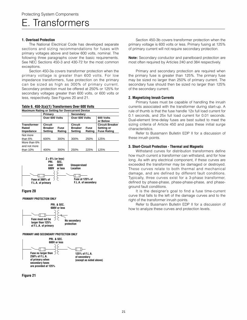
Section 450-3a covers transformer protection when theprimary voltage is greater than 600 volts. For lowimpedance transformers, fuse protection on the primarycan be sized as high as 300% of primary current.Secondary protection must be offered at 250% or 125% forsecondary voltages greater than 600 volts, or 600 volts orless, respectively. See Figures 20 and 21.
Table 6. 450-3(a)(1) Transformers Over 600 VoltsMaximum Rating or Setting for Overcurrent Device
Primary SecondaryOver 600 Volts Over 600 Volts 600 Volts
or BelowTransformer Circuit Circuit Circuit BreakerRated Breaker Fuse Breaker Fuse Setting orImpedance Setting Rating Setting Rating Fuse RatingNot morethan 6% 600% 300% 300% 250% 125%More than 6%and not morethan 10% 400% 300% 250% 225% 125%
Figure 20
Figure 21
Fuse at 300% ofF.L.A. of primary
Fuse at 125% ofF.L.A. of secondary
UnsupervisedLocation
Z = 6% (or less)PRI.over600V
SEC.600Vor less
PRIMARY PROTECTION ONLY
Fuse must not belarger than 125%of F.L.A. of primary
No secondaryprotection
PRI. & SEC.600V or less
PRIMARY AND SECONDARY PROTECTION ONLY
Fuse no larger than 250% of F.L.A.of primary whensecondary fusesare provided at 125%
125% of F.L.A.of secondary(except as noted above)
PRI. & SEC.600V or less
21
Section 450-3b covers transformer protection when theprimary voltage is 600 volts or less. Primary fusing at 125%of primary current will not require secondary protection.
Note: Secondary conductor and panelboard protection aremost often required by Articles 240 and 384 respectively.
Primary and secondary protection are required whenthe primary fuse is greater than 125%. The primary fusemay be sized no larger than 250% of primary current. Thesecondary fuse should then be sized no larger than 125%of the secondary current.
2. Magnetizing Inrush CurrentsPrimary fuses must be capable of handling the inrush
currents associated with the transformer during start-up. Arule of thumb is that the fuse handle 12x full load current for0.1 seconds, and 25x full load current for 0.01 seconds.Dual-element time-delay fuses are best suited to meet thesizing criteria of Article 450 and pass these initial surgecharacteristics.
Refer to Bussmann Bulletin EDP II for a discussion ofthese inrush points.
3. Short-Circuit Protection - Thermal and MagneticWithstand curves for distribution transformers define
how much current a transformer can withstand, and for howlong. As with any electrical component, if these curves areexceeded the transformer may be damaged or destroyed.These curves relate to both thermal and mechanicaldamage, and are defined by different fault conditions.Typically, three curves exist for a 3-phase transformer,defined by phase-phase, phase-phase-phase, and phase-ground fault conditions.
It is the designer’s goal to find a fuse time-currentcurve that falls to the left of the damage curves and to theright of the transformer inrush points.
Refer to Bussmann Bulletin EDP II for a discussion ofhow to analyze these curves and protection levels.
Protecting System Components
F. Ballasts
The National Electrical Code requires integral thermalprotection for ballasts in Section 410-73(e).
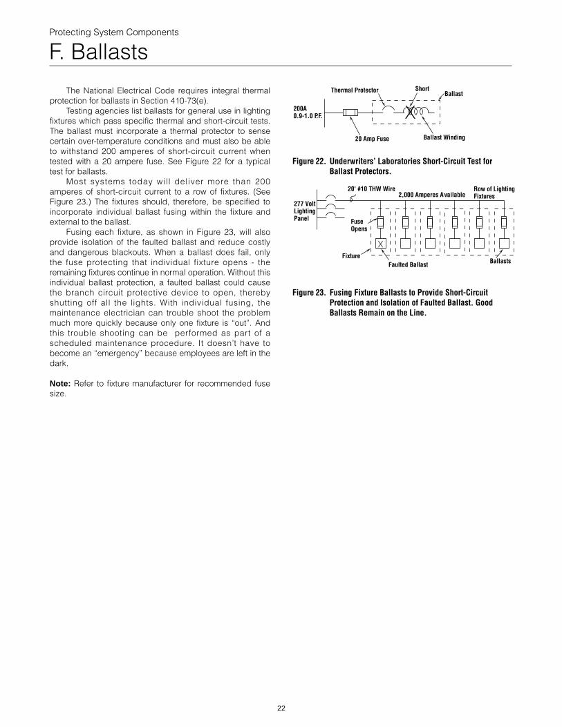
Testing agencies list ballasts for general use in lightingfixtures which pass specific thermal and short-circuit tests.The ballast must incorporate a thermal protector to sensecertain over-temperature conditions and must also be ableto withstand 200 amperes of short-circuit current whentested with a 20 ampere fuse. See Figure 22 for a typicaltest for ballasts.
Most systems today wil l deliver more than 200amperes of short-circuit current to a row of fixtures. (SeeFigure 23.) The fixtures should, therefore, be specified toincorporate individual ballast fusing within the fixture andexternal to the ballast.
Fusing each fixture, as shown in Figure 23, will alsoprovide isolation of the faulted ballast and reduce costlyand dangerous blackouts. When a ballast does fail, onlythe fuse protecting that individual fixture opens - theremaining fixtures continue in normal operation. Without thisindividual ballast protection, a faulted ballast could causethe branch circuit protective device to open, therebyshutting off all the lights. With individual fusing, themaintenance electrician can trouble shoot the problemmuch more quickly because only one fixture is “out”. Andthis trouble shooting can be performed as part of ascheduled maintenance procedure. It doesn’t have tobecome an “emergency” because employees are left in thedark.
Note: Refer to fixture manufacturer for recommended fusesize.
22
Figure 22. Underwriters’ Laboratories Short-Circuit Test forBallast Protectors.
Figure 23. Fusing Fixture Ballasts to Provide Short-CircuitProtection and Isolation of Faulted Ballast. GoodBallasts Remain on the Line.
Thermal Protector ShortBallast
Ballast Winding20 Amp Fuse
200A0.9-1.0 P.F.
20' #10 THW Wire2,000 Amperes Available
Row of LightingFixtures
FuseOpens
FixtureFaulted Ballast Ballasts
277 VoltLightingPanel
Protecting System Components
G. Transfer Switches
Transfer switches are designed to transfer powersources under load in order to feed a system, typically anemergency system, on critical loads. These devices aretested to meet basic short-circuit testing requirements.Transfer switches are often tested per U.L. Standard 1008.
Transfer switches should always be evaluated on thebasis of the maximum available short-circuit currents. Theautomatic transfer switch must withstand: a) the magneticstresses imposed by the instantaneous peak currentavailable at the point of application, and b) the thermalstresses imposed by the available RMS short-circuitcurrent. The short-circuit current withstand rating of thetransfer switch must be equal to or greater than theavailable short-circuit current at the point of application.
When properly coordinated with current-limitingdevices, automatic transfer switches can be used oncircuits having available short-circuit currents greater thantheir unprotected withstand short-circuit current rating.Modern current-limiting fuses, when properly sized, limit theshort-circuit current to within the withstand rating of atransfer switch.
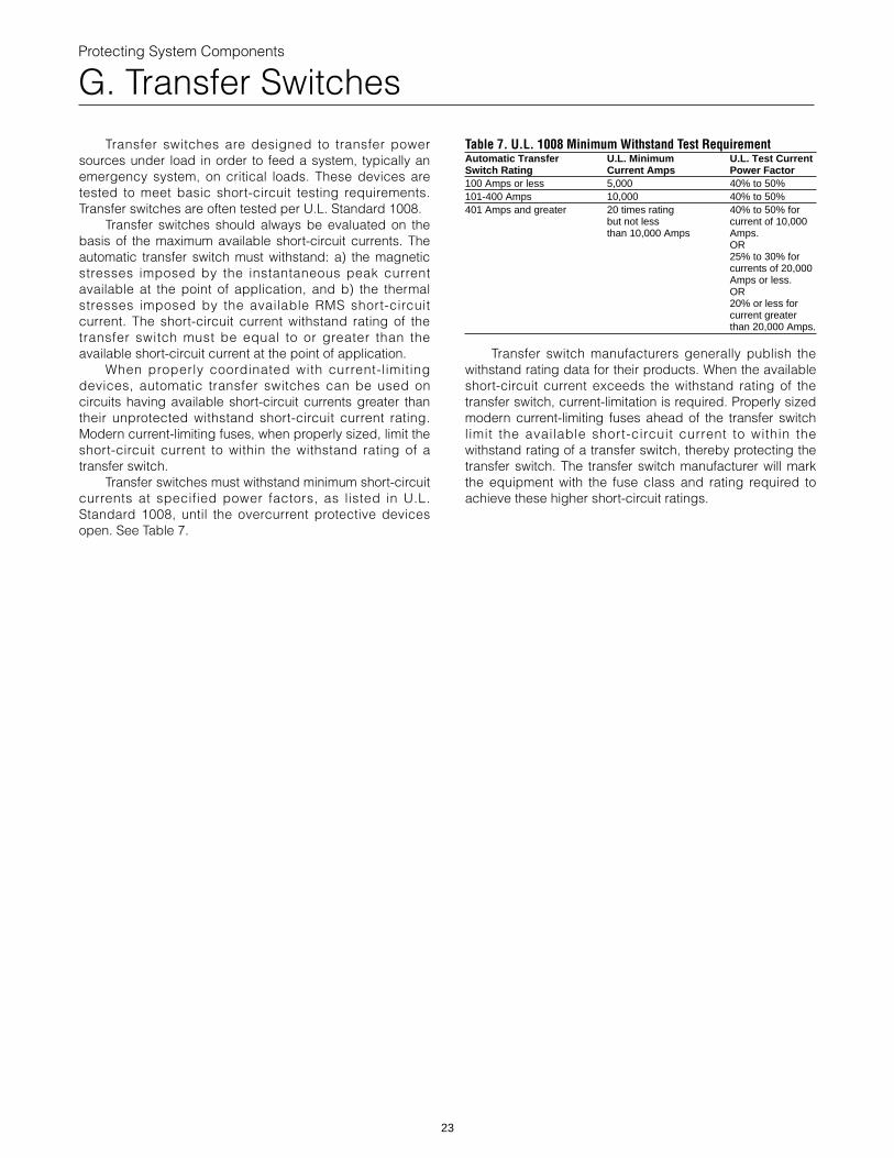
Transfer switches must withstand minimum short-circuitcurrents at specified power factors, as listed in U.L.Standard 1008, until the overcurrent protective devicesopen. See Table 7.
23
Table 7. U.L. 1008 Minimum Withstand Test RequirementAutomatic Transfer U.L. Minimum U.L. Test CurrentSwitch Rating Current Amps Power Factor100 Amps or less 5,000 40% to 50%101-400 Amps 10,000 40% to 50%401 Amps and greater 20 times rating 40% to 50% for
but not less current of 10,000than 10,000 Amps Amps.
OR25% to 30% forcurrents of 20,000Amps or less.OR20% or less forcurrent greaterthan 20,000 Amps.
Transfer switch manufacturers generally publish thewithstand rating data for their products. When the availableshort-circuit current exceeds the withstand rating of thetransfer switch, current-limitation is required. Properly sizedmodern current-limiting fuses ahead of the transfer switchlimit the available short-circuit current to within thewithstand rating of a transfer switch, thereby protecting thetransfer switch. The transfer switch manufacturer will markthe equipment with the fuse class and rating required toachieve these higher short-circuit ratings.
Protecting System Components
H. HVAC Equipment
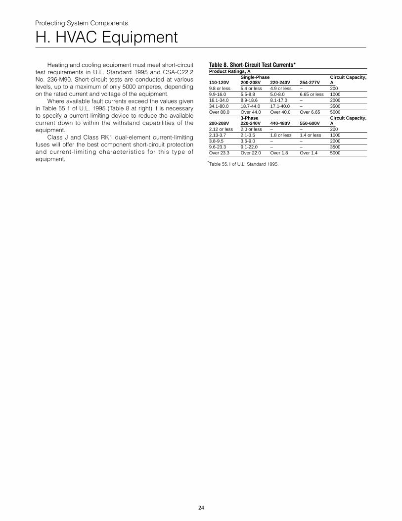
Heating and cooling equipment must meet short-circuittest requirements in U.L. Standard 1995 and CSA-C22.2No. 236-M90. Short-circuit tests are conducted at variouslevels, up to a maximum of only 5000 amperes, dependingon the rated current and voltage of the equipment.
Where available fault currents exceed the values givenin Table 55.1 of U.L. 1995 (Table 8 at right) it is necessaryto specify a current limiting device to reduce the availablecurrent down to within the withstand capabilities of theequipment.
Class J and Class RK1 dual-element current-limitingfuses will offer the best component short-circuit protectionand current-l imiting characteristics for this type ofequipment.
24
Table 8. Short-Circuit Test Currents*Product Ratings, A
Single-Phase Circuit Capacity,110-120V 200-208V 220-240V 254-277V A9.8 or less 5.4 or less 4.9 or less – 2009.9-16.0 5.5-8.8 5.0-8.0 6.65 or less 100016.1-34.0 8.9-18.6 8.1-17.0 – 200034.1-80.0 18.7-44.0 17.1-40.0 – 3500Over 80.0 Over 44.0 Over 40.0 Over 6.65 5000
3-Phase Circuit Capacity,200-208V 220-240V 440-480V 550-600V A2.12 or less 2.0 or less – – 2002.13-3.7 2.1-3.5 1.8 or less 1.4 or less 10003.8-9.5 3.6-9.0 – – 20009.6-23.3 9.1-22.0 – – 3500Over 23.3 Over 22.0 Over 1.8 Over 1.4 5000
Table 55.1 of U.L. Standard 1995.*
Buss® Fuse Current- Limiting Let-Thru Charts
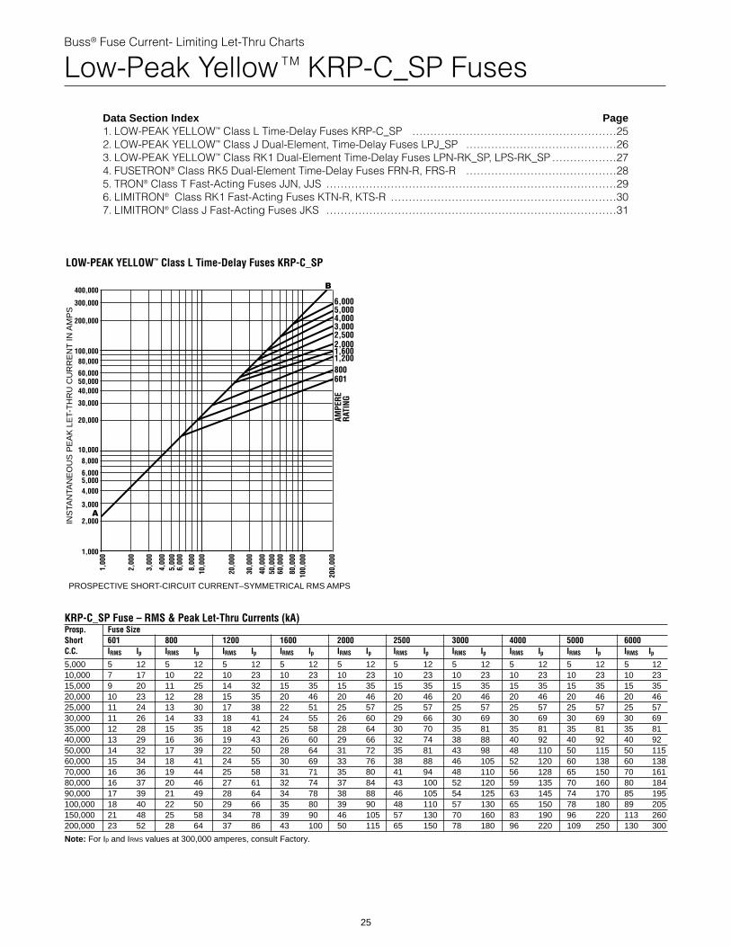
Low-Peak Yellow TM KRP-C_SP Fuses
Data Section Index Page1. LOW-PEAK YELLOW™ Class L Time-Delay Fuses KRP-C_SP …………………………………………………252. LOW-PEAK YELLOW™ Class J Dual-Element, Time-Delay Fuses LPJ_SP ……………………………………263. LOW-PEAK YELLOW™ Class RK1 Dual-Element Time-Delay Fuses LPN-RK_SP, LPS-RK_SP ………………274. FUSETRON® Class RK5 Dual-Element Time-Delay Fuses FRN-R, FRS-R ……………………………………285. TRON® Class T Fast-Acting Fuses JJN, JJS ………………………………………………………………………296. LIMITRON® Class RK1 Fast-Acting Fuses KTN-R, KTS-R ………………………………………………………307. LIMITRON® Class J Fast-Acting Fuses JKS ………………………………………………………………………31
400,000
300,000
200,000
100,00080,000
60,000
40,000
30,000
20,000
10,0008,000
6,000
4,000
3,000
2,000
1,000
5,000
50,000
1,00
0
2,00
0
3,00
0
4,00
05,
000
6,00
0
8,00
010
,000
20,0
00
30,0
00
40,0
0050
,000
60,0
00
80,0
0010
0,00
0
200,
000
6,0005,0004,0003,0002,5002,0001,6001,200800601
AMPE
RERA
TING
INS
TAN
TAN
EO
US
PE
AK
LE
T-T
HR
U C
UR
RE
NT
IN A
MP
S
PROSPECTIVE SHORT-CIRCUIT CURRENT–SYMMETRICAL RMS AMPS
A
B
LOW-PEAK YELLOW™ Class L Time-Delay Fuses KRP-C_SP
KRP-C_SP Fuse – RMS & Peak Let-Thru Currents (kA)Prosp. Fuse SizeShort 601 800 1200 1600 2000 2500C.C. IRMS Ip IRMS Ip IRMS Ip IRMS Ip IRMS Ip IRMS Ip5,000 5 12 5 12 5 12 5 12 5 12 5 1210,000 7 17 10 22 10 23 10 23 10 23 10 2315,000 9 20 11 25 14 32 15 35 15 35 15 3520,000 10 23 12 28 15 35 20 46 20 46 20 4625,000 11 24 13 30 17 38 22 51 25 57 25 5730,000 11 26 14 33 18 41 24 55 26 60 29 6635,000 12 28 15 35 18 42 25 58 28 64 30 7040,000 13 29 16 36 19 43 26 60 29 66 32 7450,000 14 32 17 39 22 50 28 64 31 72 35 8160,000 15 34 18 41 24 55 30 69 33 76 38 8870,000 16 36 19 44 25 58 31 71 35 80 41 9480,000 16 37 20 46 27 61 32 74 37 84 43 10090,000 17 39 21 49 28 64 34 78 38 88 46 105100,000 18 40 22 50 29 66 35 80 39 90 48 110150,000 21 48 25 58 34 78 39 90 46 105 57 130200,000 23 52 28 64 37 86 43 100 50 115 65 150
Note: For Ip and IRMS values at 300,000 amperes, consult Factory.
25
3000 4000 5000 6000IRMS Ip IRMS Ip IRMS Ip IRMS Ip5 12 5 12 5 12 5 1210 23 10 23 10 23 10 2315 35 15 35 15 35 15 3520 46 20 46 20 46 20 4625 57 25 57 25 57 25 5730 69 30 69 30 69 30 6935 81 35 81 35 81 35 8138 88 40 92 40 92 40 9243 98 48 110 50 115 50 11546 105 52 120 60 138 60 13848 110 56 128 65 150 70 16152 120 59 135 70 160 80 18454 125 63 145 74 170 85 19557 130 65 150 78 180 89 20570 160 83 190 96 220 113 26078 180 96 220 109 250 130 300
Buss® Fuse Current- Limiting Let-Thru Charts
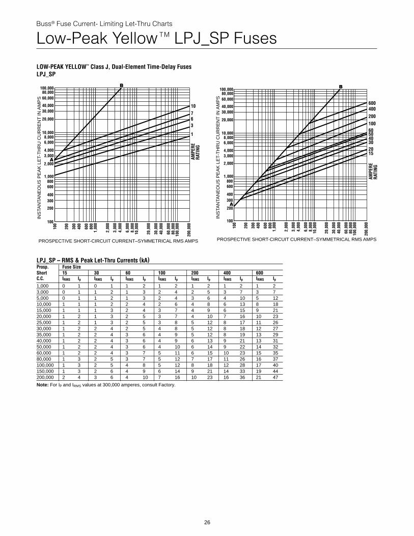
Low-Peak Yellow TM LPJ_SP Fuses
LOW-PEAK YELLOW™ Class J, Dual-Element Time-Delay FusesLPJ_SP
INS
TAN
TAN
EO
US
PE
AK
LE
T-T
HR
U C
UR
RE
NT
IN A
MP
S
PROSPECTIVE SHORT-CIRCUIT CURRENT–SYMMETRICAL RMS AMPS
100,00080,00060,000
40,00030,000
20,000
10,0008,0006,000
4,0003,000
2,000
1,000800600
400300
200
100
100
200
300
400
600
800
1,00
0
2,00
0
3,00
04,
000
6,00
08,
000
10,0
00
20,0
00
30,0
0040
,000
60,0
0080
,000
100,
000
200,
000
107
36
1
AMPE
RERA
TING
A
B
26
INS
TAN
TAN
EO
US
PE
AK
LE
T-T
HR
U C
UR
RE
NT
IN A
MP
S
PROSPECTIVE SHORT-CIRCUIT CURRENT–SYMMETRICAL RMS AMPS
100,00080,00060,000
40,00030,000
20,000
10,0008,0006,000
4,0003,000
2,000
1,000800600
400300
200
100
100
200
300
400
600
800
1,00
0
2,00
0
3,00
04,
000
6,00
08,
000
10,0
00
20,0
00
30,0
0040
,000
60,0
0080
,000
100,
000
200,
000
600400
200100605040302015
AMPE
RERA
TING
B
A
LPJ_SP – RMS & Peak Let-Thru Currents (kA)Prosp. Fuse SizeShort 15 30 60 100 200 400 600C.C. IRMS Ip IRMS Ip IRMS Ip IRMS Ip IRMS Ip IRMS Ip IRMS Ip1,000 0 1 0 1 1 2 1 2 1 2 1 2 1 23,000 0 1 1 2 1 3 2 4 2 5 3 7 3 75,000 0 1 1 2 1 3 2 4 3 6 4 10 5 1210,000 1 1 1 2 2 4 2 6 4 8 6 13 8 1815,000 1 1 1 3 2 4 3 7 4 9 6 15 9 2120,000 1 2 1 3 2 5 3 7 4 10 7 16 10 2325,000 1 2 1 3 2 5 3 8 5 12 8 17 11 2630,000 1 2 2 4 2 5 4 8 5 12 8 18 12 2735,000 1 2 2 4 3 6 4 9 5 12 8 19 13 2940,000 1 2 2 4 3 6 4 9 6 13 9 21 13 3150,000 1 2 2 4 3 6 4 10 6 14 9 22 14 3260,000 1 2 2 4 3 7 5 11 6 15 10 23 15 3580,000 1 3 2 5 3 7 5 12 7 17 11 26 16 37100,000 1 3 2 5 4 8 5 12 8 18 12 28 17 40150,000 1 3 2 6 4 9 6 14 9 21 14 33 19 44200,000 2 4 3 6 4 10 7 16 10 23 16 36 21 47
Note: For Ip and IRMS values at 300,000 amperes, consult Factory.
Buss® Fuse Current- Limiting Let-Thru Charts
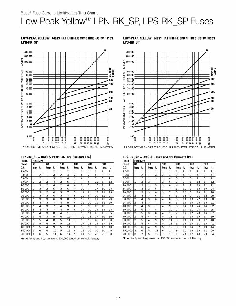
Low-Peak YellowTM LPN-RK_SP, LPS-RK_SP Fuses
LOW-PEAK YELLOW™ Class RK1 Dual-Element Time-Delay Fuses LPN-RK_SP
INS
TAN
TAN
EO
US
PE
AK
LE
T-T
HR
U C
UR
RE
NT
IN A
MP
S
PROSPECTIVE SHORT-CIRCUIT CURRENT–SYMMETRICAL RMS AMPS
400,000
300,000
200,000
100,00080,000
60,000
40,000
30,000
20,000
10,0008,000
6,000
4,000
3,000
2,000
1,000
5,000
50,000
1,00
0
2,00
0
3,00
0
4,00
05,
000
6,00
0
8,00
010
,000
20,0
00
30,0
00
40,0
0050
,000
60,0
00
80,0
0010
0,00
0
200,
000
600400
200
10060
30AM
PERE
RATI
NG
A
B
LPN-RK_SP – RMS & Peak Let-Thru Currents (kA)Prosp. Fuse SizeShort 30 60 100 200 400 600C.C. IRMS Ip IRMS Ip IRMS Ip IRMS Ip IRMS Ip IRMS Ip1,000 1 1 1 2 1 2 1 2 1 2 1 22,000 1 2 1 3 2 4 2 5 2 5 2 53,000 1 2 1 3 2 4 3 6 3 7 3 75,000 1 2 2 4 2 5 3 7 5 12 5 1210,000 1 3 2 4 2 6 4 9 7 15 9 2115,000 1 3 2 5 3 6 4 10 7 17 10 2320,000 1 3 2 6 3 7 5 11 8 19 11 2525,000 1 3 3 6 3 7 5 12 9 20 12 2730,000 2 3 3 6 3 8 5 12 9 21 13 2935,000 2 4 3 7 4 8 6 13 10 22 13 3040,000 2 4 3 7 4 9 6 13 10 23 13 3150,000 2 4 3 7 4 9 6 14 10 24 14 3360,000 2 4 3 8 4 10 7 15 11 26 15 3570,000 2 4 3 8 4 10 7 16 12 27 16 3680,000 2 5 4 8 5 11 7 16 12 28 17 3890,000 2 5 4 9 5 11 7 17 13 29 17 39100,000 2 5 4 9 5 11 8 18 13 30 17 40150,000 2 6 4 10 5 13 8 19 16 36 20 46200,000 3 6 5 11 6 14 9 21 18 42 22 50
Note: For Ip and IRMS values at 300,000 amperes, consult Factory.
27
LOW-PEAK YELLOW™ Class RK1 Dual-Element Time-Delay Fuses LPS-RK_SP
INS
TAN
TAN
EO
US
PE
AK
LE
T-T
HR
U C
UR
RE
NT
IN A
MP
S
PROSPECTIVE SHORT CIRCUIT-CURRENT–SYMMETRICAL RMS AMPS
400,000
300,000
200,000
100,00080,000
60,000
40,000
30,000
20,000
10,0008,000
6,000
4,000
3,000
2,000
1,000
5,000
50,000
1,00
0
2,00
0
3,00
0
4,00
05,
000
6,00
0
8,00
010
,000
20,0
00
30,0
00
40,0
0050
,000
60,0
00
80,0
0010
0,00
0
200,
000
600
400
200
10060
30
AMPE
RERA
TING
A
B
LPS-RK_SP – RMS & Peak Let-Thru Currents (kA)Prosp. Fuse SizeShort 30 60 100 200 400 600C.C. IRMS Ip IRMS Ip IRMS Ip IRMS Ip IRMS Ip IRMS Ip1,000 1 1 1 2 1 2 1 2 1 2 1 22,000 1 2 1 3 2 4 2 4 2 4 2 43,000 1 2 1 3 2 4 3 6 3 7 3 75,000 1 2 2 4 2 5 3 7 5 12 5 1210,000 1 3 2 5 3 6 4 9 7 16 9 2115,000 1 3 2 5 3 7 5 11 8 18 10 2420,000 1 3 3 6 3 7 5 12 8 19 11 2625,000 2 4 3 6 3 8 5 12 9 21 12 2830,000 2 4 3 6 4 8 6 13 10 22 13 3035,000 2 4 3 7 4 9 6 14 10 23 13 3140,000 2 4 3 7 4 9 6 14 10 24 14 3250,000 2 5 3 8 4 10 7 15 11 26 15 3560,000 2 5 3 8 4 10 7 16 12 28 16 3770,000 2 5 4 8 5 11 7 17 13 29 17 3980,000 2 5 4 9 5 11 8 18 13 30 17 4090,000 2 5 4 9 5 12 8 18 13 31 18 42100,000 2 6 4 9 5 12 8 19 14 32 19 44150,000 3 6 5 11 6 14 9 21 16 36 22 50200,000 3 7 5 12 7 15 10 23 17 40 23 54
Note: For Ip and IRMS values at 300,000 amperes, consult Factory.
Data Section
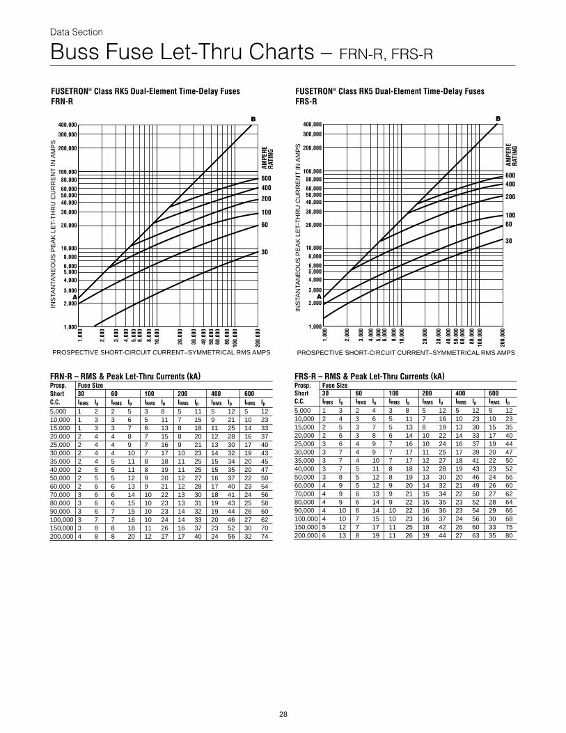
Buss Fuse Let-Thru Charts – FRN-R, FRS-R
FUSETRON® Class RK5 Dual-Element Time-Delay Fuses FRN-R
400,000
300,000
200,000
100,00080,000
60,000
40,000
30,000
20,000
10,0008,000
6,000
4,000
3,000
2,000
1,000
5,000
50,000
1,00
0
2,00
0
3,00
0
4,00
05,
000
6,00
0
8,00
010
,000
20,0
00
30,0
00
40,0
0050
,000
60,0
00
80,0
0010
0,00
0
200,
000
INS
TAN
TAN
EO
US
PE
AK
LE
T-T
HR
U C
UR
RE
NT
IN A
MP
S
PROSPECTIVE SHORT-CIRCUIT CURRENT–SYMMETRICAL RMS AMPS
A
B
600
100
AMPE
RERA
TING
30
60
400
200
FRN-R – RMS & Peak Let-Thru Currents (kA)Prosp. Fuse SizeShort 30 60 100 200 400 600C.C. IRMS Ip IRMS Ip IRMS Ip IRMS Ip IRMS Ip IRMS Ip5,000 1 2 2 5 3 8 5 11 5 12 5 1210,000 1 3 3 6 5 11 7 15 9 21 10 2315,000 1 3 3 7 6 13 8 18 11 25 14 3320,000 2 4 4 8 7 15 8 20 12 28 16 3725,000 2 4 4 9 7 16 9 21 13 30 17 4030,000 2 4 4 10 7 17 10 23 14 32 19 4335,000 2 4 5 11 8 18 11 25 15 34 20 4540,000 2 5 5 11 8 19 11 25 15 35 20 4750,000 2 5 5 12 9 20 12 27 16 37 22 5060,000 2 6 6 13 9 21 12 28 17 40 23 5470,000 3 6 6 14 10 22 13 30 18 41 24 5680,000 3 6 6 15 10 23 13 31 19 43 25 5890,000 3 6 7 15 10 23 14 32 19 44 26 60100,000 3 7 7 16 10 24 14 33 20 46 27 62150,000 3 8 8 18 11 26 16 37 23 52 30 70200,000 4 8 8 20 12 27 17 40 24 56 32 74
28
FUSETRON® Class RK5 Dual-Element Time-Delay Fuses FRS-R
400,000
300,000
200,000
100,00080,000
60,000
40,000
30,000
20,000
10,0008,000
6,000
4,000
3,000
2,000
1,000
5,000
50,000
1,00
0
2,00
0
3,00
0
4,00
05,
000
6,00
0
8,00
010
,000
20,0
00
30,0
00
40,0
0050
,000
60,0
00
80,0
0010
0,00
0
200,
000
INS
TAN
TAN
EO
US
PE
AK
LE
T-T
HR
U C
UR
RE
NT
IN A
MP
S
PROSPECTIVE SHORT-CIRCUIT CURRENT–SYMMETRICAL RMS AMPS
B
A
600
100
30
AMPE
RERA
TING
60
400
200
FRS-R – RMS & Peak Let-Thru Currents (kA)Prosp. Fuse SizeShort 30 60 100 200 400 600C.C. IRMS Ip IRMS Ip IRMS Ip IRMS Ip IRMS Ip IRMS Ip5,000 1 3 2 4 3 8 5 12 5 12 5 1210,000 2 4 3 6 5 11 7 16 10 23 10 2315,000 2 5 3 7 5 13 8 19 13 30 15 3520,000 2 6 3 8 6 14 10 22 14 33 17 4025,000 3 6 4 9 7 16 10 24 16 37 19 4430,000 3 7 4 9 7 17 11 25 17 39 20 4735,000 3 7 4 10 7 17 12 27 18 41 22 5040,000 3 7 5 11 8 18 12 28 19 43 23 5250,000 3 8 5 12 8 19 13 30 20 46 24 5660,000 4 9 5 12 9 20 14 32 21 49 26 6070,000 4 9 6 13 9 21 15 34 22 50 27 6280,000 4 9 6 14 9 22 15 35 23 52 28 6490,000 4 10 6 14 10 22 16 36 23 54 29 66100,000 4 10 7 15 10 23 16 37 24 56 30 68150,000 5 12 7 17 11 25 18 42 26 60 33 75200,000 6 13 8 19 11 26 19 44 27 63 35 80
Data Section
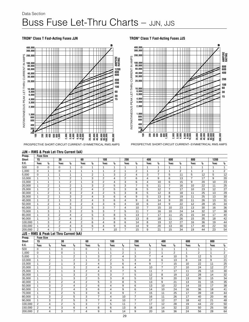
Buss Fuse Let-Thru Charts – JJN, JJS
TRON® Class T Fast-Acting Fuses JJN
INS
TAN
TAN
EO
US
PE
AK
LE
T-T
HR
U C
UR
RE
NT
IN A
MP
S
PROSPECTIVE SHORT-CIRCUIT CURRENT–SYMMETRICAL RMS AMPS
100,00080,00060,000
40,00030,000
20,000
10,0008,0006,000
4,0003,000
2,000
1,000800600
400300
200
100
200
300
400
600
800
1,00
0
2,00
0
3,00
04,
000
6,00
08,
000
10,0
00
20,0
00
30,0
0040
,000
60,0
0080
,000
100,
000
200,
000
200,000
400,000300,000
600
400200100
603015
AMPE
RERA
TING
8001200
B
A
TRON® Class T Fast-Acting Fuses JJS
INS
TAN
TAN
EO
US
PE
AK
LE
T-T
HR
U C
UR
RE
NT
IN A
MP
S
PROSPECTIVE SHORT-CIRCUIT CURRENT–SYMMETRICAL RMS AMPS
100,00080,00060,000
40,00030,000
20,000
10,0008,0006,000
4,0003,000
2,000
1,000800600
400300
200
100
200
300
400
600
800
1,00
0
2,00
0
3,00
04,
000
6,00
08,
000
10,0
00
20,0
00
30,0
0040
,000
60,0
0080
,000
100,
000
200,
000
200,000
400,000300,000
B
A
400
200
1006030
15
AMPE
RERA
TING
600800
JJN – RMS & Peak Let-Thru Current (kA)Prosp. Fuse SizeShort 15 30 60 100 200C.C. IRMS Ip IRMS Ip IRMS Ip IRMS Ip IRMS
500 0 0 0 1 0 1 1 1 11,000 0 1 0 1 1 1 1 2 15,000 0 1 1 1 1 2 1 3 210,000 1 1 1 2 1 3 2 4 215,000 1 1 1 2 1 3 2 4 320,000 1 2 1 2 1 3 2 5 325,000 1 2 1 2 2 4 2 5 330,000 1 2 1 3 2 4 2 5 335,000 1 2 1 3 2 4 3 6 440,000 1 2 1 3 2 4 3 6 450,000 1 2 1 3 2 4 3 6 460,000 1 2 1 3 2 5 3 7 470,000 1 3 1 3 2 5 3 7 580,000 1 3 2 4 2 5 3 8 590,000 1 3 2 4 2 5 3 8 6100,000 1 3 2 4 2 6 4 8 6150,000 1 3 2 4 3 6 4 9 6200,000 2 4 2 5 3 7 4 10 7
JJS – RMS & Peak Let Thru Current (kA)Prosp. Fuse SizeShort 15 30 60 100C.C. IRMS Ip IRMS Ip IRMS Ip IRMS Ip500 0 1 0 1 0 1 1 11,000 0 1 0 1 1 1 1 25,000 1 1 1 2 1 3 2 410,000 1 2 1 2 1 3 2 515,000 1 2 1 3 2 4 3 620,000 1 2 1 3 2 4 3 625,000 1 2 1 3 2 4 3 730,000 1 2 1 3 2 5 3 735,000 1 2 1 3 2 5 3 840,000 1 3 2 4 2 5 3 850,000 1 3 2 4 2 6 4 960,000 1 3 2 4 3 6 4 970,000 1 3 2 5 3 6 4 980,000 1 3 2 5 3 7 4 1090,000 1 3 2 5 3 7 4 10100,000 2 4 2 5 3 7 5 11150,000 2 4 3 6 4 8 6 13200,000 2 4 3 7 4 9 6 14
29
400 600 800 1200Ip IRMS Ip IRMS Ip IRMS Ip IRMS Ip1 1 1 1 1 1 1 1 12 1 2 1 2 1 2 1 24 3 7 5 11 5 12 5 126 4 9 6 13 7 17 9 206 4 10 6 15 9 20 10 237 5 11 7 16 10 22 11 258 5 12 7 17 10 23 12 278 5 12 8 18 11 25 13 299 5 13 8 19 11 25 13 309 6 14 9 20 11 26 13 3110 6 14 9 22 12 28 15 3410 7 15 10 23 13 30 16 3611 7 16 10 24 14 32 17 3813 7 17 11 25 15 34 17 4013 8 18 11 26 15 35 18 4214 8 19 12 27 16 36 19 4414 9 20 13 30 17 40 22 5015 9 21 15 34 19 44 23 54
200 400 600 800IRMS Ip IRMS Ip IRMS Ip IRMS Ip1 1 1 1 1 1 1 11 2 1 2 1 2 1 23 7 4 10 5 12 5 123 8 6 13 8 19 9 214 9 7 15 10 22 11 254 10 7 17 10 24 12 275 11 7 17 11 26 13 305 12 8 19 12 28 14 325 12 9 20 13 30 15 345 13 9 21 13 31 15 356 13 10 22 14 33 17 386 14 10 24 16 36 18 417 15 11 25 17 39 19 447 16 11 26 17 40 20 467 17 12 27 18 42 21 487 17 12 28 19 44 22 508 18 14 32 22 50 25 589 20 16 36 24 56 28 64
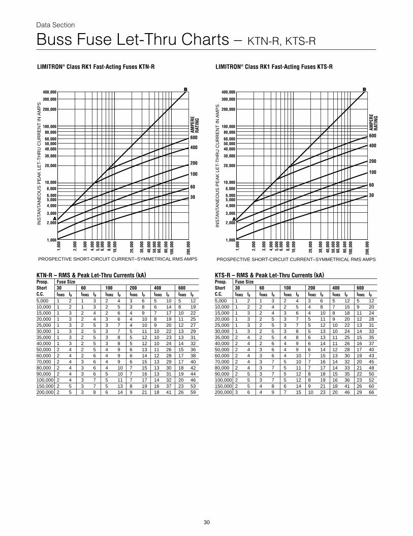
Data Section
Buss Fuse Let-Thru Charts – KTN-R, KTS-R
LIMITRON® Class RK1 Fast-Acting Fuses KTN-R
400,000
300,000
200,000
100,00080,000
60,000
40,000
30,000
20,000
10,0008,000
6,000
4,000
3,000
2,000
1,000
5,000
50,000
1,00
0
2,00
0
3,00
0
4,00
05,
000
6,00
0
8,00
010
,000
20,0
00
30,0
00
40,0
0050
,000
60,0
00
80,0
0010
0,00
0
200,
000
INS
TAN
TAN
EO
US
PE
AK
LE
T-T
HR
U C
UR
RE
NT
IN A
MP
S
PROSPECTIVE SHORT-CIRCUIT CURRENT–SYMMETRICAL RMS AMPS
B
A
600
100
60AM
PERE
RATI
NG30
400
200
KTN-R – RMS & Peak Let-Thru Currents (kA)Prosp. Fuse SizeShort 30 60 100 200 400 600C.C. IRMS Ip IRMS Ip IRMS Ip IRMS Ip IRMS Ip IRMS Ip5,000 1 2 1 3 2 4 3 6 5 10 5 1210,000 1 2 1 3 2 5 3 8 6 14 8 1915,000 1 3 2 4 2 6 4 9 7 17 10 2220,000 1 3 2 4 3 6 4 10 8 19 11 2525,000 1 3 2 5 3 7 4 10 9 20 12 2730,000 1 3 2 5 3 7 5 11 10 22 13 2935,000 1 3 2 5 3 8 5 12 10 23 13 3140,000 1 3 2 5 3 8 5 12 10 24 14 3250,000 2 4 2 5 4 9 6 13 11 26 15 3660,000 2 4 2 6 4 9 6 14 12 28 17 3870,000 2 4 3 6 4 9 6 15 13 29 17 4080,000 2 4 3 6 4 10 7 15 13 30 18 4290,000 2 4 3 6 5 10 7 16 13 31 19 44100,000 2 4 3 7 5 11 7 17 14 32 20 46150,000 2 5 3 7 5 13 8 19 16 37 23 53200,000 2 5 3 8 6 14 9 21 18 41 26 59
30
LIMITRON® Class RK1 Fast-Acting Fuses KTS-R
400,000
300,000
200,000
100,00080,000
60,000
40,000
30,000
20,000
10,0008,000
6,000
4,000
3,000
2,000
1,000
5,000
50,000
1,00
0
2,00
0
3,00
0
4,00
05,
000
6,00
0
8,00
010
,000
20,0
00
30,0
00
40,0
0050
,000
60,0
00
80,0
0010
0,00
0
200,
000
INS
TAN
TAN
EO
US
PE
AK
LE
T-T
HR
U C
UR
RE
NT
IN A
MP
S
PROSPECTIVE SHORT-CIRCUIT CURRENT–SYMMETRICAL RMS AMPS
600
100
60
AMPE
RERA
TING
30
400
200
B
A
KTS-R – RMS & Peak Let-Thru Currents (kA)Prosp. Fuse SizeShort 30 60 100 200 400 600C.C. IRMS Ip IRMS Ip IRMS Ip IRMS Ip IRMS Ip IRMS Ip5,000 1 2 1 3 2 4 3 6 5 12 5 1210,000 1 2 2 4 2 5 4 8 7 15 9 2015,000 1 3 2 4 3 6 4 10 8 18 11 2420,000 1 3 2 5 3 7 5 11 9 20 12 2825,000 1 3 2 5 3 7 5 12 10 22 13 3130,000 1 3 2 5 3 8 5 13 10 24 14 3335,000 2 4 2 5 4 8 6 13 11 25 15 3540,000 2 4 2 6 4 9 6 14 11 26 16 3750,000 2 4 3 6 4 9 6 14 12 28 17 4060,000 2 4 3 6 4 10 7 15 13 30 19 4370,000 2 4 3 7 5 10 7 16 14 32 20 4580,000 2 4 3 7 5 11 7 17 14 33 21 4890,000 2 5 3 7 5 12 8 18 15 35 22 50100,000 2 5 3 7 5 12 8 19 16 36 23 52150,000 2 5 4 8 6 14 9 21 18 41 26 60200,000 3 6 4 9 7 15 10 23 20 46 29 66
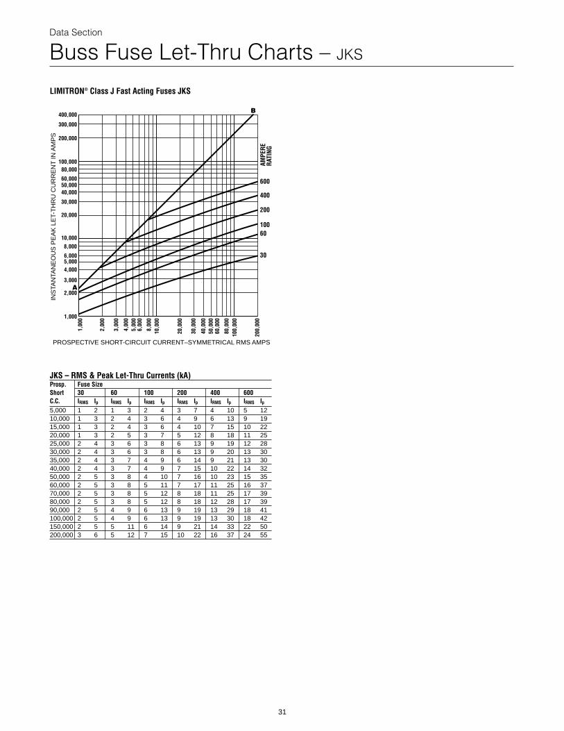
Data Section
Buss Fuse Let-Thru Charts – JKS
LIMITRON® Class J Fast Acting Fuses JKS
400,000
300,000
200,000
100,00080,000
60,000
40,000
30,000
20,000
10,0008,000
6,000
4,000
3,000
2,000
1,000
5,000
50,000
1,00
0
2,00
0
3,00
0
4,00
05,
000
6,00
0
8,00
010
,000
20,0
00
30,0
00
40,0
0050
,000
60,0
00
80,0
0010
0,00
0
200,
000
INS
TAN
TAN
EO
US
PE
AK
LE
T-T
HR
U C
UR
RE
NT
IN A
MP
S
PROSPECTIVE SHORT-CIRCUIT CURRENT–SYMMETRICAL RMS AMPS
B
A
600
400
200
AMPE
RERA
TING
10060
30
JKS – RMS & Peak Let-Thru Currents (kA)Prosp. Fuse SizeShort 30 60 100 200 400 600C.C. IRMS Ip IRMS Ip IRMS Ip IRMS Ip IRMS Ip IRMS Ip5,000 1 2 1 3 2 4 3 7 4 10 5 1210,000 1 3 2 4 3 6 4 9 6 13 9 1915,000 1 3 2 4 3 6 4 10 7 15 10 2220,000 1 3 2 5 3 7 5 12 8 18 11 2525,000 2 4 3 6 3 8 6 13 9 19 12 2830,000 2 4 3 6 3 8 6 13 9 20 13 3035,000 2 4 3 7 4 9 6 14 9 21 13 3040,000 2 4 3 7 4 9 7 15 10 22 14 3250,000 2 5 3 8 4 10 7 16 10 23 15 3560,000 2 5 3 8 5 11 7 17 11 25 16 3770,000 2 5 3 8 5 12 8 18 11 25 17 3980,000 2 5 3 8 5 12 8 18 12 28 17 3990,000 2 5 4 9 6 13 9 19 13 29 18 41100,000 2 5 4 9 6 13 9 19 13 30 18 42150,000 2 5 5 11 6 14 9 21 14 33 22 50200,000 3 6 5 12 7 15 10 22 16 37 24 55
31
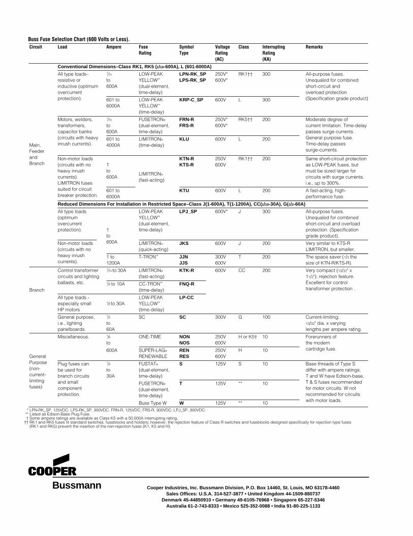
Buss Fuse Selection Chart (600 Volts or Less).Circuit Load Ampere Fuse Symbol Voltage
Rating Type Rating (AC)
Conventional Dimensions–Class RK1, RK5 (1/10-600A), L (601-6000A)
All type loads– 1/10 LOW-PEAK LPN-RK_SP 250V*resistive or to YELLOW™ LPS-RK_SP 600V*inductive (optimum 600A (dual-element,overcurrent time-delay)protection). 601 to LOW-PEAK KRP-C_SP 600V
6000A YELLOW™
(time-delay)
Motors, welders, 1/10 FUSETRON® FRN-R 250V*transformers, to (dual-element, FRS-R 600V*capacitor banks 600A time-delay)(circuits with heavy 601 to LIMITRON® KLU 600V
Main, inrush currents). 4000A (time-delay)Feeder
Class Interrupting RemarksRating(KA)
RK1†† 300 All-purpose fuses.Unequaled for combinedshort-circuit and overload protection.
L 300 (Specification grade product)
RK5†† 200 Moderate degree ofcurrent limitation. Time-delaypasses surge currents.
L 200 General purpose fuse. Time-delay passes surge-currents.
and Non-motor loads KTN-R 250VBranch (circuits with no 1 KTS-R 600V
heavy inrush toLIMITRON®
currents). 600A(fast-acting)
LIMITRON fusessuited for circuit 601 to KTU 600Vbreaker protection. 6000A
Reduced Dimensions For Installation in Restricted Space–Class J(1-600A), T(1-1
All type loads LOW-PEAK LPJ_SP 600V*(optimum YELLOW™
overcurrent (dual-element,protection). 1 time-delay)
to
Non-motor loads 600A LIMITRON® JKS 600V(circuits with no (quick-acting)heavy inrush 1 to T-TRON™ JJN 300Vcurrents). 1200A JJS 600V
RK1†† 200 Same short-circuit protectionas LOW-PEAK fuses, butmust be sized larger forcircuits with surge currents,i.e., up to 300%.
L 200 A fast-acting, high-performance fuse.
200A), CC(1/10-30A), G(1/2-60A)
J 300 All-purpose fuses.Unequaled for combinedshort-circuit and overloadprotection. (Specificationgrade product).
J 200 Very similar to KTS-RLIMITRON, but smaller.
T 200 The space saver (1/3 the size of KTN-R/KTS-R).
Control transformer 1/10 to 30A LIMITRON® KTK-R 600V Ccircuits and lighting (fast-acting)ballasts, etc. 1/4 to 10A CC-TRON™ FNQ-R
Branch (time-delay)
All type loads - LOW-PEAK LP-CCespecially small 1/2 to 30A YELLOW™
HP motors (time-delay)
General purpose, 1/2 SC SC 300V Gi.e., lighting topanelboards. 60A
Miscellaneous. 1/8 ONE-TIME NON 250V Hto NOS 600V
600A SUPER-LAG® REN 250V HGeneral RENEWABLE RES 600VPurpose Plug fuses can 1/4 FUSTAT® S 125V S(non- be used for to (dual-element,current- branch circuits 30A time-delay)limiting and small FUSETRON® T 125V *fuses) component (dual-element,
protection. time-delay)
Buss Type W W 125V *
C 200 Very compact (13/32" x 11/2"); rejection feature.Excellent for controltransformer protection .
100 Current-limiting;13/32" dia. x varyinglengths per ampere rating.
or K5† 10 Forerunners ofthe modern
10 cartridge fuse.
10 Base threads of Type Sdiffer with ampere ratings. T and W have Edison-base.
* 10 T & S fuses recommended for motor circuits. W notrecommended for circuits
* 10 with motor loads.
Bussmann
* LPN-RK_SP, 125VDC; LPS-RK_SP, 300VDC. FRN-R, 125VDC; FRS-R, 300VDC; LPJ_SP, 300VDC.** Listed as Edison-Base Plug Fuse.† Some ampere ratings are available as Class K5 with a 50,000A interrupting rating.
†† RK1 and RK5 fuses fit standard switches, fuseblocks and holders; however, the rejection feature of Class R switches and fuseblocks designed specifically for rejection type fuses (RK1 and RK5) prevent the insertion of the non-rejection fuses (K1, K5 and H).
Cooper Industries, Inc. Bussmann Division, P.O. Box 14460, St. Louis, MO 63178-4460Sales Offices: U.S.A. 314-527-3877 • United Kingdom 44-1509-880737
Denmark 45-44850910 • Germany 49-6105-76968 • Singapore 65-227-5346Australia 61-2-743-8333 • Mexico 525-352-0088 • India 91-80-225-1133