ELE3015 Lecture 2: Transmission Lines Electrical...
36
ELE3015 Lecture 2: Transmission Lines Electrical Parameters Electrical Parameters Dwight Reid
Transcript of ELE3015 Lecture 2: Transmission Lines Electrical...
ELE3015
Lecture 2: Transmission Lines
Electrical ParametersElectrical Parameters
Dwight Reid
Resistance
• The conductors of transmission lines have
resistance.
• Since transmission lines are generally long the
resistance can be significant.resistance can be significant.
• Resistance determines the power dissipated
by the line as it carries power (I2R losses)
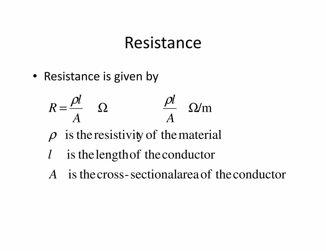
Resistance
• Resistance is given by
/m A
l
A
lR
ρ
ρρΩΩ=
conductor theof area sectional-cross theis
conductor theoflength theis
material theofy resistivit theis
A
l
ρ
Resistance• Commercially available conductors have
standard cross-sectional areas and resistance per unit length (Ω/mile or Ω/km) is normally given in datasheets.
• Resistance also depends on:• Resistance also depends on:
– Temperature
– Frequency (skin effect)
– Current magnitude (for magnetic conductors e.g. iron)
– Conductor Spiralling (due to increase length of individual strands)
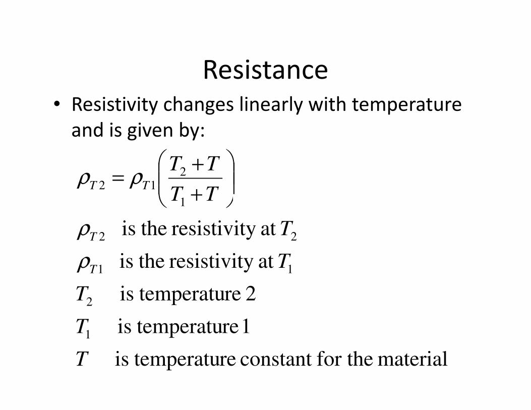
Resistance• Resistivity changes linearly with temperature
and is given by:
1
212
TT
TTTT ρρ
+
+=
material for theconstant re temperatuis
1 re temperatuis
2 re temperatuis
at y resistivit theis
at y resistivit theis
1
2
11
22
1
T
T
T
T
T
TT
T
T
ρ
ρ
+
Resistance• E.g.
Inductance
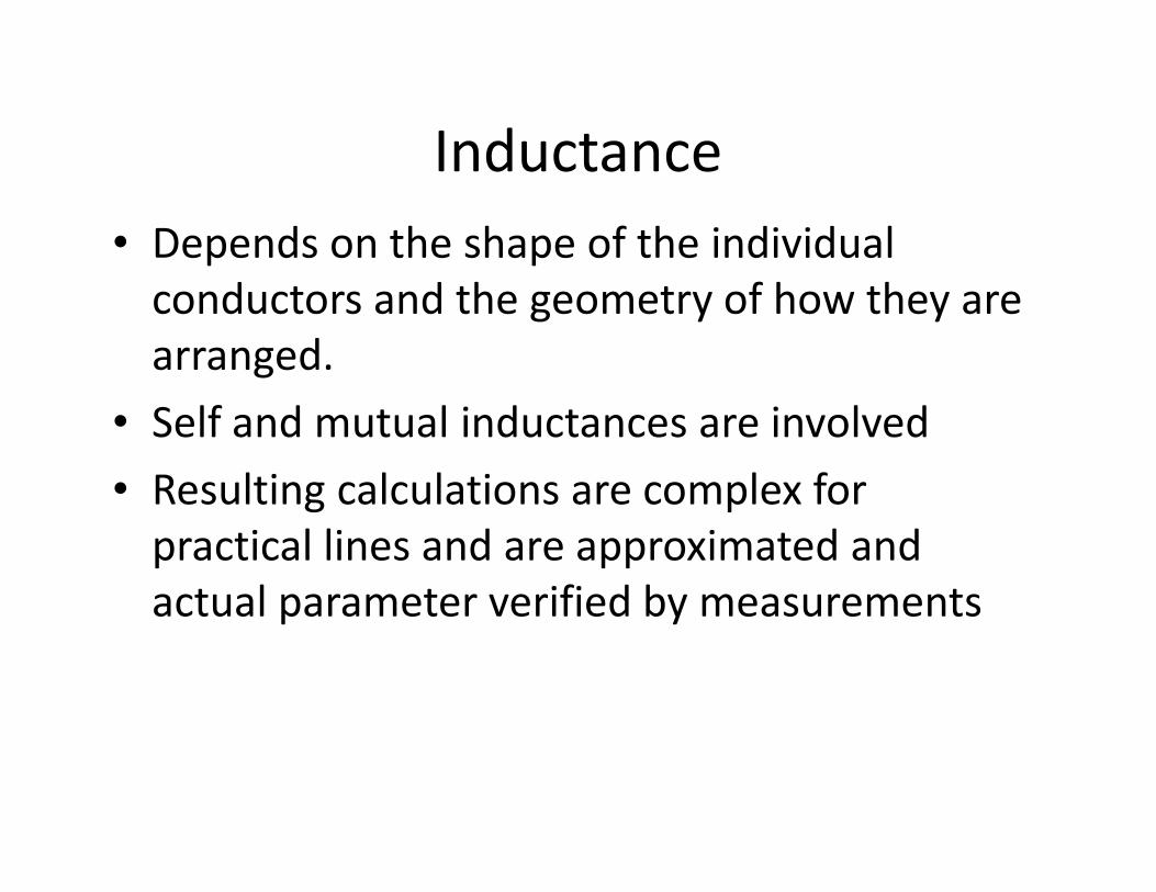
• Depends on the shape of the individual
conductors and the geometry of how they are
arranged.
• Self and mutual inductances are involved• Self and mutual inductances are involved
• Resulting calculations are complex for
practical lines and are approximated and
actual parameter verified by measurements
Inductance
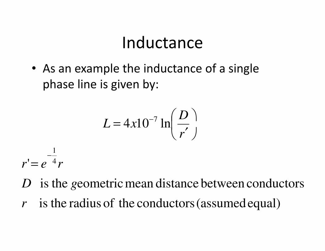
• As an example the inductance of a single
phase line is given by:
ln104 7 DxL −
′=
equal) (assumed conductors theof radius theis
conductorsbetween distancemean eometric theis
'
ln104
4
1
r
gD
rer
rxL
−
=
′
=
Inductance
• The heavy dependence on conductor mounting geometry means that each phase can have a different inductance.
• Unbalance inductances lead to unbalanced impedances which lead to unbalanced impedances which lead to unbalanced currents and voltages.
• This can be solved by switching the positions of the conductors periodically over the length of the line. This called transmission line transposition.
Inductance
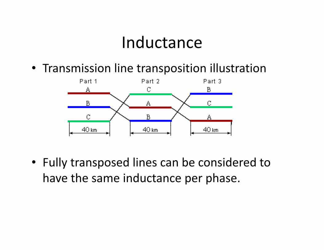
• Transmission line transposition illustration
• Fully transposed lines can be considered to
have the same inductance per phase.
Capacitance
• Exists between lines, lines and neutral and
lines and the earth.
• Capacitor formed by lines acting as plates and
the air acting as the dielectric.the air acting as the dielectric.
• Total capacitance in a phase depends on
conductor shape and arrangement geometry.
• Practically very difficult to calculate.
Capacitance
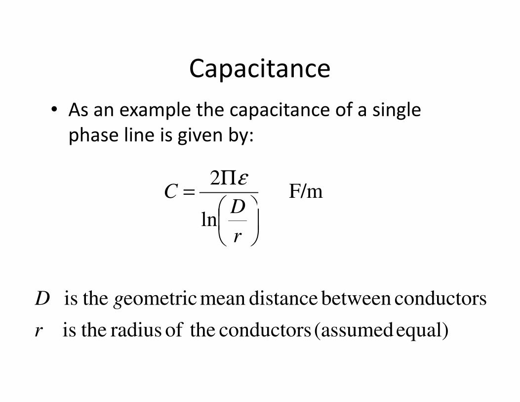
• As an example the capacitance of a single
phase line is given by:
F/m 2
D
C
Π=
ε
equal) (assumed conductors theof radius theis
conductorsbetween distancemean eometric theis
F/m
ln
r
gD
r
DC
=
Capacitance
• Line capacitance gives rise to a shunt
admittance on the line. This is a path for
current to flow between the lines.
• The shunt capacitance can be significant for • The shunt capacitance can be significant for
long lines.
• The capacitance between the lines also supply
vars to the system that must be taken into
account if the line length is significant.
Line Models (Equivalent Circuits)
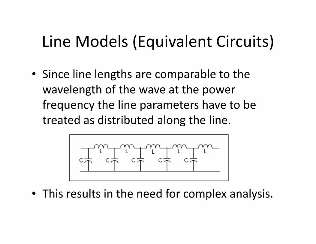
• Since line lengths are comparable to the
wavelength of the wave at the power
frequency the line parameters have to be
treated as distributed along the line.treated as distributed along the line.
• This results in the need for complex analysis.
Line Models (Equivalent Circuits)
• Fortunately for certain line lengths
simplifications can be made.
• These simplifications classify transmission
lines in short, medium and long.lines in short, medium and long.
• These simplifications lends themselves to
simpler analyses but still give accurate results
in practice.
Line Models – Short Line
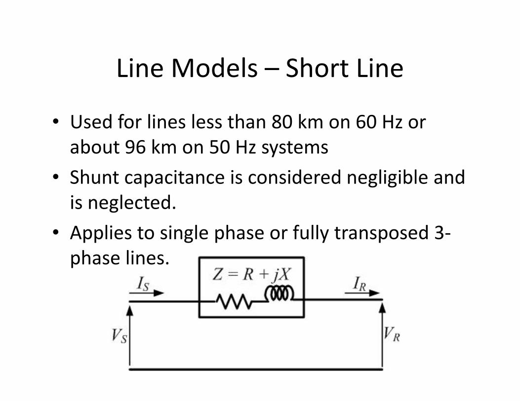
• Used for lines less than 80 km on 60 Hz or
about 96 km on 50 Hz systems
• Shunt capacitance is considered negligible and
is neglected.is neglected.
• Applies to single phase or fully transposed 3-
phase lines.
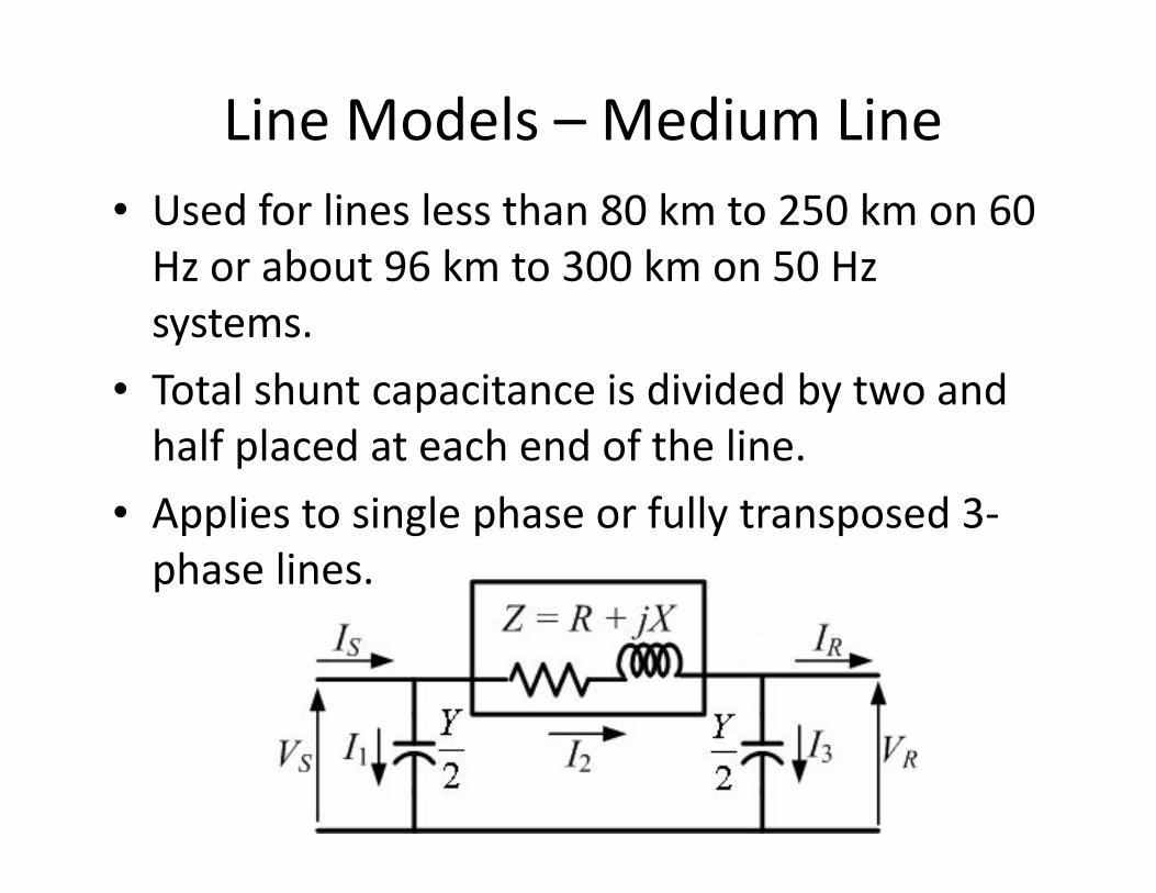
Line Models – Medium Line
• Used for lines less than 80 km to 250 km on 60
Hz or about 96 km to 300 km on 50 Hz
systems.
• Total shunt capacitance is divided by two and
half placed at each end of the line.half placed at each end of the line.
• Applies to single phase or fully transposed 3-
phase lines.
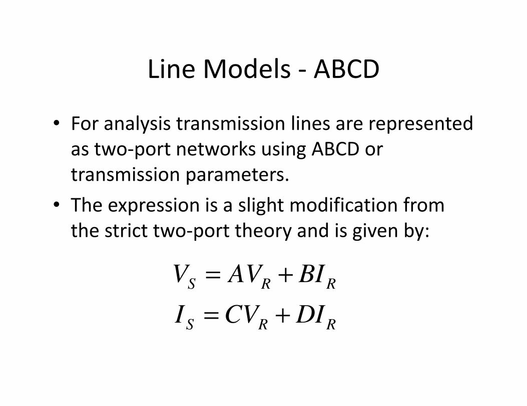
Line Models - ABCD
• For analysis transmission lines are represented
as two-port networks using ABCD or
transmission parameters.
• The expression is a slight modification from • The expression is a slight modification from
the strict two-port theory and is given by:
RRS
RRS
DICVI
BIAVV
+=
+=
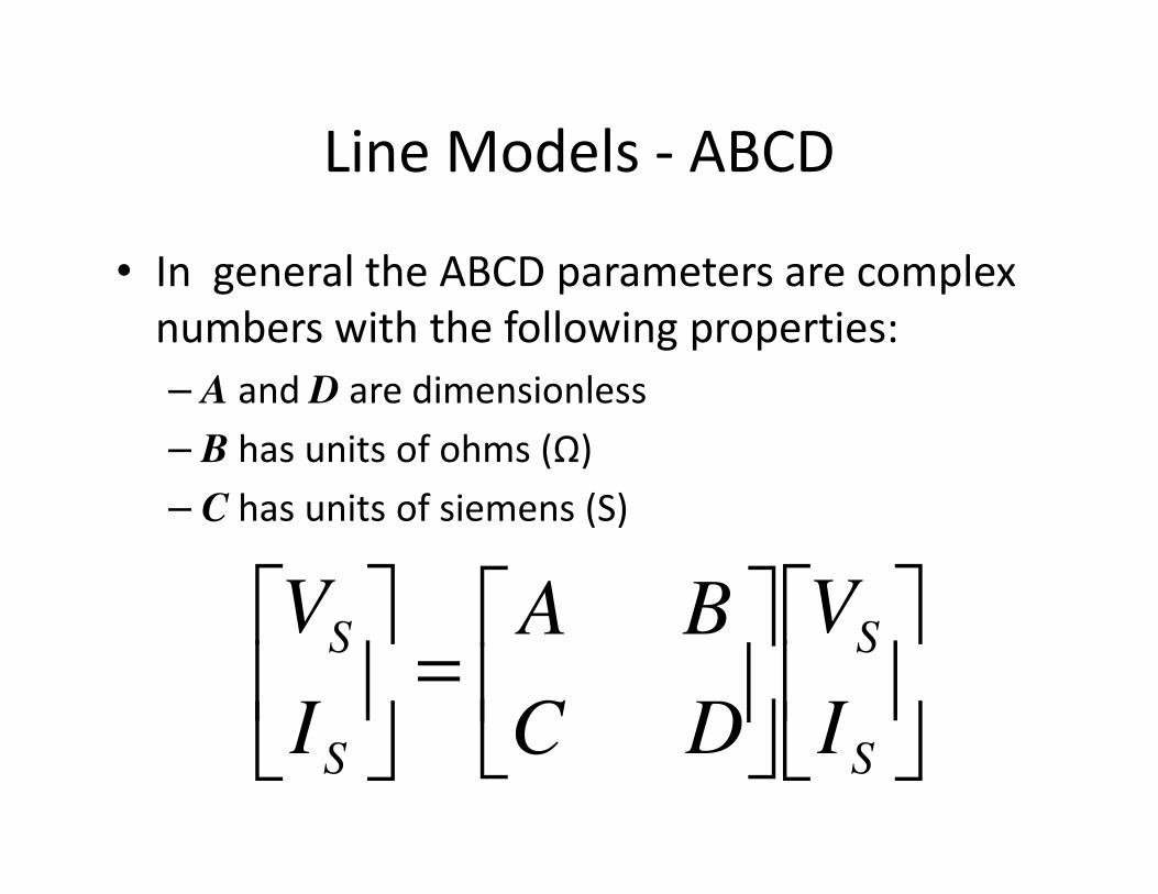
Line Models - ABCD
• In general the ABCD parameters are complex
numbers with the following properties:
– A and D are dimensionless
– B has units of ohms (Ω)– B has units of ohms (Ω)
– C has units of siemens (S)
=
S
S
S
S
I
V
DC
BA
I
V
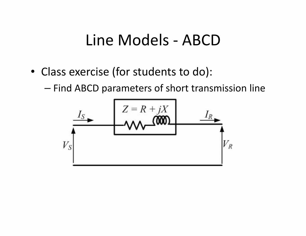
Line Models - ABCD
• Class exercise (for students to do):
– Find ABCD parameters of short transmission line
Line Models - ABCD
• Class exercise (for students to do):
– Solution
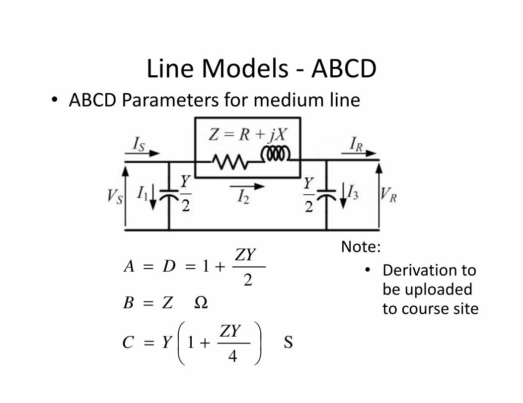
Line Models - ABCD• ABCD Parameters for medium line
S 4
1
21
+=
Ω=
+==
ZYYC
ZB
ZYDA
Note:
• Derivation to be uploaded to course site
Line Voltage Regulation
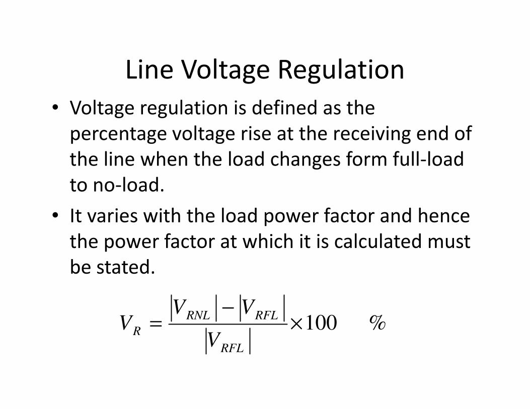
• Voltage regulation is defined as the
percentage voltage rise at the receiving end of
the line when the load changes form full-load
to no-load.
• It varies with the load power factor and hence • It varies with the load power factor and hence
the power factor at which it is calculated must
be stated.
% 100×−
=RFL
RFLRNL
RV
VVV

Line Voltage Regulation
• Voltage regulation is normally maintained at
5% in practice.
• It varies with the load power factor and hence
the power factor at which it is calculated must
be stated.be stated.
• The no-load voltage can be given by:
voltageend sending theis
S
SRNL
V
A
VV =
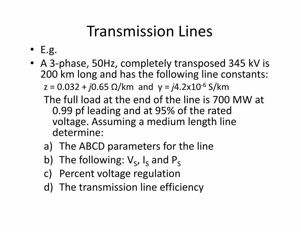
Transmission Lines• E.g.
• A 3-phase, 50Hz, completely transposed 345 kV is 200 km long and has the following line constants:z = 0.032 + j0.65 Ω/km and y = j4.2x10-6 S/km
The full load at the end of the line is 700 MW at 0.99 pf leading and at 95% of the rated voltage. Assuming a medium length line 0.99 pf leading and at 95% of the rated voltage. Assuming a medium length line determine:
a) The ABCD parameters for the line
b) The following: VS, IS and PS
c) Percent voltage regulation
d) The transmission line efficiency
Line Models – Lossless Line
• Since transmission lines are generally designed to have a low resistance it is possible to neglect the resistance when performing analysis and still get accurate enough results.
• The resulting line is a lossless line and the following parameters are defined for it:following parameters are defined for it:
– Surge impedance
– Propagation constant
– Surge impedance loading (SIL)
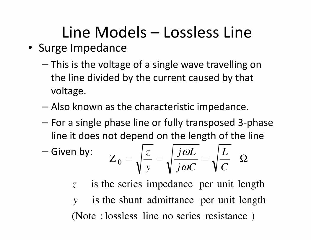
Line Models – Lossless Line• Surge Impedance
– This is the voltage of a single wave travelling on
the line divided by the current caused by that
voltage.
– Also known as the characteristic impedance.
– For a single phase line or fully transposed 3-phase – For a single phase line or fully transposed 3-phase
line it does not depend on the length of the line
– Given by:
)resistance series no line lossless :(Note
lengthunit per admittanceshunt theis
length unit per impedance series theis
Z 0
y
z
C
L
Cj
Lj
y
zΩ===
ω
ω
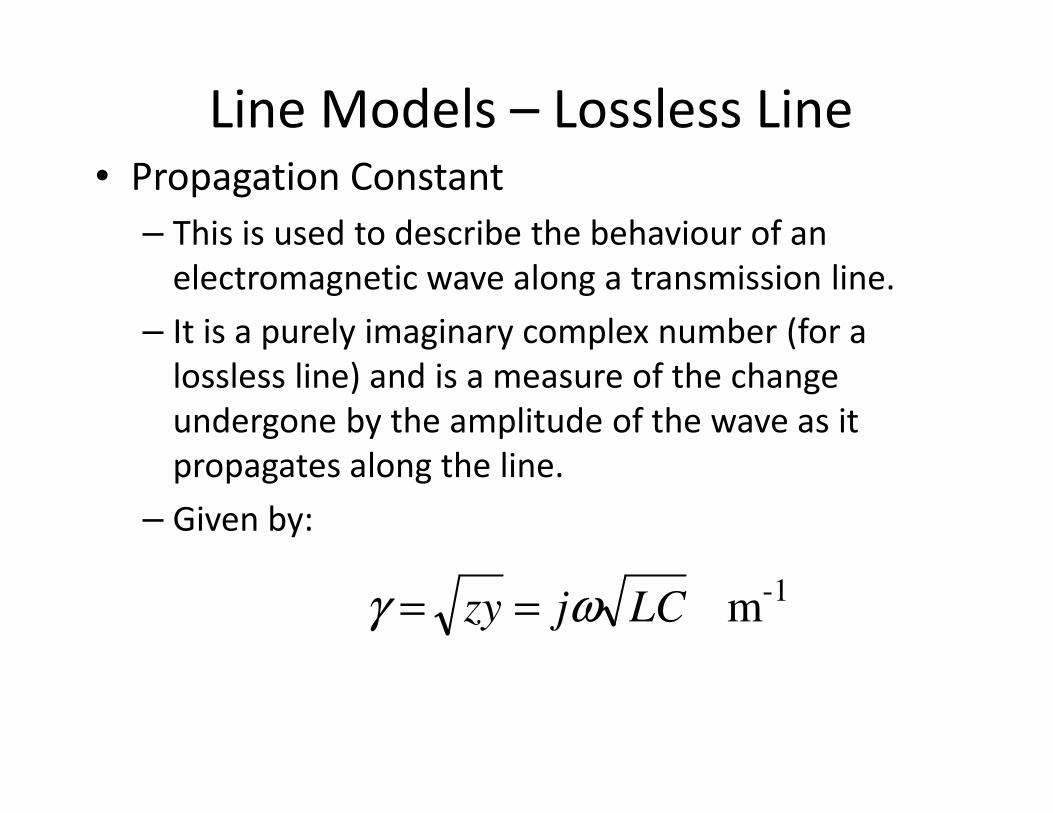
Line Models – Lossless Line• Propagation Constant
– This is used to describe the behaviour of an
electromagnetic wave along a transmission line.
– It is a purely imaginary complex number (for a
lossless line) and is a measure of the change
undergone by the amplitude of the wave as it undergone by the amplitude of the wave as it
propagates along the line.
– Given by:
-1m LCjzy ωγ ==
Line Models – Lossless Line
• Surge Impedance Loading (SIL)
– This is the power delivered by a lossless
transmission line to a load that has an impedance
equal to the surge impedance of the line.
– The line can be a single phase line or one phase to – The line can be a single phase line or one phase to
neutral of a three phase line.
– When the line is operating at it’s SIL the voltage
magnitude is the same along the entire length of
the line (note that this isn’t generally the case for
long lines), it’s voltage profile is then termed as
flat.
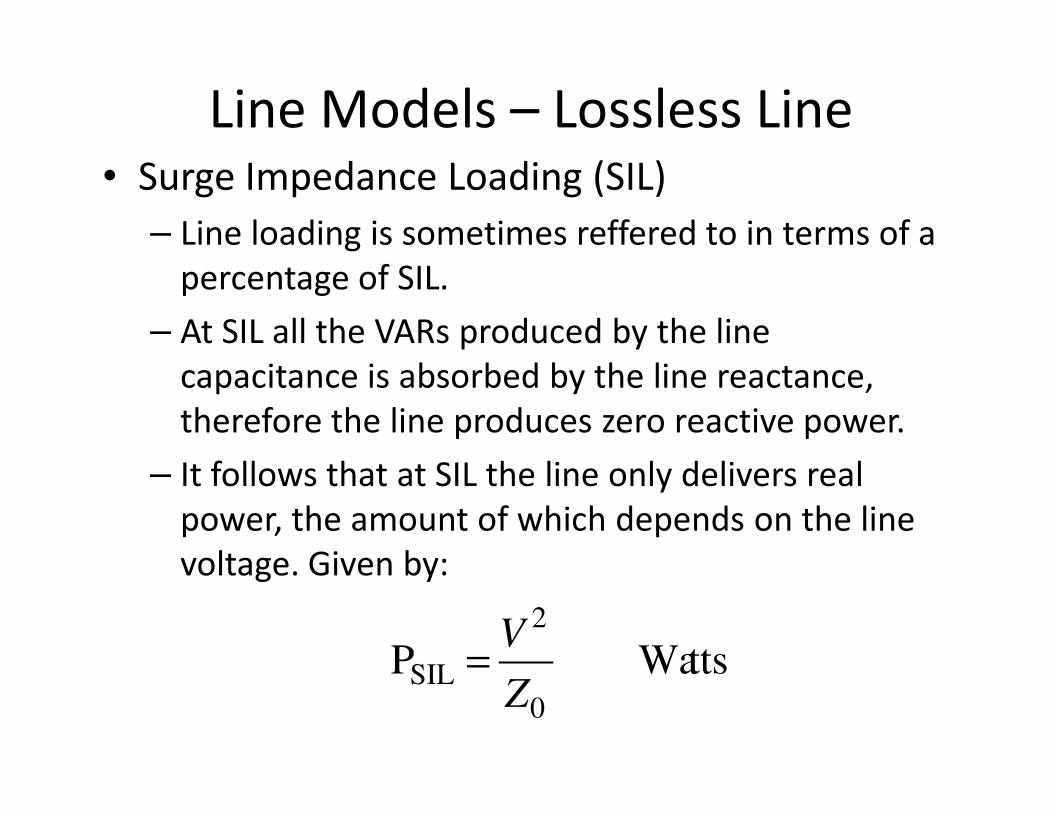
Line Models – Lossless Line• Surge Impedance Loading (SIL)
– Line loading is sometimes reffered to in terms of a
percentage of SIL.
– At SIL all the VARs produced by the line
capacitance is absorbed by the line reactance,
therefore the line produces zero reactive power.therefore the line produces zero reactive power.
– It follows that at SIL the line only delivers real
power, the amount of which depends on the line
voltage. Given by:
tts WaP0
2
SILZ
V=

Line Models – Long Line
• Used for lines longer than 250 km on 60 Hz or
about 300 km on 50 Hz systems
• Series impedance and shunt capacitance are
distributed along the line and hence
differential equations are need to solve for differential equations are need to solve for
line voltage and current.
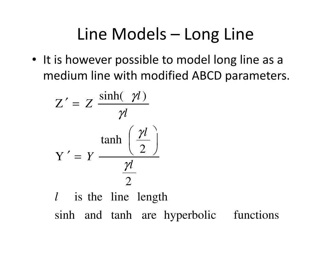
Line Models – Long Line
• It is however possible to model long line as a
medium line with modified ABCD parameters.
)sinh(
Z
l
l
lZ
γ
γ
γ
=′
functions hyperbolic are tanh and sinh
length line theis
2
2tanh
Y
l
l
l
Yγ
γ
=′
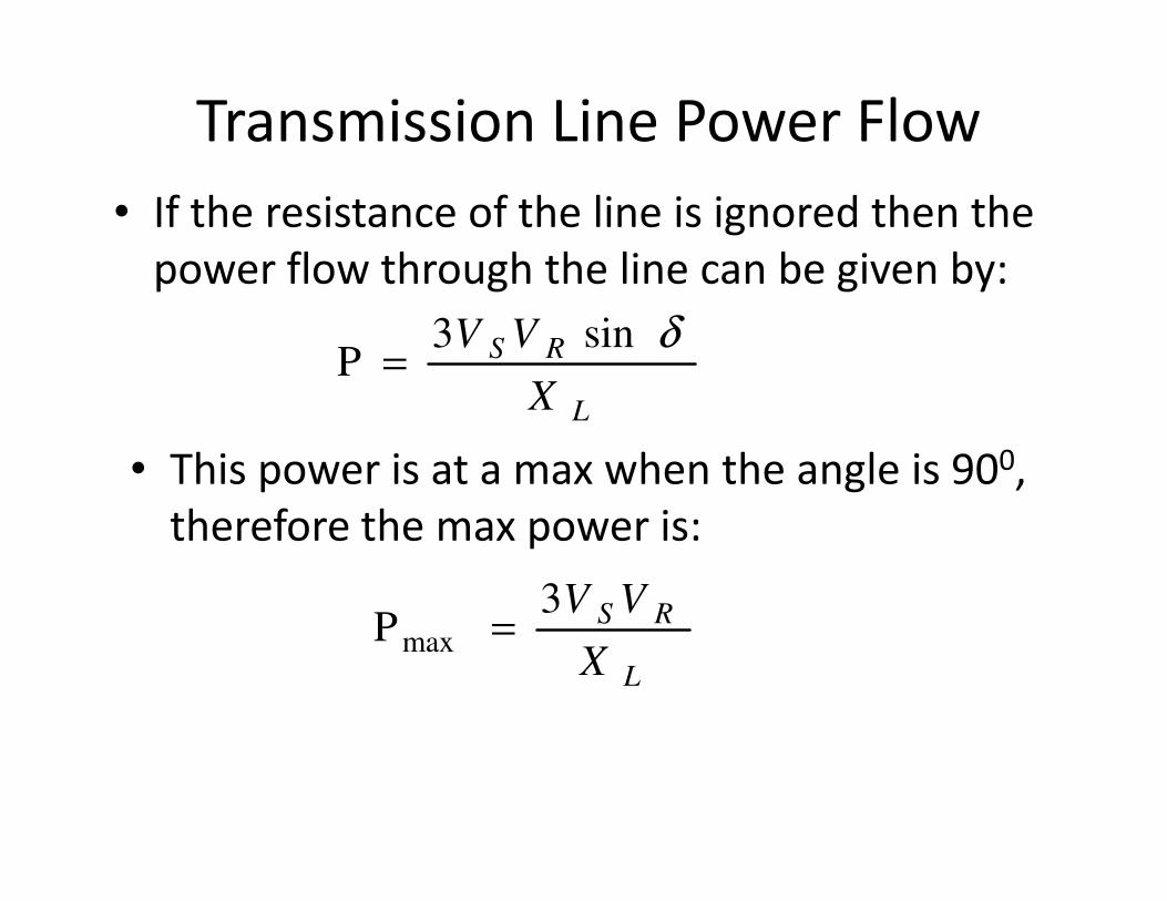
Transmission Line Power Flow
• If the resistance of the line is ignored then the
power flow through the line can be given by:
sin3
PL
RS
X
VV δ=
• This power is at a max when the angle is 900, • This power is at a max when the angle is 900,
therefore the max power is:
3
Pmax
L
RS
X
VV=
Transmission Line Power Flow
• The maximum power handling capability of a
transmission line is inversely proportional to
its series reactance.
• Therefore some very long lines include series • Therefore some very long lines include series
capacitors to reduce the total series reactance
and increase the power transferred.
Transmission Line Power Flow
• More examples

ENDEND