Elastic–plastic analysis of o•-center cracks in cylindrical...
25
Elastic–plastic analysis of o-center cracks in cylindrical structures Robert Firmature a , Sharif Rahman b, * a IBM Printing Systems Company, Boulder, CO 80301, USA b Department of Mechanical Engineering, The University of Iowa, Iowa City, IA 52242, USA Received 1 July 1999; received in revised form 13 October 1999; accepted 19 November 1999 Abstract This paper presents new elastic and elastic–plastic finite element solutions of the J-integral for a pipe containing o-center through-wall cracks under pure bending. The analysis is based on a three-dimensional nonlinear finite element method and small-strain theory. One hundred and five analyses were performed using the ABAQUS commercial code for a wide variety of crack sizes, o-center crack angles, and material hardening exponents. The results from these analyses show that the J-integral values at the two crack fronts of an o-center crack are unequal due to the loss of symmetry with respect to the bending plane of the pipe. In addition, the J-integral is larger, and hence, critical at the crack front which is farther away from the bending axis of the pipe. This is because, at that crack front, the tensile stress is larger and the component of the applied bending moment about the crack centerline has a further crack-opening eect. Also at this crack front, the J values can be lower or slightly higher than those of a symmetrically centered crack, depending on the crack size and o-centered angle. For the crack front that is closer to the bending axis, the J values are always lower than those of a symmetrically centered crack. This implies that the load-carrying capacity of a pipe is usually larger for an o-center crack than that for a symmetrically centered crack. Finally, based on these finite element solutions, new analytical expressions of J-integral were developed for fracture analysis of pipes containing o-center cracks. 7 2000 Elsevier Science Ltd. All rights reserved. Keywords: J-integral; Elastic–plastic fracture mechanics; O-center crack; Pipe; Through-wall crack; Leak-before-break; J-esti- mation method 1. Introduction Fracture analysis of pipes with circumferential cracks is an important task for leak-before-break Engineering Fracture Mechanics 66 (2000) 15–39 0013-7944/00/$ - see front matter 7 2000 Elsevier Science Ltd. All rights reserved. PII: S0013-7944(99)00135-6 www.elsevier.com/locate/engfracmech * Corresponding author. Tel.: +1-319-335-5679; fax: +1-319-335-5669. E-mail address: [email protected] (S. Rahman).
Transcript of Elastic–plastic analysis of o•-center cracks in cylindrical...
Elastic±plastic analysis of o�-center cracks in cylindricalstructures
Robert Firmaturea, Sharif Rahmanb,*aIBM Printing Systems Company, Boulder, CO 80301, USA
bDepartment of Mechanical Engineering, The University of Iowa, Iowa City, IA 52242, USA
Received 1 July 1999; received in revised form 13 October 1999; accepted 19 November 1999
Abstract
This paper presents new elastic and elastic±plastic ®nite element solutions of the J-integral for a pipe containingo�-center through-wall cracks under pure bending. The analysis is based on a three-dimensional nonlinear ®niteelement method and small-strain theory. One hundred and ®ve analyses were performed using the ABAQUS
commercial code for a wide variety of crack sizes, o�-center crack angles, and material hardening exponents. Theresults from these analyses show that the J-integral values at the two crack fronts of an o�-center crack are unequaldue to the loss of symmetry with respect to the bending plane of the pipe. In addition, the J-integral is larger, and
hence, critical at the crack front which is farther away from the bending axis of the pipe. This is because, at thatcrack front, the tensile stress is larger and the component of the applied bending moment about the crack centerlinehas a further crack-opening e�ect. Also at this crack front, the J values can be lower or slightly higher than those of
a symmetrically centered crack, depending on the crack size and o�-centered angle. For the crack front that is closerto the bending axis, the J values are always lower than those of a symmetrically centered crack. This implies thatthe load-carrying capacity of a pipe is usually larger for an o�-center crack than that for a symmetrically centeredcrack. Finally, based on these ®nite element solutions, new analytical expressions of J-integral were developed for
fracture analysis of pipes containing o�-center cracks. 7 2000 Elsevier Science Ltd. All rights reserved.
Keywords: J-integral; Elastic±plastic fracture mechanics; O�-center crack; Pipe; Through-wall crack; Leak-before-break; J-esti-
mation method
1. Introduction
Fracture analysis of pipes with circumferential cracks is an important task for leak-before-break
Engineering Fracture Mechanics 66 (2000) 15±39
0013-7944/00/$ - see front matter 7 2000 Elsevier Science Ltd. All rights reserved.
PII: S0013-7944(99 )00135-6
www.elsevier.com/locate/engfracmech
* Corresponding author. Tel.: +1-319-335-5679; fax: +1-319-335-5669.
E-mail address: [email protected] (S. Rahman).
(LBB) [1,2] and pipe ¯aw evaluations [3]. Fig. 1 shows the cross-sectional geometry of three idealizedcircumferential cracks, which illustrate a simple through-wall crack (TWC), an internal surface crack,and a complex crack in a pipe. These cracks are frequently used to evaluate structural integrity andreliability of degraded piping systems. To evaluate its integrity under bending or combined bending andtension (pressure-induced) loads, the fracture response characteristics, such as crack-openingdisplacement and J-integral, are typically evaluated by assuming that these ¯aws are symmetricallyplaced with respect to the bending plane of the pipe (see Fig. 1). This is usually justi®ed with thereasoning that the tensile stress due to bending is largest at the center of this symmetric crack. However,in real life, fabrication imperfections occur randomly around the pipe circumference. Additionally,during the normal operating condition of a power plant, the stress component due to pressure is farmore signi®cant than that due to bending. As such, the postulated ¯aw in LBB analysis may be o�-centered and can thus be located anywhere around the pipe circumference. The likelihood of a crackbeing o�-centered can be further emphasized in light of the argument that a symmetric bending planeunder normal operating stress may become very di�erent under normal and safe-shutdown earthquakestress, due to the uncertainty in the seismic ground motion [4±6].
Analytical and computational methods for fracture analysis of symmetrically±centered,circumferential, TWC pipes subjected to pure bending, pure tension, and combined bending and tensionare well-developed. During the U.S. Nuclear Regulatory Commission's Short Cracks in Piping andPiping Welds Program [7], the currently available methods were evaluated by extensive comparisons withthe experimental data. Two major technical reports, published by Brust et al. [8] and Rahman et al. [4],describe these methods and associated results involving various pipe geometries, crack sizes, andmaterial properties. Although much has been learned about the behavior of symmetrically centeredcracks, the current methods are incapable of predicting fracture response and crack growth behavior ofo�-center cracks, even though o�-center cracks may be a concern of practical interest for both LBB andpipe ¯aw evaluations [9]. Hence, a fracture-mechanics study of o�-center cracks is an exciting researcharea for improved evaluation of piping and pressure vessel integrity.
In the past, Rahman and coworkers investigated the crack-opening behavior of TWC pipes with bothsymmetrically centered [10±12] and o�-center [5,6,12] cracks subject to pure bending loads. One of thesestudies developed a computational framework for analyzing o�-center cracks based on the linear-elastic®nite element method (FEM) [5,6]. Pipe-speci®c ®nite element calculations showed that the reducedcrack-opening area (COA) for a pipe with an o�-center crack can be determined by normal analysisprocedures for a symmetrically centered crack via resolution of applied moment and assuming anelliptical crack-opening pro®le. This was an important ®nding for the leak-rate analysis part of LBB,since accuracy in the prediction of COA is more important than that of the entire crack-opening shape.Furthermore, the results indicated that due to reduced COA, a postulated crack size for LBB analysiswill be larger (depending on the o�-center angle) for the o�-center cracks than that for thesymmetrically centered cracks. However, it can also be argued that when a crack is o�-centered, thecrack-driving force, be it stress-intensity factor in linear-elastic fracture or J-integral in elastic±plasticfracture, will be lower than that for a symmetrically centered crack. Hence, an o�-centered crack mayincrease the length of the postulated leaking ¯aw due to reduced crack-opening and cause a detrimentale�ect, but it can also have a bene®cial e�ect on the maximum load-carrying capacity of pipes. In theprevious work of Rahman et al. [5,6], only the crack-opening aspect of o�-center cracks has beenaddressed. No methods have been developed or fracture analyses have been reported yet to predictcrack-driving force and, hence, load-carrying capacity of pipes containing o�-center cracks.
This paper presents new results from elastic and elastic±plastic fracture analyses of circumferentialTWC pipes with o�-center cracks subject to pure bending loads. The analyses are based on a three-dimensional nonlinear FEM and small-strain theory. The analyses were performed for a pipe with aradius-to-thickness ratio of 10 and a wide variety of crack size, o�-center angles, and material hardening
R. Firmature, S. Rahman / Engineering Fracture Mechanics 66 (2000) 15±3916

Fig. 1. Examples of symmetrically centered cracks in pipes: (a) simple through-wall crack, (b) internal part-through surface crack,
and (c) complex crack.
R. Firmature, S. Rahman / Engineering Fracture Mechanics 66 (2000) 15±39 17
characteristics. The ®nite element solutions were studied to evaluate the e�ects of o�-centered cracks onthe J-integral. Subsequently, these FEM results were used to develop new analytical expressions ofin¯uence functions for fracture analysis of pipes containing o�-center cracks.
2. A TWC pipe with an o�-center crack
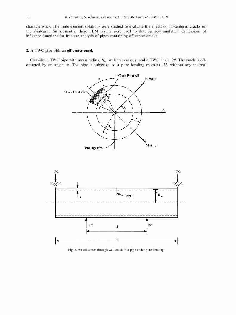
Consider a TWC pipe with mean radius, Rm, wall thickness, t, and a TWC angle, 2y: The crack is o�-centered by an angle, c: The pipe is subjected to a pure bending moment, M, without any internal
Fig. 2. An o�-center through-wall crack in a pipe under pure bending.
R. Firmature, S. Rahman / Engineering Fracture Mechanics 66 (2000) 15±3918
pressure. This loading can be simulated by a four-point bend test as shown in Fig. 2. In this ®gure, S isthe inner span, L is the outer span, and P is the total applied load. The geometric parameters of thiso�-center crack in the cracked section are also de®ned in Fig. 2.
In order to perform elastic±plastic analysis, the material model needs to be de®ned. In this study, itwas assumed that the constitutive law characterizing the material's uniaxial stress±strain �s±e� responsecan be represented by the well-known Ramberg±Osgood model, which is
ee0� s
s0� a
�ss0
�n
�1�
where s0 is the reference stress which can be arbitrary, but is usually assumed to be the yield stress, E isthe modulus of elasticity, e0 � s0=E is the associated reference strain, and a and n are the modelparameters usually chosen from a best ®t of actual laboratory data. Although this representation of thestress±strain curve is not necessary for the ®nite element analysis (FEA), it is needed for most J-estimation methods, which are formulated based on power-law idealization.
3. Elastic±plastic fracture mechanics
The J-integral fracture parameter proposed by Rice [13] has been extensively used in assessing fractureintegrity of cracked engineering structures, which undergo large plastic deformation at the crack tip. Forelastic±plastic problems, its interpretation as the strength of the asymptotic crack-tip ®elds byHutchinson [14] and Rice and Rosengren [15] represents the crux of the basis for ``J-controlled'' crackgrowth behavior. For a cracked body with an arbitrary counter-clockwise path, G around the crack tip,a formal de®nition of J-integral under mode-I condition is
J �def�G
ÿWn1 ÿ Tiui, 1
�dG �2�
where W� � sij deij is the strain energy density with sij and eij representing components of stress andstrain tensors, respectively, ui and Ti � sijnj are the ith components of displacement and tractionvectors, nj is the jth component of unit outward normal to integration path, dG is the di�erential lengthalong contour G, and ui; 1� @ui=@x1 is the di�erentiation of displacement with respect to x1: Here, thesummation convention is adopted for repeated indices.
4. Finite element simulation
The FEM in this study assumed the elastic±plastic constitutive relation given by Eq. (1) and smallstrains. It was based on proportional loading in the crack-tip plastic zone. Hence, the use ofdeformation theory of plasticity and Eq. (1) is entirely appropriate. The plastic deformation wasassumed to be incompressible and independent of hydrostatic stress, 1
3sii: An isotropic hardening rulewas assumed. Under these conditions, the generalized multiaxial stress±strain relation becomes
eij � 1� nE
Sij � 1ÿ 2n3E
slldij � 3
2ae0�se
s0
�nÿ1Sij
s0�3�
where n is Poisson's ratio, dij is the Kronecker delta, Sij � sij ÿ 13skkdij is the deviatoric stress, and s2e �
�32SijSij � is the square of the von Mises equivalent stress. While the analysis is for small strains,
R. Firmature, S. Rahman / Engineering Fracture Mechanics 66 (2000) 15±39 19
nonlinearity enters through Eq. (1) or Eq. (3). Note, Eq. (3) reduces to Eq. (1) for a uniaxial state ofstress.
4.1. Finite element implementation of J
For numerical calculation of J, the energy domain integral methodology [16,17] was used in the FEA.This methodology is versatile, as it can be applied to both quasi-static and dynamic fracture problemswith elastic, plastic, or viscoplastic material response, as well as thermal loading. In addition, thedomain integral formulation is relatively simple to implement numerically in a ®nite element code.
Using the divergence theorem, the contour integral de®ned in Eq. (2) can be expanded into a volumeintegral in three-dimensions over a ®nite domain surrounding the crack tip or crack front. For a linearor nonlinear elastic material under a quasi-static condition, in the absence of body forces, thermalstrains, and crack-face tractions, Eq. (2) for a three-dimensional pipe problem reduces to
J ��V �
�sij@uj@x1ÿWd1i
�@q
@xidV �4�
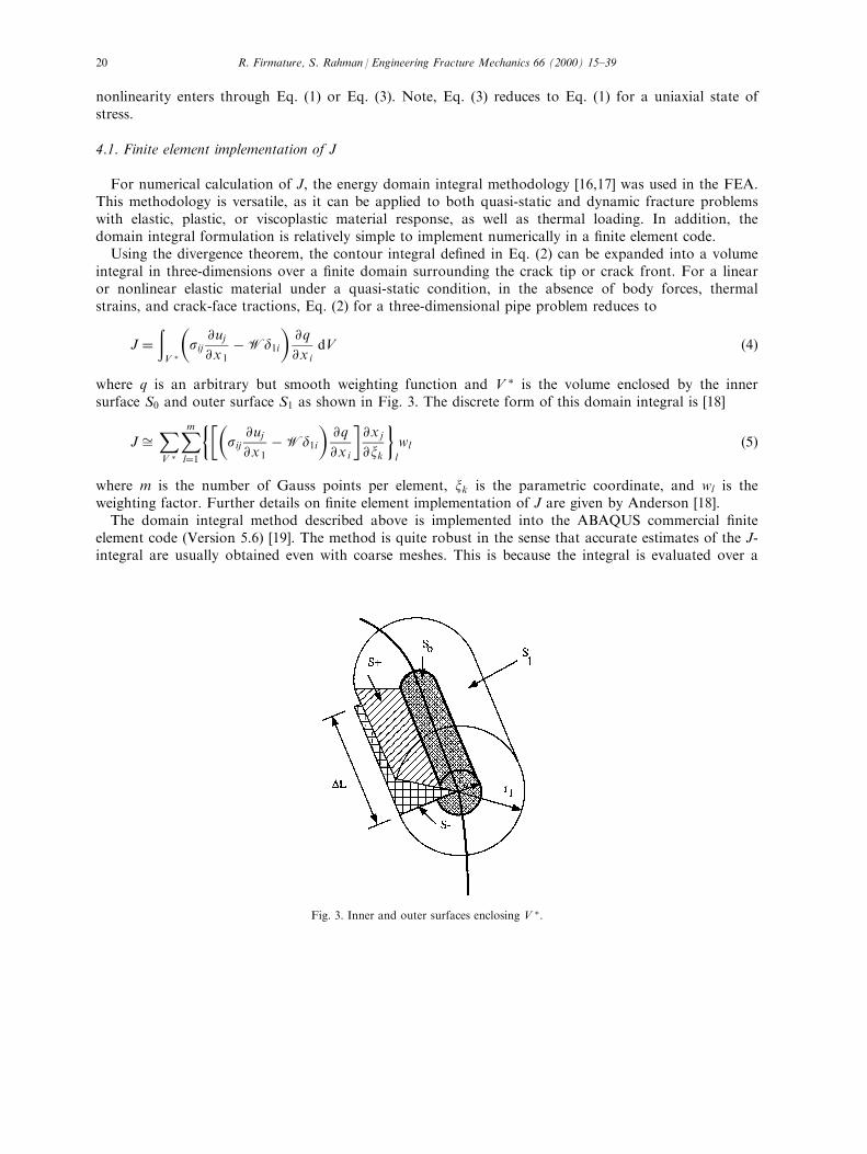
where q is an arbitrary but smooth weighting function and V � is the volume enclosed by the innersurface S0 and outer surface S1 as shown in Fig. 3. The discrete form of this domain integral is [18]
J �XV �
Xml�1
���sij@uj@x1ÿWd1i
�@q
@xi
�@xj
@xk
�l
wl �5�
where m is the number of Gauss points per element, xk is the parametric coordinate, and wl is theweighting factor. Further details on ®nite element implementation of J are given by Anderson [18].
The domain integral method described above is implemented into the ABAQUS commercial ®niteelement code (Version 5.6) [19]. The method is quite robust in the sense that accurate estimates of the J-integral are usually obtained even with coarse meshes. This is because the integral is evaluated over a
Fig. 3. Inner and outer surfaces enclosing V �:
R. Firmature, S. Rahman / Engineering Fracture Mechanics 66 (2000) 15±3920
domain of elements surrounding the crack front, so that the errors in local solution parameters have alesser e�ect on the calculated value.
4.2. Matrix of analysis and ®nite element models
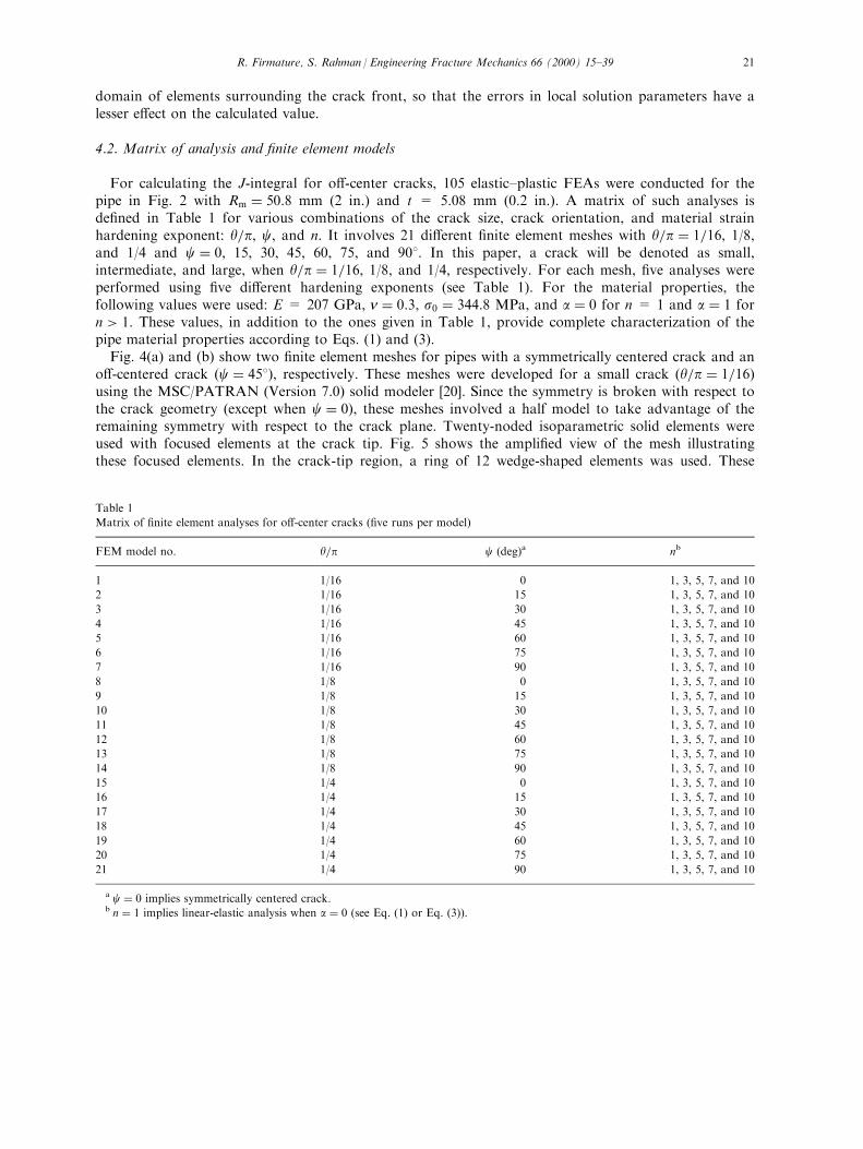
For calculating the J-integral for o�-center cracks, 105 elastic±plastic FEAs were conducted for thepipe in Fig. 2 with Rm � 50:8 mm (2 in.) and t = 5.08 mm (0.2 in.). A matrix of such analyses isde®ned in Table 1 for various combinations of the crack size, crack orientation, and material strainhardening exponent: y=p, c, and n. It involves 21 di�erent ®nite element meshes with y=p � 1=16, 1/8,and 1/4 and c � 0, 15, 30, 45, 60, 75, and 908. In this paper, a crack will be denoted as small,intermediate, and large, when y=p � 1=16, 1/8, and 1/4, respectively. For each mesh, ®ve analyses wereperformed using ®ve di�erent hardening exponents (see Table 1). For the material properties, thefollowing values were used: E = 207 GPa, n � 0:3, s0 � 344:8 MPa, and a � 0 for n = 1 and a � 1 forn > 1: These values, in addition to the ones given in Table 1, provide complete characterization of thepipe material properties according to Eqs. (1) and (3).
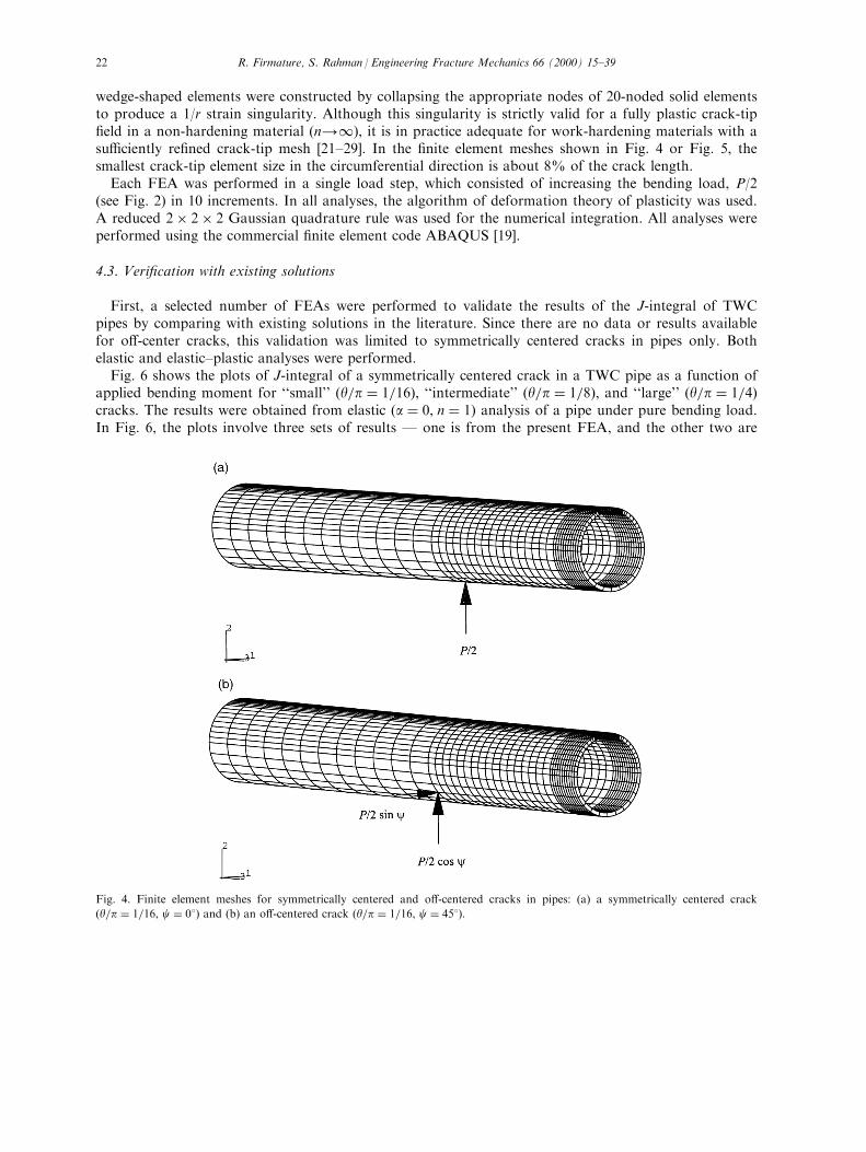
Fig. 4(a) and (b) show two ®nite element meshes for pipes with a symmetrically centered crack and ano�-centered crack �c � 458), respectively. These meshes were developed for a small crack �y=p � 1=16�using the MSC/PATRAN (Version 7.0) solid modeler [20]. Since the symmetry is broken with respect tothe crack geometry (except when c � 0), these meshes involved a half model to take advantage of theremaining symmetry with respect to the crack plane. Twenty-noded isoparametric solid elements wereused with focused elements at the crack tip. Fig. 5 shows the ampli®ed view of the mesh illustratingthese focused elements. In the crack-tip region, a ring of 12 wedge-shaped elements was used. These
Table 1
Matrix of ®nite element analyses for o�-center cracks (®ve runs per model)
FEM model no. y=p c (deg)a nb
1 1/16 0 1, 3, 5, 7, and 10
2 1/16 15 1, 3, 5, 7, and 10
3 1/16 30 1, 3, 5, 7, and 10
4 1/16 45 1, 3, 5, 7, and 10
5 1/16 60 1, 3, 5, 7, and 10
6 1/16 75 1, 3, 5, 7, and 10
7 1/16 90 1, 3, 5, 7, and 10
8 1/8 0 1, 3, 5, 7, and 10
9 1/8 15 1, 3, 5, 7, and 10
10 1/8 30 1, 3, 5, 7, and 10
11 1/8 45 1, 3, 5, 7, and 10
12 1/8 60 1, 3, 5, 7, and 10
13 1/8 75 1, 3, 5, 7, and 10
14 1/8 90 1, 3, 5, 7, and 10
15 1/4 0 1, 3, 5, 7, and 10
16 1/4 15 1, 3, 5, 7, and 10
17 1/4 30 1, 3, 5, 7, and 10
18 1/4 45 1, 3, 5, 7, and 10
19 1/4 60 1, 3, 5, 7, and 10
20 1/4 75 1, 3, 5, 7, and 10
21 1/4 90 1, 3, 5, 7, and 10
a c � 0 implies symmetrically centered crack.b n � 1 implies linear-elastic analysis when a � 0 (see Eq. (1) or Eq. (3)).
R. Firmature, S. Rahman / Engineering Fracture Mechanics 66 (2000) 15±39 21
wedge-shaped elements were constructed by collapsing the appropriate nodes of 20-noded solid elementsto produce a 1/r strain singularity. Although this singularity is strictly valid for a fully plastic crack-tip®eld in a non-hardening material �n41), it is in practice adequate for work-hardening materials with asu�ciently re®ned crack-tip mesh [21±29]. In the ®nite element meshes shown in Fig. 4 or Fig. 5, thesmallest crack-tip element size in the circumferential direction is about 8% of the crack length.
Each FEA was performed in a single load step, which consisted of increasing the bending load, P/2(see Fig. 2) in 10 increments. In all analyses, the algorithm of deformation theory of plasticity was used.A reduced 2� 2� 2 Gaussian quadrature rule was used for the numerical integration. All analyses wereperformed using the commercial ®nite element code ABAQUS [19].
4.3. Veri®cation with existing solutions
First, a selected number of FEAs were performed to validate the results of the J-integral of TWCpipes by comparing with existing solutions in the literature. Since there are no data or results availablefor o�-center cracks, this validation was limited to symmetrically centered cracks in pipes only. Bothelastic and elastic±plastic analyses were performed.
Fig. 6 shows the plots of J-integral of a symmetrically centered crack in a TWC pipe as a function ofapplied bending moment for ``small'' �y=p � 1=16), ``intermediate'' �y=p � 1=8), and ``large'' �y=p � 1=4�cracks. The results were obtained from elastic �a � 0, n � 1� analysis of a pipe under pure bending load.In Fig. 6, the plots involve three sets of results Ð one is from the present FEA, and the other two are
Fig. 4. Finite element meshes for symmetrically centered and o�-centered cracks in pipes: (a) a symmetrically centered crack
�y=p � 1=16, c � 08� and (b) an o�-centered crack �y=p � 1=16, c � 458).
R. Firmature, S. Rahman / Engineering Fracture Mechanics 66 (2000) 15±3922

based on the well-known GE/EPRI J-estimation formula using the elastic in¯uence functions of Kumaret al. [30,31] and Brust et al. [32,33].1 The analyses were continued until M was considerably larger thanthe reference moment, M0, of the pipe, de®ned by Kumar et al. [30,31].2 As seen in Fig. 6, the three setsof results are in close agreement with each other for all crack sizes considered in this study.
In addition to this elastic validation of J, similar comparisons were also made for an elastic±plasticcase with a speci®c value of n = 5. As before, the analyses were conducted for three crack sizes withy=p � 1=16, 1/8, and 1/4. The comparisons of results from this study with the GE/EPRI solutions arepresented in Fig. 7. The elastic±plastic FEM results match very well with the existing solutions. Thisveri®cation gave con®dence in our ®nite element calculations.
4.4. Results and discussions
According to Table 1, 21 ®nite element meshes similar to the ones in Fig. 4 or Fig. 5, were developed[35,36]. For each mesh, ®ve analyses were performed for n = 1, 3, 5, 7, and 10. For brevity, only theresults of the elastic analysis (n = 1) and elastic±plastic (n = 5) analysis will be discussed in this paper.Detailed results are available in Ref. [35].
4.4.1. Elastic analysisFig. 8(a) and (b) show the results of J vs. M plots from purely elastic (n = 1) analyses of small cracks
Fig. 5. Crack-tip mesh re®nement �y=p � 1=16).
1 In both studies by Kumar et al. [30,31] and Brust et al. [32,33], the in¯uence functions de®ned by the GE/EPRI method were
derived from FEAs. The analysis by Kumar et al. involved the ADINA code [34] using nine-noded shell elements. The analysis by
Brust et al. involved the ABAQUS code [19] using 20-noded solid elements.2 According to the GE/EPRI J-estimation formula given by Kumar et al. [30,31], M0�4s0R2
mt�cos y2 ÿ 1
2 sin y�:
R. Firmature, S. Rahman / Engineering Fracture Mechanics 66 (2000) 15±39 23
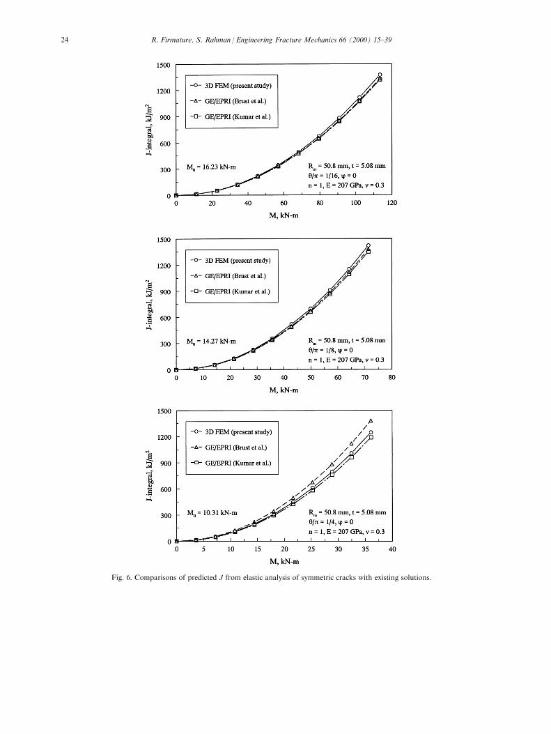
Fig. 6. Comparisons of predicted J from elastic analysis of symmetric cracks with existing solutions.
R. Firmature, S. Rahman / Engineering Fracture Mechanics 66 (2000) 15±3924
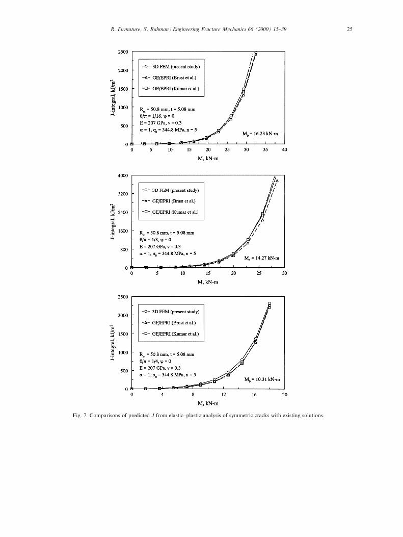
Fig. 7. Comparisons of predicted J from elastic±plastic analysis of symmetric cracks with existing solutions.
R. Firmature, S. Rahman / Engineering Fracture Mechanics 66 (2000) 15±39 25
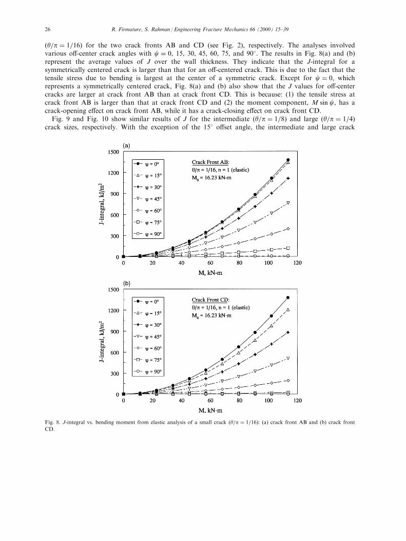
�y=p � 1=16� for the two crack fronts AB and CD (see Fig. 2), respectively. The analyses involvedvarious o�-center crack angles with c � 0, 15, 30, 45, 60, 75, and 908. The results in Fig. 8(a) and (b)represent the average values of J over the wall thickness. They indicate that the J-integral for asymmetrically centered crack is larger than that for an o�-centered crack. This is due to the fact that thetensile stress due to bending is largest at the center of a symmetric crack. Except for c � 0, whichrepresents a symmetrically centered crack, Fig. 8(a) and (b) also show that the J values for o�-centercracks are larger at crack front AB than at crack front CD. This is because: (1) the tensile stress atcrack front AB is larger than that at crack front CD and (2) the moment component, M sin c, has acrack-opening e�ect on crack front AB, while it has a crack-closing e�ect on crack front CD.
Fig. 9 and Fig. 10 show similar results of J for the intermediate �y=p � 1=8� and large �y=p � 1=4�crack sizes, respectively. With the exception of the 158 o�set angle, the intermediate and large crack
Fig. 8. J-integral vs. bending moment from elastic analysis of a small crack �y=p � 1=16): (a) crack front AB and (b) crack front
CD.
R. Firmature, S. Rahman / Engineering Fracture Mechanics 66 (2000) 15±3926

sizes display a behavior similar to the small crack. For these larger cracks with a small o�set, it wasobserved that the J values were actually slightly higher than those for the centered crack case at crackfront AB. This can be explained by noting that for an incremental increase in the o�set angle from thecentered position, crack front AB will be placed into a higher stress region which can lead to theincreased J values as observed in this study. Extending this argument even further, it is postulated thatfor any crack size, there will exist a threshold of o�set angle below which the J values at crack front ABexceed those of the centered crack. Unfortunately, this trend was not captured for the smaller cracks inthis study due to the fact that for computational e�ciency, the mesh was only designed for a 158
Fig. 9. J-integral vs. bending moment from elastic analysis of a medium crack �y=p � 1=8): (a) crack front AB and (b) crack front
CD.
R. Firmature, S. Rahman / Engineering Fracture Mechanics 66 (2000) 15±39 27

increment of the o�set angle. This threshold o�set angle will increase as the crack size increases. Furtherinvestigations should be undertaken to determine this threshold of o�set angle.3
4.4.2. Elastic±plastic analysisElastic±plastic analyses were also performed for a speci®c case of n = 5 to investigate the fracture
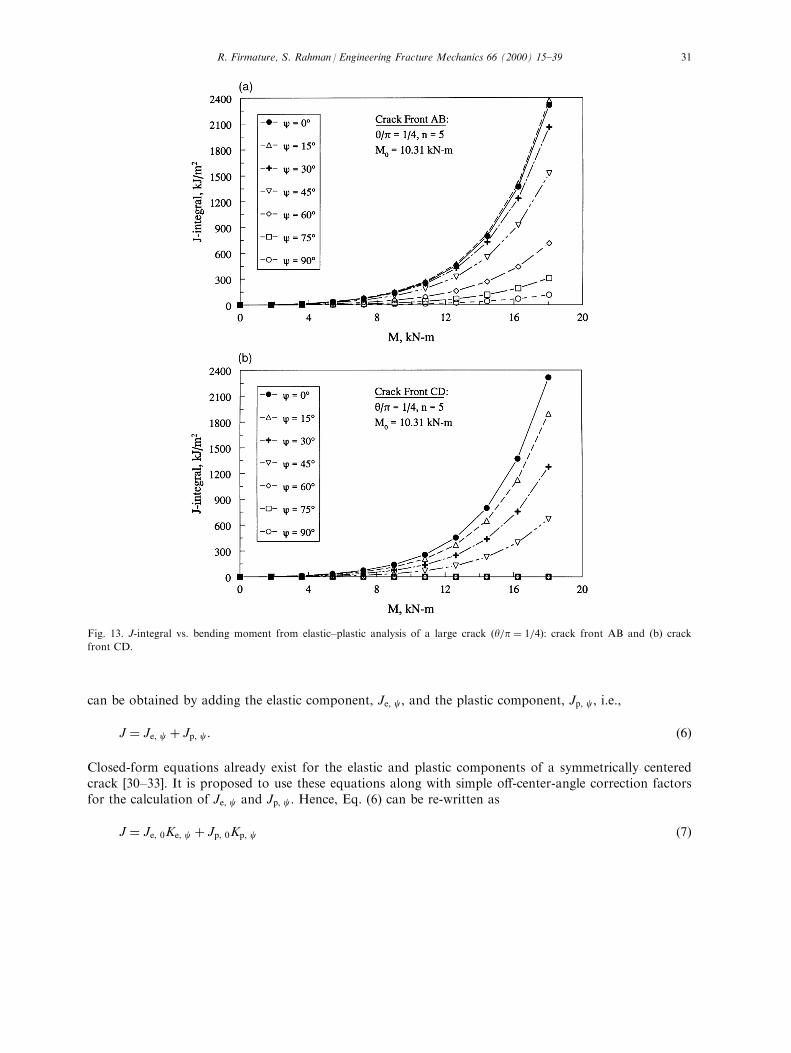
behavior of o�-center cracks in the presence of crack-tip plasticity. The results of these analyses areshown in Figs. 11, 12 and 13 in terms of J vs. M plots for small, intermediate, and large cracks,respectively. As before, the J-integral values are presented for both crack fronts AB and CD and various
Fig. 10. J-integral vs. bending moment from elastic analysis of a large crack �y=p � 1=4): (a) crack front AB and (b) crack front
CD.
3 Upon further investigation, this particular o�set angle threshold was less than 158 for y=p � 1=16:
R. Firmature, S. Rahman / Engineering Fracture Mechanics 66 (2000) 15±3928
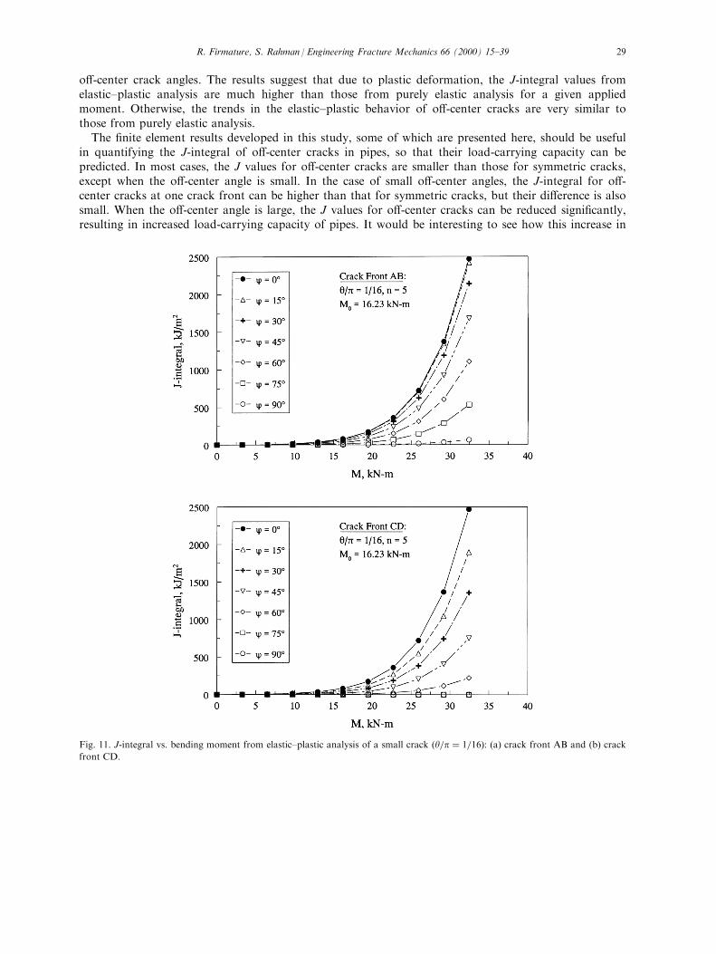
o�-center crack angles. The results suggest that due to plastic deformation, the J-integral values fromelastic±plastic analysis are much higher than those from purely elastic analysis for a given appliedmoment. Otherwise, the trends in the elastic±plastic behavior of o�-center cracks are very similar tothose from purely elastic analysis.
The ®nite element results developed in this study, some of which are presented here, should be usefulin quantifying the J-integral of o�-center cracks in pipes, so that their load-carrying capacity can bepredicted. In most cases, the J values for o�-center cracks are smaller than those for symmetric cracks,except when the o�-center angle is small. In the case of small o�-center angles, the J-integral for o�-center cracks at one crack front can be higher than that for symmetric cracks, but their di�erence is alsosmall. When the o�-center angle is large, the J values for o�-center cracks can be reduced signi®cantly,resulting in increased load-carrying capacity of pipes. It would be interesting to see how this increase in
Fig. 11. J-integral vs. bending moment from elastic±plastic analysis of a small crack �y=p � 1=16): (a) crack front AB and (b) crack
front CD.
R. Firmature, S. Rahman / Engineering Fracture Mechanics 66 (2000) 15±39 29

load-carrying capacity counters the reduced crack-opening for LBB applications. These FEM results canbe used to develop analytical expressions of in¯uence functions and J-integral for fracture analysis ofpipes containing o�-center cracks. These analytical expressions will allow both deterministic andprobabilistic pipe fracture evaluations without any need to perform a full-scale nonlinear FEA. They aredescribed in the next section.
5. A new J-estimation method
Under elastic±plastic conditions and applying the deformation theory of plasticity when the stress±strain curve is modeled by Eq. (1), the total crack driving force, J, for an o�-centered crack of angle c
Fig. 12. J-integral vs. bending moment from elastic±plastic analysis of a medium crack �y=p � 1=8): (a) crack front AB and (b)
crack front CD.
R. Firmature, S. Rahman / Engineering Fracture Mechanics 66 (2000) 15±3930
can be obtained by adding the elastic component, Je, c, and the plastic component, Jp, c, i.e.,
J � Je, c � Jp, c: �6�
Closed-form equations already exist for the elastic and plastic components of a symmetrically centeredcrack [30±33]. It is proposed to use these equations along with simple o�-center-angle correction factorsfor the calculation of Je, c and Jp, c: Hence, Eq. (6) can be re-written as
J � Je, 0Ke, c � Jp, 0Kp, c �7�
Fig. 13. J-integral vs. bending moment from elastic±plastic analysis of a large crack �y=p � 1=4): crack front AB and (b) crack
front CD.
R. Firmature, S. Rahman / Engineering Fracture Mechanics 66 (2000) 15±39 31

where
Je, 0 � ypF�y=p, Rm=t�2 M2
ER3mt
2�8�
and
Jp, 0 � as20E
Rmy
�1ÿ y
p
�h1�y=p, n, Rm=t�
�M
M0
�n�1�9�
are the well-known GE/EPRI equations4 [30±33] for elastic and plastic components of J, respectively,for a symmetrically centered crack, i.e., when c � 0, F�y=p, Rm=t� and h1�y=p, n, Rm=t� are elastic andplastic in¯uence functions for symmetrically centered cracks, M0 is a reference moment, and Ke, c andKp, c are constant elastic and plastic correction factors for o�-center cracks, respectively. Note, ane�ective crack length using plastic-zone-size correction was used in the original GE/EPRI equations [30].In this study, the actual crack length was used in Eqs. (6)±(9) since the plastic component of the J-integral is explicitly accounted for in Eq. (6). See Ref. [4,8] for justi®cation of using actual crack lengthover e�ective crack length. The evaluations of F�y=p, Rm=t� and h1�y=p, n, Rm=t� are described inAppendix A.
By comparing Eqs. (6) and (7), it is easy to show that
Ke, c � Je, c
Je, 0�10�
Kp, c � Jp, c
Jp, 0: �11�
With this new proposed method, i.e., Eq. (7), the J-integral for o�-center cracks can be easily calculatedwhen these two correction factors are prescribed for a given o�-center angle, c:
5.1. Calculation of correction factors
From Eqs. (10) and (11), it can be seen that the proposed correction factors are simply a ratio of theJ values for the o�-centered crack to those of the symmetrically centered crack. Based on theseequations and FEM solutions described in the previous sections, Table 2 shows the results of Ke, c andKp, c at cracks fronts AB and CD for a pipe with Rm=t � 10 and various combinations of y=p, c, and n.For an o�-center angle of 0, the correction factors should have a value of 1, as is shown in Table 2. Forthe intermediate �y=p � 1=8� and large �y=p � 1=4� cracks, it is shown that at the 158 o�set thecorrection factor values are sometimes greater than unity for crack front AB. This agrees with the trenddiscussed earlier in which J values at crack front AB with small o�set angle are larger than the valuesobtained for a symmetrically centered crack. For all other cases, the correction factors are less than 1re¯ecting the fact that most of the time the symmetrically centered crack is more critical than the o�-centered crack. Correction factors close to 0 were also found for o�set angles that move the crack frontCD below the bending axis and, therefore, may cause it to be closed.
4 Note, the well-known GE/EPRI method, which constitutes Eqs. (8) and (9), is one of the many J-estimation methods currently
available for analyzing pipes with symmetrically centered cracks. See Refs. [4,8] for other J-estimation methods.
R. Firmature, S. Rahman / Engineering Fracture Mechanics 66 (2000) 15±3932
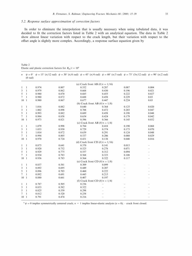
5.2. Response surface approximation of correction factors
In order to eliminate the interpolation that is usually necessary when using tabulated data, it wasdecided to ®t the correction factors listed in Table 2 with an analytical equation. The data in Table 2show almost linear variation with respect to the crack length, but their variation with respect to theo�set angle is slightly more complex. Accordingly, a response surface equation given by
Table 2
Elastic and plastic correction factors for Rm=t � 10a
n c � 08(0 rad)
c � 158 �p=12 rad) c � 308 �p=6 rad) c � 458 �p=4 rad) c � 608 �p=3 rad) c � 758 �5p=12 rad) c � 908 �p=2 rad)
(a) Crack front AB �y=p � 1=16)1 1 0.974 0.807 0.552 0.287 0.087 0.004
3 1 0.979 0.862 0.668 0.430 0.196 0.021
5 1 0.980 0.870 0.685 0.455 0.222 0.027
7 1 0.980 0.872 0.688 0.458 0.229 0.03
10 1 0.980 0.867 0.677 0.447 0.224 0.03
(b) Crack front AB �y=p � 1=8)1 1 1.016 0.882 0.640 0.364 0.125 0.020
3 1 1.002 0.898 0.708 0.472 0.203 0.047
5 1 0.993 0.882 0.689 0.458 0.198 0.048
7 1 0.984 0.858 0.654 0.424 0.179 0.042
10 1 0.973 0.821 0.596 0.366 0.145 0.032
(c) Crack front AB �y=p � 1=4)1 1 1.079 0.998 0.784 0.418 0.190 0.068
3 1 1.033 0.930 0.729 0.374 0.173 0.070
5 1 1.014 0.872 0.639 0.291 0.124 0.048
7 1 0.994 0.805 0.537 0.206 0.080 0.029
10 1 0.970 0.724 0.431 0.138 0.048 0.016
(d) Crack front CD �y=p � 1=16)1 1 0.875 0.641 0.370 0.141 0.015 ±
3 1 0.920 0.752 0.525 0.278 0.071 ±
5 1 0.929 0.775 0.557 0.312 0.094 ±
7 1 0.934 0.783 0.568 0.323 0.108 ±
10 1 0.936 0.783 0.564 0.322 0.117 ±
(e) Crack front CD �y=p � 1=8)1 1 0.837 0.581 0.309 0.099 ± ±
3 1 0.892 0.695 0.449 0.207 ± ±
5 1 0.896 0.703 0.460 0.222 ± ±
7 1 0.892 0.691 0.445 0.215 ± ±
10 1 0.880 0.661 0.407 0.197 ± ±
(f) Crack front CD �y=p � 1=4)1 1 0.787 0.505 0.236 ± ± ±
3 1 0.833 0.582 0.322 ± ± ±
5 1 0.825 0.559 0.298 ± ± ±
7 1 0.812 0.520 0.258 ± ± ±
10 1 0.791 0.474 0.216 ± ± ±
a c � 0 implies symmetrically centered crack; n = 1 implies linear-elastic analysis �a � 0); ± crack front closed.
R. Firmature, S. Rahman / Engineering Fracture Mechanics 66 (2000) 15±39 33
KI, c � 1��a0�n� � a1�n�
�yp
��c�
�a2�n� � a3�n�
�yp
��c2 �
�a4�n� � a5�n�
�yp
��c3
��a6�n� � a7�n�
�yp
��c4
is proposed, where KI, c is either Ke, c or Kp, c (i.e., the elastic or plastic correction factor for an o�-centered crack), and ai�n�, i � 0, 1, . . . ,7, are surface ®t coe�cients that depend on the materialhardening parameter, n, for a pipe with a given Rm=t: The coe�cients, ai�n�, can be furtherapproximated by a fourth-order polynomial equation represented by
ai�n� �X4j�0
Dijnj �13�
in which Dij �i � 0, 1, . . . ,7 and j � 0, 1, . . . ,4� are the polynomial coe�cients that solely depend on theRm=t ratio of the pipe. Following least-squares curve-®t of data in Table 2, Dij were estimated and aregiven in Appendix B for a pipe with Rm=t � 10: Using these values of Dij, Fig. 14(a) and (b) show theplots of Ke, c �n � 1� and Kp, c �n � 5�, respectively, as a function of y=p and c for a pipe with Rm=t �10: From these plots, it appears that Eqs. (12) and (13) can accurately represent the data in Table 2. Infact, the square of correlation coe�cient (R-squared statistic) between the surface ®t equations and the®nite element data was at least 99% for all cases considered in this study.
Note, the analytical approximation of KI, c, represented by Eqs. (12) and (13), allows closed-fromevaluation of J-integral for o�-center cracks. This would signi®cantly reduce the computational e�ort inperforming any future probabilistic and crack-growth studies [37,38].
5.3. Limitations of response surface approximation
Even with a very good agreement between the calculated correction factors and their surface ®ts, twovery important limitations still exist. First, because the ®nite element meshes were only designed for 158increments, it is unknown how well the surface ®ts actually describe the behavior of crack front AB foro�set angles lower than 158. It was found that a threshold o�set angle would exist below 158 for each ofthe three crack lengths in this research; however, these threshold values were not determined in thisstudy. It is expected that a small error will exist in this region due to lack of data. For these reasons, itis recommended that the surface ®t equations for crack front AB only be used for o�set angles rangingfrom 15 to 908 and only for crack lengths between 1/16 and 1/4 of the pipe circumference.
The second limitation is also related to the 158 increment of the o�set angle. Due to the set incrementvalues and the varying crack lengths, the ®nal data point for the two smaller cracks correspond to o�setangles well before closure of crack front CD. Because of this, the behavior of crack front CD isunknown from the last data point until closure for the two smaller cracks. However, for y=p � 1=4, the®nal data point may fall at the largest o�set for which front CD is not closed and, hence, adiscontinuity may occur at this point. Hence, the smaller cracks are expected to behave similarly in thesame con®guration. Due to this fact, the surface ®t equations for crack front CD give reasonableapproximations up to crack closure since they show the correct trend of a discontinuity at crack closure.However, since there are no data for the two smaller cracks at the point of crack closure, a region ofextrapolation is needed between the ®nal nonzero data points and the closure line [35]. The crackclosure line is simply a straight line de®ning one edge of the extrapolation region in the y=p±c plane.The crack is closed when c� y > 908: If crack front CD is closed, then a value of zero should be usedfor the correction factor. Otherwise, correction factor data in this area should be used with caution since
R. Firmature, S. Rahman / Engineering Fracture Mechanics 66 (2000) 15±3934

it is in an area of extrapolation. It is also recommended that the surface ®t equations for crack frontCD be used only for crack lengths between 1/16 and 1/4 of the circumference.
6. Summary and conclusions
New elastic and elastic±plastic ®nite element solutions of J-integral are presented for o�-center, TWCsin pipes under pure bending. The analyses involved a three-dimensional nonlinear FEM and small-straintheory. Using the ABAQUS commercial code, 105 analyses were performed for a pipe with a radius-to-thickness ratio of 10 and a wide variety of crack sizes, o�-center angles, and material hardeningexponents. The results show that:
Fig. 14. Elastic and plastic correction factors for Rm=t � 10: (a) elastic correction factors for crack fronts AB and CD (n = 1) and
(b) plastic correction factors for crack fronts AB and CD (n = 5).
R. Firmature, S. Rahman / Engineering Fracture Mechanics 66 (2000) 15±39 35
. The J-integrals of pipes with symmetrically centered TWCs, calculated by the present three-dimensional FEA, compare very well with the existing GE/EPRI solutions.
. For TWCs in pipes, the J-integral for an o�-center crack is smaller than that for a symmetricallycentered crack for most o�set angles. This implies that the load-carrying capacity of a pipe containingan o�-center crack can be higher than that of a pipe containing a symmetrically centered crack.
. A threshold of o�-center angle exists below which the J values of an o�-center crack at the crackfront farther away from the bending axis of the pipe may exceed those of a symmetrically centeredcrack. The threshold o�-center angles found in this study were small, as was their e�ect on the Jvalues.
. The J-integrals at the two crack fronts of an o�-center crack are unequal due to the loss of symmetrywith respect to the bending plane of the pipe. In general, the J-integral is larger, and hence, critical atthe crack front which is farther away from the bending axis of the pipe. This is because, at that crackfront, the tensile stress is larger and the component of applied moment about the crack centerline hasa further crack-opening e�ect.
Finally, the FEM solutions generated in this study were used to develop new analytical expressions ofin¯uence functions and J-integral for fracture analysis of pipes containing o�-center cracks. This wouldsigni®cantly reduce the computational e�ort in performing any future probabilistic and crack-growthstudies.
Acknowledgements
The work presented in this paper was supported by the Faculty Early Career Development Programof the U.S. National Science Foundation (Grant No. CMS-9733058). The program directors were Dr.Sunil Saigal and Dr. Ken Chong.
Appendix A. In¯uence functions for symmetric cracks
In Eq. (8), F�y=p, Rm=t� is a dimensionless elastic in¯uence function that depends on pipe and crackgeometry. According to Rahman [38],
F�y=p, Rm=t� � 1� �A1 A2 A3
8<: �y=p�1:5
�y=p�2:5�y=p�3:5
9=;�B1 B2 B3 B4
8>><>>:1�Rm=t��Rm=t�2�Rm=t�3
9>>=>>; �14�
where Ai (i = 1±3) and Bi (i = 1±4) are constant coe�cients. Let A � fA1 A2 A3 gT and B �fB1 B2 B3 B4 gT be two real vectors with the coe�cients, Ai and Bi as their components,respectively. Using best ®t of ®nite element results, A and B are given by [38]:
A � � 0:006215 0:013304 ÿ0:01838 T �15�
B � � 175:577 91:69105 ÿ5:53806 0:15116T: �16�
In Eq. (9), h1�y=p, n, Rm=t� is a dimensionless plastic in¯uence function that depends on pipe geometry,crack geometry, and material hardening exponent. According to Rahman [38],
R. Firmature, S. Rahman / Engineering Fracture Mechanics 66 (2000) 15±3936

h1�y=p, n, Rm=t� ��1 �y=p� �y=p�2 �y=p�3
2664C00 C10 C20 C30
C01 C11 C21 C31
C02 C12 C22 C32
C03 C13 C23 C33
37758>><>>:1nn2
n3
9>>=>>; �17�
where Cij �i, j � 0±3� are coe�cients which depend on Rm=t and can also be calculated from best ®t of®nite element results [38]. Let C � �Cij �, i, j � 0±3, be a real matrix with the coe�cients, Cij as itscomponents. According to Rahman [38], C is given by:
For Rm=t � 5,
C �
26643:74009 1:43304 ÿ0:10216 0:0023ÿ 0:19759 ÿ10:19727 ÿ0:45312 0:0498936:42507 17:03413 3:36981 ÿ0:21056ÿ70:4846 ÿ14:69269 ÿ2:90231 0:15165
3775 �18�
For Rm=t � 10,
C �
26643:39797 1:31474 ÿ 0:07898 0:00287ÿ 3:07265 4:34242 ÿ 2:48397 0:11476131:7381 ÿ79:02833 16:18829 ÿ0:66912ÿ234:6221 117:0509 ÿ20:30173 0:79506
3775 �19�
For Rm=t � 20,
C �
26644:07828 ÿ 1:55095 0:67206 ÿ 0:0442
ÿ 18:21195 69:92277 ÿ18:41884 1:11308357:4929 ÿ453:1582 108:0204 ÿ 6:56651ÿ602:7576 617:9074 ÿ144:9435 8:9022
3775: �20�
See Ref. [38] for further explanations on how these coe�cients were calculated.
Appendix B. Coe�cients Dij
Let D � �Dij �, i � 0, 1, . . . ,7 and j � 0, 1, . . ., 4, be a real matrix with the coe�cients, Dij, as itscomponents. Following least-squares curve-®t, D for Rm=t � 10 is given by:
At crack front AB,
R. Firmature, S. Rahman / Engineering Fracture Mechanics 66 (2000) 15±39 37
D �
266666666664
0:3528 ÿ0:2522 0:0631 ÿ0:0074 0:00032:7962 ÿ1:0617 0:2940 ÿ0:0266 0:0008ÿ2:9981 1:6897 ÿ0:4233 0:0496 ÿ0:00213:7670 ÿ2:0229 0:3196 ÿ0:0762 0:00472:0620 ÿ1:4627 0:3823 ÿ0:0467 0:0020ÿ7:1406 2:5393 ÿ0:5405 0:1119 ÿ0:0064ÿ0:3596 0:3150 ÿ0:0885 0:0115 ÿ0:00052:3539 ÿ0:5121 0:1318 ÿ0:0327 0:0019
377777777775�21�
At crack front CD,
D �
266666666664
0:1444 ÿ0:2620 0:0651 ÿ0:0064 0:0002ÿ3:1782 2:5246 ÿ0:6779 0:0734 ÿ0:0029ÿ3:3451 2:3779 ÿ0:5637 0:0583 ÿ0:00224:2744 ÿ8:1376 1:9887 ÿ0:2243 0:00942:9435 ÿ2:6898 0:6399 ÿ0:0670 0:0026ÿ0:6972 6:2504 ÿ1:4695 0:1750 ÿ0:0077ÿ0:7191 0:8152 ÿ0:1955 0:0207 ÿ0:0008ÿ0:4701 ÿ1:3246 0:3025 ÿ0:0393 0:0019
377777777775: �22�
References
[1] USNRC. Report to the U.S. Nuclear Regulatory Commission Piping Review Committee. Prepared by Pipe Break Task
Group, NUREG/CR-1061, vol. 3. Washington, DC: U.S. Nuclear Regulatory Commission, November 1984.
[2] Federal Register. Standard Review Plan, Section 3.6.3 Leak-Before-Break Evaluation Procedures. Public comment paper, vol.
52, No. 167. Notices, August 1987. pp. 32626±633.
[3] American Society of Mechanical Engineers, ASME. Boiler and Pressure Vessel Code, Section XI, 1989.
[4] Rahman S, Brust F, Ghadiali N, Choi YH, Krishnaswamy P, Moberg F, Brickstad B, Wilkowski G. Re®nement and
evaluation of crack-opening-area analyses for circumferential through-wall cracks in pipes. NUREG/CR-6300. Washington,
DC: U.S. Nuclear Regulatory Commission, April 1995.
[5] Rahman S, Ghadiali N, Wilkowski G, Bonora N. E�ects of o�-centered crack and restraint of induced bending on the crack-
opening-area analysis of pipes. In: Mehta H, editor. Proceedings of 1995 ASME/JSME Pressure Vessels and Piping
Conference, Honolulu, Hawaii, Fatigue and Fracture Mechanics in Pressure Vessels and Piping, PVP-Vol. 304, 1995. p. 149±
62.
[6] Rahman S, Ghadiali N, Wilkowski G, Bonora N. E�ects of o�-centered crack and restraint of induced bending due to
pressure on the crack-opening-area analysis of pipes. Nuclear Engineering and Design 1997;167:55±67.
[7] Wilkowski GM, et al. Short cracks in piping and piping program. NUREG/CR-4599, vols. 1±3, Nos. 1±2. Washington, DC:
U.S. Nuclear Regulatory Commission, 1991±1994.
[8] Brust FW, Scott P, Rahman S, Ghadiali N, Kilinski T, Francini B, Marschall CW, Miura N, Krishnaswamy P, Wilkowski
GM. Assessment of short through-wall circumferential cracks in pipes Ð experiments and analysis. NUREG/CR-6235.
Washington, DC: U.S. Nuclear Regulatory Commission, April 1995.
[9] Ghadiali N, Rahman S, Choi YH, Wilkowski G. Deterministic and probabilistic evaluations for uncertainty in pipe fracture
parameters in leak-before-break and in-service ¯aw evaluations. Topical Report, NUREG/CR-6443. Washington, DC: U.S.
Nuclear Regulatory Commission, June 1996.
[10] Rahman S, Brust FW, Ghadiali N, Wilkowski G. Crack-opening-area analyses for circumferential through-wall cracks in
pipes. Part I: Analytical models. International Journal of Pressure Vessels and Piping 1998;75(5):357±73.
[11] Rahman S, Brust FW, Ghadiali N, Wilkowski G. Crack-opening-area analyses for circumferential through-wall cracks in
pipes. Part II: Model validations. International Journal of Pressure Vessels and Piping 1998;75(5):375±96.
R. Firmature, S. Rahman / Engineering Fracture Mechanics 66 (2000) 15±3938
[12] Rahman S, Brust FW, Ghadiali N, Wilkowski G. Crack-opening-area analyses for circumferential through-wall cracks in
pipes. Part III: O�-center cracks, restraint of bending, thickness transition, and weld residual stresses. International Journal of
Pressure Vessels and Piping 1998;75(5):397±415.
[13] Rice JR. A path independent integral and the approximate analysis of strain concentration by notches and cracks. Journal of
Applied Mechanics 1968;35:379±86.
[14] Hutchinson JW. Singular behavior at the end of a tensile crack in a hardening material. Journal Mech Phys Solids
1968;16:13±31.
[15] Rice JR, Rosengren GF. Plane strain deformations near a crack tip in a power-law hardening material. Journal Mech Phys
Solids 1968;16:1±12.
[16] Shih CF, Moran B, Nakamura T. Energy release rate along a three-dimensional crack front in a thermally stressed body.
International Journal of Fracture 1986;30:79±102.
[17] Moran B, Shih CF. A general treatment of crack tip contour integrals. International Journal of Fracture 1987;35:295±310.
[18] Anderson TL. Fracture mechanics: fundamentals and applications, 2nd ed. Boca Raton, FL: CRC Press, 1995.
[19] ABAQUS, User's Guide and Theoretical Manual, Version 5.6. Hibbitt, Karlsson, and Sorensen, Pawtucket, RI, 1997.
[20] MSC/PATRAN, User's Guide and Theoretical Manual, Version 7. The MacNeal±Schwendler Corporation, Los Angeles, CA,
1997.
[21] Wilkowski GM, et al. Degraded piping program Ð phase II, ®nal and semiannual reports. NUREG/CR-4082, vols. 1±8.
Washington, DC: U.S. Nuclear Regulatory Commission, 1985±1989.
[22] Schmidt RA, Wilkowski G, May®eld M. The international piping integrity research group (IPIRG) program Ð an overview.
Proceedings of 11th International Conference on Structural Mechanics in Reactor Technology, Paper G23/1, August 1991.
[23] Hopper A, May®eld M, Olson R, Scott P, Wilkowski G. Overview of the IPIRG-2 program Ð seismic loaded cracked pipe
system experiments. Proceedings of 13th International Conference on Structural Mechanics in Reactor Technology, Division
F, Paper F12-1, August 1995.
[24] Rahman S, Olson R, Rosen®eld A, Wilkowski G. Summary of results from the IPIRG-2 Round-Robin analyses. NUREG/
CR-6337. Washington, DC: U.S. Nuclear Regulatory Commission, February 1996.
[25] Krishnaswamy P, Scott P, Choi Y, Mohan R, Rahman S, Brust F, Wilkowski G. Fracture behavior of short circumferentially
surface-cracked pipe. Topical Report, NUREG/CR-6298. Washington, DC: U.S. Nuclear Regulatory Commission, November
1995.
[26] Scott P, Francini R, Rahman S, Rosen®eld A, Wilkowski G. Fracture evaluations of fusion line cracks in nuclear pipe
bimetallic welds. Topical Report, NUREG/CR-6297. Washington, DC: U.S. Nuclear Regulatory Commission, April 1995.
[27] Rahman S, Brust F. An estimation method for evaluating energy release rates of circumferential through-wall cracked pipe
welds. Engineering Fracture Mechanics 1992;43(3):417±30.
[28] Rahman S, Brust F. Elastic±plastic fracture of circumferential through-wall cracked pipe welds subject to bending. Journal of
Pressure Vessel Technology 1992;114(4):410±6.
[29] Rahman S, Wilkowski G, Brust F. Fracture analysis of full-scale pipe experiments on stainless steel ¯ux welds. Nuclear
Engineering and Design 1996;160:77±96.
[30] Kumar V, German MD, Wilkening WW, Andrews WR, deLorenzi HG, Mowbray DF. Advances in elastic±plastic fracture
analysis. EPRI NP-3607. Palo Alto, CA: Electric Power Research Institute, 1984.
[31] Kumar V, German M. Elastic±plastic fracture analysis of through-wall and surface ¯aws in cylinders. EPRI Topical Report,
NP-5596. Palo Alto, CA: Electric Power Research Institute, January 1988.
[32] Brust F, Rahman S, Ghadiali N. Elastic±plastic analysis of small cracks in tubes. Journal of O�shore Mechanics and Arctic
Engineering 1995;117(1).
[33] Brust F, Rahman S, Ghadiali N. Elastic±plastic analysis of small cracks in tubes. In: Proceedings of 11th International
Conference of O�shore Mechanics and Arctic Engineering, Calgary, Canada, June. 1992.
[34] ADINA, User's Guide and Theoretical Manual. Report AE81-1, ADINA Engineering, Watertown, MA, 1984.
[35] Firmature R. Elastic±plastic analysis of o�-centered cracks in cylindrical structures. A Thesis for Master of Science, The
University of Iowa, Iowa City, IA: Department of Mechanical Engineering, July 1998.
[36] Rahman S, Firmature R. Elastic±plastic analysis of o�-centered cracks in cylindrical structures. In: Rahman S, editor.
Proceedings of 1998 ASME/JSME Pressure Vessels and Piping Conference, San Diego, CA, Fatigue, Fracture and Residual
Stresses, PVP-Vol. 373. July 1998. pp. 489±509.
[37] Rahman S, Chen G, Firmature R. Probabilistic elastic±plastic analysis of o�-centered cracks in cylindrical structures. In:
Rahman S, editor. Proceedings of 1999 ASME Pressure Vessels and Piping Conference, Boston, MA, Probabilistic and
Environmental Aspects of Fracture and Fatigue, PVP-Vol. 390. August 1999.
[38] Rahman S. A stochastic model for elastic±plastic fracture analysis of circumferential through-wall-cracked pipes subject to
bending. Engineering Fracture Mechanics 1995;52(2).
R. Firmature, S. Rahman / Engineering Fracture Mechanics 66 (2000) 15±39 39