
Heavy duty diesel engine oil technology trends 重负荷柴油发动机油技术趋势 lubrizol

1
陆用发电机组柴油机补充说明书
Supplement to Operation and Maintenance Manual
for Land Generating Set Engines
(135 系列、G128 系列、D114 系列、H 系列)
(135 series, G128 series ,D114 series and H series)
文件编号 No. :S00011695+03
上海柴油机股份有限公司
2012 年 7 月
Shanghai Diesel Engine Company, Ltd.
July 2012

2
前 言
欢迎和感谢您选用上柴动力!
上海柴油机股份有限公司是拥有六十多年历史的国家特大型专业柴油机设计制造企业。
柴油机产品采用国际先进技术,引领行业创新潮流,产品已成熟形成135、G128、D114、C121、
H、E、W180等系列,广泛用于汽车、工程机械、船舶舰艇、发电设备等动力配套。企业信
誉卓著,“东风”品牌为中国驰名商标,被评为“中国名牌产品”。产品优质可靠,先后通
过ISO9001、QS9000质量体系认证。服务完善周到,全国有600多个销售服务网点,能快速有
效地解决您的一切后顾之忧。
上柴各系列发电用柴油机是根据柴油发电机组的使用特点和性能在各系列基本型的基础
上进行开发和研制的,能够满足用户对高品质发电动力机的各种需求;柴油机功率覆盖范围
广,可作为常用、备用、急用等柴油发电机组的配套动力。柴油机可以与斯坦福、马拉松、
西门子、利莱森玛等各种品牌发电机配套。可广泛应用于工矿、通信、国防、建筑、农林等
领域。
本说明书叙述了 135 系列、G128 系列、D114 系列、H 系列电站用柴油机的主要技术参
数、结构及安装、使用方法等,是《135 系列柴油机使用保养说明书》、《G128 系列柴油机使
用保养说明书》、《发动机操作与保养手册(D114)》、《SC9DF 系列柴油机使用保养说明书》、
《H 系列柴油机使用保养说明书》有关电站机型的补充说明书,关于各系列柴油机具体操作、
使用、保养、维修等内容还需参考原各系列柴油机的使用保养说明书。
用户在使用各系列的柴油机前,还请认真阅读各系列对照的使用保养说明书及本说明书,
了解这些机型的主要结构、性能及使用方法,以便正确使用柴油机。
随着技术的不断提高和产品不断的更新、改进,本手册的部分内容会与实际机型有所差
异,除定期修改再版外,不再另行通知,敬请用户注意。

3
Foreword
Welcome and thank you for your selection of SDEC’s Diesel Engine!
Shanghai Diesel Engine Company, Ltd. (SDEC), a large state enterprise, has manufactured diesel
engines professionally for over 60 years. Its diesel engines, adopting world advanced technology,
lead a new trend in the industry and its mature products such as 135 series, G128 series, D114 series,
C121 series, H series, E series and W 180 series are widely applied in automobile, construction
machinery, marine, electric generation. SDEC enjoys reputation for its good products. DONG
FENG is a famous national brand and awarded as China Famous Trademark. The products are
good and reliable and SDEC’s quality assurance system has passed certification of ISO 9001, QS
9001, QS 9000.
SDEC’s products for generating sets are developed based on the base engines of all aforesaid series
engines and can meet requirements of customers for high quality generating equipment. The
engines have broad power ranges and can be used as powers for normal, standby and emergent
generators. The engines can be applied to various branded generators such as STAMFORD,
MARATHON, SIEMANS and LEROY-SOMER, which are widely used in mining,
telecommunication, national defense, construction as well as agriculture and forestry.
This manual, containing main technical data, structure, installation and operation of 135 series, C128
series, D114 series and H series engines for generating sets, is a supplement to Operation and
Maintenance Manual for 135 Series Diesel Engine, Operation and Maintenance Manual for G128
Series Diesel Engine, Operation and Maintenance Manual for D114 Series Diesel Engine, Operation
and Maintenance Manual for SC9DF Series Diesel Engine, as well as Operation and Maintenance
Manual for H Series Diesel Engine. For detailed operation and maintenance of these series engines, it
is need to refer to the above respective operation and maintenance manuals.
Read this manual together with the above corresponding manual carefully before operating your
engine in order to fully understand the structure, performance and usage of the engine and operate it
in a proper way.
Some engine models described in this manual may differ from the engine you have brought due to
constant product improvement. This manual is subject to change without notice and SDEC will
update the manual on a regular base.
4
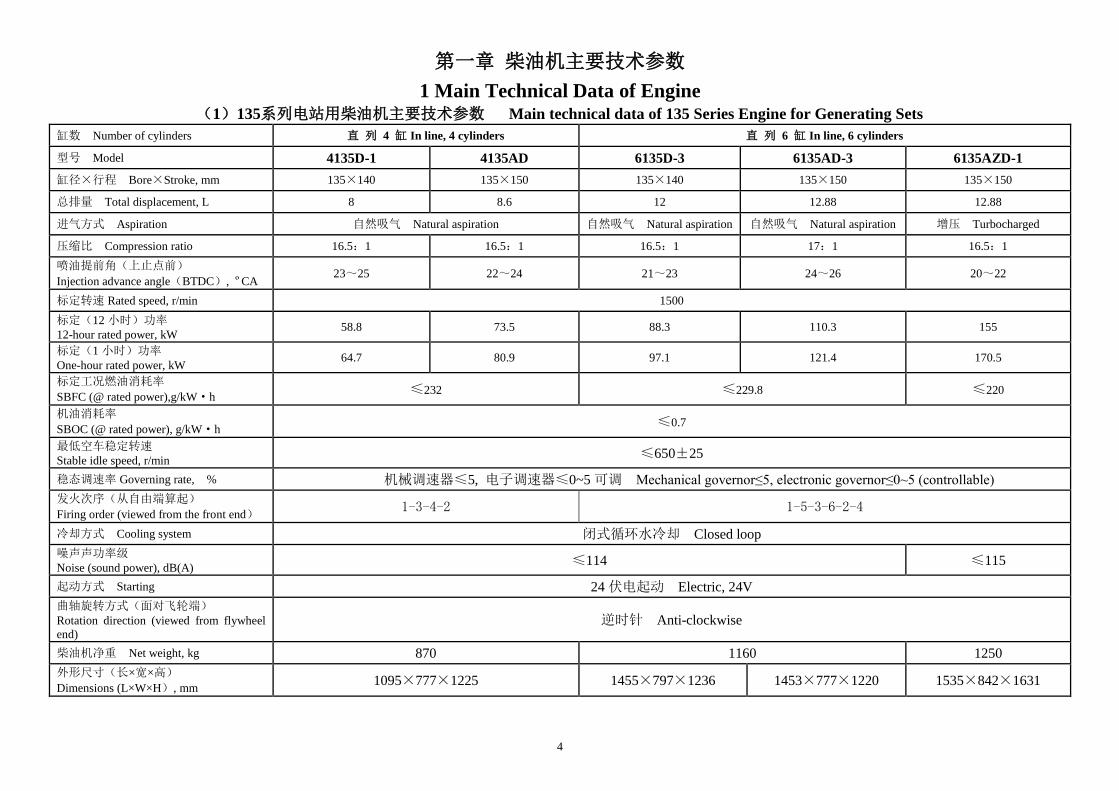
第一章 柴油机主要技术参数
1 Main Technical Data of Engine (1)135系列电站用柴油机主要技术参数 Main technical data of 135 Series Engine for Generating Sets
缸数 Number of cylinders 直 列 4 缸 In line, 4 cylinders 直 列 6 缸 In line, 6 cylinders
型号 Model 4135D-1 4135AD 6135D-3 6135AD-3 6135AZD-1
缸径×行程 Bore×Stroke, mm 135×140 135×150 135×140 135×150 135×150
总排量 Total displacement, L 8 8.6 12 12.88 12.88
进气方式 Aspiration 自然吸气 Natural aspiration 自然吸气 Natural aspiration 自然吸气 Natural aspiration 增压 Turbocharged
压缩比 Compression ratio 16.5:1 16.5:1 16.5:1 17:1 16.5:1
喷油提前角(上止点前)
Injection advance angle(BTDC), ºCA 23~25 22~24 21~23 24~26 20~22
标定转速 Rated speed, r/min 1500
标定(12 小时)功率 12-hour rated power, kW
58.8 73.5 88.3 110.3 155
标定(1 小时)功率 One-hour rated power, kW
64.7 80.9 97.1 121.4 170.5
标定工况燃油消耗率
SBFC (@ rated power),g/kW·h ≤232 ≤229.8 ≤220
机油消耗率
SBOC (@ rated power), g/kW·h ≤0.7
最低空车稳定转速 Stable idle speed, r/min
≤650±25
稳态调速率 Governing rate, % 机械调速器≤5, 电子调速器≤0~5 可调 Mechanical governor≤5, electronic governor≤0~5 (controllable)
发火次序(从自由端算起)
Firing order (viewed from the front end) 1-3-4-2 1-5-3-6-2-4
冷却方式 Cooling system 闭式循环水冷却 Closed loop
噪声声功率级 Noise (sound power), dB(A)
≤114 ≤115
起动方式 Starting 24 伏电起动 Electric, 24V
曲轴旋转方式(面对飞轮端) Rotation direction (viewed from flywheel
end) 逆时针 Anti-clockwise
柴油机净重 Net weight, kg 870 1160 1250
外形尺寸(长×宽×高)
Dimensions (L×W×H), mm 1095×777×1225 1455×797×1236 1453×777×1220 1535×842×1631
5
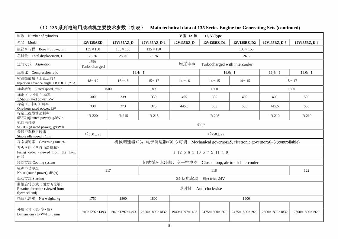
(1)135 系列电站用柴油机主要技术参数(续表) Main technical data of 135 Series Engine for Generating Sets (continued)
缸数 Number of cylinders V 型 12 缸 12, V-Type
型号 Model 12V135AZD 12V135AZLD 12V135AZLD-1 12V135BZLD 12V135BZLD1 12V135BZLD2 12V135BZLD-3 12V135BZLD-4
缸径×行程 Bore×Stroke, mm 135×150 135×150 135×150 135×155
总排量 Total displacement, L 25.76 25.76 25.76 26.6
进气方式 Aspiration 增压
Turbocharged 增压中冷 Turbocharged with intercooler
压缩比 Compression ratio 16.4:1 16.0:1 16.4:1 16.0:1
喷油提前角(上止点前)
Injection advance angle(BTDC), ºCA 18~19 16~18 15~17 14~16 14~15 14~15 15~17
标定转速 Rated speed, r/min 1500 1800 1500 1800
标定(12 小时)功率 12-hour rated power, kW
300 339 339 405 505 459 405 505
标定(1 小时)功率 One-hour rated power, kW
330 373 373 445.5 555 505 445.5 555
标定工况燃油消耗率 SBFC (@ rated power), g/kW·h
≤220 ≤215 ≤215 ≤205 ≤210 ≤210
机油消耗率 SBOC (@ rated power), g/kW·h
≤0.7
最低空车稳定转速 Stable idle speed, r/min
≤650±25 ≤750±25
稳态调速率 Governing rate, % 机械调速器≤5,电子调速器≤0~5 可调 Mechanical governor≤5, electronic governor≤0~5 (controllable)
发火次序(从自由端算起) Firing order (viewed from the front
end) 1-12-5-8-3-10-6-7-2-11-4-9
冷却方式 Cooling system 闭式循环水冷却、空—空中冷 Closed loop, air-to-air intercooler
噪声声功率级 Noise (sound power), dB(A)
117 118 122
起动方式 Starting 24 伏电起动 Electric, 24V
曲轴旋转方式(面对飞轮端) Rotation direction (viewed from
flywheel end) 逆时针 Anti-clockwise
柴油机净重 Net weight, kg 1750 1800 1800 1900
外形尺寸(长×宽×高)
Dimensions (L×W×H), mm 1940×1297×1493 1940×1297×1493 2600×1800×1832 1940×1297×1493 2475×1800×1920 2475×1800×1920 2600×1800×1832 2600×1800×1920

6
(2) G128系列电站用柴油机主要技术参数 Main technical data of G128 series engine for generating sets
型号 Mode G128ZLD/ZLD5 G128ZLD2/ ZLD6 G128ZLD1/ ZLD8 G128 ZLD11/ZLD12
型式 Type 单列、立式、直接喷射式 、“ω”燃烧室、六缸、四冲程
In line, 4 strokes, 6 cylinders, direct injection, “ω” combustion chamber
缸径×行程 Bore×Stroke, mm 135×150
总排量 Total displacement, L 12.88
压缩比 Compression ratio 17:1 16: 1
喷油提前角(上止点前)
Injection advance angle(BTDC), ºCA 15±1 15~16/15±1 15~16/16±1 14~15/15±1
进气方式 Aspiration 废气涡轮增压、增压中冷 Turbocharged, turbocharged with intercooler
标定(持续)功率
Rated continuous power, kW 187 206 236 280
超负荷功率 Over power, kW 206 227 260 308
标定转速 Rated speed, r/min 1500 / 1800 1500 / 1800 1500 / 1800 1500 / 1800
标定工况燃油耗率
SBFC (@ rated power), g/kW·h ≤210
机油消耗率
SBOC (@ rated power), g/kW·h ≤0.7
稳态调速率 Governing rate, % 机械调速器≤5,电子调速器≤0~5 可调 Mechanical governor≤5, electronic governor≤0~5 (controllable)
发火次序(从自由端算起)
Firing order (viewed from the
front end)
1-5-3-6-2-4
冷却方式 Cooling system 闭式循环水冷却、水—空中冷
Closed loop, water-to-air intercooler
闭式循环水冷却、空—空中冷
Closed loop, air-to-air intercooler
起动方式 Starting 24 伏电起动 Electric, 24V
曲轴旋转方式(面对飞轮端)
Rotation direction (viewed from
flywheel end)
逆时针 Anti-clockwise
柴油机净重 Net weight, kg 1200±50 1200±50
外 形 尺 寸 ( 长 × 宽 × 高 )
Dimensions (L×W×H), mm 1633×810×1490 1805×810×1550 1505×1063×1372 1581×835×1362

7
(3) D114系列电站用柴油机主要技术参数
Main technical data of D114 series engine for generating sets
柴油机型号 Model SC8D220D2 SC8D250D2 SC9D280D2 SC9D340D2
型 式 Type 直列,4冲程,增压、增压中冷
In line, 4 strokes, turbocharged, turbocharged with intercooler
气缸数 Number of cylinders 6
缸径×行程 Bore×Stroke, mm 114×135 114×144
排气量 Total displacement, L 8.27 8.82
压缩比 Compression ratio 18:1 16.5:1
喷油提前角(上止点前)
Injection advance angle
(BTDC), ºCA
6±0.5 8~9
标定转速 Rated speed, r/min 1500
标定功率 Rated power, kW 146 168 185 228
超负荷功率 Over power, kW 160 185 204 250
调速方式 Type of governor 电子调速器 Electronic governor
稳态调速率 Governing rate,% 0~5可调 0~5 (controllable)
点 火 顺 序 Firing order
(viewed from the front end) 1-5-3-6-2-4
额定功率燃油消耗率
SBFC (@ rated power), g/kW. h ≤200 ≤196
起动方式 Starting 电起动(24V) Electric, 24V
机油消耗率
SBOC (@ rated power), g/kW. h ≤0.3
最低空载转速
Stable idle speed, r/min ≤900
曲轴旋转方向
Rotation direction 逆时针(从飞轮端看) Anti-clockwise (viewed from flywheel end)
柴油机外型尺寸
Dimensions (L×W×H),mm 1455×730×1190 1578×778×1290
净重 Net weight, kg 660 840

8
(4) H系列电站用柴油机主要技术参数
Main technical data of H series engine for generating sets
柴油机型号 Model SC4H160D2 SC4H180D2 SC7H230D2 SC7H250D2
型 式 Type
直列、四冲程、水冷、直接喷射式、增压中冷、四气门
In line, 4 strokes, water-cooled, direct injection , turbocharged with
intercooler,4 valves
气缸数 Number of cylinders 4 6
缸径×行程 Bore×Stroke, mm 105×124
排气量 Total displacement, L 4.29 6.44
压缩比 Compression ratio 16:1
喷油提前角(上止点前)
Injection advance angle
(BTDC), ºCA
11 10 12 12
标定转速 Rated speed, r/min 1500
标定功率 Rated power, kW 105 120 154 168
超负荷功率 Over power, kW 116 132 170 185
调速方式 Type of governor 电子调速器 Electronic governor
稳态调速率 Governing rate,% 0~5可调 0~5 (controllable)
点 火 顺 序 Firing order
(viewed from the front end) 1-3-4-2 1-5-3-6-2-4
额定功率燃油消耗率
SBFC (@ rated power), g/kW. h ≤198
起动方式 Starting 电起动(24V) Electric, 24V
机油消耗率
SBOC (@ rated power), g/kW. h ≤0.35 ≤0.2
最低空载转速
Stable idle speed, r/min ≤900
曲轴旋转方向
Rotation direction 逆时针(从飞轮端看) Anti-clockwise (viewed from flywheel end)
柴油机外型尺寸
Dimensions (L×W×H),mm 1053×717×1158 1343×741×1267
净重 Net weight, kg 380 500

9
第二章 柴油机外形图
2 Engine Outlines
(1)直列4缸及6缸外形安装图 In-line 4-, and 6-cylinder engines
0
尺寸 Dimension
机型 Model
A1 A2 A3 A4 A5 B1 B2 B3 B4 B5 C C1 C2
4135AZD/AZD-1/AZD-2 1093 172.5 405 745.5 20 372 372 22 347 347 1283 395 150
4135AD 1095 112 458 745.5 20 405 372 22 347 347 1236 450 150
6135D-3/AD-1 1453 0 643 1085.5 20 405 392 25 258 258 1287 460 150
6135D-5 1453 0 643 1085.5 20 405 372 25 258 258 1287 460 150
6135AD-3 1494 0 684 1085.5 61 405 372 25 258 258 1287 460 150
6135JZD/6135AZD-1 1435 100 635 1085.5 20 405 392 25 347 347 1321 450 150
注:当 A5=61 时,为 SAE1#飞轮壳,其相应在表中的尺寸 A1、A3 加 41,A2 减 41
Note: When A5 is 61, flywheel housing will be SAE 1, and A1 as well as A3 should be added with 41 respectively,
while A2 should be abstracted by 41.
(Weight
center)
(Tota
l H
eig
ht)
A1 (to front end face) Flywheel
end face
10
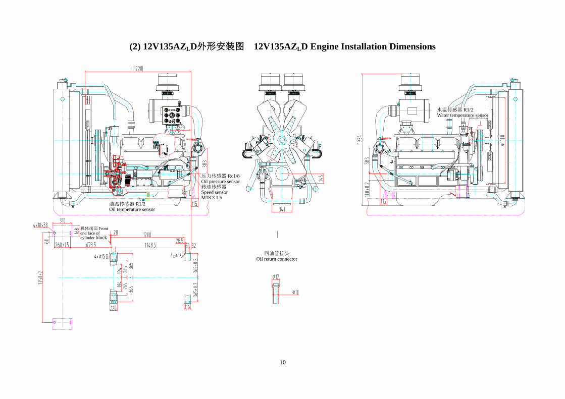
(2) 12V135AZLD外形安装图 12V135AZLD Engine Installation Dimensions
0
仪表控制箱
℃
MPa
0.4
转速
油温
油压(左)
ON
START
OFF
MPa
0.4
0
电流
油压(右)
超速停车
℃
充电油压报警(左)
水温(左)
℃
油压报警(右)
水温(右)
回油管接头 Oil return connector
油温传感器 R1/2 Oil temperature sensor
压力传感器 Rc1/8 Oil pressure sensor 转速传感器 Speed sensor M18×1.5
机体端面 Front end face of cylinder block
水温传感器 R1/2 Water temperature sensor

11
(3) 12V135BZLD外形安装图 12V135BZLD Engine Installation Dimensions
上
40
上
0
上
40
仪表控制箱
司
有 限 公
上
股机海
油柴份
司公
限有份股机油柴海
80 100120
60
℃
司公
限有份股机油柴
海
MPa
0.4 0.60.8
0.2
转速
油温
油压(左)
ON
START
OFF
司公限有份股机油柴
海上
50025 25
50
司公
限有份股机油柴
海上
MPa
0.4 0.60.8
0.2
0
电流
油压(右)
超速停车司
公限有份股机油柴
海
80 100120
60
℃
充电油压报警(左)
水温(左)
司公
限有份股机油柴海
上
80 100120
60
40
℃
油压报警(右)
水温(右)
压力传感器 Rc1/8 Oil pressure sensor 转速传感器 Speed sensor M18×1.5
油温传感器 R1/2 Oil temperature sensor
机体端面 Front end face of cylinder block
Ⅰ
回油管接头
Oil return connector
水温传感器 R1/2 Water temperature sensor

12
(4) G128ZLD外形安装图 G128ZLD Engine Installation Dimensions
油泵铭牌号:
编号:
上海柴油机股份有限公司
×
×
24 deep ,even placed
接油压传感器 Rc1/8 Oil pressure sensor
水温传感器 Rc1/2 Water temperature sensor
油温表接头 Rc1/2 Oil temperature gauge
曲轴中心线 Center line of crankshaft
曲轴中心线 Center line of crankshaft
柴油机支承面局部视图
Engine Support View
飞轮壳安装面
In
stal
lati
on
fac
e o
f
fly
wh
eel
housi
ng
12×M10-6H, 深 20 均布 20 deep, even placed
12×M12-6H 深18,均布 18 deep, even placed

13
(5) SC9D280D2外形图 SC9D280D2 Engine Installation Dimensions
M18×1.5-6H
放油口 Oil drain
For oil pressure warning
M14×1.5 水位报警接口 For water level warning
2×M18×1.5-6H,深 22
转速传感器接口
2×M18×1.5-6H, 22 deep
For speed sensor 8×M10-6H,深 25
25 deep
12×M10-6H, 深 25
25 deep
油温传感器接口 R1/2
For oil temperature sensor
For electronic governor control system
Center line of Crankshaft
Center line of Turbocharger
增压器中心高度
水散热器芯子中心线
Cen
ter
lin
e o
f
radia
tor
elem
ent
飞轮壳安装面
Inst
alla
tion
fac
e o
f
fly
wh
eel
housi
ng
Water drain
20拆装距离 distance for
assembly/disassembly
For water temperature
sensor

14
(6) SC9D340D2外形图 SC9D340D2 Engine Installation Dimensions
center line
M18×1.5-6H
转速传感器
Speed sensor
M14×1.5
水位报警器安装位置
For water level warning
M16×1.5
油温传感器接口
For oil temp sensor
Z1/8 机油压力传感器
接孔
Oil pressure sensor
曲轴中心线
Center line of
Crankshaft
For electronic governor control system
M16×1.5
水温传感器接口
Water temperature
sensor
进水口
Water inlet 放水开关
Water drain
8×M10-6H, 深 25
25 deep
12×M10-6H, 深 25
25 deep
飞轮壳安装面
Inst
alla
tion
fac
e o
f
fly
wh
eel
housi
ng
水散热器芯子中心线
Cen
ter
lin
e o
f ra
dia
tor
elem
ent
增压器中心线
Center line of
turbocharger
25(拆装距离) (distance for assembly/ disassembly)
(dis
tan
ce f
or
asse
mbly
/ d
isas
sem
bly
)
15
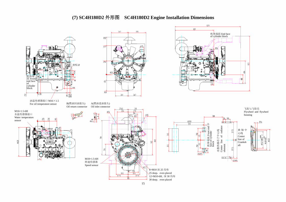
(7) SC4H180D2 外形图 SC4H180D2 Engine Installation Dimensions
机体端面 Front end face of cylinder block
油温传感器接口 M16×1.5
For oil temperature sensor
机体端面 End face of cylinder block
飞轮与飞轮壳
Flywheel and flywheel
housing
曲 轴 中
心线
Center
line of Cranksh
aft
水散热器芯子中心线
Cen
ter
lin
e o
f ra
dia
tor
elem
ent
机体端面
Fro
nt
end
fa
ce o
f cy
lin
der
b
lock
M16×1.5-6H
水温传感器接口
Water temperature
sensor
M18×1.5-6H
转速传感器
Speed sensor
8×M10 深 25 均布
25 deep,even placed
12×M10-6H, 深 30 均布
30 deep,even placed
B(燃油回油接头)
Oil return connector A(燃油进油接头)
Oil inlet connector

16
(8) SC7H250D2 外形图 SC7H250D2 Engine Installation Dimensions
机体端面 Front end face of cylinder block
油温传感器接口 M16×1.5
For oil temperature sensor
M16×1.5-6H
水温传感器接口
Water temperature
sensor
M18×1.5-6H
转速传感器
Speed sensor
水散热器芯子中心线
Cen
ter
lin
e o
f ra
dia
tor
elem
ent
机体端面
Fro
nt
end
fa
ce o
f cy
lin
der
b
lock
曲 轴 中
心线
Center
line of Cranksh
aft
飞轮与飞轮壳
Flywheel and flywheel
housing
机体端面 end face of cylinder block
8×M10 深 25 均布 25 deep,even placed
12×M10-6H, 深 30 均布 30 deep,even placed
B(燃油回油接头)
Oil return connector
A(燃油进油接头)
Oil inlet connector
17
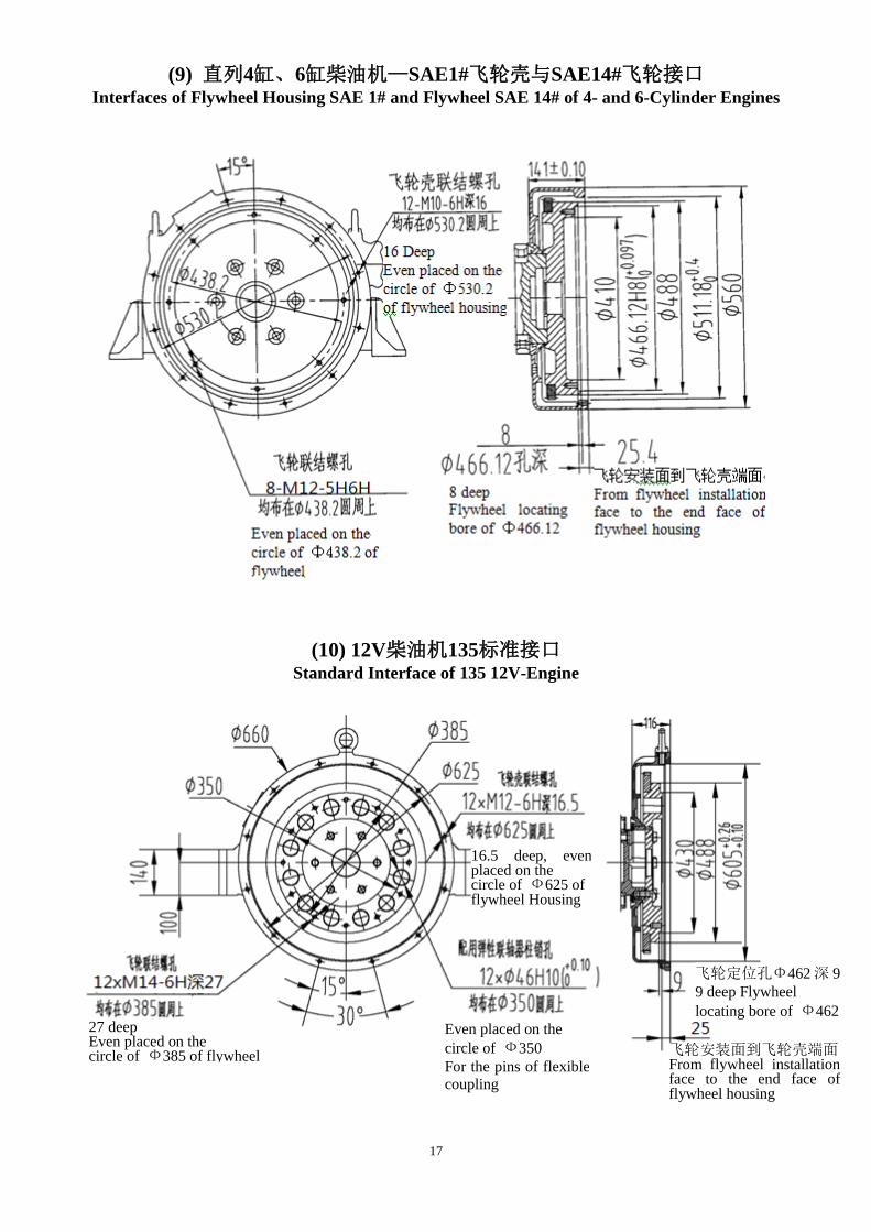
(9) 直列4缸、6缸柴油机—SAE1#飞轮壳与SAE14#飞轮接口
Interfaces of Flywheel Housing SAE 1# and Flywheel SAE 14# of 4- and 6-Cylinder Engines
(10) 12V柴油机135标准接口
Standard Interface of 135 12V-Engine
27 deep Even placed on the circle of Ф385 of flywheel
16.5 deep, even placed on the circle of Ф625 of flywheel Housing
Even placed on the
circle of Ф350
For the pins of flexible
coupling
飞轮安装面到飞轮壳端面 From flywheel installation face to the end face of flywheel housing
飞轮定位孔Φ462 深 9
9 deep Flywheel
locating bore of Ф462

18
(11) 12V 柴油机 SAE 接口(1)—SAE0#飞轮壳与 SAE18#飞轮接口
SAE Interface of 12V Engine (1)Flywheel Housing SAE 0 # and Flywheel SAE 18#
(12) 12V柴油机SAE接口(2)—SAE1/2#飞轮壳与SAE14#飞轮接口
SAE Interface of 12V Engine(2)Flywheel Housing SAE 1/2# and Flywheel SAE 14#
27 deep
16.5 deep

19
(13) G128系列柴油机—SAE1#飞轮壳与SAE14#飞轮接口
SAE Interface of G128 Series Engine —Flywheel Housing SAE 1# and Flywheel SAE 14#
(14) D114系列柴油机—SAE2#飞轮壳与SAE11 1/2#飞轮接口
SAE Interface of 114 Series Engine— Flywheel Housing SAE 2# and Flywheel SAE 11 1/2#
25 deep
25 deep
18 deep, even placed 24 deep, even placed

20
第三章 柴油机的安装与连接
1 柴油机的安装
1.1. 柴油机的安装方式可根据用户的安装需求,提供两点或四点支撑的方式。柴油机、发电
机、散热器共同安装在同一个公共底架上,一般采用弹性安装方式,其中柴油机安装所
用的减震器为用户可选件,采用合适的减震器能有效地降低柴油机、发电机工作时的振
动影响。
1.2. 发电机组安装的基础一定要坚实可靠,支撑面应水平平整,机组安装时一定要找平。机
组公共底架与基础之间应采取一定的减震措施,保证机组有好的隔振效果,以降低和减
轻机组工作时对周围其它设备和建筑物的影响。
1.3. 当机组在机房布置时,一定要注意柴油机及机组的操作、使用、维护管理和维修的空间
位置。
2 动力输出接口的连接
1 当柴油机与双轴承结构的发电机连接时,可采用柴油机飞轮壳与发电机止口法兰定位的
方式,如不采用止口定位的方式,则应在连接时校正柴油机与发电机轴线的同轴度,同
轴度误差应不大于Φ0.2mm。
2 柴油机的输出接口采用国际通用的标准SAE接口。柴油机与发电机连接时,发电机的法
兰接口与柴油机飞轮壳止口配合,发电机的弹性联轴器片与飞轮凹止口配合。弹性联轴
器片与飞轮的安装建议采用8.8级及以上螺栓,采用硬垫圈,不要采用弹簧垫圈。
3 冷却系统安装
1 散热器安装时,紧固牢靠。当安装在移动电站时,与车架的连接必须采用减振垫,采用
减振垫的目的是为了隔离和吸收来自车架的部份振动和冲击。
2 为使冷却效果达到最佳,建议散热器安装时,风扇前端面至散热器芯子的距离应至少大
于50 mm;护风罩与风扇叶尖的径向间隙均匀,且不应超过风扇直径的2.5 %,或者15 mm
~20 mm;风扇伸入护风罩的轴向位置,有1/3风扇投影宽度在护风圈内.。
3 机房使用时,应有足够的通风面积,应保证散热器热风的顺畅排出。
4 当柴油机在低于0℃环境条件使用时,应使用防冻冷却液。
4 电器仪表控制系统的安装与连接
1 柴油机电器仪表控制系统均为24V直流电源,电起动;发电机为整体式交流发电机;采
用负极搭铁单线制。
2 蓄电池由用户自配,建议蓄电池容量不小于150A.h。起动电缆线截面积应大于50mm²,

21
充电电源线截面积大于4mm²,其余连接线为2.5mm²。
3 柴油机出厂时一般不带仪表系统,仪表系统作为用户选用件由用户自行选购和安装。部
分带仪表的机型在出厂时,仪表箱线束已经连接好,无须用户接线。如需更换线束,只
需按线束上的号码一一对应的接入仪表箱和柴油机上对应的编号接口即可。
4 仪表应安装在振动较小的地方,避开排气系统直接传热或近距离热辐射,排气管靠近仪
表部位应用隔热材料包裹,以免温度过高引起仪表失灵。在安装过程中应避免对仪表箱
体的强烈冲击。
5 电器系统的接线必须正确,正负极绝不可接错,否则将会损坏电器设备,导致柴油机不
能运行的严重后果。
6 带电子调速器的控制系统的安装、使用和接线方法参照《电子调速器说明书》。
22
3 Engine Installation and Connection
3.1 Installation
1.Engine installation varies from the requirement of users. There are 2-point engine support and
4-point engine support to select. Engine, generator and radiator are mounted on a same base with
elastic mounting method. Vibration isolation for engine mounting is for option. Proper isolator
provides effective reduction of vibration arising from engine and generator operation.
2.The ground for a generating set should be solid, reliable and flat. Vibration isolation should be
employed between the ground and the base to reduce and lighten vibration effect on surrounding
equipment and buildings when the generating set operates. .
3.Enough space for operation, maintenance and repair of generating set should be maintained
when making its layout.
3.2 PTO connection
1. When connecting an engine to dual-bearing structured generator, use the flange of a generator
and the flange bore of a flywheel housing for setting, otherwise the coaxial of an engine and a
generator should be controlled within Φ0.2mm.
2. SEA connection is adopted for PTO. When connecting an engine to a generator, match the
generator flange to the stop face of the engine flywheel housing, and the flexible coupling plate of
the generator to the recess stop face of the flywheel. It is recommended to use the bolt of Grade
8.8, hard washer instead of spring washer for connection.
3.3 Cooling system installation
1. Radiator should be secured. Cushion should b used between the radiator and the chassis to
isolate and absorb part of vibration and impact from the chassis.
2. For an optimal cooling effect, it is recommended to keep at least 50 mm between the front end
face of a fan and a radiator element, even clearance of less than 2.5 % of the fan diameter or 15-20
mm between the fan shroud and the tips of the fan, and one-third projected width of the fan within
the fan shroud.
3. When the engine is chambered, enough space should be maintained to ensure a good discharge of
hot wind from the radiator.
4. Coolant with anti-freezing additive should be used when an engine is operated under 0℃.

23
3.4 Installation and connection of instrument and control system
1. All instrument and control system of the engine are supplied with 24V CD electric power and an
engine is started by an electric motor. An alternator is used with single negative grounding
system.
2. Battery is not provided with engine. It is suggested to use a battery with capacity not less than
150A•h. The section area of starting cable should be over 50 mm², electric charging cable over 4
mm² and rest wires over 2.5 mm².
3. Instrument is for option and not usually provided with an engine. Some engines equipped with
an instrument box are provided with connected harness and no more wire connection is required.
When changing harness, it only requires connecting the ends of harness to the corresponding
terminals of instrument box and engine according to their numbers.
4. Instrument should be installed in the place where is subject to less vibration, and away from
direct heat conduction or radiation of exhaust system. It is required to shield exhaust manifold
with heat isolation material if the instrument is nearby to avoid its malfunction due to high
temperature. It is also required to keep an instrument box from sever impact during installation.
5. It is required to make a correct wire connection of an electrical system. Never make any wrong
connection with positive to negative, which will damage electrical equipment and lead to failure in
engine operation.
6. For the installation, usage and wire connection of the control system for an electronic governor,
refer to Operation Manual for Electronic Governor.
18 deep,
even placed